WO2016063620A1 - Dispositif de changement de distance d'image virtuelle, procédé de changement de distance d'image virtuelle, programme - Google Patents
Dispositif de changement de distance d'image virtuelle, procédé de changement de distance d'image virtuelle, programme Download PDFInfo
- Publication number
- WO2016063620A1 WO2016063620A1 PCT/JP2015/074108 JP2015074108W WO2016063620A1 WO 2016063620 A1 WO2016063620 A1 WO 2016063620A1 JP 2015074108 W JP2015074108 W JP 2015074108W WO 2016063620 A1 WO2016063620 A1 WO 2016063620A1
- Authority
- WO
- WIPO (PCT)
- Prior art keywords
- virtual image
- distance
- image
- user
- information
- Prior art date
Links
Images


Classifications
-
- G—PHYSICS
- G02—OPTICS
- G02B—OPTICAL ELEMENTS, SYSTEMS OR APPARATUS
- G02B27/00—Optical systems or apparatus not provided for by any of the groups G02B1/00 - G02B26/00, G02B30/00
- G02B27/01—Head-up displays
- G02B27/017—Head mounted
- G02B27/0172—Head mounted characterised by optical features
-
- G—PHYSICS
- G02—OPTICS
- G02B—OPTICAL ELEMENTS, SYSTEMS OR APPARATUS
- G02B27/00—Optical systems or apparatus not provided for by any of the groups G02B1/00 - G02B26/00, G02B30/00
- G02B27/0093—Optical systems or apparatus not provided for by any of the groups G02B1/00 - G02B26/00, G02B30/00 with means for monitoring data relating to the user, e.g. head-tracking, eye-tracking
-
- G—PHYSICS
- G02—OPTICS
- G02B—OPTICAL ELEMENTS, SYSTEMS OR APPARATUS
- G02B27/00—Optical systems or apparatus not provided for by any of the groups G02B1/00 - G02B26/00, G02B30/00
- G02B27/01—Head-up displays
- G02B27/0179—Display position adjusting means not related to the information to be displayed
-
- G—PHYSICS
- G02—OPTICS
- G02B—OPTICAL ELEMENTS, SYSTEMS OR APPARATUS
- G02B27/00—Optical systems or apparatus not provided for by any of the groups G02B1/00 - G02B26/00, G02B30/00
- G02B27/02—Viewing or reading apparatus
-
- G—PHYSICS
- G06—COMPUTING; CALCULATING OR COUNTING
- G06F—ELECTRIC DIGITAL DATA PROCESSING
- G06F3/00—Input arrangements for transferring data to be processed into a form capable of being handled by the computer; Output arrangements for transferring data from processing unit to output unit, e.g. interface arrangements
- G06F3/01—Input arrangements or combined input and output arrangements for interaction between user and computer
- G06F3/011—Arrangements for interaction with the human body, e.g. for user immersion in virtual reality
- G06F3/013—Eye tracking input arrangements
-
- G—PHYSICS
- G06—COMPUTING; CALCULATING OR COUNTING
- G06F—ELECTRIC DIGITAL DATA PROCESSING
- G06F3/00—Input arrangements for transferring data to be processed into a form capable of being handled by the computer; Output arrangements for transferring data from processing unit to output unit, e.g. interface arrangements
- G06F3/14—Digital output to display device ; Cooperation and interconnection of the display device with other functional units
-
- G—PHYSICS
- G09—EDUCATION; CRYPTOGRAPHY; DISPLAY; ADVERTISING; SEALS
- G09G—ARRANGEMENTS OR CIRCUITS FOR CONTROL OF INDICATING DEVICES USING STATIC MEANS TO PRESENT VARIABLE INFORMATION
- G09G5/00—Control arrangements or circuits for visual indicators common to cathode-ray tube indicators and other visual indicators
-
- H—ELECTRICITY
- H04—ELECTRIC COMMUNICATION TECHNIQUE
- H04N—PICTORIAL COMMUNICATION, e.g. TELEVISION
- H04N5/00—Details of television systems
- H04N5/64—Constructional details of receivers, e.g. cabinets or dust covers
-
- G—PHYSICS
- G02—OPTICS
- G02B—OPTICAL ELEMENTS, SYSTEMS OR APPARATUS
- G02B27/00—Optical systems or apparatus not provided for by any of the groups G02B1/00 - G02B26/00, G02B30/00
- G02B27/01—Head-up displays
- G02B27/0101—Head-up displays characterised by optical features
- G02B2027/0138—Head-up displays characterised by optical features comprising image capture systems, e.g. camera
-
- G—PHYSICS
- G02—OPTICS
- G02B—OPTICAL ELEMENTS, SYSTEMS OR APPARATUS
- G02B27/00—Optical systems or apparatus not provided for by any of the groups G02B1/00 - G02B26/00, G02B30/00
- G02B27/01—Head-up displays
- G02B27/0149—Head-up displays characterised by mechanical features
- G02B2027/0154—Head-up displays characterised by mechanical features with movable elements
-
- G—PHYSICS
- G02—OPTICS
- G02B—OPTICAL ELEMENTS, SYSTEMS OR APPARATUS
- G02B27/00—Optical systems or apparatus not provided for by any of the groups G02B1/00 - G02B26/00, G02B30/00
- G02B27/01—Head-up displays
- G02B27/0179—Display position adjusting means not related to the information to be displayed
- G02B2027/0185—Displaying image at variable distance
-
- H—ELECTRICITY
- H04—ELECTRIC COMMUNICATION TECHNIQUE
- H04N—PICTORIAL COMMUNICATION, e.g. TELEVISION
- H04N13/00—Stereoscopic video systems; Multi-view video systems; Details thereof
- H04N13/30—Image reproducers
- H04N13/332—Displays for viewing with the aid of special glasses or head-mounted displays [HMD]
- H04N13/344—Displays for viewing with the aid of special glasses or head-mounted displays [HMD] with head-mounted left-right displays
-
- H—ELECTRICITY
- H04—ELECTRIC COMMUNICATION TECHNIQUE
- H04N—PICTORIAL COMMUNICATION, e.g. TELEVISION
- H04N13/00—Stereoscopic video systems; Multi-view video systems; Details thereof
- H04N13/30—Image reproducers
- H04N13/366—Image reproducers using viewer tracking
- H04N13/383—Image reproducers using viewer tracking for tracking with gaze detection, i.e. detecting the lines of sight of the viewer's eyes
-
- H—ELECTRICITY
- H04—ELECTRIC COMMUNICATION TECHNIQUE
- H04N—PICTORIAL COMMUNICATION, e.g. TELEVISION
- H04N2213/00—Details of stereoscopic systems
- H04N2213/008—Aspects relating to glasses for viewing stereoscopic images
Definitions
- This relates to a virtual image distance changing device, a virtual image distance changing method, and a program.
- a head-mounted display (hereinafter referred to as “HMD”) that is used by being mounted on a user's head is known as an image display device that displays an image.
- HMD head-mounted display
- Japanese Patent Laid-Open No. 2012-194501 discloses a so-called see-through type head-mounted display that can visually recognize the outside world while visually recognizing a virtual image presented at a predetermined distance. In this case, if it is determined that the user is walking so as not to interfere with walking even if the user is used during walking, the distance of the virtual image to be presented (virtual image distance) is infinite by moving the lens.
- a technique for making the distance closer than the distance is disclosed.
- the virtual image distance is fixed or set regardless of the displayed object. Therefore, in the prior art, a virtual image corresponding to the actual depth of the object, the distance between the camera and the object when the object to be viewed is taken, or the distance between the object assumed in computer graphics, etc. The object is not displayed at the distance.
- an object of the present invention is to realize a virtual image distance changing device or the like that can present a visual target that is a visual target of a user at a virtual image distance corresponding to the actual depth or the like of the target.
- the virtual image distance changing device of the present invention includes a display panel that displays an image according to image information, guides the image displayed on the display panel to the user's eyes, and displays the virtual image according to the image.
- An optical system to be visually recognized by the user depth information acquisition means for acquiring depth information which is displayed on the display panel and represents the depth of the visual recognition object which is the visual recognition target of the user, and the virtual image according to the depth information includes a distance changing unit that changes a virtual image distance representing a distance visually recognized by the user.
- the depth information acquisition unit includes a gaze direction acquisition unit that acquires gaze direction information indicating a gaze direction of the user, and the acquired gaze direction.
- Depth estimation means for estimating the depth based on information.
- the virtual image distance changing device according to any one of (1) to (6), wherein the distance changing unit is configured to perform a predetermined change after the scene change when the scene represented by the image information is changed.
- the virtual image distance is changed after the period has elapsed.
- the virtual image distance changing device according to any one of (1) to (7), wherein the distance changing unit moves the lens included in the display panel or the optical system, thereby moving the virtual image. It is characterized by changing the distance.
- the virtual image distance changing device is a head mounted display.
- the virtual image distance changing method of the present invention displays an image corresponding to image information, guides the image displayed on the display panel to the user's eyes, and visually recognizes the virtual image corresponding to the image to the user. And acquiring depth information representing the depth of the visual target object that is displayed on the display panel, and representing the distance at which the virtual image is viewed by the user according to the depth information. The distance is changed.
- the program according to the present invention displays a display panel that displays an image according to image information, guides the image displayed on the display panel to the user's eyes, and visually recognizes the virtual image corresponding to the image to the user.
- a depth information acquisition means for acquiring depth information that is displayed on the display panel and represents a depth of a visual target that is a visual target of the user,
- the computer is caused to function as distance changing means for changing a virtual image distance representing a distance at which the virtual image is visually recognized by the user according to the depth information.
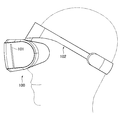
- FIG. 1 is a diagram showing an example of an outline of the HMD in the present embodiment. Specifically, FIG. 1 shows an example of an outline of a side view of the HMD 100 when the HMD 100 is worn on the user's head.
- the HMD 100 includes a display panel 101 that displays a three-dimensional image in accordance with the acquired image information.
- the display panel 101 displays a right-eye image in the right region and a left-eye image in the left region.
- the display panel 101 is not limited to the above, and may be configured to display a three-dimensional image by another method such as a frame sequential method.
- the display panel 101 is constituted by, for example, a liquid crystal display panel 101, an organic EL display panel 101, or the like.
- the HMD 100 guides an image displayed on the display panel 101 to the user's eyes and makes the user visually recognize a virtual image corresponding to the image, and a lens or a display panel included in the optical system.
- a distance changing unit that changes a virtual image distance representing a distance at which the virtual image is visually recognized by the user by moving 101, will be described later in detail.
- the HMD 100 includes, for example, a mounting band 102 for mounting the HMD 100 on the user's head.
- the configuration of the HMD 100 is an example, and the present embodiment is not limited to the above.
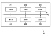
- FIG. 2 is a diagram for explaining an example of the hardware configuration of the HMD.
- the HMD 100 includes, for example, a control unit 201, a storage unit 202, a communication unit 203, an operation unit 204, a display unit 205, and a drive unit 206.
- the control unit 201, the storage unit 202, the communication unit 203, the operation unit 204, the display unit 205, and the drive unit 206 are connected to each other via an internal bus 207.
- the control unit 201 is, for example, a CPU or MPU, and operates according to a program stored in the storage unit 202.
- the storage unit 202 is an information recording medium configured by an information recording medium such as a ROM or a RAM, and holds a program executed by the control unit 201.
- the storage unit 202 also operates as a work memory for the control unit 201.
- the program may be provided by being downloaded via a network, for example, or may be provided by various computer-readable information recording media such as a CD-ROM, a DVD-ROM, and a semiconductor memory. May be.
- the communication unit 203 connects the HMD 100 to another information processing apparatus (for example, a game machine or a server) (not shown) via a network.
- the operation unit 204 includes, for example, a button, a controller, and the like, and outputs the content of the instruction operation to the control unit 201 in accordance with a user instruction operation.
- a display unit 205 corresponds to the display panel 101 and displays information in accordance with an instruction from the control unit 201.
- the drive unit 206 includes, for example, a motor (not shown) and a driver (not shown) that supplies a drive current to the motor.
- the driver supplies a drive current to the motor in accordance with an instruction from the control unit 201, whereby the motor is rotated.
- the display unit 205 is connected to a motor via a gear unit (not shown) or the like, and is supported so that the display unit 205 is moved by the rotation of the motor. In other words, the display unit 205 is moved by the rotation of the motor, and a virtual image distance to be described later is changed.
- the present embodiment is based on the virtual image distance, such as moving a lens constituting the optical system. As long as it can be changed, it is not limited to the said structure.
- the configuration of the HMD 100 shown in FIG. 2 is an example, and the present invention is not limited to this.
- the HMD 100 may include a camera, for example, and may be configured to acquire line-of-sight direction information representing a user's line-of-sight direction, which will be described later, in accordance with imaging information from the camera.
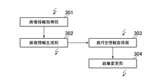
- FIG. 3 is a diagram illustrating a main example of a functional configuration of the control unit of the HMD.
- the HMD 100 functionally includes, for example, an image information acquisition unit 301, an image information generation unit 302, a depth information acquisition unit 303, and a distance change unit 304.
- the image information acquisition unit 301 acquires image information.
- the image information acquisition unit 301 may be configured to acquire image information from an external information processing apparatus (for example, a game machine or server) (not shown), or the storage unit 202.
- the image information stored in the memory may be acquired.
- the image information generation unit 302 generates a frame image to be displayed on the display panel 101 for each frame, for example, based on the image information acquired by the image information acquisition unit 301.
- the frame image is a frame image for displaying a three-dimensional image on the display panel 101.
- the frame image is displayed in a frame image for the right eye and a frame image for the left eye or a frame sequential method as described above. Corresponds to the frame image.
- the display panel 101 displays the generated frame image.
- the depth information acquisition unit 303 acquires depth information corresponding to the frame image.
- the depth information corresponds to, for example, the depth of the object visually recognized by the user, for example, the distance from the center point between the user's eyes to the visually recognized object that is a virtual image.
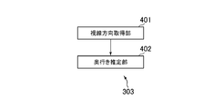
- the depth information acquisition unit 303 includes a line-of-sight direction acquisition unit 401 and a depth estimation unit 402 as illustrated in FIG.
- the line-of-sight direction acquisition unit 401 acquires line-of-sight direction information representing the line-of-sight directions of both eyes of the user, for example.
- the line-of-sight direction information corresponds to each angle from the position of each eye of the user to the visual recognition target.
- the depth estimation unit 402 estimates the depth of the object visually recognized by the user (for example, corresponding to the distance from the center point between the eyes of the user to the visual object that is a virtual image) based on the line-of-sight direction, Obtained as depth information. More specifically, for example, the depth estimation unit 402 calculates the depth from the distance between both eyes of the user and the angle of each line of sight.
- the distance between the eyes of the user corresponds to, for example, the distance between the centers of the openings where the user hits each eye in the HMD 100.
- the acquisition of the depth information is an example, and the present embodiment is not limited to this.
- an object viewed from the line-of-sight direction may be specified, and the depth may be estimated from the parallax.
- the acquisition of the gaze direction information is well known as, for example, EyeETracking (Gaze ⁇ ⁇ Tracking) for detecting the gaze direction in real time, and the description of further details is omitted.
- the depth estimation unit 402 acquires, for example, a preset so-called Depth map that represents depth information of each object included in the image information together with the image information, and based on the Depth map and the line-of-sight direction information. You may comprise so that depth information may be acquired.
- the line-of-sight direction acquisition unit 401 may be omitted, and the depth information based on a predetermined representative point such as the center of the displayed image may be acquired using a depth map.
- the depth map may be configured to include only depth information of the representative point.
- the depth map is generated and set in advance when image information is generated.
- the image information acquisition unit 301 is configured to acquire the image information together with the image information.
- the distance changing unit 304 changes the virtual image distance of the virtual image visually recognized by the user by instructing the driving unit 206 based on the depth information. That is, the distance changing unit changes the virtual image distance based on, for example, the depth of the visually recognized object one frame before.
- the present embodiment is not limited to the depth of the visually recognized object one frame before, and the virtual image distance is changed based on the depth several frames before and the statistical value (for example, the average value) of the depth in several frames. You may comprise.
- the optical system is formed by one lens for each eye, and the distance changing unit 304 moves the display panel 101 to move the lens and the display panel 101. An example of changing the distance between them will be described below.
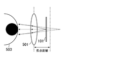
- FIG. 5A and FIG. 5B are diagrams for explaining the change of the virtual image distance in the present embodiment.
- the distance changing unit 304 moves the display panel 101 away from the lens 501 as shown in FIG. 5B, for example, when the acquired depth information is large (that is, when presenting a virtual image viewed in the distance).
- the display panel 101 is moved closer to the lens 501 as shown in FIG. 5A.
- a well-known motor, a gear, etc. are used for the said movement, description is abbreviate
- a lens 501 is provided for each user's eye 503, and the user displays an image displayed on the display panel 101 via the lens 501. And a virtual image distance based on the distance between the display panel 501 and the display panel 501. Note that an arrow 502 in FIG. 5A indicates the moving direction of the display panel 101.
- the distance changing unit 304 may be configured to be able to move the display panel 101 within a range of 2.5 mm.
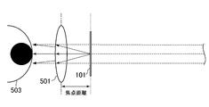
- FIGS. 7A and 7B show a predetermined short distance to infinity as shown in FIGS. 7A and 7B.
- FIG. 7A shows a case of a short distance
- FIG. 7B shows a schematic diagram of a case of infinity.
- the optical system is mainly composed of one lens 501 for each eye.
- the optical system may be composed of a plurality of lenses. The operation in this case is different from that in the case where the optical system is configured by the lens 1 described above, but it goes without saying that the virtual image distance is changed according to the depth information.
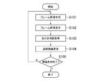
- FIG. 8 is a diagram showing an example of an outline of the processing flow of the HMD 100 in the present embodiment.
- the image information generation unit 302 generates a frame image to be displayed on the display panel 101, for example, every frame based on the image information acquired by the image information acquisition unit 301 (S101).
- the display panel 101 displays the generated frame image (S102).
- the depth information acquisition unit 303 acquires depth information corresponding to the frame image (S103).
- the depth information may be configured to be estimated based on the line-of-sight direction, for example, or may be configured to be acquired based on the Depth map.
- the distance changing unit 304 changes the virtual image distance based on the depth information (S104).
- the image information generation unit 302 determines whether or not the display of all image information has been completed (S105). Specifically, for example, the image information generation unit 302 determines that the display of all image information has been completed when the display of the image information has been completed by the user or the generation of the last frame image has been completed. to decide.
- the process returns to S101, and the frame image to be displayed on the display panel 101 is displayed next. Is repeated. On the other hand, when the image information generation unit 302 determines that the display of all the image information has been completed, the process ends.
- the flow of the above process is an example, and the present embodiment is not limited to the above.
- the case where the display panel 101 is moved based mainly on the depth information corresponding to each frame image has been described.
- every predetermined number of frame images for example, every predetermined number of frame images).
- the depth information may be acquired and the display panel 101 may be moved as described above.
- the above-described depth map is used for estimation of depth information, for example, the depth information may be acquired before S102.
- the actual depth of the object for example, the actual depth of the object, the distance between the camera and the object when the visually recognized object is photographed, or the distance between the object assumed in computer graphics, etc. It is possible to realize a head mounted display or the like that can visually recognize a visually recognized object at a corresponding virtual image distance. Thereby, for example, the user can visually recognize the visually recognized object more naturally, and the visually recognized visually recognized object can be visually recognized.
- the present invention is not limited to the above-described embodiment, and is substantially the same configuration as the configuration shown in the above-described embodiment, a configuration that exhibits the same operational effects, or a configuration that can achieve the same purpose. May be replaced.
- a predetermined setting mode is provided to limit the range of the virtual image distance.
- You may comprise. More specifically, the first setting mode may be limited to a range from 1 m to 10 m, and the second setting mode may be limited to a range from 10 m to infinity.
- the virtual image can be visually recognized within a range according to each user's request. More specifically, for example, when the user is nearsighted, the first setting mode is used, and when the user is farsighted, the second setting mode is used, so that the user can comfortably view. It is possible to visually recognize an object at a virtual image distance.
- a mode may be provided in which the depth information is changed to a virtual image distance obtained by multiplying the depth information by a predetermined value in accordance with the depth information. For example, when the depth information is 1 m, the virtual image distance is 10 m, and when the depth information is 10 m, the virtual image distance is 100 m. Further, for example, when the depth information is equal to or greater than a predetermined value, the distance may be changed to a farther virtual image distance, and when the depth information is equal to or smaller than the predetermined value, the distance may be changed to a closer virtual image distance. . Thereby, depending on the image information, more powerful visual recognition may be realized.
- the virtual image distance is changed according to the line-of-sight direction within the predetermined period without changing the virtual image distance for a predetermined period after the scene change. It may be configured. Thereby, for example, even in a scene where the virtual image distance suddenly moves from infinity to a short distance, the user can visually recognize the visual recognition object more comfortably.
- the distance changing unit 304 may be configured to change the virtual image distance after the line of sight moves, and not to change the virtual image distance while the line of sight moves. Specifically, for example, the virtual image distance is not changed while the visual line direction acquisition unit 401 detects the movement of the visual line direction, and the virtual image distance is changed after the movement of the visual line is stopped. Specifically, for example, the virtual image distance is changed when there is no movement of the line of sight for a predetermined period. Further, when the line of sight moves beyond a predetermined distance, the virtual image distance may not be changed. Thereby, depending on a scene, a user can visually recognize a visual recognition object more comfortably.
- the processing is performed by an information processing apparatus (game device or server) connected to the HMD 100. Etc.).
- the HMD 100 may acquire parallax direction information, transmit the parallax direction to the information processing apparatus or the like, and the HMD 100 may acquire depth information generated in the information processing apparatus. .
- the HMD 100 is described as an example of the virtual image distance changing device.
- the virtual image distance changing device is a light source (diffusion) through an optical system such as an electronic finder, a digitized microscope eyepiece, and electronic binoculars. Includes devices that see reflected light.
- each said modification may be used as long as it does not contradict each other, for example, it is comprised so that a virtual image distance may not be changed while a user's eyes
Abstract
Priority Applications (4)
| Application Number | Priority Date | Filing Date | Title |
|---|---|---|---|
| CN201580056030.7A CN107077002A (zh) | 2014-10-23 | 2015-08-26 | 虚拟图像距离改变装置、虚拟图像距离改变方法以及程序 |
| EP15852667.3A EP3211471A4 (fr) | 2014-10-23 | 2015-08-26 | Dispositif de changement de distance d'image virtuelle, procédé de changement de distance d'image virtuelle, programme |
| US15/502,903 US20170255021A1 (en) | 2014-10-23 | 2015-08-26 | Virtual image distance changing device, virtual image distance changing method, and program |
| JP2016555122A JP6307170B2 (ja) | 2014-10-23 | 2015-08-26 | 虚像距離変更装置、虚像距離変更方法、プログラム |
Applications Claiming Priority (2)
| Application Number | Priority Date | Filing Date | Title |
|---|---|---|---|
| JP2014-216656 | 2014-10-23 | ||
| JP2014216656 | 2014-10-23 |
Publications (1)
| Publication Number | Publication Date |
|---|---|
| WO2016063620A1 true WO2016063620A1 (fr) | 2016-04-28 |
Family
ID=55760668
Family Applications (1)
| Application Number | Title | Priority Date | Filing Date |
|---|---|---|---|
| PCT/JP2015/074108 WO2016063620A1 (fr) | 2014-10-23 | 2015-08-26 | Dispositif de changement de distance d'image virtuelle, procédé de changement de distance d'image virtuelle, programme |
Country Status (5)
| Country | Link |
|---|---|
| US (1) | US20170255021A1 (fr) |
| EP (1) | EP3211471A4 (fr) |
| JP (1) | JP6307170B2 (fr) |
| CN (1) | CN107077002A (fr) |
| WO (1) | WO2016063620A1 (fr) |
Cited By (2)
| Publication number | Priority date | Publication date | Assignee | Title |
|---|---|---|---|---|
| JP2018045217A (ja) * | 2016-09-14 | 2018-03-22 | 伊藤 克之 | 遠景画像装置 |
| WO2021024827A1 (fr) * | 2019-08-08 | 2021-02-11 | ソニー株式会社 | Système d'affichage d'image chirurgicale, dispositif de traitement d'image, et procédé de traitement d'image |
Families Citing this family (12)
| Publication number | Priority date | Publication date | Assignee | Title |
|---|---|---|---|---|
| CN108066981A (zh) * | 2016-11-12 | 2018-05-25 | 金德奎 | 一种基于位置和图像识别的ar或mr游戏方法及系统 |
| EP4276522A3 (fr) | 2018-05-29 | 2024-01-31 | Apple Inc. | Système optique pour visiocasque |
| CN111479104A (zh) * | 2018-12-21 | 2020-07-31 | 托比股份公司 | 用于计算视线会聚距离的方法 |
| CN109683336A (zh) * | 2019-01-14 | 2019-04-26 | 杨铭轲 | 显示装置及其显示方法 |
| CN110188643A (zh) * | 2019-05-21 | 2019-08-30 | 北京市商汤科技开发有限公司 | 一种信息显示方法及装置、存储介质 |
| CN110308560B (zh) * | 2019-07-03 | 2022-09-30 | 南京玛克威信息科技有限公司 | Vr设备的控制方法 |
| CN112241068A (zh) * | 2019-07-18 | 2021-01-19 | 三星电子株式会社 | 能够多深度表达的图像显示装置 |
| WO2021010772A1 (fr) * | 2019-07-18 | 2021-01-21 | 삼성전자(주) | Dispositif d'affichage d'image permettant d'exprimer de multiples profondeurs |
| CN110840721B (zh) * | 2019-11-25 | 2022-04-15 | 北京耐德佳显示技术有限公司 | 一种基于近眼显示的视力防控、训练方法及近眼显示设备 |
| KR20210091580A (ko) | 2020-01-14 | 2021-07-22 | 삼성전자주식회사 | 3차원 영상 표시 장치 및 방법 |
| CN113433628A (zh) * | 2021-06-23 | 2021-09-24 | 河南鑫宇光科技股份有限公司 | 一种低串扰的单波长光器件 |
| CN114326295B (zh) * | 2022-03-15 | 2022-07-19 | 之江实验室 | 一种氧化锌微纳图案的飞秒激光直写方法 |
Citations (3)
| Publication number | Priority date | Publication date | Assignee | Title |
|---|---|---|---|---|
| JP2007267261A (ja) * | 2006-03-29 | 2007-10-11 | Toshiba Corp | 立体表示装置 |
| JP2010139901A (ja) * | 2008-12-15 | 2010-06-24 | Brother Ind Ltd | ヘッドマウントディスプレイ |
| JP2013186641A (ja) * | 2012-03-07 | 2013-09-19 | Seiko Epson Corp | 頭部装着型表示装置および頭部装着型表示装置の制御方法 |
Family Cites Families (8)
| Publication number | Priority date | Publication date | Assignee | Title |
|---|---|---|---|---|
| JP3787939B2 (ja) * | 1997-02-27 | 2006-06-21 | コニカミノルタホールディングス株式会社 | 立体映像表示装置 |
| US20040212550A1 (en) * | 1999-12-16 | 2004-10-28 | Zhan He | Three-dimensional volumetric display |
| EP1784988A1 (fr) * | 2004-08-06 | 2007-05-16 | University of Washington | Afficheurs a balayage lumineux a fixation de distance de visionnage variable |
| US9304319B2 (en) * | 2010-11-18 | 2016-04-05 | Microsoft Technology Licensing, Llc | Automatic focus improvement for augmented reality displays |
| US20130083003A1 (en) * | 2011-09-30 | 2013-04-04 | Kathryn Stone Perez | Personal audio/visual system |
| US9880325B2 (en) * | 2013-08-14 | 2018-01-30 | Nvidia Corporation | Hybrid optics for near-eye displays |
| KR102077105B1 (ko) * | 2013-09-03 | 2020-02-13 | 한국전자통신연구원 | 사용자 인터랙션을 위한 디스플레이를 설계하는 장치 및 방법 |
| JP5420793B1 (ja) * | 2013-09-10 | 2014-02-19 | テレパシー インク | 画像の視認距離を調整できるヘッドマウントディスプレイ |
-
2015
- 2015-08-26 CN CN201580056030.7A patent/CN107077002A/zh active Pending
- 2015-08-26 US US15/502,903 patent/US20170255021A1/en not_active Abandoned
- 2015-08-26 JP JP2016555122A patent/JP6307170B2/ja active Active
- 2015-08-26 EP EP15852667.3A patent/EP3211471A4/fr active Pending
- 2015-08-26 WO PCT/JP2015/074108 patent/WO2016063620A1/fr active Application Filing
Patent Citations (3)
| Publication number | Priority date | Publication date | Assignee | Title |
|---|---|---|---|---|
| JP2007267261A (ja) * | 2006-03-29 | 2007-10-11 | Toshiba Corp | 立体表示装置 |
| JP2010139901A (ja) * | 2008-12-15 | 2010-06-24 | Brother Ind Ltd | ヘッドマウントディスプレイ |
| JP2013186641A (ja) * | 2012-03-07 | 2013-09-19 | Seiko Epson Corp | 頭部装着型表示装置および頭部装着型表示装置の制御方法 |
Non-Patent Citations (1)
| Title |
|---|
| See also references of EP3211471A4 * |
Cited By (2)
| Publication number | Priority date | Publication date | Assignee | Title |
|---|---|---|---|---|
| JP2018045217A (ja) * | 2016-09-14 | 2018-03-22 | 伊藤 克之 | 遠景画像装置 |
| WO2021024827A1 (fr) * | 2019-08-08 | 2021-02-11 | ソニー株式会社 | Système d'affichage d'image chirurgicale, dispositif de traitement d'image, et procédé de traitement d'image |
Also Published As
| Publication number | Publication date |
|---|---|
| EP3211471A4 (fr) | 2018-06-20 |
| CN107077002A (zh) | 2017-08-18 |
| US20170255021A1 (en) | 2017-09-07 |
| JPWO2016063620A1 (ja) | 2017-05-25 |
| EP3211471A1 (fr) | 2017-08-30 |
| JP6307170B2 (ja) | 2018-04-04 |
Similar Documents
| Publication | Publication Date | Title |
|---|---|---|
| JP6307170B2 (ja) | 虚像距離変更装置、虚像距離変更方法、プログラム | |
| JP6983258B2 (ja) | アイトラッキングを介した拡張された有効なアイボックスを有するニアアイディスプレイ | |
| US10726765B2 (en) | Using tracking of display device to control image display | |
| EP3526967B1 (fr) | Affichages informatiques non plans | |
| US20190018236A1 (en) | Varifocal aberration compensation for near-eye displays | |
| US10353207B2 (en) | Head-mounted display device and video display system | |
| EP3301545B1 (fr) | Programme informatique, procédé de suivi d'objets et dispositif d'affichage | |
| JP5420793B1 (ja) | 画像の視認距離を調整できるヘッドマウントディスプレイ | |
| WO2016038997A1 (fr) | Dispositif d'affichage, procédé d'attaque de dispositif d'affichage et dispositif électronique | |
| JP2014219621A (ja) | 表示装置、表示制御プログラム | |
| US20210201580A1 (en) | Artificial reality system with varifocal display of artificial reality content | |
| US11301969B1 (en) | Context aware dynamic distortion correction | |
| US10291896B2 (en) | Display control methods and apparatuses and display devices | |
| US20210037232A1 (en) | Driving method for calculating interpupillary distance and related head-mounted device | |
| JP2016210259A (ja) | ヘッドアップディスプレイ | |
| JP2015060071A (ja) | 画像表示装置、画像表示方法、および画像表示プログラム | |
| JP2015026286A (ja) | 表示装置、表示システムおよび表示装置の制御方法 | |
| CN111722401A (zh) | 显示装置、显示控制方法以及显示系统 | |
| JP2019008205A (ja) | ヘッドマウントディスプレイ装置 | |
| JP2019151205A (ja) | 車載表示装置、車載表示装置を制御する方法及びコンピュータプログラム | |
| US20230254466A1 (en) | Control device | |
| JP2019008204A (ja) | ヘッドマウントディスプレイ装置 | |
| JP2023143437A (ja) | 制御装置、制御方法、及び制御プログラム | |
| JP2016081463A (ja) | 表示制御装置、表示制御方法、表示制御プログラム、および投影装置 | |
| CN115668035A (zh) | 用于可穿戴设备的单视显示器 |
Legal Events
| Date | Code | Title | Description |
|---|---|---|---|
| 121 | Ep: the epo has been informed by wipo that ep was designated in this application |
Ref document number: 15852667 Country of ref document: EP Kind code of ref document: A1 |
|
| ENP | Entry into the national phase |
Ref document number: 2016555122 Country of ref document: JP Kind code of ref document: A |
|
| REEP | Request for entry into the european phase |
Ref document number: 2015852667 Country of ref document: EP |
|
| WWE | Wipo information: entry into national phase |
Ref document number: 2015852667 Country of ref document: EP |
|
| NENP | Non-entry into the national phase |
Ref country code: DE |
|
| WWE | Wipo information: entry into national phase |
Ref document number: 15502903 Country of ref document: US |