WO2016063620A1 - Virtual-image-distance changing device, method for changing virtual image distance, program - Google Patents

Virtual-image-distance changing device, method for changing virtual image distance, program Download PDF

Info

Publication number
WO2016063620A1
WO2016063620A1 PCT/JP2015/074108 JP2015074108W WO2016063620A1 WO 2016063620 A1 WO2016063620 A1 WO 2016063620A1 JP 2015074108 W JP2015074108 W JP 2015074108W WO 2016063620 A1 WO2016063620 A1 WO 2016063620A1
Authority
WO
WIPO (PCT)
Prior art keywords
virtual image
distance
image
user
information
Prior art date
Application number
PCT/JP2015/074108
Other languages
French (fr)
Japanese (ja)
Inventor
友博 大戸
Original Assignee
株式会社ソニー・コンピュータエンタテインメント
Priority date (The priority date is an assumption and is not a legal conclusion. Google has not performed a legal analysis and makes no representation as to the accuracy of the date listed.)
Filing date
Publication date
Application filed by 株式会社ソニー・コンピュータエンタテインメント filed Critical 株式会社ソニー・コンピュータエンタテインメント
Priority to JP2016555122A priority Critical patent/JP6307170B2/en
Priority to CN201580056030.7A priority patent/CN107077002A/en
Priority to US15/502,903 priority patent/US20170255021A1/en
Priority to EP15852667.3A priority patent/EP3211471A4/en
Publication of WO2016063620A1 publication Critical patent/WO2016063620A1/en

Links

Images

Classifications

    • GPHYSICS
    • G02OPTICS
    • G02BOPTICAL ELEMENTS, SYSTEMS OR APPARATUS
    • G02B27/00Optical systems or apparatus not provided for by any of the groups G02B1/00 - G02B26/00, G02B30/00
    • G02B27/01Head-up displays
    • G02B27/017Head mounted
    • G02B27/0172Head mounted characterised by optical features
    • GPHYSICS
    • G02OPTICS
    • G02BOPTICAL ELEMENTS, SYSTEMS OR APPARATUS
    • G02B27/00Optical systems or apparatus not provided for by any of the groups G02B1/00 - G02B26/00, G02B30/00
    • G02B27/0093Optical systems or apparatus not provided for by any of the groups G02B1/00 - G02B26/00, G02B30/00 with means for monitoring data relating to the user, e.g. head-tracking, eye-tracking
    • GPHYSICS
    • G02OPTICS
    • G02BOPTICAL ELEMENTS, SYSTEMS OR APPARATUS
    • G02B27/00Optical systems or apparatus not provided for by any of the groups G02B1/00 - G02B26/00, G02B30/00
    • G02B27/01Head-up displays
    • G02B27/0179Display position adjusting means not related to the information to be displayed
    • GPHYSICS
    • G02OPTICS
    • G02BOPTICAL ELEMENTS, SYSTEMS OR APPARATUS
    • G02B27/00Optical systems or apparatus not provided for by any of the groups G02B1/00 - G02B26/00, G02B30/00
    • G02B27/02Viewing or reading apparatus
    • GPHYSICS
    • G06COMPUTING; CALCULATING OR COUNTING
    • G06FELECTRIC DIGITAL DATA PROCESSING
    • G06F3/00Input arrangements for transferring data to be processed into a form capable of being handled by the computer; Output arrangements for transferring data from processing unit to output unit, e.g. interface arrangements
    • G06F3/01Input arrangements or combined input and output arrangements for interaction between user and computer
    • G06F3/011Arrangements for interaction with the human body, e.g. for user immersion in virtual reality
    • G06F3/013Eye tracking input arrangements
    • GPHYSICS
    • G06COMPUTING; CALCULATING OR COUNTING
    • G06FELECTRIC DIGITAL DATA PROCESSING
    • G06F3/00Input arrangements for transferring data to be processed into a form capable of being handled by the computer; Output arrangements for transferring data from processing unit to output unit, e.g. interface arrangements
    • G06F3/14Digital output to display device ; Cooperation and interconnection of the display device with other functional units
    • GPHYSICS
    • G09EDUCATION; CRYPTOGRAPHY; DISPLAY; ADVERTISING; SEALS
    • G09GARRANGEMENTS OR CIRCUITS FOR CONTROL OF INDICATING DEVICES USING STATIC MEANS TO PRESENT VARIABLE INFORMATION
    • G09G5/00Control arrangements or circuits for visual indicators common to cathode-ray tube indicators and other visual indicators
    • HELECTRICITY
    • H04ELECTRIC COMMUNICATION TECHNIQUE
    • H04NPICTORIAL COMMUNICATION, e.g. TELEVISION
    • H04N5/00Details of television systems
    • H04N5/64Constructional details of receivers, e.g. cabinets or dust covers
    • GPHYSICS
    • G02OPTICS
    • G02BOPTICAL ELEMENTS, SYSTEMS OR APPARATUS
    • G02B27/00Optical systems or apparatus not provided for by any of the groups G02B1/00 - G02B26/00, G02B30/00
    • G02B27/01Head-up displays
    • G02B27/0101Head-up displays characterised by optical features
    • G02B2027/0138Head-up displays characterised by optical features comprising image capture systems, e.g. camera
    • GPHYSICS
    • G02OPTICS
    • G02BOPTICAL ELEMENTS, SYSTEMS OR APPARATUS
    • G02B27/00Optical systems or apparatus not provided for by any of the groups G02B1/00 - G02B26/00, G02B30/00
    • G02B27/01Head-up displays
    • G02B27/0149Head-up displays characterised by mechanical features
    • G02B2027/0154Head-up displays characterised by mechanical features with movable elements
    • GPHYSICS
    • G02OPTICS
    • G02BOPTICAL ELEMENTS, SYSTEMS OR APPARATUS
    • G02B27/00Optical systems or apparatus not provided for by any of the groups G02B1/00 - G02B26/00, G02B30/00
    • G02B27/01Head-up displays
    • G02B27/0179Display position adjusting means not related to the information to be displayed
    • G02B2027/0185Displaying image at variable distance
    • HELECTRICITY
    • H04ELECTRIC COMMUNICATION TECHNIQUE
    • H04NPICTORIAL COMMUNICATION, e.g. TELEVISION
    • H04N13/00Stereoscopic video systems; Multi-view video systems; Details thereof
    • H04N13/30Image reproducers
    • H04N13/332Displays for viewing with the aid of special glasses or head-mounted displays [HMD]
    • H04N13/344Displays for viewing with the aid of special glasses or head-mounted displays [HMD] with head-mounted left-right displays
    • HELECTRICITY
    • H04ELECTRIC COMMUNICATION TECHNIQUE
    • H04NPICTORIAL COMMUNICATION, e.g. TELEVISION
    • H04N13/00Stereoscopic video systems; Multi-view video systems; Details thereof
    • H04N13/30Image reproducers
    • H04N13/366Image reproducers using viewer tracking
    • H04N13/383Image reproducers using viewer tracking for tracking with gaze detection, i.e. detecting the lines of sight of the viewer's eyes
    • HELECTRICITY
    • H04ELECTRIC COMMUNICATION TECHNIQUE
    • H04NPICTORIAL COMMUNICATION, e.g. TELEVISION
    • H04N2213/00Details of stereoscopic systems
    • H04N2213/008Aspects relating to glasses for viewing stereoscopic images

Definitions

  • This relates to a virtual image distance changing device, a virtual image distance changing method, and a program.
  • a head-mounted display (hereinafter referred to as “HMD”) that is used by being mounted on a user's head is known as an image display device that displays an image.
  • HMD head-mounted display
  • Japanese Patent Laid-Open No. 2012-194501 discloses a so-called see-through type head-mounted display that can visually recognize the outside world while visually recognizing a virtual image presented at a predetermined distance. In this case, if it is determined that the user is walking so as not to interfere with walking even if the user is used during walking, the distance of the virtual image to be presented (virtual image distance) is infinite by moving the lens.
  • a technique for making the distance closer than the distance is disclosed.
  • the virtual image distance is fixed or set regardless of the displayed object. Therefore, in the prior art, a virtual image corresponding to the actual depth of the object, the distance between the camera and the object when the object to be viewed is taken, or the distance between the object assumed in computer graphics, etc. The object is not displayed at the distance.
  • an object of the present invention is to realize a virtual image distance changing device or the like that can present a visual target that is a visual target of a user at a virtual image distance corresponding to the actual depth or the like of the target.
  • the virtual image distance changing device of the present invention includes a display panel that displays an image according to image information, guides the image displayed on the display panel to the user's eyes, and displays the virtual image according to the image.
  • An optical system to be visually recognized by the user depth information acquisition means for acquiring depth information which is displayed on the display panel and represents the depth of the visual recognition object which is the visual recognition target of the user, and the virtual image according to the depth information includes a distance changing unit that changes a virtual image distance representing a distance visually recognized by the user.
  • the depth information acquisition unit includes a gaze direction acquisition unit that acquires gaze direction information indicating a gaze direction of the user, and the acquired gaze direction.
  • Depth estimation means for estimating the depth based on information.
  • the virtual image distance changing device according to any one of (1) to (6), wherein the distance changing unit is configured to perform a predetermined change after the scene change when the scene represented by the image information is changed.
  • the virtual image distance is changed after the period has elapsed.
  • the virtual image distance changing device according to any one of (1) to (7), wherein the distance changing unit moves the lens included in the display panel or the optical system, thereby moving the virtual image. It is characterized by changing the distance.
  • the virtual image distance changing device is a head mounted display.
  • the virtual image distance changing method of the present invention displays an image corresponding to image information, guides the image displayed on the display panel to the user's eyes, and visually recognizes the virtual image corresponding to the image to the user. And acquiring depth information representing the depth of the visual target object that is displayed on the display panel, and representing the distance at which the virtual image is viewed by the user according to the depth information. The distance is changed.
  • the program according to the present invention displays a display panel that displays an image according to image information, guides the image displayed on the display panel to the user's eyes, and visually recognizes the virtual image corresponding to the image to the user.
  • a depth information acquisition means for acquiring depth information that is displayed on the display panel and represents a depth of a visual target that is a visual target of the user,
  • the computer is caused to function as distance changing means for changing a virtual image distance representing a distance at which the virtual image is visually recognized by the user according to the depth information.
  • FIG. 1 is a diagram showing an example of an outline of the HMD in the present embodiment. Specifically, FIG. 1 shows an example of an outline of a side view of the HMD 100 when the HMD 100 is worn on the user's head.
  • the HMD 100 includes a display panel 101 that displays a three-dimensional image in accordance with the acquired image information.
  • the display panel 101 displays a right-eye image in the right region and a left-eye image in the left region.
  • the display panel 101 is not limited to the above, and may be configured to display a three-dimensional image by another method such as a frame sequential method.
  • the display panel 101 is constituted by, for example, a liquid crystal display panel 101, an organic EL display panel 101, or the like.
  • the HMD 100 guides an image displayed on the display panel 101 to the user's eyes and makes the user visually recognize a virtual image corresponding to the image, and a lens or a display panel included in the optical system.
  • a distance changing unit that changes a virtual image distance representing a distance at which the virtual image is visually recognized by the user by moving 101, will be described later in detail.
  • the HMD 100 includes, for example, a mounting band 102 for mounting the HMD 100 on the user's head.
  • the configuration of the HMD 100 is an example, and the present embodiment is not limited to the above.
  • FIG. 2 is a diagram for explaining an example of the hardware configuration of the HMD.
  • the HMD 100 includes, for example, a control unit 201, a storage unit 202, a communication unit 203, an operation unit 204, a display unit 205, and a drive unit 206.
  • the control unit 201, the storage unit 202, the communication unit 203, the operation unit 204, the display unit 205, and the drive unit 206 are connected to each other via an internal bus 207.
  • the control unit 201 is, for example, a CPU or MPU, and operates according to a program stored in the storage unit 202.
  • the storage unit 202 is an information recording medium configured by an information recording medium such as a ROM or a RAM, and holds a program executed by the control unit 201.
  • the storage unit 202 also operates as a work memory for the control unit 201.
  • the program may be provided by being downloaded via a network, for example, or may be provided by various computer-readable information recording media such as a CD-ROM, a DVD-ROM, and a semiconductor memory. May be.
  • the communication unit 203 connects the HMD 100 to another information processing apparatus (for example, a game machine or a server) (not shown) via a network.
  • the operation unit 204 includes, for example, a button, a controller, and the like, and outputs the content of the instruction operation to the control unit 201 in accordance with a user instruction operation.
  • a display unit 205 corresponds to the display panel 101 and displays information in accordance with an instruction from the control unit 201.
  • the drive unit 206 includes, for example, a motor (not shown) and a driver (not shown) that supplies a drive current to the motor.
  • the driver supplies a drive current to the motor in accordance with an instruction from the control unit 201, whereby the motor is rotated.
  • the display unit 205 is connected to a motor via a gear unit (not shown) or the like, and is supported so that the display unit 205 is moved by the rotation of the motor. In other words, the display unit 205 is moved by the rotation of the motor, and a virtual image distance to be described later is changed.
  • the present embodiment is based on the virtual image distance, such as moving a lens constituting the optical system. As long as it can be changed, it is not limited to the said structure.
  • the configuration of the HMD 100 shown in FIG. 2 is an example, and the present invention is not limited to this.
  • the HMD 100 may include a camera, for example, and may be configured to acquire line-of-sight direction information representing a user's line-of-sight direction, which will be described later, in accordance with imaging information from the camera.
  • FIG. 3 is a diagram illustrating a main example of a functional configuration of the control unit of the HMD.
  • the HMD 100 functionally includes, for example, an image information acquisition unit 301, an image information generation unit 302, a depth information acquisition unit 303, and a distance change unit 304.
  • the image information acquisition unit 301 acquires image information.
  • the image information acquisition unit 301 may be configured to acquire image information from an external information processing apparatus (for example, a game machine or server) (not shown), or the storage unit 202.
  • the image information stored in the memory may be acquired.
  • the image information generation unit 302 generates a frame image to be displayed on the display panel 101 for each frame, for example, based on the image information acquired by the image information acquisition unit 301.
  • the frame image is a frame image for displaying a three-dimensional image on the display panel 101.
  • the frame image is displayed in a frame image for the right eye and a frame image for the left eye or a frame sequential method as described above. Corresponds to the frame image.
  • the display panel 101 displays the generated frame image.
  • the depth information acquisition unit 303 acquires depth information corresponding to the frame image.
  • the depth information corresponds to, for example, the depth of the object visually recognized by the user, for example, the distance from the center point between the user's eyes to the visually recognized object that is a virtual image.
  • the depth information acquisition unit 303 includes a line-of-sight direction acquisition unit 401 and a depth estimation unit 402 as illustrated in FIG.
  • the line-of-sight direction acquisition unit 401 acquires line-of-sight direction information representing the line-of-sight directions of both eyes of the user, for example.
  • the line-of-sight direction information corresponds to each angle from the position of each eye of the user to the visual recognition target.
  • the depth estimation unit 402 estimates the depth of the object visually recognized by the user (for example, corresponding to the distance from the center point between the eyes of the user to the visual object that is a virtual image) based on the line-of-sight direction, Obtained as depth information. More specifically, for example, the depth estimation unit 402 calculates the depth from the distance between both eyes of the user and the angle of each line of sight.
  • the distance between the eyes of the user corresponds to, for example, the distance between the centers of the openings where the user hits each eye in the HMD 100.
  • the acquisition of the depth information is an example, and the present embodiment is not limited to this.
  • an object viewed from the line-of-sight direction may be specified, and the depth may be estimated from the parallax.
  • the acquisition of the gaze direction information is well known as, for example, EyeETracking (Gaze ⁇ ⁇ Tracking) for detecting the gaze direction in real time, and the description of further details is omitted.
  • the depth estimation unit 402 acquires, for example, a preset so-called Depth map that represents depth information of each object included in the image information together with the image information, and based on the Depth map and the line-of-sight direction information. You may comprise so that depth information may be acquired.
  • the line-of-sight direction acquisition unit 401 may be omitted, and the depth information based on a predetermined representative point such as the center of the displayed image may be acquired using a depth map.
  • the depth map may be configured to include only depth information of the representative point.
  • the depth map is generated and set in advance when image information is generated.
  • the image information acquisition unit 301 is configured to acquire the image information together with the image information.
  • the distance changing unit 304 changes the virtual image distance of the virtual image visually recognized by the user by instructing the driving unit 206 based on the depth information. That is, the distance changing unit changes the virtual image distance based on, for example, the depth of the visually recognized object one frame before.
  • the present embodiment is not limited to the depth of the visually recognized object one frame before, and the virtual image distance is changed based on the depth several frames before and the statistical value (for example, the average value) of the depth in several frames. You may comprise.
  • the optical system is formed by one lens for each eye, and the distance changing unit 304 moves the display panel 101 to move the lens and the display panel 101. An example of changing the distance between them will be described below.
  • FIG. 5A and FIG. 5B are diagrams for explaining the change of the virtual image distance in the present embodiment.
  • the distance changing unit 304 moves the display panel 101 away from the lens 501 as shown in FIG. 5B, for example, when the acquired depth information is large (that is, when presenting a virtual image viewed in the distance).
  • the display panel 101 is moved closer to the lens 501 as shown in FIG. 5A.
  • a well-known motor, a gear, etc. are used for the said movement, description is abbreviate
  • a lens 501 is provided for each user's eye 503, and the user displays an image displayed on the display panel 101 via the lens 501. And a virtual image distance based on the distance between the display panel 501 and the display panel 501. Note that an arrow 502 in FIG. 5A indicates the moving direction of the display panel 101.
  • the distance changing unit 304 may be configured to be able to move the display panel 101 within a range of 2.5 mm.
  • FIGS. 7A and 7B show a predetermined short distance to infinity as shown in FIGS. 7A and 7B.
  • FIG. 7A shows a case of a short distance
  • FIG. 7B shows a schematic diagram of a case of infinity.
  • the optical system is mainly composed of one lens 501 for each eye.
  • the optical system may be composed of a plurality of lenses. The operation in this case is different from that in the case where the optical system is configured by the lens 1 described above, but it goes without saying that the virtual image distance is changed according to the depth information.
  • FIG. 8 is a diagram showing an example of an outline of the processing flow of the HMD 100 in the present embodiment.
  • the image information generation unit 302 generates a frame image to be displayed on the display panel 101, for example, every frame based on the image information acquired by the image information acquisition unit 301 (S101).
  • the display panel 101 displays the generated frame image (S102).
  • the depth information acquisition unit 303 acquires depth information corresponding to the frame image (S103).
  • the depth information may be configured to be estimated based on the line-of-sight direction, for example, or may be configured to be acquired based on the Depth map.
  • the distance changing unit 304 changes the virtual image distance based on the depth information (S104).
  • the image information generation unit 302 determines whether or not the display of all image information has been completed (S105). Specifically, for example, the image information generation unit 302 determines that the display of all image information has been completed when the display of the image information has been completed by the user or the generation of the last frame image has been completed. to decide.
  • the process returns to S101, and the frame image to be displayed on the display panel 101 is displayed next. Is repeated. On the other hand, when the image information generation unit 302 determines that the display of all the image information has been completed, the process ends.
  • the flow of the above process is an example, and the present embodiment is not limited to the above.
  • the case where the display panel 101 is moved based mainly on the depth information corresponding to each frame image has been described.
  • every predetermined number of frame images for example, every predetermined number of frame images).
  • the depth information may be acquired and the display panel 101 may be moved as described above.
  • the above-described depth map is used for estimation of depth information, for example, the depth information may be acquired before S102.
  • the actual depth of the object for example, the actual depth of the object, the distance between the camera and the object when the visually recognized object is photographed, or the distance between the object assumed in computer graphics, etc. It is possible to realize a head mounted display or the like that can visually recognize a visually recognized object at a corresponding virtual image distance. Thereby, for example, the user can visually recognize the visually recognized object more naturally, and the visually recognized visually recognized object can be visually recognized.
  • the present invention is not limited to the above-described embodiment, and is substantially the same configuration as the configuration shown in the above-described embodiment, a configuration that exhibits the same operational effects, or a configuration that can achieve the same purpose. May be replaced.
  • a predetermined setting mode is provided to limit the range of the virtual image distance.
  • You may comprise. More specifically, the first setting mode may be limited to a range from 1 m to 10 m, and the second setting mode may be limited to a range from 10 m to infinity.
  • the virtual image can be visually recognized within a range according to each user's request. More specifically, for example, when the user is nearsighted, the first setting mode is used, and when the user is farsighted, the second setting mode is used, so that the user can comfortably view. It is possible to visually recognize an object at a virtual image distance.
  • a mode may be provided in which the depth information is changed to a virtual image distance obtained by multiplying the depth information by a predetermined value in accordance with the depth information. For example, when the depth information is 1 m, the virtual image distance is 10 m, and when the depth information is 10 m, the virtual image distance is 100 m. Further, for example, when the depth information is equal to or greater than a predetermined value, the distance may be changed to a farther virtual image distance, and when the depth information is equal to or smaller than the predetermined value, the distance may be changed to a closer virtual image distance. . Thereby, depending on the image information, more powerful visual recognition may be realized.
  • the virtual image distance is changed according to the line-of-sight direction within the predetermined period without changing the virtual image distance for a predetermined period after the scene change. It may be configured. Thereby, for example, even in a scene where the virtual image distance suddenly moves from infinity to a short distance, the user can visually recognize the visual recognition object more comfortably.
  • the distance changing unit 304 may be configured to change the virtual image distance after the line of sight moves, and not to change the virtual image distance while the line of sight moves. Specifically, for example, the virtual image distance is not changed while the visual line direction acquisition unit 401 detects the movement of the visual line direction, and the virtual image distance is changed after the movement of the visual line is stopped. Specifically, for example, the virtual image distance is changed when there is no movement of the line of sight for a predetermined period. Further, when the line of sight moves beyond a predetermined distance, the virtual image distance may not be changed. Thereby, depending on a scene, a user can visually recognize a visual recognition object more comfortably.
  • the processing is performed by an information processing apparatus (game device or server) connected to the HMD 100. Etc.).
  • the HMD 100 may acquire parallax direction information, transmit the parallax direction to the information processing apparatus or the like, and the HMD 100 may acquire depth information generated in the information processing apparatus. .
  • the HMD 100 is described as an example of the virtual image distance changing device.
  • the virtual image distance changing device is a light source (diffusion) through an optical system such as an electronic finder, a digitized microscope eyepiece, and electronic binoculars. Includes devices that see reflected light.
  • each said modification may be used as long as it does not contradict each other, for example, it is comprised so that a virtual image distance may not be changed while a user's eyes

Abstract

The purpose of the present invention is to provide a virtual-image-distance changing device and the like capable of showing an object to be viewed by a user at a virtual image distance corresponding, for instance, to the actual depth of the object. The virtual-image-distance changing device is characterized by comprising: a display panel for displaying an image corresponding to image information; an optical system for showing the image displayed on the display panel to the eyes of the user while allowing the user to view the virtual image corresponding to the image; a depth information acquisition means for acquiring the depth information representing the depth of an object to be viewed by the user while being displayed on the display panel; and a distance changing means for changing a virtual image distance that represents the distance at which the virtual image is viewed by the user in accordance with the depth information.

Description

虚像距離変更装置、虚像距離変更方法、プログラムVirtual image distance changing device, virtual image distance changing method, program
 虚像距離変更装置、虚像距離変更方法、プログラムに関する。 This relates to a virtual image distance changing device, a virtual image distance changing method, and a program.
 画像を表示する画像表示装置として、ユーザの頭部に装着して使用するヘッドマウントディスプレイ(以下、「HMD」という)が知られている。具体的には、例えば、下記特許文献(特開2012-194501号公報)には、所定の距離に提示される虚像を視認しつつ、外界についても視認することができるいわゆるシースルー型のヘッドマウントディスプレイにおいて、ユーザが歩行中に使用しても歩行の妨げとならないようにユーザが歩行していると判断した場合には、レンズを移動させることにより、提示される虚像の距離(虚像距離)を無限遠よりも近い距離とする技術が開示されている。 A head-mounted display (hereinafter referred to as “HMD”) that is used by being mounted on a user's head is known as an image display device that displays an image. Specifically, for example, the following patent document (Japanese Patent Laid-Open No. 2012-194501) discloses a so-called see-through type head-mounted display that can visually recognize the outside world while visually recognizing a virtual image presented at a predetermined distance. In this case, if it is determined that the user is walking so as not to interfere with walking even if the user is used during walking, the distance of the virtual image to be presented (virtual image distance) is infinite by moving the lens. A technique for making the distance closer than the distance is disclosed.
特開2012-194501号公報JP 2012-194501 A
 しかしながら、一般的なヘッドマウントディスプレイや上記引用文献1(以下、「従来技術」という)においては、表示される対象物とは無関係に虚像距離が固定または設定される。よって、従来技術においては、対象物の実際の奥行き、視認対象物が撮影された場合におけるカメラと当該対象物の距離、または、コンピュータグラフィックスにおいて想定されている対象物の距離等に応じた虚像距離に対象物が表示されない。 However, in a general head mounted display and the above cited reference 1 (hereinafter referred to as “prior art”), the virtual image distance is fixed or set regardless of the displayed object. Therefore, in the prior art, a virtual image corresponding to the actual depth of the object, the distance between the camera and the object when the object to be viewed is taken, or the distance between the object assumed in computer graphics, etc. The object is not displayed at the distance.
 そこで、本発明は、例えば、対象物の実際の奥行き等に応じた虚像距離にユーザの視認対象である視認対象物を提示することのできる虚像距離変更装置等を実現することを目的とする。 Therefore, an object of the present invention is to realize a virtual image distance changing device or the like that can present a visual target that is a visual target of a user at a virtual image distance corresponding to the actual depth or the like of the target.
 (1)本発明の虚像距離変更装置は、画像情報に応じた画像を表示する表示パネルと、前記表示パネルに表示された画像をユーザの眼に案内するとともに、該画像に応じた虚像を該ユーザに視認させる光学系と、前記表示パネルに表示されるとともに該ユーザの視認対象である視認対象物の奥行きを表す奥行き情報を取得する奥行き情報取得手段と、前記奥行き情報に応じて、前記虚像が前記ユーザに視認される距離を表す虚像距離を変更する距離変更手段と、を含むことを特徴とする。 (1) The virtual image distance changing device of the present invention includes a display panel that displays an image according to image information, guides the image displayed on the display panel to the user's eyes, and displays the virtual image according to the image. An optical system to be visually recognized by the user, depth information acquisition means for acquiring depth information which is displayed on the display panel and represents the depth of the visual recognition object which is the visual recognition target of the user, and the virtual image according to the depth information Includes a distance changing unit that changes a virtual image distance representing a distance visually recognized by the user.
 (2)上記(1)に記載の虚像距離変更装置であって、前記奥行き情報取得手段は、前記ユーザの視線方向を表す視線方向情報を取得する視線方向取得手段と、前記取得された視線方向情報に基づいて、前記奥行きを推定する奥行き推定手段と、を含むことを特徴とする。 (2) The virtual image distance changing device according to (1), wherein the depth information acquisition unit includes a gaze direction acquisition unit that acquires gaze direction information indicating a gaze direction of the user, and the acquired gaze direction. Depth estimation means for estimating the depth based on information.
 (3)上記(1)または(2)に記載の虚像距離変更装置であって、前記奥行き情報は、前記画像情報に応じてあらかじめ設定されていることを特徴とする。 (3) The virtual image distance changing device according to (1) or (2), wherein the depth information is set in advance according to the image information.
 (4)上記(3)に記載の虚像距離変更装置であって、前記奥行き情報は、前記画像情報の中央部における所定の代表点に基づくことを特徴とする。 (4) The virtual image distance changing device according to (3), wherein the depth information is based on a predetermined representative point in a central portion of the image information.
 (5)上記(1)ないし(4)のいずれかに記載の虚像距離変更装置であって、前記距離変更手段は、前記ユーザの視線方向の移動後に前記虚像距離を変更することを特徴とする。 (5) The virtual image distance changing device according to any one of (1) to (4), wherein the distance changing unit changes the virtual image distance after movement in the visual line direction of the user. .
 (6)上記(1)ないし(5)のいずれかに記載の虚像距離変更装置であって、前記距離変更手段は、所定の範囲内で前記虚像距離を変更することを特徴とする。 (6) The virtual image distance changing device according to any one of (1) to (5), wherein the distance changing unit changes the virtual image distance within a predetermined range.
 (7)上記(1)ないし(6)のいずれかに記載の虚像距離変更装置であって、前記距離変更手段は、前記画像情報の表すシーンが変更した場合には、前記シーン変更後所定の期間経過後に前記虚像距離を変更することを特徴とする。 (7) The virtual image distance changing device according to any one of (1) to (6), wherein the distance changing unit is configured to perform a predetermined change after the scene change when the scene represented by the image information is changed. The virtual image distance is changed after the period has elapsed.
 (8)上記(1)ないし(7)のいずれかに記載の虚像距離変更装置であって、前記距離変更手段は、前記表示パネルまたは前記光学系に含まれるレンズを移動させることにより、前記虚像距離を変更することを特徴とする。 (8) The virtual image distance changing device according to any one of (1) to (7), wherein the distance changing unit moves the lens included in the display panel or the optical system, thereby moving the virtual image. It is characterized by changing the distance.
 (9)上記(1)ないし(8)のいずれかに記載の虚像距離変更装置は、ヘッドマウントディスプレイであることを特徴とする。 (9) The virtual image distance changing device according to any one of (1) to (8) above is a head mounted display.
 (10)本発明の虚像距離変更方法は、画像情報に応じた画像を表示し、前記表示パネルに表示された画像をユーザの眼に案内するとともに、該画像に応じた虚像を該ユーザに視認させ、前記表示パネルに表示されるとともに該ユーザの視認対象である視認対象物の奥行きを表す奥行き情報を取得し、前記奥行き情報に応じて、前記虚像が前記ユーザに視認される距離を表す虚像距離を変更する、ことを特徴とする。 (10) The virtual image distance changing method of the present invention displays an image corresponding to image information, guides the image displayed on the display panel to the user's eyes, and visually recognizes the virtual image corresponding to the image to the user. And acquiring depth information representing the depth of the visual target object that is displayed on the display panel, and representing the distance at which the virtual image is viewed by the user according to the depth information. The distance is changed.
 (11)本発明のプログラムは、画像情報に応じた画像を表示する表示パネルと、前記表示パネルに表示された画像をユーザの眼に案内するとともに、該画像に応じた虚像を該ユーザに視認させる光学系と、を含む虚像距離変更装置に関するプログラムであって、前記表示パネルに表示されるとともに該ユーザの視認対象である視認対象物の奥行きを表す奥行き情報を取得する奥行き情報取得手段、及び、前記奥行き情報に応じて、前記虚像が前記ユーザに視認される距離を表す虚像距離を変更する距離変更手段、としてコンピュータを機能させることを特徴とする。 (11) The program according to the present invention displays a display panel that displays an image according to image information, guides the image displayed on the display panel to the user's eyes, and visually recognizes the virtual image corresponding to the image to the user. A depth information acquisition means for acquiring depth information that is displayed on the display panel and represents a depth of a visual target that is a visual target of the user, The computer is caused to function as distance changing means for changing a virtual image distance representing a distance at which the virtual image is visually recognized by the user according to the depth information.
本実施の形態におけるHMDの概要の一例を示す図である。It is a figure which shows an example of the outline | summary of HMD in this Embodiment. HMDのハードウェア構成の一例について説明するための図である。It is a figure for demonstrating an example of the hardware constitutions of HMD. HMDの制御部の機能的構成の主な一例を示す図である。It is a figure which shows the main example of a functional structure of the control part of HMD. 奥行き情報取得部の機能的構成の一例を示す図である。It is a figure which shows an example of a functional structure of a depth information acquisition part. 虚像距離の変更を説明するための図である。It is a figure for demonstrating the change of a virtual image distance. 虚像距離の変更を説明するための図である。It is a figure for demonstrating the change of a virtual image distance. 虚像距離の変更の一例を説明するための図である。It is a figure for demonstrating an example of the change of a virtual image distance. 虚像距離の変更の一例を説明するための図である。It is a figure for demonstrating an example of the change of a virtual image distance. 虚像距離の変更の一例を説明するための図である。It is a figure for demonstrating an example of the change of a virtual image distance. HMDの処理のフローの概要の一例を示す図である。It is a figure which shows an example of the outline | summary of the flow of a process of HMD.
 以下、本発明の実施形態について、図面を参照しつつ説明する。なお、図面については、同一又は同等の要素には同一の符号を付し、重複する説明は省略する。 Hereinafter, embodiments of the present invention will be described with reference to the drawings. In addition, about drawing, the same code | symbol is attached | subjected to the same or equivalent element, and the overlapping description is abbreviate | omitted.
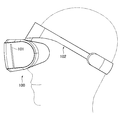
 図1は、本実施の形態におけるHMDの概要の一例を示す図である。具体的には、図1は、HMD100をユーザの頭部に装着した場合におけるHMD100の側面図の概要の一例を示す。 FIG. 1 is a diagram showing an example of an outline of the HMD in the present embodiment. Specifically, FIG. 1 shows an example of an outline of a side view of the HMD 100 when the HMD 100 is worn on the user's head.
 図1に示すようにHMD100は、取得した画像情報に応じて表示パネルは3次元画像を表示する表示パネル101を有する。具体的には、例えば、表示パネル101は、右側領域に右目用の画像を表示し、左側領域に左目用の画像を表示する。なお、表示パネル101は、上記に限定されず、例えば、フレームシーケンシャル方式等の他の方式で3次元画像を表示するように構成してもよい。また、表示パネル101は、例えば、液晶表示パネル101、または、有機EL表示パネル101等で構成する。また、HMD100は、例えば、表示パネル101に表示された画像をユーザの目に案内するとともに、当該画像に対応する虚像を当該ユーザに視認させる光学系と、当該光学系に含まれるレンズまたは表示パネル101を移動することにより、当該虚像がユーザに視認される距離を表す虚像距離を変更する距離変更部を有するが、当該光学系や距離変更部の更なる詳細については後述する。 As shown in FIG. 1, the HMD 100 includes a display panel 101 that displays a three-dimensional image in accordance with the acquired image information. Specifically, for example, the display panel 101 displays a right-eye image in the right region and a left-eye image in the left region. The display panel 101 is not limited to the above, and may be configured to display a three-dimensional image by another method such as a frame sequential method. Further, the display panel 101 is constituted by, for example, a liquid crystal display panel 101, an organic EL display panel 101, or the like. Further, the HMD 100, for example, guides an image displayed on the display panel 101 to the user's eyes and makes the user visually recognize a virtual image corresponding to the image, and a lens or a display panel included in the optical system. A distance changing unit that changes a virtual image distance representing a distance at which the virtual image is visually recognized by the user by moving 101, will be described later in detail.
 当該HMD100は、例えば、ユーザの頭部にHMD100を装着するための装着バンド102を有する。なお、上記HMD100の構成は一例であって、本実施の形態は上記に限定されるものではない。 The HMD 100 includes, for example, a mounting band 102 for mounting the HMD 100 on the user's head. The configuration of the HMD 100 is an example, and the present embodiment is not limited to the above.
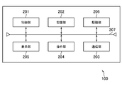
 次に、本実施の形態におけるHMD100のハードウェア構成の一例について説明する。図2は、HMDのハードウェア構成の一例について説明するための図である。図2に示すように、HMD100は、例えば、制御部201、記憶部202、通信部203、操作部204、表示部205、駆動部206を有する。なお、制御部201、記憶部202、通信部203、操作部204、表示部205、駆動部206は、内部バス207により互いに接続される。 Next, an example of the hardware configuration of the HMD 100 in the present embodiment will be described. FIG. 2 is a diagram for explaining an example of the hardware configuration of the HMD. As illustrated in FIG. 2, the HMD 100 includes, for example, a control unit 201, a storage unit 202, a communication unit 203, an operation unit 204, a display unit 205, and a drive unit 206. Note that the control unit 201, the storage unit 202, the communication unit 203, the operation unit 204, the display unit 205, and the drive unit 206 are connected to each other via an internal bus 207.
 制御部201は、例えば、CPU、MPU等であって、記憶部202に格納されたプログラムに従って動作する。記憶部202は、例えば、ROMやRAM等の情報記録媒体で構成され、制御部201によって実行されるプログラムを保持する情報記録媒体である。また、記憶部202は、制御部201のワークメモリとしても動作する。なお、当該プログラムは、例えば、ネットワークを介して、ダウンロードされて提供されてもよいし、または、CD-ROMやDVD-ROM、半導体メモリ等のコンピュータで読み取り可能な各種の情報記録媒体によって提供されてもよい。 The control unit 201 is, for example, a CPU or MPU, and operates according to a program stored in the storage unit 202. The storage unit 202 is an information recording medium configured by an information recording medium such as a ROM or a RAM, and holds a program executed by the control unit 201. The storage unit 202 also operates as a work memory for the control unit 201. Note that the program may be provided by being downloaded via a network, for example, or may be provided by various computer-readable information recording media such as a CD-ROM, a DVD-ROM, and a semiconductor memory. May be.
 通信部203は、当該HMD100を、ネットワークを介して、他の情報処理装置(例えば、ゲーム機器やサーバ等)(図示なし)と接続する。操作部204は、例えば、ボタンやコントローラ等で構成され、ユーザの指示操作に応じて、当該指示操作の内容を制御部201に出力する。表示部205は、上記表示パネル101に相当し、制御部201からの指示に従い、情報を表示する。 The communication unit 203 connects the HMD 100 to another information processing apparatus (for example, a game machine or a server) (not shown) via a network. The operation unit 204 includes, for example, a button, a controller, and the like, and outputs the content of the instruction operation to the control unit 201 in accordance with a user instruction operation. A display unit 205 corresponds to the display panel 101 and displays information in accordance with an instruction from the control unit 201.
 駆動部206は、例えば、モータ(図示なし)及び当該モータに駆動電流を供給するドライバ(図示なし)を含む。ドライバは、制御部201からの指示に従いモータに駆動電流を供給し、これにより、当該モータが回転される。表示部205は、ギヤ部(図示なし)等を介してモータに接続され、モータの回転により表示部205を移動されるように支持される。言い換えれば、モータの回転により表示部205が移動し、後述する虚像距離が変更される。なお、上記においては一例として、駆動部206がモータを回転させることにより表示部205を移動させる場合について説明したが、例えば、光学系を構成するレンズを移動させる等、本実施の形態は虚像距離を変更することができる限り、上記構成に限定されるものではない。 The drive unit 206 includes, for example, a motor (not shown) and a driver (not shown) that supplies a drive current to the motor. The driver supplies a drive current to the motor in accordance with an instruction from the control unit 201, whereby the motor is rotated. The display unit 205 is connected to a motor via a gear unit (not shown) or the like, and is supported so that the display unit 205 is moved by the rotation of the motor. In other words, the display unit 205 is moved by the rotation of the motor, and a virtual image distance to be described later is changed. In the above description, the case where the display unit 205 is moved by rotating the motor by the driving unit 206 has been described as an example. However, for example, the present embodiment is based on the virtual image distance, such as moving a lens constituting the optical system. As long as it can be changed, it is not limited to the said structure.
 なお、図2に示したHMD100の構成は、一例であってこれに限定されるものではない。例えば、HMD100は、例えば、カメラを有し、当該カメラからの撮像情報に応じて後述するユーザの視線方向を表す視線方向情報を取得できるように構成してもよい。 Note that the configuration of the HMD 100 shown in FIG. 2 is an example, and the present invention is not limited to this. For example, the HMD 100 may include a camera, for example, and may be configured to acquire line-of-sight direction information representing a user's line-of-sight direction, which will be described later, in accordance with imaging information from the camera.
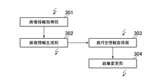
 次に、本実施の形態におけるHMD100の制御部201の機能的構成の一例について説明する。図3は、HMDの制御部の機能的構成の主な一例を示す図である。図3に示すように、HMD100は、機能的に、例えば、画像情報取得部301、画像情報生成部302、奥行き情報取得部303、距離変更部304を含む。 Next, an example of a functional configuration of the control unit 201 of the HMD 100 in the present embodiment will be described. FIG. 3 is a diagram illustrating a main example of a functional configuration of the control unit of the HMD. As illustrated in FIG. 3, the HMD 100 functionally includes, for example, an image information acquisition unit 301, an image information generation unit 302, a depth information acquisition unit 303, and a distance change unit 304.
 画像情報取得部301は、画像情報を取得する。具体的には、例えば、画像情報取得部301は、外部の情報処理装置(例えば、ゲーム機器やサーバ)(図示なし)等から画像情報を取得するように構成してもよいし、記憶部202に記憶された画像情報を取得するように構成してもよい。 The image information acquisition unit 301 acquires image information. Specifically, for example, the image information acquisition unit 301 may be configured to acquire image information from an external information processing apparatus (for example, a game machine or server) (not shown), or the storage unit 202. The image information stored in the memory may be acquired.
 画像情報生成部302は、画像情報取得部301が取得した画像情報に基づき、例えば、1フレーム毎に表示パネル101に表示するフレーム画像を生成する。当該フレーム画像は、表示パネル101に3次元画像を表示するためのフレーム画像であり、上記のように、例えば、右目用のフレーム画像及び左目用のフレーム画像、または、フレームシーケンシャル方式で表示するためのフレーム画像に相当する。そして、表示パネル101は、生成されたフレーム画像を表示する。 The image information generation unit 302 generates a frame image to be displayed on the display panel 101 for each frame, for example, based on the image information acquired by the image information acquisition unit 301. The frame image is a frame image for displaying a three-dimensional image on the display panel 101. For example, the frame image is displayed in a frame image for the right eye and a frame image for the left eye or a frame sequential method as described above. Corresponds to the frame image. Then, the display panel 101 displays the generated frame image.
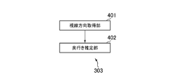
 奥行き情報取得部303は、当該フレーム画像に対応する奥行き情報を取得する。ここで、奥行き情報は、例えば、ユーザの視認する対象物の奥行き、例えば、ユーザの両目の間の中心点から虚像である視認対象物への距離に相当する。具体的には、例えば、奥行き情報取得部303は、図4に示すように視線方向取得部401と、奥行き推定部402を有する。 The depth information acquisition unit 303 acquires depth information corresponding to the frame image. Here, the depth information corresponds to, for example, the depth of the object visually recognized by the user, for example, the distance from the center point between the user's eyes to the visually recognized object that is a virtual image. Specifically, for example, the depth information acquisition unit 303 includes a line-of-sight direction acquisition unit 401 and a depth estimation unit 402 as illustrated in FIG.
 視線方向取得部401は、例えば、ユーザの両目の視線方向を表す視線方向情報を取得する。具体的には、例えば、当該視線方向情報は、ユーザの各目の位置から視認対象への各角度に相当する。奥行き推定部402は、当該視線方向に基づいて、ユーザの視認する対象物の奥行き(例えば、ユーザの両目の間の中心点から虚像である視認対象物への距離に相当する)を推定し、奥行き情報として取得する。より具体的には、例えば、奥行き推定部402は、ユーザの両目の間の距離と、それぞれの視線の角度から奥行きを算出する。なお、ユーザの両目の距離は、例えば、HMD100においてユーザがそれぞれの目を当てるそれぞれの開口部の中心間の距離等に相当する。なお、上記奥行き情報の取得は一例であって、本実施の形態はこれに限られるものではない。例えば、視線方向から視認している対象物を特定し、その視差から奥行きを推定してもよい。視線方向情報の取得等については、例えば、視線方向をリアルタイムに検出するEye Tracking(Gaze Tracking)等として周知であるため、更なる詳細については説明を省略する。 The line-of-sight direction acquisition unit 401 acquires line-of-sight direction information representing the line-of-sight directions of both eyes of the user, for example. Specifically, for example, the line-of-sight direction information corresponds to each angle from the position of each eye of the user to the visual recognition target. The depth estimation unit 402 estimates the depth of the object visually recognized by the user (for example, corresponding to the distance from the center point between the eyes of the user to the visual object that is a virtual image) based on the line-of-sight direction, Obtained as depth information. More specifically, for example, the depth estimation unit 402 calculates the depth from the distance between both eyes of the user and the angle of each line of sight. Note that the distance between the eyes of the user corresponds to, for example, the distance between the centers of the openings where the user hits each eye in the HMD 100. The acquisition of the depth information is an example, and the present embodiment is not limited to this. For example, an object viewed from the line-of-sight direction may be specified, and the depth may be estimated from the parallax. The acquisition of the gaze direction information is well known as, for example, EyeETracking (Gaze す る Tracking) for detecting the gaze direction in real time, and the description of further details is omitted.
 また、奥行き推定部402は、例えば、画像情報とともに、当該画像情報に含まれる各対象物等の奥行き情報を表すあらかじめ設定されたいわゆるDepthマップを取得し、当該Depthマップと視線方向情報に基づいて奥行き情報を取得するように構成してもよい。更に、例えば、視線方向取得部401を省略し、Depthマップを用いて、例えば、表示される画像の中央部等、所定の代表点に基づく奥行き情報を取得するように構成してもよい。なお、この場合、Depthマップは当該代表点の奥行き情報のみの奥行き情報を含むように構成してもよい。また、当該Depthマップは、画像情報を生成等する場合にあらかじめ生成され設定されるものであり、例えば、画像情報取得部301が、画像情報とともに取得するように構成する。 In addition, the depth estimation unit 402 acquires, for example, a preset so-called Depth map that represents depth information of each object included in the image information together with the image information, and based on the Depth map and the line-of-sight direction information. You may comprise so that depth information may be acquired. Further, for example, the line-of-sight direction acquisition unit 401 may be omitted, and the depth information based on a predetermined representative point such as the center of the displayed image may be acquired using a depth map. In this case, the depth map may be configured to include only depth information of the representative point. The depth map is generated and set in advance when image information is generated. For example, the image information acquisition unit 301 is configured to acquire the image information together with the image information.
 距離変更部304は、当該奥行き情報に基づいて、駆動部206に指示することによりユーザが視認する虚像の虚像距離を変更する。つまり、距離変更部は、例えば、1フレーム前の視認対象物の奥行きに基づいて、虚像距離を変更する。なお、本実施の形態は1フレーム前の視認対象物の奥行きに限られず、数フレーム前の奥行きや、数フレームにおける奥行きの統計値(例えば、平均値)に基づいて、虚像距離を変更するように構成してもよい。具体的には、説明の簡略化のために、一例として、光学系が片目毎に1枚のレンズで形成され、距離変更部304が、表示パネル101を移動して、当該レンズと表示パネル101間の距離を変更する場合を例として下記に説明する。 The distance changing unit 304 changes the virtual image distance of the virtual image visually recognized by the user by instructing the driving unit 206 based on the depth information. That is, the distance changing unit changes the virtual image distance based on, for example, the depth of the visually recognized object one frame before. Note that the present embodiment is not limited to the depth of the visually recognized object one frame before, and the virtual image distance is changed based on the depth several frames before and the statistical value (for example, the average value) of the depth in several frames. You may comprise. Specifically, for the sake of simplification of description, as an example, the optical system is formed by one lens for each eye, and the distance changing unit 304 moves the display panel 101 to move the lens and the display panel 101. An example of changing the distance between them will be described below.
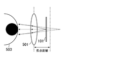
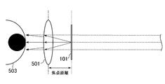
 図5A及び図5Bは、本実施の形態における虚像距離の変更を説明するための図である。距離変更部304は、例えば、取得された奥行き情報が大きい場合(つまり、遠くに視認される虚像を提示する場合)については、図5Bに示すように表示パネル101をレンズ501から遠ざけるように移動し、一方、奥行き情報が小さい場合(つまり、近くに視認される虚像を提示する場合)については、図5Aに示すように表示パネル101をレンズ501に近づけるように移動する。なお、当該移動には、周知のモータやギヤ等が用いられることから、移動の機構自体については、説明を省略する。なお、図5A及び図5Bに示すように、HMD100においては、例えば、ユーザの目503毎にレンズ501が設けられ、当該レンズ501を介して、ユーザは表示パネル101に表示された画像をレンズ501と表示パネル501との間の距離に基づく虚像距離において視認する。なお、図5Aにおける矢印502は、表示パネル101の移動方向を示す。 FIG. 5A and FIG. 5B are diagrams for explaining the change of the virtual image distance in the present embodiment. The distance changing unit 304 moves the display panel 101 away from the lens 501 as shown in FIG. 5B, for example, when the acquired depth information is large (that is, when presenting a virtual image viewed in the distance). On the other hand, when the depth information is small (that is, when a virtual image visually recognized nearby is presented), the display panel 101 is moved closer to the lens 501 as shown in FIG. 5A. In addition, since a well-known motor, a gear, etc. are used for the said movement, description is abbreviate | omitted about the mechanism of movement itself. As shown in FIGS. 5A and 5B, in the HMD 100, for example, a lens 501 is provided for each user's eye 503, and the user displays an image displayed on the display panel 101 via the lens 501. And a virtual image distance based on the distance between the display panel 501 and the display panel 501. Note that an arrow 502 in FIG. 5A indicates the moving direction of the display panel 101.
 ここで、一般に、虚像距離を焦点距離のk倍にするためには、レンズ501と表示パネル101の間隔を焦点距離の1/kだけレンズ501側に移動させる必要がある。例えば、図6に示すように、焦点距離を5cmとする場合であって、虚像距離を1mから∞まで変化させる場合、表示パネル101を2.5mmの移動範囲が必要となる。したがって、この場合、距離変更部304が、表示パネル101を2.5mmの範囲で移動することができるように構成すればよい。このように構成することで、例えば、図7A及び図7Bに示すように、虚像距離を所定の近距離から、無限遠にまで変更することができる。ここで、図7Aが近距離の場合を表し、図7Bが無限遠の場合の模式図を示す。 Here, in general, in order to make the virtual image distance k times the focal length, it is necessary to move the distance between the lens 501 and the display panel 101 toward the lens 501 by 1 / k of the focal length. For example, as shown in FIG. 6, when the focal length is 5 cm and the virtual image distance is changed from 1 m to ∞, the display panel 101 needs to move within a range of 2.5 mm. Therefore, in this case, the distance changing unit 304 may be configured to be able to move the display panel 101 within a range of 2.5 mm. With this configuration, for example, the virtual image distance can be changed from a predetermined short distance to infinity as shown in FIGS. 7A and 7B. Here, FIG. 7A shows a case of a short distance, and FIG. 7B shows a schematic diagram of a case of infinity.
 なお、上記においては、主に光学系が目毎に1のレンズ501で構成される場合について説明したが、複数のレンズで構成してもよい。この場合の動作は、上記1のレンズで光学系を構成する場合と異なるが、奥行き情報に応じて虚像距離が変更されるように構成することはいうまでもない。 In the above description, the case where the optical system is mainly composed of one lens 501 for each eye has been described. However, the optical system may be composed of a plurality of lenses. The operation in this case is different from that in the case where the optical system is configured by the lens 1 described above, but it goes without saying that the virtual image distance is changed according to the depth information.
 次に、本実施の形態におけるHMD100の処理のフローの概要の一例について説明する。図8は、本実施の形態にHMD100の処理のフローの概要の一例を示す図である。 Next, an example of an outline of the processing flow of the HMD 100 in the present embodiment will be described. FIG. 8 is a diagram showing an example of an outline of the processing flow of the HMD 100 in the present embodiment.
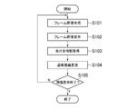
 図8に示すように、画像情報生成部302は、画像情報取得部301が取得した画像情報に基づき、例えば、1フレーム毎に表示パネル101に表示するフレーム画像を生成する(S101)。表示パネル101は生成されたフレーム画像を表示する(S102)。奥行き情報取得部303は、当該フレーム画像に対応する奥行き情報を取得する(S103)。上記のように、当該奥行き情報は、例えば、視線方向により推定されるように構成してもよいし、Depthマップに基づいて取得されるように構成してもよい。距離変更部304は、当該奥行き情報に基づいて、虚像距離を変更する(S104)。 As shown in FIG. 8, the image information generation unit 302 generates a frame image to be displayed on the display panel 101, for example, every frame based on the image information acquired by the image information acquisition unit 301 (S101). The display panel 101 displays the generated frame image (S102). The depth information acquisition unit 303 acquires depth information corresponding to the frame image (S103). As described above, the depth information may be configured to be estimated based on the line-of-sight direction, for example, or may be configured to be acquired based on the Depth map. The distance changing unit 304 changes the virtual image distance based on the depth information (S104).
 次に、画像情報生成部302は、全ての画像情報の表示が終了したか否かを判断する(S105)。具体的には、例えば、画像情報生成部302は、ユーザにより画像情報の表示が終了した場合や、最後のフレーム画像の生成が終了している場合に、全ての画像情報の表示が終了したと判断する。 Next, the image information generation unit 302 determines whether or not the display of all image information has been completed (S105). Specifically, for example, the image information generation unit 302 determines that the display of all image information has been completed when the display of the image information has been completed by the user or the generation of the last frame image has been completed. to decide.
 そして、画像情報生成部302が全ての画像情報の表示が終了していないと判断した場合には、S101に戻り、次に表示パネル101に表示するフレーム画像を表示する等、S102乃至S104の処理が繰り返し行われる。一方、画像情報生成部302が全ての画像情報の表示が終了したと判断した場合には、処理を終了する。 If the image information generation unit 302 determines that the display of all the image information has not been completed, the process returns to S101, and the frame image to be displayed on the display panel 101 is displayed next. Is repeated. On the other hand, when the image information generation unit 302 determines that the display of all the image information has been completed, the process ends.
 なお、上記処理のフローは一例であって、本実施の形態は、上記に限定されるものではない。例えば、上記フローにおいては、主に1フレーム画像毎に対応する奥行き情報に基づいて、表示パネル101を移動する場合について説明したが、所定の数のフレーム画像毎(例えば、所定数のフレーム画像毎)に、奥行き情報を取得して、表示パネル101を移動するように構成してもよいことは上記のとおりである。また、奥行き情報の推定に、上述のDepthマップを用いる場合には、例えば、S102以前に奥行き情報を取得するように構成してもよい。 Note that the flow of the above process is an example, and the present embodiment is not limited to the above. For example, in the above flow, the case where the display panel 101 is moved based mainly on the depth information corresponding to each frame image has been described. However, every predetermined number of frame images (for example, every predetermined number of frame images). ), The depth information may be acquired and the display panel 101 may be moved as described above. Further, when the above-described depth map is used for estimation of depth information, for example, the depth information may be acquired before S102.
 本実施の形態によれば、例えば、対象物の実際の奥行き、視認対象物が撮影された場合におけるカメラと当該対象物の距離、または、コンピュータグラフィックスにおいて想定されている対象物の距離等に応じた虚像距離に視認対象物を視認させることができるヘッドマウントディスプレイ等を実現することができる。これにより、例えば、ユーザがより自然に視認対象物を視認することができ、また、より現実感のある視認対象物の視認が可能となる。 According to the present embodiment, for example, the actual depth of the object, the distance between the camera and the object when the visually recognized object is photographed, or the distance between the object assumed in computer graphics, etc. It is possible to realize a head mounted display or the like that can visually recognize a visually recognized object at a corresponding virtual image distance. Thereby, for example, the user can visually recognize the visually recognized object more naturally, and the visually recognized visually recognized object can be visually recognized.
 本発明は、上記実施の形態に限定されるものではなく、上記実施の形態で示した構成と実質的に同一の構成、同一の作用効果を奏する構成又は同一の目的を達成することができる構成で置き換えてもよい。 The present invention is not limited to the above-described embodiment, and is substantially the same configuration as the configuration shown in the above-described embodiment, a configuration that exhibits the same operational effects, or a configuration that can achieve the same purpose. May be replaced.
 例えば、上記においては、主に、奥行き情報に応じて虚像距離を一例として1mから∞まで動的に変更する場合について説明したが、例えば、所定の設定モードを設けて、虚像距離の範囲を制限するように構成してもよい。より具体的には、第1の設定モードにおいては、1mから10mまでの範囲に制限し、第2の設定モードにおいては、10mから無限遠方までの範囲となるように制限してもよい。この場合、各ユーザの希望に応じた範囲で、虚像を視認することができる。より具体的には、例えば、ユーザが近視の場合には、上記第1の設定モードを用い、ユーザが遠視の場合には、上記第2の設定モードを用いる等により、ユーザの快適に視認可能な虚像距離で対象物を視認することができる。 For example, in the above description, the case where the virtual image distance is dynamically changed from 1 m to ∞ as an example according to the depth information has been described. For example, a predetermined setting mode is provided to limit the range of the virtual image distance. You may comprise. More specifically, the first setting mode may be limited to a range from 1 m to 10 m, and the second setting mode may be limited to a range from 10 m to infinity. In this case, the virtual image can be visually recognized within a range according to each user's request. More specifically, for example, when the user is nearsighted, the first setting mode is used, and when the user is farsighted, the second setting mode is used, so that the user can comfortably view. It is possible to visually recognize an object at a virtual image distance.
 また、奥行き情報に奥行き情報に応じて、奥行き情報に所定の値を乗算した虚像距離に変更するモードを有するように構成してもよい。例えば、奥行き情報が1mのものは10mの虚像距離に、奥行き情報が10mのものは100mの虚像距離にするなどである。また、例えば、奥行き情報が所定の値以上の場合には、より遠くの虚像距離に、奥行き情報が所定の値以下の場合には、より近くの虚像距離に変更するように構成してもよい。これにより、画像情報によっては、より迫力のある視認等が実現される場合がある。 Further, a mode may be provided in which the depth information is changed to a virtual image distance obtained by multiplying the depth information by a predetermined value in accordance with the depth information. For example, when the depth information is 1 m, the virtual image distance is 10 m, and when the depth information is 10 m, the virtual image distance is 100 m. Further, for example, when the depth information is equal to or greater than a predetermined value, the distance may be changed to a farther virtual image distance, and when the depth information is equal to or smaller than the predetermined value, the distance may be changed to a closer virtual image distance. . Thereby, depending on the image information, more powerful visual recognition may be realized.
 また、画像情報が表すシーンが変更したか否かを判定し、シーン変更後所定の期間は、虚像距離の変更を行わず、所定の期間内における視線方向に応じて虚像距離を変更するように構成してもよい。これにより、例えば、無限遠から急に近距離に虚像距離が移動するシーンなどにおいても、ユーザはより快適に視認対象を視認することができる。 Further, it is determined whether or not the scene represented by the image information has been changed, and the virtual image distance is changed according to the line-of-sight direction within the predetermined period without changing the virtual image distance for a predetermined period after the scene change. It may be configured. Thereby, for example, even in a scene where the virtual image distance suddenly moves from infinity to a short distance, the user can visually recognize the visual recognition object more comfortably.
 また、距離変更部304は、視線が移動した後に虚像距離を変更し、視線の移動中は、虚像距離の変更を行わないように構成してもよい。具体的には、例えば、視線方向取得部401が視線方向の移動を検出している間には、虚像距離の変更を行わず、視線の移動が停止した後に虚像距離の変更を行う。具体的には、例えば、所定期間視線の移動がない場合に虚像距離の変更を行う。また、所定の距離以上視線が移動した場合に、虚像距離の変更を行わないように構成してもよい。これにより、シーンによっては、ユーザがより快適に視認対象を視認することができる。 Further, the distance changing unit 304 may be configured to change the virtual image distance after the line of sight moves, and not to change the virtual image distance while the line of sight moves. Specifically, for example, the virtual image distance is not changed while the visual line direction acquisition unit 401 detects the movement of the visual line direction, and the virtual image distance is changed after the movement of the visual line is stopped. Specifically, for example, the virtual image distance is changed when there is no movement of the line of sight for a predetermined period. Further, when the line of sight moves beyond a predetermined distance, the virtual image distance may not be changed. Thereby, depending on a scene, a user can visually recognize a visual recognition object more comfortably.
 更に、上記においては、主に、画像情報の生成や、奥行き情報の推定の処理等をHMD100で行う場合について説明したが、当該処理等は、HMD100に接続される情報処理装置(ゲーム機器やサーバ等)により行われるように構成してもよい。具体的には、例えば、HMD100において視差方向情報を取得し、当該視差方向を当該情報処理装置等に送信し、情報処理装置において生成された奥行き情報をHMD100が取得するように構成してもよい。 Furthermore, in the above description, the case where image information generation, depth information estimation processing, and the like are mainly performed by the HMD 100 has been described. However, the processing is performed by an information processing apparatus (game device or server) connected to the HMD 100. Etc.). Specifically, for example, the HMD 100 may acquire parallax direction information, transmit the parallax direction to the information processing apparatus or the like, and the HMD 100 may acquire depth information generated in the information processing apparatus. .
 また、上記においては、虚像距離変更装置として、HMD100を例として説明したが、虚像距離変更装置は、例えば、電子ファインダー、デジタル化された顕微鏡接眼部、電子双眼鏡など、光学系を通して光源(拡散反射光)を見るデバイスを含む。 In the above description, the HMD 100 is described as an example of the virtual image distance changing device. However, the virtual image distance changing device is a light source (diffusion) through an optical system such as an electronic finder, a digitized microscope eyepiece, and electronic binoculars. Includes devices that see reflected light.
 なお、上記各変形例は、例えば、Depthマップを利用しつつ、ユーザの視線移動中は虚像距離を変更しないように構成するなど、互いに矛盾しない限り組み合わせて用いてもよい。 In addition, you may use each said modification as long as it does not contradict each other, for example, it is comprised so that a virtual image distance may not be changed while a user's eyes | visual_axis movement is using a Depth map.

Claims (11)

  1.  画像情報に応じた画像を表示する表示パネルと、
     前記表示パネルに表示された画像をユーザの眼に案内するとともに、該画像に応じた虚像を該ユーザに視認させる光学系と、
     前記表示パネルに表示されるとともに該ユーザの視認対象である視認対象物の奥行きを表す奥行き情報を取得する奥行き情報取得手段と、
     前記奥行き情報に応じて、前記虚像が前記ユーザに視認される距離を表す虚像距離を変更する距離変更手段と、
     を含むことを特徴とする虚像距離変更装置。
    A display panel that displays images according to image information;
    An optical system for guiding the image displayed on the display panel to the user's eyes and causing the user to visually recognize a virtual image corresponding to the image;
    Depth information acquisition means for acquiring depth information displayed on the display panel and representing the depth of the visual target that is the visual target of the user;
    Distance changing means for changing a virtual image distance representing a distance at which the virtual image is visually recognized by the user according to the depth information;
    A virtual image distance changing device.
  2.  前記奥行き情報取得手段は、
     前記ユーザの視線方向を表す視線方向情報を取得する視線方向取得手段と、
     前記取得された視線方向情報に基づいて、前記奥行きを推定する奥行き推定手段と、
     を含むことを特徴とする請求項1に記載の虚像距離変更装置。
    The depth information acquisition means includes
    Gaze direction acquisition means for acquiring gaze direction information representing the gaze direction of the user;
    Depth estimation means for estimating the depth based on the acquired gaze direction information;
    The virtual image distance changing device according to claim 1, comprising:
  3.  前記奥行き情報は、前記画像情報に応じてあらかじめ設定されていることを特徴とする請求項1に記載の虚像距離変更装置。 2. The virtual image distance changing device according to claim 1, wherein the depth information is preset according to the image information.
  4.  前記奥行き情報は、前記画像情報の中央部における所定の代表点に基づくことを特徴とする請求項3に記載の虚像距離変更装置。 4. The virtual image distance changing device according to claim 3, wherein the depth information is based on a predetermined representative point in a central portion of the image information.
  5.  前記距離変更手段は、前記ユーザの視線方向の移動後に前記虚像距離を変更することを特徴とする請求項1に記載の虚像距離変更装置。 2. The virtual image distance changing device according to claim 1, wherein the distance changing unit changes the virtual image distance after the user moves in the line-of-sight direction.
  6.  前記距離変更手段は、所定の範囲内で前記虚像距離を変更することを特徴とする請求項1に記載の虚像距離変更装置。 2. The virtual image distance changing device according to claim 1, wherein the distance changing means changes the virtual image distance within a predetermined range.
  7.  前記距離変更手段は、前記画像情報の表すシーンが変更した場合には、前記シーン変更後所定の期間経過後に前記虚像距離を変更することを特徴とする請求項1に記載の虚像距離変更装置。 2. The virtual image distance changing device according to claim 1, wherein when the scene represented by the image information is changed, the distance changing unit changes the virtual image distance after a predetermined period has elapsed after the scene change.
  8.  前記距離変更手段は、前記表示パネルまたは前記光学系に含まれるレンズを移動させることにより、前記虚像距離を変更することを特徴とする請求項1に記載の虚像距離変更装置。 2. The virtual image distance changing device according to claim 1, wherein the distance changing means changes the virtual image distance by moving a lens included in the display panel or the optical system.
  9.  前記虚像距離変更装置は、ヘッドマウントディスプレイであることを特徴とする請求項1に記載の虚像距離変更装置。 The virtual image distance changing device according to claim 1, wherein the virtual image distance changing device is a head mounted display.
  10.  画像情報に応じた画像を表示し、
     前記表示パネルに表示された画像をユーザの眼に案内するとともに、該画像に応じた虚像を該ユーザに視認させ、
     前記表示パネルに表示されるとともに該ユーザの視認対象である視認対象物の奥行きを表す奥行き情報を取得し、
     前記奥行き情報に応じて、前記虚像が前記ユーザに視認される距離を表す虚像距離を変更する、
     ことを特徴とする虚像距離変更方法。
    Display the image according to the image information,
    While guiding the image displayed on the display panel to the user's eyes, let the user visually recognize a virtual image corresponding to the image,
    Depth information that is displayed on the display panel and represents the depth of the visual target that is the visual target of the user,
    According to the depth information, a virtual image distance representing a distance at which the virtual image is visually recognized by the user is changed.
    A virtual image distance changing method characterized by that.
  11.  画像情報に応じた画像を表示する表示パネルと、前記表示パネルに表示された画像をユーザの眼に案内するとともに、該画像に応じた虚像を該ユーザに視認させる光学系と、を含む虚像距離変更装置に関するプログラムであって、
     前記表示パネルに表示されるとともに該ユーザの視認対象である視認対象物の奥行きを表す奥行き情報を取得する奥行き情報取得手段、及び、
     前記奥行き情報に応じて、前記虚像が前記ユーザに視認される距離を表す虚像距離を変更する距離変更手段、
     としてコンピュータを機能させることを特徴とするプログラム。
    A virtual image distance comprising: a display panel that displays an image according to image information; and an optical system that guides the image displayed on the display panel to a user's eyes and causes the user to visually recognize a virtual image corresponding to the image A program related to a change device,
    Depth information acquisition means for acquiring depth information displayed on the display panel and representing the depth of the visual target that is the visual target of the user; and
    Distance changing means for changing a virtual image distance representing a distance at which the virtual image is visually recognized by the user according to the depth information;
    A program characterized by causing a computer to function.
PCT/JP2015/074108 2014-10-23 2015-08-26 Virtual-image-distance changing device, method for changing virtual image distance, program WO2016063620A1 (en)

Priority Applications (4)

Application Number Priority Date Filing Date Title
JP2016555122A JP6307170B2 (en) 2014-10-23 2015-08-26 Virtual image distance changing device, virtual image distance changing method, program
CN201580056030.7A CN107077002A (en) 2014-10-23 2015-08-26 Virtual image distance changes device, virtual image Range Change Method and program
US15/502,903 US20170255021A1 (en) 2014-10-23 2015-08-26 Virtual image distance changing device, virtual image distance changing method, and program
EP15852667.3A EP3211471A4 (en) 2014-10-23 2015-08-26 Virtual-image-distance changing device, method for changing virtual image distance, program

Applications Claiming Priority (2)

Application Number Priority Date Filing Date Title
JP2014216656 2014-10-23
JP2014-216656 2014-10-23

Publications (1)

Publication Number Publication Date
WO2016063620A1 true WO2016063620A1 (en) 2016-04-28

Family

ID=55760668

Family Applications (1)

Application Number Title Priority Date Filing Date
PCT/JP2015/074108 WO2016063620A1 (en) 2014-10-23 2015-08-26 Virtual-image-distance changing device, method for changing virtual image distance, program

Country Status (5)

Country Link
US (1) US20170255021A1 (en)
EP (1) EP3211471A4 (en)
JP (1) JP6307170B2 (en)
CN (1) CN107077002A (en)
WO (1) WO2016063620A1 (en)

Cited By (2)

* Cited by examiner, † Cited by third party
Publication number Priority date Publication date Assignee Title
JP2018045217A (en) * 2016-09-14 2018-03-22 伊藤 克之 Distant-view image display device
WO2021024827A1 (en) * 2019-08-08 2021-02-11 ソニー株式会社 Surgical image display system, image processing device, and image processing method

Families Citing this family (12)

* Cited by examiner, † Cited by third party
Publication number Priority date Publication date Assignee Title
CN108066981A (en) * 2016-11-12 2018-05-25 金德奎 A kind of AR or MR method for gaming identified based on position and image and system
EP3776062B1 (en) 2018-05-29 2023-07-05 Apple Inc. Optical system for head-mounted display
CN111479104A (en) * 2018-12-21 2020-07-31 托比股份公司 Method for calculating line-of-sight convergence distance
CN109683336A (en) * 2019-01-14 2019-04-26 杨铭轲 Display device and its display methods
CN110188643A (en) * 2019-05-21 2019-08-30 北京市商汤科技开发有限公司 A kind of information display method and device, storage medium
CN110308560B (en) * 2019-07-03 2022-09-30 南京玛克威信息科技有限公司 Control method of VR equipment
CN112241068A (en) * 2019-07-18 2021-01-19 三星电子株式会社 Image display device capable of multi-depth expression
EP4001995A4 (en) * 2019-07-18 2023-11-29 Samsung Electronics Co., Ltd. Image display device capable of expressing multiple depth
CN110840721B (en) * 2019-11-25 2022-04-15 北京耐德佳显示技术有限公司 Near-eye display-based eyesight prevention, control and training method and near-eye display equipment
KR20210091580A (en) 2020-01-14 2021-07-22 삼성전자주식회사 Device and method for 3-dimensional image display
CN113433628A (en) * 2021-06-23 2021-09-24 河南鑫宇光科技股份有限公司 Low-crosstalk single-wavelength optical device
CN114326295B (en) * 2022-03-15 2022-07-19 之江实验室 Femtosecond laser direct writing method for zinc oxide micro-nano pattern

Citations (3)

* Cited by examiner, † Cited by third party
Publication number Priority date Publication date Assignee Title
JP2007267261A (en) * 2006-03-29 2007-10-11 Toshiba Corp Stereoscopic display device
JP2010139901A (en) * 2008-12-15 2010-06-24 Brother Ind Ltd Head mount display
JP2013186641A (en) * 2012-03-07 2013-09-19 Seiko Epson Corp Head-mounted display device and control method of the same

Family Cites Families (8)

* Cited by examiner, † Cited by third party
Publication number Priority date Publication date Assignee Title
JP3787939B2 (en) * 1997-02-27 2006-06-21 コニカミノルタホールディングス株式会社 3D image display device
AU2439001A (en) * 1999-12-16 2001-06-25 Reveo, Inc. Three-dimensional volumetric display
EP1784988A1 (en) * 2004-08-06 2007-05-16 University of Washington Variable fixation viewing distance scanned light displays
US9304319B2 (en) * 2010-11-18 2016-04-05 Microsoft Technology Licensing, Llc Automatic focus improvement for augmented reality displays
US20130083003A1 (en) * 2011-09-30 2013-04-04 Kathryn Stone Perez Personal audio/visual system
US9880325B2 (en) * 2013-08-14 2018-01-30 Nvidia Corporation Hybrid optics for near-eye displays
KR102077105B1 (en) * 2013-09-03 2020-02-13 한국전자통신연구원 Apparatus and method for designing display for user interaction in the near-body space
JP5420793B1 (en) * 2013-09-10 2014-02-19 テレパシー インク Head-mounted display with adjustable image viewing distance

Patent Citations (3)

* Cited by examiner, † Cited by third party
Publication number Priority date Publication date Assignee Title
JP2007267261A (en) * 2006-03-29 2007-10-11 Toshiba Corp Stereoscopic display device
JP2010139901A (en) * 2008-12-15 2010-06-24 Brother Ind Ltd Head mount display
JP2013186641A (en) * 2012-03-07 2013-09-19 Seiko Epson Corp Head-mounted display device and control method of the same

Non-Patent Citations (1)

* Cited by examiner, † Cited by third party
Title
See also references of EP3211471A4 *

Cited By (2)

* Cited by examiner, † Cited by third party
Publication number Priority date Publication date Assignee Title
JP2018045217A (en) * 2016-09-14 2018-03-22 伊藤 克之 Distant-view image display device
WO2021024827A1 (en) * 2019-08-08 2021-02-11 ソニー株式会社 Surgical image display system, image processing device, and image processing method

Also Published As

Publication number Publication date
EP3211471A4 (en) 2018-06-20
JPWO2016063620A1 (en) 2017-05-25
EP3211471A1 (en) 2017-08-30
CN107077002A (en) 2017-08-18
US20170255021A1 (en) 2017-09-07
JP6307170B2 (en) 2018-04-04

Similar Documents

Publication Publication Date Title
JP6307170B2 (en) Virtual image distance changing device, virtual image distance changing method, program
JP6983258B2 (en) Near-eye display with enhanced effective eyebox via eye tracking
US10241329B2 (en) Varifocal aberration compensation for near-eye displays
US10726765B2 (en) Using tracking of display device to control image display
EP3526967B1 (en) Non-planar computational displays
US10353207B2 (en) Head-mounted display device and video display system
EP3301545B1 (en) Computer program, object tracking method, and display device
JP5420793B1 (en) Head-mounted display with adjustable image viewing distance
WO2016038997A1 (en) Display device, method for driving display device, and electronic device
JP2014219621A (en) Display device and display control program
US20210201580A1 (en) Artificial reality system with varifocal display of artificial reality content
US11301969B1 (en) Context aware dynamic distortion correction
US10291896B2 (en) Display control methods and apparatuses and display devices
US20210037232A1 (en) Driving method for calculating interpupillary distance and related head-mounted device
JP2016210259A (en) Head-up display
JP2015060071A (en) Image display device, image display method, and image display program
JP2015026286A (en) Display device, display system and control method of display device
CN111722401A (en) Display device, display control method, and display system
JP2019008205A (en) Head-mounted display device
JP2019151205A (en) On-vehicle display device, method for controlling the same, and computer program
US20230254466A1 (en) Control device
JP2019008204A (en) Head-mounted display device
JP2023143437A (en) Control device, control method, and control program
JP2016081463A (en) Display controller, display control method, display control program and projector
CN115668035A (en) Single view display for wearable device

Legal Events

Date Code Title Description
121 Ep: the epo has been informed by wipo that ep was designated in this application

Ref document number: 15852667

Country of ref document: EP

Kind code of ref document: A1

ENP Entry into the national phase

Ref document number: 2016555122

Country of ref document: JP

Kind code of ref document: A

REEP Request for entry into the european phase

Ref document number: 2015852667

Country of ref document: EP

WWE Wipo information: entry into national phase

Ref document number: 2015852667

Country of ref document: EP

NENP Non-entry into the national phase

Ref country code: DE

WWE Wipo information: entry into national phase

Ref document number: 15502903

Country of ref document: US