EP2532852B1 - Procédé de purification d'échappement pour moteur à combustion interne - Google Patents
Procédé de purification d'échappement pour moteur à combustion interne Download PDFInfo
- Publication number
- EP2532852B1 EP2532852B1 EP11801951.2A EP11801951A EP2532852B1 EP 2532852 B1 EP2532852 B1 EP 2532852B1 EP 11801951 A EP11801951 A EP 11801951A EP 2532852 B1 EP2532852 B1 EP 2532852B1
- Authority
- EP
- European Patent Office
- Prior art keywords
- exhaust
- hydrocarbons
- purification
- exhaust purification
- catalyst
- Prior art date
- Legal status (The legal status is an assumption and is not a legal conclusion. Google has not performed a legal analysis and makes no representation as to the accuracy of the status listed.)
- Not-in-force
Links
- 238000000746 purification Methods 0.000 title claims description 418
- 238000000034 method Methods 0.000 title claims description 105
- 238000002485 combustion reaction Methods 0.000 title claims description 26
- 229930195733 hydrocarbon Natural products 0.000 claims description 272
- 150000002430 hydrocarbons Chemical class 0.000 claims description 270
- 239000003054 catalyst Substances 0.000 claims description 257
- 238000002347 injection Methods 0.000 claims description 113
- 239000007924 injection Substances 0.000 claims description 113
- 239000007789 gas Substances 0.000 claims description 107
- 239000004215 Carbon black (E152) Substances 0.000 claims description 78
- 230000009471 action Effects 0.000 claims description 52
- 230000001603 reducing effect Effects 0.000 claims description 51
- 230000008859 change Effects 0.000 claims description 27
- BASFCYQUMIYNBI-UHFFFAOYSA-N platinum Chemical compound [Pt] BASFCYQUMIYNBI-UHFFFAOYSA-N 0.000 claims description 27
- 239000010970 precious metal Substances 0.000 claims description 18
- 238000003860 storage Methods 0.000 claims description 18
- KDLHZDBZIXYQEI-UHFFFAOYSA-N Palladium Chemical compound [Pd] KDLHZDBZIXYQEI-UHFFFAOYSA-N 0.000 claims description 12
- 229910052697 platinum Inorganic materials 0.000 claims description 12
- 239000010948 rhodium Substances 0.000 claims description 12
- 238000004519 manufacturing process Methods 0.000 claims description 9
- IJGRMHOSHXDMSA-UHFFFAOYSA-N Atomic nitrogen Chemical compound N#N IJGRMHOSHXDMSA-UHFFFAOYSA-N 0.000 claims description 8
- 229910052703 rhodium Inorganic materials 0.000 claims description 6
- MHOVAHRLVXNVSD-UHFFFAOYSA-N rhodium atom Chemical compound [Rh] MHOVAHRLVXNVSD-UHFFFAOYSA-N 0.000 claims description 6
- 229910052757 nitrogen Inorganic materials 0.000 claims description 4
- 229910052763 palladium Inorganic materials 0.000 claims description 4
- 229910052783 alkali metal Inorganic materials 0.000 claims description 2
- 150000001340 alkali metals Chemical class 0.000 claims description 2
- 229910052784 alkaline earth metal Inorganic materials 0.000 claims description 2
- 230000007423 decrease Effects 0.000 claims description 2
- 229910052751 metal Inorganic materials 0.000 claims description 2
- 239000002184 metal Substances 0.000 claims description 2
- 229910052761 rare earth metal Inorganic materials 0.000 claims description 2
- 150000002910 rare earth metals Chemical class 0.000 claims description 2
- 239000000446 fuel Substances 0.000 description 104
- QVGXLLKOCUKJST-UHFFFAOYSA-N atomic oxygen Chemical compound [O] QVGXLLKOCUKJST-UHFFFAOYSA-N 0.000 description 19
- 239000001301 oxygen Substances 0.000 description 19
- 229910052760 oxygen Inorganic materials 0.000 description 19
- 150000002823 nitrates Chemical class 0.000 description 18
- 238000007254 oxidation reaction Methods 0.000 description 15
- 229910002651 NO3 Inorganic materials 0.000 description 14
- NHNBFGGVMKEFGY-UHFFFAOYSA-N Nitrate Chemical compound [O-][N+]([O-])=O NHNBFGGVMKEFGY-UHFFFAOYSA-N 0.000 description 14
- 230000001590 oxidative effect Effects 0.000 description 13
- UFHFLCQGNIYNRP-UHFFFAOYSA-N Hydrogen Chemical compound [H][H] UFHFLCQGNIYNRP-UHFFFAOYSA-N 0.000 description 12
- 230000006870 function Effects 0.000 description 12
- 239000001257 hydrogen Substances 0.000 description 12
- 229910052739 hydrogen Inorganic materials 0.000 description 12
- 230000003647 oxidation Effects 0.000 description 11
- -1 radical hydrocarbons Chemical class 0.000 description 10
- 239000002585 base Substances 0.000 description 8
- 238000001816 cooling Methods 0.000 description 6
- RZCJYMOBWVJQGV-UHFFFAOYSA-N 2-naphthyloxyacetic acid Chemical compound C1=CC=CC2=CC(OCC(=O)O)=CC=C21 RZCJYMOBWVJQGV-UHFFFAOYSA-N 0.000 description 5
- 230000012447 hatching Effects 0.000 description 5
- 231100001143 noxa Toxicity 0.000 description 5
- 238000011144 upstream manufacturing Methods 0.000 description 5
- 230000006835 compression Effects 0.000 description 4
- 238000007906 compression Methods 0.000 description 4
- 239000000498 cooling water Substances 0.000 description 4
- 150000002500 ions Chemical class 0.000 description 4
- 239000012948 isocyanate Substances 0.000 description 4
- XEEYBQQBJWHFJM-UHFFFAOYSA-N Iron Chemical compound [Fe] XEEYBQQBJWHFJM-UHFFFAOYSA-N 0.000 description 3
- 238000006243 chemical reaction Methods 0.000 description 3
- 238000010521 absorption reaction Methods 0.000 description 2
- 230000001133 acceleration Effects 0.000 description 2
- 230000004913 activation Effects 0.000 description 2
- 239000011575 calcium Substances 0.000 description 2
- 239000010949 copper Substances 0.000 description 2
- 239000002283 diesel fuel Substances 0.000 description 2
- 230000000694 effects Effects 0.000 description 2
- 239000002828 fuel tank Substances 0.000 description 2
- 150000002828 nitro derivatives Chemical class 0.000 description 2
- 238000006479 redox reaction Methods 0.000 description 2
- 238000002407 reforming Methods 0.000 description 2
- 239000011734 sodium Substances 0.000 description 2
- 238000001179 sorption measurement Methods 0.000 description 2
- OYPRJOBELJOOCE-UHFFFAOYSA-N Calcium Chemical compound [Ca] OYPRJOBELJOOCE-UHFFFAOYSA-N 0.000 description 1
- OKTJSMMVPCPJKN-UHFFFAOYSA-N Carbon Chemical compound [C] OKTJSMMVPCPJKN-UHFFFAOYSA-N 0.000 description 1
- RYGMFSIKBFXOCR-UHFFFAOYSA-N Copper Chemical compound [Cu] RYGMFSIKBFXOCR-UHFFFAOYSA-N 0.000 description 1
- DGAQECJNVWCQMB-PUAWFVPOSA-M Ilexoside XXIX Chemical compound C[C@@H]1CC[C@@]2(CC[C@@]3(C(=CC[C@H]4[C@]3(CC[C@@H]5[C@@]4(CC[C@@H](C5(C)C)OS(=O)(=O)[O-])C)C)[C@@H]2[C@]1(C)O)C)C(=O)O[C@H]6[C@@H]([C@H]([C@@H]([C@H](O6)CO)O)O)O.[Na+] DGAQECJNVWCQMB-PUAWFVPOSA-M 0.000 description 1
- ZLMJMSJWJFRBEC-UHFFFAOYSA-N Potassium Chemical compound [K] ZLMJMSJWJFRBEC-UHFFFAOYSA-N 0.000 description 1
- BQCADISMDOOEFD-UHFFFAOYSA-N Silver Chemical compound [Ag] BQCADISMDOOEFD-UHFFFAOYSA-N 0.000 description 1
- 230000002745 absorbent Effects 0.000 description 1
- 239000002250 absorbent Substances 0.000 description 1
- PNEYBMLMFCGWSK-UHFFFAOYSA-N aluminium oxide Inorganic materials [O-2].[O-2].[O-2].[Al+3].[Al+3] PNEYBMLMFCGWSK-UHFFFAOYSA-N 0.000 description 1
- 229910052788 barium Inorganic materials 0.000 description 1
- DSAJWYNOEDNPEQ-UHFFFAOYSA-N barium atom Chemical compound [Ba] DSAJWYNOEDNPEQ-UHFFFAOYSA-N 0.000 description 1
- 230000002457 bidirectional effect Effects 0.000 description 1
- 229910052792 caesium Inorganic materials 0.000 description 1
- TVFDJXOCXUVLDH-UHFFFAOYSA-N caesium atom Chemical compound [Cs] TVFDJXOCXUVLDH-UHFFFAOYSA-N 0.000 description 1
- 229910052791 calcium Inorganic materials 0.000 description 1
- 229910052799 carbon Inorganic materials 0.000 description 1
- 239000000567 combustion gas Substances 0.000 description 1
- 229910052802 copper Inorganic materials 0.000 description 1
- 238000002474 experimental method Methods 0.000 description 1
- 239000003502 gasoline Substances 0.000 description 1
- 229910052741 iridium Inorganic materials 0.000 description 1
- GKOZUEZYRPOHIO-UHFFFAOYSA-N iridium atom Chemical compound [Ir] GKOZUEZYRPOHIO-UHFFFAOYSA-N 0.000 description 1
- 229910052742 iron Inorganic materials 0.000 description 1
- 229910052747 lanthanoid Inorganic materials 0.000 description 1
- 150000002602 lanthanoids Chemical class 0.000 description 1
- 229910052700 potassium Inorganic materials 0.000 description 1
- 239000011591 potassium Substances 0.000 description 1
- 230000008569 process Effects 0.000 description 1
- 229920006395 saturated elastomer Polymers 0.000 description 1
- 229910052709 silver Inorganic materials 0.000 description 1
- 239000004332 silver Substances 0.000 description 1
- 229910052708 sodium Inorganic materials 0.000 description 1
- 239000000243 solution Substances 0.000 description 1
- 239000011232 storage material Substances 0.000 description 1
- 238000005728 strengthening Methods 0.000 description 1
- 239000000758 substrate Substances 0.000 description 1
Images


Classifications
-
- B—PERFORMING OPERATIONS; TRANSPORTING
- B01—PHYSICAL OR CHEMICAL PROCESSES OR APPARATUS IN GENERAL
- B01D—SEPARATION
- B01D53/00—Separation of gases or vapours; Recovering vapours of volatile solvents from gases; Chemical or biological purification of waste gases, e.g. engine exhaust gases, smoke, fumes, flue gases, aerosols
- B01D53/34—Chemical or biological purification of waste gases
- B01D53/92—Chemical or biological purification of waste gases of engine exhaust gases
- B01D53/94—Chemical or biological purification of waste gases of engine exhaust gases by catalytic processes
- B01D53/9404—Removing only nitrogen compounds
- B01D53/9409—Nitrogen oxides
- B01D53/9431—Processes characterised by a specific device
-
- F—MECHANICAL ENGINEERING; LIGHTING; HEATING; WEAPONS; BLASTING
- F01—MACHINES OR ENGINES IN GENERAL; ENGINE PLANTS IN GENERAL; STEAM ENGINES
- F01N—GAS-FLOW SILENCERS OR EXHAUST APPARATUS FOR MACHINES OR ENGINES IN GENERAL; GAS-FLOW SILENCERS OR EXHAUST APPARATUS FOR INTERNAL COMBUSTION ENGINES
- F01N3/00—Exhaust or silencing apparatus having means for purifying, rendering innocuous, or otherwise treating exhaust
- F01N3/02—Exhaust or silencing apparatus having means for purifying, rendering innocuous, or otherwise treating exhaust for cooling, or for removing solid constituents of, exhaust
- F01N3/021—Exhaust or silencing apparatus having means for purifying, rendering innocuous, or otherwise treating exhaust for cooling, or for removing solid constituents of, exhaust by means of filters
- F01N3/033—Exhaust or silencing apparatus having means for purifying, rendering innocuous, or otherwise treating exhaust for cooling, or for removing solid constituents of, exhaust by means of filters in combination with other devices
- F01N3/035—Exhaust or silencing apparatus having means for purifying, rendering innocuous, or otherwise treating exhaust for cooling, or for removing solid constituents of, exhaust by means of filters in combination with other devices with catalytic reactors, e.g. catalysed diesel particulate filters
-
- F—MECHANICAL ENGINEERING; LIGHTING; HEATING; WEAPONS; BLASTING
- F01—MACHINES OR ENGINES IN GENERAL; ENGINE PLANTS IN GENERAL; STEAM ENGINES
- F01N—GAS-FLOW SILENCERS OR EXHAUST APPARATUS FOR MACHINES OR ENGINES IN GENERAL; GAS-FLOW SILENCERS OR EXHAUST APPARATUS FOR INTERNAL COMBUSTION ENGINES
- F01N3/00—Exhaust or silencing apparatus having means for purifying, rendering innocuous, or otherwise treating exhaust
- F01N3/08—Exhaust or silencing apparatus having means for purifying, rendering innocuous, or otherwise treating exhaust for rendering innocuous
- F01N3/0807—Exhaust or silencing apparatus having means for purifying, rendering innocuous, or otherwise treating exhaust for rendering innocuous by using absorbents or adsorbents
- F01N3/0828—Exhaust or silencing apparatus having means for purifying, rendering innocuous, or otherwise treating exhaust for rendering innocuous by using absorbents or adsorbents characterised by the absorbed or adsorbed substances
- F01N3/0842—Nitrogen oxides
-
- F—MECHANICAL ENGINEERING; LIGHTING; HEATING; WEAPONS; BLASTING
- F01—MACHINES OR ENGINES IN GENERAL; ENGINE PLANTS IN GENERAL; STEAM ENGINES
- F01N—GAS-FLOW SILENCERS OR EXHAUST APPARATUS FOR MACHINES OR ENGINES IN GENERAL; GAS-FLOW SILENCERS OR EXHAUST APPARATUS FOR INTERNAL COMBUSTION ENGINES
- F01N3/00—Exhaust or silencing apparatus having means for purifying, rendering innocuous, or otherwise treating exhaust
- F01N3/08—Exhaust or silencing apparatus having means for purifying, rendering innocuous, or otherwise treating exhaust for rendering innocuous
- F01N3/0807—Exhaust or silencing apparatus having means for purifying, rendering innocuous, or otherwise treating exhaust for rendering innocuous by using absorbents or adsorbents
- F01N3/0871—Regulation of absorbents or adsorbents, e.g. purging
-
- F—MECHANICAL ENGINEERING; LIGHTING; HEATING; WEAPONS; BLASTING
- F01—MACHINES OR ENGINES IN GENERAL; ENGINE PLANTS IN GENERAL; STEAM ENGINES
- F01N—GAS-FLOW SILENCERS OR EXHAUST APPARATUS FOR MACHINES OR ENGINES IN GENERAL; GAS-FLOW SILENCERS OR EXHAUST APPARATUS FOR INTERNAL COMBUSTION ENGINES
- F01N3/00—Exhaust or silencing apparatus having means for purifying, rendering innocuous, or otherwise treating exhaust
- F01N3/08—Exhaust or silencing apparatus having means for purifying, rendering innocuous, or otherwise treating exhaust for rendering innocuous
- F01N3/10—Exhaust or silencing apparatus having means for purifying, rendering innocuous, or otherwise treating exhaust for rendering innocuous by thermal or catalytic conversion of noxious components of exhaust
- F01N3/18—Exhaust or silencing apparatus having means for purifying, rendering innocuous, or otherwise treating exhaust for rendering innocuous by thermal or catalytic conversion of noxious components of exhaust characterised by methods of operation; Control
- F01N3/20—Exhaust or silencing apparatus having means for purifying, rendering innocuous, or otherwise treating exhaust for rendering innocuous by thermal or catalytic conversion of noxious components of exhaust characterised by methods of operation; Control specially adapted for catalytic conversion ; Methods of operation or control of catalytic converters
- F01N3/206—Adding periodically or continuously substances to exhaust gases for promoting purification, e.g. catalytic material in liquid form, NOx reducing agents
-
- F—MECHANICAL ENGINEERING; LIGHTING; HEATING; WEAPONS; BLASTING
- F01—MACHINES OR ENGINES IN GENERAL; ENGINE PLANTS IN GENERAL; STEAM ENGINES
- F01N—GAS-FLOW SILENCERS OR EXHAUST APPARATUS FOR MACHINES OR ENGINES IN GENERAL; GAS-FLOW SILENCERS OR EXHAUST APPARATUS FOR INTERNAL COMBUSTION ENGINES
- F01N2240/00—Combination or association of two or more different exhaust treating devices, or of at least one such device with an auxiliary device, not covered by indexing codes F01N2230/00 or F01N2250/00, one of the devices being
- F01N2240/30—Combination or association of two or more different exhaust treating devices, or of at least one such device with an auxiliary device, not covered by indexing codes F01N2230/00 or F01N2250/00, one of the devices being a fuel reformer
-
- F—MECHANICAL ENGINEERING; LIGHTING; HEATING; WEAPONS; BLASTING
- F01—MACHINES OR ENGINES IN GENERAL; ENGINE PLANTS IN GENERAL; STEAM ENGINES
- F01N—GAS-FLOW SILENCERS OR EXHAUST APPARATUS FOR MACHINES OR ENGINES IN GENERAL; GAS-FLOW SILENCERS OR EXHAUST APPARATUS FOR INTERNAL COMBUSTION ENGINES
- F01N2510/00—Surface coverings
- F01N2510/06—Surface coverings for exhaust purification, e.g. catalytic reaction
-
- F—MECHANICAL ENGINEERING; LIGHTING; HEATING; WEAPONS; BLASTING
- F01—MACHINES OR ENGINES IN GENERAL; ENGINE PLANTS IN GENERAL; STEAM ENGINES
- F01N—GAS-FLOW SILENCERS OR EXHAUST APPARATUS FOR MACHINES OR ENGINES IN GENERAL; GAS-FLOW SILENCERS OR EXHAUST APPARATUS FOR INTERNAL COMBUSTION ENGINES
- F01N2570/00—Exhaust treating apparatus eliminating, absorbing or adsorbing specific elements or compounds
- F01N2570/14—Nitrogen oxides
-
- F—MECHANICAL ENGINEERING; LIGHTING; HEATING; WEAPONS; BLASTING
- F01—MACHINES OR ENGINES IN GENERAL; ENGINE PLANTS IN GENERAL; STEAM ENGINES
- F01N—GAS-FLOW SILENCERS OR EXHAUST APPARATUS FOR MACHINES OR ENGINES IN GENERAL; GAS-FLOW SILENCERS OR EXHAUST APPARATUS FOR INTERNAL COMBUSTION ENGINES
- F01N2610/00—Adding substances to exhaust gases
- F01N2610/03—Adding substances to exhaust gases the substance being hydrocarbons, e.g. engine fuel
-
- F—MECHANICAL ENGINEERING; LIGHTING; HEATING; WEAPONS; BLASTING
- F01—MACHINES OR ENGINES IN GENERAL; ENGINE PLANTS IN GENERAL; STEAM ENGINES
- F01N—GAS-FLOW SILENCERS OR EXHAUST APPARATUS FOR MACHINES OR ENGINES IN GENERAL; GAS-FLOW SILENCERS OR EXHAUST APPARATUS FOR INTERNAL COMBUSTION ENGINES
- F01N2900/00—Details of electrical control or of the monitoring of the exhaust gas treating apparatus
- F01N2900/06—Parameters used for exhaust control or diagnosing
- F01N2900/16—Parameters used for exhaust control or diagnosing said parameters being related to the exhaust apparatus, e.g. particulate filter or catalyst
- F01N2900/1602—Temperature of exhaust gas apparatus
-
- F—MECHANICAL ENGINEERING; LIGHTING; HEATING; WEAPONS; BLASTING
- F01—MACHINES OR ENGINES IN GENERAL; ENGINE PLANTS IN GENERAL; STEAM ENGINES
- F01N—GAS-FLOW SILENCERS OR EXHAUST APPARATUS FOR MACHINES OR ENGINES IN GENERAL; GAS-FLOW SILENCERS OR EXHAUST APPARATUS FOR INTERNAL COMBUSTION ENGINES
- F01N2900/00—Details of electrical control or of the monitoring of the exhaust gas treating apparatus
- F01N2900/06—Parameters used for exhaust control or diagnosing
- F01N2900/16—Parameters used for exhaust control or diagnosing said parameters being related to the exhaust apparatus, e.g. particulate filter or catalyst
- F01N2900/1614—NOx amount trapped in catalyst
-
- Y—GENERAL TAGGING OF NEW TECHNOLOGICAL DEVELOPMENTS; GENERAL TAGGING OF CROSS-SECTIONAL TECHNOLOGIES SPANNING OVER SEVERAL SECTIONS OF THE IPC; TECHNICAL SUBJECTS COVERED BY FORMER USPC CROSS-REFERENCE ART COLLECTIONS [XRACs] AND DIGESTS
- Y02—TECHNOLOGIES OR APPLICATIONS FOR MITIGATION OR ADAPTATION AGAINST CLIMATE CHANGE
- Y02A—TECHNOLOGIES FOR ADAPTATION TO CLIMATE CHANGE
- Y02A50/00—TECHNOLOGIES FOR ADAPTATION TO CLIMATE CHANGE in human health protection, e.g. against extreme weather
- Y02A50/20—Air quality improvement or preservation, e.g. vehicle emission control or emission reduction by using catalytic converters
Definitions
- the present invention relates to an exhaust purification method of an internal combustion engine.
- an internal combustion engine which arranges, in an engine exhaust passage, an NO x storage catalyst which stores NO x which is contained in exhaust gas when the air-fuel ratio of the inflowing exhaust gas is lean and which releases the stored NO x when the air-fuel ratio of the inflowing exhaust gas becomes rich, which arranges, in the engine exhaust passage upstream of the NO x storage catalyst, an oxidation catalyst which has an adsorption function, and which feeds hydrocarbons into the engine exhaust passage upstream of the oxidation catalyst to make the air-fuel ratio of the exhaust gas flowing into the NO x storage catalyst rich when releasing NO x from the NO x storage catalyst (for example JP 3969450 B & EP 1710407 A1 ).
- the hydrocarbons which are fed when releasing NO x from the NO x storage catalyst are made gaseous hydrocarbons at the oxidation catalyst, and the gaseous hydrocarbons are fed to the NO x storage catalyst.
- the NO x which is released from the NO x storage catalyst is reduced well.
- An object of the present invention is to provide an exhaust purification system of an internal combustion engine which can obtain a high NO x purification rate even if the temperature of the exhaust purification catalyst becomes a high temperature.
- a NO x purification method of an exhaust purification system of an internal combustion engine wherein a hydrocarbon feed valve for feeding hydrocarbons is arranged inside of an engine exhaust passage, an exhaust purification catalyst for reacting NO x contained in exhaust gas and reformed hydrocarbons is arranged inside of the engine exhaust passage downstream of the hydrocarbon feed valve, a precious metal catalyst is carried on an exhaust gas flow surface of the exhaust purification catalyst and a basic exhaust gas flow surface part is formed around the precious metal catalyst, the exhaust purification catalyst has a property of reducing the NO x which is contained in exhaust gas if a concentration of hydrocarbons flowing into the exhaust purification catalyst is made to vibrate within a predetermined range of amplitude and within a predetermined range of period and has a property of being increased in storage amount of NO x which is contained in exhaust gas if the vibration period of the hydrocarbon concentration is made longer than the predetermined range, at the time of engine operation, when NO x is stored in the exhaust purification catalyst, an injection amount
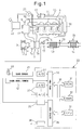
- FIG. 1 is an overall view of a compression ignition type internal combustion engine.
- 1 indicates an engine body, 2 a combustion chamber of each cylinder, 3 an electronically controlled fuel injector for injecting fuel into each combustion chamber 2, 4 an intake manifold, and 5 an exhaust manifold.
- the intake manifold 4 is connected through an intake duct 6 to an outlet of a compressor 7a of an exhaust turbocharger 7, while an inlet of the compressor 7a is connected through an intake air amount detector 8 to an air cleaner 9.
- a throttle valve 10 driven by a step motor is arranged inside the intake duct 6, a throttle valve 10 driven by a step motor is arranged.
- a cooling device 11 is arranged for cooling the intake air which flows through the inside of the intake duct 6.
- the engine cooling water is guided to the inside of the cooling device 11 where the engine cooling water is used to cool the intake air.
- the exhaust manifold 5 is connected to an inlet of an exhaust turbine 7b of the exhaust turbocharger 7.
- An outlet of the exhaust turbine 7b is connected through an exhaust pipe 12 to an inlet of the exhaust purification catalyst 13, while an outlet of the exhaust purification catalyst 13 is connected to a particulate filter 14 for trapping particulate which is contained in the exhaust gas.
- a hydrocarbon feed valve 15 is arranged inside of an exhaust pipe 12 upstream of the exhaust purification catalyst 13, for feeding the diesel oil or other fuel which is used as the fuel of the compression ignition type internal combustion engine. In the embodiment shown in FIG. 1 , diesel oil is used as the hydrocarbons which are fed from the hydrocarbon feed valve 15.
- the present invention can also be applied to a spark ignition type internal combustion engine in which fuel is burned under a lean air-fuel ratio.
- hydrocarbons comprised of gasoline or other fuel used as fuel of a spark ignition type internal combustion engine are fed.
- the exhaust manifold 5 and the intake manifold 4 are connected with each other through an exhaust gas recirculation (hereinafter referred to as an "EGR") passage 16.
- EGR exhaust gas recirculation
- an electronically controlled EGR control valve 17 is arranged inside the EGR passage 16.
- a cooling device 18 is arranged for cooling EGR gas flowing through the inside of the EGR passage 16.
- the engine cooling water is guided to the inside of the cooling device 18 where the engine cooling water is used to cool the EGR gas.
- each fuel injector 3 is connected through a fuel feed tube 19 to a common rail 20.
- This common rail 20 is connected through an electronically controlled variable discharge fuel pump 21 to a fuel tank 22.
- the fuel which is stored inside of the fuel tank 22 is fed by the fuel pump 21 to the inside of the common rail 20.
- the fuel which is fed to the inside of the common rail 20 is fed through each fuel feed tube 19 to the fuel injector 3.
- An electronic control unit 30 is comprised of a digital computer provided with a ROM (read only memory) 32, a RAM (random access memory) 33, a CPU (microprocessor) 34, an input port 35, and an output port 36, which are connected with each other by a bidirectional bus 31.
- ROM read only memory
- RAM random access memory
- CPU microprocessor
- an input port 35 Downstream of the exhaust purification catalyst 13, a temperature sensor 23 for detecting the temperature of the exhaust purification catalyst 13 is attached.
- a differential pressure sensor 24 for detecting a differential pressure before and after the particulate filter 14 is attached.
- the output signals of these temperature sensor 23, differential pressure sensor 24, and intake air amount detector 8 are input through respectively corresponding AD converters 37 to the input port 35.
- an accelerator pedal 40 has a load sensor 41 connected to it which generates an output voltage proportional to the amount of depression L of the accelerator pedal 40.
- the output voltage of the load sensor 41 is input through a corresponding AD converter 37 to the input port 35.
- a crank angle sensor 42 is connected which generates an output pulse every time a crankshaft rotates by, for example, 15°.
- the output port 36 is connected through corresponding drive circuits 38 to each fuel injector 3, step motor for driving the throttle valve 10, hydrocarbon feed valve 15, EGR control valve 17, and fuel pump 21.
- FIG. 2 schematically shows a surface part of a catalyst carrier which is carried on a substrate of the exhaust purification catalyst 13.
- a catalyst carrier 50 made of alumina on which precious metal catalysts 51 and 52 are carried.
- a basic layer 53 is formed which includes at least one element selected from potassium K, sodium Na, cesium Cs, or another such alkali metal, barium Ba, calcium Ca, or another such alkali earth metal, a lanthanoid or another such rare earth and silver Ag, copper Cu, iron Fe, iridium Ir, or another metal able to donate electrons to NO x .
- the exhaust gas flows along the top of the catalyst carrier 50, so the precious metal catalysts 51 and 52 can be said to be carried on the exhaust gas flow surface of the exhaust purification catalyst 13. Further, the surface of the basic layer 53 exhibits basicity, so the surface of the basic layer 53 is called the basic exhaust gas flow surface part 54.
- the precious metal catalyst 51 is comprised of platinum Pt
- the precious metal catalyst 52 is comprised of rhodium Rh. That is, the precious metal catalysts 51 and 52 which are carried on the catalyst carrier 50 are comprised of platinum Pt and rhodium Rh.
- palladium Pd may be further carried or, instead of rhodium Rh, palladium Pd may be carried. That is, the precious metal catalysts 51 and 52 which are carried on the catalyst carrier 50 are comprised of platinum Pt and at least one of rhodium Rh and palladium Pd.
- FIG. 3 schematically shows the reforming action performed at the exhaust purification catalyst 13 at this time.
- the hydrocarbons HC which are injected from the hydrocarbon feed valve 15 become radical hydrocarbons HC with a small carbon number by the catalyst 51.
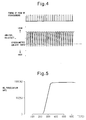
- FIG. 4 shows the feed timing of hydrocarbons from the hydrocarbon feed valve 15 and the change in the air-fuel ratio (A/F)in of the exhaust gas which flows into the exhaust purification catalyst 13.
- the changes in the air-fuel ratio (A/F)in depend on the change in concentration of the hydrocarbons in the exhaust gas which flows into the exhaust purification catalyst 13, so it can be said that the change in the air-fuel ratio (A/F)in shown in FIG. 4 expresses the change in concentration of the hydrocarbons.
- the hydrocarbon concentration becomes higher, the air-fuel ratio (A/F)in becomes smaller, so, in FIG. 4 , the more to the rich side the air-fuel ratio (A/F)in becomes, the higher the hydrocarbon concentration.
- FIG. 5 shows the NO x purification rate by the exhaust purification catalyst 13 with respect to the catalyst temperatures of the exhaust purification catalyst 13 when periodically making the concentration of hydrocarbons flowing into the exhaust purification catalyst 13 change so as to, as shown in FIG. 4 , make the air-fuel ratio (A/F)in of the exhaust gas flowing to the exhaust purification catalyst 13 change.
- the inventors engaged in research relating to NO x purification for a long time. In the process of research, they learned that if making the concentration of hydrocarbons flowing into the exhaust purification catalyst 13 vibrate by within a predetermined range of amplitude and within a predetermined range of period, as shown in FIG. 5 , an extremely high NO x purification rate is obtained even in a 400°C or higher high temperature region.
- FIGS. 6A and 6B schematically show the surface part of the catalyst carrier 50 of the exhaust purification catalyst 13.
- FIGS. 6A and 6B show the reaction which is presumed to occur when the concentration of hydrocarbons flowing into the exhaust purification catalyst 13 is made to vibrate by within a predetermined range of amplitude and within a predetermined range of period.
- FIG. 6A shows when the concentration of hydrocarbons flowing into the exhaust purification catalyst 13 is low
- FIG. 6B shows when hydrocarbons are fed from the hydrocarbon feed valve 15 and the concentration of hydrocarbons flowing into the exhaust purification catalyst 13 becomes higher.
- the air-fuel ratio of the exhaust gas which flows into the exhaust purification catalyst 13 is maintained lean except for an instant, so the exhaust gas which flows into the exhaust purification catalyst 13 normally becomes a state of oxygen excess. Therefore, the NO which is contained in the exhaust gas, as shown in FIG. 6A , is oxidized on the platinum 51 and becomes NO 2 . Next, this NO 2 is further oxidized and becomes NO 3 . Further part of the NO 2 becomes NO 2 - . In this case, the amount of production of NO 3 is far greater than the amount of production of NO 2 - . Therefore, on the platinum Pt 51, a large amount of NO 3 and a small amount of NO 2 - are produced. These NO 3 and NO 2 - are strong in activity. Below, these NO 3 and NO 2 - will be referred to as the active NO x * .
- the hydrocarbons are fed from the hydrocarbon feed valve 15, as shown in FIG. 3 , the hydrocarbons are reformed and become radicalized inside of the exhaust purification catalyst 13. As a result, as shown in FIG. 6B , the hydrogen concentration around the active NO x * becomes higher.
- the active NO x * reacts on the platinum 51 with the radical hydrocarbons HC to thereby form the reducing intermediate. This reducing intermediate is adhered or adsorbed on the surface of the basic layer 53.
- the first produced reducing intermediate is considered to be a nitro compound R-NO 2 . If this nitro compound R-NO 2 is produced, the result becomes a nitrile compound R-CN, but this nitrile compound R-CN can only survive for an instant in this state, so immediately becomes an isocyanate compound R-NCO.
- This isocyanate compound R-NCO when hydralzed, becomes an amino compound R-NH 2 . However, in this case, what is hydrolyzed is considered to be part of the isocyanate compound R-NCO. Therefore, as shown in FIG. 6B , the majority of the reducing intermediate which is held or adsorbed on the surface of the basic layer 53 is believed to be the isocyanate compound R-NCO and amine compound R-NH 2 .
- the concentration of hydrocarbons flowing into the exhaust purification catalyst 13 is lowered and the oxygen concentration is raised so that the active NO x * reacts with the reducing intermediate and the NO x is removed. That is, in order for the exhaust purification catalyst 13 to remove the NO x , the concentration of hydrocarbons flowing into the exhaust purification catalyst 13 has to be periodically changed.
- the active NO x * is absorbed in the basic layer 53 in the form of nitrates without producing a reducing intermediate. To avoid this, it is necessary to make the concentration of hydrocarbons flowing into the exhaust purification catalyst 13 vibrate by within a predetermined range of period.
- precious metal catalysts 51 and 52 are carried on the exhaust gas flow surface of the exhaust purification catalyst 13.
- a basic exhaust gas flow surface part 54 is formed around the precious metal catalysts 51 and 52. No x is reduced by the reducing action of the reducing intermediate R-NCO or R-NH 2 held on the basic exhaust gas flow surface part 54, and the vibration period of the hydrocarbon concentration is made the vibration period required for continuation of the production of the reducing intermediate R-NCO or R-NH 2 .
- the injection interval is made 3 seconds.
- the vibration period of the hydrocarbon concentration that is, the feed period of the hydrocarbons HC
- the reducing intermediate R-NCO or R-NH 2 disappears from the surface of the basic layer 53.
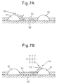
- the active NO x * which is produced on the platinum Pt 53, as shown in FIG. 7A , diffuses in the basic layer 53 in the form of nitrate ions NO 3 - and becomes nitrates. That is, at this time, the NO x in the exhaust gas is absorbed in the form of nitrates inside of the basic layer 53.
- FIG. 7B shows the case where the air-fuel ratio of the exhaust gas which flows into the exhaust purification catalyst 13 is made the stoichiometric air-fuel ratio or rich when the NO x is absorbed in the form of nitrates inside of the basic layer 53.
- the oxygen concentration in the exhaust gas falls, so the reaction proceeds in the opposite direction (NO 3 - ⁇ NO 2 ), and consequently the nitrates absorbed in the basic layer 53 become nitrate ions NO 3 - one by one and, as shown in FIG. 7B , are released from the basic layer 53 in the form of NO 2 .
- the released NO 2 is reduced by the hydrocarbons HC and CO contained in the exhaust gas.
- FIG. 8 schematically shows the case of making the air-fuel ratio (A/F)in of the exhaust gas which flows into the exhaust purification catalyst 13 temporarily rich slightly before the NO x absorption ability of the basic layer 53 becomes saturated.
- the time interval of this rich control is 1 minute or more.
- the NO x which was absorbed in the basic layer 53 when the air-fuel ratio (A/F)in of the exhaust gas was lean is released all at once from the basic layer 53 and reduced when the air-fuel ratio (A/F)in of the exhaust gas is made temporarily rich. Therefore, in this case, the basic layer 53 plays the role of an absorbent for temporarily absorbing NO x .
- the basic layer 53 temporarily adsorbs the NO x . Therefore, if using term of storage as a term including both absorption and adsorption, at this time, the basic layer 53 performs the role of an NO x storage agent for temporarily storing the NO x . That is, in this case, if the ratio of the air and fuel (hydrocarbons) which are supplied into the engine intake passage, combustion chambers 2, and exhaust passage upstream of the exhaust purification catalyst 13 is referred to as the air-fuel ratio of the exhaust gas, the exhaust purification catalyst 13 functions as an NO x storage catalyst which stores the NO x when the air-fuel ratio of the exhaust gas is lean and releases the stored NO x when the oxygen concentration in the exhaust gas falls.
- FIG. 9 shows the NO x purification rate when making the exhaust purification catalyst 13 function as an NO x storage catalyst in this way.
- the abscissa of the FIG. 9 shows the catalyst temperature TC of the exhaust purification catalyst 13.
- the catalyst temperature TC is 300°C to 400°C
- an extremely high NO x purification rate is obtained, but when the catalyst temperature TC becomes a 400°C or higher high temperature, the NO x purification rate falls.
- the NO x purification rate falls because if the catalyst temperature TC becomes 400°C or more, the nitrates break down by heat and are released in the form of NO 2 from the exhaust purification catalyst 13. That is, so long as storing NO x in the form of nitrates, when the catalyst temperature TC is high, it is difficult to obtain a high NO x purification rate.
- the new NO x purification method shown from FIG. 4 to FIGS. 6Aand 6B as will be understood from FIGS. 6A and 6B , nitrates are not formed or even if formed are extremely fine in amount, consequently, as shown in FIG. 5 , even when the catalyst temperature TC is high, a high NO x purification rate is obtained.
- a hydrocarbon feed valve 15 for feeding hydrocarbons is arranged inside of an engine exhaust passage
- an exhaust purification catalyst 13 for reacting NO x contained in exhaust gas and reformed hydrocarbons is arranged in the engine exhaust passage downstream of the hydrocarbon feed valve 15
- precious metal catalysts 51 and 52 are carried on the exhaust gas flow surface of the exhaust purification catalyst 13
- a basic exhaust gas flow surface part 54 is formed around the precious metal catalysts 51 and 52
- the exhaust purification catalyst 13 has the property of reducing the NO x which is contained in exhaust gas if the concentration of hydrocarbons flowing into the exhaust purification catalyst 13 is made to vibrate within a predetermined range of amplitude and within a predetermined range of period and has the property of being increased in storage amount of NO x which is contained in exhaust gas increasing if the vibration period of the hydrocarbon concentration is made longer than this predetermined range, and, at the time of engine operation, the concentration of hydrocarbons flowing into the exhaust purification catalyst 13 is made to vibrate within the predetermined range of amplitude and with the predetermined
- the NO x purification method which is shown from FIG. 4 to FIGS. 6A and 6B can be said to be a new NO x purification method designed to remove NO x without forming almost any nitrates in the case of using an exhaust purification catalyst which carries a precious metal catalyst and forms a basic layer which can absorb NO x .
- this new NO x purification method when using this new NO x purification method, the nitrates which are detected from the basic layer 53 become much smaller in amount compared with the case where making the exhaust purification catalyst 13 function as an NO x storage catalyst.
- this new NO x purification method will be referred to below as the first NO x purification method.
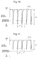
- FIG. 10 shows enlarged the change in the air-fuel ratio (A/F)in shown in FIG. 4 .
- the change in the air-fuel ratio (A/F)in of the exhaust gas flowing into this exhaust purification catalyst 13 simultaneously shows the change in concentration of the hydrocarbons which flow into the exhaust purification catalyst 13.
- ⁇ H shows the amplitude of the change in concentration of hydrocarbons HC which flow into the exhaust purification catalyst 13
- ⁇ T shows the vibration period of the concentration of the hydrocarbons which flow into the exhaust purification catalyst 13.
- (A/F)b shows the base air-fuel ratio which shows the air-fuel ratio of the combustion gas for generating the engine output.
- this base air-fuel ratio (A/F)b shows the air-fuel ratio of the exhaust gas which flows into the exhaust purification catalyst 13 when stopping the feed of hydrocarbons.
- X shows the upper limit of the air-fuel ratio (A/F)in used for producing the reducing intermediate without the produced active NO x * being stored in the form of nitrates inside the basic layer 53 much at all.
- the air-fuel ratio (A/F)in has to be made lower than this upper limit X of the air-fuel ratio.
- X shows the lower limit of the concentration of hydrocarbons required for making the active NO x * and reformed hydrocarbon react to produce a reducing intermediate.
- the concentration of hydrocarbons has to be made higher than this lower limit X.
- whether the reducing intermediate is produced is determined by the ratio of the oxygen concentration and hydrocarbon concentration around the active NO x * , that is, the air-fuel ratio (A/F)in.
- the upper limit X of the air-fuel ratio required for producing the reducing intermediate will below be called the demanded minimum air-fuel ratio.
- the demanded minimum air-fuel ratio X is rich, therefore, in this case, to form the reducing intermediate, the air-fuel ratio (A/F)in is instantaneously made the demanded minimum air-fuel ratio X or less, that is, rich.
- the demanded minimum air-fuel ratio X is lean. In this case, the air-fuel ratio (A/F)in is maintained lean while periodically reducing the air-fuel ratio (A/F)in so as to form the reducing intermediate.
- the exhaust purification catalyst 13 determines whether the demanded minimum air-fuel ratio X becomes rich or becomes lean depending on the oxidizing strength of the exhaust purification catalyst 13.
- the exhaust purification catalyst 13 for example, becomes stronger in oxidizing strength if increasing the carried amount of the precious metal 51 and becomes stronger in oxidizing strength if strengthening the acidity. Therefore, the oxidizing strength of the exhaust purification catalyst 13 changes due to the carried amount of the precious metal 51 or the strength of the acidity.
- the demanded minimum air-fuel ratio X has to be reduced the stronger the oxidizing strength of the exhaust purification catalyst 13. In this way the demanded minimum air-fuel ratio X becomes lean or rich due to the oxidizing strength of the exhaust purification catalyst 13.
- the amplitude of the change in concentration of hydrocarbons flowing into the exhaust purification catalyst 13 and the vibration period of the concentration of hydrocarbons flowing into the exhaust purification catalyst 13 will be explained.
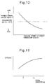
- FIG. 13 shows the relationship between the oxygen concentration in the exhaust gas before the hydrocarbons are fed and the amplitude ⁇ H of the hydrocarbon concentration when the same NO x purification rate is obtained.
- the base air-fuel ratio (A/F)b becomes the lowest at the time of an acceleration operation. At this time, if the amplitude ⁇ H of the hydrocarbon concentration is about 200 ppm, it is possible to remove the NO x well.
- the base air-fuel ratio (A/F)b is normally larger than the time of acceleration operation. Therefore, as shown in FIG. 14 , if the amplitude ⁇ H of the hydrocarbon concentration is 200 ppm or more, an excellent NO x purification rate can be obtained.
- the predetermined range of the amplitude of the hydrocarbon concentration is made 200 ppm to 10000 ppm.
- the vibration period ⁇ T of the hydrocarbon concentration becomes longer, the oxygen concentration around the active NO x * becomes higher in the time after the hydrocarbons are fed to when the hydrocarbons are next fed.
- the vibration period ⁇ T of the hydrocarbon concentration becomes longer than about 5 seconds, the majority of the active NO x * starts to be absorbed in the form of nitrates inside the basic layer 53. Therefore, as shown in FIG. 15 , if the vibration period ⁇ T of the hydrocarbon concentration becomes longer than about 5 seconds, the NO x purification rate falls. Therefore, the vibration period ⁇ T of the hydrocarbon concentration has to be made 5 seconds or less.
- the vibration period of the hydrocarbon concentration is made from 0.3 second to 5 seconds.
- an NO x purification method in the case when making the exhaust purification catalyst 13 function as an NO x storage catalyst will be explained in detail.
- the NO x purification method in the case when making the exhaust purification catalyst 13 function as an NO x storage catalyst in this way will be referred to below as the second NO x purification method.
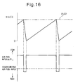
- this second NO x purification method as schematically shown in FIG. 16 , when the stored NO x amount ⁇ NOX of NO x which is stored in the basic layer 53 exceeds a predetermined allowable amount MAX, the air-fuel ratio (A/F)in of the exhaust gas flowing into the exhaust purification catalyst 13 is temporarily made rich. If the air-fuel ratio (A/F)in of the exhaust gas is made rich, the NO x which was stored in the basic layer 53 when the air-fuel ratio (A/F)in of the exhaust gas was lean is released from the basic layer 53 all at once and reduced. Due to this, the NO x is removed.
- the stored NO x amount ⁇ NOX is, for example, calculated from the amount of NO x which is exhausted from the engine.
- the exhausted NO x amount NOXA of NO x which is exhausted from the engine per unit time is stored as a function of the injection amount Q and engine speed N in the form of a map such as shown in FIG. 17 in advance in the ROM 32.
- the stored NO x amount ⁇ NOX is calculated from exhausted NO x amount NOXA.
- the period during which the air-fuel ratio (A/F)in of the exhaust gas is made rich is usually 1 minute or more.
- the fuel injector 3 injects additional fuel WR into the combustion chamber 2 in addition to the combustion-use fuel Q so that the air-fuel ratio (A/F)in of the exhaust gas flowing into the exhaust purification catalyst 13 is made rich.
- the abscissa indicates the crank angle.
- This additional fuel WR is injected at a timing at which it will burn, but will not appear as engine output, that is, slightly before ATDC90° after compression top dead center.
- This fuel amount WR is stored as a function of the injection amount Q and engine speed N in the form of a map such as shown in FIG. 19 in advance in the ROM 32.
- the amplitude ⁇ H and vibration period ⁇ T of the hydrocarbon concentration have to be suitably controlled. That is, to use the first NO x purification method to remove the NO x well, the air-fuel ratio (A/F)in of the exhaust gas which flows into the exhaust purification catalyst 13 has to be made the demanded minimum air-fuel ratio X or less by control of the amplitude ⁇ H of the hydrocarbon concentration and the vibration period ⁇ T of the hydrocarbon concentration has to be controlled to 0.3 second to 5 seconds.
- the vibration period ⁇ T of the hydrocarbon concentration is controlled by controlling the injection amount of hydrocarbons from the hydrocarbon feed valve 15 and the vibration period ⁇ T of the hydrocarbon concentration is controlled by controlling the injection period of hydrocarbons from the hydrocarbon feed valve 15.
- the injection amount of hydrocarbons from the hydrocarbon feed valve 15 is controlled by controlling at least one of the injection time or injection pressure of hydrocarbons from the hydrocarbon feed valve 15.
- FIG. 20 shows the three injection patterns A, B, and C of hydrocarbons which are injected by different injection times from the hydrocarbon feed valve 15 under the same injection pressure.
- the injection time is the shortest in the injection pattern A and is longest in the injection pattern C.
- FIG. 20 shows the hydrogen concentration in the exhaust gas which flows into the exhaust purification catalyst 13 after injection by the injection patterns A, B, and C.
- FIG. 20 shows the NO x purification rate and amount of hydrocarbons passing straight through the exhaust purification catalyst 13 at the time of injection by the injection patterns A, B, and C.
- FIG. 20 in the region RB above the complete oxidation limit XA, a partial oxidation action of hydrocarbons is performed in the exhaust purification catalyst 13.
- the hatching region RB expresses the amount of partially oxidized hydrocarbons.
- the reducing intermediate is produced from the partially oxidized hydrocarbons, so the NO x purification action is performed by the first NO x purification method by the partially oxidized hydrocarbon. Note that, in actuality, part of the partially oxidized hydrocarbons ends up being oxidized without being used for production of the reducing intermediate, while the remaining partially oxidized hydrocarbons are used to form the reducing intermediate.
- the injection pattern A shows the case where, in this way, the amount of partially oxidized hydrocarbons RB is insufficient. In this case, as shown in FIG. 20 , the NO x purification rate will fall.
- the injection pattern B shows the case where the injection time is made longer than in the injection pattern A so as to increase the amount of partially oxidized hydrocarbons RB. If the injection time is made longer, the amount of partially oxidized hydrocarbons RB is increased, so, as shown in FIG. 20 , the NO x purification rate becomes higher. Note that, FIG. 20 shows the case where even with the injection pattern B, the amount of partially oxidized hydrocarbons RB is somewhat insufficient.
- the injection pattern C shows the case where to further increase the amount of partially oxidized hydrocarbons RB, the injection time is made longer compared with the injection pattern B.
- the NO x purification rate is improved.
- the hydrocarbon concentration exceeds the pass through limit XB, so the hydrocarbons pass straight through.
- the injection pattern B by which the peak of the hydrocarbon concentration becomes the pass through limit XB is used.
- the injection pattern A is used when a sufficiently high NO x purification rate is obtained even if the peak of the hydrocarbon concentration does not reach the pass through limit XB. That is, in the present invention, then performing the NO x purification action by the first NO x purification method, normally the injection pattern A or the injection pattern B is used.
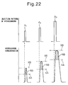
- FIG. 21 and FIG. 22 show one example when considering this for control of injection of hydrocarbons.
- the example shown in FIG. 21 shows the case where the injection pressure is maintained constant and the injection time is controlled in that state so as to control the injection amount of hydrocarbons
- the example shown in FIG. 22 shows the case where both the injection pressure and injection time are controlled so as to control the injection amount of hydrocarbons.
- a 1 shows the injection pattern when the engine speed and load are relatively low
- a 3 shows the injection pattern when the engine speed and load are relatively high
- a 2 shows the injection pattern when the engine speed and load are respectively between the case shown by A 1 and the case shown by A 3 . That is, as the engine speed and load become higher, the injection pattern is made to change from A 1 toward A 3 .
- the higher the engine speed and load the higher the temperature of the exhaust purification catalyst 13 becomes. Therefore, the higher the engine speed and load, the higher the complete oxidation limit XA and pass through limit XB as well.
- the higher the speed and load the greater the NO x exhausted from the engine per unit time. Therefore, the higher the engine speed and load, the greater the amount RB of partially oxidized hydrocarbons has to be made.
- the injection amount of hydrocarbons has to be increased. Therefore, to enable the production of the amount of partially oxidized hydrocarbons required for removal of NO x , in the example shown in FIG.
- the higher the engine speed and load the longer the injection time is made so as to make the injection amount increase, while in the example shown in FIG. 22 , the higher the engine speed and load, the longer both the injection pressure and injection time are made so as to make the injection amount increase.
- the injection amount can be controlled by controlling just the injection time or by controlling both the injection pressure and injection time, but below the case of controlling just the injection time so as to control the injection amount will be used as an example to explain the present invention.
- FIG. 23A shows the equivalent injection time line enabling the production of the amount of partially oxidized hydrocarbons required for removal of NO x when controlling just the injection time to control the injection amount in this way.
- the injection time of hydrocarbons becomes longer the greater fuel injection amount Q to the inside of the combustion chamber 2, that is, the greater the engine load, and the higher the engine speed N.
- This injection time WT is stored as a function of the fuel injection amount Q and engine speed N in the form of a map as shown in FIG. 23B in advance in the ROM 32.
- the optimum vibration amplitude ⁇ T of the hydrocarbon concentration that is, the injection period ⁇ T of the hydrocarbons, is similarly stored as a function of the injection amount Q and engine speed N in the form of a map as shown in FIG. 23C in advance in the ROM 32.
- FIG. 24 shows the injection pattern of hydrocarbons and the change in the hydrocarbon concentration at the time when a good NO x purification action by the first NO x purification method is performed in this way.
- the amount of hydrocarbons shown in the region RA in FIG. 24 is made to completely oxidize.
- the exhaust purification catalyst 13 is maintained in the activated state.
- This stored NO x can be educed using the second NO x purification method.
- the inventors engaged in repeated research and as a result found that this stored NO x can be reduced even if using a third NO x purification method separate from the second NO x purification method.
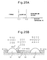
- FIGS. 25A, 25B , and 26 the NO x purification action by this third NO x purification method will be explained.
- FIG. 25A shows the behavior of the NO x which is stored in the exhaust purification catalyst 13.
- TC1 and TC2 indicate the temperatures of the exhaust purification catalyst 13.
- the NO x which is stored in the exhaust purification catalyst 13 is held in the state stored in the exhaust purification catalyst 13 when the temperature TC of the exhaust purification catalyst 13 is lower than TC1.
- TC1 shows the NO x release temperature at which the stored NO x is released.
- this active NO x * reacts with the radicalized hydrocarbons HC on the platinum 51 whereby a reducing intermediate is produced.
- this reducing intermediate as shown in FIG. 6A , reacts with the active NO x * to be removed.
- the NO x purification method which produces a reducing intermediate from the stored NO x in this way and uses this to remove the NO x is the above third NO x purification method.
- the injection amount of hydrocarbons from the hydrocarbon feed valve 15 is controlled so that the amplitude of the change of concentration of hydrocarbons flowing into the exhaust purification catalyst 13 becomes within a predetermined range of amplitude
- the injection period of hydrocarbons from the hydrocarbon feed valve 15 is controlled so that the concentration of hydrocarbons flowing into the exhaust purification catalyst 13 vibrates by a predetermined range of period, and thereby the NO x which is contained in the exhaust gas and the NO x which is stored in the exhaust purification catalyst 13 are reduced.
- the NO x contained in the exhaust gas and the NO x stored in the exhaust purification catalyst 13 react with the reformed hydrocarbons whereby a reducing intermediate which contains nitrogen and hydrocarbons is produced.
- the injection period of the hydrocarbons from the hydrocarbon feed valve 15 is made the period which is required for continued production of the reducing intermediate. In the present invention, the injection period of the hydrocarbons is from 0.3 second to 5 seconds.
- TC2 shows the boundary temperature at which the released stored NO x is either held in the adsorbed state or the nitrates are broken down and NO x is released.
- TC2 shows the boundary temperature at which the released stored NO x is either held in the adsorbed state or the nitrates are broken down and NO x is released.
- no NO x purification action by the third NO x purification method is performed. Therefore, the NO x purification action can be performed by third NO x purification method when the temperature TC of the exhaust purification catalyst 13 is between the NO x release temperature TC1 and the boundary temperature TC2.
- the NO x release temperature TC1 and boundary temperature TC2 are functions of the NO x stored amount ⁇ NOX stored in the exhaust purification catalyst 13. As shown in FIG. 26 , these NO x release temperature TC1 and boundary temperature TC2 gradually become lower as the NO x stored amount ⁇ NOX increases. That is, it is learned that the range of the temperature of the exhaust purification catalyst 13 where an NO x purification action can be performed by the third NO x purification method becomes lower the greater the NO x stored amount ⁇ NOX. This range of the temperature of the exhaust purification catalyst 13 where an NO x purification action can be performed by the third NO x purification method is found in advance by experiments.
- the heat of the oxidation reaction of the fed hydrocarbons causes the temperature of the exhaust purification catalyst 13 to rise.
- the temperature of the exhaust purification catalyst 13 rises to between the NO x release temperature TC1 and the boundary temperature TC2 and there are hydrocarbons in the surroundings at this time, the NO x which is released from the exhaust purification catalyst 13 can be removed by the NO x purification action by the third NO x purification method.
- FIG. 27 shows the injection patterns of hydrocarbons and a change in hydrogen concentration when performing an NO x purification action by the third NO x purification method.
- WTK as shown by WTK, it is learned that the injection time when performing an NO x purification action by the third NO x purification method is made longer compared with the injection time TW ( FIG. 24 ) when performing an NO x purification action by the first NO x purification method, and thereby the injection amount is increased. If the injection amount is increased in this way, in addition to the NO x which is contained in the exhaust gas, the NO x which was stored in the exhaust purification catalyst 13 is reduced. Therefore, a good NO x purification action is performed by the third NO x purification method.
- the injection amount is increased, the amount RA of hydrocarbons which is completely oxidized at the exhaust purification catalyst 13 is increased, so the heat of oxidation reaction is increased and, as a result, the temperature of the exhaust purification catalyst 13 rises.
- the exhaust purification catalyst 13 itself does not particularly have to be raised in temperature.
- the temperature of the exhaust purification catalyst 13 need only be maintained at the temperature at that time. In this case, to maintain the temperature of the exhaust purification catalyst 13 as it is, it is necessary to maintain the amount of hydrocarbons which is completely oxidized per unit time constant.
- the amount of hydrocarbons which is completely oxidized per unit time can be expressed by the value (RA/ ⁇ TK) of the amount RA of hydrocarbons completely oxidized per injection divided by the injection period ⁇ TK.
- the amount RA of hydrocarbons completely oxidized per injection is proportional to the injection amount, while the injection amount is proportional to the injection time WTK, so the amount of hydrocarbons completely oxidized per unit time can be expressed by the value (WTK/ ⁇ TK) of the injection time WTK divided by the injection period ⁇ TK. Therefore, to maintain the temperature of the exhaust purification catalyst 13 as it is, it is sufficient to make this value (WTK/ ⁇ TK) equal to the (WT/ ⁇ T) of the case shown in FIG. 24 .
- the boundary temperature TC2 is low.
- the temperature of the exhaust purification catalyst 13 will often end up exceeding the boundary temperature TC2. Therefore, when in actuality the NO x purification action is started by the first NO x purification method, the NO x purification action can be performed by the third NO x purification method only when the NO x stored amount ⁇ NOX is small.
- the NO x purification action is started by the first NO x purification method and the temperature of the exhaust purification catalyst 13 exceeds the boundary temperature TC2, as explained above, the nitrates which are stored in the exhaust purification catalyst 13 are broken down and NO x is released from the exhaust purification catalyst 13. If NO x is released from the exhaust purification catalyst 13 in this way, this NO x ends up being exhausted into the outside air without being reduced. Therefore, to reduce the NO x which is released at this time, the air-fuel ratio of the exhaust gas which flows into the exhaust purification catalyst 13 is temporarily made rich. That is, at this time, the NO x purification action by the second NO x purification method is used for removal of NO x .
- the first NO x purification method which makes the concentration of hydrocarbons which flow into the exhaust purification catalyst 13 vibrate by within a predetermined range of amplitude and within a predetermined range of period so as to reduce the NO x which is contained in the exhaust gas
- the second NO x purification method which makes the concentration of hydrocarbons which flow into the exhaust purification catalyst 13 larger than within the predetermined range of amplitude to thereby make the exhaust purification catalyst 13 release the stored NO x
- the third NO x purification method which makes the concentration of hydrocarbons which flow into the exhaust purification catalyst 13 vibrate by within a predetermined range of amplitude and within a predetermined range of period so as to reduce the NO x contained in the exhaust gas and the NO x stored in the exhaust purification catalyst 13 together are selectively used in accordance with the operating state of the engine.
- the NO x purification action by the third NO x purification method can be performed when the temperature of the exhaust purification catalyst 13 is within the predetermined temperature range.
- This temperature range decreases as the NO x stored amount which is stored in the exhaust purification catalyst 13 increases.
- the NO x purification action by the third NO x purification method is performed when the NO x stored amount which is stored in the exhaust purification catalyst 13 is lower than a predetermined set value.
- FIG. 29 shows the differences in changes of the air-fuel ratio of the exhaust gas which flows into the exhaust purification catalyst 13 under the same engine operating conditions when the NO x purification action is performed by the first NO x purification method, the NO x purification action is performed by the second NO x purification method, and the NO x purification action is performed by the third NO x purification method.
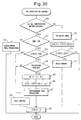
- FIG. 30 shows the NO x purification control routine. This routine is executed by interruption every predetermined time interval.
- step 60 it is judged if the NO x purification action by the first NO x purification method is possible. For example, when it is judged from the output signal of the temperature sensor 23 that the temperature TC of the exhaust purification catalyst 13 exceeds the activation temperature, it is judged that the NO x purification action by the first NO x purification method is possible.
- the routine proceeds to step 61 where it is judged if the NO x purification processing by the second NO x purification method has been switched to the NO x purification processing by the first NO x purification method now.
- step 62 processing is performed for feeding hydrocarbons by the injection time WTij which is calculated from FIG. 23B and the injection period ⁇ Tij which is calculated from FIG. 23C .
- the NO x purification action by the first NO x purification method is performed.
- step 70 the NO x amount NOXA which is exhausted per unit time is calculated from the map shown in FIG. 17 .
- ⁇ NOX is increased by the exhausted NO x amount NOXA whereby the stored NO x amount ⁇ NOX is calculated.
- step 72 it is judged if the stored NO x amount ⁇ NOX exceeds the allowable value MAX.
- the routine proceeds to step 73 where the additional fuel amount WR is calculated from the map shown in FIG. 19 and an additional fuel injection action is performed.
- step 68 ⁇ NOX is cleared.
- step 61 when it is judged at step 61 that the NO x purification processing by the second NO x purification method is switched to the NO x purification processing by the first NO x purification method now, the routine proceeds to step 63 where it is judged if the NO x stored amount ⁇ NOX is smaller than a predetermined set value MD.
- step 64 it is judged if the NO x purification processing by the third NO x purification method is possible, that is, if the temperature TC of the exhaust purification catalyst 13 is between the NO x release temperature TC1 and the boundary temperature TC2.
- step 65 the NO x purification processing is performed by the third NO x purification method. Note that it is possible to omit either of step 63 or step 64.
- the injection time WT which is calculated from the map which is shown in FIG. 23B in accordance with the operating conditions is multiplied with a predetermined constant C whereby the injection time WTK is calculated.
- the following formula is used as the basis to calculate the injection period ⁇ TK of hydrocarbons at the time of NO x purification processing by the third NO x purification method. ⁇ TK ⁇ WTK / WT • ⁇ T
- step 67 processing is performed for feeding hydrocarbons by the injection time WTK which was calculated at step 65 and the injection period ⁇ TK which was calculated at step 66. At this time, the NO x purification action by the third NO x purification method is performed. Next, the routine proceeds to step 68.
- step 63 when it is judged at step 63 that the NO x stored amount ⁇ NOX is greater than the predetermined set value MD or when it is judged at step 64 that NO x purification processing by the third NO x purification method is not possible, the routine proceeds to step 69 where the air-fuel ratio of the exhaust gas which flows into the exhaust purification catalyst 13 is temporarily made rich. That is, at this time, the NO x is removed using the NO x purification action by the second NO x purification method. Next, the routine proceeds to step 68.
- an oxidation catalyst for reforming the hydrocarbons in the engine exhaust passage upstream of the exhaust purification catalyst 13, an oxidation catalyst for reforming the hydrocarbons can be arranged.
Landscapes
- Engineering & Computer Science (AREA)
- Chemical & Material Sciences (AREA)
- Combustion & Propulsion (AREA)
- Mechanical Engineering (AREA)
- General Engineering & Computer Science (AREA)
- Chemical Kinetics & Catalysis (AREA)
- Health & Medical Sciences (AREA)
- Biomedical Technology (AREA)
- Environmental & Geological Engineering (AREA)
- Analytical Chemistry (AREA)
- General Chemical & Material Sciences (AREA)
- Oil, Petroleum & Natural Gas (AREA)
- Toxicology (AREA)
- Exhaust Gas After Treatment (AREA)
- Exhaust Gas Treatment By Means Of Catalyst (AREA)
Claims (10)
- Procédé de purification de NOx d'un système de purification d'échappement d'un moteur à combustion interne dans lequel
une vanne d'alimentation en hydrocarbures (15) pour introduire des hydrocarbures est disposée à l'intérieur d'un passage d'échappement de moteur,
un catalyseur de purification d'échappement (13) pour faire réagir NOx contenu dans des gaz d'échappement et des hydrocarbures réformés est disposé à l'intérieur du passage d'échappement de moteur en aval de la vanne d'alimentation en hydrocarbures (15),
un catalyseur de métal précieux (51, 52) est supporté sur une surface d'écoulement de gaz d'échappement du catalyseur de purification d'échappement (13) et une partie de surface d'écoulement de gaz d'échappement basique (54) est formée autour du catalyseur de métal précieux (51, 52),
le catalyseur de purification d'échappement (13) présente une propriété de réduction du NOx qui est contenu dans des gaz d'échappement si une concentration en hydrocarbures s'écoulant dans le catalyseur de purification d'échappement (13) est amenée à osciller dans un intervalle prédéterminé d'amplitude et dans un intervalle prédéterminé de période et présente une propriété d'être augmentée en quantité de stockage de NOx qui est contenu dans des gaz d'échappement si la période d'oscillation de la concentration en hydrocarbures est rendue plus longue que ledit intervalle prédéterminé, au moment du fonctionnement du moteur, lorsque NOx est stocké dans le catalyseur de purification d'échappement (13), une quantité d'injection d'hydrocarbures à partir de la vanne d'alimentation en hydrocarbures (15) est contrôlée de sorte que l'amplitude de la modification de concentration en hydrocarbures s'écoulant dans le catalyseur de purification d'échappement (13) se trouve dans l'intervalle prédéterminé d'amplitude, et une période d'injection d'hydrocarbures à partir de la vanne d'alimentation en hydrocarbures (15) est contrôlée de sorte que la concentration en hydrocarbures s'écoulant dans le catalyseur de purification d'échappement (13) oscille dans l'intervalle prédéterminé de période, pour réduire par-là le NOx qui est contenu dans les gaz d'échappement et le NOx qui est stocké dans le catalyseur de purification d'échappement (13). - Procédé de purification de NOx d'un système de purification d'échappement d'un moteur à combustion interne selon la revendication 1, dans lequel, à l'intérieur dudit catalyseur de purification d'échappement (13), le NOx contenu dans les gaz d'échappement et le NOx stocké dans le catalyseur de purification d'échappement (13) réagissent avec les hydrocarbures réformés, sur quoi un intermédiaire réducteur qui contient de l'azote et des hydrocarbures est produit et dans lequel la période d'injection des hydrocarbures est la période qui est exigée pour une production continue de l'intermédiaire réducteur.
- Procédé de purification de NOx d'un système de purification d'échappement d'un moteur à combustion interne selon la revendication 2, dans lequel ladite période d'injection d'hydrocarbures est 0,3 seconde à 5 secondes.
- Procédé de purification de NOx d'un système de purification d'échappement d'un moteur à combustion interne selon la revendication 1, dans lequel, au moment du fonctionnement du moteur, un premier procédé de purification de NOx qui fait que la concentration en hydrocarbures qui s'écoulent dans le catalyseur de purification d'échappement (13) oscille dans l'intervalle prédéterminé d'amplitude et dans l'intervalle prédéterminé de période afin de réduire le NOx contenu dans les gaz d'échappement, un second procédé de purification de NOx qui fait que la concentration en hydrocarbures qui s'écoulent dans le catalyseur de purification d'échappement (13) est supérieure à celle dans ledit intervalle prédéterminé d'amplitude pour faire par-là en sorte que le catalyseur de purification d'échappement (13) libère et réduise le NOx stocké, et un troisième procédé de purification de NOx qui fait que la concentration en hydrocarbures qui s'écoulent dans le catalyseur de purification d'échappement (13) oscille dans l'intervalle prédéterminé d'amplitude et dans l'intervalle prédéterminé de période afin de réduire le NOx contenu dans les gaz d'échappement et le NOx stocké dans le catalyseur de purification d'échappement (13) ensemble sont sélectivement utilisés selon un état de fonctionnement du moteur.
- Procédé de purification de NOx d'un système de purification d'échappement d'un moteur à combustion interne selon la revendication 4, dans lequel, si NOx est stocké dans le catalyseur de purification d'échappement (13) lorsque le catalyseur de purification d'échappement est activé et l'action de purification de NOx par le premier procédé de purification de NOx est démarrée, soit l'action de purification de NOx par le second procédé de purification de NOx soit l'action de purification de NOx par le troisième procédé de purification de NOx est réalisée.
- Procédé de purification de NOx d'un système de purification d'échappement d'un moteur à combustion interne selon la revendication 4, dans lequel l'action de purification de NOx par le troisième procédé de purification de NOx peut être réalisée lorsqu'une température du catalyseur de purification d'échappement (13) se trouve dans un intervalle de température prédéterminé et dans lequel ledit intervalle de température diminue lorsqu'une quantité stockée de NOx qui est stockée dans le catalyseur de purification d'échappement (13) augmente.
- Procédé de purification de NOx d'un système de purification d'échappement d'un moteur à combustion interne selon la revendication 4, dans lequel l'action de purification de NOx par le troisième procédé de purification de NOx est réalisée lorsqu'une quantité stockée de NOx qui est stockée dans le catalyseur de purification d'échappement (13) est inférieure à une valeur fixée prédéterminée.
- Procédé de purification de NOx d'un système de purification d'échappement d'un moteur à combustion interne selon la revendication 4, dans lequel lorsque l'action de purification de NOx par le troisième procédé de purification de NOx est réalisée, l'amplitude de la modification de concentration en hydrocarbures s'écoulant dans le catalyseur de purification d'échappement (13) est augmentée en comparaison avec lorsque l'action de purification de NOx par le premier procédé de purification de NOx est réalisée.
- Procédé de purification de NOx d'un système de purification d'échappement d'un moteur à combustion interne selon la revendication 1, dans lequel ledit catalyseur de métal précieux (51, 52) est constitué de platine Pt et d'au moins un de rhodium Rh et de palladium Pd.
- Procédé de purification de NOx d'un système de purification d'échappement d'un moteur à combustion interne selon la revendication 1, dans lequel une couche basique (53) contenant un métal alcalin, un métal alcalino-terreux, une terre rare, ou un métal qui peut donner des électrons à NOx est formée sur la surface d'écoulement de gaz d'échappement du catalyseur de purification d'échappement (13) et dans lequel une surface de ladite couche basique (53) forme ladite partie de surface d'écoulement de gaz d'échappement basique (54).
Applications Claiming Priority (1)
| Application Number | Priority Date | Filing Date | Title |
|---|---|---|---|
| PCT/JP2011/059880 WO2012140784A1 (fr) | 2011-04-15 | 2011-04-15 | Épurateur de gaz d'échappement destiné à un moteur à combustion interne |
Publications (4)
| Publication Number | Publication Date |
|---|---|
| EP2532852A1 EP2532852A1 (fr) | 2012-12-12 |
| EP2532852A8 EP2532852A8 (fr) | 2013-02-27 |
| EP2532852A4 EP2532852A4 (fr) | 2014-11-05 |
| EP2532852B1 true EP2532852B1 (fr) | 2016-08-24 |
Family
ID=47008986
Family Applications (1)
| Application Number | Title | Priority Date | Filing Date |
|---|---|---|---|
| EP11801951.2A Not-in-force EP2532852B1 (fr) | 2011-04-15 | 2011-04-15 | Procédé de purification d'échappement pour moteur à combustion interne |
Country Status (5)
| Country | Link |
|---|---|
| US (1) | US9021788B2 (fr) |
| EP (1) | EP2532852B1 (fr) |
| JP (1) | JP5218672B2 (fr) |
| CN (1) | CN102834595B (fr) |
| WO (1) | WO2012140784A1 (fr) |
Families Citing this family (13)
| Publication number | Priority date | Publication date | Assignee | Title |
|---|---|---|---|---|
| WO2014122728A1 (fr) * | 2013-02-05 | 2014-08-14 | トヨタ自動車株式会社 | Épurateur de gaz d'échappement pour moteur à combustion interne |
| EP2772302A1 (fr) | 2013-02-27 | 2014-09-03 | Umicore AG & Co. KG | Catalyseur d'oxydation hexagonale |
| WO2014167652A1 (fr) * | 2013-04-09 | 2014-10-16 | トヨタ自動車株式会社 | Dispositif d'épuration des gaz d'échappement de moteur à combustion interne |
| DE102013207709A1 (de) | 2013-04-26 | 2014-10-30 | Umicore Ag & Co. Kg | Entschwefelung von NOX-Speicherkatalysatoren |
| US9856809B2 (en) * | 2013-04-30 | 2018-01-02 | Toyota Jidosha Kabushiki Kaisha | Exhaust purification device for internal combustion engine |
| JP5741643B2 (ja) * | 2013-08-08 | 2015-07-01 | トヨタ自動車株式会社 | 内燃機関の排気浄化装置 |
| DE102013218234B4 (de) | 2013-09-11 | 2015-05-28 | Umicore Ag & Co. Kg | Verwendung unterschiedlicher Strategien bei der Regeneration von Stickoxidspeicherkatalysatoren zur Verminderung der N2O-Bildung |
| DE102015204034A1 (de) | 2015-03-06 | 2016-09-08 | Robert Bosch Gmbh | Verfahren zur Steuerung und/oder Regelung der Einspritzmenge an Reduktionsmittel |
| JP6547348B2 (ja) * | 2015-03-18 | 2019-07-24 | いすゞ自動車株式会社 | 排気浄化システム |
| JP6358191B2 (ja) | 2015-08-17 | 2018-07-18 | トヨタ自動車株式会社 | 内燃機関の制御装置 |
| JP2017194022A (ja) * | 2016-04-21 | 2017-10-26 | トヨタ自動車株式会社 | 排気浄化装置の制御装置 |
| US10914214B2 (en) | 2016-09-20 | 2021-02-09 | Umicore Ag & Co. Kg | SCR diesel particle filter with oxidation catalyst and oxygen storage catalyst loadings, and exhaust system including the same |
| US10781735B2 (en) | 2018-05-18 | 2020-09-22 | Umicore Ag & Co Kg | Exhaust emission reduction system having an HC-trap and NOx-trap combination designed for operating under strategic lean conditions |
Family Cites Families (132)
| Publication number | Priority date | Publication date | Assignee | Title |
|---|---|---|---|---|
| US5075274A (en) | 1989-03-15 | 1991-12-24 | Kabushiki Kaisha Riken | Exhaust gas cleaner |
| US5052178A (en) | 1989-08-08 | 1991-10-01 | Cummins Engine Company, Inc. | Unitary hybrid exhaust system and method for reducing particulate emmissions from internal combustion engines |
| US5057483A (en) | 1990-02-22 | 1991-10-15 | Engelhard Corporation | Catalyst composition containing segregated platinum and rhodium components |
| JP2605586B2 (ja) | 1992-07-24 | 1997-04-30 | トヨタ自動車株式会社 | 内燃機関の排気浄化装置 |
| US6667018B2 (en) | 1994-07-05 | 2003-12-23 | Ngk Insulators, Ltd. | Catalyst-adsorbent for purification of exhaust gases and method for purification of exhaust gases |
| EP0710499A3 (fr) | 1994-11-04 | 1997-05-21 | Agency Ind Science Techn | Nettoyeur de gaz d'échappement et méthode pour nettoyer un gaz d'échappement |
| JP3456408B2 (ja) | 1997-05-12 | 2003-10-14 | トヨタ自動車株式会社 | 内燃機関の排気浄化装置 |
| EP0982487B1 (fr) | 1997-05-12 | 2003-07-16 | Toyota Jidosha Kabushiki Kaisha | Appareil de reduction des emissions de gaz d'echappement pour moteur a combustion interne |
| GB9713428D0 (en) | 1997-06-26 | 1997-08-27 | Johnson Matthey Plc | Improvements in emissions control |
| FR2778205B1 (fr) | 1998-04-29 | 2000-06-23 | Inst Francais Du Petrole | Procede d'injection controlee d'hydrocarbures dans une ligne d'echappement d'un moteur a combustion interne |
| US7707821B1 (en) | 1998-08-24 | 2010-05-04 | Legare Joseph E | Control methods for improved catalytic converter efficiency and diagnosis |
| US6718756B1 (en) | 1999-01-21 | 2004-04-13 | Mitsubishi Jidosha Kogyo Kabushiki Kaisha | Exhaust gas purifier for use in internal combustion engine |
| JP2000257419A (ja) | 1999-03-03 | 2000-09-19 | Toyota Motor Corp | 排気浄化方法及び装置 |
| US6685897B1 (en) | 2000-01-06 | 2004-02-03 | The Regents Of The University Of California | Highly-basic large-pore zeolite catalysts for NOx reduction at low temperatures |
| US6311484B1 (en) | 2000-02-22 | 2001-11-06 | Engelhard Corporation | System for reducing NOx transient emission |
| DE10023439A1 (de) | 2000-05-12 | 2001-11-22 | Dmc2 Degussa Metals Catalysts | Verfahren zur Entfernung von Stickoxiden und Rußpartikeln aus dem mageren Abgas eines Verbrennungsmotors und Abgasreinigungssystem hierfür |
| MXPA03007403A (es) | 2001-02-19 | 2004-07-30 | Toyota Motor Co Ltd | Catalizador para purificar gases de escape. |
| JP2002364415A (ja) | 2001-06-07 | 2002-12-18 | Mazda Motor Corp | エンジンの排気浄化装置 |
| LU90795B1 (en) | 2001-06-27 | 2002-12-30 | Delphi Tech Inc | Nox release index |
| US6677272B2 (en) | 2001-08-15 | 2004-01-13 | Corning Incorporated | Material for NOx trap support |
| US7082753B2 (en) * | 2001-12-03 | 2006-08-01 | Catalytica Energy Systems, Inc. | System and methods for improved emission control of internal combustion engines using pulsed fuel flow |
| KR20050044672A (ko) | 2001-12-03 | 2005-05-12 | 캐탈리티카 에너지 시스템즈 인코포레이티드 | 내연 기관의 향상된 배출물 제어를 위한 시스템 및 방법 |
| US20030113242A1 (en) | 2001-12-18 | 2003-06-19 | Hepburn Jeffrey Scott | Emission control device for an engine |
| EP1477643B1 (fr) | 2002-02-19 | 2014-01-22 | Yasuo Ajisaka | Filtre de purification des gaz d'echappement des diesels |
| JP3963130B2 (ja) | 2002-06-27 | 2007-08-22 | トヨタ自動車株式会社 | 触媒劣化判定装置 |
| DE60230977D1 (de) | 2002-07-31 | 2009-03-12 | Umicore Ag & Co Kg | Verfahren zur Regenerierung eines Stickoxid-Speicherkatalysators |
| JP2004068700A (ja) | 2002-08-06 | 2004-03-04 | Toyota Motor Corp | 排気ガス浄化方法 |
| US7332135B2 (en) * | 2002-10-22 | 2008-02-19 | Ford Global Technologies, Llc | Catalyst system for the reduction of NOx and NH3 emissions |
| WO2004046514A1 (fr) | 2002-11-15 | 2004-06-03 | Catalytica Energy Systems, Inc. | Dispositifs et procedes pour reduire les emissions de nox de moteurs a melange pauvre |
| JP4385593B2 (ja) | 2002-12-10 | 2009-12-16 | トヨタ自動車株式会社 | 内燃機関の排気浄化装置 |
| DE10300298A1 (de) | 2003-01-02 | 2004-07-15 | Daimlerchrysler Ag | Abgasnachbehandlungseinrichtung und -verfahren |
| DE10308287B4 (de) | 2003-02-26 | 2006-11-30 | Umicore Ag & Co. Kg | Verfahren zur Abgasreinigung |
| US7043902B2 (en) | 2003-03-07 | 2006-05-16 | Honda Motor Co., Ltd. | Exhaust gas purification system |
| US6854264B2 (en) | 2003-03-27 | 2005-02-15 | Ford Global Technologies, Llc | Computer controlled engine adjustment based on an exhaust flow |
| JP4288985B2 (ja) | 2003-03-31 | 2009-07-01 | 株式会社デンソー | 内燃機関の排気浄化装置 |
| DE10315593B4 (de) | 2003-04-05 | 2005-12-22 | Daimlerchrysler Ag | Abgasnachbehandlungseinrichtung und -verfahren |
| US6983589B2 (en) | 2003-05-07 | 2006-01-10 | Ford Global Technologies, Llc | Diesel aftertreatment systems |
| JP4158697B2 (ja) | 2003-06-17 | 2008-10-01 | トヨタ自動車株式会社 | 内燃機関の排気浄化装置および排気浄化方法 |
| JP2006527815A (ja) | 2003-06-18 | 2006-12-07 | ジョンソン、マッセイ、パブリック、リミテッド、カンパニー | 還元体添加の制御方法 |
| GB0318776D0 (en) | 2003-08-09 | 2003-09-10 | Johnson Matthey Plc | Lean NOx catalyst |
| JP4020054B2 (ja) | 2003-09-24 | 2007-12-12 | トヨタ自動車株式会社 | 内燃機関の排気浄化システム |
| JP4039349B2 (ja) * | 2003-10-08 | 2008-01-30 | トヨタ自動車株式会社 | 内燃機関の排気浄化装置 |
| JP3876874B2 (ja) | 2003-10-28 | 2007-02-07 | トヨタ自動車株式会社 | 触媒再生方法 |
| ES2299887T3 (es) | 2003-12-01 | 2008-06-01 | Toyota Jidosha Kabushiki Kaisha | Dispositivo de purificacion de los gases de escape de un motor de combustion interna de ignicion por compresion. |
| JP4379099B2 (ja) * | 2003-12-10 | 2009-12-09 | トヨタ自動車株式会社 | 内燃機関の排気浄化装置 |
| GB0329095D0 (en) | 2003-12-16 | 2004-01-14 | Johnson Matthey Plc | Exhaust system for lean burn IC engine including particulate filter |
| US20050135977A1 (en) | 2003-12-19 | 2005-06-23 | Caterpillar Inc. | Multi-part catalyst system for exhaust treatment elements |
| JP4321332B2 (ja) | 2004-04-01 | 2009-08-26 | トヨタ自動車株式会社 | 内燃機関の排気浄化装置 |
| JP4232690B2 (ja) | 2004-05-24 | 2009-03-04 | トヨタ自動車株式会社 | 内燃機関の排気浄化装置に適用される燃料添加制御方法、及び排気浄化装置 |
| JP4338586B2 (ja) | 2004-05-26 | 2009-10-07 | 株式会社日立製作所 | エンジンの排気系診断装置 |
| US7137379B2 (en) | 2004-08-20 | 2006-11-21 | Southwest Research Institute | Method for rich pulse control of diesel engines |
| JP3852461B2 (ja) | 2004-09-03 | 2006-11-29 | いすゞ自動車株式会社 | 排気ガス浄化方法及び排気ガス浄化システム |
| EP1662102B1 (fr) | 2004-11-23 | 2007-06-27 | Ford Global Technologies, LLC | Méthode et appareil pour la conversion de NOx |
| KR100918602B1 (ko) | 2005-06-03 | 2009-09-25 | 에미텍 게젤샤프트 퓌어 에미시온스테크놀로기 엠베하 | 내연기관의 배기가스 처리 방법 및 장치 |
| US7685813B2 (en) | 2005-06-09 | 2010-03-30 | Eaton Corporation | LNT regeneration strategy over normal truck driving cycle |
| US7743602B2 (en) | 2005-06-21 | 2010-06-29 | Exxonmobil Research And Engineering Co. | Reformer assisted lean NOx catalyst aftertreatment system and method |
| US7803338B2 (en) | 2005-06-21 | 2010-09-28 | Exonmobil Research And Engineering Company | Method and apparatus for combination catalyst for reduction of NOx in combustion products |
| JP4464876B2 (ja) | 2005-07-01 | 2010-05-19 | 日立オートモティブシステムズ株式会社 | エンジンの制御装置 |
| JP2007064167A (ja) | 2005-09-02 | 2007-03-15 | Toyota Motor Corp | 内燃機関の排気浄化装置および排気浄化方法 |
| FR2890577B1 (fr) | 2005-09-12 | 2009-02-27 | Rhodia Recherches & Tech | Procede de traitement d'un gaz contenant des oxydes d'azote (nox), utilisant comme piege a nox une composition a base d'oxyde de zirconium et d'oxyde de praseodyme |
| US7063642B1 (en) | 2005-10-07 | 2006-06-20 | Eaton Corporation | Narrow speed range diesel-powered engine system w/ aftertreatment devices |
| JP4548309B2 (ja) | 2005-11-02 | 2010-09-22 | トヨタ自動車株式会社 | 内燃機関の排気浄化装置 |
| US7412823B2 (en) | 2005-12-02 | 2008-08-19 | Eaton Corporation | LNT desulfation strategy |
| JP4270201B2 (ja) | 2005-12-05 | 2009-05-27 | トヨタ自動車株式会社 | 内燃機関 |
| JP5087836B2 (ja) | 2005-12-14 | 2012-12-05 | いすゞ自動車株式会社 | 排気ガス浄化システムの制御方法及び排気ガス浄化システム |
| JP2007260618A (ja) | 2006-03-29 | 2007-10-11 | Toyota Motor Corp | 排ガス浄化触媒及び排ガス浄化装置 |
| JP2007297918A (ja) | 2006-04-27 | 2007-11-15 | Toyota Motor Corp | 内燃機関の排気浄化装置 |
| JP2008002451A (ja) * | 2006-05-23 | 2008-01-10 | Honda Motor Co Ltd | ディーゼルエンジン用排気ガス浄化装置およびディーゼルエンジンの排気ガスの浄化方法 |
| WO2007136141A1 (fr) | 2006-05-24 | 2007-11-29 | Toyota Jidosha Kabushiki Kaisha | Purificateur d'émission d'échappement de moteur à combustion interne |
| JP5373255B2 (ja) | 2006-05-29 | 2013-12-18 | 株式会社キャタラー | NOx還元触媒、NOx還元触媒システム、及びNOx還元方法 |
| US7562522B2 (en) | 2006-06-06 | 2009-07-21 | Eaton Corporation | Enhanced hybrid de-NOx system |
| JP4404073B2 (ja) | 2006-06-30 | 2010-01-27 | トヨタ自動車株式会社 | 内燃機関の排気浄化装置 |
| JP4487982B2 (ja) | 2006-07-12 | 2010-06-23 | トヨタ自動車株式会社 | 内燃機関の排気浄化システム |
| US7614214B2 (en) | 2006-07-26 | 2009-11-10 | Eaton Corporation | Gasification of soot trapped in a particulate filter under reducing conditions |
| US7624570B2 (en) | 2006-07-27 | 2009-12-01 | Eaton Corporation | Optimal fuel profiles |
| JP4155320B2 (ja) | 2006-09-06 | 2008-09-24 | トヨタ自動車株式会社 | 内燃機関の排気浄化装置 |
| JP4329799B2 (ja) | 2006-09-20 | 2009-09-09 | トヨタ自動車株式会社 | 内燃機関の空燃比制御装置 |
| ATE439903T1 (de) | 2006-10-06 | 2009-09-15 | Umicore Ag & Co Kg | Stickoxidspeicherkatalysator mit abgesenkter entschwefelungstemperatur |
| JP4733002B2 (ja) | 2006-11-24 | 2011-07-27 | 本田技研工業株式会社 | 内燃機関の排ガス浄化装置 |
| EP2224116B1 (fr) | 2006-12-22 | 2011-11-23 | Ford Global Technologies, LLC | Système de moteur à combustion interne et procédé de détermination de l'état d'un dispositif de traitement des gaz d'échappement dans un tel système |
| JP4221026B2 (ja) | 2006-12-25 | 2009-02-12 | 三菱電機株式会社 | 内燃機関の空燃比制御装置 |
| JP4221025B2 (ja) | 2006-12-25 | 2009-02-12 | 三菱電機株式会社 | 内燃機関の空燃比制御装置 |
| US20080196398A1 (en) | 2007-02-20 | 2008-08-21 | Eaton Corporation | HC mitigation to reduce NOx spike |
| JP4665923B2 (ja) | 2007-03-13 | 2011-04-06 | トヨタ自動車株式会社 | 触媒劣化判定装置 |
| JP4710924B2 (ja) | 2007-03-19 | 2011-06-29 | トヨタ自動車株式会社 | 内燃機関の排気浄化装置 |
| JP4420048B2 (ja) | 2007-03-20 | 2010-02-24 | トヨタ自動車株式会社 | 内燃機関の排気浄化装置 |
| JP2008255858A (ja) | 2007-04-03 | 2008-10-23 | Yanmar Co Ltd | ディーゼルエンジン用黒煙浄化装置 |
| JP4702318B2 (ja) | 2007-04-10 | 2011-06-15 | トヨタ自動車株式会社 | 内燃機関の排気浄化システム |
| JP4710866B2 (ja) | 2007-04-18 | 2011-06-29 | トヨタ自動車株式会社 | 内燃機関の排気浄化装置 |
| US7788910B2 (en) | 2007-05-09 | 2010-09-07 | Ford Global Technologies, Llc | Particulate filter regeneration and NOx catalyst re-activation |
| JP4304539B2 (ja) | 2007-05-17 | 2009-07-29 | いすゞ自動車株式会社 | NOx浄化システムの制御方法及びNOx浄化システム |
| JP5590640B2 (ja) | 2007-08-01 | 2014-09-17 | 日産自動車株式会社 | 排気ガス浄化システム |
| JP5067614B2 (ja) | 2007-08-21 | 2012-11-07 | 株式会社デンソー | 内燃機関の排気浄化装置 |
| JP5037283B2 (ja) | 2007-09-26 | 2012-09-26 | 本田技研工業株式会社 | 内燃機関の排気浄化装置 |
| JP2009114879A (ja) | 2007-11-02 | 2009-05-28 | Toyota Motor Corp | 内燃機関の排気浄化装置 |
| US8074443B2 (en) | 2007-11-13 | 2011-12-13 | Eaton Corporation | Pre-combustor and large channel combustor system for operation of a fuel reformer at low exhaust temperatures |
| JP4428443B2 (ja) | 2007-12-18 | 2010-03-10 | トヨタ自動車株式会社 | 内燃機関の排気浄化装置 |
| CN101878353B (zh) | 2007-12-26 | 2012-09-05 | 丰田自动车株式会社 | 内燃机的排气净化装置 |
| WO2009087818A1 (fr) | 2008-01-08 | 2009-07-16 | Honda Motor Co., Ltd. | Dispositif de régulation d'émissions de gaz d'échappement pour moteur à combustion interne |
| JP2009209839A (ja) | 2008-03-05 | 2009-09-17 | Denso Corp | 内燃機関の排気浄化装置 |
| JP2009221939A (ja) | 2008-03-14 | 2009-10-01 | Denso Corp | 排気浄化システムおよびその排気浄化制御装置 |
| JP4527792B2 (ja) | 2008-06-20 | 2010-08-18 | 本田技研工業株式会社 | 排ガス浄化装置の劣化判定装置 |
| JP5386121B2 (ja) | 2008-07-25 | 2014-01-15 | エヌ・イーケムキャット株式会社 | 排気ガス浄化触媒装置、並びに排気ガス浄化方法 |
| JP5157739B2 (ja) | 2008-08-11 | 2013-03-06 | 日産自動車株式会社 | 排ガス浄化システム及びこれを用いた排ガス浄化方法 |
| KR101020819B1 (ko) | 2008-11-28 | 2011-03-09 | 기아자동차주식회사 | 흡장형 NOx 촉매의 후분사용 가변 분사장치와 그 분사방법 |
| CN102131582B (zh) | 2008-12-03 | 2013-11-13 | 第一稀元素化学工业株式会社 | 废气净化催化剂、使用其的废气净化装置和废气净化方法 |
| US20100154387A1 (en) | 2008-12-19 | 2010-06-24 | Toyota Jidosha Kabushiki Kaisha | Abnormality detection device for reductant addition valve |
| WO2010108083A1 (fr) | 2009-03-20 | 2010-09-23 | Basf Catalysts Llc | Système de traitement d'émissions avec piège de nox pauvre |
| US9662611B2 (en) | 2009-04-03 | 2017-05-30 | Basf Corporation | Emissions treatment system with ammonia-generating and SCR catalysts |
| KR101091627B1 (ko) | 2009-08-31 | 2011-12-08 | 기아자동차주식회사 | 배기 시스템 |
| US8353155B2 (en) | 2009-08-31 | 2013-01-15 | General Electric Company | Catalyst and method of manufacture |
| US20110120100A1 (en) | 2009-11-24 | 2011-05-26 | General Electric Company | Catalyst and method of manufacture |
| DE102011010107A1 (de) | 2010-02-01 | 2011-08-04 | Johnson Matthey Public Limited Company | Filter mit kombiniertem Rußoxidations- und NH3-SCR-Katalysator |
| US8459010B2 (en) | 2010-02-26 | 2013-06-11 | General Electric Company | System and method for controlling nitrous oxide emissions of an internal combustion engine and regeneration of an exhaust treatment device |
| RU2480592C1 (ru) | 2010-03-15 | 2013-04-27 | Тойота Дзидося Кабусики Кайся | Система очистки выхлопных газов двигателя внутреннего сгорания |
| ES2534759T3 (es) | 2010-03-15 | 2015-04-28 | Toyota Jidosha Kabushiki Kaisha | Sistema de purificación de gases de escape de motor de combustión interna |
| JP5196026B2 (ja) | 2010-03-15 | 2013-05-15 | トヨタ自動車株式会社 | 内燃機関の排気浄化装置 |
| BRPI1015340A2 (pt) | 2010-03-15 | 2016-04-19 | Toyota Motor Co Ltd | "sistema de purificação de exaustão de motor de combustão interna" |
| EP2460997B1 (fr) | 2010-03-18 | 2018-05-16 | Toyota Jidosha Kabushiki Kaisha | Système de purification des gaz d'échappement pour moteur à combustion interne |
| EP2460995B1 (fr) | 2010-03-23 | 2016-03-23 | Toyota Jidosha Kabushiki Kaisha | Dispositif d'épuration de gaz d'échappement pour un moteur à combustion interne |
| US9032711B2 (en) | 2010-04-01 | 2015-05-19 | Toyota Jidosha Kabushiki Kaisha | Exhaust purification system of internal combustion engine |
| WO2011145227A1 (fr) * | 2010-05-20 | 2011-11-24 | トヨタ自動車株式会社 | Dispositif d'épuration des gaz d'échappement pour moteur à combustion interne |
| JP5131388B2 (ja) * | 2010-05-20 | 2013-01-30 | トヨタ自動車株式会社 | 内燃機関の排気浄化装置 |
| WO2012014330A1 (fr) * | 2010-07-28 | 2012-02-02 | トヨタ自動車株式会社 | Appareil d'épuration de gaz d'échappement pour moteur à combustion interne |
| EP2447488B1 (fr) * | 2010-08-30 | 2015-11-25 | Toyota Jidosha Kabushiki Kaisha | Dispositif de purification des gaz d'echappement pour un moteur a combustion interne |
| JP5168412B2 (ja) | 2010-09-02 | 2013-03-21 | トヨタ自動車株式会社 | 内燃機関の排気浄化装置 |
| JP5131393B2 (ja) * | 2010-10-18 | 2013-01-30 | トヨタ自動車株式会社 | 内燃機関の排気浄化装置 |
| US8701390B2 (en) | 2010-11-23 | 2014-04-22 | International Engine Intellectual Property Company, Llc | Adaptive control strategy |
| EP2495410B1 (fr) * | 2010-12-20 | 2020-02-12 | Toyota Jidosha Kabushiki Kaisha | Procédé de purification de gaz d'échappement pour moteur à combustion interne |
| WO2012086094A1 (fr) * | 2010-12-24 | 2012-06-28 | トヨタ自動車株式会社 | Dispositif d'épuration des gaz d'échappement pour moteur à combustion interne |
| WO2012098688A1 (fr) * | 2011-01-17 | 2012-07-26 | トヨタ自動車株式会社 | Dispositif de purification d'échappement pour moteur à combustion interne |
| US9010097B2 (en) * | 2011-03-17 | 2015-04-21 | Toyota Jidosha Kabushiki Kaisha | Exhaust purification system of internal combustion engine |
-
2011
- 2011-04-15 US US13/375,674 patent/US9021788B2/en active Active
- 2011-04-15 EP EP11801951.2A patent/EP2532852B1/fr not_active Not-in-force
- 2011-04-15 JP JP2011539833A patent/JP5218672B2/ja not_active Expired - Fee Related
- 2011-04-15 CN CN201180003382.8A patent/CN102834595B/zh not_active Expired - Fee Related
- 2011-04-15 WO PCT/JP2011/059880 patent/WO2012140784A1/fr active Application Filing
Also Published As
| Publication number | Publication date |
|---|---|
| EP2532852A1 (fr) | 2012-12-12 |
| EP2532852A4 (fr) | 2014-11-05 |
| US9021788B2 (en) | 2015-05-05 |
| JP5218672B2 (ja) | 2013-06-26 |
| JPWO2012140784A1 (ja) | 2014-07-28 |
| US20140030160A1 (en) | 2014-01-30 |
| WO2012140784A1 (fr) | 2012-10-18 |
| CN102834595B (zh) | 2015-08-05 |
| EP2532852A8 (fr) | 2013-02-27 |
| CN102834595A (zh) | 2012-12-19 |
Similar Documents
| Publication | Publication Date | Title |
|---|---|---|
| EP2532852B1 (fr) | Procédé de purification d'échappement pour moteur à combustion interne | |
| EP2610450B1 (fr) | Methode de purification d'un systeme de purification d'echappement d'un moteur a combustion interne | |
| EP2460997B1 (fr) | Système de purification des gaz d'échappement pour moteur à combustion interne | |
| EP2460995B1 (fr) | Dispositif d'épuration de gaz d'échappement pour un moteur à combustion interne | |
| EP2447488A1 (fr) | Dispositif de purification des gaz d'echappement pour un moteur a combustion interne | |
| EP2503121B1 (fr) | Système de purification de gaz d'échappement pour moteur à combustion interne | |
| EP2495410B1 (fr) | Procédé de purification de gaz d'échappement pour moteur à combustion interne | |
| EP2460991B1 (fr) | Dispositif d'épuration des gaz d'échappement pour moteur à combustion interne | |
| EP2541009B9 (fr) | Dispositif de purification d'échappement pour moteur à combustion interne | |
| EP2460993B1 (fr) | Dispositif d'epuration des gaz d'echappement pour moteur a combustion interne | |
| EP2460998A1 (fr) | Dispositif de purification de gaz d'echappement de moteur a combustion interne | |
| EP3039258B1 (fr) | Méthode de purification de gaz d'échappement | |
| EP2511493B1 (fr) | Procede de purification de gaz d'echappement pour moteur a combustion interne | |
| EP2687693B1 (fr) | Dispositif de purification de gaz d'échappement d'un moteur à combustion interne | |
| EP3030763B1 (fr) | Dispositif de purification des gaz d'echappement pour un moteur a combustion interne | |
| EP2530267B1 (fr) | Procédé de purification de gaz d'échappement d'un dispositif de purification de gaz d'échappement d'un moteur à combustion interne | |
| EP2873818A1 (fr) | Dispositif de purification des gaz d'échappement pour moteur à combustion interne | |
| EP3036412B1 (fr) | Dispositif de purification des gaz d'echappement pour un moteur a combustion interne | |
| EP2835509B1 (fr) | Système de purification de gaz d'échappement d'un moteur à combustion interne | |
| EP2927447B1 (fr) | Dispositif de purification d'échappement pour moteur à combustion interne |
Legal Events
| Date | Code | Title | Description |
|---|---|---|---|
| PUAI | Public reference made under article 153(3) epc to a published international application that has entered the european phase |
Free format text: ORIGINAL CODE: 0009012 |
|
| 17P | Request for examination filed |
Effective date: 20120109 |
|
| AK | Designated contracting states |
Kind code of ref document: A1 Designated state(s): AL AT BE BG CH CY CZ DE DK EE ES FI FR GB GR HR HU IE IS IT LI LT LU LV MC MK MT NL NO PL PT RO RS SE SI SK SM TR |
|
| RAP1 | Party data changed (applicant data changed or rights of an application transferred) |
Owner name: TOYOTA JIDOSHA KABUSHIKI KAISHA |
|
| RIN1 | Information on inventor provided before grant (corrected) |
Inventor name: INOUE, MIKIO Inventor name: BISAIJI, YUKI Inventor name: YOSHIDA, KOHEI Inventor name: UMEMOTO, KAZUHIRO |
|
| DAX | Request for extension of the european patent (deleted) | ||
| A4 | Supplementary search report drawn up and despatched |
Effective date: 20141009 |
|
| RIC1 | Information provided on ipc code assigned before grant |
Ipc: F01N 3/035 20060101ALI20141002BHEP Ipc: B01D 53/94 20060101ALI20141002BHEP Ipc: F01N 3/20 20060101AFI20141002BHEP |
|
| GRAP | Despatch of communication of intention to grant a patent |
Free format text: ORIGINAL CODE: EPIDOSNIGR1 |
|
| RIC1 | Information provided on ipc code assigned before grant |
Ipc: F01N 3/035 20060101ALI20160225BHEP Ipc: F01N 3/08 20060101AFI20160225BHEP Ipc: B01D 53/94 20060101ALI20160225BHEP |
|
| INTG | Intention to grant announced |
Effective date: 20160315 |
|
| RIN1 | Information on inventor provided before grant (corrected) |
Inventor name: BISAIJI, YUKI Inventor name: UMEMOTO, KAZUHIRO Inventor name: INOUE, MIKIO Inventor name: YOSHIDA, KOHEI |
|
| GRAS | Grant fee paid |
Free format text: ORIGINAL CODE: EPIDOSNIGR3 |
|
| GRAA | (expected) grant |
Free format text: ORIGINAL CODE: 0009210 |
|
| AK | Designated contracting states |
Kind code of ref document: B1 Designated state(s): AL AT BE BG CH CY CZ DE DK EE ES FI FR GB GR HR HU IE IS IT LI LT LU LV MC MK MT NL NO PL PT RO RS SE SI SK SM TR |
|
| REG | Reference to a national code |
Ref country code: GB Ref legal event code: FG4D |
|
| REG | Reference to a national code |
Ref country code: CH Ref legal event code: EP |
|
| REG | Reference to a national code |
Ref country code: AT Ref legal event code: REF Ref document number: 823316 Country of ref document: AT Kind code of ref document: T Effective date: 20160915 |
|
| REG | Reference to a national code |
Ref country code: IE Ref legal event code: FG4D |
|
| REG | Reference to a national code |
Ref country code: DE Ref legal event code: R096 Ref document number: 602011029672 Country of ref document: DE |
|
| REG | Reference to a national code |
Ref country code: LT Ref legal event code: MG4D |
|
| REG | Reference to a national code |
Ref country code: NL Ref legal event code: MP Effective date: 20160824 |
|
| REG | Reference to a national code |
Ref country code: AT Ref legal event code: MK05 Ref document number: 823316 Country of ref document: AT Kind code of ref document: T Effective date: 20160824 |
|
| PG25 | Lapsed in a contracting state [announced via postgrant information from national office to epo] |
Ref country code: LT Free format text: LAPSE BECAUSE OF FAILURE TO SUBMIT A TRANSLATION OF THE DESCRIPTION OR TO PAY THE FEE WITHIN THE PRESCRIBED TIME-LIMIT Effective date: 20160824 Ref country code: NO Free format text: LAPSE BECAUSE OF FAILURE TO SUBMIT A TRANSLATION OF THE DESCRIPTION OR TO PAY THE FEE WITHIN THE PRESCRIBED TIME-LIMIT Effective date: 20161124 Ref country code: FI Free format text: LAPSE BECAUSE OF FAILURE TO SUBMIT A TRANSLATION OF THE DESCRIPTION OR TO PAY THE FEE WITHIN THE PRESCRIBED TIME-LIMIT Effective date: 20160824 Ref country code: HR Free format text: LAPSE BECAUSE OF FAILURE TO SUBMIT A TRANSLATION OF THE DESCRIPTION OR TO PAY THE FEE WITHIN THE PRESCRIBED TIME-LIMIT Effective date: 20160824 Ref country code: RS Free format text: LAPSE BECAUSE OF FAILURE TO SUBMIT A TRANSLATION OF THE DESCRIPTION OR TO PAY THE FEE WITHIN THE PRESCRIBED TIME-LIMIT Effective date: 20160824 Ref country code: NL Free format text: LAPSE BECAUSE OF FAILURE TO SUBMIT A TRANSLATION OF THE DESCRIPTION OR TO PAY THE FEE WITHIN THE PRESCRIBED TIME-LIMIT Effective date: 20160824 Ref country code: IT Free format text: LAPSE BECAUSE OF FAILURE TO SUBMIT A TRANSLATION OF THE DESCRIPTION OR TO PAY THE FEE WITHIN THE PRESCRIBED TIME-LIMIT Effective date: 20160824 |
|
| PG25 | Lapsed in a contracting state [announced via postgrant information from national office to epo] |
Ref country code: GR Free format text: LAPSE BECAUSE OF FAILURE TO SUBMIT A TRANSLATION OF THE DESCRIPTION OR TO PAY THE FEE WITHIN THE PRESCRIBED TIME-LIMIT Effective date: 20161125 Ref country code: PT Free format text: LAPSE BECAUSE OF FAILURE TO SUBMIT A TRANSLATION OF THE DESCRIPTION OR TO PAY THE FEE WITHIN THE PRESCRIBED TIME-LIMIT Effective date: 20161226 Ref country code: LV Free format text: LAPSE BECAUSE OF FAILURE TO SUBMIT A TRANSLATION OF THE DESCRIPTION OR TO PAY THE FEE WITHIN THE PRESCRIBED TIME-LIMIT Effective date: 20160824 Ref country code: SE Free format text: LAPSE BECAUSE OF FAILURE TO SUBMIT A TRANSLATION OF THE DESCRIPTION OR TO PAY THE FEE WITHIN THE PRESCRIBED TIME-LIMIT Effective date: 20160824 Ref country code: AT Free format text: LAPSE BECAUSE OF FAILURE TO SUBMIT A TRANSLATION OF THE DESCRIPTION OR TO PAY THE FEE WITHIN THE PRESCRIBED TIME-LIMIT Effective date: 20160824 Ref country code: ES Free format text: LAPSE BECAUSE OF FAILURE TO SUBMIT A TRANSLATION OF THE DESCRIPTION OR TO PAY THE FEE WITHIN THE PRESCRIBED TIME-LIMIT Effective date: 20160824 |
|
| REG | Reference to a national code |
Ref country code: FR Ref legal event code: PLFP Year of fee payment: 7 |
|
| PG25 | Lapsed in a contracting state [announced via postgrant information from national office to epo] |
Ref country code: RO Free format text: LAPSE BECAUSE OF FAILURE TO SUBMIT A TRANSLATION OF THE DESCRIPTION OR TO PAY THE FEE WITHIN THE PRESCRIBED TIME-LIMIT Effective date: 20160824 Ref country code: EE Free format text: LAPSE BECAUSE OF FAILURE TO SUBMIT A TRANSLATION OF THE DESCRIPTION OR TO PAY THE FEE WITHIN THE PRESCRIBED TIME-LIMIT Effective date: 20160824 |
|
| REG | Reference to a national code |
Ref country code: DE Ref legal event code: R097 Ref document number: 602011029672 Country of ref document: DE |
|
| PG25 | Lapsed in a contracting state [announced via postgrant information from national office to epo] |
Ref country code: CZ Free format text: LAPSE BECAUSE OF FAILURE TO SUBMIT A TRANSLATION OF THE DESCRIPTION OR TO PAY THE FEE WITHIN THE PRESCRIBED TIME-LIMIT Effective date: 20160824 Ref country code: DK Free format text: LAPSE BECAUSE OF FAILURE TO SUBMIT A TRANSLATION OF THE DESCRIPTION OR TO PAY THE FEE WITHIN THE PRESCRIBED TIME-LIMIT Effective date: 20160824 Ref country code: SK Free format text: LAPSE BECAUSE OF FAILURE TO SUBMIT A TRANSLATION OF THE DESCRIPTION OR TO PAY THE FEE WITHIN THE PRESCRIBED TIME-LIMIT Effective date: 20160824 Ref country code: PL Free format text: LAPSE BECAUSE OF FAILURE TO SUBMIT A TRANSLATION OF THE DESCRIPTION OR TO PAY THE FEE WITHIN THE PRESCRIBED TIME-LIMIT Effective date: 20160824 Ref country code: BG Free format text: LAPSE BECAUSE OF FAILURE TO SUBMIT A TRANSLATION OF THE DESCRIPTION OR TO PAY THE FEE WITHIN THE PRESCRIBED TIME-LIMIT Effective date: 20161124 Ref country code: BE Free format text: LAPSE BECAUSE OF FAILURE TO SUBMIT A TRANSLATION OF THE DESCRIPTION OR TO PAY THE FEE WITHIN THE PRESCRIBED TIME-LIMIT Effective date: 20160824 Ref country code: SM Free format text: LAPSE BECAUSE OF FAILURE TO SUBMIT A TRANSLATION OF THE DESCRIPTION OR TO PAY THE FEE WITHIN THE PRESCRIBED TIME-LIMIT Effective date: 20160824 |
|
| PLBE | No opposition filed within time limit |
Free format text: ORIGINAL CODE: 0009261 |
|
| STAA | Information on the status of an ep patent application or granted ep patent |
Free format text: STATUS: NO OPPOSITION FILED WITHIN TIME LIMIT |
|
| 26N | No opposition filed |
Effective date: 20170526 |
|
| PG25 | Lapsed in a contracting state [announced via postgrant information from national office to epo] |
Ref country code: SI Free format text: LAPSE BECAUSE OF FAILURE TO SUBMIT A TRANSLATION OF THE DESCRIPTION OR TO PAY THE FEE WITHIN THE PRESCRIBED TIME-LIMIT Effective date: 20160824 |
|
| REG | Reference to a national code |
Ref country code: CH Ref legal event code: PL |
|
| REG | Reference to a national code |
Ref country code: IE Ref legal event code: MM4A |
|
| PG25 | Lapsed in a contracting state [announced via postgrant information from national office to epo] |
Ref country code: MC Free format text: LAPSE BECAUSE OF FAILURE TO SUBMIT A TRANSLATION OF THE DESCRIPTION OR TO PAY THE FEE WITHIN THE PRESCRIBED TIME-LIMIT Effective date: 20160824 |
|
| PG25 | Lapsed in a contracting state [announced via postgrant information from national office to epo] |
Ref country code: LU Free format text: LAPSE BECAUSE OF NON-PAYMENT OF DUE FEES Effective date: 20170415 Ref country code: CH Free format text: LAPSE BECAUSE OF NON-PAYMENT OF DUE FEES Effective date: 20170430 Ref country code: LI Free format text: LAPSE BECAUSE OF NON-PAYMENT OF DUE FEES Effective date: 20170430 |
|
| REG | Reference to a national code |
Ref country code: FR Ref legal event code: PLFP Year of fee payment: 8 |
|
| PG25 | Lapsed in a contracting state [announced via postgrant information from national office to epo] |
Ref country code: IE Free format text: LAPSE BECAUSE OF NON-PAYMENT OF DUE FEES Effective date: 20170415 |
|
| PG25 | Lapsed in a contracting state [announced via postgrant information from national office to epo] |
Ref country code: MT Free format text: LAPSE BECAUSE OF NON-PAYMENT OF DUE FEES Effective date: 20170415 |
|
| PG25 | Lapsed in a contracting state [announced via postgrant information from national office to epo] |
Ref country code: AL Free format text: LAPSE BECAUSE OF FAILURE TO SUBMIT A TRANSLATION OF THE DESCRIPTION OR TO PAY THE FEE WITHIN THE PRESCRIBED TIME-LIMIT Effective date: 20160824 |
|
| PG25 | Lapsed in a contracting state [announced via postgrant information from national office to epo] |
Ref country code: HU Free format text: LAPSE BECAUSE OF FAILURE TO SUBMIT A TRANSLATION OF THE DESCRIPTION OR TO PAY THE FEE WITHIN THE PRESCRIBED TIME-LIMIT; INVALID AB INITIO Effective date: 20110415 |
|
| PG25 | Lapsed in a contracting state [announced via postgrant information from national office to epo] |
Ref country code: CY Free format text: LAPSE BECAUSE OF NON-PAYMENT OF DUE FEES Effective date: 20160824 |
|
| PG25 | Lapsed in a contracting state [announced via postgrant information from national office to epo] |
Ref country code: MK Free format text: LAPSE BECAUSE OF FAILURE TO SUBMIT A TRANSLATION OF THE DESCRIPTION OR TO PAY THE FEE WITHIN THE PRESCRIBED TIME-LIMIT Effective date: 20160824 |
|
| PG25 | Lapsed in a contracting state [announced via postgrant information from national office to epo] |
Ref country code: TR Free format text: LAPSE BECAUSE OF FAILURE TO SUBMIT A TRANSLATION OF THE DESCRIPTION OR TO PAY THE FEE WITHIN THE PRESCRIBED TIME-LIMIT Effective date: 20160824 |
|
| PG25 | Lapsed in a contracting state [announced via postgrant information from national office to epo] |
Ref country code: IS Free format text: LAPSE BECAUSE OF FAILURE TO SUBMIT A TRANSLATION OF THE DESCRIPTION OR TO PAY THE FEE WITHIN THE PRESCRIBED TIME-LIMIT Effective date: 20161224 |
|
| PGFP | Annual fee paid to national office [announced via postgrant information from national office to epo] |
Ref country code: GB Payment date: 20220303 Year of fee payment: 12 |
|
| PGFP | Annual fee paid to national office [announced via postgrant information from national office to epo] |
Ref country code: FR Payment date: 20220308 Year of fee payment: 12 |
|
| PGFP | Annual fee paid to national office [announced via postgrant information from national office to epo] |
Ref country code: DE Payment date: 20220302 Year of fee payment: 12 |
|
| P01 | Opt-out of the competence of the unified patent court (upc) registered |
Effective date: 20230427 |
|
| REG | Reference to a national code |
Ref country code: DE Ref legal event code: R119 Ref document number: 602011029672 Country of ref document: DE |
|
| GBPC | Gb: european patent ceased through non-payment of renewal fee |
Effective date: 20230415 |
|
| PG25 | Lapsed in a contracting state [announced via postgrant information from national office to epo] |
Ref country code: GB Free format text: LAPSE BECAUSE OF NON-PAYMENT OF DUE FEES Effective date: 20230415 |
|
| PG25 | Lapsed in a contracting state [announced via postgrant information from national office to epo] |
Ref country code: GB Free format text: LAPSE BECAUSE OF NON-PAYMENT OF DUE FEES Effective date: 20230415 Ref country code: FR Free format text: LAPSE BECAUSE OF NON-PAYMENT OF DUE FEES Effective date: 20230430 Ref country code: DE Free format text: LAPSE BECAUSE OF NON-PAYMENT OF DUE FEES Effective date: 20231103 |