EP2498320B1 - Method for manufacturing a heat-resistant and high-strength ultrafine fibrous separation layer - Google Patents
Method for manufacturing a heat-resistant and high-strength ultrafine fibrous separation layer Download PDFInfo
- Publication number
- EP2498320B1 EP2498320B1 EP10828502.4A EP10828502A EP2498320B1 EP 2498320 B1 EP2498320 B1 EP 2498320B1 EP 10828502 A EP10828502 A EP 10828502A EP 2498320 B1 EP2498320 B1 EP 2498320B1
- Authority
- EP
- European Patent Office
- Prior art keywords
- heat
- separator
- resistant
- polymer material
- air
- Prior art date
- Legal status (The legal status is an assumption and is not a legal conclusion. Google has not performed a legal analysis and makes no representation as to the accuracy of the status listed.)
- Active
Links
- 238000004519 manufacturing process Methods 0.000 title claims description 28
- 238000000034 method Methods 0.000 title description 51
- 238000000926 separation method Methods 0.000 title 1
- 239000002861 polymer material Substances 0.000 claims description 72
- 239000002033 PVDF binder Substances 0.000 claims description 68
- 229920002981 polyvinylidene fluoride Polymers 0.000 claims description 68
- 238000009987 spinning Methods 0.000 claims description 68
- 229920002239 polyacrylonitrile Polymers 0.000 claims description 62
- 239000002904 solvent Substances 0.000 claims description 59
- 230000008961 swelling Effects 0.000 claims description 58
- 229920001410 Microfiber Polymers 0.000 claims description 45
- 238000001523 electrospinning Methods 0.000 claims description 45
- 230000006835 compression Effects 0.000 claims description 24
- 238000007906 compression Methods 0.000 claims description 24
- 239000003792 electrolyte Substances 0.000 claims description 23
- 238000002844 melting Methods 0.000 claims description 18
- 230000008018 melting Effects 0.000 claims description 18
- 238000009835 boiling Methods 0.000 claims description 13
- 239000011259 mixed solution Substances 0.000 claims description 9
- 239000012046 mixed solvent Substances 0.000 claims description 8
- 238000001035 drying Methods 0.000 claims description 3
- 229920000642 polymer Polymers 0.000 description 86
- 239000000243 solution Substances 0.000 description 62
- 239000000835 fiber Substances 0.000 description 40
- 238000003490 calendering Methods 0.000 description 32
- 230000008569 process Effects 0.000 description 23
- 230000000052 comparative effect Effects 0.000 description 22
- 239000011148 porous material Substances 0.000 description 21
- FXHOOIRPVKKKFG-UHFFFAOYSA-N N,N-Dimethylacetamide Chemical compound CN(C)C(C)=O FXHOOIRPVKKKFG-UHFFFAOYSA-N 0.000 description 20
- CSCPPACGZOOCGX-UHFFFAOYSA-N Acetone Chemical compound CC(C)=O CSCPPACGZOOCGX-UHFFFAOYSA-N 0.000 description 17
- 238000002156 mixing Methods 0.000 description 16
- -1 polyethylene Polymers 0.000 description 15
- 239000003990 capacitor Substances 0.000 description 14
- HBBGRARXTFLTSG-UHFFFAOYSA-N Lithium ion Chemical compound [Li+] HBBGRARXTFLTSG-UHFFFAOYSA-N 0.000 description 13
- 229910001416 lithium ion Inorganic materials 0.000 description 13
- 238000001704 evaporation Methods 0.000 description 12
- 230000008020 evaporation Effects 0.000 description 12
- 239000000203 mixture Substances 0.000 description 12
- 239000002121 nanofiber Substances 0.000 description 11
- 229920000098 polyolefin Polymers 0.000 description 10
- 229920006015 heat resistant resin Polymers 0.000 description 9
- 239000007921 spray Substances 0.000 description 9
- 238000005191 phase separation Methods 0.000 description 8
- 230000000704 physical effect Effects 0.000 description 8
- 238000004626 scanning electron microscopy Methods 0.000 description 8
- OKTJSMMVPCPJKN-UHFFFAOYSA-N Carbon Chemical compound [C] OKTJSMMVPCPJKN-UHFFFAOYSA-N 0.000 description 7
- WHXSMMKQMYFTQS-UHFFFAOYSA-N Lithium Chemical compound [Li] WHXSMMKQMYFTQS-UHFFFAOYSA-N 0.000 description 7
- 239000004695 Polyether sulfone Substances 0.000 description 7
- 238000010438 heat treatment Methods 0.000 description 7
- 229910052744 lithium Inorganic materials 0.000 description 7
- 229920006393 polyether sulfone Polymers 0.000 description 7
- 239000004697 Polyetherimide Substances 0.000 description 6
- 239000002202 Polyethylene glycol Substances 0.000 description 6
- 239000000654 additive Substances 0.000 description 6
- 239000006182 cathode active material Substances 0.000 description 6
- 229920001577 copolymer Polymers 0.000 description 6
- 229920001601 polyetherimide Polymers 0.000 description 6
- 229920001223 polyethylene glycol Polymers 0.000 description 6
- 239000002952 polymeric resin Substances 0.000 description 6
- 229920003002 synthetic resin Polymers 0.000 description 6
- 239000011324 bead Substances 0.000 description 5
- 229920002301 cellulose acetate Polymers 0.000 description 5
- 239000008151 electrolyte solution Substances 0.000 description 5
- YEJRWHAVMIAJKC-UHFFFAOYSA-N 4-Butyrolactone Chemical compound O=C1CCCO1 YEJRWHAVMIAJKC-UHFFFAOYSA-N 0.000 description 4
- OIFBSDVPJOWBCH-UHFFFAOYSA-N Diethyl carbonate Chemical compound CCOC(=O)OCC OIFBSDVPJOWBCH-UHFFFAOYSA-N 0.000 description 4
- RTZKZFJDLAIYFH-UHFFFAOYSA-N Diethyl ether Chemical compound CCOCC RTZKZFJDLAIYFH-UHFFFAOYSA-N 0.000 description 4
- KMTRUDSVKNLOMY-UHFFFAOYSA-N Ethylene carbonate Chemical compound O=C1OCCO1 KMTRUDSVKNLOMY-UHFFFAOYSA-N 0.000 description 4
- 239000004642 Polyimide Substances 0.000 description 4
- 239000004793 Polystyrene Substances 0.000 description 4
- 239000006183 anode active material Substances 0.000 description 4
- 230000015572 biosynthetic process Effects 0.000 description 4
- 150000002148 esters Chemical class 0.000 description 4
- 230000001965 increasing effect Effects 0.000 description 4
- 238000010030 laminating Methods 0.000 description 4
- GKTNLYAAZKKMTQ-UHFFFAOYSA-N n-[bis(dimethylamino)phosphinimyl]-n-methylmethanamine Chemical compound CN(C)P(=N)(N(C)C)N(C)C GKTNLYAAZKKMTQ-UHFFFAOYSA-N 0.000 description 4
- 230000035699 permeability Effects 0.000 description 4
- 229920003229 poly(methyl methacrylate) Polymers 0.000 description 4
- 229920000728 polyester Polymers 0.000 description 4
- 229920001721 polyimide Polymers 0.000 description 4
- 239000004926 polymethyl methacrylate Substances 0.000 description 4
- 229920002223 polystyrene Polymers 0.000 description 4
- 229920002635 polyurethane Polymers 0.000 description 4
- 239000004814 polyurethane Substances 0.000 description 4
- WEVYAHXRMPXWCK-UHFFFAOYSA-N Acetonitrile Chemical compound CC#N WEVYAHXRMPXWCK-UHFFFAOYSA-N 0.000 description 3
- 229910001290 LiPF6 Inorganic materials 0.000 description 3
- SECXISVLQFMRJM-UHFFFAOYSA-N N-Methylpyrrolidone Chemical compound CN1CCCC1=O SECXISVLQFMRJM-UHFFFAOYSA-N 0.000 description 3
- 229920003171 Poly (ethylene oxide) Polymers 0.000 description 3
- 229920012266 Poly(ether sulfone) PES Polymers 0.000 description 3
- 239000004698 Polyethylene Substances 0.000 description 3
- 239000004721 Polyphenylene oxide Substances 0.000 description 3
- WYURNTSHIVDZCO-UHFFFAOYSA-N Tetrahydrofuran Chemical compound C1CCOC1 WYURNTSHIVDZCO-UHFFFAOYSA-N 0.000 description 3
- 239000011149 active material Substances 0.000 description 3
- 125000003118 aryl group Chemical group 0.000 description 3
- 229910052799 carbon Inorganic materials 0.000 description 3
- 239000002134 carbon nanofiber Substances 0.000 description 3
- 238000003475 lamination Methods 0.000 description 3
- 229910003002 lithium salt Inorganic materials 0.000 description 3
- 159000000002 lithium salts Chemical class 0.000 description 3
- 239000011356 non-aqueous organic solvent Substances 0.000 description 3
- 239000003960 organic solvent Substances 0.000 description 3
- 239000002245 particle Substances 0.000 description 3
- 229920001643 poly(ether ketone) Polymers 0.000 description 3
- 229920000570 polyether Polymers 0.000 description 3
- 229920000573 polyethylene Polymers 0.000 description 3
- 229920001451 polypropylene glycol Polymers 0.000 description 3
- 229920001343 polytetrafluoroethylene Polymers 0.000 description 3
- 239000004810 polytetrafluoroethylene Substances 0.000 description 3
- 239000000047 product Substances 0.000 description 3
- RUOJZAUFBMNUDX-UHFFFAOYSA-N propylene carbonate Chemical compound CC1COC(=O)O1 RUOJZAUFBMNUDX-UHFFFAOYSA-N 0.000 description 3
- 239000013589 supplement Substances 0.000 description 3
- ZZXUZKXVROWEIF-UHFFFAOYSA-N 1,2-butylene carbonate Chemical compound CCC1COC(=O)O1 ZZXUZKXVROWEIF-UHFFFAOYSA-N 0.000 description 2
- OZJPLYNZGCXSJM-UHFFFAOYSA-N 5-valerolactone Chemical compound O=C1CCCCO1 OZJPLYNZGCXSJM-UHFFFAOYSA-N 0.000 description 2
- VTYYLEPIZMXCLO-UHFFFAOYSA-L Calcium carbonate Chemical compound [Ca+2].[O-]C([O-])=O VTYYLEPIZMXCLO-UHFFFAOYSA-L 0.000 description 2
- BVKZGUZCCUSVTD-UHFFFAOYSA-L Carbonate Chemical compound [O-]C([O-])=O BVKZGUZCCUSVTD-UHFFFAOYSA-L 0.000 description 2
- 229920008347 Cellulose acetate propionate Polymers 0.000 description 2
- JOYRKODLDBILNP-UHFFFAOYSA-N Ethyl urethane Chemical compound CCOC(N)=O JOYRKODLDBILNP-UHFFFAOYSA-N 0.000 description 2
- WMFOQBRAJBCJND-UHFFFAOYSA-M Lithium hydroxide Chemical compound [Li+].[OH-] WMFOQBRAJBCJND-UHFFFAOYSA-M 0.000 description 2
- 239000004952 Polyamide Substances 0.000 description 2
- 239000004962 Polyamide-imide Substances 0.000 description 2
- 239000004743 Polypropylene Substances 0.000 description 2
- 229920001328 Polyvinylidene chloride Polymers 0.000 description 2
- VYPSYNLAJGMNEJ-UHFFFAOYSA-N Silicium dioxide Chemical compound O=[Si]=O VYPSYNLAJGMNEJ-UHFFFAOYSA-N 0.000 description 2
- GWEVSGVZZGPLCZ-UHFFFAOYSA-N Titan oxide Chemical compound O=[Ti]=O GWEVSGVZZGPLCZ-UHFFFAOYSA-N 0.000 description 2
- 229910052783 alkali metal Inorganic materials 0.000 description 2
- 229910052782 aluminium Inorganic materials 0.000 description 2
- 239000010405 anode material Substances 0.000 description 2
- 229920003235 aromatic polyamide Polymers 0.000 description 2
- 230000000903 blocking effect Effects 0.000 description 2
- HLKZFSVWBQSKKH-UHFFFAOYSA-N but-3-enoic acid;1-ethenylpyrrolidin-2-one Chemical compound OC(=O)CC=C.C=CN1CCCC1=O HLKZFSVWBQSKKH-UHFFFAOYSA-N 0.000 description 2
- 229930188620 butyrolactone Natural products 0.000 description 2
- 239000006229 carbon black Substances 0.000 description 2
- 239000002041 carbon nanotube Substances 0.000 description 2
- 229910021393 carbon nanotube Inorganic materials 0.000 description 2
- 229920001940 conductive polymer Polymers 0.000 description 2
- 150000001983 dialkylethers Chemical class 0.000 description 2
- 238000007598 dipping method Methods 0.000 description 2
- VUPKGFBOKBGHFZ-UHFFFAOYSA-N dipropyl carbonate Chemical compound CCCOC(=O)OCCC VUPKGFBOKBGHFZ-UHFFFAOYSA-N 0.000 description 2
- 238000009826 distribution Methods 0.000 description 2
- 230000000694 effects Effects 0.000 description 2
- 239000007772 electrode material Substances 0.000 description 2
- 238000010294 electrolyte impregnation Methods 0.000 description 2
- JBTWLSYIZRCDFO-UHFFFAOYSA-N ethyl methyl carbonate Chemical compound CCOC(=O)OC JBTWLSYIZRCDFO-UHFFFAOYSA-N 0.000 description 2
- 238000002474 experimental method Methods 0.000 description 2
- 239000000446 fuel Substances 0.000 description 2
- 239000011245 gel electrolyte Substances 0.000 description 2
- 150000002334 glycols Chemical class 0.000 description 2
- 150000002576 ketones Chemical class 0.000 description 2
- PQXKHYXIUOZZFA-UHFFFAOYSA-M lithium fluoride Chemical compound [Li+].[F-] PQXKHYXIUOZZFA-UHFFFAOYSA-M 0.000 description 2
- KKQAVHGECIBFRQ-UHFFFAOYSA-N methyl propyl carbonate Chemical compound CCCOC(=O)OC KKQAVHGECIBFRQ-UHFFFAOYSA-N 0.000 description 2
- 229920005548 perfluoropolymer Polymers 0.000 description 2
- 229920003207 poly(ethylene-2,6-naphthalate) Polymers 0.000 description 2
- 229920002627 poly(phosphazenes) Polymers 0.000 description 2
- 229920002492 poly(sulfone) Polymers 0.000 description 2
- 229920005569 poly(vinylidene fluoride-co-hexafluoropropylene) Polymers 0.000 description 2
- 229920002647 polyamide Polymers 0.000 description 2
- 229920002312 polyamide-imide Polymers 0.000 description 2
- 239000011112 polyethylene naphthalate Substances 0.000 description 2
- 229920000139 polyethylene terephthalate Polymers 0.000 description 2
- 239000005020 polyethylene terephthalate Substances 0.000 description 2
- 239000005518 polymer electrolyte Substances 0.000 description 2
- 229920001155 polypropylene Polymers 0.000 description 2
- 229920002215 polytrimethylene terephthalate Polymers 0.000 description 2
- 239000011118 polyvinyl acetate Substances 0.000 description 2
- 229920002689 polyvinyl acetate Polymers 0.000 description 2
- 239000004800 polyvinyl chloride Substances 0.000 description 2
- 229920000915 polyvinyl chloride Polymers 0.000 description 2
- 239000005033 polyvinylidene chloride Substances 0.000 description 2
- YKYONYBAUNKHLG-UHFFFAOYSA-N propyl acetate Chemical compound CCCOC(C)=O YKYONYBAUNKHLG-UHFFFAOYSA-N 0.000 description 2
- 229920005989 resin Polymers 0.000 description 2
- 239000011347 resin Substances 0.000 description 2
- 230000006641 stabilisation Effects 0.000 description 2
- 238000011105 stabilization Methods 0.000 description 2
- 238000003756 stirring Methods 0.000 description 2
- 150000003457 sulfones Chemical class 0.000 description 2
- 238000012360 testing method Methods 0.000 description 2
- XOLBLPGZBRYERU-UHFFFAOYSA-N tin dioxide Chemical compound O=[Sn]=O XOLBLPGZBRYERU-UHFFFAOYSA-N 0.000 description 2
- 230000003313 weakening effect Effects 0.000 description 2
- JYVXNLLUYHCIIH-UHFFFAOYSA-N (+/-)-mevalonolactone Natural products CC1(O)CCOC(=O)C1 JYVXNLLUYHCIIH-UHFFFAOYSA-N 0.000 description 1
- DURPTKYDGMDSBL-UHFFFAOYSA-N 1-butoxybutane Chemical compound CCCCOCCCC DURPTKYDGMDSBL-UHFFFAOYSA-N 0.000 description 1
- 229920003026 Acene Polymers 0.000 description 1
- 229910000838 Al alloy Inorganic materials 0.000 description 1
- 239000004966 Carbon aerogel Substances 0.000 description 1
- 239000006245 Carbon black Super-P Substances 0.000 description 1
- XEKOWRVHYACXOJ-UHFFFAOYSA-N Ethyl acetate Chemical compound CCOC(C)=O XEKOWRVHYACXOJ-UHFFFAOYSA-N 0.000 description 1
- FUJCRWPEOMXPAD-UHFFFAOYSA-N Li2O Inorganic materials [Li+].[Li+].[O-2] FUJCRWPEOMXPAD-UHFFFAOYSA-N 0.000 description 1
- 229910010092 LiAlO2 Inorganic materials 0.000 description 1
- 229910010088 LiAlO4 Inorganic materials 0.000 description 1
- 229910000552 LiCF3SO3 Inorganic materials 0.000 description 1
- 229910032387 LiCoO2 Inorganic materials 0.000 description 1
- 229910002993 LiMnO2 Inorganic materials 0.000 description 1
- 229910013131 LiN Inorganic materials 0.000 description 1
- 229910014333 LiNi1-x-yCoxMyO2 Inorganic materials 0.000 description 1
- 229910014832 LiNi1−x−yCoxMyO2 Inorganic materials 0.000 description 1
- 229910003005 LiNiO2 Inorganic materials 0.000 description 1
- 229910002097 Lithium manganese(III,IV) oxide Inorganic materials 0.000 description 1
- KKCBUQHMOMHUOY-UHFFFAOYSA-N Na2O Inorganic materials [O-2].[Na+].[Na+] KKCBUQHMOMHUOY-UHFFFAOYSA-N 0.000 description 1
- 239000004677 Nylon Substances 0.000 description 1
- JYVXNLLUYHCIIH-ZCFIWIBFSA-N R-mevalonolactone, (-)- Chemical compound C[C@@]1(O)CCOC(=O)C1 JYVXNLLUYHCIIH-ZCFIWIBFSA-N 0.000 description 1
- 229910052581 Si3N4 Inorganic materials 0.000 description 1
- 229910007371 Sn2BPO6 Inorganic materials 0.000 description 1
- XHCLAFWTIXFWPH-UHFFFAOYSA-N [O-2].[O-2].[O-2].[O-2].[O-2].[V+5].[V+5] Chemical compound [O-2].[O-2].[O-2].[O-2].[O-2].[V+5].[V+5] XHCLAFWTIXFWPH-UHFFFAOYSA-N 0.000 description 1
- 238000009825 accumulation Methods 0.000 description 1
- DHKHKXVYLBGOIT-UHFFFAOYSA-N acetaldehyde Diethyl Acetal Natural products CCOC(C)OCC DHKHKXVYLBGOIT-UHFFFAOYSA-N 0.000 description 1
- 125000002777 acetyl group Chemical class [H]C([H])([H])C(*)=O 0.000 description 1
- 239000006230 acetylene black Substances 0.000 description 1
- XAGFODPZIPBFFR-UHFFFAOYSA-N aluminium Chemical compound [Al] XAGFODPZIPBFFR-UHFFFAOYSA-N 0.000 description 1
- PNEYBMLMFCGWSK-UHFFFAOYSA-N aluminium oxide Inorganic materials [O-2].[O-2].[O-2].[Al+3].[Al+3] PNEYBMLMFCGWSK-UHFFFAOYSA-N 0.000 description 1
- 229910003481 amorphous carbon Inorganic materials 0.000 description 1
- 239000004760 aramid Substances 0.000 description 1
- QVQLCTNNEUAWMS-UHFFFAOYSA-N barium oxide Inorganic materials [Ba]=O QVQLCTNNEUAWMS-UHFFFAOYSA-N 0.000 description 1
- 229910002113 barium titanate Inorganic materials 0.000 description 1
- 238000007664 blowing Methods 0.000 description 1
- 229910000019 calcium carbonate Inorganic materials 0.000 description 1
- 239000003575 carbonaceous material Substances 0.000 description 1
- 230000015556 catabolic process Effects 0.000 description 1
- CETPSERCERDGAM-UHFFFAOYSA-N ceric oxide Chemical compound O=[Ce]=O CETPSERCERDGAM-UHFFFAOYSA-N 0.000 description 1
- 229910000422 cerium(IV) oxide Inorganic materials 0.000 description 1
- 230000008859 change Effects 0.000 description 1
- 239000003795 chemical substances by application Substances 0.000 description 1
- 239000000701 coagulant Substances 0.000 description 1
- 229910052681 coesite Inorganic materials 0.000 description 1
- 239000002131 composite material Substances 0.000 description 1
- 229910052593 corundum Inorganic materials 0.000 description 1
- 229910052906 cristobalite Inorganic materials 0.000 description 1
- 230000001351 cycling effect Effects 0.000 description 1
- 230000007547 defect Effects 0.000 description 1
- 230000002950 deficient Effects 0.000 description 1
- 238000006731 degradation reaction Methods 0.000 description 1
- 230000000593 degrading effect Effects 0.000 description 1
- 238000010586 diagram Methods 0.000 description 1
- XUCJHNOBJLKZNU-UHFFFAOYSA-M dilithium;hydroxide Chemical compound [Li+].[Li+].[OH-] XUCJHNOBJLKZNU-UHFFFAOYSA-M 0.000 description 1
- IEJIGPNLZYLLBP-UHFFFAOYSA-N dimethyl carbonate Chemical compound COC(=O)OC IEJIGPNLZYLLBP-UHFFFAOYSA-N 0.000 description 1
- HTXDPTMKBJXEOW-UHFFFAOYSA-N dioxoiridium Chemical compound O=[Ir]=O HTXDPTMKBJXEOW-UHFFFAOYSA-N 0.000 description 1
- 238000010292 electrical insulation Methods 0.000 description 1
- 239000012772 electrical insulation material Substances 0.000 description 1
- 238000005516 engineering process Methods 0.000 description 1
- 230000002708 enhancing effect Effects 0.000 description 1
- 230000007613 environmental effect Effects 0.000 description 1
- 238000005470 impregnation Methods 0.000 description 1
- 230000010354 integration Effects 0.000 description 1
- 229910000457 iridium oxide Inorganic materials 0.000 description 1
- 238000002955 isolation Methods 0.000 description 1
- YADSGOSSYOOKMP-UHFFFAOYSA-N lead dioxide Inorganic materials O=[Pb]=O YADSGOSSYOOKMP-UHFFFAOYSA-N 0.000 description 1
- 239000011244 liquid electrolyte Substances 0.000 description 1
- XGZVUEUWXADBQD-UHFFFAOYSA-L lithium carbonate Chemical compound [Li+].[Li+].[O-]C([O-])=O XGZVUEUWXADBQD-UHFFFAOYSA-L 0.000 description 1
- 229910052808 lithium carbonate Inorganic materials 0.000 description 1
- 229910001547 lithium hexafluoroantimonate(V) Inorganic materials 0.000 description 1
- 229910001540 lithium hexafluoroarsenate(V) Inorganic materials 0.000 description 1
- MHCFAGZWMAWTNR-UHFFFAOYSA-M lithium perchlorate Chemical compound [Li+].[O-]Cl(=O)(=O)=O MHCFAGZWMAWTNR-UHFFFAOYSA-M 0.000 description 1
- 229910001486 lithium perchlorate Inorganic materials 0.000 description 1
- 229910001537 lithium tetrachloroaluminate Inorganic materials 0.000 description 1
- 229910001496 lithium tetrafluoroborate Inorganic materials 0.000 description 1
- 229910021437 lithium-transition metal oxide Inorganic materials 0.000 description 1
- ACFSQHQYDZIPRL-UHFFFAOYSA-N lithium;bis(1,1,2,2,2-pentafluoroethylsulfonyl)azanide Chemical compound [Li+].FC(F)(F)C(F)(F)S(=O)(=O)[N-]S(=O)(=O)C(F)(F)C(F)(F)F ACFSQHQYDZIPRL-UHFFFAOYSA-N 0.000 description 1
- QSZMZKBZAYQGRS-UHFFFAOYSA-N lithium;bis(trifluoromethylsulfonyl)azanide Chemical compound [Li+].FC(F)(F)S(=O)(=O)[N-]S(=O)(=O)C(F)(F)F QSZMZKBZAYQGRS-UHFFFAOYSA-N 0.000 description 1
- MCVFFRWZNYZUIJ-UHFFFAOYSA-M lithium;trifluoromethanesulfonate Chemical compound [Li+].[O-]S(=O)(=O)C(F)(F)F MCVFFRWZNYZUIJ-UHFFFAOYSA-M 0.000 description 1
- 239000002075 main ingredient Substances 0.000 description 1
- AMWRITDGCCNYAT-UHFFFAOYSA-L manganese oxide Inorganic materials [Mn].O[Mn]=O.O[Mn]=O AMWRITDGCCNYAT-UHFFFAOYSA-L 0.000 description 1
- 239000000463 material Substances 0.000 description 1
- 229910052751 metal Inorganic materials 0.000 description 1
- 239000002184 metal Substances 0.000 description 1
- 229910044991 metal oxide Inorganic materials 0.000 description 1
- 150000004706 metal oxides Chemical class 0.000 description 1
- VNWKTOKETHGBQD-UHFFFAOYSA-N methane Chemical class C VNWKTOKETHGBQD-UHFFFAOYSA-N 0.000 description 1
- KXKVLQRXCPHEJC-UHFFFAOYSA-N methyl acetate Chemical compound COC(C)=O KXKVLQRXCPHEJC-UHFFFAOYSA-N 0.000 description 1
- 229940057061 mevalonolactone Drugs 0.000 description 1
- 238000012986 modification Methods 0.000 description 1
- 230000004048 modification Effects 0.000 description 1
- 229910021392 nanocarbon Inorganic materials 0.000 description 1
- 239000004745 nonwoven fabric Substances 0.000 description 1
- 229920001778 nylon Polymers 0.000 description 1
- GHZRKQCHJFHJPX-UHFFFAOYSA-N oxacycloundecan-2-one Chemical compound O=C1CCCCCCCCCO1 GHZRKQCHJFHJPX-UHFFFAOYSA-N 0.000 description 1
- BPUBBGLMJRNUCC-UHFFFAOYSA-N oxygen(2-);tantalum(5+) Chemical compound [O-2].[O-2].[O-2].[O-2].[O-2].[Ta+5].[Ta+5] BPUBBGLMJRNUCC-UHFFFAOYSA-N 0.000 description 1
- 230000037361 pathway Effects 0.000 description 1
- 229920003023 plastic Polymers 0.000 description 1
- 239000004033 plastic Substances 0.000 description 1
- 229920005735 poly(methyl vinyl ketone) Polymers 0.000 description 1
- 229920000767 polyaniline Polymers 0.000 description 1
- 239000004417 polycarbonate Substances 0.000 description 1
- 229920000515 polycarbonate Polymers 0.000 description 1
- 229920000128 polypyrrole Polymers 0.000 description 1
- 229920000131 polyvinylidene Polymers 0.000 description 1
- 230000001681 protective effect Effects 0.000 description 1
- 229910001925 ruthenium oxide Inorganic materials 0.000 description 1
- WOCIAKWEIIZHES-UHFFFAOYSA-N ruthenium(iv) oxide Chemical compound O=[Ru]=O WOCIAKWEIIZHES-UHFFFAOYSA-N 0.000 description 1
- 239000000377 silicon dioxide Substances 0.000 description 1
- 239000003381 stabilizer Substances 0.000 description 1
- 229910052682 stishovite Inorganic materials 0.000 description 1
- 229910052712 strontium Inorganic materials 0.000 description 1
- 239000000758 substrate Substances 0.000 description 1
- 229910001936 tantalum oxide Inorganic materials 0.000 description 1
- 239000002562 thickening agent Substances 0.000 description 1
- 238000012546 transfer Methods 0.000 description 1
- 229910052905 tridymite Inorganic materials 0.000 description 1
- BHZCMUVGYXEBMY-UHFFFAOYSA-N trilithium;azanide Chemical compound [Li+].[Li+].[Li+].[NH2-] BHZCMUVGYXEBMY-UHFFFAOYSA-N 0.000 description 1
- 229910001935 vanadium oxide Inorganic materials 0.000 description 1
- 239000002759 woven fabric Substances 0.000 description 1
- 229910001845 yogo sapphire Inorganic materials 0.000 description 1
- PAPBSGBWRJIAAV-UHFFFAOYSA-N ε-Caprolactone Chemical compound O=C1CCCCCO1 PAPBSGBWRJIAAV-UHFFFAOYSA-N 0.000 description 1
Images


Classifications
-
- H—ELECTRICITY
- H01—ELECTRIC ELEMENTS
- H01M—PROCESSES OR MEANS, e.g. BATTERIES, FOR THE DIRECT CONVERSION OF CHEMICAL ENERGY INTO ELECTRICAL ENERGY
- H01M50/00—Constructional details or processes of manufacture of the non-active parts of electrochemical cells other than fuel cells, e.g. hybrid cells
- H01M50/40—Separators; Membranes; Diaphragms; Spacing elements inside cells
- H01M50/409—Separators, membranes or diaphragms characterised by the material
- H01M50/44—Fibrous material
-
- H—ELECTRICITY
- H01—ELECTRIC ELEMENTS
- H01M—PROCESSES OR MEANS, e.g. BATTERIES, FOR THE DIRECT CONVERSION OF CHEMICAL ENERGY INTO ELECTRICAL ENERGY
- H01M50/00—Constructional details or processes of manufacture of the non-active parts of electrochemical cells other than fuel cells, e.g. hybrid cells
- H01M50/40—Separators; Membranes; Diaphragms; Spacing elements inside cells
- H01M50/489—Separators, membranes, diaphragms or spacing elements inside the cells, characterised by their physical properties, e.g. swelling degree, hydrophilicity or shut down properties
-
- H—ELECTRICITY
- H01—ELECTRIC ELEMENTS
- H01G—CAPACITORS; CAPACITORS, RECTIFIERS, DETECTORS, SWITCHING DEVICES, LIGHT-SENSITIVE OR TEMPERATURE-SENSITIVE DEVICES OF THE ELECTROLYTIC TYPE
- H01G9/00—Electrolytic capacitors, rectifiers, detectors, switching devices, light-sensitive or temperature-sensitive devices; Processes of their manufacture
- H01G9/004—Details
- H01G9/02—Diaphragms; Separators
-
- H—ELECTRICITY
- H01—ELECTRIC ELEMENTS
- H01G—CAPACITORS; CAPACITORS, RECTIFIERS, DETECTORS, SWITCHING DEVICES, LIGHT-SENSITIVE OR TEMPERATURE-SENSITIVE DEVICES OF THE ELECTROLYTIC TYPE
- H01G11/00—Hybrid capacitors, i.e. capacitors having different positive and negative electrodes; Electric double-layer [EDL] capacitors; Processes for the manufacture thereof or of parts thereof
- H01G11/52—Separators
-
- H—ELECTRICITY
- H01—ELECTRIC ELEMENTS
- H01M—PROCESSES OR MEANS, e.g. BATTERIES, FOR THE DIRECT CONVERSION OF CHEMICAL ENERGY INTO ELECTRICAL ENERGY
- H01M10/00—Secondary cells; Manufacture thereof
- H01M10/05—Accumulators with non-aqueous electrolyte
- H01M10/056—Accumulators with non-aqueous electrolyte characterised by the materials used as electrolytes, e.g. mixed inorganic/organic electrolytes
- H01M10/0564—Accumulators with non-aqueous electrolyte characterised by the materials used as electrolytes, e.g. mixed inorganic/organic electrolytes the electrolyte being constituted of organic materials only
- H01M10/0565—Polymeric materials, e.g. gel-type or solid-type
-
- H—ELECTRICITY
- H01—ELECTRIC ELEMENTS
- H01M—PROCESSES OR MEANS, e.g. BATTERIES, FOR THE DIRECT CONVERSION OF CHEMICAL ENERGY INTO ELECTRICAL ENERGY
- H01M50/00—Constructional details or processes of manufacture of the non-active parts of electrochemical cells other than fuel cells, e.g. hybrid cells
- H01M50/40—Separators; Membranes; Diaphragms; Spacing elements inside cells
- H01M50/403—Manufacturing processes of separators, membranes or diaphragms
- H01M50/406—Moulding; Embossing; Cutting
-
- H—ELECTRICITY
- H01—ELECTRIC ELEMENTS
- H01M—PROCESSES OR MEANS, e.g. BATTERIES, FOR THE DIRECT CONVERSION OF CHEMICAL ENERGY INTO ELECTRICAL ENERGY
- H01M50/00—Constructional details or processes of manufacture of the non-active parts of electrochemical cells other than fuel cells, e.g. hybrid cells
- H01M50/40—Separators; Membranes; Diaphragms; Spacing elements inside cells
- H01M50/409—Separators, membranes or diaphragms characterised by the material
- H01M50/411—Organic material
- H01M50/414—Synthetic resins, e.g. thermoplastics or thermosetting resins
- H01M50/42—Acrylic resins
-
- H—ELECTRICITY
- H01—ELECTRIC ELEMENTS
- H01M—PROCESSES OR MEANS, e.g. BATTERIES, FOR THE DIRECT CONVERSION OF CHEMICAL ENERGY INTO ELECTRICAL ENERGY
- H01M50/00—Constructional details or processes of manufacture of the non-active parts of electrochemical cells other than fuel cells, e.g. hybrid cells
- H01M50/40—Separators; Membranes; Diaphragms; Spacing elements inside cells
- H01M50/409—Separators, membranes or diaphragms characterised by the material
- H01M50/411—Organic material
- H01M50/414—Synthetic resins, e.g. thermoplastics or thermosetting resins
- H01M50/426—Fluorocarbon polymers
-
- H—ELECTRICITY
- H01—ELECTRIC ELEMENTS
- H01M—PROCESSES OR MEANS, e.g. BATTERIES, FOR THE DIRECT CONVERSION OF CHEMICAL ENERGY INTO ELECTRICAL ENERGY
- H01M50/00—Constructional details or processes of manufacture of the non-active parts of electrochemical cells other than fuel cells, e.g. hybrid cells
- H01M50/40—Separators; Membranes; Diaphragms; Spacing elements inside cells
- H01M50/409—Separators, membranes or diaphragms characterised by the material
- H01M50/431—Inorganic material
- H01M50/434—Ceramics
-
- H—ELECTRICITY
- H01—ELECTRIC ELEMENTS
- H01M—PROCESSES OR MEANS, e.g. BATTERIES, FOR THE DIRECT CONVERSION OF CHEMICAL ENERGY INTO ELECTRICAL ENERGY
- H01M50/00—Constructional details or processes of manufacture of the non-active parts of electrochemical cells other than fuel cells, e.g. hybrid cells
- H01M50/40—Separators; Membranes; Diaphragms; Spacing elements inside cells
- H01M50/409—Separators, membranes or diaphragms characterised by the material
- H01M50/443—Particulate material
-
- H—ELECTRICITY
- H01—ELECTRIC ELEMENTS
- H01M—PROCESSES OR MEANS, e.g. BATTERIES, FOR THE DIRECT CONVERSION OF CHEMICAL ENERGY INTO ELECTRICAL ENERGY
- H01M50/00—Constructional details or processes of manufacture of the non-active parts of electrochemical cells other than fuel cells, e.g. hybrid cells
- H01M50/40—Separators; Membranes; Diaphragms; Spacing elements inside cells
- H01M50/409—Separators, membranes or diaphragms characterised by the material
- H01M50/446—Composite material consisting of a mixture of organic and inorganic materials
-
- H—ELECTRICITY
- H01—ELECTRIC ELEMENTS
- H01M—PROCESSES OR MEANS, e.g. BATTERIES, FOR THE DIRECT CONVERSION OF CHEMICAL ENERGY INTO ELECTRICAL ENERGY
- H01M50/00—Constructional details or processes of manufacture of the non-active parts of electrochemical cells other than fuel cells, e.g. hybrid cells
- H01M50/40—Separators; Membranes; Diaphragms; Spacing elements inside cells
- H01M50/463—Separators, membranes or diaphragms characterised by their shape
-
- H—ELECTRICITY
- H01—ELECTRIC ELEMENTS
- H01M—PROCESSES OR MEANS, e.g. BATTERIES, FOR THE DIRECT CONVERSION OF CHEMICAL ENERGY INTO ELECTRICAL ENERGY
- H01M50/00—Constructional details or processes of manufacture of the non-active parts of electrochemical cells other than fuel cells, e.g. hybrid cells
- H01M50/40—Separators; Membranes; Diaphragms; Spacing elements inside cells
- H01M50/489—Separators, membranes, diaphragms or spacing elements inside the cells, characterised by their physical properties, e.g. swelling degree, hydrophilicity or shut down properties
- H01M50/494—Tensile strength
-
- H—ELECTRICITY
- H01—ELECTRIC ELEMENTS
- H01M—PROCESSES OR MEANS, e.g. BATTERIES, FOR THE DIRECT CONVERSION OF CHEMICAL ENERGY INTO ELECTRICAL ENERGY
- H01M10/00—Secondary cells; Manufacture thereof
- H01M10/05—Accumulators with non-aqueous electrolyte
- H01M10/052—Li-accumulators
- H01M10/0525—Rocking-chair batteries, i.e. batteries with lithium insertion or intercalation in both electrodes; Lithium-ion batteries
-
- Y—GENERAL TAGGING OF NEW TECHNOLOGICAL DEVELOPMENTS; GENERAL TAGGING OF CROSS-SECTIONAL TECHNOLOGIES SPANNING OVER SEVERAL SECTIONS OF THE IPC; TECHNICAL SUBJECTS COVERED BY FORMER USPC CROSS-REFERENCE ART COLLECTIONS [XRACs] AND DIGESTS
- Y02—TECHNOLOGIES OR APPLICATIONS FOR MITIGATION OR ADAPTATION AGAINST CLIMATE CHANGE
- Y02E—REDUCTION OF GREENHOUSE GAS [GHG] EMISSIONS, RELATED TO ENERGY GENERATION, TRANSMISSION OR DISTRIBUTION
- Y02E60/00—Enabling technologies; Technologies with a potential or indirect contribution to GHG emissions mitigation
- Y02E60/10—Energy storage using batteries
-
- Y—GENERAL TAGGING OF NEW TECHNOLOGICAL DEVELOPMENTS; GENERAL TAGGING OF CROSS-SECTIONAL TECHNOLOGIES SPANNING OVER SEVERAL SECTIONS OF THE IPC; TECHNICAL SUBJECTS COVERED BY FORMER USPC CROSS-REFERENCE ART COLLECTIONS [XRACs] AND DIGESTS
- Y02—TECHNOLOGIES OR APPLICATIONS FOR MITIGATION OR ADAPTATION AGAINST CLIMATE CHANGE
- Y02P—CLIMATE CHANGE MITIGATION TECHNOLOGIES IN THE PRODUCTION OR PROCESSING OF GOODS
- Y02P70/00—Climate change mitigation technologies in the production process for final industrial or consumer products
- Y02P70/50—Manufacturing or production processes characterised by the final manufactured product
-
- Y—GENERAL TAGGING OF NEW TECHNOLOGICAL DEVELOPMENTS; GENERAL TAGGING OF CROSS-SECTIONAL TECHNOLOGIES SPANNING OVER SEVERAL SECTIONS OF THE IPC; TECHNICAL SUBJECTS COVERED BY FORMER USPC CROSS-REFERENCE ART COLLECTIONS [XRACs] AND DIGESTS
- Y10—TECHNICAL SUBJECTS COVERED BY FORMER USPC
- Y10T—TECHNICAL SUBJECTS COVERED BY FORMER US CLASSIFICATION
- Y10T442/00—Fabric [woven, knitted, or nonwoven textile or cloth, etc.]
- Y10T442/60—Nonwoven fabric [i.e., nonwoven strand or fiber material]
- Y10T442/696—Including strand or fiber material which is stated to have specific attributes [e.g., heat or fire resistance, chemical or solvent resistance, high absorption for aqueous compositions, water solubility, heat shrinkability, etc.]
Definitions
- the present invention relates to an ultrafine fibrous porous separator with heat-resistance and high-strength, and more particular to a heat-resistance and high-strength ultrafine fibrous porous separator and a manufacturing method thereof in which the heat-resistant and high-strength ultrafine fibrous porous separators can be mass-produced using an air-electrospinning (AES) method, and a secondary battery using the same.
- AES air-electrospinning
- Secondary batteries including lithium-ion secondary batteries, lithium-ion polymer batteries, and super-capacitors (electric double layer capacitors and the like) of high energy density and large capacity have a relatively high operating temperature range, respectively.
- the second batteries continue to be used at a high-rate charge-discharge state, the temperature rises.
- separators that are usually used in these secondary batteries require higher heat-resistance and higher thermal stability than those required in ordinary separators.
- the secondary batteries should have excellent cell characteristics such as rapid charge and discharge and high ionic conductivity to respond to low temperature.
- the separator is placed between the anode and the cathode of a battery cell to perform an isolation function.
- the separator maintains an electrolyte solution to thus provide an ionic conduction pathway.
- the separator has a shutdown function of blocking the pores by melting part of the separator to block electric current if the battery temperature rises up too much.
- the separator When the separator is melted as the temperature gets higher, a big hole is created to thus cause a short circuit occur between the anode and the cathode.
- the temperature is called a short-circuit temperature.
- the separator should have a lower shutdown temperature and a higher short-circuit temperature.
- the separator In the case of a polyethylene separator, the separator is contracted at 150°C or higher and thus the electrode portion is exposed, to finally cause a short circuit.
- the secondary battery it is very important for the secondary battery to have both a shutdown function and a heat-resistance performance in order to achieve a high-energy density and large-area secondary battery.
- the separator it is required that the separator should have an excellent heat-resistance performance to thus cause small thermal shrinkage and an excellent cycling performance due to a high ionic conductivity.
- Japanese laid-open patent publication No. 2005-209570 disclosed a heat-resistant resin bonded polyolefin separator in which a solution of a heat-resistant resin such as aromatic polyamide, polyimide, polyether sulfone, polyether ketone, and polyetherimide having a melting point of , 200°C or higher is coated on both surfaces of the polyolefin separator and the heat-resistant resin coated polyolefin separator is dipped in a coagulant solution, washed and dried, to thus obtain the heat-resistant resin bonded polyolefin separator.
- a phase separation agent is contained in the heat-resistant resin solution for granting porosity, and the heat-resistant resin layer is also limited as 0.5-6.0g/m 2 .
- the heat-resistant resin coated polyolefin separator has not met requirements of large-capacity batteries for automobiles, although it has secured the heat-resistance.
- the pores of the polyolefin separator are not blocked due to dipping of the heat-resistant resin, the ionic conductivity for the large-capacity battery is limited since porosity of the widely used polyolefin separator is 40% or so and the pore size is also several tens nanometers (nm) in diameter.
- Japanese laid-open patent publication Nos. 2001-222988 and 2006-59717 disclosed a method of manufacturing a heat-resistant electrolyte separator, in which woven or nonwoven fabrics, porous films, etc., of polyaramid and polyimide whose melting point is 150°C or higher are impregnated with or coated with a polymer gel electrolyte such as polyethylene oxide, polypropylene oxide, polyether, or polyvinylidene, to thus manufacture the heat-resistant electrolyte separator.
- a polymer gel electrolyte such as polyethylene oxide, polypropylene oxide, polyether, or polyvinylidene
- PCT international patent publication No. WO2001/89022 relates to a lithium secondary battery including ultrafine fibrous porous separator and manufacturing method thereof, and disclosed a technology of manufacturing the lithium secondary battery by using a method including the steps of: melting one or more polymers by a porous polymer separator, or dissolving one or more polymers in an organic solvent, to thus obtain a melted polymer or polymer solution; inputting the melted polymer or polymer solution into a barrel of a charge induced electrospinning machine; and charge-induced-electrospinning the melted polymer or polymer solution through nozzles on a substrate, to thereby form the porous polymer separator.
- a porous polymer separator proposed in the PCT international patent publication No. WO2001/89022 is obtained by electrospinning a polymer solution that is formed by dissolving one or more polymers in an organic solvent to then be manufactured into 50 ⁇ m thick, and then inserting the porous polymer separator between the cathode and anode in order to manufacture a lithium secondary battery to thus achieve integration by lamination.
- the PCT international patent publication No. WO2001/89022 does not concretely teach a content ratio of a heat-resistant polymer and a swelling polymer.
- the Korean laid-open patent publication No. 2008-13208 disclosed a heat-resistant ultrafine fibrous separator and a manufacturing method thereof, and a secondary battery using the same.
- the heat-resistant ultrafine fibrous separator is manufactured by an electrospinning method, and is made of an ultrafine fiber of a heat-resistant polymer resin having the melting point of 180°C or higher or having no melting point, or made of an ultrafine fiber of a polymer resin that can be swollen in an electrolyte together with the ultrafine fiber of the heat-resistant polymer resin.
- the method of manufacturing the heat-resistant ultrafine fibrous separator includes the steps of: electrospinning a mixed solution that is obtained by mixing a heat-resistant polymer material having the melting point of 180°C or higher or having no melting point, and a swelling polymer that is swollen in an electrolyte solution, to thus form an ultrafine fiber web consolidated in both a heat-resistant polymer fibrous form and a swelling polymer fibrous form; and performing thermal compression (that is, laminating) of the ultrafine fiber web in the temperature range of 110 to 140 °C.
- a fibrous content of the swelling polymer material is 95wt% or less above zero with respect to a polymer composition of the separator, in the heat-resistant ultrafine fibrous separator.
- the Korean laid-open patent publication No. 2008-13208 disclosed formation of an ultrafine fiber web by simply electrospinning a mixed solution of a heat-resistant polymer material and a swelling polymer material in the description of an embodiment of the invention proposed in the Korean laid-open patent publication No. 2008-13208 .
- evaporation of a solvent rapidly proceeds during formation of fibers due to nature of the heat-resistant polymer, to thus cause the fibers to be dried very quickly.
- it is possible to form fibers in a spin nozzle pack of 1 to 10 holes but fibers are not collected while flying if a multi-hole spin nozzle pack of more than 10 holes for mass production.
- the separators that are obtained by using the multi-hole spin nozzle pack become too bulky, it may be difficult to form the separators and may act as a cause of the trouble of the spin.
- the ultrafine fibrous web obtained by the electrospinning method increases the pores in the case that a pretreatment process of adjusting an amount of the solvent and the moisture remaining on the surface of the web does not undergo before a laminating process, but may cause a phenomenon that the web is melted in the case that the web's strength is weakened or evaporation of the solvent takes place too slowly.
- an object of the present invention to provide an ultrafine fibrous porous separator having a small thermal shrinkage, a heat-resistance performance, and an excellent mechanical strength using an air-electrospinning (AES) method for use in a secondary battery having a high safety, an excellent cycle characteristic, a high energy density, and a high capacity, and a secondary battery using the same.
- AES air-electrospinning
- AES air-electrospinning
- a manufacturing method for ultrafine fibrous porous separator with heat-resistance and high-strength comprising a porous polymer web made of an ultrafine fiber that is obtained by air-electrospinning a mixed solution of 50 to 70wt% of a heat-resistant polymer material whose melting point is 180°C or higher and 30 to 50wt% of a swelling polymer material that is swollen in an electrolyte as disclosed in claim 1, performing thermal compression of the porous web so as to obtain the separator. further comprising the step of performing drying to control a solvent and moisture that remain on the surface of the porous web prior to performing the thermal compression, to thereby control the strength and porosity of the separator.
- the thermal compression temperature is set at a temperature between 170°C and 210°C.
- an air pressure applied to a nozzle of a spin nozzle pack during the air-electrospinning is set in the range of 0.1 to 0.6Mpa.
- an internal temperature and a humidity in a spinning chamber where the air-electrospinning takes place are set to an allowable temperature limit of 30 to 40°C and an allowable humidity limit of 40 to 70%, respectively.
- the allowable temperature limit is set as 34 ⁇ 3°C
- the allowable humidity limit is set as 55 ⁇ 10% in the case that the heat-resistant polymer material and the swelling polymer material are a combination of polyacrylonitrile (PAN) and polyvinylidene fluoride (PVdF), respectively.
- PAN polyacrylonitrile
- PVdF polyvinylidene fluoride
- the air-electrospinning is performed by stirring the heat-resistant polymer material and the swelling polymer material in a mixing tank to prevent a phase separation, until the heat-resistant polymer material and the swelling polymer material are mixed with a solvent to then be spinned.
- the air-electrospinning is performed by an independent air spray that takes place for respective spinning nozzles using a multi-hole spin nozzle pack.
- the heat-resistant polymer material is a heat-resistant polymer resin that is any one selected from the group consisting of: aromatic polyester containing at least one of polyacrylonitrile (PAN), polyamide, polyimide, polyamide-imide, poly (meta-phenylene iso-phthalamide), polysulfone, polyether ketone, polyethylene terephthalate, polytrimethylene terephthalate, and polyethylene naphthalate; polyphosphazenes containing at least one of polytetrafluoroethylene, polydiphenoxy phosphazene, poly ⁇ bis [2-(2-methoxyethoxy) phosphazene] ⁇ ; polyurethane copolymer containing at least one of polyurethane and polyether urethane; cellulose acetate, cellulose acetate butylrate, cellulose acetate propionate, polyester sulfone (PES), and polyether imide (PEI) and any one combination thereof.
- PAN polyacrylonitrile
- the swelling polymer material is a swelling polymer resin that is any one selected from the group consisting of: polyvinylidene fluoride (PVDF), poly (vinylidene fluoride-co-hexafluoropropylene), perfluoropolymer, polyvinyl chloride or polyvinylidene chloride, and copolymer thereof; polyethylene glycol derivatives containing at least one of polyethylene glycol dialkylether and polyethylene glycol dialkyl ester; polyoxide containing at least one of poly (oxymethylene-oligo-oxyethylene), polyethylene oxide and polypropylene oxide; polyacrylonitrile copolymer containing at least one of polyvinyl acetate, poly (vinyl pyrrolidone-vinyl acetate), polystyrene, polystyrene acrylonitrile copolymer, and polyacrylonitrile methyl methacrylate copolymer; and polymethyl methacrylate and polymethyl methacrylate copolymer
- the separator is made of polyacrylonitrile (PAN) and polyvinylidene fluoride (PVdF)
- the present invention provides an ultrafine fibrous porous separator having a small thermal shrinkage, a heat-resistance performance, and an excellent mechanical strength using an air-electrospinning (AES) method for use in a secondary battery having a high safety, an excellent cycle characteristic, a high energy density, and a high capacity.
- AES air-electrospinning
- the present invention enables the heat-resistant and high-strength ultrafine fibrous porous separators to be mass-produced using an air-electrospinning (AES) method.
- AES air-electrospinning
- the present invention increases web's strength and adjusts pores of the separator by undergoing a pretreatment process of adjusting an amount of the solvent and the moisture remaining on the surface of the ultrafine fibrous porous web before laminating.
- the heat-resistant and high-strength ultrafine fibrous porous separator according to the present invention is made by an air-electrospinning (AES) method.
- AES air-electrospinning
- the separator is manufactured by the air-electrospinning (AES) method.
- the separator includes an ultrafine fiber obtained by air-electrospinning a heat-resistant polymer material whose melting point is 180°C or higher and an ultrafine fiber obtained by air-electrospinning a swelling polymer material that is swollen in an electrolyte.
- the fiber of the heat-resistant polymer material heightens a heat-resistance characteristic of the separator, and the fiber of the swollen polymer material enhances adhesion forces between the ultrafine fibrous separator and the respective electrodes, and increases an electrolyte supplement capability of the ultrafine fibrous separator, and also plays a role of heightening a tensile strength of the separator.
- a method of forming an ultrafine fibrous web according to the present invention is realized by using the separator manufacturing apparatus having an air-spray air-electrospinning device shown in FIG. 1 .
- AES air-electrospinning
- An air-spray air-electrospinning device that is applied in the present invention includes: a mixing tank 1 having an agitator 2 that uses a mixing motor 2a using a pneumatic pressure as a driving source; and a number of spin nozzles 4 that are connected with a high-voltage generator, in order to prevent a phase separation, until a heat-resistant polymer material and a swelling polymer material are mixed with a solvent to then be spinned.
- a polymer solution that is discharged through a number of the spin nozzles 4 that are connected with the mixing tank 1 via a fixed quantity pump (not shown) and a transfer tube 3 passes through the spinned nozzles 4 that are electrically charged by the high-voltage generator to then be discharged as the ultrafine fiber 5.
- the ultrafine fiber 5 is accumulated on the collector 6 that is grounded and is configured in a conveyor belt form that moves at a constant speed, to thereby form a porous web 7.
- a multi-hole spin nozzle pack is used, to thus produce the porous web 7 by the air-electrospinning method of performing air spray for each spin nozzle 4.
- a number of the spin nozzles 4 are disposed along the advancing direction of the collector 6 in FIG. 1 , but a number of the spin nozzles 4 are disposed in the direction perpendicular to the advancing direction of the collector 6 in the multi-hole spin nozzle pack.
- air spray is executed from the outer circumference of the spin nozzle air, to thus play a dominant role of allowing air to trap and accumulate fibers made of a rapidly volatile polymer, to thereby produce separators with high stiffness, and to accordingly minimize a spin trouble that fibers can cause while flying.
- An air pressure applied to a nozzle of a multi-hole spin nozzle pack during the air-spray is set in the range of 0.1 to 0.6Mpa.
- the air pressure that is less than 0.1MPa does not contribute to a trapping/accumulation, and the air pressure that exceeds 0.6Mpa hardens cone of the spin nozzle firmly to thus raise a phenomenon of blocking the needle thereby causing a spin trouble.
- the air pressure is preferably set to 0.25MPa.
- a mixing tank 1 that mixes the heat-resistant polymer material and the swelling polymer material with the solvent uses for example an electrical insulation material of a plastic material such as MC nylon and acetal that accomplishes an electrical insulation when a high-voltage spinning is made.
- an agitator 2 that is used for stirring the spinning solution preferably uses a pneumatic mixing motor 2a as a driving source since an electric motor can be destroyed by a high voltage. In this case, the agitator 2 can be set to 1 to 500 RPM.
- the present invention in order to form a porous web made of an ultrafine fiber from the mixed solution of the heat-resistant polymer material and the swelling polymer material by using the air-electrospinning (AES) method, 50 to 70wt% of the heat-resistant polymer material and 30 to 50wt% of the swelling polymer material are first added in a two-component-system solvent system solvent to thus produce a mixed spinning solution.
- AES air-electrospinning
- the swelling polymer material for example, polyvinylidene fluoride (PVdF)
- PVdF polyvinylidene fluoride
- the swelling polymer material applied in the present invention is set to be in the range of 30-50wt% with respect to the whole polymer materials contained in the spinning solution.
- the heat-resistant polymer material is made of a polymer material whose melting point is 180°C or higher and that can be spinned, and the fiber of the heat-resistant polymer material heightens a heat-resistance characteristic of the separator, and the swollen polymer material is made of a polymer material that is swollen in an electrolyte and the fiber of the swollen polymer material enhances adhesion forces between the ultrafine fibrous separator and the respective electrodes, and increases an electrolyte supplement capability of the ultrafine fibrous separator, and also plays a role of heightening a tensile strength of the separator.
- the heat-resistant polymer resin that can be used in the present invention is a resin that can be dissolved in an organic solvent for electrospinning and whose melting point is 180°C or higher, for example, any one selected from the group consisting of: aromatic polyester containing at least one of polyacrylonitrile (PAN), polyamide, polyimide, polyamide-imide, poly (meta-phenylene iso-phthalamide), polysulfone, polyether ketone, polyethylene terephthalate, polytrimethylene terephthalate, and polyethylene naphthalate; polyphosphazenes containing at least one of polytetrafluoroethylene, polydiphenoxy phosphazene, poly ⁇ bis [2-(2-methoxyethoxy) phosphazene] ⁇ ; polyurethane copolymer containing at least one of polyurethane and polyether urethane; cellulose acetate, cellulose acetate butylrate, cellulose acetate propionate, polyester sulf
- the swollen polymer material that can be used in the present invention is a resin that is swollen in an electrolyte, and can be formed into an ultrafine fiber by an electrospinning method, for example, any one selected from the group consisting of: polyvinylidene fluoride (PVDF), poly (vinylidene fluoride-co-hexafluoropropylene), perfluoropolymer, polyvinyl chloride or polyvinylidene chloride, and copolymer thereof; polyethylene glycol derivatives containing at least one of polyethylene glycol dialkylether and polyethylene glycol dialkyl ester; polyoxide containing at least one of poly (oxymethylene-oligo-oxyethylene), polyethylene oxide and polypropylene oxide; polyacrylonitrile copolymer containing at least one of polyvinyl acetate, poly (vinyl pyrrolidone-vinyl acetate), polystyrene, polystyrene acrylonitrile cop
- a two-component-system mixed solvent where a high boiling point solvent and a low boiling point solvent as a solvent that is mixed with the heat-resistant polymer material and the swelling polymer material in order to prepare the mixed spinning solution.
- a high boiling point solvent and a low boiling point solvent are preferably mixed at a weight ratio ranging from 7:3 to 9:1. If the high boiling point solvent is less than 7, a problem that the polymer is not completely dissolved, and if the high boiling point solvent exceeds 9, the low boiling point solvent is too small to evaporate the solvent from the spinned fiber to thereby cause a problem that a web is not smoothly formed.
- the two-component-system mixed solvent is made by mixing DMAc (N,N-dimethylacetoamide; BP-165°C) as a high boiling point solvent and acetone (BP-56 °C) as a low boiling point solvent at a weight ratio of 9:1.
- the two-component-system mixed solvent is made by mixing NMP (N-methylpyrrolidone; BP-202 ⁇ 204°C) and THF (Terahydrofuran; BP-67°C) at a weight ratio of 9:1.
- the mixing ratio between the two-component-system mixed solvent and the whole polymer is preferably set at a weight ratio approximately 8:2.
- the internal temperature/humidity of a spinning chamber makes a big influence upon evaporation of the solvent from the spinned fiber. Accordingly, if appropriate conditions are not set, the internal temperature/humidity of the spinning chamber determines whether or not fibers are formed, and also determines diameter of the fibers and whether or not beads are formed.
- an allowable temperature limit and an allowable humidity limit vary depending upon a polymer material.
- the allowable temperature limit is set in the range of 30 to 40°C and the allowable humidity limit is set in the range of 40 to 70%.
- the allowable temperature limit is set as 34 ⁇ 3°C
- the allowable humidity limit is set as 55 ⁇ 10% in the case that the heat-resistant polymer material and the swelling polymer material are a combination of polyacrylonitrile (PAN) and polyvinylidene fluoride (PVdF), respectively.
- the allowable temperature limit is set as 35°C
- the allowable humidity limit is set as 60%.
- the porous web 7 made of the ultrafine fibers is ultra-thin and ultra-light and has a high ratio of a surface area compared to a volume and a porosity.
- the thus-obtained porous web 7 undergoes a process of adjusting an amount of a solvent and the moisture remaining on the surface of the web 7, while passing through a pre-air dry zone by a pre-heater 8. Then, calendering process is done using a heating compression roller 9.
- air of 20 to 40°C is applied to the web 7 by using a fan, thereby adjusting an amount of a solvent and the moisture remaining on the surface of the web 7.
- the air blow of the fan plays a role of increasing strength of the separator and control porosity of the separator.
- the porous web calendering process following the pre-air dry process is performed using the heating compression roller 9.
- the calendering temperature is too low, the web becomes too bulky to have stiffness, and if the calendering temperature is too high, the web is melted to thus clog the pores.
- the thermal compression should be performed at a temperature that the solvent remaining in the web can be completely evaporated. If too little evaporation of the solvent occurs, the web is melted.
- thermal compression is preferably executed at 150°C or higher to thus ensure stability of the separator 12.
- the heating compression roller 9 is set to be a temperature of 170 to 210°C and a pressure of 0 to 40kgf/cm 2 except for dead weight pressure of the compression roller, to then perform calendering of the porous web 7 and execute a primary pre-shrinkage, and to thereby maintain stabilization of the separator at the time of an actual use.
- the heat-resistant polymer material and the swelling polymer material are a combination of polyacrylonitrile (PAN) and polyvinylidene fluoride (PVdF), respectively, the calendering temperature and pressure combinations are as follows:
- the separator of 10 to 50 ⁇ m thick is obtained.
- the separator 12 obtained by the calendering process carried out as necessary in the present invention undergoes a process of removing the remaining solvent or moisture by using a secondary hot-air dryer 10 at a temperature 100°C and with a wind speed of 20m/sec, to then be wound on a winder 11 as a separator roll.
- the separators 6 is spinned on the collector 6 to thus form an ultrafine fibrous web 7, and then is separated from the collector 6 to then undergo the calendering process.
- the separators 6 may be directly spinned on the anode or cathode that configures the secondary battery to then undergo the calendering process.
- an average diameter of the fiber constituting the heat-resistant ultrafine fibrous separator makes a big influence upon porosity of the separator and distribution of pores in size. The smaller the diameter becomes, the smaller pore size becomes, and the smaller the pore size distribution becomes.
- diameter of the fiber constituting the heat-resistant ultrafine fibrous separator in the present invention is in the range 0.3 to 1.5 ⁇ m.
- Thickness of the separator is in the range of 10 to 50 ⁇ m, and is preferably in the range of 10 to 30 ⁇ m.
- porosity of the separator has a range of 55 to 70%.
- the tensile strength of the separator is in the range of 20 to 27Mpa, the modulus of elasticity thereof is in the range of 900 to 960Mpa, and bond strength thereof indicates the range of 600 to 660cN/25mm.
- inorganic additives may be contained by 30 to 70wt%, preferably by 30 to 50wt%. In the case that less than 30wt% of inorganic additives are contained, an effect of enhancing the heat-resistance characteristic and the mechanical properties is low. In the case that more than 70wt% of inorganic additives are contained, the trouble may happen at the time of spinning the spinning solution.
- Available inorganic additives are, for example, at least one selected from the group consisting of TiO 2 , BaTiO 3 , Li 2 O, LiF, LiOH, Li 3 N, BaO, Na 2 O, Li 2 CO 3 , CaCO 3 , LiAlO 2 , SiO 2 , Al 2 O 3 , PTFE, SiO, SnO, SnO 2 , PbO 2 , ZnO, P 2 O 5 , CuO, MoO, V 2 O 5 , B 2 O 3 , Si 3 N 4 , CeO 2 , Mn 3 O 4 , Sn 2 P 2 O 7 , Sn 2 B 2 O 5 , and Sn 2 BPO 6 and any mixtures thereof.
- a secondary battery according to the present invention greatly includes a cathode, an anode, a separator and an electrolyte.
- the cathode includes a cathode active material layer formed on one surface or both surfaces of a cathode collector
- the anode includes an anode active material layer formed on one surface or both surfaces of an anode collector.
- the anode active material layer includes an anode active material that intercalates and deintercalates lithium ions reversibly.
- Lithium-transition metal oxides such as LiCoO 2 LiNiO 2 , LiMnO 2 , LiMn 2 O 4 , or LiNi 1-x-y Co x M y O 2 (0 ⁇ x ⁇ 1, 0 ⁇ y ⁇ 1, 0 ⁇ x+y ⁇ 1, M is metal of Al, Sr, Mg, La, and so on) can be used as a typical example of these anode material.
- Lithium-transition metal oxides such as LiCoO 2 LiNiO 2 , LiMnO 2 , LiMn 2 O 4 , or LiNi 1-x-y Co x M y O 2 (0 ⁇ x ⁇ 1, 0 ⁇ y ⁇ 1, 0 ⁇ x+y ⁇ 1, M is metal of Al, Sr, Mg, La, and so on
- the cathode active material layer includes a cathode active material that intercalates and deintercalates lithium ions reversibly.
- a carbon-containing cathode active material such as crystalline or amorphous carbon, or a carbon composite can be used as the cathode active material.
- the present invention is not limited to the cathode active material types.
- the electrolyte solution includes a non-aqueous organic solvent, wherein carbonate, ester, ether or ketone can be used as the non-aqueous organic solvent.
- the carbonate includes at least one selected from the group consisting of dimethyl carbonate (DMC), diethyl carbonate (DEC), dipropyl carbonate (DPC), methylpropyl carbonate (MPC), ethylpropyl polycarbonate (EPC), methylethyl carbonate (MEC), ethylene carbonate (EC), propylene carbonate (PC), and butylene carbonate (BC).
- DMC dimethyl carbonate
- DEC diethyl carbonate
- DPC dipropyl carbonate
- MPC methylpropyl carbonate
- EPC ethylpropyl polycarbonate
- MEC methylethyl carbonate
- EC ethylene carbonate
- PC propylene carbonate
- BC butylene carbonate
- the ester includes at least one selected from the group consisting of butyrolactone (BL), decanolide, valerolactone, mevalonolactone, caprolactone, n-methyl acetate, n-ethyl acetate, and n-propyl acetate.
- the ether may be dibutyl ether.
- the ketone may be polymethylvinylketone.
- the present invention is not limited to the non-aqueous organic solvent types.
- the electrolyte according to the present invention includes a lithium salt.
- the lithium salt acts as a source of lithium ions within a battery cell, to thereby enable operation of a basic lithium battery.
- the lithium salt includes at least one selected from the group consisting of LiPF 6 , LiBF 4 , LiSbF 6 , LiAsF 6 , LiClO 4 , LiCF 3 SO 3 , LiN(CF 3 SO 2 ) 2 , LiN(C 2 F 5 SO 2 ) 2 , LiAlO 4 , LiAlCl 4 , LiN(C x F 2x+1 SO 2 ) . (C y F 2x+1 SO 2 ) (Here, x and y are the natural numbers) and LiSO 3 CF 3 selected and any mixtures thereof.
- an electrode assembly is formed by combination of the anode, cathode, and separator and then is contained in an aluminum or aluminum alloy can or a similar container. Then, the opening of the can is capped with a cap assembly. Then, an electrolyte is injected into the can to thus produce a lithium secondary battery.
- the separator according to the present invention can be applied to a secondary battery including a lithium-ion polymer battery and a super-capacitor (that is an electric double layer capacitor or a pseudo capacitor) as well as a lithium-ion secondary battery.
- the secondary battery includes a pair of electrodes, a separator and an electrolyte.
- the super-capacitor includes an anode, a cathode, an electrolyte and a separator.
- Each of the cathode and the anode consists of an electric current collector and an active material.
- capacitor active materials Any conventional active materials that are known as capacitor active materials can also be used as electrode active materials.
- conductive nano-carbon particles or porous carbon materials such as carbon black (CB), Super-P, acetylene black, fine graphite powder, carbon nano-tubes (CNT), or fibrous carbon whiskers or fibers, vapor grown carbon fibers (VGCF), carbon nano-fibers, and carbon aerogel can be used a main ingredient of an electric double layer capacitor.
- Metal oxides such as ruthenium oxide, iridium oxide, tantalum oxide, and vanadium oxide can be used as the pseudo capacitor.
- the conductive polymer such as polyaniline, polypyrrole, and polyacene can be used as the conductive polymer capacitor.
- the solvent used in the electrolyte may be at least one selected from the group consisting of acetonitrile, dimethyl ketone, and propylene carbonate.
- the electrolyte used in the electrolytic solution includes alkali metal salts that are electrically inactive in the super-capacitor operating voltage range and that have solubility of 0.01mole/L or more with respect to the solvent.
- the alkali metal salts may be lithium percolate, lithium tetrafluorobolate, and lithium hexafluorophosphate.
- the electrolytic solution can contain additional additives to improve the properties of the super-capacitor.
- the additional additives may be stabilizers, thickeners, etc.
- the separator plays a role of dividing the inner space of the super-capacitor into a cathode electrode and an anode electrode, and can be placed between the cathode and anode electrodes to prevent short circuit.
- a separator made of heat-resistant nano-fibers by an air-electrospinning (AES) method, polyacrylonitrile (PAN) of 5.5g and polyvinylidene fluoride (PVdF) of 5.5g were added to dimethylacetamide (DMAc) of 89g, and stirred at 80°C, to thus have prepared a spinning solution made of a heat-resistant polymer and a swelling polymer.
- AES air-electrospinning
- the spinning solution consists of different phases from each other with respect to the heat-resistant polymer and the swelling polymer. Accordingly, phase separation can occur rapidly.
- the spinning solution was put into a mixing tank stirred using a pneumatic motor to then discharge the polymer solution by 17.5ul/min/hole.
- temperature of the spinning section was maintained at 36°C and humidity thereof was maintained to 60%, while applying a voltage of 100KV to a nozzle of a spin nozzle pack using a high voltage generator and at the same time an air pressure of 0.25MPa to a nozzle of the spin nozzle pack, to thus have manufactured an ultrafine fiber web with a mixture of PAN and PVdF.
- the ultrafine fiber web was made to pass through a primary pre-air dry zone in which air of 30°C were circulating at a speed of 30m/sec, in a running time (RT) of 5min/m, to thereby have adjusted the solvent and moisture remaining on the surface of the ultrafine fiber web.
- the thus-adjusted ultrafine fiber web was moved to a calendering device, to thus have performed a calendering process by using heating/pressurizing rolls with conditions of temperature of 190°C and pressure of 20kgf/cm 2 .
- the ultrafine fiber web was made to pass through a secondary hot-air dryer at a temperature of 100°C and with a wind speed of 20m/sec, to thus have obtained a separator.
- the thus-obtained separator was wound on a winder.
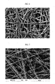
- An enlarged image of the obtained separator was photographed by Scanning Electron Microscopy (SEM) and shown in FIG. 2 .
- the compression temperature were varied into 150°C, 170°C, 190°C, 210°C, and 230°C while calendering, to thus have obtained a separator.
- Various physical properties such as tensile strength, elastic modulus, bond strength, average pore size, and air permeability of the separator were measured and shown in Table 1.
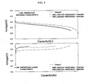
- the separator was dipped into the electrolyte of EC/DEC 1M LiPF 6 for 24 hours in order to evaluate the electrolyte impregnation performance.
- the results were taken by SEM and shown in FIG. 3 .
- Example 2 a separator was manufactured in the same manner as in Example 1, except that a spinning solution was prepared by changing a mixture ratio of PAN/PVdF into a weight ratio of 7:3.
- polyacrylonitrile (PAN) of 7.7g and polyvinylidene fluoride (PVdF) of 3.3g were added to dimethylacetamide (DMAc) of 89g, and stirred at 80 °C. to thus have prepared a spinning solution made of a heat-resistant polymer and a swelling polymer.
- Comparative Example 1 a separator was manufactured in the same manner as in Example 1, except that a spinning solution was prepared by changing a mixture ratio of PAN/PVdF into a weight ratio of 7.5:2.5.
- polyacrylonitrile (PAN) of 8.25g and polyvinylidene fluoride (PVdF) of 2.75g were added to dimethylacetamide (DMAc) of 89g, and stirred at 80°C, to thus have prepared a spinning solution made of a heat-resistant polymer and a swelling polymer.
- Comparative Example 2 a separator was manufactured in the same manner as in Example 1, except that a spinning solution was prepared by using only heat-resistant polymer PAN without having mixed a heat-resistant polymer and a swelling polymer, and then various physical properties of the obtained separator were measured and shown in Table 1.
- Comparative Example 3 a separator was manufactured in the same manner as in Example 1, except that a spinning solution was prepared by changing a mixture ratio of PAN/PVdF into a weight ratio of 3:7.
- polyacrylonitrile (PAN) of 3.3g and polyvinylidene fluoride (PVdF) of 7.7g were added to dimethylacetamide (DMAc) of 89g, and stirred at 80 °C, to thus have prepared a spinning solution made of a heat-resistant polymer and a swelling polymer.
- Example 1 Comparative Example 3 Comparative Example 4 PVdF/PAN 50/50wt% PVdF/PAN 30/70 wt% PVdF/PAN 25/75 wt% PAN 100wt% Compression temperature (°C) 150°C 170°C 190°C 210°C 230°C 190°C 190°C 190°C 190°C Tensile strength (Mpa) 23.60 23.90 21.40 26.90 27.70 23.60 17.20 19.20 Tensile expansion rate (%) 16.80 9.40 6.00 12.00 6.20 16.80 14.60 13.30 Elastic modulus (Mpa) 791.00 900.50 956.30 937.60 1118.70 791.00 538.10 719.90 Bond strength (cN/25mm) 426.30 651.20 648.20 621.60 527.60 426.30 36.20 26.70 Weight (g/m 2 ) 16.76 16.64 16.44 18.56 18.60 14.01 10.12 9.36
- calendering is made in the range of 170°C to 210°C in order to have the tensile strength, elastic modulus, and bond strength of all the resulting separators representing values of the optimum range.
- Example 1 that a weight ratio of the swelling polymer and the heat-resistant polymer was 50:50, indicates a low-temperature discharge characteristic and a low temperature charge characteristic similar to Celgard of Celgard, LLC, but Comparative Example 3 that a weight ratio of the swelling polymer and the heat-resistant polymer was 70:30, indicates that too much swelling occurred in the electrolyte and the high-temperature and low-temperature charge/discharge characteristics became worse.
- a separator made of heat-resistant nano-fibers by an air-electrospinning (AES) method, polyethersulfone (PES) of 12g and polyvinylidene fluoride (PVdF) of 8g were added to a mixed solvent of 80g obtained by mixing dimethylacetamide (DMAc) of 64g and acetone of 16g, and stirred at 100°C, to thus have prepared a spinning solution made of a heat-resistant polymer and a swelling polymer.
- PES air-electrospinning
- the spinning solution consists of different phases from each other with respect to the heat-resistant polymer and the swelling polymer. Accordingly, phase separation can occur rapidly.
- the spinning solution was put into a mixing tank stirred using a pneumatic motor to then discharge the polymer solution by 20ul/min/hole.
- temperature of the spinning section was maintained at 33°C and humidity thereof was maintained to 65%, while applying a voltage of 100KV to a nozzle of a spin nozzle pack using a high voltage generator and at the same time an air pressure of 0.2MPa to a nozzle of the spin nozzle pack, to thus have manufactured an ultrafine fiber web with a mixture of PAN and PVdF.
- the ultrafine fiber web was made to pass through a primary pre-air dry zone in which air of 30°C were circulating at a speed of 30m/sec, in a running time (RT) of 4min/m, to thereby have adjusted the solvent and moisture remaining on the surface of the ultrafine fiber web.
- the thus-adjusted ultrafine fiber web was moved to a calendering device, to thus have performed a calendering process by using heating/pressurizing rolls with conditions of temperature of 190°C and pressure of 20kgf/cm 2 .
- the ultrafine fiber web was made to pass through a secondary hot-air dryer at a temperature of 100°C and with a wind speed of 20m/sec, to thus have obtained a separator.
- the thus-obtained separator was wound on a winder.
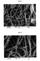
- An enlarged image of the obtained separator was photographed by Scanning Electron Microscopy (SEM) and shown in FIG. 6 .
- Polyethersulfone (PES) of 12g and polyvinylidene fluoride (PVdF) of 8g were added to dimethylacetamide (DMAc) of 80g, and stirred at 100°C, to thus have prepared a spinning solution made of a heat-resistant polymer and a swelling polymer.
- a nano-fiber web was manufactured in the same manner as in Example 3, and was made to pass through fibrous calender rolls mixed with a spray or bead before having through the calender rolls. As a result, a phenomenon of melting the nano-fiber web has occurred due to excessive beads.
- Polyethersulfone (PES) of 12g and polyvinylidene fluoride (PVdF) of 8g were added to a mixed solvent of 80g obtained by mixing dimethylacetamide (DMAc) of 24g and acetone of 56g, and stirred at 100 °C, to thus have prepared a spinning solution made of a heat-resistant polymer and a swelling polymer.
- DMAc dimethylacetamide
- nano-fiber web was manufactured by the air-electrospinning (AES) method in the same manner as in Example 3, spinning is very unstable, to thus cause the fibers to fly and to make it difficult to perform a spinning process for a long time.
- AES air-electrospinning
- a separator made of heat-resistant nano-fibers by an air-electrospinning (AES) method, polyacrylonitrile (PAN) of 5.5g and polyvinylidene fluoride (PVdF) of 5.5g were added to dimethylacetamide (DMAc) of 89, and stirred at 80°C, to thus have prepared a spinning solution made of a heat-resistant polymer and a swelling polymer.
- PAN polyacrylonitrile
- PVdF polyvinylidene fluoride
- DMAc dimethylacetamide
- the spinning solution consists of different phases from each other with respect to the heat-resistant polymer and the swelling polymer. Accordingly, phase separation can occur rapidly.
- the spinning solution was put into a mixing tank stirred using a pneumatic motor to then discharge the polymer solution by 17.5ul/min/hole.
- temperature of the spinning section was maintained at 33 °C and humidity thereof was maintained to 60%, while applying a voltage of 100KV to a nozzle of a spin nozzle pack using a high voltage generator and at the same time an air pressure of 0.25MPa to a nozzle of the spin nozzle pack, to thus have manufactured an ultrafine fiber web with a mixture of PAN and PVdF.
- the ultrafine fiber web was made to pass through a primary pre-air dry zone in which air of 30°C were circulating at a speed of 30m/sec, in a running time (RT) of 5min/m, to thereby have adjusted the solvent and moisture remaining on the surface of the ultrafine fiber web.
- the thus-adjusted ultrafine fiber web was moved to a calendering device, to thus have performed a calendering process by using heating/pressurizing rolls with conditions of temperature of 190°C and pressure of 20kgf/cm 2 .
- the ultrafine fiber web was made to pass through a secondary hot-air dryer at a temperature of 100°C and with a wind speed of 20m/sec, to thus have obtained a separator.
- the thus-obtained separator was wound on a winder.
- a separator made of heat-resistant nano-fibers was manufactured by air-electrospinning a spinning solution in the same manner as in Example 4.
- an air pressure that was applied to a nozzle of the spin nozzle pack was set to 0.05Mpa, to thus have air-electrospinned the nano-fibers.
- the air pressure of 0.05Mpa means that little air is used, to resultantly have raised spin troubles.
- Comparative Example 7 a separator was manufactured by the air-electrospinning method under the same conditions as those of Example 4, except that humidity in a spinning section was changed into 35%.
- Comparative Example 8 a separator was manufactured by the air-electrospinning method under the same conditions as those of Example 4, except that humidity in a spinning section was changed into 75%.
- the manufactured separator consisting of the heat-resistant and swelling nano-fibers was very thick in fiber diameter, and became twisty. Thus, it was difficult to lower the average pore size. As described above, if the average porosity became large, probability of micro-shorts due to the electrode active material became high. An enlarged image of the obtained separator was photographed by Scanning Electron Microscopy (SEM) and shown in FIG. 9 .
- a separator made of heat-resistant nano-fibers by an air-electrospinning (AES) method, polyacrylonitrile (PAN) of 5.5g and polyvinylidene fluoride (PVdF) of 5.5g were added to dimethylacetamide (DMAc) of 89g, and stirred at 80°C, to thus have prepared a spinning solution made of a heat-resistant polymer and a swelling polymer.
- AES air-electrospinning
- the spinning solution consists of different phases from each other with respect to the heat-resistant polymer and the swelling polymer. Accordingly, phase separation can occur rapidly.
- the spinning solution was put into a mixing tank stirred using a pneumatic motor to then discharge the polymer solution by 17.5ul/min/hole.
- temperature of the spinning section was maintained at 33°C and humidity thereof was maintained to 60%, while applying a voltage of 100KV to a nozzle of a spin nozzle pack using a high voltage generator and at the same time an air pressure of 0.25MPa to a nozzle of the spin nozzle pack, to thus have manufactured an ultrafine fiber web with a mixture of PAN and PVdF.
- the ultrafine fiber web was made to pass through a primary pre-air dry zone in which air of 30°C were circulating at a speed of 30m/sec, in a running time (RT) of 3min/m, to thereby have adjusted the solvent and moisture remaining on the surface of the ultrafine fiber web.
- a primary pre-air dry zone in which air of 30°C were circulating at a speed of 30m/sec, in a running time (RT) of 3min/m, to thereby have adjusted the solvent and moisture remaining on the surface of the ultrafine fiber web.
- the thus-adjusted ultrafine fiber web was moved to a calendering device, to thus have performed a calendering process by using heating/pressurizing rolls with the pressure condition of 20kgf/cm 2 while having varied the compression temperature into the room temperature, 70 °C, 90 °C, 110°C. 130°C, 150°C, 170°C. 190°C, 210 °C and 230 °C. Then, in order to remove the solvent and moisture that may remain, the ultrafine fiber web was made to pass through a secondary hot-air dryer at a temperature of 100°C and with a wind speed of 20m/sec, to thus have obtained a separator.
- Various physical properties such as the tensile strength, elastic modulus, bond strength, weight, thickness, average porosity, and air permeability of the thus-obtained separator were measured and shown in Table 2.
- the separator having performed the calendering process between the calendering temperatures of 170°C to 210°C showed all the appropriate values of the tensile strength, elastic modulus and bond strength, but the separator having performed the calendering process beyond the temperature range did not show all the appropriate values of the tensile strength, elastic modulus and bond strength at the same time.
- the ultrafine fiber web should undergo thermal compression at a temperature that the solvent can be completely evaporated.
- thermal compression is preferably executed at 150°C or higher to thus ensure stability of the separator. Stabilization of the separator is maintained at the time of an actual use by executing a primary pre-shrinkage.
- the heat-resistant ultrafine fibrous separator according to the present invention has a small heat-shrinkable characteristic, a heat-resistance performance, and high-strength, and forms the ultrafine fiber layer by the air-electrospinning method while removing the solvent and forming the pores. Accordingly, the heat-resistant ultrafine fibrous separator according to the present invention can be manufactured by a very simple and easy process when compared to the prior art manufacturing process.
- the present invention can be applied to a heat-resistant and high-strength separator for use in secondary batteries such as lithium-ion secondary batteries, lithium-ion polymer batteries, and super-capacitors, which require high heat-resistance and thermal stability as in hybrid electric vehicles, electric vehicles and fuel cell vehicles, and its manufacturing method.
- secondary batteries such as lithium-ion secondary batteries, lithium-ion polymer batteries, and super-capacitors, which require high heat-resistance and thermal stability as in hybrid electric vehicles, electric vehicles and fuel cell vehicles, and its manufacturing method.
Landscapes
- Chemical & Material Sciences (AREA)
- Chemical Kinetics & Catalysis (AREA)
- Electrochemistry (AREA)
- General Chemical & Material Sciences (AREA)
- Engineering & Computer Science (AREA)
- Power Engineering (AREA)
- Inorganic Chemistry (AREA)
- Manufacturing & Machinery (AREA)
- Microelectronics & Electronic Packaging (AREA)
- Materials Engineering (AREA)
- Ceramic Engineering (AREA)
- Physics & Mathematics (AREA)
- Dispersion Chemistry (AREA)
- General Physics & Mathematics (AREA)
- Condensed Matter Physics & Semiconductors (AREA)
- Composite Materials (AREA)
- Cell Separators (AREA)
- Nonwoven Fabrics (AREA)
- Electric Double-Layer Capacitors Or The Like (AREA)
- Secondary Cells (AREA)
Applications Claiming Priority (2)
| Application Number | Priority Date | Filing Date | Title |
|---|---|---|---|
| KR20090105679 | 2009-11-03 | ||
| PCT/KR2010/007706 WO2011055967A2 (ko) | 2009-11-03 | 2010-11-03 | 내열성 및 고강도 초극세 섬유상 분리막 및 그의 제조방법과 이를 이용한 이차 전지 |
Publications (3)
| Publication Number | Publication Date |
|---|---|
| EP2498320A2 EP2498320A2 (en) | 2012-09-12 |
| EP2498320A4 EP2498320A4 (en) | 2014-04-09 |
| EP2498320B1 true EP2498320B1 (en) | 2015-07-29 |
Family
ID=43970532
Family Applications (1)
| Application Number | Title | Priority Date | Filing Date |
|---|---|---|---|
| EP10828502.4A Active EP2498320B1 (en) | 2009-11-03 | 2010-11-03 | Method for manufacturing a heat-resistant and high-strength ultrafine fibrous separation layer |
Country Status (7)
| Country | Link |
|---|---|
| US (1) | US9293749B2 (ko) |
| EP (1) | EP2498320B1 (ko) |
| JP (1) | JP5924540B2 (ko) |
| KR (1) | KR101208698B1 (ko) |
| CN (1) | CN102668173B (ko) |
| RU (1) | RU2516851C2 (ko) |
| WO (1) | WO2011055967A2 (ko) |
Families Citing this family (62)
| Publication number | Priority date | Publication date | Assignee | Title |
|---|---|---|---|---|
| US8361365B2 (en) * | 2006-12-20 | 2013-01-29 | E I Du Pont De Nemours And Company | Process for electroblowing a multiple layered sheet |
| DE102011109767A1 (de) * | 2011-08-09 | 2013-02-14 | Mann + Hummel Gmbh | Verfahren zur Herstellung von Polyamid-Nanofasern mittels Elektrospinnen, Polyamid-Nanofasern, ein Filtermedium mit Polyamid-Nanofasern sowie ein Filterelement mit ei-nem solchen Filtermedium |
| CN102360950B (zh) * | 2011-09-14 | 2017-03-15 | 中国第一汽车股份有限公司 | 一种用于柔性固态超级电容器的隔膜及其制备方法 |
| WO2013066022A1 (ko) * | 2011-10-31 | 2013-05-10 | 주식회사 아모텍 | 적층형 나노섬유 웹 및 그 제조방법, 그리고 이를 이용한 나노섬유 복합재 |
| KR20140137399A (ko) * | 2012-03-02 | 2014-12-02 | 코넬 유니버시티 | 실리콘 나노합성물 나노섬유들 |
| US20150099185A1 (en) * | 2012-03-02 | 2015-04-09 | Cornell University | Lithium ion batteries comprising nanofibers |
| EP2820704A4 (en) * | 2012-03-02 | 2015-11-18 | Univ Cornell | NANOFIBERS CONTAINING LITHIUM |
| EP2828870A4 (en) | 2012-03-22 | 2016-03-30 | California Inst Of Techn | MICRO AND NANOSCALIC CAPACITORS FOR THE FORMATION OF AN ARRAY OF CONDUCTIVE ELEMENTS WITH EXTENDED BODIES |
| TWI618279B (zh) * | 2012-04-04 | 2018-03-11 | Asahi Kasei Fibers Corp | 分隔件材料 |
| JP5880295B2 (ja) * | 2012-06-05 | 2016-03-08 | ソニー株式会社 | 電気泳動素子の製造方法 |
| KR20150036108A (ko) * | 2012-06-21 | 2015-04-07 | 몰레큘라 레바 디자인 엘엘씨 | 개별 탄소 나노튜브를 사용한 에너지 저장 및 수집 장치용 바인더, 전해질 및 분리기 필름 |
| KR101551359B1 (ko) | 2012-08-21 | 2015-09-08 | 주식회사 아모그린텍 | 셧다운 기능을 갖는 복합 다공성 분리막 및 그 제조방법과 이를 이용한 이차전지 |
| US9577235B2 (en) | 2012-12-18 | 2017-02-21 | Sabic Global Technologies B.V. | High temperature melt integrity battery separators via spinning |
| US9647255B2 (en) | 2012-12-21 | 2017-05-09 | Amogreentech Co., Ltd. | Porous separation membrane, secondary battery using same, and method for manufacturing said secondary battery |
| US10164231B2 (en) * | 2013-02-05 | 2018-12-25 | Hrl Laboratories, Llc | Separators for lithium-sulfur batteries |
| KR101478982B1 (ko) * | 2013-03-12 | 2015-01-21 | 계명대학교 산학협력단 | 내오염성 나노섬유 분리막 제조방법 및 이에 의해 제조된 내오염성 나노섬유 분리막 |
| WO2014201051A1 (en) * | 2013-06-10 | 2014-12-18 | California Institute Of Technology | Systems and methods for implementing high-temperature tolerant supercapacitors |
| CN103480285B (zh) * | 2013-09-06 | 2015-10-21 | 东华大学 | 一种增强聚砜纳米纤维空气过滤膜及其静电纺丝制备方法 |
| KR101689754B1 (ko) * | 2013-10-31 | 2016-12-26 | 주식회사 엘지화학 | 이차전지의 분리막용 고강도 극세섬유 웹, 이를 포함하는 분리막 및 이의 제조 방법 |
| US9419265B2 (en) | 2013-10-31 | 2016-08-16 | Lg Chem, Ltd. | High-strength electrospun microfiber non-woven web for a separator of a secondary battery, a separator comprising the same and a method for manufacturing the same |
| CN103768959B (zh) * | 2014-01-26 | 2016-01-06 | 中国科学院重庆绿色智能技术研究院 | 亲疏水互穿网络纳米纤维、正渗透膜及制备方法 |
| CN103824988B (zh) * | 2014-02-24 | 2016-05-04 | 东华大学 | 一种复合纳米纤维锂电池隔膜及其制备方法 |
| CN104037379A (zh) * | 2014-06-06 | 2014-09-10 | 中国第一汽车股份有限公司 | 一种复合聚合物纤维隔膜及其制备方法 |
| CN104091909A (zh) * | 2014-06-25 | 2014-10-08 | 中国第一汽车股份有限公司 | 一种含有硬塑的复合聚合物纤维隔膜 |
| KR101969009B1 (ko) * | 2014-10-10 | 2019-04-15 | 주식회사 아모그린텍 | 플렉서블 배터리용 분리막, 이의 제조방법 및 이를 포함하는 플렉서블 배터리 |
| WO2016085226A1 (ko) * | 2014-11-24 | 2016-06-02 | 주식회사 아모그린텍 | 플렉서블 배터리용 분리막, 이의 제조방법 및 이를 포함하는 플렉서블 배터리 |
| CN107107546B (zh) * | 2014-12-18 | 2019-11-05 | 阿莫绿色技术有限公司 | 透湿防水面料及其制造方法 |
| CN104441908A (zh) * | 2014-12-29 | 2015-03-25 | 上海欧杰环保新材料有限公司 | 一种提高热塑性聚氨酯弹性体与聚酯纤维织物剥离强度的方法 |
| KR102050024B1 (ko) * | 2015-03-10 | 2019-11-28 | 주식회사 엘지화학 | 이차전지용 분리막의 제조방법 및 이를 이용하여 제조한 분리막 |
| EP3353844B1 (en) | 2015-03-27 | 2022-05-11 | Mason K. Harrup | All-inorganic solvents for electrolytes |
| US20160365556A1 (en) * | 2015-06-11 | 2016-12-15 | Nano And Advanced Materials Institute Limited | Nonwoven nanofiber separator and method of improving physical stability of battery separator |
| CN105206782B (zh) * | 2015-09-11 | 2017-04-05 | 江西师范大学 | PI‑Si3N4‑PTFE三元纳米复合多曲孔膜材料及其制备方法和应用 |
| CN105064001B (zh) * | 2015-09-11 | 2017-07-11 | 江西先材纳米纤维科技有限公司 | 氮化硅颗粒填充的复合多曲孔膜材料及其制备方法和应用 |
| KR101792681B1 (ko) | 2015-11-06 | 2017-11-02 | 삼성에스디아이 주식회사 | 이차 전지용 세퍼레이터 및 이를 포함하는 리튬 이차 전지 |
| KR20170140987A (ko) * | 2016-06-14 | 2017-12-22 | 삼성에스디아이 주식회사 | 리튬금속전지용 복합 전해질, 그 제조방법 및 이를 포함한 리튬금속전지 |
| CN107785519A (zh) * | 2016-08-29 | 2018-03-09 | 比亚迪股份有限公司 | 一种聚合物复合膜及其制备方法以及包括其的锂离子电池 |
| CN107799703A (zh) * | 2016-08-29 | 2018-03-13 | 比亚迪股份有限公司 | 一种聚合物复合膜及其制备方法以及包括其的锂离子电池 |
| US10707531B1 (en) | 2016-09-27 | 2020-07-07 | New Dominion Enterprises Inc. | All-inorganic solvents for electrolytes |
| US11411281B2 (en) | 2016-11-14 | 2022-08-09 | Shanghai DINHO New Material Technology Co., Ltd. | Multi-layered composite functional separator for lithium-ion battery |
| US10490843B2 (en) | 2017-04-10 | 2019-11-26 | Nano And Advanced Materials Institute Limited | Flexible battery with 180 degree operational bend radius |
| CN107340481A (zh) * | 2017-07-12 | 2017-11-10 | 浙江谷神能源科技股份有限公司 | 一种锂电池生产安全检测装置 |
| DE102017212266A1 (de) * | 2017-07-18 | 2019-01-24 | Robert Bosch Gmbh | Verfahren zum Herstellen eines Festkörperseparators für eine Batteriezelle |
| CN108417760B (zh) * | 2018-02-10 | 2021-06-11 | 郑州大学 | 一种钠/钠离子电池无纺布隔膜及其制备方法 |
| CN108511665B (zh) * | 2018-04-26 | 2021-05-04 | 广东永邦新能源股份有限公司 | 一种用于太阳能锂电池的耐温隔膜及太阳能锂电池 |
| JP7202400B2 (ja) * | 2018-08-28 | 2023-01-11 | シェンチェン シニア テクノロジー マテリアル カンパニー リミテッド | リチウムイオン電池用塗布液、リチウムイオン電池セパレータ及びリチウムイオン電池 |
| CN109786620B (zh) * | 2018-12-13 | 2022-03-15 | 武汉中兴创新材料技术有限公司 | 一种涂层薄膜及其制备方法和应用 |
| KR102628984B1 (ko) * | 2019-01-29 | 2024-01-23 | 주식회사 엘지화학 | 개선된 내열성 및 저 저항을 갖는 리튬이차전지용 폴리올레핀 분리막 및 이를 포함하는 리튬이차전지 |
| JP7298872B2 (ja) * | 2019-03-26 | 2023-06-27 | 国立大学法人信州大学 | セパレータ、セパレータの製造方法及びリチウムイオン電池 |
| JP7444561B2 (ja) * | 2019-08-08 | 2024-03-06 | 株式会社東芝 | アルミニウム電解コンデンサ、電気機器、及びアルミニウム電解コンデンサの製造方法 |
| CN112751136A (zh) * | 2019-10-31 | 2021-05-04 | 中国石油化工股份有限公司 | 一种纤维杂序交错的锂离子电池隔膜及其制备方法 |
| CN111446402A (zh) * | 2020-04-21 | 2020-07-24 | 浙江极盾新材料科技有限公司 | 一种用3d打印技术制备锂电池隔膜的工艺方法 |
| JP2021183733A (ja) * | 2020-05-21 | 2021-12-02 | 株式会社東芝 | 繊維シートの製造方法及び繊維シートの製造装置 |
| CN111916621A (zh) * | 2020-08-19 | 2020-11-10 | 北京宇程科技有限公司 | 一种锂离子电池用耐高温复合隔膜及其制备方法 |
| CN112160166B (zh) * | 2020-09-28 | 2022-11-15 | 湘潭大学 | 一种聚丙烯腈/聚环氧乙烷复合纤维膜及其制备方法和应用 |
| US11612088B2 (en) | 2020-10-28 | 2023-03-21 | Nano And Advanced Materials Institute Limited | Anisotropic heat transfer, electromagnetic interference shielding composite and method for preparation thereof |
| CN114566760A (zh) * | 2020-11-27 | 2022-05-31 | 中国石油化工股份有限公司 | 一种含有聚合物电纺纤维的锂离子电池隔膜及其制备方法 |
| CN114597593A (zh) * | 2020-12-07 | 2022-06-07 | 中国石油化工股份有限公司 | 一种含有夹心层的锂离子电池隔膜及其制备方法 |
| CN113161686B (zh) * | 2021-03-31 | 2023-03-21 | 华中科技大学 | 一种电池用复合材料夹层、其制备方法和应用 |
| CN113270689B (zh) * | 2021-05-25 | 2023-04-07 | 郑州大学 | 一种高安全电池隔膜及制备方法 |
| CN113308756A (zh) * | 2021-07-01 | 2021-08-27 | 扬州锦辉化纤有限公司 | 超细多孔锦纶6纤维及制备方法 |
| KR20230090146A (ko) | 2021-12-14 | 2023-06-21 | 한국화학연구원 | 폴리아크릴로니트릴계 공중합체와 난연제를 이용한 복합 분리막 및 이를 포함하는 전기화학소자 |
| CN117175141B (zh) * | 2023-07-31 | 2024-03-19 | 中国科学院大连化学物理研究所 | 一种锂电池隔膜及其制备方法和应用 |
Family Cites Families (17)
| Publication number | Priority date | Publication date | Assignee | Title |
|---|---|---|---|---|
| RU2140936C1 (ru) * | 1997-04-15 | 1999-11-10 | Ельяшевич Галина Казимировна | Микропористая полиэтиленовая пленка и способ ее получения |
| JP2001222988A (ja) | 2000-02-08 | 2001-08-17 | Teijin Ltd | 電解液担持ポリマー膜及びそれを用いた二次電池 |
| JP2003533862A (ja) | 2000-05-19 | 2003-11-11 | コリア インスティテュート オブ サイエンス アンド テクノロジー | 超極細繊維状の多孔性高分子セパレータフィルムを含むリチウム二次電池及びその製造方法 |
| KR20020063020A (ko) * | 2001-01-26 | 2002-08-01 | 한국과학기술연구원 | 미세 섬유상 고분자웹의 제조 방법 |
| KR100549140B1 (ko) * | 2002-03-26 | 2006-02-03 | 이 아이 듀폰 디 네모아 앤드 캄파니 | 일렉트로-브로운 방사법에 의한 초극세 나노섬유 웹제조방법 |
| JP2003327839A (ja) * | 2002-05-09 | 2003-11-19 | Mitsubishi Paper Mills Ltd | 高分子フィルムおよび電気化学素子用セパレータ |
| KR20050006540A (ko) * | 2003-07-09 | 2005-01-17 | 한국과학기술연구원 | 초극세 섬유상 다공성 고분자 분리막을 포함하는리튬이차전지 및 그 제조방법 |
| JP2005209570A (ja) | 2004-01-26 | 2005-08-04 | Teijin Ltd | 非水系二次電池用セパレータ、その製造法および非水系二次電池 |
| JP5329018B2 (ja) | 2004-08-20 | 2013-10-30 | 日産自動車株式会社 | 電池用セパレータ |
| JP4803984B2 (ja) * | 2004-09-22 | 2011-10-26 | 帝人株式会社 | リチウムイオン二次電池用セパレータおよびその製造方法とリチウムイオン二次電池 |
| KR100775310B1 (ko) * | 2004-12-22 | 2007-11-08 | 주식회사 엘지화학 | 유/무기 복합 다공성 분리막 및 이를 이용한 전기 화학소자 |
| US7112389B1 (en) * | 2005-09-30 | 2006-09-26 | E. I. Du Pont De Nemours And Company | Batteries including improved fine fiber separators |
| KR100820162B1 (ko) * | 2006-08-07 | 2008-04-10 | 한국과학기술연구원 | 내열성 초극세 섬유상 분리막 및 그 제조 방법과, 이를 이용한 이차전지 |
| KR100845239B1 (ko) * | 2006-08-07 | 2008-07-10 | 한국과학기술연구원 | 내열성 초극세 섬유층을 지닌 분리막 및 이를 이용한이차전지 |
| JP2008235047A (ja) | 2007-03-22 | 2008-10-02 | Kuraray Co Ltd | 電池用セパレータ及びその製造方法 |
| JP5334282B2 (ja) | 2008-02-20 | 2013-11-06 | 日立マクセル株式会社 | リチウム二次電池 |
| JP4872950B2 (ja) | 2008-03-05 | 2012-02-08 | ソニー株式会社 | 非水電解質二次電池 |
-
2010
- 2010-11-03 US US13/505,633 patent/US9293749B2/en active Active
- 2010-11-03 KR KR1020100108588A patent/KR101208698B1/ko active IP Right Grant
- 2010-11-03 EP EP10828502.4A patent/EP2498320B1/en active Active
- 2010-11-03 CN CN201080055584.2A patent/CN102668173B/zh active Active
- 2010-11-03 JP JP2012536708A patent/JP5924540B2/ja active Active
- 2010-11-03 RU RU2012120695/07A patent/RU2516851C2/ru active
- 2010-11-03 WO PCT/KR2010/007706 patent/WO2011055967A2/ko active Application Filing
Also Published As
| Publication number | Publication date |
|---|---|
| RU2012120695A (ru) | 2013-12-10 |
| CN102668173B (zh) | 2015-08-12 |
| RU2516851C2 (ru) | 2014-05-20 |
| CN102668173A (zh) | 2012-09-12 |
| EP2498320A4 (en) | 2014-04-09 |
| US9293749B2 (en) | 2016-03-22 |
| WO2011055967A3 (ko) | 2011-09-09 |
| JP2013510389A (ja) | 2013-03-21 |
| KR101208698B1 (ko) | 2012-12-06 |
| KR20110049715A (ko) | 2011-05-12 |
| JP5924540B2 (ja) | 2016-06-01 |
| US20120225358A1 (en) | 2012-09-06 |
| WO2011055967A2 (ko) | 2011-05-12 |
| EP2498320A2 (en) | 2012-09-12 |
Similar Documents
| Publication | Publication Date | Title |
|---|---|---|
| EP2498320B1 (en) | Method for manufacturing a heat-resistant and high-strength ultrafine fibrous separation layer | |
| US8815432B2 (en) | Heat resisting ultrafine fibrous separator and secondary battery using the same | |
| JP2013510389A5 (ko) | ||
| US10135092B2 (en) | Polymer electrolyte, lithium secondary battery using same, and method for manufacturing lithium secondary battery | |
| US9647255B2 (en) | Porous separation membrane, secondary battery using same, and method for manufacturing said secondary battery | |
| US9601740B2 (en) | Composite porous separation membrane having shut-down function, method of manufacturing same, and secondary batteries using same | |
| EP3444866B1 (en) | Separator and electrochemical device including the same | |
| US20160351876A1 (en) | Heat resisting separator having ultrafine fibrous layer and secondary battery having the same | |
| KR101283487B1 (ko) | 세퍼레이터, 그 제조방법 및 이를 구비한 전기화학소자 | |
| KR101246825B1 (ko) | 이차 전지용 내열성 분리막 및 이를 이용한 이차 전지와 그의 제조방법 | |
| KR100742959B1 (ko) | 유/무기 복합 다공성 필름 및 이를 이용하는 전기 화학소자 | |
| KR101283013B1 (ko) | 고내열성 및 고강도 초극세 섬유상 분리막 및 그의 제조방법 | |
| EP3324461A1 (en) | Separator for lithium-ion battery, manufacturing method therefor, and lithium-ion battery | |
| KR20150141403A (ko) | 복합 다공성 분리막 및 그 제조방법과 이를 이용한 이차전지 | |
| KR101601168B1 (ko) | 셧다운 기능을 갖는 복합 다공성 분리막 및 이를 이용한 이차전지 | |
| KR101551358B1 (ko) | 셧다운 기능을 갖는 복합 다공성 분리막 및 그 제조방법과 이를 이용한 이차전지 | |
| KR20060041650A (ko) | 유/무기 복합 다공성 필름 및 이를 이용한 전기 화학 소자 | |
| KR20110048921A (ko) | 내열성 및 고강도 초극세 섬유상 분리막의 제조방법 |
Legal Events
| Date | Code | Title | Description |
|---|---|---|---|
| PUAI | Public reference made under article 153(3) epc to a published international application that has entered the european phase |
Free format text: ORIGINAL CODE: 0009012 |
|
| 17P | Request for examination filed |
Effective date: 20120516 |
|
| AK | Designated contracting states |
Kind code of ref document: A2 Designated state(s): AL AT BE BG CH CY CZ DE DK EE ES FI FR GB GR HR HU IE IS IT LI LT LU LV MC MK MT NL NO PL PT RO RS SE SI SK SM TR |
|
| RIN1 | Information on inventor provided before grant (corrected) |
Inventor name: JO, BYUNG GWANG Inventor name: JUNG, YONG SIK Inventor name: KIM, YUN HYE Inventor name: SEO, IN YONG |
|
| DAX | Request for extension of the european patent (deleted) | ||
| A4 | Supplementary search report drawn up and despatched |
Effective date: 20140307 |
|
| RIC1 | Information provided on ipc code assigned before grant |
Ipc: H01M 2/16 20060101AFI20140303BHEP Ipc: H01M 10/052 20100101ALI20140303BHEP |
|
| REG | Reference to a national code |
Ref country code: DE Ref legal event code: R079 Ref document number: 602010026340 Country of ref document: DE Free format text: PREVIOUS MAIN CLASS: H01M0002160000 Ipc: H01M0002180000 |
|
| GRAP | Despatch of communication of intention to grant a patent |
Free format text: ORIGINAL CODE: EPIDOSNIGR1 |
|
| RIC1 | Information provided on ipc code assigned before grant |
Ipc: H01M 2/18 20060101AFI20150129BHEP Ipc: H01M 2/14 20060101ALI20150129BHEP Ipc: H01M 2/16 20060101ALI20150129BHEP Ipc: H01M 10/0525 20100101ALN20150129BHEP Ipc: H01G 9/02 20060101ALI20150129BHEP |
|
| RIC1 | Information provided on ipc code assigned before grant |
Ipc: H01M 2/16 20060101ALI20150217BHEP Ipc: H01M 2/18 20060101AFI20150217BHEP Ipc: H01M 10/0525 20100101ALN20150217BHEP Ipc: H01M 2/14 20060101ALI20150217BHEP Ipc: H01G 9/02 20060101ALI20150217BHEP |
|
| INTG | Intention to grant announced |
Effective date: 20150303 |
|
| RIN1 | Information on inventor provided before grant (corrected) |
Inventor name: JO, BYUNG GWANG Inventor name: JUNG, YONG SIK Inventor name: SEO, IN YONG Inventor name: KIM, YUN HYE |
|
| GRAS | Grant fee paid |
Free format text: ORIGINAL CODE: EPIDOSNIGR3 |
|
| GRAA | (expected) grant |
Free format text: ORIGINAL CODE: 0009210 |
|
| AK | Designated contracting states |
Kind code of ref document: B1 Designated state(s): AL AT BE BG CH CY CZ DE DK EE ES FI FR GB GR HR HU IE IS IT LI LT LU LV MC MK MT NL NO PL PT RO RS SE SI SK SM TR |
|
| REG | Reference to a national code |
Ref country code: GB Ref legal event code: FG4D |
|
| REG | Reference to a national code |
Ref country code: CH Ref legal event code: EP |
|
| REG | Reference to a national code |
Ref country code: AT Ref legal event code: REF Ref document number: 739909 Country of ref document: AT Kind code of ref document: T Effective date: 20150815 |
|
| REG | Reference to a national code |
Ref country code: IE Ref legal event code: FG4D |
|
| REG | Reference to a national code |
Ref country code: DE Ref legal event code: R096 Ref document number: 602010026340 Country of ref document: DE |
|
| REG | Reference to a national code |
Ref country code: FR Ref legal event code: PLFP Year of fee payment: 6 |
|
| REG | Reference to a national code |
Ref country code: AT Ref legal event code: MK05 Ref document number: 739909 Country of ref document: AT Kind code of ref document: T Effective date: 20150729 |
|
| REG | Reference to a national code |
Ref country code: LT Ref legal event code: MG4D |
|
| REG | Reference to a national code |
Ref country code: NL Ref legal event code: MP Effective date: 20150729 |
|
| PG25 | Lapsed in a contracting state [announced via postgrant information from national office to epo] |
Ref country code: LT Free format text: LAPSE BECAUSE OF FAILURE TO SUBMIT A TRANSLATION OF THE DESCRIPTION OR TO PAY THE FEE WITHIN THE PRESCRIBED TIME-LIMIT Effective date: 20150729 Ref country code: GR Free format text: LAPSE BECAUSE OF FAILURE TO SUBMIT A TRANSLATION OF THE DESCRIPTION OR TO PAY THE FEE WITHIN THE PRESCRIBED TIME-LIMIT Effective date: 20151030 Ref country code: NO Free format text: LAPSE BECAUSE OF FAILURE TO SUBMIT A TRANSLATION OF THE DESCRIPTION OR TO PAY THE FEE WITHIN THE PRESCRIBED TIME-LIMIT Effective date: 20151029 Ref country code: FI Free format text: LAPSE BECAUSE OF FAILURE TO SUBMIT A TRANSLATION OF THE DESCRIPTION OR TO PAY THE FEE WITHIN THE PRESCRIBED TIME-LIMIT Effective date: 20150729 Ref country code: LV Free format text: LAPSE BECAUSE OF FAILURE TO SUBMIT A TRANSLATION OF THE DESCRIPTION OR TO PAY THE FEE WITHIN THE PRESCRIBED TIME-LIMIT Effective date: 20150729 |
|
| PG25 | Lapsed in a contracting state [announced via postgrant information from national office to epo] |
Ref country code: SE Free format text: LAPSE BECAUSE OF FAILURE TO SUBMIT A TRANSLATION OF THE DESCRIPTION OR TO PAY THE FEE WITHIN THE PRESCRIBED TIME-LIMIT Effective date: 20150729 Ref country code: ES Free format text: LAPSE BECAUSE OF FAILURE TO SUBMIT A TRANSLATION OF THE DESCRIPTION OR TO PAY THE FEE WITHIN THE PRESCRIBED TIME-LIMIT Effective date: 20150729 Ref country code: RS Free format text: LAPSE BECAUSE OF FAILURE TO SUBMIT A TRANSLATION OF THE DESCRIPTION OR TO PAY THE FEE WITHIN THE PRESCRIBED TIME-LIMIT Effective date: 20150729 Ref country code: PL Free format text: LAPSE BECAUSE OF FAILURE TO SUBMIT A TRANSLATION OF THE DESCRIPTION OR TO PAY THE FEE WITHIN THE PRESCRIBED TIME-LIMIT Effective date: 20150729 Ref country code: AT Free format text: LAPSE BECAUSE OF FAILURE TO SUBMIT A TRANSLATION OF THE DESCRIPTION OR TO PAY THE FEE WITHIN THE PRESCRIBED TIME-LIMIT Effective date: 20150729 Ref country code: HR Free format text: LAPSE BECAUSE OF FAILURE TO SUBMIT A TRANSLATION OF THE DESCRIPTION OR TO PAY THE FEE WITHIN THE PRESCRIBED TIME-LIMIT Effective date: 20150729 Ref country code: PT Free format text: LAPSE BECAUSE OF FAILURE TO SUBMIT A TRANSLATION OF THE DESCRIPTION OR TO PAY THE FEE WITHIN THE PRESCRIBED TIME-LIMIT Effective date: 20151130 Ref country code: IS Free format text: LAPSE BECAUSE OF FAILURE TO SUBMIT A TRANSLATION OF THE DESCRIPTION OR TO PAY THE FEE WITHIN THE PRESCRIBED TIME-LIMIT Effective date: 20151129 |
|
| PG25 | Lapsed in a contracting state [announced via postgrant information from national office to epo] |
Ref country code: NL Free format text: LAPSE BECAUSE OF FAILURE TO SUBMIT A TRANSLATION OF THE DESCRIPTION OR TO PAY THE FEE WITHIN THE PRESCRIBED TIME-LIMIT Effective date: 20150729 |
|
| PG25 | Lapsed in a contracting state [announced via postgrant information from national office to epo] |
Ref country code: DK Free format text: LAPSE BECAUSE OF FAILURE TO SUBMIT A TRANSLATION OF THE DESCRIPTION OR TO PAY THE FEE WITHIN THE PRESCRIBED TIME-LIMIT Effective date: 20150729 Ref country code: CZ Free format text: LAPSE BECAUSE OF FAILURE TO SUBMIT A TRANSLATION OF THE DESCRIPTION OR TO PAY THE FEE WITHIN THE PRESCRIBED TIME-LIMIT Effective date: 20150729 Ref country code: EE Free format text: LAPSE BECAUSE OF FAILURE TO SUBMIT A TRANSLATION OF THE DESCRIPTION OR TO PAY THE FEE WITHIN THE PRESCRIBED TIME-LIMIT Effective date: 20150729 Ref country code: SK Free format text: LAPSE BECAUSE OF FAILURE TO SUBMIT A TRANSLATION OF THE DESCRIPTION OR TO PAY THE FEE WITHIN THE PRESCRIBED TIME-LIMIT Effective date: 20150729 Ref country code: IT Free format text: LAPSE BECAUSE OF FAILURE TO SUBMIT A TRANSLATION OF THE DESCRIPTION OR TO PAY THE FEE WITHIN THE PRESCRIBED TIME-LIMIT Effective date: 20150729 |
|
| REG | Reference to a national code |
Ref country code: DE Ref legal event code: R097 Ref document number: 602010026340 Country of ref document: DE |
|
| PG25 | Lapsed in a contracting state [announced via postgrant information from national office to epo] |
Ref country code: RO Free format text: LAPSE BECAUSE OF FAILURE TO SUBMIT A TRANSLATION OF THE DESCRIPTION OR TO PAY THE FEE WITHIN THE PRESCRIBED TIME-LIMIT Effective date: 20150729 |
|
| PLBE | No opposition filed within time limit |
Free format text: ORIGINAL CODE: 0009261 |
|
| STAA | Information on the status of an ep patent application or granted ep patent |
Free format text: STATUS: NO OPPOSITION FILED WITHIN TIME LIMIT |
|
| PG25 | Lapsed in a contracting state [announced via postgrant information from national office to epo] |
Ref country code: LU Free format text: LAPSE BECAUSE OF FAILURE TO SUBMIT A TRANSLATION OF THE DESCRIPTION OR TO PAY THE FEE WITHIN THE PRESCRIBED TIME-LIMIT Effective date: 20151103 Ref country code: MC Free format text: LAPSE BECAUSE OF FAILURE TO SUBMIT A TRANSLATION OF THE DESCRIPTION OR TO PAY THE FEE WITHIN THE PRESCRIBED TIME-LIMIT Effective date: 20150729 |
|
| REG | Reference to a national code |
Ref country code: CH Ref legal event code: PL |
|
| 26N | No opposition filed |
Effective date: 20160502 |
|
| PG25 | Lapsed in a contracting state [announced via postgrant information from national office to epo] |
Ref country code: CH Free format text: LAPSE BECAUSE OF NON-PAYMENT OF DUE FEES Effective date: 20151130 Ref country code: LI Free format text: LAPSE BECAUSE OF NON-PAYMENT OF DUE FEES Effective date: 20151130 |
|
| REG | Reference to a national code |
Ref country code: IE Ref legal event code: MM4A |
|
| PG25 | Lapsed in a contracting state [announced via postgrant information from national office to epo] |
Ref country code: SI Free format text: LAPSE BECAUSE OF FAILURE TO SUBMIT A TRANSLATION OF THE DESCRIPTION OR TO PAY THE FEE WITHIN THE PRESCRIBED TIME-LIMIT Effective date: 20150729 |
|
| PG25 | Lapsed in a contracting state [announced via postgrant information from national office to epo] |
Ref country code: IE Free format text: LAPSE BECAUSE OF NON-PAYMENT OF DUE FEES Effective date: 20151103 |
|
| REG | Reference to a national code |
Ref country code: FR Ref legal event code: PLFP Year of fee payment: 7 |
|
| PG25 | Lapsed in a contracting state [announced via postgrant information from national office to epo] |
Ref country code: BE Free format text: LAPSE BECAUSE OF FAILURE TO SUBMIT A TRANSLATION OF THE DESCRIPTION OR TO PAY THE FEE WITHIN THE PRESCRIBED TIME-LIMIT Effective date: 20150729 |
|
| PG25 | Lapsed in a contracting state [announced via postgrant information from national office to epo] |
Ref country code: SM Free format text: LAPSE BECAUSE OF FAILURE TO SUBMIT A TRANSLATION OF THE DESCRIPTION OR TO PAY THE FEE WITHIN THE PRESCRIBED TIME-LIMIT Effective date: 20150729 Ref country code: BG Free format text: LAPSE BECAUSE OF FAILURE TO SUBMIT A TRANSLATION OF THE DESCRIPTION OR TO PAY THE FEE WITHIN THE PRESCRIBED TIME-LIMIT Effective date: 20150729 Ref country code: HU Free format text: LAPSE BECAUSE OF FAILURE TO SUBMIT A TRANSLATION OF THE DESCRIPTION OR TO PAY THE FEE WITHIN THE PRESCRIBED TIME-LIMIT; INVALID AB INITIO Effective date: 20101103 |
|
| PG25 | Lapsed in a contracting state [announced via postgrant information from national office to epo] |
Ref country code: CY Free format text: LAPSE BECAUSE OF FAILURE TO SUBMIT A TRANSLATION OF THE DESCRIPTION OR TO PAY THE FEE WITHIN THE PRESCRIBED TIME-LIMIT Effective date: 20150729 |
|
| PG25 | Lapsed in a contracting state [announced via postgrant information from national office to epo] |
Ref country code: MT Free format text: LAPSE BECAUSE OF FAILURE TO SUBMIT A TRANSLATION OF THE DESCRIPTION OR TO PAY THE FEE WITHIN THE PRESCRIBED TIME-LIMIT Effective date: 20150729 Ref country code: TR Free format text: LAPSE BECAUSE OF FAILURE TO SUBMIT A TRANSLATION OF THE DESCRIPTION OR TO PAY THE FEE WITHIN THE PRESCRIBED TIME-LIMIT Effective date: 20150729 |
|
| REG | Reference to a national code |
Ref country code: FR Ref legal event code: PLFP Year of fee payment: 8 |
|
| PG25 | Lapsed in a contracting state [announced via postgrant information from national office to epo] |
Ref country code: MK Free format text: LAPSE BECAUSE OF FAILURE TO SUBMIT A TRANSLATION OF THE DESCRIPTION OR TO PAY THE FEE WITHIN THE PRESCRIBED TIME-LIMIT Effective date: 20150729 |
|
| REG | Reference to a national code |
Ref country code: FR Ref legal event code: PLFP Year of fee payment: 9 |
|
| PG25 | Lapsed in a contracting state [announced via postgrant information from national office to epo] |
Ref country code: AL Free format text: LAPSE BECAUSE OF FAILURE TO SUBMIT A TRANSLATION OF THE DESCRIPTION OR TO PAY THE FEE WITHIN THE PRESCRIBED TIME-LIMIT Effective date: 20150729 |
|
| REG | Reference to a national code |
Ref country code: DE Ref legal event code: R079 Ref document number: 602010026340 Country of ref document: DE Free format text: PREVIOUS MAIN CLASS: H01M0002180000 Ipc: H01M0050463000 |
|
| PGFP | Annual fee paid to national office [announced via postgrant information from national office to epo] |
Ref country code: GB Payment date: 20231023 Year of fee payment: 14 |
|
| PGFP | Annual fee paid to national office [announced via postgrant information from national office to epo] |
Ref country code: FR Payment date: 20231024 Year of fee payment: 14 Ref country code: DE Payment date: 20231023 Year of fee payment: 14 |