EP2439239A1 - Ethylenharzzusammensetzung, solarzellen-dichtungsmaterial und solarzellenmodul mit dem dichtungsmaterial - Google Patents
Ethylenharzzusammensetzung, solarzellen-dichtungsmaterial und solarzellenmodul mit dem dichtungsmaterial Download PDFInfo
- Publication number
- EP2439239A1 EP2439239A1 EP10783131A EP10783131A EP2439239A1 EP 2439239 A1 EP2439239 A1 EP 2439239A1 EP 10783131 A EP10783131 A EP 10783131A EP 10783131 A EP10783131 A EP 10783131A EP 2439239 A1 EP2439239 A1 EP 2439239A1
- Authority
- EP
- European Patent Office
- Prior art keywords
- ethylene
- ethylene polymer
- resin composition
- sheet
- encapsulant material
- Prior art date
- Legal status (The legal status is an assumption and is not a legal conclusion. Google has not performed a legal analysis and makes no representation as to the accuracy of the status listed.)
- Granted
Links
- VGGSQFUCUMXWEO-UHFFFAOYSA-N Ethene Chemical compound C=C VGGSQFUCUMXWEO-UHFFFAOYSA-N 0.000 title claims abstract description 326
- 239000005977 Ethylene Substances 0.000 title claims abstract description 326
- 239000011342 resin composition Substances 0.000 title claims abstract description 136
- 239000003566 sealing material Substances 0.000 title 2
- 229920000573 polyethylene Polymers 0.000 claims abstract description 381
- -1 unsaturated silane compound Chemical class 0.000 claims abstract description 140
- 229910052751 metal Inorganic materials 0.000 claims abstract description 65
- 239000002184 metal Substances 0.000 claims abstract description 62
- 239000008393 encapsulating agent Substances 0.000 claims description 214
- 239000000463 material Substances 0.000 claims description 179
- 239000004711 α-olefin Substances 0.000 claims description 160
- 229920000089 Cyclic olefin copolymer Polymers 0.000 claims description 130
- 239000010409 thin film Substances 0.000 claims description 67
- 230000001681 protective effect Effects 0.000 claims description 62
- 239000000203 mixture Substances 0.000 claims description 57
- 239000008188 pellet Substances 0.000 claims description 40
- 239000003381 stabilizer Substances 0.000 claims description 39
- 150000001451 organic peroxides Chemical class 0.000 claims description 37
- 238000001125 extrusion Methods 0.000 claims description 33
- 238000003860 storage Methods 0.000 claims description 32
- 229910000077 silane Inorganic materials 0.000 claims description 28
- BLRPTPMANUNPDV-UHFFFAOYSA-N Silane Chemical compound [SiH4] BLRPTPMANUNPDV-UHFFFAOYSA-N 0.000 claims description 27
- 239000000843 powder Substances 0.000 claims description 23
- 239000000654 additive Substances 0.000 claims description 21
- 239000006096 absorbing agent Substances 0.000 claims description 16
- 239000004611 light stabiliser Substances 0.000 claims description 6
- 230000000996 additive effect Effects 0.000 claims description 5
- 238000000034 method Methods 0.000 abstract description 88
- 230000008569 process Effects 0.000 abstract description 67
- 238000004132 cross linking Methods 0.000 abstract description 21
- 239000000155 melt Substances 0.000 abstract description 14
- 238000002844 melting Methods 0.000 abstract description 5
- 230000008018 melting Effects 0.000 abstract description 5
- 210000004027 cell Anatomy 0.000 description 280
- 238000006116 polymerization reaction Methods 0.000 description 143
- 239000010410 layer Substances 0.000 description 129
- 239000011521 glass Substances 0.000 description 97
- 150000001875 compounds Chemical class 0.000 description 72
- VLKZOEOYAKHREP-UHFFFAOYSA-N n-Hexane Chemical compound CCCCCC VLKZOEOYAKHREP-UHFFFAOYSA-N 0.000 description 68
- 238000012360 testing method Methods 0.000 description 54
- 229920002959 polymer blend Polymers 0.000 description 50
- 239000001257 hydrogen Substances 0.000 description 45
- 229910052739 hydrogen Inorganic materials 0.000 description 45
- 239000000047 product Substances 0.000 description 44
- UFHFLCQGNIYNRP-UHFFFAOYSA-N Hydrogen Chemical compound [H][H] UFHFLCQGNIYNRP-UHFFFAOYSA-N 0.000 description 42
- LIKMAJRDDDTEIG-UHFFFAOYSA-N 1-hexene Chemical compound CCCCC=C LIKMAJRDDDTEIG-UHFFFAOYSA-N 0.000 description 40
- 238000003475 lamination Methods 0.000 description 40
- BQCADISMDOOEFD-UHFFFAOYSA-N Silver Chemical compound [Ag] BQCADISMDOOEFD-UHFFFAOYSA-N 0.000 description 33
- 229910052709 silver Inorganic materials 0.000 description 33
- 239000004332 silver Substances 0.000 description 33
- XUIMIQQOPSSXEZ-UHFFFAOYSA-N Silicon Chemical compound [Si] XUIMIQQOPSSXEZ-UHFFFAOYSA-N 0.000 description 31
- 229910052710 silicon Inorganic materials 0.000 description 31
- 239000010703 silicon Substances 0.000 description 31
- VYPSYNLAJGMNEJ-UHFFFAOYSA-N Silicium dioxide Chemical compound O=[Si]=O VYPSYNLAJGMNEJ-UHFFFAOYSA-N 0.000 description 28
- 230000014759 maintenance of location Effects 0.000 description 28
- 238000000465 moulding Methods 0.000 description 28
- YXFVVABEGXRONW-UHFFFAOYSA-N Toluene Chemical compound CC1=CC=CC=C1 YXFVVABEGXRONW-UHFFFAOYSA-N 0.000 description 27
- 229920005989 resin Polymers 0.000 description 27
- 239000011347 resin Substances 0.000 description 27
- VXNZUUAINFGPBY-UHFFFAOYSA-N 1-Butene Chemical compound CCC=C VXNZUUAINFGPBY-UHFFFAOYSA-N 0.000 description 24
- 239000007789 gas Substances 0.000 description 24
- 239000003054 catalyst Substances 0.000 description 23
- 238000006243 chemical reaction Methods 0.000 description 22
- 239000010408 film Substances 0.000 description 22
- 239000000499 gel Substances 0.000 description 22
- 230000015556 catabolic process Effects 0.000 description 19
- 238000010438 heat treatment Methods 0.000 description 19
- 238000004519 manufacturing process Methods 0.000 description 19
- 230000007797 corrosion Effects 0.000 description 18
- 238000005260 corrosion Methods 0.000 description 18
- 238000009826 distribution Methods 0.000 description 18
- 239000005038 ethylene vinyl acetate Substances 0.000 description 18
- DQXBYHZEEUGOBF-UHFFFAOYSA-N but-3-enoic acid;ethene Chemical compound C=C.OC(=O)CC=C DQXBYHZEEUGOBF-UHFFFAOYSA-N 0.000 description 17
- 238000010528 free radical solution polymerization reaction Methods 0.000 description 17
- 230000001965 increasing effect Effects 0.000 description 17
- 230000007774 longterm Effects 0.000 description 17
- 229920001200 poly(ethylene-vinyl acetate) Polymers 0.000 description 17
- 229910052782 aluminium Inorganic materials 0.000 description 16
- 230000004048 modification Effects 0.000 description 16
- 238000012986 modification Methods 0.000 description 16
- 239000000758 substrate Substances 0.000 description 16
- KWKAKUADMBZCLK-UHFFFAOYSA-N 1-octene Chemical compound CCCCCCC=C KWKAKUADMBZCLK-UHFFFAOYSA-N 0.000 description 15
- 230000007423 decrease Effects 0.000 description 15
- 229920000642 polymer Polymers 0.000 description 15
- 229920001577 copolymer Polymers 0.000 description 14
- 239000002685 polymerization catalyst Substances 0.000 description 14
- 239000000377 silicon dioxide Substances 0.000 description 14
- 229910052726 zirconium Inorganic materials 0.000 description 14
- JKIJEFPNVSHHEI-UHFFFAOYSA-N Phenol, 2,4-bis(1,1-dimethylethyl)-, phosphite (3:1) Chemical compound CC(C)(C)C1=CC(C(C)(C)C)=CC=C1OP(OC=1C(=CC(=CC=1)C(C)(C)C)C(C)(C)C)OC1=CC=C(C(C)(C)C)C=C1C(C)(C)C JKIJEFPNVSHHEI-UHFFFAOYSA-N 0.000 description 13
- QCWXUUIWCKQGHC-UHFFFAOYSA-N Zirconium Chemical compound [Zr] QCWXUUIWCKQGHC-UHFFFAOYSA-N 0.000 description 13
- 125000005370 alkoxysilyl group Chemical group 0.000 description 13
- 238000004049 embossing Methods 0.000 description 13
- 229920000139 polyethylene terephthalate Polymers 0.000 description 13
- 239000005020 polyethylene terephthalate Substances 0.000 description 13
- 230000037048 polymerization activity Effects 0.000 description 12
- 239000000243 solution Substances 0.000 description 12
- 229910052724 xenon Inorganic materials 0.000 description 12
- FHNFHKCVQCLJFQ-UHFFFAOYSA-N xenon atom Chemical compound [Xe] FHNFHKCVQCLJFQ-UHFFFAOYSA-N 0.000 description 12
- 238000013329 compounding Methods 0.000 description 11
- 238000010248 power generation Methods 0.000 description 11
- 239000002516 radical scavenger Substances 0.000 description 11
- 239000000126 substance Substances 0.000 description 11
- XLYOFNOQVPJJNP-UHFFFAOYSA-N water Substances O XLYOFNOQVPJJNP-UHFFFAOYSA-N 0.000 description 11
- XAGFODPZIPBFFR-UHFFFAOYSA-N aluminium Chemical compound [Al] XAGFODPZIPBFFR-UHFFFAOYSA-N 0.000 description 10
- 229910021419 crystalline silicon Inorganic materials 0.000 description 10
- TVMXDCGIABBOFY-UHFFFAOYSA-N n-Octanol Natural products CCCCCCCC TVMXDCGIABBOFY-UHFFFAOYSA-N 0.000 description 10
- YWAKXRMUMFPDSH-UHFFFAOYSA-N pentene Chemical compound CCCC=C YWAKXRMUMFPDSH-UHFFFAOYSA-N 0.000 description 10
- 230000035699 permeability Effects 0.000 description 10
- 230000000704 physical effect Effects 0.000 description 10
- 230000009467 reduction Effects 0.000 description 10
- WSSSPWUEQFSQQG-UHFFFAOYSA-N 4-methyl-1-pentene Chemical compound CC(C)CC=C WSSSPWUEQFSQQG-UHFFFAOYSA-N 0.000 description 9
- 239000004793 Polystyrene Substances 0.000 description 9
- 239000000853 adhesive Substances 0.000 description 9
- 230000001070 adhesive effect Effects 0.000 description 9
- 230000000903 blocking effect Effects 0.000 description 9
- 229920002223 polystyrene Polymers 0.000 description 9
- 238000004544 sputter deposition Methods 0.000 description 9
- 230000000052 comparative effect Effects 0.000 description 8
- IBKNSIPMTGYUNZ-UHFFFAOYSA-N ethenyl(methoxy)silane Chemical compound CO[SiH2]C=C IBKNSIPMTGYUNZ-UHFFFAOYSA-N 0.000 description 8
- 238000005227 gel permeation chromatography Methods 0.000 description 8
- 239000002253 acid Substances 0.000 description 7
- 150000001336 alkenes Chemical class 0.000 description 7
- 238000005229 chemical vapour deposition Methods 0.000 description 7
- 230000000694 effects Effects 0.000 description 7
- 229930195733 hydrocarbon Natural products 0.000 description 7
- 238000005259 measurement Methods 0.000 description 7
- 238000002156 mixing Methods 0.000 description 7
- JRZJOMJEPLMPRA-UHFFFAOYSA-N olefin Natural products CCCCCCCC=C JRZJOMJEPLMPRA-UHFFFAOYSA-N 0.000 description 7
- 229920005672 polyolefin resin Polymers 0.000 description 7
- 238000003825 pressing Methods 0.000 description 7
- 230000002829 reductive effect Effects 0.000 description 7
- 229910052703 rhodium Inorganic materials 0.000 description 7
- 239000011949 solid catalyst Substances 0.000 description 7
- 239000002904 solvent Substances 0.000 description 7
- MYRTYDVEIRVNKP-UHFFFAOYSA-N 1,2-Divinylbenzene Chemical compound C=CC1=CC=CC=C1C=C MYRTYDVEIRVNKP-UHFFFAOYSA-N 0.000 description 6
- AFFLGGQVNFXPEV-UHFFFAOYSA-N 1-decene Chemical compound CCCCCCCCC=C AFFLGGQVNFXPEV-UHFFFAOYSA-N 0.000 description 6
- CRSBERNSMYQZNG-UHFFFAOYSA-N 1-dodecene Chemical compound CCCCCCCCCCC=C CRSBERNSMYQZNG-UHFFFAOYSA-N 0.000 description 6
- UHOVQNZJYSORNB-UHFFFAOYSA-N Benzene Chemical compound C1=CC=CC=C1 UHOVQNZJYSORNB-UHFFFAOYSA-N 0.000 description 6
- RGSFGYAAUTVSQA-UHFFFAOYSA-N Cyclopentane Chemical compound C1CCCC1 RGSFGYAAUTVSQA-UHFFFAOYSA-N 0.000 description 6
- YMWUJEATGCHHMB-UHFFFAOYSA-N Dichloromethane Chemical compound ClCCl YMWUJEATGCHHMB-UHFFFAOYSA-N 0.000 description 6
- OKKJLVBELUTLKV-UHFFFAOYSA-N Methanol Chemical compound OC OKKJLVBELUTLKV-UHFFFAOYSA-N 0.000 description 6
- 230000001133 acceleration Effects 0.000 description 6
- 238000013459 approach Methods 0.000 description 6
- 238000006482 condensation reaction Methods 0.000 description 6
- DIOQZVSQGTUSAI-UHFFFAOYSA-N decane Chemical compound CCCCCCCCCC DIOQZVSQGTUSAI-UHFFFAOYSA-N 0.000 description 6
- 238000010292 electrical insulation Methods 0.000 description 6
- QUAMTGJKVDWJEQ-UHFFFAOYSA-N octabenzone Chemical compound OC1=CC(OCCCCCCCC)=CC=C1C(=O)C1=CC=CC=C1 QUAMTGJKVDWJEQ-UHFFFAOYSA-N 0.000 description 6
- OJMIONKXNSYLSR-UHFFFAOYSA-N phosphorous acid Chemical compound OP(O)O OJMIONKXNSYLSR-UHFFFAOYSA-N 0.000 description 6
- QQONPFPTGQHPMA-UHFFFAOYSA-N propylene Natural products CC=C QQONPFPTGQHPMA-UHFFFAOYSA-N 0.000 description 6
- 239000011241 protective layer Substances 0.000 description 6
- 238000000926 separation method Methods 0.000 description 6
- 239000007787 solid Substances 0.000 description 6
- DMWVYCCGCQPJEA-UHFFFAOYSA-N 2,5-bis(tert-butylperoxy)-2,5-dimethylhexane Chemical compound CC(C)(C)OOC(C)(C)CCC(C)(C)OOC(C)(C)C DMWVYCCGCQPJEA-UHFFFAOYSA-N 0.000 description 5
- YCKRFDGAMUMZLT-UHFFFAOYSA-N Fluorine atom Chemical compound [F] YCKRFDGAMUMZLT-UHFFFAOYSA-N 0.000 description 5
- CTQNGGLPUBDAKN-UHFFFAOYSA-N O-Xylene Chemical compound CC1=CC=CC=C1C CTQNGGLPUBDAKN-UHFFFAOYSA-N 0.000 description 5
- 229910021417 amorphous silicon Inorganic materials 0.000 description 5
- 125000004429 atom Chemical group 0.000 description 5
- 230000015572 biosynthetic process Effects 0.000 description 5
- 239000002738 chelating agent Substances 0.000 description 5
- 238000007334 copolymerization reaction Methods 0.000 description 5
- 238000006731 degradation reaction Methods 0.000 description 5
- 239000011737 fluorine Substances 0.000 description 5
- 229910052731 fluorine Inorganic materials 0.000 description 5
- 239000011888 foil Substances 0.000 description 5
- 150000002500 ions Chemical class 0.000 description 5
- OFBQJSOFQDEBGM-UHFFFAOYSA-N n-pentane Natural products CCCCC OFBQJSOFQDEBGM-UHFFFAOYSA-N 0.000 description 5
- 239000002245 particle Substances 0.000 description 5
- 229920006254 polymer film Polymers 0.000 description 5
- 229920000098 polyolefin Polymers 0.000 description 5
- 230000000717 retained effect Effects 0.000 description 5
- 239000004065 semiconductor Substances 0.000 description 5
- 239000002002 slurry Substances 0.000 description 5
- 238000003786 synthesis reaction Methods 0.000 description 5
- RFFLAFLAYFXFSW-UHFFFAOYSA-N 1,2-dichlorobenzene Chemical compound ClC1=CC=CC=C1Cl RFFLAFLAYFXFSW-UHFFFAOYSA-N 0.000 description 4
- NIXOWILDQLNWCW-UHFFFAOYSA-N 2-Propenoic acid Natural products OC(=O)C=C NIXOWILDQLNWCW-UHFFFAOYSA-N 0.000 description 4
- KBQVDAIIQCXKPI-UHFFFAOYSA-N 3-trimethoxysilylpropyl prop-2-enoate Chemical compound CO[Si](OC)(OC)CCCOC(=O)C=C KBQVDAIIQCXKPI-UHFFFAOYSA-N 0.000 description 4
- CSCPPACGZOOCGX-UHFFFAOYSA-N Acetone Chemical compound CC(C)=O CSCPPACGZOOCGX-UHFFFAOYSA-N 0.000 description 4
- NIXOWILDQLNWCW-UHFFFAOYSA-M Acrylate Chemical compound [O-]C(=O)C=C NIXOWILDQLNWCW-UHFFFAOYSA-M 0.000 description 4
- 239000004215 Carbon black (E152) Substances 0.000 description 4
- VZCYOOQTPOCHFL-OWOJBTEDSA-N Fumaric acid Chemical compound OC(=O)\C=C\C(O)=O VZCYOOQTPOCHFL-OWOJBTEDSA-N 0.000 description 4
- BAPJBEWLBFYGME-UHFFFAOYSA-N Methyl acrylate Chemical compound COC(=O)C=C BAPJBEWLBFYGME-UHFFFAOYSA-N 0.000 description 4
- IMNFDUFMRHMDMM-UHFFFAOYSA-N N-Heptane Chemical compound CCCCCCC IMNFDUFMRHMDMM-UHFFFAOYSA-N 0.000 description 4
- PPBRXRYQALVLMV-UHFFFAOYSA-N Styrene Chemical compound C=CC1=CC=CC=C1 PPBRXRYQALVLMV-UHFFFAOYSA-N 0.000 description 4
- 239000007983 Tris buffer Substances 0.000 description 4
- XTXRWKRVRITETP-UHFFFAOYSA-N Vinyl acetate Chemical compound CC(=O)OC=C XTXRWKRVRITETP-UHFFFAOYSA-N 0.000 description 4
- 150000001338 aliphatic hydrocarbons Chemical class 0.000 description 4
- MVPPADPHJFYWMZ-UHFFFAOYSA-N chlorobenzene Chemical compound ClC1=CC=CC=C1 MVPPADPHJFYWMZ-UHFFFAOYSA-N 0.000 description 4
- 238000010924 continuous production Methods 0.000 description 4
- 230000008878 coupling Effects 0.000 description 4
- 238000010168 coupling process Methods 0.000 description 4
- 238000005859 coupling reaction Methods 0.000 description 4
- LPIQUOYDBNQMRZ-UHFFFAOYSA-N cyclopentene Chemical compound C1CC=CC1 LPIQUOYDBNQMRZ-UHFFFAOYSA-N 0.000 description 4
- SNRUBQQJIBEYMU-UHFFFAOYSA-N dodecane Chemical compound CCCCCCCCCCCC SNRUBQQJIBEYMU-UHFFFAOYSA-N 0.000 description 4
- 238000012685 gas phase polymerization Methods 0.000 description 4
- 150000002430 hydrocarbons Chemical class 0.000 description 4
- 238000004898 kneading Methods 0.000 description 4
- 239000007791 liquid phase Substances 0.000 description 4
- FPYJFEHAWHCUMM-UHFFFAOYSA-N maleic anhydride Chemical compound O=C1OC(=O)C=C1 FPYJFEHAWHCUMM-UHFFFAOYSA-N 0.000 description 4
- 150000002739 metals Chemical class 0.000 description 4
- GDOPTJXRTPNYNR-UHFFFAOYSA-N methylcyclopentane Chemical compound CC1CCCC1 GDOPTJXRTPNYNR-UHFFFAOYSA-N 0.000 description 4
- 239000000178 monomer Substances 0.000 description 4
- 239000012071 phase Substances 0.000 description 4
- 125000004805 propylene group Chemical group [H]C([H])([H])C([H])([*:1])C([H])([H])[*:2] 0.000 description 4
- 238000011002 quantification Methods 0.000 description 4
- 230000035484 reaction time Effects 0.000 description 4
- 239000010935 stainless steel Substances 0.000 description 4
- 229910001220 stainless steel Inorganic materials 0.000 description 4
- XOLBLPGZBRYERU-UHFFFAOYSA-N tin dioxide Chemical compound O=[Sn]=O XOLBLPGZBRYERU-UHFFFAOYSA-N 0.000 description 4
- 239000010936 titanium Substances 0.000 description 4
- MCULRUJILOGHCJ-UHFFFAOYSA-N triisobutylaluminium Chemical compound CC(C)C[Al](CC(C)C)CC(C)C MCULRUJILOGHCJ-UHFFFAOYSA-N 0.000 description 4
- 150000007934 α,β-unsaturated carboxylic acids Chemical class 0.000 description 4
- QEQBMZQFDDDTPN-UHFFFAOYSA-N (2-methylpropan-2-yl)oxy benzenecarboperoxoate Chemical compound CC(C)(C)OOOC(=O)C1=CC=CC=C1 QEQBMZQFDDDTPN-UHFFFAOYSA-N 0.000 description 3
- YHQXBTXEYZIYOV-UHFFFAOYSA-N 3-methylbut-1-ene Chemical compound CC(C)C=C YHQXBTXEYZIYOV-UHFFFAOYSA-N 0.000 description 3
- QTBSBXVTEAMEQO-UHFFFAOYSA-N Acetic acid Chemical compound CC(O)=O QTBSBXVTEAMEQO-UHFFFAOYSA-N 0.000 description 3
- JJDZBQREKCLIOM-UHFFFAOYSA-L CC1=CC(C=C1)[Zr](Cl)(Cl)(C1C=CC(C)=C1)=[Si](C)C Chemical compound CC1=CC(C=C1)[Zr](Cl)(Cl)(C1C=CC(C)=C1)=[Si](C)C JJDZBQREKCLIOM-UHFFFAOYSA-L 0.000 description 3
- CBENFWSGALASAD-UHFFFAOYSA-N Ozone Chemical compound [O-][O+]=O CBENFWSGALASAD-UHFFFAOYSA-N 0.000 description 3
- 239000002033 PVDF binder Substances 0.000 description 3
- RTAQQCXQSZGOHL-UHFFFAOYSA-N Titanium Chemical compound [Ti] RTAQQCXQSZGOHL-UHFFFAOYSA-N 0.000 description 3
- XLOMVQKBTHCTTD-UHFFFAOYSA-N Zinc monoxide Chemical compound [Zn]=O XLOMVQKBTHCTTD-UHFFFAOYSA-N 0.000 description 3
- 239000003513 alkali Substances 0.000 description 3
- 150000004945 aromatic hydrocarbons Chemical class 0.000 description 3
- 239000002585 base Substances 0.000 description 3
- XITRBUPOXXBIJN-UHFFFAOYSA-N bis(2,2,6,6-tetramethylpiperidin-4-yl) decanedioate Chemical compound C1C(C)(C)NC(C)(C)CC1OC(=O)CCCCCCCCC(=O)OC1CC(C)(C)NC(C)(C)C1 XITRBUPOXXBIJN-UHFFFAOYSA-N 0.000 description 3
- 229920001400 block copolymer Polymers 0.000 description 3
- 238000009835 boiling Methods 0.000 description 3
- 229920005549 butyl rubber Polymers 0.000 description 3
- 230000003197 catalytic effect Effects 0.000 description 3
- 230000008859 change Effects 0.000 description 3
- 229910052802 copper Inorganic materials 0.000 description 3
- 239000010949 copper Substances 0.000 description 3
- 238000003851 corona treatment Methods 0.000 description 3
- 238000005336 cracking Methods 0.000 description 3
- 230000003247 decreasing effect Effects 0.000 description 3
- 125000004386 diacrylate group Chemical group 0.000 description 3
- 229940069096 dodecene Drugs 0.000 description 3
- 238000003379 elimination reaction Methods 0.000 description 3
- FWDBOZPQNFPOLF-UHFFFAOYSA-N ethenyl(triethoxy)silane Chemical compound CCO[Si](OCC)(OCC)C=C FWDBOZPQNFPOLF-UHFFFAOYSA-N 0.000 description 3
- 230000009969 flowable effect Effects 0.000 description 3
- 230000007062 hydrolysis Effects 0.000 description 3
- 238000006460 hydrolysis reaction Methods 0.000 description 3
- 125000002887 hydroxy group Chemical group [H]O* 0.000 description 3
- 238000001746 injection moulding Methods 0.000 description 3
- 229910052809 inorganic oxide Inorganic materials 0.000 description 3
- 239000011859 microparticle Substances 0.000 description 3
- 238000009832 plasma treatment Methods 0.000 description 3
- 229920000728 polyester Polymers 0.000 description 3
- 239000004645 polyester resin Substances 0.000 description 3
- 229920001225 polyester resin Polymers 0.000 description 3
- 229920002981 polyvinylidene fluoride Polymers 0.000 description 3
- DLSMLZRPNPCXGY-UHFFFAOYSA-N tert-butylperoxy 2-ethylhexyl carbonate Chemical compound CCCCC(CC)COC(=O)OOOC(C)(C)C DLSMLZRPNPCXGY-UHFFFAOYSA-N 0.000 description 3
- BFKJFAAPBSQJPD-UHFFFAOYSA-N tetrafluoroethene Chemical group FC(F)=C(F)F BFKJFAAPBSQJPD-UHFFFAOYSA-N 0.000 description 3
- 229910052719 titanium Inorganic materials 0.000 description 3
- 238000002834 transmittance Methods 0.000 description 3
- 125000000391 vinyl group Chemical group [H]C([*])=C([H])[H] 0.000 description 3
- 229920002554 vinyl polymer Polymers 0.000 description 3
- 239000003643 water by type Substances 0.000 description 3
- 239000008096 xylene Substances 0.000 description 3
- OJOWICOBYCXEKR-APPZFPTMSA-N (1S,4R)-5-ethylidenebicyclo[2.2.1]hept-2-ene Chemical compound CC=C1C[C@@H]2C[C@@H]1C=C2 OJOWICOBYCXEKR-APPZFPTMSA-N 0.000 description 2
- WYTZZXDRDKSJID-UHFFFAOYSA-N (3-aminopropyl)triethoxysilane Chemical compound CCO[Si](OCC)(OCC)CCCN WYTZZXDRDKSJID-UHFFFAOYSA-N 0.000 description 2
- WSLDOOZREJYCGB-UHFFFAOYSA-N 1,2-Dichloroethane Chemical compound ClCCCl WSLDOOZREJYCGB-UHFFFAOYSA-N 0.000 description 2
- KTZVZZJJVJQZHV-UHFFFAOYSA-N 1-chloro-4-ethenylbenzene Chemical compound ClC1=CC=C(C=C)C=C1 KTZVZZJJVJQZHV-UHFFFAOYSA-N 0.000 description 2
- NVZWEEGUWXZOKI-UHFFFAOYSA-N 1-ethenyl-2-methylbenzene Chemical compound CC1=CC=CC=C1C=C NVZWEEGUWXZOKI-UHFFFAOYSA-N 0.000 description 2
- JZHGRUMIRATHIU-UHFFFAOYSA-N 1-ethenyl-3-methylbenzene Chemical compound CC1=CC=CC(C=C)=C1 JZHGRUMIRATHIU-UHFFFAOYSA-N 0.000 description 2
- GQEZCXVZFLOKMC-UHFFFAOYSA-N 1-hexadecene Chemical compound CCCCCCCCCCCCCCC=C GQEZCXVZFLOKMC-UHFFFAOYSA-N 0.000 description 2
- WAUKBOOEPYNAGU-UHFFFAOYSA-N 1-phenylprop-2-enyl acetate Chemical compound CC(=O)OC(C=C)C1=CC=CC=C1 WAUKBOOEPYNAGU-UHFFFAOYSA-N 0.000 description 2
- HFDVRLIODXPAHB-UHFFFAOYSA-N 1-tetradecene Chemical compound CCCCCCCCCCCCC=C HFDVRLIODXPAHB-UHFFFAOYSA-N 0.000 description 2
- VVFNNEKHSFZNKA-UHFFFAOYSA-N 2,5-bis(tert-butylperoxy)-2,5-dimethylhex-3-ene Chemical compound CC(C)(C)OOC(C)(C)C=CC(C)(C)OOC(C)(C)C VVFNNEKHSFZNKA-UHFFFAOYSA-N 0.000 description 2
- SMZOUWXMTYCWNB-UHFFFAOYSA-N 2-(2-methoxy-5-methylphenyl)ethanamine Chemical compound COC1=CC=C(C)C=C1CCN SMZOUWXMTYCWNB-UHFFFAOYSA-N 0.000 description 2
- LEJBBGNFPAFPKQ-UHFFFAOYSA-N 2-(2-prop-2-enoyloxyethoxy)ethyl prop-2-enoate Chemical compound C=CC(=O)OCCOCCOC(=O)C=C LEJBBGNFPAFPKQ-UHFFFAOYSA-N 0.000 description 2
- XFCMNSHQOZQILR-UHFFFAOYSA-N 2-[2-(2-methylprop-2-enoyloxy)ethoxy]ethyl 2-methylprop-2-enoate Chemical compound CC(=C)C(=O)OCCOCCOC(=O)C(C)=C XFCMNSHQOZQILR-UHFFFAOYSA-N 0.000 description 2
- HCLJOFJIQIJXHS-UHFFFAOYSA-N 2-[2-[2-(2-prop-2-enoyloxyethoxy)ethoxy]ethoxy]ethyl prop-2-enoate Chemical compound C=CC(=O)OCCOCCOCCOCCOC(=O)C=C HCLJOFJIQIJXHS-UHFFFAOYSA-N 0.000 description 2
- XUDBVJCTLZTSDC-UHFFFAOYSA-N 2-ethenylbenzoic acid Chemical compound OC(=O)C1=CC=CC=C1C=C XUDBVJCTLZTSDC-UHFFFAOYSA-N 0.000 description 2
- CTHJQRHPNQEPAB-UHFFFAOYSA-N 2-methoxyethenylbenzene Chemical compound COC=CC1=CC=CC=C1 CTHJQRHPNQEPAB-UHFFFAOYSA-N 0.000 description 2
- XLLXMBCBJGATSP-UHFFFAOYSA-N 2-phenylethenol Chemical compound OC=CC1=CC=CC=C1 XLLXMBCBJGATSP-UHFFFAOYSA-N 0.000 description 2
- LDTAOIUHUHHCMU-UHFFFAOYSA-N 3-methylpent-1-ene Chemical compound CCC(C)C=C LDTAOIUHUHHCMU-UHFFFAOYSA-N 0.000 description 2
- JLBJTVDPSNHSKJ-UHFFFAOYSA-N 4-Methylstyrene Chemical compound CC1=CC=C(C=C)C=C1 JLBJTVDPSNHSKJ-UHFFFAOYSA-N 0.000 description 2
- TXQHJLUVWZNSLH-UHFFFAOYSA-N 5-ethenyl-2,5-dimethylcyclohexa-1,3-diene Chemical compound CC1(C=C)CC=C(C=C1)C TXQHJLUVWZNSLH-UHFFFAOYSA-N 0.000 description 2
- INYHZQLKOKTDAI-UHFFFAOYSA-N 5-ethenylbicyclo[2.2.1]hept-2-ene Chemical compound C1C2C(C=C)CC1C=C2 INYHZQLKOKTDAI-UHFFFAOYSA-N 0.000 description 2
- PCBPVYHMZBWMAZ-UHFFFAOYSA-N 5-methylbicyclo[2.2.1]hept-2-ene Chemical compound C1C2C(C)CC1C=C2 PCBPVYHMZBWMAZ-UHFFFAOYSA-N 0.000 description 2
- LYJHVEDILOKZCG-UHFFFAOYSA-N Allyl benzoate Chemical compound C=CCOC(=O)C1=CC=CC=C1 LYJHVEDILOKZCG-UHFFFAOYSA-N 0.000 description 2
- BTBUEUYNUDRHOZ-UHFFFAOYSA-N Borate Chemical compound [O-]B([O-])[O-] BTBUEUYNUDRHOZ-UHFFFAOYSA-N 0.000 description 2
- RYGMFSIKBFXOCR-UHFFFAOYSA-N Copper Chemical compound [Cu] RYGMFSIKBFXOCR-UHFFFAOYSA-N 0.000 description 2
- XDTMQSROBMDMFD-UHFFFAOYSA-N Cyclohexane Chemical compound C1CCCCC1 XDTMQSROBMDMFD-UHFFFAOYSA-N 0.000 description 2
- JIGUQPWFLRLWPJ-UHFFFAOYSA-N Ethyl acrylate Chemical compound CCOC(=O)C=C JIGUQPWFLRLWPJ-UHFFFAOYSA-N 0.000 description 2
- 229920002430 Fibre-reinforced plastic Polymers 0.000 description 2
- 229910001218 Gallium arsenide Inorganic materials 0.000 description 2
- VEXZGXHMUGYJMC-UHFFFAOYSA-N Hydrochloric acid Chemical compound Cl VEXZGXHMUGYJMC-UHFFFAOYSA-N 0.000 description 2
- CERQOIWHTDAKMF-UHFFFAOYSA-N Methacrylic acid Chemical compound CC(=C)C(O)=O CERQOIWHTDAKMF-UHFFFAOYSA-N 0.000 description 2
- VVQNEPGJFQJSBK-UHFFFAOYSA-N Methyl methacrylate Chemical compound COC(=O)C(C)=C VVQNEPGJFQJSBK-UHFFFAOYSA-N 0.000 description 2
- 229920003354 Modic® Polymers 0.000 description 2
- PXHVJJICTQNCMI-UHFFFAOYSA-N Nickel Chemical compound [Ni] PXHVJJICTQNCMI-UHFFFAOYSA-N 0.000 description 2
- 239000004698 Polyethylene Substances 0.000 description 2
- 239000002202 Polyethylene glycol Substances 0.000 description 2
- ATUOYWHBWRKTHZ-UHFFFAOYSA-N Propane Chemical compound CCC ATUOYWHBWRKTHZ-UHFFFAOYSA-N 0.000 description 2
- 229910000831 Steel Inorganic materials 0.000 description 2
- HVVWZTWDBSEWIH-UHFFFAOYSA-N [2-(hydroxymethyl)-3-prop-2-enoyloxy-2-(prop-2-enoyloxymethyl)propyl] prop-2-enoate Chemical compound C=CC(=O)OCC(CO)(COC(=O)C=C)COC(=O)C=C HVVWZTWDBSEWIH-UHFFFAOYSA-N 0.000 description 2
- 238000010521 absorption reaction Methods 0.000 description 2
- 239000004840 adhesive resin Substances 0.000 description 2
- 229920006223 adhesive resin Polymers 0.000 description 2
- 230000002411 adverse Effects 0.000 description 2
- 229910045601 alloy Inorganic materials 0.000 description 2
- 239000000956 alloy Substances 0.000 description 2
- XYLMUPLGERFSHI-UHFFFAOYSA-N alpha-Methylstyrene Chemical compound CC(=C)C1=CC=CC=C1 XYLMUPLGERFSHI-UHFFFAOYSA-N 0.000 description 2
- 150000001412 amines Chemical class 0.000 description 2
- 239000003963 antioxidant agent Substances 0.000 description 2
- 230000003078 antioxidant effect Effects 0.000 description 2
- 239000012298 atmosphere Substances 0.000 description 2
- IAQRGUVFOMOMEM-UHFFFAOYSA-N but-2-ene Chemical compound CC=CC IAQRGUVFOMOMEM-UHFFFAOYSA-N 0.000 description 2
- 150000001720 carbohydrates Chemical class 0.000 description 2
- 229910052799 carbon Inorganic materials 0.000 description 2
- DVRDHUBQLOKMHZ-UHFFFAOYSA-N chalcopyrite Chemical compound [S-2].[S-2].[Fe+2].[Cu+2] DVRDHUBQLOKMHZ-UHFFFAOYSA-N 0.000 description 2
- 239000003638 chemical reducing agent Substances 0.000 description 2
- 238000001816 cooling Methods 0.000 description 2
- 210000002858 crystal cell Anatomy 0.000 description 2
- 238000005520 cutting process Methods 0.000 description 2
- ZXIJMRYMVAMXQP-UHFFFAOYSA-N cycloheptene Chemical compound C1CCC=CCC1 ZXIJMRYMVAMXQP-UHFFFAOYSA-N 0.000 description 2
- 238000000354 decomposition reaction Methods 0.000 description 2
- 150000001993 dienes Chemical class 0.000 description 2
- 238000009792 diffusion process Methods 0.000 description 2
- 125000000118 dimethyl group Chemical group [H]C([H])([H])* 0.000 description 2
- 239000012153 distilled water Substances 0.000 description 2
- 238000009820 dry lamination Methods 0.000 description 2
- 230000005611 electricity Effects 0.000 description 2
- 238000005516 engineering process Methods 0.000 description 2
- 230000007613 environmental effect Effects 0.000 description 2
- UIWXSTHGICQLQT-UHFFFAOYSA-N ethenyl propanoate Chemical compound CCC(=O)OC=C UIWXSTHGICQLQT-UHFFFAOYSA-N 0.000 description 2
- LDLDYFCCDKENPD-UHFFFAOYSA-N ethenylcyclohexane Chemical compound C=CC1CCCCC1 LDLDYFCCDKENPD-UHFFFAOYSA-N 0.000 description 2
- SUPCQIBBMFXVTL-UHFFFAOYSA-N ethyl 2-methylprop-2-enoate Chemical compound CCOC(=O)C(C)=C SUPCQIBBMFXVTL-UHFFFAOYSA-N 0.000 description 2
- STVZJERGLQHEKB-UHFFFAOYSA-N ethylene glycol dimethacrylate Substances CC(=C)C(=O)OCCOC(=O)C(C)=C STVZJERGLQHEKB-UHFFFAOYSA-N 0.000 description 2
- 238000011156 evaluation Methods 0.000 description 2
- 239000011151 fibre-reinforced plastic Substances 0.000 description 2
- 239000001530 fumaric acid Substances 0.000 description 2
- 125000003055 glycidyl group Chemical group C(C1CO1)* 0.000 description 2
- VOZRXNHHFUQHIL-UHFFFAOYSA-N glycidyl methacrylate Chemical compound CC(=C)C(=O)OCC1CO1 VOZRXNHHFUQHIL-UHFFFAOYSA-N 0.000 description 2
- PCHJSUWPFVWCPO-UHFFFAOYSA-N gold Chemical compound [Au] PCHJSUWPFVWCPO-UHFFFAOYSA-N 0.000 description 2
- 229910052737 gold Inorganic materials 0.000 description 2
- 239000010931 gold Substances 0.000 description 2
- 230000005484 gravity Effects 0.000 description 2
- 229910052735 hafnium Inorganic materials 0.000 description 2
- 150000008282 halocarbons Chemical class 0.000 description 2
- DMEGYFMYUHOHGS-UHFFFAOYSA-N heptamethylene Natural products C1CCCCCC1 DMEGYFMYUHOHGS-UHFFFAOYSA-N 0.000 description 2
- 125000001841 imino group Chemical group [H]N=* 0.000 description 2
- PJXISJQVUVHSOJ-UHFFFAOYSA-N indium(III) oxide Inorganic materials [O-2].[O-2].[O-2].[In+3].[In+3] PJXISJQVUVHSOJ-UHFFFAOYSA-N 0.000 description 2
- 238000002347 injection Methods 0.000 description 2
- 239000007924 injection Substances 0.000 description 2
- 239000003350 kerosene Substances 0.000 description 2
- 238000010550 living polymerization reaction Methods 0.000 description 2
- 238000002715 modification method Methods 0.000 description 2
- JESXATFQYMPTNL-UHFFFAOYSA-N mono-hydroxyphenyl-ethylene Natural products OC1=CC=CC=C1C=C JESXATFQYMPTNL-UHFFFAOYSA-N 0.000 description 2
- VAMFXQBUQXONLZ-UHFFFAOYSA-N n-alpha-eicosene Natural products CCCCCCCCCCCCCCCCCCC=C VAMFXQBUQXONLZ-UHFFFAOYSA-N 0.000 description 2
- 239000012299 nitrogen atmosphere Substances 0.000 description 2
- JFNLZVQOOSMTJK-KNVOCYPGSA-N norbornene Chemical compound C1[C@@H]2CC[C@H]1C=C2 JFNLZVQOOSMTJK-KNVOCYPGSA-N 0.000 description 2
- CCCMONHAUSKTEQ-UHFFFAOYSA-N octadec-1-ene Chemical compound CCCCCCCCCCCCCCCCC=C CCCMONHAUSKTEQ-UHFFFAOYSA-N 0.000 description 2
- 230000003287 optical effect Effects 0.000 description 2
- PNJWIWWMYCMZRO-UHFFFAOYSA-N pent‐4‐en‐2‐one Natural products CC(=O)CC=C PNJWIWWMYCMZRO-UHFFFAOYSA-N 0.000 description 2
- 239000012466 permeate Substances 0.000 description 2
- ZQBAKBUEJOMQEX-UHFFFAOYSA-N phenyl salicylate Chemical compound OC1=CC=CC=C1C(=O)OC1=CC=CC=C1 ZQBAKBUEJOMQEX-UHFFFAOYSA-N 0.000 description 2
- 229920003023 plastic Polymers 0.000 description 2
- 239000004033 plastic Substances 0.000 description 2
- 229910021420 polycrystalline silicon Inorganic materials 0.000 description 2
- 150000004291 polyenes Chemical class 0.000 description 2
- 229920001223 polyethylene glycol Polymers 0.000 description 2
- 229920002635 polyurethane Polymers 0.000 description 2
- 239000004814 polyurethane Substances 0.000 description 2
- 229920002620 polyvinyl fluoride Polymers 0.000 description 2
- 238000002360 preparation method Methods 0.000 description 2
- 238000012545 processing Methods 0.000 description 2
- HJWLCRVIBGQPNF-UHFFFAOYSA-N prop-2-enylbenzene Chemical group C=CCC1=CC=CC=C1 HJWLCRVIBGQPNF-UHFFFAOYSA-N 0.000 description 2
- PNXMTCDJUBJHQJ-UHFFFAOYSA-N propyl prop-2-enoate Chemical compound CCCOC(=O)C=C PNXMTCDJUBJHQJ-UHFFFAOYSA-N 0.000 description 2
- 229920005604 random copolymer Polymers 0.000 description 2
- 239000002994 raw material Substances 0.000 description 2
- 238000004064 recycling Methods 0.000 description 2
- 230000002787 reinforcement Effects 0.000 description 2
- 150000003839 salts Chemical class 0.000 description 2
- 230000035939 shock Effects 0.000 description 2
- 238000004904 shortening Methods 0.000 description 2
- 159000000000 sodium salts Chemical class 0.000 description 2
- 229910000679 solder Inorganic materials 0.000 description 2
- 125000006850 spacer group Chemical group 0.000 description 2
- 239000010959 steel Substances 0.000 description 2
- 229910052717 sulfur Inorganic materials 0.000 description 2
- 229920001897 terpolymer Polymers 0.000 description 2
- YBRBMKDOPFTVDT-UHFFFAOYSA-N tert-butylamine Chemical compound CC(C)(C)N YBRBMKDOPFTVDT-UHFFFAOYSA-N 0.000 description 2
- 238000007669 thermal treatment Methods 0.000 description 2
- 239000011135 tin Substances 0.000 description 2
- VZCYOOQTPOCHFL-UHFFFAOYSA-N trans-butenedioic acid Natural products OC(=O)C=CC(O)=O VZCYOOQTPOCHFL-UHFFFAOYSA-N 0.000 description 2
- 229910052723 transition metal Inorganic materials 0.000 description 2
- 150000003624 transition metals Chemical class 0.000 description 2
- 229920001567 vinyl ester resin Polymers 0.000 description 2
- KAKZBPTYRLMSJV-UHFFFAOYSA-N vinyl-ethylene Natural products C=CC=C KAKZBPTYRLMSJV-UHFFFAOYSA-N 0.000 description 2
- FVQMJJQUGGVLEP-UHFFFAOYSA-N (2-methylpropan-2-yl)oxy 2-ethylhexaneperoxoate Chemical compound CCCCC(CC)C(=O)OOOC(C)(C)C FVQMJJQUGGVLEP-UHFFFAOYSA-N 0.000 description 1
- KDGNCLDCOVTOCS-UHFFFAOYSA-N (2-methylpropan-2-yl)oxy propan-2-yl carbonate Chemical compound CC(C)OC(=O)OOC(C)(C)C KDGNCLDCOVTOCS-UHFFFAOYSA-N 0.000 description 1
- LTQBNYCMVZQRSD-UHFFFAOYSA-N (4-ethenylphenyl)-trimethoxysilane Chemical compound CO[Si](OC)(OC)C1=CC=C(C=C)C=C1 LTQBNYCMVZQRSD-UHFFFAOYSA-N 0.000 description 1
- RIPYNJLMMFGZSX-UHFFFAOYSA-N (5-benzoylperoxy-2,5-dimethylhexan-2-yl) benzenecarboperoxoate Chemical compound C=1C=CC=CC=1C(=O)OOC(C)(C)CCC(C)(C)OOC(=O)C1=CC=CC=C1 RIPYNJLMMFGZSX-UHFFFAOYSA-N 0.000 description 1
- 229920002818 (Hydroxyethyl)methacrylate Polymers 0.000 description 1
- QHGOASLUYCYUPX-PLNGDYQASA-N (z)-4-[(2-methylpropan-2-yl)oxyperoxy]-4-oxobut-2-enoic acid Chemical compound CC(C)(C)OOOC(=O)\C=C/C(O)=O QHGOASLUYCYUPX-PLNGDYQASA-N 0.000 description 1
- VMJIDDGLSSJEFK-UHFFFAOYSA-N 1,1,5-trimethyl-3,3-bis(2-methylbutan-2-ylperoxy)cyclohexane Chemical compound CCC(C)(C)OOC1(OOC(C)(C)CC)CC(C)CC(C)(C)C1 VMJIDDGLSSJEFK-UHFFFAOYSA-N 0.000 description 1
- IMYCVFRTNVMHAD-UHFFFAOYSA-N 1,1-bis(2-methylbutan-2-ylperoxy)cyclohexane Chemical compound CCC(C)(C)OOC1(OOC(C)(C)CC)CCCCC1 IMYCVFRTNVMHAD-UHFFFAOYSA-N 0.000 description 1
- NALFRYPTRXKZPN-UHFFFAOYSA-N 1,1-bis(tert-butylperoxy)-3,3,5-trimethylcyclohexane Chemical compound CC1CC(C)(C)CC(OOC(C)(C)C)(OOC(C)(C)C)C1 NALFRYPTRXKZPN-UHFFFAOYSA-N 0.000 description 1
- HSLFISVKRDQEBY-UHFFFAOYSA-N 1,1-bis(tert-butylperoxy)cyclohexane Chemical compound CC(C)(C)OOC1(OOC(C)(C)C)CCCCC1 HSLFISVKRDQEBY-UHFFFAOYSA-N 0.000 description 1
- MYWOJODOMFBVCB-UHFFFAOYSA-N 1,2,6-trimethylphenanthrene Chemical compound CC1=CC=C2C3=CC(C)=CC=C3C=CC2=C1C MYWOJODOMFBVCB-UHFFFAOYSA-N 0.000 description 1
- KCZIUKYAJJEIQG-UHFFFAOYSA-N 1,3,5-triazin-2-amine Chemical compound NC1=NC=NC=N1 KCZIUKYAJJEIQG-UHFFFAOYSA-N 0.000 description 1
- KOMNUTZXSVSERR-UHFFFAOYSA-N 1,3,5-tris(prop-2-enyl)-1,3,5-triazinane-2,4,6-trione Chemical compound C=CCN1C(=O)N(CC=C)C(=O)N(CC=C)C1=O KOMNUTZXSVSERR-UHFFFAOYSA-N 0.000 description 1
- VDYWHVQKENANGY-UHFFFAOYSA-N 1,3-Butyleneglycol dimethacrylate Chemical compound CC(=C)C(=O)OC(C)CCOC(=O)C(C)=C VDYWHVQKENANGY-UHFFFAOYSA-N 0.000 description 1
- AYMDJPGTQFHDSA-UHFFFAOYSA-N 1-(2-ethenoxyethoxy)-2-ethoxyethane Chemical compound CCOCCOCCOC=C AYMDJPGTQFHDSA-UHFFFAOYSA-N 0.000 description 1
- GRSGFPUWHKVFJW-UHFFFAOYSA-N 1-[1-(1-hydroxypropan-2-yloxy)propan-2-yloxy]-3-methoxypropan-2-ol;prop-2-enoic acid Chemical compound OC(=O)C=C.COCC(O)COC(C)COC(C)CO GRSGFPUWHKVFJW-UHFFFAOYSA-N 0.000 description 1
- ZDQNWDNMNKSMHI-UHFFFAOYSA-N 1-[2-(2-prop-2-enoyloxypropoxy)propoxy]propan-2-yl prop-2-enoate Chemical compound C=CC(=O)OC(C)COC(C)COCC(C)OC(=O)C=C ZDQNWDNMNKSMHI-UHFFFAOYSA-N 0.000 description 1
- ZDKPIHMFWCOHRD-UHFFFAOYSA-N 1-[[4-[4-bis(2,4-ditert-butylphenoxy)phosphorylphenyl]phenyl]-(2,4-ditert-butylphenoxy)phosphoryl]oxy-2,4-ditert-butylbenzene Chemical compound CC(C)(C)C1=CC(C(C)(C)C)=CC=C1OP(=O)(C=1C=CC(=CC=1)C=1C=CC(=CC=1)P(=O)(OC=1C(=CC(=CC=1)C(C)(C)C)C(C)(C)C)OC=1C(=CC(=CC=1)C(C)(C)C)C(C)(C)C)OC1=CC=C(C(C)(C)C)C=C1C(C)(C)C ZDKPIHMFWCOHRD-UHFFFAOYSA-N 0.000 description 1
- 229940106006 1-eicosene Drugs 0.000 description 1
- FIKTURVKRGQNQD-UHFFFAOYSA-N 1-eicosene Natural products CCCCCCCCCCCCCCCCCC=CC(O)=O FIKTURVKRGQNQD-UHFFFAOYSA-N 0.000 description 1
- OGHKVCJFHNKOEC-UHFFFAOYSA-N 1-methoxyethane-1,2-diol;2-methylprop-2-enoic acid Chemical compound COC(O)CO.CC(=C)C(O)=O OGHKVCJFHNKOEC-UHFFFAOYSA-N 0.000 description 1
- VKCMZEUOQWUNAR-UHFFFAOYSA-N 2,2-bis(2,4-ditert-butyl-6-methylphenyl)ethyl dihydrogen phosphite Chemical compound CC1=CC(C(C)(C)C)=CC(C(C)(C)C)=C1C(COP(O)O)C1=C(C)C=C(C(C)(C)C)C=C1C(C)(C)C VKCMZEUOQWUNAR-UHFFFAOYSA-N 0.000 description 1
- SNRYPISWKNTUOS-UHFFFAOYSA-N 2,2-bis(butylperoxy)butane Chemical compound CCCCOOC(C)(CC)OOCCCC SNRYPISWKNTUOS-UHFFFAOYSA-N 0.000 description 1
- GZBSIABKXVPBFY-UHFFFAOYSA-N 2,2-bis(hydroxymethyl)propane-1,3-diol;prop-2-enoic acid Chemical compound OC(=O)C=C.OC(=O)C=C.OC(=O)C=C.OC(=O)C=C.OCC(CO)(CO)CO GZBSIABKXVPBFY-UHFFFAOYSA-N 0.000 description 1
- DPGYCJUCJYUHTM-UHFFFAOYSA-N 2,4,4-trimethylpentan-2-yloxy 2-ethylhexaneperoxoate Chemical compound CCCCC(CC)C(=O)OOOC(C)(C)CC(C)(C)C DPGYCJUCJYUHTM-UHFFFAOYSA-N 0.000 description 1
- BJELTSYBAHKXRW-UHFFFAOYSA-N 2,4,6-triallyloxy-1,3,5-triazine Chemical compound C=CCOC1=NC(OCC=C)=NC(OCC=C)=N1 BJELTSYBAHKXRW-UHFFFAOYSA-N 0.000 description 1
- 150000003923 2,5-pyrrolediones Chemical class 0.000 description 1
- FTALTLPZDVFJSS-UHFFFAOYSA-N 2-(2-ethoxyethoxy)ethyl prop-2-enoate Chemical compound CCOCCOCCOC(=O)C=C FTALTLPZDVFJSS-UHFFFAOYSA-N 0.000 description 1
- XMNIXWIUMCBBBL-UHFFFAOYSA-N 2-(2-phenylpropan-2-ylperoxy)propan-2-ylbenzene Chemical compound C=1C=CC=CC=1C(C)(C)OOC(C)(C)C1=CC=CC=C1 XMNIXWIUMCBBBL-UHFFFAOYSA-N 0.000 description 1
- LHPPDQUVECZQSW-UHFFFAOYSA-N 2-(benzotriazol-2-yl)-4,6-ditert-butylphenol Chemical compound CC(C)(C)C1=CC(C(C)(C)C)=CC(N2N=C3C=CC=CC3=N2)=C1O LHPPDQUVECZQSW-UHFFFAOYSA-N 0.000 description 1
- HWSSEYVMGDIFMH-UHFFFAOYSA-N 2-[2-[2-(2-methylprop-2-enoyloxy)ethoxy]ethoxy]ethyl 2-methylprop-2-enoate Chemical compound CC(=C)C(=O)OCCOCCOCCOC(=O)C(C)=C HWSSEYVMGDIFMH-UHFFFAOYSA-N 0.000 description 1
- VFBJXXJYHWLXRM-UHFFFAOYSA-N 2-[2-[3-(3,5-ditert-butyl-4-hydroxyphenyl)propanoyloxy]ethylsulfanyl]ethyl 3-(3,5-ditert-butyl-4-hydroxyphenyl)propanoate Chemical compound CC(C)(C)C1=C(O)C(C(C)(C)C)=CC(CCC(=O)OCCSCCOC(=O)CCC=2C=C(C(O)=C(C=2)C(C)(C)C)C(C)(C)C)=C1 VFBJXXJYHWLXRM-UHFFFAOYSA-N 0.000 description 1
- MIRQGKQPLPBZQM-UHFFFAOYSA-N 2-hydroperoxy-2,4,4-trimethylpentane Chemical compound CC(C)(C)CC(C)(C)OO MIRQGKQPLPBZQM-UHFFFAOYSA-N 0.000 description 1
- WFUGQJXVXHBTEM-UHFFFAOYSA-N 2-hydroperoxy-2-(2-hydroperoxybutan-2-ylperoxy)butane Chemical compound CCC(C)(OO)OOC(C)(CC)OO WFUGQJXVXHBTEM-UHFFFAOYSA-N 0.000 description 1
- WGRZHLPEQDVPET-UHFFFAOYSA-N 2-methoxyethoxysilane Chemical compound COCCO[SiH3] WGRZHLPEQDVPET-UHFFFAOYSA-N 0.000 description 1
- HFCUBKYHMMPGBY-UHFFFAOYSA-N 2-methoxyethyl prop-2-enoate Chemical compound COCCOC(=O)C=C HFCUBKYHMMPGBY-UHFFFAOYSA-N 0.000 description 1
- IFXDUNDBQDXPQZ-UHFFFAOYSA-N 2-methylbutan-2-yl 2-ethylhexaneperoxoate Chemical compound CCCCC(CC)C(=O)OOC(C)(C)CC IFXDUNDBQDXPQZ-UHFFFAOYSA-N 0.000 description 1
- RFSCGDQQLKVJEJ-UHFFFAOYSA-N 2-methylbutan-2-yl benzenecarboperoxoate Chemical compound CCC(C)(C)OOC(=O)C1=CC=CC=C1 RFSCGDQQLKVJEJ-UHFFFAOYSA-N 0.000 description 1
- BIISIZOQPWZPPS-UHFFFAOYSA-N 2-tert-butylperoxypropan-2-ylbenzene Chemical compound CC(C)(C)OOC(C)(C)C1=CC=CC=C1 BIISIZOQPWZPPS-UHFFFAOYSA-N 0.000 description 1
- PKXHXOTZMFCXSH-UHFFFAOYSA-N 3,3-dimethylbut-1-ene Chemical compound CC(C)(C)C=C PKXHXOTZMFCXSH-UHFFFAOYSA-N 0.000 description 1
- AIBRSVLEQRWAEG-UHFFFAOYSA-N 3,9-bis(2,4-ditert-butylphenoxy)-2,4,8,10-tetraoxa-3,9-diphosphaspiro[5.5]undecane Chemical compound CC(C)(C)C1=CC(C(C)(C)C)=CC=C1OP1OCC2(COP(OC=3C(=CC(=CC=3)C(C)(C)C)C(C)(C)C)OC2)CO1 AIBRSVLEQRWAEG-UHFFFAOYSA-N 0.000 description 1
- FRIBMENBGGCKPD-UHFFFAOYSA-N 3-(2,3-dimethoxyphenyl)prop-2-enal Chemical compound COC1=CC=CC(C=CC=O)=C1OC FRIBMENBGGCKPD-UHFFFAOYSA-N 0.000 description 1
- DOYKFSOCSXVQAN-UHFFFAOYSA-N 3-[diethoxy(methyl)silyl]propyl 2-methylprop-2-enoate Chemical compound CCO[Si](C)(OCC)CCCOC(=O)C(C)=C DOYKFSOCSXVQAN-UHFFFAOYSA-N 0.000 description 1
- LZMNXXQIQIHFGC-UHFFFAOYSA-N 3-[dimethoxy(methyl)silyl]propyl 2-methylprop-2-enoate Chemical compound CO[Si](C)(OC)CCCOC(=O)C(C)=C LZMNXXQIQIHFGC-UHFFFAOYSA-N 0.000 description 1
- IYMZEPRSPLASMS-UHFFFAOYSA-N 3-phenylpyrrole-2,5-dione Chemical compound O=C1NC(=O)C(C=2C=CC=CC=2)=C1 IYMZEPRSPLASMS-UHFFFAOYSA-N 0.000 description 1
- URDOJQUSEUXVRP-UHFFFAOYSA-N 3-triethoxysilylpropyl 2-methylprop-2-enoate Chemical compound CCO[Si](OCC)(OCC)CCCOC(=O)C(C)=C URDOJQUSEUXVRP-UHFFFAOYSA-N 0.000 description 1
- LVNLBBGBASVLLI-UHFFFAOYSA-N 3-triethoxysilylpropylurea Chemical compound CCO[Si](OCC)(OCC)CCCNC(N)=O LVNLBBGBASVLLI-UHFFFAOYSA-N 0.000 description 1
- SJECZPVISLOESU-UHFFFAOYSA-N 3-trimethoxysilylpropan-1-amine Chemical compound CO[Si](OC)(OC)CCCN SJECZPVISLOESU-UHFFFAOYSA-N 0.000 description 1
- QEGAVCABINQYQC-UHFFFAOYSA-N 4-[6-benzyl-3,5-bis(3,5-ditert-butyl-4-hydroxyphenyl)-2,4,6-trimethylcyclohexa-2,4-dien-1-yl]-2,6-ditert-butylphenol Chemical compound C=1C=CC=CC=1CC1(C)C(C=2C=C(C(O)=C(C=2)C(C)(C)C)C(C)(C)C)C(C)=C(C=2C=C(C(O)=C(C=2)C(C)(C)C)C(C)(C)C)C(C)=C1C1=CC(C(C)(C)C)=C(O)C(C(C)(C)C)=C1 QEGAVCABINQYQC-UHFFFAOYSA-N 0.000 description 1
- DBCAQXHNJOFNGC-UHFFFAOYSA-N 4-bromo-1,1,1-trifluorobutane Chemical compound FC(F)(F)CCCBr DBCAQXHNJOFNGC-UHFFFAOYSA-N 0.000 description 1
- PRKPGWQEKNEVEU-UHFFFAOYSA-N 4-methyl-n-(3-triethoxysilylpropyl)pentan-2-imine Chemical compound CCO[Si](OCC)(OCC)CCCN=C(C)CC(C)C PRKPGWQEKNEVEU-UHFFFAOYSA-N 0.000 description 1
- CTYFNFVTLJWRDC-UHFFFAOYSA-N 4-octyl-2-phenoxybenzoic acid Chemical compound CCCCCCCCC1=CC=C(C(O)=O)C(OC=2C=CC=CC=2)=C1 CTYFNFVTLJWRDC-UHFFFAOYSA-N 0.000 description 1
- JHWGFJBTMHEZME-UHFFFAOYSA-N 4-prop-2-enoyloxybutyl prop-2-enoate Chemical compound C=CC(=O)OCCCCOC(=O)C=C JHWGFJBTMHEZME-UHFFFAOYSA-N 0.000 description 1
- SAPGBCWOQLHKKZ-UHFFFAOYSA-N 6-(2-methylprop-2-enoyloxy)hexyl 2-methylprop-2-enoate Chemical compound CC(=C)C(=O)OCCCCCCOC(=O)C(C)=C SAPGBCWOQLHKKZ-UHFFFAOYSA-N 0.000 description 1
- JTHZUSWLNCPZLX-UHFFFAOYSA-N 6-fluoro-3-methyl-2h-indazole Chemical compound FC1=CC=C2C(C)=NNC2=C1 JTHZUSWLNCPZLX-UHFFFAOYSA-N 0.000 description 1
- FIHBHSQYSYVZQE-UHFFFAOYSA-N 6-prop-2-enoyloxyhexyl prop-2-enoate Chemical compound C=CC(=O)OCCCCCCOC(=O)C=C FIHBHSQYSYVZQE-UHFFFAOYSA-N 0.000 description 1
- YJVIKVWFGPLAFS-UHFFFAOYSA-N 9-(2-methylprop-2-enoyloxy)nonyl 2-methylprop-2-enoate Chemical compound CC(=C)C(=O)OCCCCCCCCCOC(=O)C(C)=C YJVIKVWFGPLAFS-UHFFFAOYSA-N 0.000 description 1
- PGDIJTMOHORACQ-UHFFFAOYSA-N 9-prop-2-enoyloxynonyl prop-2-enoate Chemical compound C=CC(=O)OCCCCCCCCCOC(=O)C=C PGDIJTMOHORACQ-UHFFFAOYSA-N 0.000 description 1
- 239000004925 Acrylic resin Substances 0.000 description 1
- 229920000178 Acrylic resin Polymers 0.000 description 1
- IJGRMHOSHXDMSA-UHFFFAOYSA-N Atomic nitrogen Chemical compound N#N IJGRMHOSHXDMSA-UHFFFAOYSA-N 0.000 description 1
- OMPJBNCRMGITSC-UHFFFAOYSA-N Benzoylperoxide Chemical compound C=1C=CC=CC=1C(=O)OOC(=O)C1=CC=CC=C1 OMPJBNCRMGITSC-UHFFFAOYSA-N 0.000 description 1
- 229910001369 Brass Inorganic materials 0.000 description 1
- GLDDVZPZOFCMTE-UHFFFAOYSA-N CCO[SiH](C)CCCOCC1CO1 Chemical compound CCO[SiH](C)CCCOCC1CO1 GLDDVZPZOFCMTE-UHFFFAOYSA-N 0.000 description 1
- 229910004612 CdTe—CdS Inorganic materials 0.000 description 1
- VYZAMTAEIAYCRO-UHFFFAOYSA-N Chromium Chemical compound [Cr] VYZAMTAEIAYCRO-UHFFFAOYSA-N 0.000 description 1
- 229910002475 Cu2ZnSnS4 Inorganic materials 0.000 description 1
- 239000004641 Diallyl-phthalate Substances 0.000 description 1
- 241000196324 Embryophyta Species 0.000 description 1
- WOBHKFSMXKNTIM-UHFFFAOYSA-N Hydroxyethyl methacrylate Chemical compound CC(=C)C(=O)OCCO WOBHKFSMXKNTIM-UHFFFAOYSA-N 0.000 description 1
- YIVJZNGAASQVEM-UHFFFAOYSA-N Lauroyl peroxide Chemical compound CCCCCCCCCCCC(=O)OOC(=O)CCCCCCCCCCC YIVJZNGAASQVEM-UHFFFAOYSA-N 0.000 description 1
- FYYHWMGAXLPEAU-UHFFFAOYSA-N Magnesium Chemical compound [Mg] FYYHWMGAXLPEAU-UHFFFAOYSA-N 0.000 description 1
- WRQNANDWMGAFTP-UHFFFAOYSA-N Methylacetoacetic acid Chemical compound COC(=O)CC(C)=O WRQNANDWMGAFTP-UHFFFAOYSA-N 0.000 description 1
- ZOKXTWBITQBERF-UHFFFAOYSA-N Molybdenum Chemical compound [Mo] ZOKXTWBITQBERF-UHFFFAOYSA-N 0.000 description 1
- 206010067482 No adverse event Diseases 0.000 description 1
- JJESMIWOFWJFCJ-UHFFFAOYSA-N OC1=C(C(=O)C2=CC=CC=C2)C=CC(C1)(C(=O)O)OC Chemical compound OC1=C(C(=O)C2=CC=CC=C2)C=CC(C1)(C(=O)O)OC JJESMIWOFWJFCJ-UHFFFAOYSA-N 0.000 description 1
- ISWSIDIOOBJBQZ-UHFFFAOYSA-N Phenol Chemical compound OC1=CC=CC=C1 ISWSIDIOOBJBQZ-UHFFFAOYSA-N 0.000 description 1
- 239000004743 Polypropylene Substances 0.000 description 1
- NINIDFKCEFEMDL-UHFFFAOYSA-N Sulfur Chemical compound [S] NINIDFKCEFEMDL-UHFFFAOYSA-N 0.000 description 1
- ATJFFYVFTNAWJD-UHFFFAOYSA-N Tin Chemical compound [Sn] ATJFFYVFTNAWJD-UHFFFAOYSA-N 0.000 description 1
- DAKWPKUUDNSNPN-UHFFFAOYSA-N Trimethylolpropane triacrylate Chemical compound C=CC(=O)OCC(CC)(COC(=O)C=C)COC(=O)C=C DAKWPKUUDNSNPN-UHFFFAOYSA-N 0.000 description 1
- OKKRPWIIYQTPQF-UHFFFAOYSA-N Trimethylolpropane trimethacrylate Chemical compound CC(=C)C(=O)OCC(CC)(COC(=O)C(C)=C)COC(=O)C(C)=C OKKRPWIIYQTPQF-UHFFFAOYSA-N 0.000 description 1
- HCHKCACWOHOZIP-UHFFFAOYSA-N Zinc Chemical compound [Zn] HCHKCACWOHOZIP-UHFFFAOYSA-N 0.000 description 1
- 241000234314 Zingiber Species 0.000 description 1
- 235000006886 Zingiber officinale Nutrition 0.000 description 1
- ULQMPOIOSDXIGC-UHFFFAOYSA-N [2,2-dimethyl-3-(2-methylprop-2-enoyloxy)propyl] 2-methylprop-2-enoate Chemical compound CC(=C)C(=O)OCC(C)(C)COC(=O)C(C)=C ULQMPOIOSDXIGC-UHFFFAOYSA-N 0.000 description 1
- SWHLOXLFJPTYTL-UHFFFAOYSA-N [2-methyl-3-(2-methylprop-2-enoyloxy)-2-(2-methylprop-2-enoyloxymethyl)propyl] 2-methylprop-2-enoate Chemical compound CC(=C)C(=O)OCC(C)(COC(=O)C(C)=C)COC(=O)C(C)=C SWHLOXLFJPTYTL-UHFFFAOYSA-N 0.000 description 1
- BGYHLZZASRKEJE-UHFFFAOYSA-N [3-[3-(3,5-ditert-butyl-4-hydroxyphenyl)propanoyloxy]-2,2-bis[3-(3,5-ditert-butyl-4-hydroxyphenyl)propanoyloxymethyl]propyl] 3-(3,5-ditert-butyl-4-hydroxyphenyl)propanoate Chemical compound CC(C)(C)C1=C(O)C(C(C)(C)C)=CC(CCC(=O)OCC(COC(=O)CCC=2C=C(C(O)=C(C=2)C(C)(C)C)C(C)(C)C)(COC(=O)CCC=2C=C(C(O)=C(C=2)C(C)(C)C)C(C)(C)C)COC(=O)CCC=2C=C(C(O)=C(C=2)C(C)(C)C)C(C)(C)C)=C1 BGYHLZZASRKEJE-UHFFFAOYSA-N 0.000 description 1
- 238000002835 absorbance Methods 0.000 description 1
- BTCUMMXRRUIJHU-UHFFFAOYSA-N acenaphthylene cyclopenta-1,3-diene Chemical group C1C=CC=C1.C1=CC(C=C2)=C3C2=CC=CC3=C1 BTCUMMXRRUIJHU-UHFFFAOYSA-N 0.000 description 1
- YRKCREAYFQTBPV-UHFFFAOYSA-N acetylacetone Natural products CC(=O)CC(C)=O YRKCREAYFQTBPV-UHFFFAOYSA-N 0.000 description 1
- 230000009471 action Effects 0.000 description 1
- 239000003242 anti bacterial agent Substances 0.000 description 1
- 230000003373 anti-fouling effect Effects 0.000 description 1
- 239000006117 anti-reflective coating Substances 0.000 description 1
- 239000004599 antimicrobial Substances 0.000 description 1
- 239000002216 antistatic agent Substances 0.000 description 1
- 230000004888 barrier function Effects 0.000 description 1
- 230000008901 benefit Effects 0.000 description 1
- 239000012965 benzophenone Substances 0.000 description 1
- 150000008366 benzophenones Chemical class 0.000 description 1
- 150000001565 benzotriazoles Chemical class 0.000 description 1
- 235000019400 benzoyl peroxide Nutrition 0.000 description 1
- QUDWYFHPNIMBFC-UHFFFAOYSA-N bis(prop-2-enyl) benzene-1,2-dicarboxylate Chemical compound C=CCOC(=O)C1=CC=CC=C1C(=O)OCC=C QUDWYFHPNIMBFC-UHFFFAOYSA-N 0.000 description 1
- 239000010951 brass Substances 0.000 description 1
- 239000001273 butane Substances 0.000 description 1
- MCYCMFRAWKMUIZ-UHFFFAOYSA-N butyl 4,4-bis(tert-butylperoxy)butanoate Chemical compound CCCCOC(=O)CCC(OOC(C)(C)C)OOC(C)(C)C MCYCMFRAWKMUIZ-UHFFFAOYSA-N 0.000 description 1
- 229910052793 cadmium Inorganic materials 0.000 description 1
- BDOSMKKIYDKNTQ-UHFFFAOYSA-N cadmium atom Chemical compound [Cd] BDOSMKKIYDKNTQ-UHFFFAOYSA-N 0.000 description 1
- 238000004364 calculation method Methods 0.000 description 1
- 238000011088 calibration curve Methods 0.000 description 1
- 125000004432 carbon atom Chemical group C* 0.000 description 1
- 229910052951 chalcopyrite Inorganic materials 0.000 description 1
- 239000007795 chemical reaction product Substances 0.000 description 1
- 239000003795 chemical substances by application Substances 0.000 description 1
- 229910052804 chromium Inorganic materials 0.000 description 1
- 239000011651 chromium Substances 0.000 description 1
- 239000011247 coating layer Substances 0.000 description 1
- 238000000748 compression moulding Methods 0.000 description 1
- 239000004020 conductor Substances 0.000 description 1
- 238000011109 contamination Methods 0.000 description 1
- 238000012718 coordination polymerization Methods 0.000 description 1
- 239000003431 cross linking reagent Substances 0.000 description 1
- 150000007973 cyanuric acids Chemical class 0.000 description 1
- 125000002993 cycloalkylene group Chemical group 0.000 description 1
- 238000010908 decantation Methods 0.000 description 1
- 230000007850 degeneration Effects 0.000 description 1
- 230000018044 dehydration Effects 0.000 description 1
- 238000006297 dehydration reaction Methods 0.000 description 1
- 238000000151 deposition Methods 0.000 description 1
- 230000006866 deterioration Effects 0.000 description 1
- LSXWFXONGKSEMY-UHFFFAOYSA-N di-tert-butyl peroxide Chemical compound CC(C)(C)OOC(C)(C)C LSXWFXONGKSEMY-UHFFFAOYSA-N 0.000 description 1
- LOKCKYUBKHNUCV-UHFFFAOYSA-L dichlorozirconium;methylcyclopentane Chemical compound Cl[Zr]Cl.C[C]1[CH][CH][CH][CH]1.C[C]1[CH][CH][CH][CH]1 LOKCKYUBKHNUCV-UHFFFAOYSA-L 0.000 description 1
- XNMQEEKYCVKGBD-UHFFFAOYSA-N dimethylacetylene Natural products CC#CC XNMQEEKYCVKGBD-UHFFFAOYSA-N 0.000 description 1
- 229910001873 dinitrogen Inorganic materials 0.000 description 1
- 239000002270 dispersing agent Substances 0.000 description 1
- GMSCBRSQMRDRCD-UHFFFAOYSA-N dodecyl 2-methylprop-2-enoate Chemical compound CCCCCCCCCCCCOC(=O)C(C)=C GMSCBRSQMRDRCD-UHFFFAOYSA-N 0.000 description 1
- MCPKSFINULVDNX-UHFFFAOYSA-N drometrizole Chemical compound CC1=CC=C(O)C(N2N=C3C=CC=CC3=N2)=C1 MCPKSFINULVDNX-UHFFFAOYSA-N 0.000 description 1
- 238000001035 drying Methods 0.000 description 1
- 239000000975 dye Substances 0.000 description 1
- 229920001971 elastomer Polymers 0.000 description 1
- 230000005685 electric field effect Effects 0.000 description 1
- 230000002708 enhancing effect Effects 0.000 description 1
- 125000002573 ethenylidene group Chemical group [*]=C=C([H])[H] 0.000 description 1
- HARQWLDROVMFJE-UHFFFAOYSA-N ethyl 3,3-bis(tert-butylperoxy)butanoate Chemical compound CCOC(=O)CC(C)(OOC(C)(C)C)OOC(C)(C)C HARQWLDROVMFJE-UHFFFAOYSA-N 0.000 description 1
- 229920000840 ethylene tetrafluoroethylene copolymer Polymers 0.000 description 1
- 238000001704 evaporation Methods 0.000 description 1
- 230000008020 evaporation Effects 0.000 description 1
- 230000006355 external stress Effects 0.000 description 1
- 239000011152 fibreglass Substances 0.000 description 1
- 230000005669 field effect Effects 0.000 description 1
- 239000000945 filler Substances 0.000 description 1
- 239000003063 flame retardant Substances 0.000 description 1
- 239000005329 float glass Substances 0.000 description 1
- 125000000524 functional group Chemical group 0.000 description 1
- 229910052733 gallium Inorganic materials 0.000 description 1
- 235000008397 ginger Nutrition 0.000 description 1
- VBJZVLUMGGDVMO-UHFFFAOYSA-N hafnium atom Chemical compound [Hf] VBJZVLUMGGDVMO-UHFFFAOYSA-N 0.000 description 1
- PYGSKMBEVAICCR-UHFFFAOYSA-N hexa-1,5-diene Chemical group C=CCCC=C PYGSKMBEVAICCR-UHFFFAOYSA-N 0.000 description 1
- ZNAOFAIBVOMLPV-UHFFFAOYSA-N hexadecyl 2-methylprop-2-enoate Chemical compound CCCCCCCCCCCCCCCCOC(=O)C(C)=C ZNAOFAIBVOMLPV-UHFFFAOYSA-N 0.000 description 1
- PZDUWXKXFAIFOR-UHFFFAOYSA-N hexadecyl prop-2-enoate Chemical compound CCCCCCCCCCCCCCCCOC(=O)C=C PZDUWXKXFAIFOR-UHFFFAOYSA-N 0.000 description 1
- 125000004836 hexamethylene group Chemical group [H]C([H])([*:2])C([H])([H])C([H])([H])C([H])([H])C([H])([H])C([H])([H])[*:1] 0.000 description 1
- 229920001519 homopolymer Polymers 0.000 description 1
- 230000003301 hydrolyzing effect Effects 0.000 description 1
- 230000006872 improvement Effects 0.000 description 1
- 229910052738 indium Inorganic materials 0.000 description 1
- 239000003999 initiator Substances 0.000 description 1
- 150000002484 inorganic compounds Chemical class 0.000 description 1
- 229910010272 inorganic material Inorganic materials 0.000 description 1
- 238000003780 insertion Methods 0.000 description 1
- 150000002596 lactones Chemical class 0.000 description 1
- PBOSTUDLECTMNL-UHFFFAOYSA-N lauryl acrylate Chemical compound CCCCCCCCCCCCOC(=O)C=C PBOSTUDLECTMNL-UHFFFAOYSA-N 0.000 description 1
- 230000000670 limiting effect Effects 0.000 description 1
- 239000007788 liquid Substances 0.000 description 1
- 229910052749 magnesium Inorganic materials 0.000 description 1
- 239000011777 magnesium Substances 0.000 description 1
- QSHDDOUJBYECFT-UHFFFAOYSA-N mercury Chemical compound [Hg] QSHDDOUJBYECFT-UHFFFAOYSA-N 0.000 description 1
- 229910052753 mercury Inorganic materials 0.000 description 1
- 229910021645 metal ion Inorganic materials 0.000 description 1
- 229920001526 metallocene linear low density polyethylene Polymers 0.000 description 1
- YDKNBNOOCSNPNS-UHFFFAOYSA-N methyl 1,3-benzoxazole-2-carboxylate Chemical compound C1=CC=C2OC(C(=O)OC)=NC2=C1 YDKNBNOOCSNPNS-UHFFFAOYSA-N 0.000 description 1
- CPOFMOWDMVWCLF-UHFFFAOYSA-N methyl(oxo)alumane Chemical compound C[Al]=O CPOFMOWDMVWCLF-UHFFFAOYSA-N 0.000 description 1
- 125000001570 methylene group Chemical group [H]C([H])([*:1])[*:2] 0.000 description 1
- 229910052750 molybdenum Inorganic materials 0.000 description 1
- 239000011733 molybdenum Substances 0.000 description 1
- 229910021421 monocrystalline silicon Inorganic materials 0.000 description 1
- INJVFBCDVXYHGQ-UHFFFAOYSA-N n'-(3-triethoxysilylpropyl)ethane-1,2-diamine Chemical compound CCO[Si](OCC)(OCC)CCCNCCN INJVFBCDVXYHGQ-UHFFFAOYSA-N 0.000 description 1
- PHQOGHDTIVQXHL-UHFFFAOYSA-N n'-(3-trimethoxysilylpropyl)ethane-1,2-diamine Chemical compound CO[Si](OC)(OC)CCCNCCN PHQOGHDTIVQXHL-UHFFFAOYSA-N 0.000 description 1
- MQWFLKHKWJMCEN-UHFFFAOYSA-N n'-[3-[dimethoxy(methyl)silyl]propyl]ethane-1,2-diamine Chemical compound CO[Si](C)(OC)CCCNCCN MQWFLKHKWJMCEN-UHFFFAOYSA-N 0.000 description 1
- KBJFYLLAMSZSOG-UHFFFAOYSA-N n-(3-trimethoxysilylpropyl)aniline Chemical compound CO[Si](OC)(OC)CCCNC1=CC=CC=C1 KBJFYLLAMSZSOG-UHFFFAOYSA-N 0.000 description 1
- DZCCLNYLUGNUKQ-UHFFFAOYSA-N n-(4-nitrosophenyl)hydroxylamine Chemical compound ONC1=CC=C(N=O)C=C1 DZCCLNYLUGNUKQ-UHFFFAOYSA-N 0.000 description 1
- IJDNQMDRQITEOD-UHFFFAOYSA-N n-butane Chemical compound CCCC IJDNQMDRQITEOD-UHFFFAOYSA-N 0.000 description 1
- 229910052759 nickel Inorganic materials 0.000 description 1
- 150000002848 norbornenes Chemical class 0.000 description 1
- 229940078552 o-xylene Drugs 0.000 description 1
- HMZGPNHSPWNGEP-UHFFFAOYSA-N octadecyl 2-methylprop-2-enoate Chemical compound CCCCCCCCCCCCCCCCCCOC(=O)C(C)=C HMZGPNHSPWNGEP-UHFFFAOYSA-N 0.000 description 1
- SSDSCDGVMJFTEQ-UHFFFAOYSA-N octadecyl 3-(3,5-ditert-butyl-4-hydroxyphenyl)propanoate Chemical compound CCCCCCCCCCCCCCCCCCOC(=O)CCC1=CC(C(C)(C)C)=C(O)C(C(C)(C)C)=C1 SSDSCDGVMJFTEQ-UHFFFAOYSA-N 0.000 description 1
- 238000001579 optical reflectometry Methods 0.000 description 1
- 230000005693 optoelectronics Effects 0.000 description 1
- 150000002923 oximes Chemical class 0.000 description 1
- DXGLGDHPHMLXJC-UHFFFAOYSA-N oxybenzone Chemical compound OC1=CC(OC)=CC=C1C(=O)C1=CC=CC=C1 DXGLGDHPHMLXJC-UHFFFAOYSA-N 0.000 description 1
- 229960000969 phenyl salicylate Drugs 0.000 description 1
- 239000000049 pigment Substances 0.000 description 1
- 150000003053 piperidines Chemical class 0.000 description 1
- 239000002985 plastic film Substances 0.000 description 1
- 229920006255 plastic film Polymers 0.000 description 1
- 239000004014 plasticizer Substances 0.000 description 1
- 229920001721 polyimide Polymers 0.000 description 1
- 229920001155 polypropylene Polymers 0.000 description 1
- 229920005650 polypropylene glycol diacrylate Polymers 0.000 description 1
- 229920001343 polytetrafluoroethylene Polymers 0.000 description 1
- 239000004810 polytetrafluoroethylene Substances 0.000 description 1
- 230000002028 premature Effects 0.000 description 1
- 230000002035 prolonged effect Effects 0.000 description 1
- 239000001294 propane Substances 0.000 description 1
- 150000003254 radicals Chemical class 0.000 description 1
- 239000011541 reaction mixture Substances 0.000 description 1
- 239000005060 rubber Substances 0.000 description 1
- 150000003902 salicylic acid esters Chemical class 0.000 description 1
- 229930195734 saturated hydrocarbon Natural products 0.000 description 1
- 238000007650 screen-printing Methods 0.000 description 1
- 238000007789 sealing Methods 0.000 description 1
- 229910052711 selenium Inorganic materials 0.000 description 1
- 150000004756 silanes Chemical class 0.000 description 1
- 239000011856 silicon-based particle Substances 0.000 description 1
- 229940100890 silver compound Drugs 0.000 description 1
- 150000003379 silver compounds Chemical class 0.000 description 1
- 239000005361 soda-lime glass Substances 0.000 description 1
- 230000035882 stress Effects 0.000 description 1
- 150000003440 styrenes Chemical class 0.000 description 1
- 239000011593 sulfur Substances 0.000 description 1
- SJMYWORNLPSJQO-UHFFFAOYSA-N tert-butyl 2-methylprop-2-enoate Chemical compound CC(=C)C(=O)OC(C)(C)C SJMYWORNLPSJQO-UHFFFAOYSA-N 0.000 description 1
- ZUSDEBDNDIJDMZ-UHFFFAOYSA-N tert-butyl 7-methyloctaneperoxoate Chemical compound CC(C)CCCCCC(=O)OOC(C)(C)C ZUSDEBDNDIJDMZ-UHFFFAOYSA-N 0.000 description 1
- SWAXTRYEYUTSAP-UHFFFAOYSA-N tert-butyl ethaneperoxoate Chemical compound CC(=O)OOC(C)(C)C SWAXTRYEYUTSAP-UHFFFAOYSA-N 0.000 description 1
- ISXSCDLOGDJUNJ-UHFFFAOYSA-N tert-butyl prop-2-enoate Chemical compound CC(C)(C)OC(=O)C=C ISXSCDLOGDJUNJ-UHFFFAOYSA-N 0.000 description 1
- CIHOLLKRGTVIJN-UHFFFAOYSA-N tert‐butyl hydroperoxide Chemical compound CC(C)(C)OO CIHOLLKRGTVIJN-UHFFFAOYSA-N 0.000 description 1
- PMTPAGVGEXGVNI-UHFFFAOYSA-N tetracyclo[10.2.1.02,11.04,9]pentadeca-2,4,6,13-tetraene Chemical class C12=CC3=CC=CCC3CC2C2CC1C=C2 PMTPAGVGEXGVNI-UHFFFAOYSA-N 0.000 description 1
- 229920001187 thermosetting polymer Polymers 0.000 description 1
- 229910052718 tin Inorganic materials 0.000 description 1
- 150000003609 titanium compounds Chemical class 0.000 description 1
- ZWYDDDAMNQQZHD-UHFFFAOYSA-L titanium(ii) chloride Chemical compound [Cl-].[Cl-].[Ti+2] ZWYDDDAMNQQZHD-UHFFFAOYSA-L 0.000 description 1
- 238000012546 transfer Methods 0.000 description 1
- QQQSFSZALRVCSZ-UHFFFAOYSA-N triethoxysilane Chemical compound CCO[SiH](OCC)OCC QQQSFSZALRVCSZ-UHFFFAOYSA-N 0.000 description 1
- DQZNLOXENNXVAD-UHFFFAOYSA-N trimethoxy-[2-(7-oxabicyclo[4.1.0]heptan-4-yl)ethyl]silane Chemical compound C1C(CC[Si](OC)(OC)OC)CCC2OC21 DQZNLOXENNXVAD-UHFFFAOYSA-N 0.000 description 1
- BPSIOYPQMFLKFR-UHFFFAOYSA-N trimethoxy-[3-(oxiran-2-ylmethoxy)propyl]silane Chemical compound CO[Si](OC)(OC)CCCOCC1CO1 BPSIOYPQMFLKFR-UHFFFAOYSA-N 0.000 description 1
- WFKWXMTUELFFGS-UHFFFAOYSA-N tungsten Chemical compound [W] WFKWXMTUELFFGS-UHFFFAOYSA-N 0.000 description 1
- 229910052721 tungsten Inorganic materials 0.000 description 1
- 239000010937 tungsten Substances 0.000 description 1
- 239000006097 ultraviolet radiation absorber Substances 0.000 description 1
- 229910052720 vanadium Inorganic materials 0.000 description 1
- GPPXJZIENCGNKB-UHFFFAOYSA-N vanadium Chemical compound [V]#[V] GPPXJZIENCGNKB-UHFFFAOYSA-N 0.000 description 1
- 150000003682 vanadium compounds Chemical class 0.000 description 1
- 230000000007 visual effect Effects 0.000 description 1
- 229910052725 zinc Inorganic materials 0.000 description 1
- 239000011701 zinc Substances 0.000 description 1
Images

Classifications
-
- C—CHEMISTRY; METALLURGY
- C08—ORGANIC MACROMOLECULAR COMPOUNDS; THEIR PREPARATION OR CHEMICAL WORKING-UP; COMPOSITIONS BASED THEREON
- C08L—COMPOSITIONS OF MACROMOLECULAR COMPOUNDS
- C08L23/00—Compositions of homopolymers or copolymers of unsaturated aliphatic hydrocarbons having only one carbon-to-carbon double bond; Compositions of derivatives of such polymers
- C08L23/26—Compositions of homopolymers or copolymers of unsaturated aliphatic hydrocarbons having only one carbon-to-carbon double bond; Compositions of derivatives of such polymers modified by chemical after-treatment
-
- C—CHEMISTRY; METALLURGY
- C08—ORGANIC MACROMOLECULAR COMPOUNDS; THEIR PREPARATION OR CHEMICAL WORKING-UP; COMPOSITIONS BASED THEREON
- C08F—MACROMOLECULAR COMPOUNDS OBTAINED BY REACTIONS ONLY INVOLVING CARBON-TO-CARBON UNSATURATED BONDS
- C08F230/00—Copolymers of compounds having one or more unsaturated aliphatic radicals, each having only one carbon-to-carbon double bond, and containing phosphorus, selenium, tellurium or a metal
- C08F230/04—Copolymers of compounds having one or more unsaturated aliphatic radicals, each having only one carbon-to-carbon double bond, and containing phosphorus, selenium, tellurium or a metal containing a metal
- C08F230/08—Copolymers of compounds having one or more unsaturated aliphatic radicals, each having only one carbon-to-carbon double bond, and containing phosphorus, selenium, tellurium or a metal containing a metal containing silicon
- C08F230/085—Copolymers of compounds having one or more unsaturated aliphatic radicals, each having only one carbon-to-carbon double bond, and containing phosphorus, selenium, tellurium or a metal containing a metal containing silicon the monomer being a polymerisable silane, e.g. (meth)acryloyloxy trialkoxy silanes or vinyl trialkoxysilanes
-
- C—CHEMISTRY; METALLURGY
- C08—ORGANIC MACROMOLECULAR COMPOUNDS; THEIR PREPARATION OR CHEMICAL WORKING-UP; COMPOSITIONS BASED THEREON
- C08F—MACROMOLECULAR COMPOUNDS OBTAINED BY REACTIONS ONLY INVOLVING CARBON-TO-CARBON UNSATURATED BONDS
- C08F255/00—Macromolecular compounds obtained by polymerising monomers on to polymers of hydrocarbons as defined in group C08F10/00
- C08F255/02—Macromolecular compounds obtained by polymerising monomers on to polymers of hydrocarbons as defined in group C08F10/00 on to polymers of olefins having two or three carbon atoms
-
- C—CHEMISTRY; METALLURGY
- C08—ORGANIC MACROMOLECULAR COMPOUNDS; THEIR PREPARATION OR CHEMICAL WORKING-UP; COMPOSITIONS BASED THEREON
- C08F—MACROMOLECULAR COMPOUNDS OBTAINED BY REACTIONS ONLY INVOLVING CARBON-TO-CARBON UNSATURATED BONDS
- C08F8/00—Chemical modification by after-treatment
-
- C—CHEMISTRY; METALLURGY
- C08—ORGANIC MACROMOLECULAR COMPOUNDS; THEIR PREPARATION OR CHEMICAL WORKING-UP; COMPOSITIONS BASED THEREON
- C08K—Use of inorganic or non-macromolecular organic substances as compounding ingredients
- C08K5/00—Use of organic ingredients
- C08K5/54—Silicon-containing compounds
-
- C—CHEMISTRY; METALLURGY
- C08—ORGANIC MACROMOLECULAR COMPOUNDS; THEIR PREPARATION OR CHEMICAL WORKING-UP; COMPOSITIONS BASED THEREON
- C08L—COMPOSITIONS OF MACROMOLECULAR COMPOUNDS
- C08L51/00—Compositions of graft polymers in which the grafted component is obtained by reactions only involving carbon-to-carbon unsaturated bonds; Compositions of derivatives of such polymers
- C08L51/06—Compositions of graft polymers in which the grafted component is obtained by reactions only involving carbon-to-carbon unsaturated bonds; Compositions of derivatives of such polymers grafted on to homopolymers or copolymers of aliphatic hydrocarbons containing only one carbon-to-carbon double bond
-
- H—ELECTRICITY
- H01—ELECTRIC ELEMENTS
- H01L—SEMICONDUCTOR DEVICES NOT COVERED BY CLASS H10
- H01L31/00—Semiconductor devices sensitive to infrared radiation, light, electromagnetic radiation of shorter wavelength or corpuscular radiation and specially adapted either for the conversion of the energy of such radiation into electrical energy or for the control of electrical energy by such radiation; Processes or apparatus specially adapted for the manufacture or treatment thereof or of parts thereof; Details thereof
- H01L31/04—Semiconductor devices sensitive to infrared radiation, light, electromagnetic radiation of shorter wavelength or corpuscular radiation and specially adapted either for the conversion of the energy of such radiation into electrical energy or for the control of electrical energy by such radiation; Processes or apparatus specially adapted for the manufacture or treatment thereof or of parts thereof; Details thereof adapted as photovoltaic [PV] conversion devices
- H01L31/042—PV modules or arrays of single PV cells
- H01L31/048—Encapsulation of modules
- H01L31/0481—Encapsulation of modules characterised by the composition of the encapsulation material
-
- B—PERFORMING OPERATIONS; TRANSPORTING
- B32—LAYERED PRODUCTS
- B32B—LAYERED PRODUCTS, i.e. PRODUCTS BUILT-UP OF STRATA OF FLAT OR NON-FLAT, e.g. CELLULAR OR HONEYCOMB, FORM
- B32B2457/00—Electrical equipment
- B32B2457/12—Photovoltaic modules
-
- C—CHEMISTRY; METALLURGY
- C08—ORGANIC MACROMOLECULAR COMPOUNDS; THEIR PREPARATION OR CHEMICAL WORKING-UP; COMPOSITIONS BASED THEREON
- C08K—Use of inorganic or non-macromolecular organic substances as compounding ingredients
- C08K5/00—Use of organic ingredients
- C08K5/0008—Organic ingredients according to more than one of the "one dot" groups of C08K5/01 - C08K5/59
- C08K5/005—Stabilisers against oxidation, heat, light, ozone
-
- C—CHEMISTRY; METALLURGY
- C08—ORGANIC MACROMOLECULAR COMPOUNDS; THEIR PREPARATION OR CHEMICAL WORKING-UP; COMPOSITIONS BASED THEREON
- C08K—Use of inorganic or non-macromolecular organic substances as compounding ingredients
- C08K5/00—Use of organic ingredients
- C08K5/54—Silicon-containing compounds
- C08K5/541—Silicon-containing compounds containing oxygen
- C08K5/5425—Silicon-containing compounds containing oxygen containing at least one C=C bond
-
- Y—GENERAL TAGGING OF NEW TECHNOLOGICAL DEVELOPMENTS; GENERAL TAGGING OF CROSS-SECTIONAL TECHNOLOGIES SPANNING OVER SEVERAL SECTIONS OF THE IPC; TECHNICAL SUBJECTS COVERED BY FORMER USPC CROSS-REFERENCE ART COLLECTIONS [XRACs] AND DIGESTS
- Y02—TECHNOLOGIES OR APPLICATIONS FOR MITIGATION OR ADAPTATION AGAINST CLIMATE CHANGE
- Y02E—REDUCTION OF GREENHOUSE GAS [GHG] EMISSIONS, RELATED TO ENERGY GENERATION, TRANSMISSION OR DISTRIBUTION
- Y02E10/00—Energy generation through renewable energy sources
- Y02E10/50—Photovoltaic [PV] energy
-
- Y—GENERAL TAGGING OF NEW TECHNOLOGICAL DEVELOPMENTS; GENERAL TAGGING OF CROSS-SECTIONAL TECHNOLOGIES SPANNING OVER SEVERAL SECTIONS OF THE IPC; TECHNICAL SUBJECTS COVERED BY FORMER USPC CROSS-REFERENCE ART COLLECTIONS [XRACs] AND DIGESTS
- Y10—TECHNICAL SUBJECTS COVERED BY FORMER USPC
- Y10T—TECHNICAL SUBJECTS COVERED BY FORMER US CLASSIFICATION
- Y10T428/00—Stock material or miscellaneous articles
- Y10T428/24—Structurally defined web or sheet [e.g., overall dimension, etc.]
- Y10T428/24479—Structurally defined web or sheet [e.g., overall dimension, etc.] including variation in thickness
- Y10T428/24496—Foamed or cellular component
- Y10T428/24504—Component comprises a polymer [e.g., rubber, etc.]
Definitions
- the present invention relates to an ethylene resin composition which has good adhesion to glass, a backsheet and a thin-film electrode, and which has good electrical insulation properties, transparency, moldability, long-term storage ability, cushioning properties and process stability. And also the present invention relates to an encapsulant material for solar cells made of the same.
- the present invention also relates to an encapsulant sheet for solar cells made of such an ethylene resin composition and to a solar cell module manufactured using the encapsulant material or sheet.
- Solar cell modules When using solar cells in outdoor environment such as on the roof of a building, they are generally interconnected and encapsulated to form a module.
- Solar cell modules are broadly classified into two groups: crystalline solar cell modules and thin-film solar cell modules.
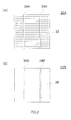
- the crystalline solar module is generally manufactured through, for example, a lamination process in which a protection film for solar cell module (front protective member), an encapsulant sheet for solar cells, crystalline solar cells formed of polycrystalline silicon or mono-crystalline silicon, an encapsulant sheet for solar cells, and another protection film for solar cell module (back protective member) are sequentially stacked and the module is laminated under heating in vacuum condition.
- the thin-film solar cell module is generally manufactured through, for example, a lamination process in which thin-film solar cell prepared by forming a ultra-thin (several micrometers) amorphous silicon or crystalline silicon film onto glass or the like, an encapsulant sheet for solar cells, and a protection film for solar cell module (back protective member) are sequentially stacked and the module is laminated under heating in vacuum condition.
- a lamination process in which thin-film solar cell prepared by forming a ultra-thin (several micrometers) amorphous silicon or crystalline silicon film onto glass or the like, an encapsulant sheet for solar cells, and a protection film for solar cell module (back protective member) are sequentially stacked and the module is laminated under heating in vacuum condition.
- Solar cell modules manufactured in this way are weather-resistant and thus are suitable for use in outdoor environment such as on the roof of a building.
- EVA ethylene-vinyl acetate copolymer
- encapsulant material for solar cells for the requirements for high transparency and high flexibility
- Patent Literature 1 ethylene-vinyl acetate copolymer
- the material is typically subjected to crosslinking to obtain sufficient heat resistance.
- Crosslinking treatment takes a relatively long time (0.2 to 2 hr or so) and thus reduces the production rate or productivity of solar cell modules.
- acetic acid gas and other unwanted gas generated by decomposition of EVA may affect the performance of the photovoltaic devices.
- Patent Literature 2 fails to disclose any specific guide as to physical properties of ethylene/ ⁇ -olefin copolymer for achieving preferable encapsulant material properties (e.g., heat resistance, transparency, flexibility, and process stability).
- encapsulant material properties e.g., heat resistance, transparency, flexibility, and process stability.
- Patent Literature 3 Another disclosed encapsulant material for solar cells contains metallocene linear low-density polyethylene with a specific density range (see Patent Literature 3).
- Patent Literature 3 fails to disclose, except for density, any specific guide as to physical properties for achieving preferable encapsulant material properties.
- a possible reason for this is that the technology disclosed therein presupposes conducting crosslinking treatment and therefore aims to achieve desired physical properties on the condition that crosslinking is conducted.
- the encapsulant material disclosed by Patent Literature 3 has the drawback of possible reduction in heat resistance and humidity resistance.
- An object of the present invention is to establish, in light of the foregoing circumstances, a clear guide for achieving (but not necessarily conducting crosslinking treatment) desired properties of an encapsulant material for solar cells made of an ethylene resin composition. More specifically, an object of the present invention is to provide an ethylene resin composition which has excellent properties including adhesion, electrical insulation properties, transparency, moldability, long-term storage stability, cushioning properties and process stability upon production of an encapsulant material for solar cells and which can eliminate the need for crosslinking where necessary for improved productivity, and an encapsulant material for solar cells. Another object of the present invention is to provide an ethylene resin composition which can achieve high heat resistance, humidity resistance and adhesion at the same time. Still another object of the present invention is to provide a solar cell module manufactured using the ethylene resin composition and encapsulant material for solar cells.
- the inventors conducted extensive studies to overcome the foregoing problems pertinent in the art and as a result developed a new ethylene resin composition containing a modified product which is obtained by modifying ethylene polymer (A) having a specific density range, a specific melting point range, a specific melt flow rate range, a specific molecular weight distribution range and a specific metal residue content range and where necessary ethylene/ ⁇ -olefin copolymer (C), with ethylenically-unsaturated silane compound (B).
- A ethylene polymer having a specific density range, a specific melting point range, a specific melt flow rate range, a specific molecular weight distribution range and a specific metal residue content range and where necessary ethylene/ ⁇ -olefin copolymer (C), with ethylenically-unsaturated silane compound (B).
- the inventors established that the ethylene resin composition can provide an encapsulant material for solar cells which has good adhesion, electrical insulation properties, transparency, moldability and process stability and which can eliminate the need for crosslinking where necessary for improved productivity.
- the inventors also established that the combined use of a modified product of ethylene polymer (A) and a modified product of ethylene/ ⁇ -olefin copolymer (C) may make it possible to attain high heat resistance, high humidity resistance, and high adhesion at the same time.
- the present invention has been accomplished based on these findings.
- a first aspect of the present invention relates to ethylene resin compositions given below.
- a second aspect of the present invention relates to encapsulant materials for solar cells made of the ethylene resin composition, and to solar cell modules manufactured using the encapsulant material.
- the present invention can provide an ethylene resin composition which has good adhesion to glass, a backsheet and a thin-film electrode as well as high electrical insulation properties, transparency, moldability, long-term storage stability, cushioning properties and process stability. And also the ethylene resin composition can eliminate the need for crosslinking where necessary for improved productivity.
- the present invention can also provide an ethylene resin composition which can achieve high heat resistance, humidity resistance and adhesion at the same time, and encapsulant material for solar cells containing the same.
- the encapsulant material for solar cells according to the present invention is useful as encapsulant material for solar cells for thin-film solar cell modules, particular as encapsulant material for solar cells used for the backside of crystalline solar cell modules.
- An ethylene resin composition of the present invention may contain a modified product of ethylene polymer (A) which satisfies the following requirements a) to e) simultaneously, and may further contain a modified product of ethylene- ⁇ -olefin copolymer (C) as needed.
- a modified product of ethylene polymer (A) contained in an ethylene resin composition of the present invention is produced by modifying ethylene polymer (A) with ethylenically-unsaturated silane compound (B) under the presence of organic peroxide.
- a modified product of ethylene/ ⁇ -olefin copolymer (C) contained in an ethylene resin composition of the present invention is produced by modifying ethylene/ ⁇ -olefin copolymer (C) with ethylenically-unsaturated silane compound (B) under the presence of organic peroxide.
- ethylene polymer (A) from which a modified product of ethylene polymer (A) is produced there are no particular limitations on ethylene polymer (A) from which a modified product of ethylene polymer (A) is produced as long as it has an ethylene-derived unit and satisfies the requirements a) to e) described later.
- Ethylene polymer (A) may be, for example, an ethylene homopolymer or a copolymer of ethylene and ⁇ -olefin or cyclic olefin.
- the ⁇ -olefin in the ethylenc/ ⁇ -olefin copolymer may be a C 3-20 ⁇ -olefin.
- Examples of C 3-20 ⁇ -olefins include propylene, 1-butene, 1-pentene, 1-hexene, 4-methyl-l-pentene, 1-octene, 1-decene, 1-dodecene, 1-tetradecene, 1-hexadecene, 1-octadecene, and 1-eicosene.
- C 4-10 ⁇ -olefins are preferable, with 1-butene, 1-hexene, and 1-octene being most preferable.
- cyclic olefins used for the copolymer of ethylene and cyclic olefin include norbornene derivatives, tricyclo-3-decene derivatives, tricyclo-3-undecene derivatives, tetracyclo-3-dodecene derivatives, pentacyclo-4-pentadecene derivatives, pentacyclo-pentadecadiene derivatives, pentacyclo-3-pcntadecene derivatives, pentacyclo-4-hexadecene derivatives, pentacyclo-3-hexadecene derivatives, hexacyclo-4-heptadecene derivatives, heptacyclo-5-eicosene derivatives, heptacyclo-4-eicosene derivatives, heptacyclo-5-heneicosene derivatives, octacyclo-5-docosene derivatives, nonacyclo-5
- ⁇ -olefins and cyclic olefins may be used alone or in combination. These ⁇ -olefins and cyclic olefins may form either random copolymers or block copolymers with ethylene.
- Ethylene polymer (A) used for the ethylene resin composition of the present invention satisfies the requirements a) to e) given below.
- Ethylene polymer (A) has a density of 900 to 940 kg/m 3 .
- Ethylene polymer (A) preferably has a density of 900 to 935 kg/m 3 , more preferably 900 to 930 kg/m 3 , further preferably 900 to 925 kg/m 3 , still further preferably 905 to 925 kg/m 3 , most preferably 905 to 923 kg/m 3 .
- the resultant encapsulant material has low heat resistance.
- the encapsulant material in a solar cell module softens, and therefore glass, electrodes and other components gradually slip and fall down when the solar cell module is held inclined during photovoltaic power generation.
- sheet blocking occurs, which hinders unrolling of a sheet roll, and that the chill roll and embossing roll become so sticky that controlling of sheet thickness and sheet molding becomes difficult.
- the encapsulant material When ethylene polyemer (A) has a density of greater than 940 kg/m 3 , the encapsulant material has less flexibility, which causes cracking of silicon crystal cells and/or separation of the silver elecrode during the lamination process of a solar cell module. Moreover, in this case, since the encapsulant material is hard to melt, the temperature during the lamination process needs to be set higher than 150°C, a general laminator temperature. If being the general laminator temperature of 150°C, the first step (heating by residual heat in vacuum condition) needs to be carried out for a long time.
- the density of ethylene polymer (A) depends on the comonomer content, such as ⁇ -olefin content. Specifically, the density increases with decreasing comonomer content in ethylene polymer (A) and vice versa.
- the comonomer content in ethylene polymer (A) is known to be determined by the comonomer/ethylene ratio in the polymerization system (see, e.g., Walter Kaminsky, Makromol. Chem. 193, p.606 (1992)).
- the density of ethylene polymer (A) can be adjusted by adjusting the comonomer/ethylene ratio.
- the density of ethylene polymer (A) can be measured with a density gradient tube method.
- the peak melt temperature of ethylene polymer (A) as measured by DSC is 90°C to 125°C, preferably 90°C to 120°C, more preferably 90°C to 115°C.
- the resultant encapsulant material has low heat resistance.
- the encapsulant material in a solar cell module softens, and therefore glass and electrodes gradually slip and fall down when the solar cell module is held inclined during photovoltaic power generation.
- sheet blocks occurs, which makes unrolling difficult, and that the chill roll and embossing roll become so sticky so that controlling of sheet thickness and sheet molding becomes difficult.
- ethylene polymer (A) has a peak melt temperature of greater than 125°C, the encapsulant material has less flexibility, which causes cracking of silicon crystal cells and/or separation of the silver electrode during the lamination process of the solar cell module.
- the temperature during the lamination process needs to be set higher than 150°C, a general laminator temperature. If being the general laminator temperature of 150°C, the first step (heating by residual heat in vacuum condition) needs to be carried out for a long time.
- the peak melt temperature of ethylene polymer (A) depends on the comonomer content, such as ⁇ -olefin content. Specifically, the peak melt temperature increases with decreasing comonomer content in ethylene polymer (A) and vice versa.
- the comonomer content in ethylene polymer (A) is known to be determined by the comonomer/ethylene ratio in the polymerization system (see, e.g., Walter Kaminsky, Makromol. Chem. 193, p.606 (1992)).
- the peak melt temperature of ethylene polymer (A) can be adjusted by adjusting the comonomer/ethylene ratio.
- the peak melt temperature of ethylene polymer (A) can be measured with DSC through the following DSC procedure:
- Ethylene polymer (A) has a melt flow rate (MFR2) of 1 to 100 g/10min, preferably 0.5 to 50 g/10min, more preferably 0.5 to 20 g/10min, as measured in accordance with JIS K-6721 at 190°C under a load of 2.16 kg.
- MFR2 melt flow rate
- melt flow rate (MFR2) melt flow rate of less than 0.1 g/10min
- MFR2 melt flow rate of greater than 100 g/10min
- the ethylene resin composition becomes so flowable that sheet molding becomes difficult, and moreover, the sheet has poor mechanical properties, such as poor tensile strength.
- the melt flow rate (MFR2) of ethylene polymer (A) largely depends on the molecular weight of ethylene polymer (A). Specifically, there is tendency that the molecular weight of ethylene polymer (A) increases with decreasing melt flow rate (MFR2) and vice versa.
- the molecular weight of ethylene polymer (A) is known to be determined by the hydrogen/ethylene ratio in the polymerizetion system (see, e.g., Kazuo Soga, KODANSHA "CATALYTIC OLEFIN POLYMERIZATION" p.376 (1990 )). Thus, by adjusting the hydrogen/ethylene ratio, it is possible to produce ethylene polymer (A) that satisfies the requirement (c) specified in the present invention.
- melt flow rate (MFR2) of ethylene polymer (A) can be measured in accordance with JIS K-6721 at 190°C under a load of 2.16 kg.
- the ratio of weight-average molecular weight (Mw) to number-average molecular weight (Mn) of ethylene polymer (A), Mw/Mn ratio, in an ethylene resin composition of the present invention as measured by gel permeation chromatography (GPC) is 1.2 to 3.5, preferably 1.2 to 3.2, more preferably 1.2 to 2.8.
- the ratio of weight-average molecular weight (Mw) to number-average molecular weight (Mn), Mw/Mn ratio is generally influenced by the composition distribution.
- Mw/Mn ratio tends to be small at a low comonomer conversion, and tends to be high at a high comonomer conversion.
- the term "comonomer conversion” refers to the ratio of the comonomer participating in the polymerization reaction to the comonomer charged. By shortening the polymerization time, the comonomer conversion becomes small, whereby degradation of the active species of polymerization catalyst can be suppressed.
- the composition distribution becomes narrow, and therefore the Mw/Mn ratio tends to become small.
- the comonomer conversion becomes high so that degradation of the polymerization catalyst occurs. Accordingly, the composition distribution becomes broad, and therefore the Mw/Mn ratio tends to become large.
- the mean residence time is prolonged, deterioration of the active species of polymerization catalyst occurs and therefore the composition distribution becomes broad, whereby the Mw/Mn ratio tends to become large.
- the molecular weight distribution (Mw/Mn) of ethylene polymer (A) can be measured by GPC on Waters Alliance GPC 2000.
- the metal residue content in ethylene polymer (A) is 0.1 to 50 ppm, preferably 0.1 to 45 ppm, further preferably 0.1 to 40 ppm, most preferably 5 to 50 ppm.
- ethylene polymer (A) When the metal residue content in ethylene polymer (A) is less than 0.1 ppm, decalcification of polymerization catalyst is indispensable, which increases plant's fixed costs as well as serve costs leading to increased production costs. Moreover, since a large quantity of acid or base or chelating agent is required for decalcification, it becomes likely that the acid or base or chelating agent remains in ethylene polymer (A). For this reason, when ethylene polymer (A) is used as a raw material of encapsulant material for solar cells, such an acid, base or chelating agent remaining in ethylene polymer (A) may corrode the electrode or other member of a solar cell module. When the metal residue content is less than 0.1 ppm, on the other hand, it results in low long-term storage stability.
- metal residues serve as an agent for capturing an acid and alkali. Specifically, it is conjectured that when metal residues are scarce, substances responsible for breaking bonds between glass and resin cannot be fully shut out, and therefore, bond breakage often occurs.
- Ti Zr, Hf and the like - which are metals generally used in metallocene compounds used as a polymerization catalyst of ethylene polymer (A) - are present in small amount, they activate organic peroxide and thereby increases the grafting efficiency of ethylenically-unsaturated silane compound (B) during the extrusion modification process.
- metal residues in ethylene polymer (A) when the metal residue content in ethylene polymer (A) is greater than 50 ppm, metal residues reduce volume resistivity and dielectric breakdown strength. Moreover, when the metal residue content in ethylene polymer (A) is greater than 50 ppm, it results in low long-term storage stability. This is considered to be due to the fact that when ethylene polymer (A) is used as a raw material of encapsulant material for solar cells, metal ions leach into the contact surface between a glass and a encapsulant material of solar cells and break bonds between the glass and the encapsulant material.
- the metal residue is derived from, for example, a transition metal of a metallocene compound, which serves as an active species of polymerization catalyst.
- the quantity of the metal residue depends on the polymerization activity. Specifically, when a polymerization catalyst with a high polymerization activity is used, the amount of catalyst with respect to monomer, and therefore the metal residue content, can be reduced. Thus, the use of a polymerization catalyst with a high polymerization activity is a suitable approach to reduce the metal residue content.
- Other suitable approaches to reduce the residual metal content by increasing polymerization activity include conducting polymerization at a polymerization temperature optimal for a polymerization catalyst used, and increasing the monomer concentration per unit polymerization catalyst by increasing the polymerization pressure as much as possible.
- an organic aluminumoxy compound, a compound that forms ion pairs by reaction with the metallocene compound, an organic aluminum compound or the like is added to the metallocene compound. Reducing the added amount of these compounds as much as possible is also a suitable approach to reduce the metal residue content.
- increasing polymerization activity in different ways may also be a suitable approach to reduce the metal residue content.
- the metal residue content may be reduced with decalcification by using an acid, an alkali, or a chelating agent such as methyl acetoacetate.
- this decalcification is not suitable for the present invention because when the acid and alkali or chelating agent remains in ethylene polymer (A), they facilitate corrosion of the thin-film electrodes.
- the metal residue content in ethylene polymer (A) can be measured through the following procedure:
- Ethylene polymer (A) used in the present invention can be produced using an ethylene polymerization catalyst component known in the art.
- ethylene polymerization catalyst component known in the art.
- Ziegler-Natta catalysts or metallocene compounds can be used.
- metallocene compounds which have a high polymerization activity per unit transition metal, are preferable because ethylene polymer (A) with less metal residues can be obtained without having to perform decalcification treatment.
- Metallocene compounds those described in JP-A Nos.2006-077261 . 2008-231265 and 2005-314650 can be used, for example.
- Metallocene compounds which have different structure than those of the metallocene compounds dislcosed in the above Patent Literature can also be used as long as ethylene polymer (A) that satisfies the requirements a) to e) can be obtained. Two or more different metallocene compounds may be blended.
- a preferable embodiment of a process for producing ethylene polymer (A) using a metallocene compound is, for example, a process in which ethylene is homopolymerized, ethylene and at least one C 3-20 ⁇ -olefin are copolymerized, or ethylene and a cyclic olefin are copolymerized, under the presence of an olefin polymerization catalyst consisting of a metallocene compound (I) known in the art and at least one compound (II) (referred to as a "catalytic promoter" in some cases) selected from the group consisting of an organic aluminumoxy compound (II-1) , a compound that forms ion pairs by reaction with the metallocene compound (11-2), and an organic aluminum compound (11-3).
- an olefin polymerization catalyst consisting of a metallocene compound (I) known in the art and at least one compound (II) (referred to as a "catalytic promoter" in some cases) selected from the group consisting
- organic aluminumoxy compound (II-1), compound (II-2) that forms ion pairs by reaction with the Metallocene compound and organic aluminum compound (II-3), those described in JP-A Nos.2006-077261 , 2008-231265 and 2005-314680 can be used. Any compound that differs from those described in these Patent Literatures can be used as long as ethylene polymer (A) that satisfies the above requirements a) to e) can be obtained. These compounds may be individually charged into a polymerization atmosphere or may be previously contacted with one another before being charged into the polymerization atmosphere. The above metallocene compounds and promoters may be loaded on an inorganic oxide microparticle carrier such as that described in JP-A No.2005-314680 .
- Ethylene polymer (A) can be produced by gas-phase polymerization known in the art or by liquid-phase polymerization such as slurry polymerization or solution polymerization.
- Polymerization is preferably gas-phase polymerization or slurry polymerization, a polymerization process where polymerization activity is high and less metal residue is produced.
- Slurry polymerization and solution polymerization are carried out under the presence of an non-reactive carbohydrate medium, such as an aliphatic hydrocarbon such as propane, butane, pentane, hexane, heptane, octane, decane, dodecane, and kerosene; an alicyclic hydrocarbon such as cyclopentane, cyclohexane, and methylcyclopentane; an aromatic hydrocarbon such as benzene, toluene, and xylene; a halogenated hydrocarbon such as ethylenechloride, chlorobenzene, and dichloromethane; or a mixture thereof.
- an aliphatic hydrocarbon such as propane, butane, pentane, hexane, heptane, octane, decane, dodecane, and kerosene
- an alicyclic hydrocarbon such as cyclopentane, cyclohex
- the metallocene compound (I) is used in an amount of 10 -9 to 10 -1 mol, preferably 10 -8 to 10 -2 mol, per 1L reaction volume.
- the amount of the metallocene compound (I) is less than 10 -9 mol/L, the polymerization reaction takes place less frequently resulting in unwanted reduction in polymerization activity.
- the compound (II-1) is used in an amount such that the mole ratio of the compound (II-1) to total metal atoms (M) in metallocene compound (I), [(II-1)/M], ranges from 1 to 10,000, more preferably 1 to 5,000.
- the compound (II-2) is used in an amount such that the mole ratio of the compound (II-2) to total metal atoms (M) in metallocene compound (1), [(II-2)/M], ranges from 0.5 to 50, more preferably I to 20.
- the compound (II-3) is used in an amount of 0 to 5 mmol, preferably about 0 to 2 mmol, per 1L polymerization reaction volume.
- polymerization temperature is 0°C to 200°C, 20°C to 190°C, more preferably 40°C to 180°C.
- polymerization temperature of less than 0°C is not practical in terms of productivity, because at such a temperature level polymerization activity remarkably drops.
- solution's viscosity during polymerization decreases with increasing temperature, and removal of polymerization heat is facilitated.
- the polymerization temperature exceeds 200°C, it results in remarkable reduction in polymerization activity, and therefore, the polymerization process becomes less practical in terms of productivity.
- Polymerization pressure is from normal pressure to 10 MPa (gauge pressure), preferably from normal pressure to 8 MPa (gauge pressure).
- Polymerization can be carried out in a batchwise, semi-continuous or continuous process.
- Reaction time (average residence time in cases where polymerization is carried out in a continuous process) varies depending on the reaction condition such as catalyst concentration or polymerization temperature, and can be determined according to the intended purpose; reaction time is 1 minute to 3 hours, preferably 10 minutes to 2.5 hours.
- Polymerization can also be carried out in two or more stages of different reaction conditions.
- the molecular weight of ethylene polymer (A) to be produced can also be adjusted by changing the hydrogen concentration in the polymerization system and/or polymerization temperature within the scope of the present invention.
- the molecular weight of ethylene polymer (A) can be adjusted by changing the amount of the compound (II) used.
- an appropriate added amount is about 0.001NL to about 5,OOONL per 1Kg of ethylene/ ⁇ -olefin copolymer.
- ethylene polymer (A) produced by the above polymerization process is subjected to decalcification treatment known in the art used for the production of olefin polymer, for removal of catalyst components and inorganic oxide microparticle carrier.
- ethylenically-unsaturated silane compound (B) used in the present invention there are no particular limitations on ethylenically-unsaturated silane compound (B) used in the present invention; known ethylenically-unsaturated silane compounds can be used. Specific examples include vinyltriethoxysilane, vinyltrimetoxysilane, vinyltris( ⁇ -methoxy-ethoxysilane), ⁇ -glycidoxypropyl-trimethoxysilane, ⁇ -aminopropyltriethoxy silane, ⁇ -methacryloxpropyltrimethoxy silane, 2-(3,4-epoxycyclohexyl)ethyltrimethoxysilane, 3-glycidoxypropyltrimetoxysilane, 3-glycidoxypropylmethylethoxysilane, p-styryltrimethoxysilane, 3-methacryloxypropylmethyldimethoxysilane, 3-
- ⁇ -glycidoxypropyltrimetoxysilane, ⁇ -aminopropyltriethoxysilane, ⁇ -methacryloxpropyltrimethoxysilane, vinyltriethoxysilane, vinyltrimetoxysilane, 3-acryloxypropyltrimethoxysilane, etc. which provide the ethylene resin composition with high adhesion, are preferred.
- Vinyltriethoxysilane, vinyltrimetoxysilane, and 3-acryloxypropyltrimethoxysilane are more preferable. This is because the resultant ethylene resin composition has good adhesion and thus can shorten the time in which the module is laminated, and that they have less steric hindrance and therefore the grafting efficiency of ethylene polymer (A) is high.
- the compounding amount of ethylenically-unsaturated silane compound (B) is 0.1 to 5 weight parts, preferably 0.1 to 4 weight parts, more preferably 0.3 to 4 weight parts, further preferably 0.3 to 2.5 weight parts, most preferably 0.5 to 2.5 weight parts, per 100 weight parts of ethylene polymer (A) or 100 weight parts of the total amount of ethylene polymer (A) and ethylene/ ⁇ -olefin copolymer (C) later described.
- Ethylene/ ⁇ -olefin copolymer (C) from which a modified product of ethylene/ ⁇ -olefin copolymer (C) is produced can be prepared by copolymerizaton of ethylene and one or more different C 3-20 ⁇ -olefins.
- C 3-20 ⁇ -olefins include straight- or branched-chain ⁇ -olefins, such as, propylene, 1-butene, 2-bntene, 1-pentene, 3-methyl-1-butene, 1-hexane, 4-methyl-1-pentene, 3-methyl-1-pentene, 1-octene, 1-decene, and 1-dodecene.
- ⁇ -olefins usable in the present invention include polar group-containing olefins.
- polar group-containing olefins examples include ⁇ , ⁇ -unsaturated carboxylic acids such as acrylic acid, methacrylic acid, fumaric acid and maleic anhydride, and metal salts (e.g., sodium salts) thereof; ⁇ , ⁇ -unsaturated carboxylic acid esters such as methyl acrylate, ethyl acrylate, n-propyl acrylate, methyl methacrylate, and ethyl methacrylate; vinyl esters such as vinyl acetate, and vinyl propionate; and unsaturated glycidyls such as metaglycidyl acrylate and glycidyl methacrylate.
- carboxylic acids such as acrylic acid, methacrylic acid, fumaric acid and maleic anhydride, and metal salts (e.g., sodium salts) thereof
- ⁇ , ⁇ -unsaturated carboxylic acid esters such as methyl acrylate, ethyl acrylate, n-
- Polymerization can also be carried out under the coexistence of vinylcyclohexane, diene or polyene; an aromatic vinyl compound such as styrene, including o-methylstyrene, m-methylstyrene, p-methylstyrene, o,p-dimethylstyrene, methoxy styrene, and vinylbenzoic acid, vinylmethyl benzoate or vinylbenzyl acetate, hydroxystyrene, p-chlorostyrene, or divinylbenzene; or 3-phenylpropylene, 4-phenylpropylene or ⁇ -methylstyrene.
- an aromatic vinyl compound such as styrene, including o-methylstyrene, m-methylstyrene, p-methylstyrene, o,p-dimethylstyrene, methoxy styrene, and vinylbenzoic acid, vinylmethyl benzoate or
- the C 3-20 ⁇ -olefins are preferably ⁇ -olefins having 4 or more carbon atoms. Most preferable are C 4-8 ⁇ -olefins.
- Examples of such ⁇ -olefins include 1-butene, 1-pentene, 1-hexene, 3-methyl-1-butene, 3,3-dimethyl-1-butene, 4-methyl-1-pentene, and 1-octene, and can be used alone or in combination.
- 1-butene, 1-pentene, 1-hexene, 4-methyl-1-pentene, and 1-octane are preferable in view of their availability and physical properties of a copolymer to be produced.
- C 3-20 cyclic olefins such as cyclopentene, cycloheptene, norbornene, 5-methyl-2-norbornene, 5-ethylidene-2-norbornene, and 5-vinyl-2-norbornene may be used in combination.
- the comonomer in ethylene polymer (A) is not identical to the comonomer in ethylene/ ⁇ -olefin copolymer (C). This is because when the two comonomers are identical, the compatibility between ethylene polymer (A) and ethylene/ ⁇ -olefin copolymer (C) increases, and therefore the resultant ethylene resin composition tends to have low heat resistance. It should be noted, however, that the comonomer in ethylene polymer (A) may be identical to the comonomer in ethylene/ ⁇ -olefin copolymer (C) as long as the resultant ethylene resin composition has satisfactory heat resistance. Ethylene/ ⁇ -olefin copolymer (C) may be either a random copolymer or a block copolymer.
- the ⁇ -olefin-derived unit content in ethylene/ ⁇ -olefin copolymer (C) is 9 to 22 mol%, preferably 10 to 22 mol%, more preferably 11 to 17 mol%.
- the ⁇ -olefin-derived unit content in ethylene/ ⁇ -olefin copolymer (C) is less than 9 mol%, there is tendency that tackiness cannot be increased, failing to increase adhesion.
- ⁇ -olefin-derived unit content in ethylene/ ⁇ -olefin copolymer (C) is greater than 22mol%, the compatibility of ethylene/ ⁇ -olefin copolymer (C) with ethylene polymer (A) decreases, and therefore bleed out occurs on the sheet surface, which makes unrolling of a rolled sheet difficult. Moreover, the chill roll and embossing roll become sticky during sheet molding, so that controlling of sheet thickness and sheet molding may become difficult.
- Ethylene/ ⁇ -olefin copolymer (C) has a density of 850 to less than 893 kg/m 3 , preferably 850 to 890 kg/m 3 , more preferably 850 to 880 kg/m 3 .
- density of ethylene/ ⁇ -olefin copolymer (C) is greater than 895 kg/m 3 . tackiness and, therefore, adhesion cannot be increased, and no flexibility is imparted.
- the density of ethylene/ ⁇ -olefin copolymer (C) is less than 850 kg/m 3 , its compatibility with ethylene polymer (A) decreases, and therefore bleed out occurs on the sheet surface, which makes unrolling of a rolled sheet difficult.
- the chill roll and embossing roll become sticky during sheet molding, so that controlling of sheet thickness and sheet molding may also become difficult.
- the net result of the above is that when the density of ethylene/ ⁇ -olefin copolymer (C) is set to 850 kg/m 3 to less than 895 kg/m 3 , ethylene/ ⁇ -olefin copolymer (C) is less compatible with ethylene polymer (A), and therefore, heat resistance of the resultant ethylene resin composition can be ensured without causing reduction in the crystallinity of ethylene polymer (A).
- controlling of sheet thickness and sheet molding are made possible without causing difficulty in unrolling sheet rolls or making the chill roll and embossimg roll sticky during sheet molding.
- the peak melt temperature of ethylene/ ⁇ -olefin copolymer (C) as measured by DSC is 85°C or less or in a substantially unmeasurable range, preferably 80°C or less or in a substantially unmeasurable range, more preferably 75°C or less or in a substantially unmeasurable range.
- the peak melt temperature of ethylene/ ⁇ -olefin copolymer (C) is greater than 85°C, there is tendency that tackiness as well as adhesion does not increase.
- the melt flow rate (MFR2) of ethylene/ ⁇ -olefin copolymer (C), as measured in accordance with JIS K-6721 at 190°C under a load of 2.16 kg, is 0.1 to 100 g/10min, preferably 0.1 to 80 g/10min, more preferably 0.5 to 80 g/10min, further preferably 1.0 to 50 g/10min.
- melt flow rate (MFR2) of ethylene/ ⁇ -olefin copolymer (C) is less than 0.1 g/10min, an ethylene resin composition containing ethylene/ ⁇ -olefin copolymer (C) becomes less flowable, resulting in low sheet molding productivity.
- scorch of the resin composition becomes more likely to take place ("scorch” means premature crosslinking of a resin composition during processing), thus facilitating gelletion. This may increase the extruder' torque, which makes difficult sheet molding. Even when a sheet is obtained, gels generated in the extruder may create irregularities on the sheet surface which deteriorate appearance. Moreover, application of voltage cause cracks around gels inside the sheet, reducing dielectric breakdown strength.
- the ratio of MFR10 (melt flow rate as measured in accordance with JIS K-6721 at 190°C under a load of 10kg) to MFR2 of ethylene/ ⁇ -olefin copolymer (C), MFR10/MFR2, is 5.0 to 8.0.
- the MFR10/MFR2 ratio is preferably 5.5 to 8.0, more preferably 5.5 to 7.5.
- the MFR10/MFR2 ratio is less than 5.0, production of ethylene/ ⁇ -olefin copolymer (C) becomes difficult.
- the MFR10/MFR2 ratio is greater than 8.0, there is tendency that the resin composition has poor low-temperature characteristics.
- the ratio of weight-average molecular weight (Mw) to number-average molecular weight (Mn) of ethylene/ ⁇ -olefin copolymer (C) as measured by gel permeation chromatography (GPC), i.e., molecular weight distribution Mw/Mn, is 1.2 to 3.5, preferably 1.5 to 3.5, more preferably 1.7 to 3.2.
- GPC gel permeation chromatography
- ethylene/ ⁇ -olefin copolymer prepared with a conventional polymerization process with a low catalytic activity has to be purified for removing both of low-molecular weight oligomers and high-molecular weight oligomers, which increases production costs.
- a moldable temperature range becomes narrow and since the discharge amount from an extruder becomes non-uniform, it becomes difficult to produce a uniform thick sheet.
- the Mw/Mn ratio of ethylene/ ⁇ -olefin copolymer (C) is greater than 3.5, low-molecular oligomers occur.
- the compounding amount of ethylene/ ⁇ -olefin copolymer (C) is such that the ratio of ethylene polymer (A) to ethylene/ ⁇ -olefin copolymer (C) is 100/0 to 10/90 (weight ratio), preferably 100/0 to 20/80 (weight ratio), more preferably 100/0 to 40/60 (weight ratio), still more preferably 100/0 to 60/40 (weight ratio).
- the resultant encapsulant material has low heat resistance. For this reason, when a solar cell module is held inclined during photovoltaic power generation, there is tendency that glass, electrodes and other components gradually slip and fall down, and that the chill roll and embossing roll become so sticky that controlling of sheet thickness and sheet molding becomes difficult. Moreover, sheet blocking occurs, which makes unrolling of a rolled sheet difficult.
- the resultant ethylene resin composition has improved tackiness, and therefore, the encapsulant material tends to have improved adhesion to adherends, the adherends are typically back protective components for solar cell modules, such as polyester plates, steel plates, plastic plates, and FRP plates.
- ethylene/ ⁇ -olefin copolymer (C) can be produced using a variety of catalysts, such as titanium compounds, vanadium compounds, or metallocene compounds. It is preferable to employ metallocene compounds with which an ethylene/ ⁇ -olefin copolymer having a Mw/Mn ratio and composition distribution that satisfies the above-described conditions can be readily obtained.
- metallocene compounds those described in JP-A Nos.2006-077261 , 2008-231265 and 2005-314680 can be used, for example.
- Metallocene compounds which have different structure than those of the metallocene compounds disclosed in the above Patent Literature can also be used as long as ethylene polymer (A) that satisfies the requirements a) to e) can be obtained. Two or more different metallocene compounds may be combined.
- a preferable embodiment of a process for producing ethylene/ ⁇ -olefin copolymer (C) is, for example, a process in which ethylene is copolymerized with one or more C 3-20 ⁇ -olefins under the presence of an olefin polymerization catalyst consisting of a metallocene compound (I) known in the art and at least one compound (II) selected from the group consisting of an organic aluminumoxy compound (II-1), a compound (II-2) that forms ion pairs by reaction with the Metallocene compound, and an organic aluminum compound (II-3) (referred to as a "promoter" in some cases).
- an olefin polymerization catalyst consisting of a metallocene compound (I) known in the art and at least one compound (II) selected from the group consisting of an organic aluminumoxy compound (II-1), a compound (II-2) that forms ion pairs by reaction with the Metallocene compound, and an organic aluminum compound (II-3)
- organic aluminumoxy compound (II-1), compound (II-2) that forms ion pairs by reaction with the metallocene compound and organic aluminum compound (II-3), those for the production of ethylene polymer (A) described above can be used.
- the above metallocene compounds and promoters may be loaded on an inorganic oxide microparticle carrier such as that described in JP-A No.2005-314680 .
- Ethylene/ ⁇ -olefin copolymer (C) can be produced by conventional gas-phase polymerization or by conventional liquid-phase polymerization such as slurry polymerization or solution polymerization.
- Ethylene/ ⁇ -olefin copolymer (C) is preferably produced by liquid-phase polymerization such as solution polymerization.
- the metallocene compound (I) is used in an amount of 10 -9 to 10 -1 mol, preferably 10 -8 to 10 -2 mol, per 1L reaction volume.
- the compound (II-I) is used in an amount such that the mole ratio of the compound (II-1) to total metal atoms (M) in metallocene compound (I), [(II-1)/M], is 1 to 10,000, more preferably 1 to 5,000.
- the compound (II-2) is used in an amount such that the mole ratio of the compound (II-2) to total metal atoms (M) in metallocene compound (I), [(II-2)/M], is 0.5 to 50, more preferably 1 to 20.
- the compound (II-3) is used in an amount of 0 to 5 mmol, preferably 0 to 2 mmol, per 1L polymerization reaction volume.
- ethylene/ ⁇ -olefin copolymer (C) with high comonomer content a narrow composition distribution and a narrow molecular weight distribution can be efficiently produced by copolymerization of ethylene with a C 3-20 ⁇ -olefin under the presence of the above metallocene compound.
- the charging ratio of ethylene to C 3-20 ⁇ -olefin (by mole) ethylene/ ⁇ -olefin is 10/90 to 99.9/0.1, preferably 30/70 to 99.9/0.1, more preferably 50/50 to 99.9/0.1.
- C 3-20 ⁇ -olefins include straight- or branched-chain ⁇ -olefins, such as, propylene, 1-butene, 2-butene, 1-pentene, 3-methyl-1-butene, 1-hexene, 4-rnethyl-1-pentezae, 3-methyl-1-pentene, 1-octene, 1-decene, and 1-dodecene.
- ⁇ -olefins usable in the present invention include polar group-containing olefins.
- polar group-containing olefins examples include ⁇ , ⁇ -unsaturated carboxylic acids such as acrylic acid, methacrylic acid, fumaric acid and maleic anhydride, and metal salts (e.g., sodium salts) thereof; ⁇ , ⁇ -unsaturated carboxylic acid esters such as methyl acrylate, ethyl acrylate, n-propyl acrylate, methyl methacrylate, and ethyl methacrylate; vinyl esters such as vinyl acetate, and vinyl propionate; and unsaturated glycidyls such as metaglycidyl acrylate and glycidyl methacrylate.
- carboxylic acids such as acrylic acid, methacrylic acid, fumaric acid and maleic anhydride, and metal salts (e.g., sodium salts) thereof
- ⁇ , ⁇ -unsaturated carboxylic acid esters such as methyl acrylate, ethyl acrylate, n-
- High-temperature solution polymerization can also be proceeded under the coexistence of vinylcyclohexane, diene or polyene; an aromatic vinyl compound such as styrene derivatives, styrene, o-methylstyrene, m-methylstyrene, p-methylstyrene, o,p-dimethylstyrene, methoxy styrene, vinylbenzoic acid, vinylmethyl benzoate, vinylbenzyl acetate, hydroxystyrene, p-chlorostyrene, or divinylbenzene, 3-phenylpropylene, 4-phenylpropylene or ⁇ -methylstyrene.
- an aromatic vinyl compound such as styrene derivatives, styrene, o-methylstyrene, m-methylstyrene, p-methylstyrene, o,p-dimethylstyrene, methoxy
- ⁇ -olefins 1-butene, 1-hexene, 4-methyl-1-pentene, and 1-octene are preferred.
- C 3-20 cyclic olefins such as cyclopentene, cycloheptene, norbornene, 5-methyl-2-norbornene, 5-ethylidene-2-norbornene, and 5-vinyl-2-norbornene may be used in combination.
- Solution polymerization is a generic term used to refer to a method of polymerization in which a monomer is dissolved in a non-reactive carbohydrate solvent later described.
- Polymerization temperature of the solution polymerization according to the present invention is 0°C to 200°C, preferably 20°C to 190°C, more preferably 40°C to 180°C.
- polymerization temperature of less than 0°C is not practical in terms of productivity, because at such a temperature level not only polymerization activity remarkably drops, but also the number of double bonds at the terminal of molecules of ethylene/ ⁇ -olefin copolymer (C) decreases.
- the polymerization temperature region of 0°C or higher solution's viscosity during polymerization decreases with increasing temperature, and removal of polymerization heat is facilitated.
- the number of double bonds at the terminal of molecules of ethylene/ ⁇ -olefin copolymer (C) increases.
- the polymerization temperature exceeds 200°C it results in remarkable reduction in polymerization activity, and therefore, the polymerization process becomes less practical in terms of productivity.
- Polymerization pressure is from normal pressure to 10 MPa (gauge pressure), preferably from normal pressure to 8 MPa (gauge pressure). Polymerization can be carried out in a batchwise, semi-continuous or continuous process. Reaction time (average residence time in cases where polymerization is carried out in a continuous process) varies depending on the reaction condition such as catalyst concentration or polymerization temperature, and can be determined according to the intended purpose; reaction time is 1 minute to 3 hours, preferably 10 minutes to 2.5 hours. Polymerization can also be carried out in two or more stages with different reaction conditions.
- the molecular weight of ethylene/ ⁇ -olefin copolymer (C) to be produced can also be adjusted by changing the hydrogen concentration in the polymerization system and/or polymerization temperature within the scope of the present invention. Further, the molecular weight of ethylene/ ⁇ -olefin copolymer (C) can be adjusted by changing the amount of the compound (II) used. When hydrogen is to be added, an appropriate added amount is about 0.001 to about 5.000NL per 1Kg of ethylene/ ⁇ -olefin copolymer (C) to be produced.
- the number of vinyl and vinylidene groups present at the terminal of molecules of ethylene/ ⁇ -olefin copolymer (C) to be produced can be adjusted by increasing polymerization temperature or reducing the added amount of hydrogen as much as possible.
- long-chain branches in ethylene/ ⁇ -olefin copolymer (C) can be generated through re-insertion of vinyl-terminated chain molecule as "macromonomer" into the ethylene/ ⁇ -olefin copolymer chain, the macro-monomer being produced by the ⁇ -hydrogen elimination reaction during polymerization.
- macromonomer concentration [macromonomer]/[ethylene]
- MFR10/MFR2 ratio of ethylene/ ⁇ -olefin copolymer (C) it is possible to control the MFR10/MFR2 ratio of ethylene/ ⁇ -olefin copolymer (C).
- the number of long-chain branches in an ethylene/ ⁇ -olefin copolymer increases with increasing [macromonomer]/[ethylene] ratio, and vise versa.
- the relative macromonomer concentration decreases, so that the [macromonomer]/[ethylene] ratio becomes small; consequently, the MFR10/MFR2 ratio of the ethylene/ ⁇ -olefin copolymer decreases.
- chain transfer to A1 atoms may be increased or reduced to change the MFR10/MFR2 ratio of the ethylene/ ⁇ -olefin copolymer.
- Solvents used for solution polymerization according to the present invention are generally non-reactive hydrocarbon solvents, preferably saturated hydrocarbons with boiling points of 50°C to 200°C under normal pressure. Specific examples include alicyclic hydrocarbons such as pentane, hexane, heptane, octane, decane, dodecane, and kerosene; and aliphatic hydrocarbons such as cyclopentane, cyclohexane, and methylcyclopentane.
- aromatic hydrocarbons such as benzene, toluene, and xylene; and halogenated hydrocarbons such as ethylenechloride, chlorobenzene, and dichloromethane are also included in "non-reaction hydrocarbon solvents" used for high-temperature solution polymerization according to the present invention; there is no limitation on the use thereof.
- non-reaction hydrocarbon solvents used for high-temperature solution polymerization according to the present invention
- the solution polymerization process according to the present invention can reduce environmental loads as well as minimize possible adverse effects on the human body.
- ethylene/ ⁇ -olefin copolymer (C) produced by polymerization and other optional additives are preferably melted, kneaded and granulated with any desired method.
- the total density of the resin component after blending ethylene polymer (A) with ethylene/ ⁇ -olefin copolymer (C) is preferably 855 to 940 kg/m 3 , more preferably 870 to 940 kg/m 3 , further preferably 870 to 930 kg/m 3 , most preferably 880 to 920 kg/m 3 .
- the total density of the resin component after blending ethylene polymer (A) with ethylene/ ⁇ -olefin copolymer (C) is less than 855 kg/m 3 , there is tendency that the chill roll and emboss roll become sticky during sheet molding, making controlling of sheet thickness and sheet molding difficult. Moreover, there is tendency that blocking of the sheet occurs, which hinders unrolling of the sheet roll.
- the resultant encapsulant material becomes less flexible and thus it becomes likely that cracking of crystalline cells and/or separation of the silver electrode occur. Moreover, there is a need to increase the temperature during the lamination process.
- Organic peroxides used in the present invention serve as a radical initiator when ethylene polymer (A) and where necessary ethylene/ ⁇ -olefin copolymer (C) are to be graft-modified with ethylenically-unsaturated silane compound (B).
- silane-modified product can provide strong adhesion.
- organic peroxides suitably used in the present invention as long as they are capable of graft-modifying ethylene polymer (A) or ethylene/ ⁇ -olefin copolymer (C) with ethylenically-unsaturated silane compound (B).
- preferable organic peroxides include dilauroyl peroxide, 1,1,3,3-tetramethyl butylperoxy-2-ethylhexanoate, dibenzoyl peroxide, cyclohexanon peroxide, di-t-butyl perphthalate, cumene hydroperoxide, t-butyl hydroperoxide, 2,5-dimethyl-2,5-di(t-butylperoxy)hexene.
- Preferred examples include 2,5-dimethyl-2,5-di(t-butylperoxy)hexene, 2,5-dimethyl-2,5-di(t-butylperoxy)hexane, t-butylperoxy-2-ethylhexyl carbonate, and t-butylperoxy benzoate.
- the compounding amount of the organic peroxide is 0 to 1.0 weight part per 100 weight parts of ethylene polymer (A) or to 100 weight parts of the total amount of ethylene polymer (A) and ethylene/ ⁇ -olefin copolymer (C), preferably 0.01 to 0.5 weight parts.
- the compounding amount of the organic peroxide is within the range, it is possible to prevent a possible increase in the gel fraction of the silane-modified product of ethylene polymer (A) produced.
- a high gel fraction results in irregularities on the surface of the resultant sheet or the like, which deteriorates appearance.
- application of voltage cause cracks around gels inside the sheet or the like, reducing its dielectric breakdown resistance.
- moisture permeation becomes likely to occur at the interface between the gel portion and the non-gel portion, which cause reducing non-moisture permeability.
- melt extrusion modification is preferable in view of its low production costs.
- melt extrusion modification processes used in the present invention include:
- the weight ratio of ethylene polymer (A) powder to ethylene polymer (A) pellet, powder/pellet ratio is 100/0 to 1/99, preferably 100/0 to 5/95, more preferably 100/0 to 20/80.
- ethylene polymer (A) powder refers to ethylene polymer (A) in the form of powder with a particle size of about 20 ⁇ m to about 5 mm, preferably 0.05 to 4 mm, as measured with, for example, optical microscopic observation or laser diffraction scattering.
- the particle size is less than 20 ⁇ m, there is tendency that blocking of resin particles is more likely to occur in an extrusion hopper, and therefore the resin material is less kneaded by an extruder screw to cause variation in sheet thickness.
- the particle size is greater than 5 mm, there is tendency that the shape of polymerized particles remains on the sheet to cause irregularities on the sheet surface or thickness variation.
- the shape of ethylene polymer (A) pellet is adjusted using a known single-screw extruder or twin-screw extruder, for example.
- a pellet includes a round-shaped pellet and a prism-shaped pellet.
- Pellet size depends on the size of the extruder's hopper inlet; when using a general-purpose extruder, the maximum diameter is preferably 5 cm or less. When the pellet's maximum diameter is greater than 5 cm, there is tendency that pellet shape remains on the sheet to cause irregularities on the sheet surface or thickness variation.
- liquid components like the organic peroxide and ethylenically-unsaturated silane compound (B) to be blended readily permeate the powder.
- This suitably prevents possible concentration variation in an ethylene resin composition or in encapsulant material or encapsulant sheet for solar cells containing the ethylene resin composition.
- the components are uniformly dispersed upon extrusion. Accordingly, it is possible to prevent the generation of gels in an ethylene resin composition or in encapsulant material or encapsulant sheet for solar cells containing the ethylene resin composition, thereby improving adhesion and increasing breakdown voltage.
- ethylene polymer (A) powder By allowing ethylenically-unsaturated silane compound (B) to permeate ethylene polymer (A) powder, it is possible to increase the compatibility between ethylene polymer (A) powder and pellet. Therefore, an effect achieved by using ethylene polymer (A) powder singly is also achieved by using a combination of ethylene polymer (A) powder and pellet.
- the compounding amounts of the organic peroxide and ethylenically-unsaturated silane compound (B) per 100 weight parts of the total amount of ethylene polymer (A) powder and ethylene polymer (A) pellet in a melt extrusion modification process are respectively 0 to 1.0 weight part and 0.1 to 5 weight parts, preferably 0.01 to 0.5 weight parts and 0.1 to 4 weight parts. It should be noted that when producing an ethylene resin composition further containing a modified product of ethylene/ ⁇ -olefin copolymer (C), the compound amount of ethylene polymer (A) is regarded as the total compounding amount of ethylene polymer (A) and ethylene/ ⁇ -olefin copolymer (C).
- melt extrusion modification process in which ethylene polymer (A) and where necessary ethylene/ ⁇ -olefin copolymer (C) are reacted with ethylenically-unsaturated silane compound (B) to produce a modified product is carried out using a known single-screw extruder or twin-screw extruder, for example.
- extrusion is generally carried out at a temperature equal to or greater than the melting point of ethylene polymer (A). More specifically, when modifying ethylene polymer (A), extrusion is desirably carried out, for example, at 100°C to 300°C, preferably 150°C to 260°C, for 0.5 to 10 minutes.
- a reducing substance may be added.
- the addition of a reducing substance can increase the graft amount of radically-polymerizable ethylenically-unsaturated silane compound (B).
- An ethylene resin composition of the present invention may contain at least one additive selected from the group consisting of ultraviolet absorber (D), light stabilizer (E), and heat resistance stabilizer (F).
- the compounding amount of the additive is preferably 0.005 to 5 weight parts per 100 weight parts of the total amount of ethylene polymer (A) and optional ethylene/ ⁇ -olefin copolymer (C). It is preferable to add at least two types of the additives, most preferably all of the three types. When the compounding amount of the additive is within the above range, it is possible to fully ensure improvement in weather resistance and heat resistance stability, as well as to prevent reduction in the transparency of the resultant ethylene resin composition and its adhesion to glass.
- UV absorber (D) examples include benzophenones such as 2-hydroxy-4-methoxybenzophenone, 2-2-dihydroxy-4-methoxybenzophenone, 2-hydroxy-4-methoxy-4-carboxybenzophenone, 2-hydroxy-4-N-octoxybenzophenone; benzotriazoles such as 2-(2-hydroxy-3,5-di-t-butylphenyl) benzotriazole, and 2-(2-hydroxy-5-methylphenyl)benzotriazole; and salicylates such as phenylsalicylate and p-octylphenylsalicylate.
- benzophenones such as 2-hydroxy-4-methoxybenzophenone, 2-2-dihydroxy-4-methoxybenzophenone, 2-hydroxy-4-methoxy-4-carboxybenzophenone, 2-hydroxy-4-N-octoxybenzophenone
- benzotriazoles such as 2-(2-hydroxy-3,5-di-t-butylphenyl
- light stabilizer (E) suitably used include hindered amines and hindered piperidines, such as bis(2,2,6,6-tetramethyl-4-piperidyl)sebacate, and poly[[6-(1,1,3,3-tetrarnetylbutyl)amino-1,3,5-triazine 2,4-diyl] [(2,2,6,6-tetramethyl-4-piperidyl)imino]hexamethylene[(2,2,6,6-tetrame thyl-4-piperidyl)imino]].
- hindered amines and hindered piperidines such as bis(2,2,6,6-tetramethyl-4-piperidyl)sebacate, and poly[[6-(1,1,3,3-tetrarnetylbutyl)amino-1,3,5-triazine 2,4-diyl] [(2,2,6,6-tetramethyl-4-piperidyl)imino]hexamethylene
- heat resistance stabilizer (F) include phosphite heat resistance stabilizers such as tris(2,4-di-tert-butylphenyl)phosphite, bis[2,4-bis(1,1-dimethylethyl)-6-methylphenyl]ethyl phosphite, tetrakis(2,4-di-tert-butylphenyl)[1,1-biphenyl]-4,4'-diylbisphosphonate, and bis(2,4-di-tert-butylphenyl)pentaerythritoldiphosphite; lactone heat resistance stabilizers such as a reaction product of 3-hydroxy-5,7-di-tert-butyl-furan-2-one and o-xylene; hindered phenol heat resistance stabilizers such as 3,3',3",5,5',5"-hexa-tert-butyl-a,a',a"-(methylene
- an ethylene resin composition of the present invention may contain other resin components and/or additives as needed.
- additional resin components include polyolefins other than ethylene polymer (A), for example, ethylene/ ⁇ -olefin copolymers with a density of less than 900 kg/m 3 styrene- or ethylene-based block copolymers, and propylene-based polymers. These components are added in an amount of 0.0001 to 50 weight parts, preferably 0.0001 to 40 weight parts, per 100 weight parts of ethylene polymer (A) or per 100 weight parts of the total amount of ethylene polymer (A) and ethylene/ ⁇ -olefin copolymer (C).
- additives include, but not limited to, one or more additives selected from resins other than polyolefins, rubbers, plasticizers, fillers, pigments, dyes, antistatic agents, antimicrobial agents, antibacterial agents, flame retardants, crosslinking aids, and dispersants.
- crosslinking aids known in the art for producing olefin resins can be used.
- Such crosslinking aids are a group of compounds having two or more double bonds in a molecule.
- Specific examples include monoacrylates such as t-butyl acrylate, laurylacrylate, cetyl acrylate, stearylacrylate, 2-methoxyethyl acrylate, ethylcarbitol acrylate, methoxytripropylene glycol acrylate; monomethacrylates such as t-butyl methacrylate, lauryl methacrylate, cetyl methacrylate, stearyl methacrylate, methoxyethylene glycol methacrylate, and methoxypolyethylene glycol methacrylate; diacrylates such as 1,4-butanediol diacrylate, 1,6-hexanediol diacrylate, 1,9-nonanediol diacrylate, neopentyl glyco
- the compounding amount of the crosslinking aid is preferably 0 to 5 weight parts per 100 weight parts of ethylene polymer (A) or 100 weight parts of the total amount of ethylene polymer (A) and ethylene/ ⁇ -olefin copolymer (C).
- the compounding amount of the crosslinking aid is within the range, the resultant ethylene resin composition can have moderate crosslinked structure and thus have improved heat resistance, mechanical properties, and adhesion.
- An ethylene resin composition of the present invention contains a modified product of ethylene polymer (A) modified with ethylenically-unsaturated silane compound (B) and where necessary a modified product of ethylene/ ⁇ -olefin copolymer (C) modified with ethylenically-unsaturated silane compound (B).
- the total amount of grafted silane derived from ethylenically-unsaturated silane compound (B) in the ethylene resin composition is 50 to 8,000 ppm, preferably 100 to 7,000 ppm, more preferably 640 to 2960 ppm, further preferably 800 to 2960 ppm, most preferably 800 to 2800 ppm.
- the grafted silane amount When the grafted silane amount is less than 50 ppm, adhesion strength to glass, a backsheet and thin-film electrodes, particularly to glass, decreases. When the grafted silane amount is greater than 8,000 ppm, ethylenically-unsaturated silane compound (B) and organic peroxide, which have been abundantly used to increase the grafted silane amount, cause gels which reduce adhesion to the above-described adherends or degrades the resultant encapsulant sheet for solar cells.
- the amount of silane grafted to molecular chains of ethylene polymer (A) and ethylene/ ⁇ -olefin copolymer (C) can be measured through the following procedure:
- ethylene resin composition which contains ethylene polymer (A) and/or ethylene/ ⁇ -olefin copolymer (C) graft-modified with ethylenically-unsaturated silane compound (B) is stored for a long term (about 6 months) before being used as encapsulant material for solar cells, there is a case that the encapsulant material has less adhesion to module components, particularly to a backsheet.
- a possible cause of this is that moisture seeps into the ethylene resin composition during the long-term storage to generate hydroxysilyl groups by hydrolysis of alkoxysilyl groups which are derived from ethylenically-unsaturated silane compound (B) grafted to molecular chains of, for example, ethylene polymer (A) in the ethylene resin composition, so that the hydroxylsilyl groups undergo condensation reactions with intermolecular or intramolecular hydroxysilyl groups or alkoxysilyl groups.
- a PET backsheet for example, it is considered that there is a reduction in the concentration of alkoxysilyl groups of ethylenically-unsaturated silane compound (B) modifying ethylene polymer (A) and the like, the alkoxysilyl groups to be reacted with hydroxy groups present on the PET sheet surface, so that adhesion strength to the PET backsheet decreases.
- the amount of free silane derived from ethylenically-unsaturated silane compound (B) remaining in an ethylene resin composition of the present invention is preferably 5 to 40 wt%, more preferably 5 to 35 wt%, further preferably 5 to 30 wt%, based on the total amount of silane in the ethylene resin composition.
- the free silane content is less than 5 wt%, it results in reduced adhesion to module components, particularly to a backsheet, when the ethylene resin composition is stored for a long term (about 6 months) before used as encapsulant material for solar cells.
- the ethylene resin composition contains a small amount of free ethylenically-unsaturated silane compound (B), which is not participating in the graft modification, moisture seeping into the ethylene resin composition hydrolyzes alkoxysilyl groups of the free ethylenically-unsaturated silane compound (B). This prevents the seeping moisture from hydrolyzing alkoxysilyl groups derived from ethylenically-unsaturated silane compound (B), the alkoxysilyl groups being grafted to molecular chains of ethylene polymer (A) and/or ethylene/ ⁇ -olefin copolymer (C).
- ethylene polymer (A) and/or ethylene/ ⁇ -olefin copolymer (C) ethylene/ ⁇ -olefin copolymer
- the amount of free silica remaining in the ethylene resin composition (which is not participating in the graft modification of ethylene polymer (A) and the like), and free silica content can be measured through the following procedure:
- the gel fraction of ethylene polymer (A) modified with ethylenically-unsaturated silane compound (B) and optional ethylene/ ⁇ -olefin copolymer (C) modified with ethylenically-unsaturated silane compound (B) is 30% or less.
- the gel fraction is greater than 30%, it results in poor adhesion to adherends or poor appearance of an encapsulant sheet for solar cells, as described above.
- An ethylene resin composition of the present invention has good adhesion to glass and a back protective member, as well as good weather resistance, heat resistance, volume resistivity, electrical insulation, moisture permeability, electrode corrosion resistance, moldability, and process stability.
- the ethylene resin composition is suitably used as encapsulant material for solar cells in cell module known in the art.
- an ethylene resin composition which contains a modified product of ethylene polymer (A) with a density of 900 to 920 kg/m 3 and where necessary a modified product of ethylene/ ⁇ -olefin copolymer (C) has good transparency and flexibility, as well as can be suitably used for crystalline solar cell modules.
- a typical process can be used for producing encapsulant material for solar cells of the present invention; the above-described components are preferably melt-blended with a kneader, a roll, a banbury mixer, an extruder, and the like.
- encapsulant material (or sheet) for solar cells which contains a sheet (or layer) made of the ethylene resin composition of the present invention.
- the encapsulant sheet for solar cells may constitute a multilayer structure together with other layers as long as it includes at least one sheet (or layer) made of the ethylene resin composition of the present invention.
- the sheet (layer) made of the ethylene resin composition of the present invention has a thickness of 0.01 to 2 mm, preferably 0.05 to 1 mm, more preferably 0.1 to 1 mm, still more preferably 0.15 to 1 mm, yet more preferably 0.2 to 1 mm, still yet more preferably 0.2 to 0.9 mm, yet still more preferably 0.3 to 0.9 mm, most preferably 0.3 to 0.8 mm.
- the thickness of the sheet (layer) made of the ethylene resin composition of the present invention is within the range, possible breakage of glass, solar cells, thin-film electrodes, etc., during the lamination process can be avoided. Moreover, lamination of a solar cell module can be effected at low temperatures. Further, since the sheet (layer) made of the ethylene resin composition of the present invention has sufficient light transmittance, it is possible to manufacture a solar cell module with high photovoltaic power generation.
- any molding method known in the art e.g., cast molding, extrusion sheet molding, inflation molding, injection molding, compression molding or calendar molding
- any molding method known in the art e.g., cast molding, extrusion sheet molding, inflation molding, injection molding, compression molding or calendar molding
- extrusion sheet molding is carried out in an extruder in which ethylene polymer (A), where necessary ethylene/ ⁇ -olefin copolymer (C), ethylenically-unsaturated silane compound (B), UV absorber (D), light stabilizer (E), heat resistance stabilizer (F) and other optional additives are melt-kneaded while modifying ethylene polymer (A) and ethylene/ ⁇ -olefin copolymer (C) with ethylenically-unsaturated silane compound (B).
- ethylene polymer (A) where necessary ethylene/ ⁇ -olefin copolymer (C), ethylenically-unsaturated silane compound (B), UV absorber (D), light stabilizer (E), heat resistance stabilizer (F) and other optional additives are melt-kneaded while modifying ethylene polymer (A) and ethylene/ ⁇ -olefin copolymer (C) with ethylenically-unsaturated silane compound
- any of the following melt-kneaded products may be extruded into sheet to produce encapsulant material for solar cells which contains a sheet (or layer) made of the ethylene resin composition of the present invention:
- Two different ethylene polymers (A-1) and (A-2) may be identical or different as long as they satisfies the requirements a) to e) for ethylene polymer (A) according to the present invention.
- a sheet (or layer) made of the ethylene resin composition may be embossed on its surface.
- embossing the surface of encapsulant sheets for solar cells possible blocking between the encapsulant sheets or between the encapsulant sheet and other sheet can be avoided.
- embossed features reduce the storage modulus of encapsulant material (sheet) for solar cells, they act as a cushion for solar cells and other module components during the lamination process and thus can avoid breakage of the cells.
- Porosity (P) of encapsulant material (sheet) for solar cells is preferably 10% to 50%, more preferably 10% to 40%, further preferably 15% to 40%, the porosity (P) being defined as the percentage ratio of the total volume (V H ) of concaved portions per unit area of the encapsulant material (sheet) to its apparent volume (V A ), (V H /V A x 100).
- the apparent volume (V A ) of the encapsulant material (sheet) for solar cells is found by multiplying unit area by maximum thickness of the encapsulant sheet.
- the porosity (P) When the porosity (P) is less than 10%, it results in failure to sufficiently reduce the elasticity of the encapsulant material for solar cells and to provide sufficient cushion.
- breakage of silicon cells or solder that fixes the silicon cell to the electrode occurs in the case of crystalline solar cells, or breakage of the silver electrode occurs in the case of thin-film solar cells.
- porosity (P) of encapsulant material for solar cells which contains a sheet made of the ethylene resin composition is less than 10%, when the encapsulating material is locally loaded with pressure, convex parts of the encapsulant material is hard to deform.
- porosity P is greater than 80%, it becomes likely that air cannot be completely removed during the pressing step of the lamination process, so that the air remains trapped in the solar cell module layers.
- the air trapped in the solar cell module layers may deteriorate the appearance of the solar cell module, or the moisture in the air may corrode electrodes and other components during long-term usage. Failure to completely remove air during the pressing step of the lamination process also reduces the contact area between the encapsulant material for solar cells and adherands, leading to poor adhesion.
- Porosity (P) can be found through the following calculation.
- the total volume V H (mm 3 ) of concaved portions per unit area of the encapsulant material is found by subtracting "actual volume (V 0 )" from "apparent volume (V A )
- the depth of a concave pattern formed by embossing is preferably 20% to 95% of the maximum thickness of encapsulating material for solar cells, more preferably 50% to 95%, further preferably 65% to 95%.
- the percentage ratio of the depth of the concave pattern to the maximum sheet thickness t max may be referred to as the "depth ratio" of the concave pattern.
- the depth of a concave refers to the vertical interval D between the top of the convex pattern and the bottom of the concave pattern on the embossed surface of the encapsulant material for solar cells.
- Maximum thickness t max of encapsulant material for solar cells refers to: the distance from the top of the convex pattern on the embossed surface to the other side surface where the encapsulant material is embossed on one side; the distance from the top of the convex pattern on one side surface to the top of the convex pattern on the other side surface where the encapsulant material is embossed on both sides.
- Embossing may be performed on one or both sides surface of the encapsulant material for solar cells.
- embossing is preferably performed on one side surface of the encapsulant material for solar cells.
- t max is 0.01 to 2 mm, preferably 0.05 to 1 mm, more preferably 0.1 to 1 mm, still more preferably 0.15 to 1 mm, yet more preferably 0.2 to 1 mm, still yet more preferably 0.2 to 0.9 mm, yet still more preferably 0.3 to 0.9 mm, most preferably 0.3 to 0.8 mm.
- t max is within the ranges, not only possible breakage of module components such as glass, solar cells, and thin-film electrodes can be avoided, but the lamination of the solar cell module is made possible at relatively low temperatures.
- the encapsulant material for solar cells can have sufficient light transmittance, and a solar cell module in which it is used generates high photovoltaic power.
- Encapsulant material for solar cells according to the present invention which has been embossed at least on one side surface, preferably has a storage modulus (E') of 2.5 x 10 5 to 1.5 x 10 8 Pa as measured at 80°C by a rheometrics solids analyzer.
- storage modulus (E') at 80°C is specified in the present invention will be described below.
- the encapsulant material When storage modulus (E') at 80°C is greater than 1.5 x 10 8 Pa, the encapsulant material has a high elasticity and thus becomes hard at the pressing step in the second stage.
- silicon cell or solder that fixes the silicon cell to the electrode breaks.
- the silver electrode for example, breaks.
- the module cannot be fully pressed during the second stage, the air present in the embossed pattern cannot be completely pumped out and may remain trapped in the solar cell module.
- Storage modulus (E') at 80°C can be adjusted by changing porosity (P) of the encapsulant material. For example, by increasing porosity (P) by embossing, storage modulus (E') at 80°C can be lowered. Storage modulus (E') at 80°C can also be lowered by increasing the ratio of ethylene/ ⁇ -olefin copolymer (C) with respect to ethylene polymer (A). Storage modulus (E') at 80°C can also be lowered by reducing the density of the ethylene resin composition.
- Measurement of storage modulus (E') at 80°C by a rheometrics solids analyzer can be made as follows, for example:
- an encapsulating material for solar cells that has specific ranges of storage modulus and porosity has the advantage of capable of avoiding breakage of solar cells and air entrapment during the lamination process for a solar cell module.
- a sheet (or layer) made of the ethylene resin composition of the present invention may come in sheet form in size to fit the solar cell module or in roll form ready for cutting into a sheet of size to fit the solar cell module.
- a sheet (or layer) made of the ethylene resin composition of the present invention when prepared as 0.5 mm-thick sample, has an internal haze of 1% to 60%, preferably 1% to 40%.
- the encapsulant sheet for solar cells is only required to include at least one sheet (or layer) made of the ethylene resin composition of the present invention.
- the encapsulant sheet may include either one or more layers made of the ethylene resin composition of the present invention.
- it is preferable to provide only one such a layer in view of simplifying the structure for lower production costs and reducing the reflection of light at the layer-to-layer interface for efficient utilization of light.
- An encapsulant sheet for solar cells may consist of one or more sheets (or layers) made of the ethylene resin composition of the present invention or may additionally include one or more layers other than the sheets (or layers) made of the ethylene resin composition of the present invention (hereinafter also referred to as "additional layer").
- additional layers include, when classified according to the intended purpose, hardcoat layers for protecting front or back side, adhesion layers, antireflection layers, gas barrier layers, antifouling layers, backsheets, and back protective layers for solar cell modules.
- additional layers include, when classified according to the material, layers made of UV curable resins, layers made of thermosetting resins, layers made of polyolefin resins, layers made of carboxylic acid-modified polyolefin resins, layers made of fluorine resins, layers made of cyclic olefin polymers (copolymers), layers made of polyesters, glass, and layers made of inorganic compounds.
- Preferred examples are layers made of polyolefin resins, layers made of carboxylic acid-modified polyolefin resins, layers made of fluorine resins, layers made of cyclic olefin polymers (copolymers), layers made of polyester resins, and glass.
- the additional layer(s) may be provided between two or more layers made of the ethylene resin composition of the present invention, may be located as the outermost layer of the encapsulant sheet for solar cells, or may be provided at other positions.
- the additional layer(s) may be provided on either one side or both sides of the sheet (or layer) made of the ethylene resin composition of the present invention.
- the number of the additional layers to be provided; it is possible to provide either none or any number of the additional layers.
- the lamination method in which to laminate the sheet (or layer) made of the ethylene resin composition of the present invention and the additional layer(s). It is preferable to employ a method in which a laminate is obtained by co-extrusion using a known melt extruder such as a cast molding machine, an extrusion sheet molding machine, an inflation molding, an injection molding machine or the like, or a method in which one film formed previously is laminated to the other film by melting or heating so as to obtain a laminated film.
- a known melt extruder such as a cast molding machine, an extrusion sheet molding machine, an inflation molding, an injection molding machine or the like
- the lamination may be effected through a dry lamination process or a heat lamination process in which a suitable adhesive (e.g., maleic anhydride-modified polyolefin resin such as "ADMER” (Mitsui Chemicals, Inc.) and “MODIC” (Mitsubishi Chemicals, Inc.); low (non) crystalline elastic polymers such as unsaturated polyolefins; acrylic adhesives represented by a terpolymer of ethylene, acrylate, and maleic anhydride (e.g., "BONDINE” (Sumica CDF)); ethylene/vinyl acetate copolymer; or adhesive resin compositions containing the foregoing) is used.
- a suitable adhesive e.g., maleic anhydride-modified polyolefin resin such as "ADMER” (Mitsui Chemicals, Inc.) and “MODIC” (Mitsubishi Chemicals, Inc.); low (non) crystalline elastic polymers such as unsaturated polyole
- Adhesives with heat resistance of about 120°C to about 150°C are suitably used; preferable examples thereof include polyester- or polyurethane-based adhesives.
- they may be subjected to silane coupling treatment, titanium coupling treatment, corona treatment, and/or plasma treatment, for example.
- an encapsulant sheet for solar cells of the present invention when prepared as 0.5 mm-thick sample, has an internal haze of 1% to 60%, preferably 5% to 50%.
- a solar cell module manufactured using the encapsulant material and/or encapsulant sheet has the effects according to the present invention.
- Examples of solar cell modules include crystalline solar cell modules in which solar cells made of crystalline silicon or the like are sandwiched between encapsulant sheets for solar cells and the module is covered with protective sheets on either side. That is, a typical solar cell module consists of, in order from top, a protective sheet for solar cell module (front protective member), an encapsulant sheet for solar cells, solar cells, an encapsulant sheet for solar cells, and a protective sheet for solar cell modules (back protective member).
- the structure of the solar cell module which is a preferred embodiment of the present invention, is not limited to the above structure. Some of the above module components may be disposed of or one or more additional layers may be provided as needed as long as the object of the present invention is not adversely affected.
- additional layers include, but not limited to, adhesion layers, shock absorbing layers, coating layers, antireflection layers, back re-reflection layers, and light diffusion layers. These layers can be provided in place in any desired location according to the intended purpose and their characteristics.
- Fig.1 is a cross-sectional view illustrating an example of a configuration of crystalline solar cell module 20.
- solar cell module 20 includes a plurality of crystalline silicon solar cells 22 electrically interconnected via interconnectors 29, a pair of front protective member 24 and back protective member 26 which sandwiches solar cells 22, and encapsulant layer 28 which encapsulates solar cells 22. And encapsulant layer 28 is sandwiched by the protective members.
- Encapsulant layer 28 is produced by bonding together encapsulant sheets for solar cells of the present invention and pressing the bonded sheets under heating.
- Encapsulant layer 28 contacts electrodes respectively formed on the light-incident surface and back surface of each solar cell 22. These electrodes are current collectors respectively formed on the light-incident surface and back surface of each solar cell 22, and each includes collector lines, tab-type busbars, back electrode layer, etc.
- Fig.2 is a plan view illustrating an example of a configuration of light-incident surface 22A or back surface 22B of solar cell 22.
- solar cell 22 includes on light-incident surface 22A multiple collector lines 32 and tab-type busbars 34A that are connected to interconnectors 29 and collect electrical charges from collector lines 32.
- solar cell 22 includes conductive layer (back electrode) 36 formed on the entire surface of back surface 22B, and tab-type busbars 34B are formed thereon that are connected to interconnectors 29 and collect electrical charges from conductive layer 36.
- back electrode back electrode
- the line width of collector lines 32 is, for example, about 0.1 mm
- the line width of tab-type busbars 34A is, for example, about 2 mm to about 3 mm
- the line width of tab-type busbars 34B is, for example, about 5 mm to about 7 mm.
- the thickness of collector lines 32, tab-type busbars 34A and tab-type busbars 34B is, for example, about 20 ⁇ m to about 50 ⁇ m.
- Collector lines 32, tab-type busbars 34A and tab-type busbars 34B preferably contain a metal with high conductivity.
- metals with high conductivity include gold, silver and copper, with silver, silver compounds and silver-containing alloys being preferable for their high conductivity and high corrosion resistance.
- Conductive layer 36 preferably contains not only a metal with high conductivity, but also a component with high light reflectivity, such as aluminum, for reflecting light incident on the light-incident surface to enhance the opto-electronic conversion efficiency.
- Collector lines 32, tab-type busbars 34A, tab-type busbars 34B and conductive layer 36 are formed by applying a conductive material solution containing the conductive metal onto either light-incident surface 22A or back surface 22B of solar cell 22 by, for example, screen printing to a thickness of 50 ⁇ m, drying the applied material and, where necessary, baking the applied material at 600°C to 700°C.
- Front protective member 24 needs to be transparent as it is placed on the light-incident surface side.
- Examples of front protective member 24 include transparent glass plates and transparent resin films.
- Back protective member 26, on the other hand, needs not to be transparent; therefore, the material thereof is not particularly limited.
- Examples of back protective member 26 include glass substrates and plastic films, with glass substrates being suitable for high resistance and transparency.
- Solar cell module 20 can be obtained by any manufacturing process.
- Solar cell module 20 can be obtained by, for example, a manufacturing process including the steps of: obtaining a stack in which module components are stacked in the order of back protective member 26, encapsulant sheet for solar cells, solar cells 22, encapsulant sheet for solar cells, and front protective member 24; pressing the stack with a laminator or the like; and optionally heating the stack to cure the encapsulant.
- solar cell module is a thin-film (amorphous) solar cell module in which module components are stacked in the order of solar cells, encapsulant sheet for solar cells, and protective sheet for solar cell modules (back protective member).
- Each of the solar cells is manufactured by forming a film of amorphous silicon of several micrometers thickness onto a glass or film substrate by chemical vapor deposition (CVD) using silane gas, and further depositing thereon an electrode (e.g., silver electrode) by sputtering as needed.
- CVD chemical vapor deposition
- a thin-film silicon solar cell module may be configured as (1) a stack in which module components are stacked in the order of transparent front protective member (glass substrate), thin-film solar cells, encapsulant layer, and back protective member; (2) a stack in which module components are stacked in the order of transparent front protective layer, encapsulant layer, thin-film solar cells, encapsulant layer, and back protective layer; or the like.
- the transparent front protective member, back protective member and encapsulant layer are identical to those for the crystalline silicon solar cell module described above.
- a thin-film silicon solar cell of a thin-film silicon solar cell module with configuration (1) includes, in order, a transparent electrode layer, a silicon p-i-n layer, and a back electrode layer, for example.
- materials of the transparent electrode layer include semiconductor oxides such as In 2 O 3 , SnO 2 , ZnO, Cd 2 SnO 4 , and ITO (In 2 O 3 doped with Sn).
- the back electrode layer includes a silver thin film layer, for example. Each layer is formed by plasma chemical vapor deposition (CVD) or sputtering.
- the encapsulant layer is placed so as to contact the back electrode layer (e.g., silver thin film layer). Since the transparent electrode layer is formed on the transparent front protective member, it is often the case that the encapsulant layer is not provided between the front protective layer and transparent electrode layer.
- the back electrode layer e.g., silver thin film layer
- a thin-film silicon solar cell of a thin-film solar cell module with configuration (2) includes, in order, a transparent electrode layer, a silicon p-i-n layer, and a metal foil or thin metal layer (e.g., silver thin film layer) formed on a heat-resistant polymer film, for example.
- a transparent electrode layer e.g., a silicon p-i-n layer
- a metal foil or thin metal layer e.g., silver thin film layer
- the metal foil include stainless steel foil.
- the heat-resistant polymer film include polyimide films.
- the transparent electrode layer and silicon p-i-n layers are formed by CVD or sputtering as with those described above. That is, the silicon p-i-n layer is formed on the metal foil or the thin metal layer formed on the heat-resistant polymer film, and the transparent electrode layer is formed on the silicon p-i-n layer.
- the thin metal layer on the heat-resistant polymer film may also be formed by CVD or sputtering.
- the encapsulant layer is provided between the transparent electrode layer and the front protective member, and between the metal foil or heat-resistant polymer film and the back protective member.
- the encapsulant layer made of an ecapsulant sheet for solar cells contacts the electrodes of solar cells, such as collector lines, tab-type busbars, and conductive layer.
- Thin-film silicon solar cells of a crystalline silicon solar cell module with configuration (1) have silicon layers that are thinner than those for crystalline silicon solar cell modules and thus are less prone to breakage by the pressure applied during the manufacture of the solar cell module or by external impact during operation. For this reason, encapsulant sheets for thin-film solar cell modules may be less flexible than those for crystalline silicon solar cell modules.
- the electrodes of thin-film solar cells are formed of metal thin film layers, there is fear that power generation efficiency significantly decreases when they are degraded by corrosion.
- an encapsulant sheet for solar cells which contains a sheet made of the ethylene resin composition of the present invention, which is less flexible than an ethylene/vinyl acetate (EVA)-based encapsulant sheet but does not necessarily require a crosslinking agent which causes cracked gas, is suitably used as an encapsulant sheet for thin-film solar cell modules with configuration (2).
- EVA ethylene/vinyl acetate
- Solar cell module can include silicon solar cells.
- Examples of solar cell modules including the silicon solar cell include a hybrid-type (HIT) solar cell module in which crystalline silicon and amorphous silicon are stacked; a multi-junction (tandem) solar cell module in which silicon layers with different absorption wavelength ranges are stacked; and a spherical silicon solar cell module in which a large number of spherical silicon particles (about 1mm in diameter) and a concave mirror (also serves as an electrode) of 2 to 3 mm diameter are combined.
- HIT hybrid-type
- tandem multi-junction
- spherical silicon solar cell module in which a large number of spherical silicon particles (about 1mm in diameter) and a concave mirror (also serves as an electrode) of 2 to 3 mm diameter are combined.
- solar cell module in which the role of the conventional amorphous silicon p-type window layer with p-i-n junction is changed from "insulated transparent electrode” to "inversion layer induced by electric field effect.”
- Still other forms of solar cell module include a GaAs solar cell module in which monocrystalline GaAs is used in solar cells; a CIS or CIGS (chalcopyrite) solar cell module in which I-III-VI compounds called chalcopyrite compounds formed of Cu, In, Ga, Al, Se, S and the like are used instead of silicon in solar cells; a CdTe-CdS solar cell module in which thin films of Cd compound are used in solar cells; and a Cu 2 ZnSnS 4 (CZTS) solar cell module.
- the encapsulant material for solar cells of the present invention can be used for all types of the above solar cell modules.
- An encapsulant layer disposed under a photovoltaic device as a solar cell module component needs to have adhesion to an electrode or a back protective layer which are disposed over the photovoltaic device.
- the encapsulant layer disposed under a photovoltaic device also needs to have thermal plasticity to keep smooth the back surface of the solar cell device as a photovoltaic device. Further, the encapsulant layer disposed under a photovoltaic device needs to have excellent scratch resistance and shock absorbance in order to protect the solar cell device as a photovoltaic device.
- the above encapsulant layer preferably has heat resistance.
- the ethylene resin composition constituting the encapsulant layer does not undergo degeneration, degradation or decomposition due to heat during the vacuum lamination process for the manufacture of a solar cell module or due to thermal action by sunlight during the long-term operation. If the additives ooze from the ethylene resin composition or any decomposed product yields, they act on the photovoltaic surface (device surface) of the solar cells to deteriorate their function and performance.
- heat resistance is an indispensable property for the encapsulant layer for solar cell modules.
- the above encapsulant layer preferably has excellent moisture absorbency. Excellent moisture absorbency prevents moisture permeation from the back surface of the solar cell module, thus avoiding possible corrosion and degradation of the photovoltaic devices of the solar cell module.
- the above encapsulant layer is different from the one disposed over the photovoltaic device, and needs not necessarily to be transparent.
- the encapsulant material of the present invention has characteristics described above.
- the encapsulant material of the present invention can be suitably used as an encapsulant material for solar cells for the back surface of crystalline solar cell modules and for thin-film solar cell modules which are susceptible to moisture permeation.
- the front protective member used in a solar cell module.
- the member since the member is located as the outermost layer of a solar cell module, it preferably has such properties that allow for long-term outdoor exposure, including weather resistance, water repellency, contamination resistance, and mechanical strength.
- the front protective member is preferably a sheet with less optical loss and high transparency for efficient utilization of sunlight.
- front protective members suitably used for the solar cell module include resin films made of polyester, fluorine resin, acrylic resin, cyclic olefin (co)polymer, ethylene/vinyl acetate copolymer or the like, and glass substrates.
- Preferable resin films include films made of polyester resins, which are excellent in transparency, strength, costs, etc., particularly films made of polyethylene terephthalate resins and films made of fluorine resin which have good weather resistance.
- fluorine resins include a tetrafluoroethylene ethylenic copolymers (ETFE), polyvinyl fluoride resins (PVF), polyvinylidene fluoride resins (PVDF), polytetrafluoroethylene resins (TFE), tetrafluoroethylene/hexafluoride propylene copolymers (FEP), and polyethylene chloride trifluoride resins (CTFE).
- ETFE tetrafluoroethylene ethylenic copolymers
- PVDF polyvinyl fluoride resins
- TFE polytetrafluoroethylene resins
- FEP tetrafluoroethylene/hexafluoride propylene copolymers
- CTFE polyethylene chloride trifluoride resins
- Polyvinylidene fluoride resins are superior in terms of weather resistance, but tetrafluoroethylene/hexafluoride propylene copolymers are more superior in terms of
- the front protective layer is preferably subjected corona treatment and/or plasma treatment, for example.
- a sheet subjected to stretch treatment such as a biaxially stretched polypropylene sheet.
- the glass substrate When a glass substrate is employed as the front protective member for solar cell modules, the glass substrate preferably has total light transmittance of 80% or more, more preferably 90% or more, in the wavelength range of 350 nm to 1,400 nm.
- clear glass which has less absorption in the infrared region, is generally used; however, soda lime glass has less effect on the output characteristics of the solar cell module as long as the glass substrate is 3 mm or less in thickness.
- reinforced glass can be obtained by thermal treatment to improve the mechanical strength of the glass substrate, a float glass substrate not subjected to thermal treatment may be employed.
- the glass substrate may also be provided with antireflective coating on the light-incident surface.
- the back protective member used in a solar cell module.
- the member since the member is located as the outermost layer of a solar cell module, weather resistance, mechanical strength and other properties are required as with the front protective member described above.
- the back protective member may be formed of the same material as the front protective member. Namely, the above materials usable for the front protective member can be used for the back protective member. In particular, polyester resins and glass can be used suitably.
- a reinforcement plate may be attached.
- a steel plate, a plastic plate, a glass fiber reinforced plastic (FRP) plate or the like can be used suitably.
- the encapsulant material for solar cells of the present invention may be integrated with the back protective member for solar cell modules.
- the back protective member By integrating the encapsulant material with the back protective member, it is possible to dispose of the step of cutting both the encapsulant material and back protective member into the size of a solar cell module upon assembling. Moreover, it is possible to shorten the lay-up process by stacking a sheet of the encapsulant material integrated with the back protective member, rather than individually stacking the encapsulant material and back protective member.
- the encapsulant material of the present invention is to be integrated with the back protective member
- the lamination method in which to laminate the encapsulate material to the back protective member. It is preferable to employ a method in which a laminate sheet is obtained by co-extrusion using a known melt extruder such as a cast molding machine, an extrusion sheet molding machine, an inflation molding, an injection molding machine or the like, or a method in which one of the two layers previously formed is laminated to the other one by melting or heating.
- the lamination may be effected through a dry lamination process or a heat lamination process in which a suitable adhesive is used.
- a suitable adhesive includes maleic anhydride-modified polyolefin resin such as "ADMER” (Mitsui Chemicals, Inc.) and “MODIC” (Mitsubishi Chemicals, Inc.); low (non) crystalline elastic polymers such as unsaturated polyolefins; acrylic adhesives represented by a terpolymer of ethylene, acrylate, and maleic anhydride (e.g., "BONDINE” (Sumica CDF)); ethylene/vinyl acetate copolymesr; or adhesive resin compositions containing the foregoing).
- ADMER Mitsubishi Chemicals, Inc.
- MODIC Mitsubishi Chemicals, Inc.
- low (non) crystalline elastic polymers such as unsaturated polyolefins
- acrylic adhesives represented by a terpolymer of ethylene, acrylate, and maleic anhydride e.g
- Adhesives with heat resistance of about 120°C to about 150°C are suitably used; preferable examples thereof include polyester- or polyurethane-based adhesives.
- at least one of the layers may be subjected to silane coupling treatment, titanium coupling treatment, corona treatment, and/or plasma treatment, for example.
- solar cells used in the solar cell module there are no particular limitations on the solar cells used in the solar cell module as long as they can generate electricity by photovoltaic effect of semiconductor.
- Examples of usable solar cells include silicon (monocrystalline, polycrystalline or amorphous) solar cells, compound semiconductor (III-III Group, II-VI Group, etc.) solar cells, dye-sensitized solar cells, and organic semiconductor solar cells.
- silicon monocrystalline, polycrystalline or amorphous
- compound semiconductor III-III Group, II-VI Group, etc.
- dye-sensitized solar cells dye-sensitized solar cells
- organic semiconductor solar cells organic semiconductor solar cells.
- polycrystalline silicon solar cells are preferable in view of, for example, the balance between power generation performance and production costs.
- Silicon solar cells and compound semiconductor solar cells both have superior solar cell characteristics, but are known to be susceptible to breakage by external stress or impact.
- the encapsulant material for solar cells of the present invention has superior flexibility and thus effectively avoids possible breakage of solar cells by absorbing stress or impact to the solar cells. For this reason, desirably, a layer of the encapsulant material of the present invention is directly bonded to the solar cells in a solar cell module of the present invention.
- the encapsulant material when the encapsulant material has thermal plasticity, the solar cells can be relatively readily removed even after assembling of a solar cell module, thus improving the recycling efficiency of the solar cells.
- the ethylene resin composition which is an essential component of the encapsulant material for solar cells of the present invention, has thermal plasticity, and therefore, the encapsulant material also has thermal plasticity as a whole, which is preferably in view of recycling efficiency.
- the electrode has laminate structure consisting of a transparent conductive film and a metal film.
- the transparent conductive film is made of SnO 2 , ITO, ZnO or the like.
- the metal film is made of metal such as silver, gold, copper, tin, aluminum, cadmium, zinc, mercury, chromium, molybdenum, tungsten, nickel or vanadium. These metals may be used alone or in the form of alloy.
- the transparent conductive film and metal film are formed by CVD, sputtering, evaporation or the like.
- the solar cell module a preferred embodiment of the present invention, can be manufactured at high yields, has high power generation efficiency, and has longer life. Accordingly, power generation equipment that includes such a solar cell module is manufactured at low costs and has longer life, and therefore is of high practical value.
- the power generation equipment can be used for a long term regardless whether it is used indoor or outdoor (e.g., on the roof of a building, or usage as a portable power source for outdoor activities such as camping or as an auxiliary power source for car batteries).
- the reaction mixture is reacted for 30 minutes at 0°C, heated to 95°C over 30 minutes, and reacted for 4 hours at that temperature.
- the reaction solution is cooled to 60°C, and the supernatent is removed by decantation.
- the solid content thus obtained is washed with toluene (x 2) and resuspended in 50 ml of toluene.
- the mixture is heated to 80°C and reacted for 2 hours at that temperature.
- the supernatent is removed and the residue is washed with hexane (x 2) to afford a solid catalyst containing 2.3 mg of zirconium per gram.
- a prepolymerized catalyst is prepared also in accordance with the procedure described in JP-A No.09-328520 . Specifically, 4 g of the solid catalyst prepared above is resuspended into 200 ml of hexane. To this system is added 5.0 ml of triisobutylaluminum in decane (1 mmol / ml) and 0.36 g of 1-hexene, and prepolymerization of ethylene is effected at 35°C for 2 hours. This affords a prepolymerized catalyst which contains 2.2 mg of zirconium per gram and 3 g of ethylene polymer prepolymerized.
- the system is heated to 60°C and charged with 1.5 mmol of triisobutylaluminum, 200 ml of 1-hexene, and 0.015 mg in terms of zirconium atom of the above prepolymerized catalyst.
- Ethylene/hydrogen mixture gas with the same composition ratio as described above is introduced to a total pressure of 3 MPaG, and polymerization is effected. While supplying the mixture gas to keep the total pressure at 3 MPaG, the polymerization reaction is carried out at 70°C for 1.5 hours. After the polymerization reaction, the resultant polymer is filtered off and dried at 80°C overnight to afford 101 g of ethylene polymer (A)1 as a powder.
- Ethylene polymer (A)2 is prepared as in Polymerization Example 1 except that the amount of hexane is changed to 795 ml and that the amount of 1-hexene is changed to 205 ml. The yield of ethylene polymer (A)2 is 95 g. Ethylene polymer (A)2 is charged into the single screw extruder, and as in Polymerization Example 1, ethylene polymer (A)2' is produced as a pellet.
- Ethylene polymer (A)3 is prepared as in Polymerization Example 1 except that the hydrogen content in the ethylene/hydrogen mixture gas is changed to 0.5 mol%, that the amount of hexane is changed to 870 ml and that the amount of 1-hexene is changed to 230 ml.
- the yield of ethylene polymer (A)3 is 130 g.
- Ethylene polymer (A)3 is charged into the single screw extruder, and as in Polymerization Example 1, ethylene polymer (A)3' is produced as a pellet.
- Ethylene polymer (A)4 is prepared as in Polymerization Example 1 except that the hydrogen content in the ethylene/hydrogen mixture gas is changed to 0.2 mol%, that the amount of hexane is changed to 910 ml and that the amount of 1-hexene is changed to 90 ml.
- the yield of ethylene polymer (A)4 is 145 g.
- Ethylene polymer (A)4 is charged into the single screw extruder, and as in Polymerization Example 1, ethylene polymer (A)4' is produced as a pellet.
- Ethylene polymer (A)5 is prepared as in Polymerization Example 1 except that the hydrogen content in the ethylene/hydrogen mixture gas is changed to 0.8 mol%, that the amount of hexane is changed to 780 ml and that the amount of 1-hexene is changed to 220 ml.
- the yield of ethylene polymer (A)5 is 78 g.
- Ethylene polymer (A)5 is charged into the single screw extruder, and as in Polymerization Example 1, ethylene polymer (A)5' is produced as a pellet.
- Ethylene polymer (A)6 is prepared as in Polymerization Example 1 except that the hydrogen content in the ethylene/hydrogen mixture gas is changed to 0.2 mol%, that the amount of hexane is changed to 915 ml and that the amount of 1-hexane is changed to 85 ml.
- the yield of ethylene polymer (A)6 is 146 g.
- Ethylene polymer (A)6 is charged into the single screw extruder, and as in Polymerization Example 1, ethylene polymer (A)6' is produced as a pellet.
- Ethylene polymer (A)7 is prepared as in Polymerization Example 1 except that the hydrogen content in the ethylene/hydrogen mixture gas is changed to 0.2 mol%, that the amount of hexane is changed to 830 ml and that the amount of 1-hexene is changed to 179 ml.
- the yield of ethylene polymer (A)7 is 94 g.
- Ethylene polymer (A)7 is charged into the single screw extruder, and as in Polymerization Example 1, ethylene polymer (A)7' is produced as a pellet.
- Ethylene polymer (A)8 is prepared as in Polymerization Example 7 except that the hydrogen content in the ethylene/hydrogen mixture gas is changed to 0.3 mol%.
- the yield of ethylene polymer (A)8 is 84 g.
- Ethylene polymer (A)8 is charged into the single screw extruder, and as in Polymerization Example 1, ethylene polymer (A)8' is produced as a pellet.
- Ethylene polymer (A)9 is prepared as in Polymerization Example 7 except that the hydrogen content in the ethylene/hydrogen mixture gas is changed to 1.0 mol%. The yield of ethylene polymer (A)9 is 145 g. Ethylene polymer (A)9 is charged into the single screw extruder, and as in Polymerization Example 1, ethylene polymer (A)9' is produced as a pellet.
- Ethylene polymer (A)10 is prepared as in Polymerization Example 7 except that the hydrogen content in the ethylene/hydrogen mixture gas is changed to 1.3 mol%. The yield of ethylene polymer (A)10 is 162 g. Ethylene polymer (A)10 is charged into the single screw extruder, and as in Polymerization Example 1, ethylene polymer (A)10' is produced as a pellet.
- Ethylene polymer (A)11 is prepared as in Polymerization Example 7 except that the hydrogen content in the ethylene/hydrogen mixture gas is changed to 1.6 mol% and that the amount of the prepolymerized catalyst (in terms of zirconium atom) is changed to 0.013 mg.
- the yield of ethylene polymer (A)11 is 151 g.
- Ethylene polymer (A)11 is charged into the single screw extruder, and as in Polymerization Example 1, ethylene polymer (A)11' is produced as a pellet.
- Ethylene polymer (A)12 is prepared as in Polymerization Example 7 except that the hydrogen content in the ethylene/hydrogen mixture gas is changed to 2.0 mol% and that the amount of the prepolymerized catalyst (in terms of zirconium atom) is changed to 0.012 mg.
- the yield of ethylene polymer (A)12 is 151 g.
- Ethylene polymer (A)12 is charged into the single screw extruder, and as in Polymerization Example 1, ethylene polymer (A)12' is produced as a pellet.
- Ethylene polymer (A)13 is prepared as in Polymerization Example 7 except that only ethylene gas is supplied without mixing hydrogen. The yield of ethylene polymer (A)13 is 85 g. Ethylene polymer (A)13 is charged into the single screw extruder, and as in Polymerization Example 1, ethylene polymer (A)13' is produced as a pellet.
- Ethylene polymer (A)14 is prepared as in Polymerization Example 1 except that the amount of hexane is changed to 820 ml, that the amount of 1-hexene is changed to 180 ml, and that the amount of the prepolymerized catalyst (in terms of zirconium atom) is changed to 0.024 mg.
- the yield of ethylene polymer (A)14 is 125 g.
- Ethylene polymer (A)14 is charged into the single screw extruder, and as in Polymerization Example 1, ethylene polymer (A)14' is produced as a pellet.
- Ethylene polymer (A)15 is prepared as in Polymerization Example 1 except that the amount of hexane is changed to 830 ml, that the amount of 1-hexene is changed to 170 ml, that the amount of the prepolymerized catalyst (in terms of zirconium atom) is changed to 0.013 mg, and that polymerization time is changed to 0.75 hours.
- the yield of ethylene polymer (A)15 is 85 g.
- Ethylene polymer (A)15 is charged into the single screw extruder, and as in Polymerization Example 1, ethylene polymer (A)15' is produced as a pellet.
- Ethylene polymer (A)16 is then prepared as in Polymerization Example 1 except that the amount of hexane is changed to 820 ml, that the amount of 1-hexene is changed to 180 ml, that the prepolymerized catalyst prepared above is used in an amount of in terms of zirconium atom of 0.017 mg, and that polymerization time is changed to 3 hours.
- the yield of ethylene polymer (A)16 is 165 g.
- Ethylene polymer (A)16 is charged into the single screw extruder, and as in Polymerization Example 1, ethylene polymer (A)16' is produced as a pellet.
- Ethylene polymer (A)17 is prepared as in Polymerization Example 1 except that the hydrogen content in the ethylene/hydrogen mixture gas is changed to 0.8 mol%, that the amount of hexane is changed to 750 ml, that the amount of 1-hexene is changed to 250 ml, that the amount of the prepolymerized catalyst (in terms of zirconium atom) is changed to 0.008 mg, and that the total pressure is changed to 4 MPaG.
- the yield of ethylene polymer (A)17 is 150 g. Ethylene polymer (A)17 is charged into the single screw extruder, and as in Polymerization Example 1, ethylene polymer (A)17' is produced as a pellet.
- Ethylene polymer (A)18 is prepared as in Polymerization Example 1 except that the hydrogen content in the ethylene/hydrogen mixture gas is changed to 0.2 mol%, that the amount of hexane is changed to 950 ml, that the amount of 1-hexene is changed to 50 ml, that the amount of the prepolymerized catalyst (in terms of zirconium atom) is changed to 0.045 mg, and that the total pressure is changed to 1.2 MPaG.
- the yield of ethylene polymer (A)18 is 80 g. Ethylene polymer (A)18 is charged into the single screw extruder, and as in Polymerization Example 1, ethylene polymer (A)18' is produced as a pellet.
- Polymerization is carried out as in Polymerization Example 1 except that the hydrogen content in the ethylene/hydrogen mixture gas is changed to 0.8 mol%, that the amount of hexane is changed to 750 ml, that the amount of 1-hexene is changed to 250 ml, that the amount of the prepolymerized catalyst (in terms of zirconium atom) is changed to 0.008 mg, and that the total pressure is changed to 4 MPaG. 5 ml of 1N hydrochloric acid and 500 ml of distilled water are added to the polymer solution for decalsification, followed by separation of water. The obtained polymer is washed with distilled water until the pH of the collected water becomes neutralized.
- ethylene polymer (A)19 A polymer is filtered off and dried at 80°C overnight to afford ethylene polymer (A)19.
- the yield of ethylene polymer (A)19 is 150 g.
- Ethylene polymer (A)19 is charged into the single screw extruder, and as in Polymerization Example 1, ethylene polymer (A)19' is produced as a pellet.
- Ethylene polymer (A)20 is prepared as in Polymerization Example 1 except that the hydrogen content in the ethylene/hydrogen mixture gas is changed to 0.2 mol%, that the amount of hexane is changed to 945 ml, that the amount of 1-hexene is changed to 55 ml, that the amount of the prepolymerized catalyst (in terms of zirconium atom) is changed to 0.055 mg, and that the total pressure is changed to 1 MPaG.
- the yield of ethylene polymer (A)20 is 70 g.
- Ethylene polymer (A)20 is charged into the single screw extruder, and as in Polymerization Example 1, ethylene polymer (A)20' is produced as a pellet.
- Ethylene polymer (A)21 is prepared as in Polymerization Example 7 except that the hydrogen content in the ethylene/hydrogen mixture gas is changed to 0.7 mol%.
- the yield of ethylene polymer (A)21 is 105 g.
- Ethylene polymer (A)21 is charged into the single screw extruder, and as in Polymerization Example 1, ethylene polymer (A)21' is produced as a pellet.
- Ethylene polymers (A) prepared in Polymerization Examples 1 to 21 are measured for their a) density, b) peak melt temperature, c) MFR2, d) molecular weight distribution (Mw/Mn), and e) metal residue content as will be described below.
- a strand of ethylene polymer (A) subjected measurement of melt flow rate at 190°C and a load of 2.16 kg (MFR2) is allowed to cool to room temperature over 1 hour.
- the density of the strand is then measured with a density gradient tube method.
- a DSC aluminum sample pan is loaded with approximately 5 mg of ethylene polymer (A) and, in a differential scanning calorimeter (PerkinElmer DSC7), heated from 0°C to 200°C at a heating rate of 320°C/min, retained at 200°C for 5 minutes, cooled from 200°C to 0°C at a cooling rate of 10°C/min, retained at 0°C for 5 minutes, and heated at a heating rate of 10°C/min.
- the peak top temperature in the obtained DSC endothermic curve is defined as peak melt temperature. It should be noted that when multiple peaks appeared by DSC, the endothermic peak observed at the highest temperature is employed as peak melt temperature (Tm).
- MFR2 is measured in accordance with JIS K-6721 at 190°C and a load of 2.16 kg.
- Mw/Mn The molecular weight distribution (Mw/Mn) is measured on a gel permeation chromatograph using Waters Alliance GPC 2000 under the following conditions:
- Ethylene polymer (A) is decomposed by wet process and diluted with pure water to a given final volume, and the amounts of aluminum, zirconium, titanium, hafnium and magnesium are quantified with an ICP emission spectrometer (ICP-8100, Shimadzu Corporation). The total amount of the metal elements is defined as metal residue content.
- ethylene polymer (A)1' 100 weight parts of ethylene polymer (A)1', 1.5 weight parts of vinyl methoxysilane as ethylenically-unsaturated silane compound (B)1, 0.05 weight parts of 2,5-dimethyl-2,5-di(t-butylperoxy)hexane as organic peroxide 1, 0.4 weight parts of 2-hydroxy-4-n-octyloxybenzophenone as UV absorber (D), 0.1 weight parts of bis(2,2,6,6-tetramethyl-4-piperidyl)sebacate as radical scavenger (E), and 0.1 weight parts of tris(2,4-di-tert-buthylphenyl)phosphite as heat resistance stabilizer (F) are mixed and further dry-blended to produce an ethylene polymer blend.
- the sheet's maximum thickness t max is 500 ⁇ m.
- the sheet is embossed and has porosity P of 28%.
- the sheet obtained above (made of ethylene resin composition) is extracted by Soxhlet with acetone to prepare a sheet sample;
- the sheet sample is decomposed by wet process, diluted with pure water to a given final volume, and subjected to quantification of silicon (Si) with an ICP emission spectrometer (ICP-8100, Shimadzu Corporation).
- Amount of Free Silane Derived from Remaining Ethylenically-unsaturated Silane Compound The sheet obtained above (sheet made of ethylene resin composition) is decomposed by wet process, diluted with pure water to a given final volume, and subjected to quantification of total silicon (Si) amount with an ICP emission spectrometer (ICP-8100, Shimadzu Corporation). The grafted amount of silica is subtracted from the total silica amount to find "remaining amount of ethylenically-unsaturated silane compound.” The percentage ratio of amount of silica derived from remaining ethylenically-unsaturated silane compound to total silica amount is calculated to find "free silica content.”
- a 0.5mmm-thick sheet sample is sandwiched between an ozone-treated polyethylene terephthalate backsheet ("LIPTEA" Lintec Corporation) and a glass plate on which silver is deposited on the center by sputtering (hereinafter simply referred to as a "thin-film electrode).
- LIPTEA polyethylene terephthalate backsheet
- a glass plate on which silver is deposited on the center by sputtering hereinafter simply referred to as a "thin-film electrode.
- the stack is placed on a hot plate set at 150°C in a vacuum laminator, laminated under vacuum for 2 minutes, and heated for 13 minutes. In this way a thin-film electrode-deposited glass/sheet sample/backsheet stack is fabricated.
- the stack is cut to a width of 15 mm, and a 180 degree peel strength to each module component (backsheet, thin-film electrode or glass) is measured.
- the 180 degree peel test is conducted at 23°C with Instron 1123 tensile tester at a 30 mm span and a 30 mm/min crosshead speed, and an average of three measured values is defined as "adhesion strength.”
- Adhesion strength retention ratio indicates a ratio with respect to the initial adhesion strength (adhesion strength before acceleration test).
- Adhesion strength retention ratio indicates a ratio with respect to the initial adhesion strength (adhesion strength before acceleration test).
- the edges of the stack fabricated in the adhesion strength test above are sealed with butyl rubber, and the exterior is covered with an aluminum frame to prepare a dummy module.
- the dummy module is subjected to a 1200 hour-acceleration test in accordance with JIS C8917 using custom-made XL75 (Suga Test Instruments Co., Ltd.), by conducting 200 six-hour cycles consisting of: raising the chamber internal temperature from -40°C to 90°C over 2 hours; retaining the temperature at 90°C for 1 hour; dropping the temperature from 90°C to -40°C over 2 hours; and retaining the temperature at -40°C for 1 hour.
- Adhesion strength retention ratio indicates a ratio with respect to the initial adhesion strength (adhesion strength before acceleration test).
- Dielectric breakdown strength is measured in accordance with JIS-K6911 at 23°C using a 0.4mm-thick specimen.
- a specimen in sheet form is fabricated under a pressure of 100 MPa using a hydraulic hot press set at 200°C (SHINTO Metal Industries Corporation).
- the specimen is pre-heated on the hot press set at 200°C for about 2 minutes and then pressed under a pressure of 10 MPa.
- the sheet is compressed at 10 MPa and cooled for about 3 minutes to prepare a sample for measurement.
- a 5mm-thick brass plate is used as the hot plate.
- moisture permeability is measured in accordance with JIS-Z0208 and JIS-K7129 with the dish method at 23°C and at 90% humidity.
- a 0.5mm-thick sheet sample is sandwiched between a pair of glass plates on which silver is deposited on the center by sputtering (hereinafter simply referred to as "thin-film electrode”).
- the stack is placed on a hot plate set at 150°C in a vacuum laminator, laminated under vacuum for 2 minutes, and heated for 13 minutes. In this way a thin-film electrode-deposited glass/sheet sample/thin-film electrode-deposited glass stack is fabricated.
- the stack is subjected to the above constant temperature/humidity test, and the state of the silver electrodes are visually observed and evaluated based on the following criteria:
- An extruded sheet (emboss pattern: one side surface, maximum thickness t max : 500 ⁇ m) is cut into a strip (3 mm width x 30 mm length) to prepare a specimen.
- the storage modulus of the specimen is measured from -70°C to a measurable temperature range with RSA-II (TA Instruments, Inc.) at the frequency of 1 Hz and the heating rate of 3°C/min under a nitrogen atmosphere, to find storage modulus (E') at 80°C.
- the total volume V H (mm 3 ) of concaved portions per unit area of the encapsulant material is found by subtracting "actual volume" (V 0 ) from "apparent volume (V A
- a sheet sample of encapsulant material which is embossed on one side surface and has a maximum thickness t max of 500 ⁇ m is prepared.
- the sheet sample is placed into a 100 ⁇ m-thick polyethylene bag, and the opening of the bag is closed by heat sealing.
- the sheet sample is stored for 6 months at room temperature in this state.
- a thin-film electrode-deposited glass/sheet sample/backsheet stack is fabricated. A 180 degree peel strength of the sheet sample to the backsheet is measured.
- a polymer blend is produced as in Example 1 except that ethylene polymer (A)1' is changed to ethylene polymer (A)2', and a sheet is molded from the polymer blend.
- the sheet is evaluated as described above, results of which are shown in Table 4.
- a polymer blend is produced as in Example 1 except that ethylene polymer (A)1' is changed to ethylene polymer (A)3' and that the amount of tris(2,4-di-tert-butylphenyl)phosphite, heat resistance stabilizer (F), is changed to 0.05 weight parts, and then a sheet is molded from the polymer blend.
- the sheet is evaluated as described above, results of which are shown in Table 4.
- a polymer blend is produced as in Example 1 except that ethylene polymer (A)1' is changed to ethylene polymer (A)4' and that the amount of tris(2,4-di-tert-butylphenyl)phosphite, heat resistance stabilizer (F), is changed to 0.2 weight parts, and then a sheet is molded from the polymer blend.
- the sheet is evaluated as described above, results of which are shown in Table 4.
- a polymer blend is produced as in Example 1 except that ethylene polymer (A)1' is changed to ethylene polymer (A)5' and that the amount of tris(2,4-di-tert-butylphenyl)phosphite, heat resistance stabilizer (F), is changed to 0.2 weight parts, and then a sheet is molded from the polymer blend.
- the sheet is sticky and firmly adhered to the first chill roll; therefore, it is difficult to produce a 500 ⁇ m-thick sheet steadily. Moreover, sheet blocking is so significant that unrolling is difficult.
- the sheet is evaluated as described above. The sheet has low initial adhesion strength, as well as reduced adhesion strength retention after the constant temperature/humidity test, high-intensity xenon exposure test and heat cycle test. Results are shown in Table 4.
- a polymer blend is produced as in Example 1 except that ethylene polymer (A)1' is changed to ethylene polymer (A)6' and that the amount of tris(2,4-di-tert-butylphenyl)phosphite, heat resistance stabilizer (F), is changed to 0.02 weight parts, and then a sheet is molded from the polymer blend. The sheet is evaluated as described above. As a result, under the lamination process condition, the ethylene resin composition is hard to melt, failing to exert initial adhesion. Results are shown in Table 4. Table 4 Ex.1 Ex.2 Ex.3 Ex.4 Comp. Ex.1 Comp.
- a polymer blend is produced as in Example 1 except that ethylene polymer (A)1' is changed to a mixture of 90 weight parts of ethylene polymer (A)1' and 10 weight parts of ethylene polymer (A)3, and then a sheet is molded from the polymer blend.
- the sheet is evaluated as described above, results of which are shown in Table 5.
- a polymer blend is produced as in Example 1 except that ethylene polymer (A)1' is changed to a mixture of 98 weight parts of ethylene polymer (A)1' and 2 weight parts of ethylene polymer (A)3 and that the amount of tris(2,4-di-tert-butylphenyl)phosphite, heat resistance stabilizer (F), is changed to 0.05 weight parts, and then a sheet is molded from the polymer blend. The sheet is evaluated as described above, results of which are shown in Table 5.
- Example 1 A sheet is produced as in Example 1 except that an ethylene polymer blend is produced by dry-blending of the modified product of ethylene polymer (A)3 with 20 weight parts of ethylene polymer (A)1' pellet. The sheet is evaluated as described above, results of which are shown in Table 5.
- a polymer blend is produced as in Example 1 except that ethylene polymer (A)1' is changed to ethylene polymer (A)3 and that the amount of tris(2,4-di-tert-butylphenyl)phosphite, heat resistance stabilizer (F), is changed to 0.2 weight parts, and then a sheet is molded from the polymer blend. The sheet is evaluated as described above, results of which are shown in Table 5.
- Polymer blends are produced as in Example 1 except that the type of ethylene polymer (A) and the amount of tris(2,4-di-tert-butylphenyl)phosphite, heat-resistance stabilizer (F), are changed as shown in Table 6, and then sheets are molded from the respective polymer blends. The sheets ares evaluated as described above, results of which are shown in Table 6.
- a polymer blend is produced as in Example 1 except that ethylene polymer (A) is changed as shown in Table 6, and a sheet is molded from the polymer blend. However, the sheet does not have body as well as is so sticky that it firmly adheres to the first chill roll, failing to produce a sheet with a uniform thickness of 500 ⁇ m. Thus, evaluation of adhesion is unavailable. Results are shown in Table 6.
- a polymer blend is produced as in Example 1 except that ethylene polymer (A) is changed as shown in Table 6, and a sheet is molded from the polymer blend.
- ethylene polymer (A) is changed as shown in Table 6, and a sheet is molded from the polymer blend.
- the extruder's torque becomes too high to perform sheet extrusion, thus failing to mold a sheet. Results are shown in Table 6.
- Polymer blends are produced as in Example 1 except that the type of ethylene polymer (A) and the amount of tris(2,4-di-tert-butylphenyl)phosphite, heat-resistance stabilizer (F), are changed as shown in Table 7, and then sheets are molded from the respective polymer blends. The sheets are evaluated as described above, results of which are shown in Table 7.
- a polymer blend is produced as in Example 1 except that the type of ethylene polymer (A) and the amount of tris(2,4-di-tert-butylphenyl)phosphite, heat-resistance stabilizer (F), are changed as shown in Table 7, and a sheet is molded from the polymer blend. However, the sheet is so sticky that it firmly adheres to the first chill roll, failing to produce a sheet with a uniform thickness of 500 ⁇ m. Thus, evaluation of adhesion is unavailable. Results are shown in Table 7.
- Polymer blends are produced as in Example 1 except that the type of ethylene polymer (A) and the amount of tris(2,4-di-tert-butylphenyl)phosphite, heat-resistance stabilizer (F), are changed as shown in Table 8, and then sheets are molded from the respective polymer blends. The sheets are evaluated as described above, results of which are shown in Table 8.
- a polymer blend is produced as in Example 1 except that the type of ethylene polymer (A) and the amount of tris(2,4-di-tert-butylphenyl)phosphite, heat-resistance stabilizer (F), are changed as shown in Table 8, and a sheet is molded from the polymer blend.
- the sheet is evaluated as described above, results of which are shown in Table 8.
- a trace of acid for the decalcification remains in the sheet, which corrodes the silver electrode.
- the molded sheet has low initial adhesion strength, as well as reduced adhesion strength retention after the constant temperature/humidity test, high-intensity xenon exposure test and heat cycle test.
- a polymer blend is produced as in Example 1 except that the type of ethylene polymer (A) and the amount of tris(2,4-di-tert-butylphenyl)phosphite, heat-resistance stabilizer (F), are changed as shown in Table 8, and a sheet is molded from the polymer blend.
- the sheet is evaluated as described above, results of which are shown in Table 8.
- the molded sheet has a high metal residue content and thus shows low dielectric breakdown strength.
- the molded sheet also has reduced adhesion strength retention after the constant temperature/humidity test, high-intensity xenon exposure test and heat cycle test.
- a polymer blend is produced as in Example 1 except that ethylene polymer (A)1' is changed to a mixture of 90 weight parts of ethylene polymer (A)1' and 10 weight parts of ethylene polymer (A)3, that the amount of vinyl methoxysilane as ethylenically-unsaturated silane compound (B)1 is changed to 0.3 weight parts, and that organic peroxide 1 is changed to 0.01 weight parts of t-butylperoxy-2-ethylhexylcarbonate, organic peroxide 2, and then a sheet is molded from the polymer blend. The sheet is evaluated as described above, results of which are shown in Table 9.
- a polymer blend is produced as in Example 19 except that ethylenically-unsaturated silane compound (B)1 (vinyl methoxysilane) is changed to ethylenically-unsaturated silane compound (B)2, 3-acryloxypropyltrimethoxysilane, and a sheet is molded from the polymer blend.
- the copolymerization reaction is effected by continuously feeding hexane at a rate of 1.60 L/h, ethylene at a rate of 56 g/h, 1-butene at a rate of 170 g/h hydrogen at a rate of 1.4 NL/h, [dimethyl(t-butylamide)(tetramethyl- ⁇ 5-cyclopentadienyl)silane]titaniu m dichloride at a rate of 0.0004 mmol/h, triphenylcarbenium(tetrakispentafluorophenyl)borate at a rate of 0.004 mmol/h, and triisobutylaluminum at a rate of 0.2 mmol/h, to the liquid phase from the side wall of the polymerization reactor while retaining the polymerization pressure at 3.8 MPaG.
- the resultant ethylene/1-butene copolymer in hexane is stored in a hold drum, and the polymerization
- the ethylene/1-butene copolymer in hexane is drained from the drum every 1 hour, allowing a polymer to be precipitated from the polymerization solution in 2L methanol.
- the polymer is dried under vacuum at 130°C for 10 hours to afford an ethylene/1-butene copolymer (yield: 47.3 g/h).
- An ethylene/1-butene copolymer is synthesized as in Synthesis Example 1 except that 1-butene is changed to 1-octene (80 g/h) and that the feeding rates of hexane, dimethyl(t-butylamide)(tetramethyl- ⁇ 5-cyclopentadienyl)silane]titanium dichloride, triphenylcarbenium(tetrakispentafluorophenyl)borate and triisobutylaluminum are changed to 1.8 L/h, 0.0002 mmol/h, 0.002 mmol/h and 0.05 mmol/h, respectively (yield: 46.7 g/h).
- Mw/Mn The molecular weight distribution (Mw/Mn) is measured on a gel permeation chromatograph using Waters Alliance GPC 2000 under the following conditions:
- a polymer blend is produced as in Example 1 except that ethylene polymer (A)1' is changed to a mixture of 70 weight parts of ethylene polymer (A)21', 10 weight parts of ethylene polymer (A)3 and 20 weight parts of ethylene/ ⁇ -olefin copolymer 1, and that the amount of vinyl methoxysilane as ethylenically-unsaturated silane compound (B)1 is changed to 2 weight parts, and then a sheet is molded from the polymer blend.
- the molded sheet is evaluated as in Example 1, results of which are shown in Table 11.
- a polymer blend is produced as in Example 1 except that ethylene polymer (A)1' is changed to a mixture of 10 weight parts of ethylene polymer (A)3 and 90 weight parts of ethylene/ ⁇ -olefin copolymer 2, and that the amount of vinyl methoxysilane as ethylenically-unsaturated silane compound (B)1 is changed to 2 weight parts, and then a sheet is molded from of the polymer blend. The molded sheet is evaluated as in Example 1, results of which are shown in Table 11.
- an ozone-treated polyethylene terephthalate backsheet (“LIPTEA” Lintec Corporation) is loaded on the surface of the first roll, followed by extrusion lamination molding of the ethylene resin composition of Example 19.
- LIPTEA polyethylene terephthalate backsheet
- an ozone-treated polyethylene terephthalate backsheet (“LIPTEA” Lintec Corporation) is loaded on the surface of the first roll, followed by extrusion lamination molding of the ethylene resin composition of Example 21.
- LIPTEA polyethylene terephthalate backsheet
- the encapsulant material for solar cells of Example 23 in which the encapulant material is integrated with the back protective member is provided.
- the encapsulant material a commercially available EVA encapsulant material ("Solar EVA” Mitsui Chemical Fablo Inc.) and glass are sequentially stacked.
- the stack is placed on a hot plate set at 150°C in a vacuum laminator, laminated under vacuum for 2 minutes, and heated for 13 minutes. In this way a glass/EVA/encapsulant material/back protective member stack is fabricated.
- the laminated stack is then allowed to stand in an air-circulating oven set at 150°C for 60 hours for crosslinking of EVA. In this way a glass/EVA/encapsulant material/back protective member stack is fabricated.
- the stack is cut to a width of 15 mm, and a 180 degree peel strength of the encapsulant material of Example 23 to EVA is measured. Sufficient adhesion strength is exerted between EVA and encapsulant material of Example 25 to an extent that breaks the encapsulant material.
- the encapsulant material for solar cells of Example 24 in which the encapulant material is integrated with the back protective member is provided.
- a glass/EVA/encapsulant material/back protective member stack is fabricated. The stack is to a width of 15 mm, and a 180 degree peel strength of the encapsulant material of Example 24 to EVA is measured. Sufficient adhesion strength is exerted between EVA and encapsulant material of Example 26 to an extent that breaks the encapsulant material.
- a sheet sample of the encapsulant material of Example 5 is sandwiched between a pair of glass plates on which silver is deposited on the center by sputtering (hereinafter simply referred to as "thin-film electrode”).
- the stack is placed on a hot plate set at 150°C in a vacuum laminator, laminated under vacuum for 2 minutes, and heated for 13 minutes. In this way a thin-film electrode-deposited glass/sheet sample/thin-film electrode-deposited glass stack is fabricated.
- the laminate is placed into a constant temperature/humidity tester, and the state of the silver electrodes after 2,000 hours is observed. As a result, no corrosion is observed on the silver electrodes. Moisture permeability of the stack is also shown in Table 12.
- Example 27 Using a sheet sample of the encapsulant material of Example 19, a thin-film electrode-deposited glass/sheet sample/thin-film electrode-deposited glass stack is fabricated as in Example 27. The laminate is placed into a constant temperature/humidity tester, and the state of the silver electrodes after 2,000 hours is observed. As a result, no corrosion is observed on the silver electrodes. Moisture permeability of the stack is also shown in Table 12.
- Example 27 Using a sheet sample of the encapsulant material of Example 21, a thin-film electrode-deposited glass/sheet sample/thin-film electrode-deposited glass stack is fabricated as in Example 27. The laminate is placed into a constant temperature/humidity tester, and the state of the silver electrodes after 2,000 hours is observed. As a result, no corrosion is observed on the silver electrodes. Moisture permeability of the stack is also shown in Table 12.
- a 0.5mm-thick sheet sample of a commercially available EVA encapsulant material ("Solar EVA” Mitsui Chemical Fablo Inc.) is sandwiched between a pair of glass plates on which silver is deposited on the center by sputtering (hereinafter simply referred to as "thin-film electrode”).
- the stack is placed on a hot plate set at 150°C in a vacuum laminator, laminated under vacuum for 2 minutes, and heated for 13 minutes. In this way a thin-film electrode-deposited glass/sheet sample/thin-film electrode-deposited glass stack is fabricated.
- the laminated stack is then allowed to stand in an air-circulating oven set at 150°C for 60 hours for crosslinking of EVA.
- Ethylene polymer (A)1' 90 Commercially available EVA Ethylene polymer (A)21' 90 70 Ethylene polymer (A)3 10 10 10 Ethylene/ ⁇ -olefin copolymer 1 20 Ethylenically-unsaturated silane compound (B)1 1.5 2.5 2 Organic peroxide 1 0.05 0.05 0.05 UV absorber(D) 0.4 0.4 0.4 Radical scavenger (E) 0.1 0.1 0.1 0.1 Heat resistance stabilizer (F) 0.1 0.1 0.1 Moisture permeability [g ⁇ mm/m 2 ⁇ day] 0.09 0.15 0.23 5.20 State of silver electrode after constant temperature/humidity test A A A B
- a polymer blend is produced as in Example 1 except that ethylene polymer (A)1' is changed to a mixture of 90 weight parts of ethylene polymer (A)21' and 10 weight parts of ethylene polymer (A)3. that the amount of vinyl methoxysilane as ethylenically-unsaturated silane compound (B)1 is changed to 2 weight parts, and that the amount of 2,5-dimethyl-2,5-di(t-butylperoxy)hexane as organic peroxide 1 is changed to 0.03 weight parts.
- a sheet is then molded from the polymer blend as in Example 1 except that the sheet's porosity P is changed to 10% by changing the embossing roll of the first chill roll. The molded sheet is evaluated as described above, results of which are shown in Table 13.
- a polymer blend is produced as in Example 30 except that the amount of tris(2,4-di-tert-buthylphenyl)phosphite, heat resistance stabilizer (F), is changed to 0.2 weight parts.
- a sheet is then molded from the polymer blend as in Example 1 except that the sheet's porosity P is changed to 50% by changing the embossing roll of the first chill roll. The molded sheet is evaluated as described above, results of which are shown in Table 13.
- a polymer blend is produced as in Example 30 except that the mixture of ethylene polymer (A)21' and ethylene polymer (A)3 is changed to 100 weight parts of ethylene polymer (A)4' and that the amount of tris(2,4-di-tert-buthylphenyl)phosphite, heat resistance stabilizer (F), is changed to 0.2 weight parts, and a sheet is molded from the polymer blend.
- the molded sheet is evaluated as described above, results of which are shown in Table 13.
- a polymer blend is produced as in Example 31 except that the mixture of ethylene polymer (A)21' and ethylene polymer (A)3 is changed to a mixture of 10 weight parts of ethylene polymer (A)21', 10 weight parts of ethylene polymer (A)3 and 80 weight parts of ethylene/ ⁇ -olefin copolymer 1, and a sheet is molded from the polymer blend.
- the molded sheet is evaluated as described above, results of which are shown in Table 13.
- Examples 30 to 33 provided good results without causing such problems as cracks in the thin-film cells after the lamination process.
- the laminator is also in good condition, without being contaminated with the encapsulant material.
- the state of the silver electrodes after the constant temperature/humidity test is good, without particular corrosion.
- the present invention relates to an ethylene resin composition which has good adhesion to glass, a backsheet and a thin-film electrode as well as good electrical insulation properties, transparency, moldability, long-term storage ability, cushioning properties and process moldability, and relates to an encapsulant material for solar cells made of the same.
- the present invention also relates to a solar cell module prepared using the encapsulant material or sheet for solar cells.
- the ethylene resin composition has specific ranges of storage modulus and porosity, it is possible to avoid breakage of solar cells and air entrapment during the lamination process for a solar cell module.
- the encapsulant material for solar cells of the present invention has good heat resistance, humidity resistance and adhesion, and thus is useful as encapsulant material for solar cells for thin-film solar cell modules, particular as encapsulant material for solar cells used at the backside of crystalline solar cell modules.
Applications Claiming Priority (3)
| Application Number | Priority Date | Filing Date | Title |
|---|---|---|---|
| JP2009132432 | 2009-06-01 | ||
| JP2009238653 | 2009-10-15 | ||
| PCT/JP2010/003648 WO2010140343A1 (ja) | 2009-06-01 | 2010-05-31 | エチレン系樹脂組成物、太陽電池封止材およびそれを用いた太陽電池モジュール |
Publications (3)
| Publication Number | Publication Date |
|---|---|
| EP2439239A1 true EP2439239A1 (de) | 2012-04-11 |
| EP2439239A4 EP2439239A4 (de) | 2012-11-07 |
| EP2439239B1 EP2439239B1 (de) | 2014-06-25 |
Family
ID=43297486
Family Applications (1)
| Application Number | Title | Priority Date | Filing Date |
|---|---|---|---|
| EP10783131.5A Active EP2439239B1 (de) | 2009-06-01 | 2010-05-31 | Verkapselungsstoff für Solarzellen enthaltend eine Ethylenharzzusammensetzung |
Country Status (8)
| Country | Link |
|---|---|
| US (1) | US8945701B2 (de) |
| EP (1) | EP2439239B1 (de) |
| JP (1) | JP5696044B2 (de) |
| KR (1) | KR101367050B1 (de) |
| CN (1) | CN102449060B (de) |
| MY (1) | MY162462A (de) |
| TW (1) | TWI490233B (de) |
| WO (1) | WO2010140343A1 (de) |
Cited By (7)
| Publication number | Priority date | Publication date | Assignee | Title |
|---|---|---|---|---|
| WO2013116649A1 (en) * | 2012-02-03 | 2013-08-08 | Dow Global Technologies Llc | Silane-containing ethylene interpolymer formulation including films and electronic device module comprising same |
| EP2700102A4 (de) * | 2011-04-20 | 2014-12-31 | Sunpower Corp | Solarzellenmodulstruktur und herstellungsverfahren zur polarisationsverhinderung |
| EP2790231A4 (de) * | 2011-12-05 | 2015-09-02 | Dainippon Printing Co Ltd | Dichtungsmaterialfolie für solarzellenmodule |
| WO2016041940A1 (en) * | 2014-09-18 | 2016-03-24 | Borealis Ag | Polymer composition for a layer of a layer element |
| EP2933844A4 (de) * | 2012-12-24 | 2016-07-20 | Lg Chemical Ltd | Verkapselungsmaterialfilm |
| WO2020072333A1 (en) * | 2018-10-05 | 2020-04-09 | Dow Global Technologies Llc | Dielectrically-enhanced polyethylene formulation |
| EP3469021B1 (de) | 2016-06-09 | 2020-10-21 | Padanaplast S.R.L. | Mehrschichtige anordnung mit silangepfropftem polyolefin |
Families Citing this family (36)
| Publication number | Priority date | Publication date | Assignee | Title |
|---|---|---|---|---|
| CN102971863B (zh) * | 2010-06-28 | 2015-04-22 | 日本聚乙烯株式会社 | 太阳能电池密封材料及使用其的太阳能电池组件 |
| FR2969532B1 (fr) * | 2010-12-23 | 2013-06-28 | Arkema France | Encapsulant d'un module photovoltaïque |
| JP2012151408A (ja) * | 2011-01-21 | 2012-08-09 | Mitsubishi Chemicals Corp | 太陽電池モジュール及び太陽電池モジュールの製造方法 |
| JP5857460B2 (ja) * | 2011-06-15 | 2016-02-10 | 大日本印刷株式会社 | 太陽電池モジュール用封止材組成物 |
| WO2012176642A1 (ja) * | 2011-06-22 | 2012-12-27 | クレハエラストマー株式会社 | 太陽電池モジュール製造用ダイヤフラムおよび太陽電池モジュールの製造方法 |
| JP5785794B2 (ja) * | 2011-06-27 | 2015-09-30 | 株式会社ブリヂストン | 太陽電池用封止膜及びこれを用いた太陽電池 |
| EP2543644A3 (de) * | 2011-07-06 | 2017-12-20 | Changzhou Almaden Co., Ltd. | Physikalisch temperiertes Glas, Solarabdeckplatte, Solarrückplatte und Solartafel |
| CN103732391B (zh) * | 2011-08-09 | 2015-10-21 | 三菱树脂株式会社 | 透明层叠膜 |
| JP2013120804A (ja) * | 2011-12-06 | 2013-06-17 | Daicel Corp | シート状カバリング剤、カバリング方法又は電子デバイスの製造方法 |
| WO2013105616A1 (ja) * | 2012-01-13 | 2013-07-18 | 三菱樹脂株式会社 | 外観が良好な太陽電池モジュール及びその製造方法 |
| WO2013118504A1 (ja) * | 2012-02-10 | 2013-08-15 | 三井化学株式会社 | 太陽電池封止材および太陽電池モジュール |
| KR20170018981A (ko) * | 2012-02-14 | 2017-02-20 | 미쓰이 가가쿠 토세로 가부시키가이샤 | 태양 전지 밀봉재 및 태양 전지 모듈 |
| JP6057519B2 (ja) * | 2012-02-15 | 2017-01-11 | 三井化学東セロ株式会社 | 太陽電池の製造方法、及び、太陽電池封止用フィルム |
| JP5830600B2 (ja) * | 2012-03-28 | 2015-12-09 | 三井化学株式会社 | 太陽電池封止材および太陽電池モジュール |
| BR112014026599A2 (pt) * | 2012-04-26 | 2017-07-18 | Mitsui Chemicals Inc | processo para a produção de polímero de olefina |
| TWI598365B (zh) * | 2012-06-26 | 2017-09-11 | 三井化學東賽璐股份有限公司 | 太陽電池封裝片、及太陽電池模組及其製造方法 |
| US9640676B2 (en) * | 2012-06-29 | 2017-05-02 | Sunpower Corporation | Methods and structures for improving the structural integrity of solar cells |
| CN104823285B (zh) | 2012-11-21 | 2018-01-26 | 三井化学东赛璐株式会社 | 太阳能电池密封材料及太阳能电池组件 |
| US9548410B2 (en) * | 2012-12-17 | 2017-01-17 | Intel Corporation | Photovoltaic window |
| US10472545B2 (en) * | 2012-12-26 | 2019-11-12 | Nitto Denko Corporation | Sealing sheet |
| JP6068236B2 (ja) * | 2013-04-02 | 2017-01-25 | 富士フイルム株式会社 | 積層フィルム、太陽電池モジュール用バックシート及び太陽電池モジュール |
| JP6107369B2 (ja) * | 2013-04-19 | 2017-04-05 | 大日本印刷株式会社 | 太陽電池用積層体及びそれを用いて作製された太陽電池モジュール |
| US9685571B2 (en) * | 2013-08-14 | 2017-06-20 | Sunpower Corporation | Solar cell module with high electric susceptibility layer |
| TWI497736B (zh) * | 2013-12-19 | 2015-08-21 | Nat Inst Chung Shan Science & Technology | A Process Method for Anti - reflective Packaging Film of Solar Cell |
| KR101707306B1 (ko) | 2014-04-18 | 2017-02-15 | 아사히 가세이 케미칼즈 가부시키가이샤 | 섬유용 폴리에틸렌 파우더, 섬유 및 성형체 |
| CN105470327B (zh) * | 2014-08-28 | 2018-01-23 | 比亚迪股份有限公司 | 光伏组件 |
| CN114823957A (zh) * | 2015-11-04 | 2022-07-29 | 博里利斯股份公司 | 光伏模块 |
| JP6686429B2 (ja) * | 2015-12-25 | 2020-04-22 | 大日本印刷株式会社 | 太陽電池モジュール用の封止材シート、及びそれを用いた太陽電池モジュール |
| JP6686430B2 (ja) * | 2015-12-25 | 2020-04-22 | 大日本印刷株式会社 | 太陽電池モジュール用の封止材シート及びそれを用いた太陽電池モジュール |
| CN109312165B (zh) * | 2016-06-28 | 2021-08-10 | 三键有限公司 | 固化性树脂组合物、燃料电池和密封方法 |
| MX2019000369A (es) * | 2016-07-15 | 2019-07-04 | Borealis Ag | Pelicula termoplastica gofrada. |
| JP2017022402A (ja) * | 2016-09-21 | 2017-01-26 | 三井化学東セロ株式会社 | 太陽電池の製造方法、及び、太陽電池封止用フィルム |
| ES2892084T3 (es) * | 2016-11-11 | 2022-02-02 | Endurance Solar Solutions B V | Lámina posterior que comprende una capa funcional a base de poliolefina que se enfrenta al encapsulante posterior |
| CN112135871A (zh) * | 2018-04-27 | 2020-12-25 | 陶氏环球技术有限责任公司 | 含有光稳定剂的聚合组合物 |
| CN109244165B (zh) * | 2018-08-10 | 2019-12-06 | 无锡乐峰太阳能科技有限公司 | 高寿命的太阳能电池板 |
| WO2020261258A1 (en) * | 2019-06-27 | 2020-12-30 | Carmel Olefins Ltd. | Polyolefin based compositions modified by silanes |
Citations (1)
| Publication number | Priority date | Publication date | Assignee | Title |
|---|---|---|---|---|
| US20050051204A1 (en) * | 2003-09-10 | 2005-03-10 | Kasumi Oi | Encapsulant layer for photovoltaic module, photovoltaic module and method for manufacturing regenerated photovoltaic cell and regenerated transparent front face substrate |
Family Cites Families (21)
| Publication number | Priority date | Publication date | Assignee | Title |
|---|---|---|---|---|
| JPH08283696A (ja) | 1995-04-14 | 1996-10-29 | Haishiito Kogyo Kk | 太陽電池封止用シート及びその製造方法 |
| JPH09328520A (ja) | 1996-06-10 | 1997-12-22 | Mitsui Petrochem Ind Ltd | エチレン系重合体 |
| JP2000091611A (ja) | 1998-09-17 | 2000-03-31 | Dainippon Printing Co Ltd | 太陽電池のカバーフィルムおよびその製造方法、およびそのカバーフィルムを用いた太陽電池モジュール |
| EP1184912A4 (de) * | 2000-02-18 | 2006-08-30 | Bridgestone Corp | Versiegelungsschicht für solarzelle und solarzellen-herstellungsmethode |
| JP2005019975A (ja) | 2003-06-03 | 2005-01-20 | Dainippon Printing Co Ltd | 太陽電池モジュール用充填材層およびこれを用いた太陽電池モジュール |
| DE112004000919T5 (de) | 2003-06-03 | 2006-06-29 | Dai Nippon Printing Co., Ltd. | Zwischenschicht für ein Solarzellenmodul und Solarzellenmodul, bei dem die Zwischenschicht eingesetzt wird |
| JP4310286B2 (ja) | 2004-03-31 | 2009-08-05 | 三菱重工業株式会社 | 潤滑油組成物 |
| US7741419B2 (en) | 2004-03-31 | 2010-06-22 | Mitsui Chemicals, Inc. | Process for producing olefin polymers |
| JP2006210389A (ja) * | 2005-01-25 | 2006-08-10 | Dainippon Printing Co Ltd | 太陽電池モジュール用充填材層および太陽電池モジュール |
| JP2006342326A (ja) * | 2005-05-12 | 2006-12-21 | Japan Polypropylene Corp | オレフィン重合用触媒およびオレフィン重合用触媒の製造方法 |
| JP2006316160A (ja) * | 2005-05-12 | 2006-11-24 | Japan Polypropylene Corp | オレフィン重合用触媒の保存方法 |
| US20090069171A1 (en) | 2005-05-12 | 2009-03-12 | Japan Polypropylene Corporation | Catalysts for olefin polymerization, process for production of the catalysts, and method for preservation thereof |
| JP2006342236A (ja) * | 2005-06-08 | 2006-12-21 | Nippon Synthetic Chem Ind Co Ltd:The | ポリビニルアルコール系フィルムの製法およびそれによって得られたポリビニルアルコール系フィルムならびにそのポリビニルアルコール系フィルムを用いた偏光フィルムおよび偏光板 |
| JP4862315B2 (ja) * | 2005-08-08 | 2012-01-25 | 大日本印刷株式会社 | 色素増感型太陽電池 |
| JP4662151B2 (ja) | 2005-11-29 | 2011-03-30 | 大日本印刷株式会社 | 太陽電池モジュール用充填材、およびそれを用いた太陽電池モジュール、ならびに太陽電池モジュール用充填材の製造方法 |
| JP2007150094A (ja) * | 2005-11-29 | 2007-06-14 | Dainippon Printing Co Ltd | 太陽電池モジュール用充填材の製造方法 |
| JP2006077261A (ja) | 2005-12-02 | 2006-03-23 | Mitsui Chemicals Inc | エチレン系重合体 |
| JP2008231265A (ja) | 2007-03-20 | 2008-10-02 | Mitsui Chemicals Inc | エチレン系共重合体よりなるフィルムまたはシートならびに積層体 |
| JP5272339B2 (ja) * | 2007-06-29 | 2013-08-28 | 大日本印刷株式会社 | 太陽電池モジュール |
| JP5001124B2 (ja) | 2007-11-30 | 2012-08-15 | 大王製紙株式会社 | 衛生薄葉紙製品包装体 |
| JP4968480B2 (ja) | 2008-03-28 | 2012-07-04 | 日新電機株式会社 | 結線装置 |
-
2010
- 2010-05-31 MY MYPI2011005819A patent/MY162462A/en unknown
- 2010-05-31 KR KR1020117028685A patent/KR101367050B1/ko active IP Right Grant
- 2010-05-31 CN CN2010800241972A patent/CN102449060B/zh active Active
- 2010-05-31 WO PCT/JP2010/003648 patent/WO2010140343A1/ja active Application Filing
- 2010-05-31 EP EP10783131.5A patent/EP2439239B1/de active Active
- 2010-05-31 JP JP2011518259A patent/JP5696044B2/ja active Active
- 2010-05-31 US US13/375,771 patent/US8945701B2/en active Active
- 2010-06-01 TW TW099117575A patent/TWI490233B/zh active
Patent Citations (1)
| Publication number | Priority date | Publication date | Assignee | Title |
|---|---|---|---|---|
| US20050051204A1 (en) * | 2003-09-10 | 2005-03-10 | Kasumi Oi | Encapsulant layer for photovoltaic module, photovoltaic module and method for manufacturing regenerated photovoltaic cell and regenerated transparent front face substrate |
Non-Patent Citations (1)
| Title |
|---|
| See also references of WO2010140343A1 * |
Cited By (15)
| Publication number | Priority date | Publication date | Assignee | Title |
|---|---|---|---|---|
| EP2700102A4 (de) * | 2011-04-20 | 2014-12-31 | Sunpower Corp | Solarzellenmodulstruktur und herstellungsverfahren zur polarisationsverhinderung |
| EP2790231A4 (de) * | 2011-12-05 | 2015-09-02 | Dainippon Printing Co Ltd | Dichtungsmaterialfolie für solarzellenmodule |
| US9570642B2 (en) | 2011-12-05 | 2017-02-14 | Dai Nippon Printing Co., Ltd. | Sealing material sheet for solar cell modules |
| WO2013116649A1 (en) * | 2012-02-03 | 2013-08-08 | Dow Global Technologies Llc | Silane-containing ethylene interpolymer formulation including films and electronic device module comprising same |
| US9362436B2 (en) | 2012-02-03 | 2016-06-07 | Dow Global Technologies Llc | Silane-containing ethylene interpolymer formulation including films and electronic device module comprising same |
| EP2921522A4 (de) * | 2012-12-24 | 2016-07-20 | Lg Chemical Ltd | Polyolefinharzzusammensetzung |
| EP2933844A4 (de) * | 2012-12-24 | 2016-07-20 | Lg Chemical Ltd | Verkapselungsmaterialfilm |
| EP2937909A4 (de) * | 2012-12-24 | 2016-07-20 | Lg Chemical Ltd | Umhüllungsfolie |
| EP2933279A4 (de) * | 2012-12-24 | 2016-07-20 | Lg Chemical Ltd | Copolymer |
| US9574032B2 (en) | 2012-12-24 | 2017-02-21 | Lg Chem, Ltd. | Copolymer |
| US9732170B2 (en) | 2012-12-24 | 2017-08-15 | Lg Chem, Ltd. | Encapsulant film |
| US9815924B2 (en) | 2012-12-24 | 2017-11-14 | Lg Chem, Ltd. | Encapsulant film |
| WO2016041940A1 (en) * | 2014-09-18 | 2016-03-24 | Borealis Ag | Polymer composition for a layer of a layer element |
| EP3469021B1 (de) | 2016-06-09 | 2020-10-21 | Padanaplast S.R.L. | Mehrschichtige anordnung mit silangepfropftem polyolefin |
| WO2020072333A1 (en) * | 2018-10-05 | 2020-04-09 | Dow Global Technologies Llc | Dielectrically-enhanced polyethylene formulation |
Also Published As
| Publication number | Publication date |
|---|---|
| TWI490233B (zh) | 2015-07-01 |
| EP2439239A4 (de) | 2012-11-07 |
| KR101367050B1 (ko) | 2014-02-25 |
| US8945701B2 (en) | 2015-02-03 |
| JPWO2010140343A1 (ja) | 2012-11-15 |
| WO2010140343A1 (ja) | 2010-12-09 |
| MY162462A (en) | 2017-06-15 |
| KR20120024690A (ko) | 2012-03-14 |
| CN102449060A (zh) | 2012-05-09 |
| CN102449060B (zh) | 2013-09-25 |
| US20120073631A1 (en) | 2012-03-29 |
| EP2439239B1 (de) | 2014-06-25 |
| JP5696044B2 (ja) | 2015-04-08 |
| TW201043641A (en) | 2010-12-16 |
Similar Documents
| Publication | Publication Date | Title |
|---|---|---|
| EP2439239B1 (de) | Verkapselungsstoff für Solarzellen enthaltend eine Ethylenharzzusammensetzung | |
| EP2993704B1 (de) | Einkapselungsmaterial für eine solarzelle und solarzellenmodul | |
| US9349895B2 (en) | Encapsulating material for solar cell and solar cell module | |
| EP2822043B1 (de) | Foliensatz für eine solarzellenabdichtung | |
| JP5859633B2 (ja) | 太陽電池封止材および太陽電池モジュール | |
| KR101738797B1 (ko) | 태양 전지 밀봉재 및 태양 전지 모듈 | |
| JP5405699B1 (ja) | 太陽電池封止材および太陽電池モジュール | |
| KR101522153B1 (ko) | 태양 전지 밀봉재 및 태양 전지 모듈 | |
| JP5801733B2 (ja) | 太陽電池封止材および太陽電池モジュール | |
| JP2012207144A (ja) | エチレン系樹脂組成物、太陽電池封止材およびそれを用いた太陽電池モジュール |
Legal Events
| Date | Code | Title | Description |
|---|---|---|---|
| PUAI | Public reference made under article 153(3) epc to a published international application that has entered the european phase |
Free format text: ORIGINAL CODE: 0009012 |
|
| 17P | Request for examination filed |
Effective date: 20111201 |
|
| AK | Designated contracting states |
Kind code of ref document: A1 Designated state(s): AL AT BE BG CH CY CZ DE DK EE ES FI FR GB GR HR HU IE IS IT LI LT LU LV MC MK MT NL NO PL PT RO SE SI SK SM TR |
|
| DAX | Request for extension of the european patent (deleted) | ||
| REG | Reference to a national code |
Ref country code: DE Ref legal event code: R079 Ref document number: 602010017065 Country of ref document: DE Free format text: PREVIOUS MAIN CLASS: C08L0023260000 Ipc: C08F0255020000 |
|
| A4 | Supplementary search report drawn up and despatched |
Effective date: 20121009 |
|
| RIC1 | Information provided on ipc code assigned before grant |
Ipc: H01L 31/042 20060101ALI20121002BHEP Ipc: C08L 23/26 20060101ALI20121002BHEP Ipc: C08L 51/06 20060101ALI20121002BHEP Ipc: C08F 255/02 20060101AFI20121002BHEP |
|
| 17Q | First examination report despatched |
Effective date: 20130801 |
|
| RAP1 | Party data changed (applicant data changed or rights of an application transferred) |
Owner name: MITSUI CHEMICALS TOHCELLO, INC. |
|
| GRAP | Despatch of communication of intention to grant a patent |
Free format text: ORIGINAL CODE: EPIDOSNIGR1 |
|
| INTG | Intention to grant announced |
Effective date: 20140127 |
|
| GRAS | Grant fee paid |
Free format text: ORIGINAL CODE: EPIDOSNIGR3 |
|
| GRAA | (expected) grant |
Free format text: ORIGINAL CODE: 0009210 |
|
| AK | Designated contracting states |
Kind code of ref document: B1 Designated state(s): AL AT BE BG CH CY CZ DE DK EE ES FI FR GB GR HR HU IE IS IT LI LT LU LV MC MK MT NL NO PL PT RO SE SI SK SM TR |
|
| REG | Reference to a national code |
Ref country code: GB Ref legal event code: FG4D |
|
| REG | Reference to a national code |
Ref country code: CH Ref legal event code: EP |
|
| REG | Reference to a national code |
Ref country code: AT Ref legal event code: REF Ref document number: 674659 Country of ref document: AT Kind code of ref document: T Effective date: 20140715 |
|
| REG | Reference to a national code |
Ref country code: IE Ref legal event code: FG4D |
|
| REG | Reference to a national code |
Ref country code: DE Ref legal event code: R096 Ref document number: 602010017065 Country of ref document: DE Effective date: 20140807 |
|
| PG25 | Lapsed in a contracting state [announced via postgrant information from national office to epo] |
Ref country code: LT Free format text: LAPSE BECAUSE OF FAILURE TO SUBMIT A TRANSLATION OF THE DESCRIPTION OR TO PAY THE FEE WITHIN THE PRESCRIBED TIME-LIMIT Effective date: 20140625 Ref country code: FI Free format text: LAPSE BECAUSE OF FAILURE TO SUBMIT A TRANSLATION OF THE DESCRIPTION OR TO PAY THE FEE WITHIN THE PRESCRIBED TIME-LIMIT Effective date: 20140625 Ref country code: GR Free format text: LAPSE BECAUSE OF FAILURE TO SUBMIT A TRANSLATION OF THE DESCRIPTION OR TO PAY THE FEE WITHIN THE PRESCRIBED TIME-LIMIT Effective date: 20140926 Ref country code: CY Free format text: LAPSE BECAUSE OF FAILURE TO SUBMIT A TRANSLATION OF THE DESCRIPTION OR TO PAY THE FEE WITHIN THE PRESCRIBED TIME-LIMIT Effective date: 20140625 Ref country code: NO Free format text: LAPSE BECAUSE OF FAILURE TO SUBMIT A TRANSLATION OF THE DESCRIPTION OR TO PAY THE FEE WITHIN THE PRESCRIBED TIME-LIMIT Effective date: 20140925 |
|
| REG | Reference to a national code |
Ref country code: AT Ref legal event code: MK05 Ref document number: 674659 Country of ref document: AT Kind code of ref document: T Effective date: 20140625 |
|
| REG | Reference to a national code |
Ref country code: NL Ref legal event code: VDEP Effective date: 20140625 |
|
| REG | Reference to a national code |
Ref country code: LT Ref legal event code: MG4D |
|
| PG25 | Lapsed in a contracting state [announced via postgrant information from national office to epo] |
Ref country code: LV Free format text: LAPSE BECAUSE OF FAILURE TO SUBMIT A TRANSLATION OF THE DESCRIPTION OR TO PAY THE FEE WITHIN THE PRESCRIBED TIME-LIMIT Effective date: 20140625 Ref country code: HR Free format text: LAPSE BECAUSE OF FAILURE TO SUBMIT A TRANSLATION OF THE DESCRIPTION OR TO PAY THE FEE WITHIN THE PRESCRIBED TIME-LIMIT Effective date: 20140625 Ref country code: SE Free format text: LAPSE BECAUSE OF FAILURE TO SUBMIT A TRANSLATION OF THE DESCRIPTION OR TO PAY THE FEE WITHIN THE PRESCRIBED TIME-LIMIT Effective date: 20140625 |
|
| PG25 | Lapsed in a contracting state [announced via postgrant information from national office to epo] |
Ref country code: CZ Free format text: LAPSE BECAUSE OF FAILURE TO SUBMIT A TRANSLATION OF THE DESCRIPTION OR TO PAY THE FEE WITHIN THE PRESCRIBED TIME-LIMIT Effective date: 20140625 Ref country code: SK Free format text: LAPSE BECAUSE OF FAILURE TO SUBMIT A TRANSLATION OF THE DESCRIPTION OR TO PAY THE FEE WITHIN THE PRESCRIBED TIME-LIMIT Effective date: 20140625 Ref country code: RO Free format text: LAPSE BECAUSE OF FAILURE TO SUBMIT A TRANSLATION OF THE DESCRIPTION OR TO PAY THE FEE WITHIN THE PRESCRIBED TIME-LIMIT Effective date: 20140625 Ref country code: PT Free format text: LAPSE BECAUSE OF FAILURE TO SUBMIT A TRANSLATION OF THE DESCRIPTION OR TO PAY THE FEE WITHIN THE PRESCRIBED TIME-LIMIT Effective date: 20141027 Ref country code: ES Free format text: LAPSE BECAUSE OF FAILURE TO SUBMIT A TRANSLATION OF THE DESCRIPTION OR TO PAY THE FEE WITHIN THE PRESCRIBED TIME-LIMIT Effective date: 20140625 Ref country code: EE Free format text: LAPSE BECAUSE OF FAILURE TO SUBMIT A TRANSLATION OF THE DESCRIPTION OR TO PAY THE FEE WITHIN THE PRESCRIBED TIME-LIMIT Effective date: 20140625 |
|
| PG25 | Lapsed in a contracting state [announced via postgrant information from national office to epo] |
Ref country code: NL Free format text: LAPSE BECAUSE OF FAILURE TO SUBMIT A TRANSLATION OF THE DESCRIPTION OR TO PAY THE FEE WITHIN THE PRESCRIBED TIME-LIMIT Effective date: 20140625 Ref country code: AT Free format text: LAPSE BECAUSE OF FAILURE TO SUBMIT A TRANSLATION OF THE DESCRIPTION OR TO PAY THE FEE WITHIN THE PRESCRIBED TIME-LIMIT Effective date: 20140625 Ref country code: IS Free format text: LAPSE BECAUSE OF FAILURE TO SUBMIT A TRANSLATION OF THE DESCRIPTION OR TO PAY THE FEE WITHIN THE PRESCRIBED TIME-LIMIT Effective date: 20141025 Ref country code: PL Free format text: LAPSE BECAUSE OF FAILURE TO SUBMIT A TRANSLATION OF THE DESCRIPTION OR TO PAY THE FEE WITHIN THE PRESCRIBED TIME-LIMIT Effective date: 20140625 |
|
| REG | Reference to a national code |
Ref country code: DE Ref legal event code: R097 Ref document number: 602010017065 Country of ref document: DE |
|
| PG25 | Lapsed in a contracting state [announced via postgrant information from national office to epo] |
Ref country code: IT Free format text: LAPSE BECAUSE OF FAILURE TO SUBMIT A TRANSLATION OF THE DESCRIPTION OR TO PAY THE FEE WITHIN THE PRESCRIBED TIME-LIMIT Effective date: 20140625 Ref country code: DK Free format text: LAPSE BECAUSE OF FAILURE TO SUBMIT A TRANSLATION OF THE DESCRIPTION OR TO PAY THE FEE WITHIN THE PRESCRIBED TIME-LIMIT Effective date: 20140625 |
|
| PLBE | No opposition filed within time limit |
Free format text: ORIGINAL CODE: 0009261 |
|
| STAA | Information on the status of an ep patent application or granted ep patent |
Free format text: STATUS: NO OPPOSITION FILED WITHIN TIME LIMIT |
|
| 26N | No opposition filed |
Effective date: 20150326 |
|
| PG25 | Lapsed in a contracting state [announced via postgrant information from national office to epo] |
Ref country code: BE Free format text: LAPSE BECAUSE OF FAILURE TO SUBMIT A TRANSLATION OF THE DESCRIPTION OR TO PAY THE FEE WITHIN THE PRESCRIBED TIME-LIMIT Effective date: 20140625 |
|
| REG | Reference to a national code |
Ref country code: DE Ref legal event code: R097 Ref document number: 602010017065 Country of ref document: DE Effective date: 20150326 |
|
| PG25 | Lapsed in a contracting state [announced via postgrant information from national office to epo] |
Ref country code: SI Free format text: LAPSE BECAUSE OF FAILURE TO SUBMIT A TRANSLATION OF THE DESCRIPTION OR TO PAY THE FEE WITHIN THE PRESCRIBED TIME-LIMIT Effective date: 20140625 |
|
| REG | Reference to a national code |
Ref country code: CH Ref legal event code: PL |
|
| GBPC | Gb: european patent ceased through non-payment of renewal fee |
Effective date: 20150531 |
|
| PG25 | Lapsed in a contracting state [announced via postgrant information from national office to epo] |
Ref country code: LU Free format text: LAPSE BECAUSE OF FAILURE TO SUBMIT A TRANSLATION OF THE DESCRIPTION OR TO PAY THE FEE WITHIN THE PRESCRIBED TIME-LIMIT Effective date: 20150531 Ref country code: CH Free format text: LAPSE BECAUSE OF NON-PAYMENT OF DUE FEES Effective date: 20150531 Ref country code: MC Free format text: LAPSE BECAUSE OF FAILURE TO SUBMIT A TRANSLATION OF THE DESCRIPTION OR TO PAY THE FEE WITHIN THE PRESCRIBED TIME-LIMIT Effective date: 20140625 Ref country code: LI Free format text: LAPSE BECAUSE OF NON-PAYMENT OF DUE FEES Effective date: 20150531 |
|
| REG | Reference to a national code |
Ref country code: IE Ref legal event code: MM4A |
|
| REG | Reference to a national code |
Ref country code: FR Ref legal event code: ST Effective date: 20160129 |
|
| PG25 | Lapsed in a contracting state [announced via postgrant information from national office to epo] |
Ref country code: IE Free format text: LAPSE BECAUSE OF NON-PAYMENT OF DUE FEES Effective date: 20150531 Ref country code: GB Free format text: LAPSE BECAUSE OF NON-PAYMENT OF DUE FEES Effective date: 20150531 |
|
| PG25 | Lapsed in a contracting state [announced via postgrant information from national office to epo] |
Ref country code: FR Free format text: LAPSE BECAUSE OF NON-PAYMENT OF DUE FEES Effective date: 20150601 |
|
| PG25 | Lapsed in a contracting state [announced via postgrant information from national office to epo] |
Ref country code: MT Free format text: LAPSE BECAUSE OF FAILURE TO SUBMIT A TRANSLATION OF THE DESCRIPTION OR TO PAY THE FEE WITHIN THE PRESCRIBED TIME-LIMIT Effective date: 20140625 |
|
| PG25 | Lapsed in a contracting state [announced via postgrant information from national office to epo] |
Ref country code: BG Free format text: LAPSE BECAUSE OF FAILURE TO SUBMIT A TRANSLATION OF THE DESCRIPTION OR TO PAY THE FEE WITHIN THE PRESCRIBED TIME-LIMIT Effective date: 20140625 Ref country code: SM Free format text: LAPSE BECAUSE OF FAILURE TO SUBMIT A TRANSLATION OF THE DESCRIPTION OR TO PAY THE FEE WITHIN THE PRESCRIBED TIME-LIMIT Effective date: 20140625 Ref country code: HU Free format text: LAPSE BECAUSE OF FAILURE TO SUBMIT A TRANSLATION OF THE DESCRIPTION OR TO PAY THE FEE WITHIN THE PRESCRIBED TIME-LIMIT; INVALID AB INITIO Effective date: 20100531 |
|
| PG25 | Lapsed in a contracting state [announced via postgrant information from national office to epo] |
Ref country code: TR Free format text: LAPSE BECAUSE OF FAILURE TO SUBMIT A TRANSLATION OF THE DESCRIPTION OR TO PAY THE FEE WITHIN THE PRESCRIBED TIME-LIMIT Effective date: 20140625 |
|
| PG25 | Lapsed in a contracting state [announced via postgrant information from national office to epo] |
Ref country code: MK Free format text: LAPSE BECAUSE OF FAILURE TO SUBMIT A TRANSLATION OF THE DESCRIPTION OR TO PAY THE FEE WITHIN THE PRESCRIBED TIME-LIMIT Effective date: 20140625 |
|
| PG25 | Lapsed in a contracting state [announced via postgrant information from national office to epo] |
Ref country code: AL Free format text: LAPSE BECAUSE OF FAILURE TO SUBMIT A TRANSLATION OF THE DESCRIPTION OR TO PAY THE FEE WITHIN THE PRESCRIBED TIME-LIMIT Effective date: 20140625 |
|
| PGFP | Annual fee paid to national office [announced via postgrant information from national office to epo] |
Ref country code: DE Payment date: 20230519 Year of fee payment: 14 |