EP2397917B1 - Fixiervorrichtung, Bilderzeugungsvorrichtung damit und Fixierverfahren - Google Patents
Fixiervorrichtung, Bilderzeugungsvorrichtung damit und Fixierverfahren Download PDFInfo
- Publication number
- EP2397917B1 EP2397917B1 EP11169961.7A EP11169961A EP2397917B1 EP 2397917 B1 EP2397917 B1 EP 2397917B1 EP 11169961 A EP11169961 A EP 11169961A EP 2397917 B1 EP2397917 B1 EP 2397917B1
- Authority
- EP
- European Patent Office
- Prior art keywords
- heat generator
- fixing
- rotary body
- fixing belt
- magnetic member
- Prior art date
- Legal status (The legal status is an assumption and is not a legal conclusion. Google has not performed a legal analysis and makes no representation as to the accuracy of the status listed.)
- Active
Links
Images


Classifications
-
- G—PHYSICS
- G03—PHOTOGRAPHY; CINEMATOGRAPHY; ANALOGOUS TECHNIQUES USING WAVES OTHER THAN OPTICAL WAVES; ELECTROGRAPHY; HOLOGRAPHY
- G03G—ELECTROGRAPHY; ELECTROPHOTOGRAPHY; MAGNETOGRAPHY
- G03G15/00—Apparatus for electrographic processes using a charge pattern
- G03G15/20—Apparatus for electrographic processes using a charge pattern for fixing, e.g. by using heat
- G03G15/2003—Apparatus for electrographic processes using a charge pattern for fixing, e.g. by using heat using heat
- G03G15/2014—Apparatus for electrographic processes using a charge pattern for fixing, e.g. by using heat using heat using contact heat
- G03G15/2053—Structural details of heat elements, e.g. structure of roller or belt, eddy current, induction heating
-
- G—PHYSICS
- G03—PHOTOGRAPHY; CINEMATOGRAPHY; ANALOGOUS TECHNIQUES USING WAVES OTHER THAN OPTICAL WAVES; ELECTROGRAPHY; HOLOGRAPHY
- G03G—ELECTROGRAPHY; ELECTROPHOTOGRAPHY; MAGNETOGRAPHY
- G03G15/00—Apparatus for electrographic processes using a charge pattern
- G03G15/20—Apparatus for electrographic processes using a charge pattern for fixing, e.g. by using heat
- G03G15/2003—Apparatus for electrographic processes using a charge pattern for fixing, e.g. by using heat using heat
- G03G15/2014—Apparatus for electrographic processes using a charge pattern for fixing, e.g. by using heat using heat using contact heat
- G03G15/2017—Structural details of the fixing unit in general, e.g. cooling means, heat shielding means
- G03G15/2032—Retractable heating or pressure unit
Definitions
- Exemplary aspects of the present invention relate to a fixing device, an image forming apparatus, and a fixing method, and more particularly, to a fixing device for fixing a toner image on a recording medium, an image forming apparatus including the fixing device, and a fixing method for fixing a toner image on a recording medium.
- a charger uniformly charges a surface of an image carrier; an optical writer emits a light beam onto the charged surface of the image carrier to form an electrostatic latent image on the image carrier according to the image data; a development device supplies toner to the electrostatic latent image formed on the image carrier to make the electrostatic latent image visible as a toner image; the toner image is directly transferred from the image carrier onto a recording medium or is indirectly transferred from the image carrier onto a recording medium via an intermediate transfer member; a cleaner then cleans the surface of the image carrier after the toner image is transferred from the image carrier onto the recording medium; finally, a fixing device applies heat and pressure to the recording medium bearing the toner image to fix the toner image on the recording medium, thus forming the image on the recording medium.
- the fixing device used in such image forming apparatuses may employ a fixing belt formed into a loop and a pressing roller pressed against the fixing belt to form a nip therebetween through which the recording medium bearing the toner image passes.
- Japanese patent publication no. JP-2002-251084-A proposes a configuration in which the fixing belt is stretched over and rotated around a rotatable fixing roller and a stationary heat generator (e.g., a resistance heat generator) and the pressing roller disposed outside the loop formed by the fixing belt is pressed against the fixing roller via the fixing belt to form the nip between the fixing belt and the pressing roller through which the recording medium bearing the toner image passes.
- a stationary heat generator contacting the inner circumferential surface of the fixing belt heats the fixing belt; the fixing roller contacting the inner circumferential surface of the fixing belt rotates the fixing belt which in turn rotates the pressing roller by friction therebetween.
- the fixing belt and the pressing roller rotate and convey the recording medium through the nip, they apply heat and pressure to the recording medium to fix the toner image on the recording medium.
- the fixing belt includes a ferromagnet that is attracted by a magnet of the heat generator, thus the fixing belt is adhered to the heat generator precisely with no gap therebetween, to improve heating efficiency of the fixing belt.
- Japanese patent publication no. JP-2009-258453-A proposes a configuration in which the looped fixing belt is sandwiched between a heat generator (e.g., a temperature sensitive element) disposed inside the loop formed by the fixing belt and an exciting coil unit disposed outside the loop formed by the fixing belt.
- the heat generator contacts or is disposed opposite the inner circumferential surface of the fixing belt with a slight gap therebetween. As the heat generator generates heat by a magnetic flux from the exciting coil unit by electromagnetic induction, it heats the fixing belt.
- the above-described configurations have a drawback in that the heat generator constantly contacting or disposed opposite the fixing belt may heat the fixing belt even in a standby mode in which the fixing belt is not rotated, resulting in localized overheating of the fixing belt. Accordingly, when a fixing process is started, the locally heated fixing belt, with a temperature not uniform and stable but instead varying in the direction of rotation of the fixing belt, may generate faulty fixing of the toner image on the recording medium.
- US 2006/0285893 A1 relates to an image forming apparatus, a fixing unit, and an image forming method using induction heater.
- An image forming apparatus includes an image forming mechanism configured to form a toner image on a recording medium according to image data and a fixing mechanism configured to fix the toner image on the recording medium.
- the fixing mechanism includes an induction heater, a heat generator, and a position adjusting mechanism.
- the induction heater is configured to generate a magnetic flux.
- the heat generator is disposed at a position opposite to the induction heater and is configured to generate heat by the magnetic flux generated by the induction heater.
- the position adjusting mechanism is configured to adjust a position of the induction heater in conjunction with a displacement of the heat generator.
- An image heating apparatus includes magnetic flux generating means for generating a magnetic flux; an image heating member for generating heat by eddy current produced by the magnetic flux generated by the magnetic flux generating means and for heating an image on a recording material fed thereto; a diverting member for diverting the eddy current produced in the image heating member by contacting at least a part, with respect to a widthwise direction perpendicular to a feeding direction of the recording material, of the image heating member to establish electrical connection with the image heating member; and driving means for contacting and spacing the diverting member relative to the image heating member.
- a fixing device includes a fixing rotary body to rotate in a predetermined direction of rotation and a pressing rotary body pressed against the fixing rotary body to rotate in a direction counter to the direction of rotation of the fixing rotary body and form a nip therebetween through which a recording medium bearing a toner image passes.
- a heat generator is disposed opposite the fixing rotary body at a section other than the nip to heat the fixing rotary body.
- a moving assembly is disposed opposite the heat generator to generate a magnetic force to move the heat generator with respect to the fixing rotary body so as to change one of a pressure and a distance between the heat generator and the fixing rotary body.
- an image forming apparatus includes the fixing device described above.
- a fixing method for fixing a toner image on a recording medium includes the steps of rotating a fixing rotary body in a predetermined direction of rotation; pressing a pressing rotary body against the fixing rotary body to rotate the pressing rotary body in a direction counter to the direction of rotation of the fixing rotary body and form a nip therebetween through which the recording medium bearing the toner image passes; heating the fixing rotary body with a heat generator disposed opposite the fixing rotary body at a section other than the nip; and moving the heat generator with respect to the fixing rotary body to change one of a pressure and a distance between the heat generator and the fixing rotary body with a moving assembly disposed opposite the heat generator and generating a magnetic force.
- FIG. 1 an image forming apparatus 1 according to an exemplary embodiment of the present invention is explained.
- FIG. 1 is a schematic view of the image forming apparatus 1.
- the image forming apparatus 1 may be a copier, a facsimile machine, a printer, a multifunction printer having at least one of copying, printing, scanning, plotter, and facsimile functions, or the like.
- the image forming apparatus 1 is a copier for forming an image on a recording medium.
- the image forming apparatus 1 includes an auto document feeder 10, disposed atop the image forming apparatus 1, which feeds an original document D bearing an original image placed thereon to an original document reader 2 disposed below the auto document feeder 10.
- the original document reader 2 optically reads the original image on the original document D to generate image data and sends it to an exposure device 3 disposed below the original document reader 2.
- the exposure device 3 emits light L onto a photoconductive drum 5 of an image forming device 4 disposed below the exposure device 3 according to the image data sent from the original document reader 2 to form an electrostatic latent image on the photoconductive drum 5.
- the image forming device 4 renders the electrostatic latent image formed on the photoconductive drum 5 visible as a toner image with developer (e.g., toner).
- a transfer device 7 that transfers the toner image formed on the photoconductive drum 5 onto a recording medium P sent from one of paper trays 12, 13, and 14, each of which loads a plurality of recording media P (e.g., transfer sheets), disposed in a lower portion of the image forming apparatus 1 below the transfer device 7.
- the recording medium P bearing the transferred toner image is sent to a fixing device 20 disposed downstream from the transfer device 7 in a recording medium conveyance direction, where a fixing belt 21 and a pressing roller 31 disposed opposite each other apply heat and pressure to the recording medium P, thus fixing the toner image on the recording medium P.
- the following describes the operation of the image forming apparatus 1 having the above-described structure.
- the original document reader 2 optically reads the original image on the original document D to generate image data.
- the image data is converted into an electric signal and then sent to the exposure device 3.
- light L e.g., a laser beam
- the image forming device 4 performs a plurality of image forming processes as the photoconductive drum 5 rotates clockwise in FIG. 1 : a charging process, an exposure process, and a development process.
- a charger of the image forming device 4 charges an outer circumferential surface of the photoconductive drum 5, accordingly the exposure device 3 emits light L onto the charged outer circumferential surface of the photoconductive drum 5 to form an electrostatic latent image thereon as described above in the exposure process.
- a development device of the image forming device 4 develops the electrostatic latent image formed on the photoconductive drum 5 into a toner image with toner.
- a recording medium P is sent to a transfer nip formed between the photoconductive drum 5 and the transfer device 7 from one of the plurality of paper trays 12, 13, and 14, which is selected manually by the user using a control panel disposed atop the image forming apparatus 1 or automatically by an electric signal of a print request sent from a client computer. If the paper tray 12 is selected, for example, an uppermost recording medium P of a plurality of recording media P loaded in the paper tray 12 is conveyed to a registration roller pair disposed in a conveyance path K extending from each of the paper trays 12, 13, and 14 to the transfer device 7.
- the registration roller pair When the uppermost recording medium P reaches the registration roller pair, it is stopped by the registration roller pair temporarily and then conveyed to the transfer nip formed between the photoconductive drum 5 and the transfer device 7 at a time when the toner image formed on the photoconductive drum 5 is transferred onto the uppermost recording medium P by the transfer device 7.
- the recording medium P bearing the toner image is sent to the fixing device 20 through a conveyance path extending from the transfer device 7 to the fixing device 20.
- the recording medium P passes through a fixing nip formed between the fixing belt 21 and the pressing roller 31 of the fixing device 20, it receives heat from the fixing belt 21 and pressure from the fixing belt 21 and the pressing roller 31, which fix the toner image on the recording medium P.
- the recording medium P bearing the fixed toner image is discharged from the fixing nip to an outside of the image forming apparatus 1, thus completing a series of image forming processes.
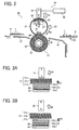
- FIG. 2 is a vertical sectional view of the fixing device 20.
- FIG. 3A is a partially enlarged vertical sectional view of the fixing belt 21 of the fixing device 20 in a state in which the fixing belt 21 is rotated.
- FIG. 3B is a partially enlarged vertical sectional view of the fixing belt 21 in a state in which the fixing belt 21 is not rotated.
- FIGS. 3A and 3B also illustrate multiple layers of the fixing belt 21 and a heat generator 23 of the fixing device 20.
- the fixing device 20 includes the fixing belt 21 formed into a loop; a nip formation pad 22, the heat generator 23, a magnetic member 24, and a tension spring 27, which are disposed inside the loop formed by the fixing belt 21; and a permanent magnet 26, the pressing roller 31, guides 35 and 37, a temperature sensor 40, and a driver 45, which are disposed outside the loop formed by the fixing belt 21.
- the fixing belt 21 is a flexible, thin, endless belt serving as a fixing member or a fixing rotary body that rotates or moves clockwise in FIG. 2 in a rotation direction R1.
- the fixing belt 21 having a thickness not greater than 1 mm and a loop diameter of 40 mm when assuming its operative looped shape, is constructed of a base layer 21a; an elastic layer 21b disposed on the base layer 21a; and a release layer 21c disposed on the elastic layer 21b.
- the base layer 21a constitutes an inner circumferential surface of the fixing belt 21, that is, a contact face sliding over the nip formation pad 22 and the heat generator 23 disposed inside the loop formed by the fixing belt 21.
- the base layer 21a has a thickness of 200 ⁇ m and is made of polyimide (PI).
- the elastic layer 21b made of a rubber material such as silicon rubber, silicon rubber foam, and/or fluorocarbon rubber, has a thickness in a range of from 100 ⁇ m to 300 ⁇ m.
- the elastic layer 21b eliminates or reduces slight surface asperities of the fixing belt 21 at a nip NP formed between the fixing belt 21 and the pressing roller 31. Accordingly, heat is uniformly transmitted from the fixing belt 21 to a toner image T on a recording medium P passing through the nip NP, minimizing formation of a rough image such as an orange peel image.
- silicon rubber with a thickness of 150 ⁇ m is used as the elastic layer 21b.
- the release layer 21c has a thickness in a range of from 10 ⁇ m to 50 ⁇ m, and is made of tetrafluoroethylene-perfluoroalkylvinylether copolymer (PFA), polytetrafluoroethylene (PTFE), polyimide, polyetherimide, and/or polyether sulfide (PES).
- PFA tetrafluoroethylene-perfluoroalkylvinylether copolymer
- PTFE polytetrafluoroethylene
- PES polyether sulfide
- the release layer 21c releases or separates the toner image T from the fixing belt 21.
- the release layer 21c has a thickness of 30 ⁇ m and is made of PFA.
- the nip formation pad 22 Inside the loop formed by the fixing belt 21 are disposed the nip formation pad 22, the heat generator 23, the magnetic member 24, the tension spring 27, and an insulator 29 depicted in FIGS. 2 and 3A .
- the permanent magnet 26 Outside the loop formed by the fixing belt 21 is the permanent magnet 26 disposed opposite the fixing belt 21 with a predetermined gap between the permanent magnet 26 and a part of an outer circumferential surface of the fixing belt 21.
- a lubricant is applied to the inner circumferential surface of the fixing belt 21 to reduce friction between an outer circumferential surface of the nip formation pad 22 and the heat generator 23 and the inner circumferential surface of the fixing belt 21 sliding over the nip formation pad 22 and the heat generator 23.
- the nip formation pad 22 contacting the inner circumferential surface of the fixing belt 21 is a stationary member fixedly disposed inside the loop formed by the fixing belt 21; thus, the rotating fixing belt 21 slides over the stationary, nip formation pad 22. Further, the nip formation pad 22 presses against the pressing roller 31 via the fixing belt 21 to form the nip NP between the fixing belt 21 and the pressing roller 31 through which the recording medium P bearing the toner image T passes. Lateral ends of the nip formation pad 22 in a longitudinal direction thereof parallel to an axial direction of the fixing belt 21 are mounted on and supported by side plates of the fixing device 20, respectively.
- the nip formation pad 22 is made of a rigid material that prevents substantial bending of the nip formation pad 22 by pressure applied from the pressing roller 31.
- the nip formation pad 22 is constituted by an opposed face (e.g., a contact face that contacts the inner circumferential surface of the fixing belt 21 sliding over the nip formation pad 22) facing the pressing roller 31 and having a concave shape corresponding to the curvature of the pressing roller 31.
- the recording medium P moves along the concave opposed face of the nip formation pad 22 in conformity with the curvature of the pressing roller 31 and is discharged from the nip NP in a direction Y11.
- the concave shape of the nip formation pad 22 prevents the recording medium P bearing the fixed toner image T from adhering to the fixing belt 21, thereby facilitating separation of the recording medium P from the fixing belt 21.
- the nip formation pad 22 has a concave shape to form the concave nip NP.
- the nip formation pad 22 may have a flat, planar shape to form a planar nip NP.
- the opposed face of the nip formation pad 22 disposed opposite the pressing roller 31 may have a flat, planar shape. Accordingly, the planar nip NP formed by the planar opposed face of the nip formation pad 22 is substantially parallel to an imaged side of the recording medium P. Consequently, the fixing belt 21 pressed by the planar opposed face of the nip formation pad 22 is precisely adhered to the recording medium P to improve fixing performance. Further, the increased curvature of the fixing belt 21 at an exit of the nip NP facilitates separation of the recording medium P discharged from the nip NP from the fixing belt 21.
- the substantially semi-cylindrical heat generator 23 is disposed opposite the permanent magnet 26 via the fixing belt 21 at a section of the fixing belt 21 other than the nip NP.
- the heat generator 23 and the permanent magnet 26 are disposed directly opposite the nip NP, although their location is not limited thereto.
- the heat generator 23 separably contacts the inner circumferential surface of the fixing belt 21. Shafts protruding from lateral ends of the heat generator 23 in a longitudinal direction thereof parallel to the axial direction of the fixing belt 21, respectively, engage slots provided in the side plates of the fixing device 20 via bearings, respectively, to slidably support the heat generator 23 in a diametrical direction of the fixing belt 21.
- the heat generator 23 is constructed of multiple layers: a base layer 23a constituting an inner circumferential surface disposed opposite the insulator 29; a heat generation layer 23b, including a resistance heat generator, disposed on the base layer 23a; and a protective layer 23c, that is, an insulating layer disposed on the heat generation layer 23b.
- the heat generator 23 has a length of 320 mm in the longitudinal direction thereof and a length, that is, an arcuate length, of 10 mm in a circumferential direction thereof.
- the base layer 23a is made of aluminum oxide (alumina) and/or aluminum nitride.
- the heat generation layer 23b is made of a resistance heat generator, that is, a laminated heat generator made of ceramic. Lateral ends of the heat generation layer 23b in a longitudinal direction thereof parallel to the axial direction of the fixing belt 21 are connected to a power source. When the heat generation layer 23b is supplied with an electric current, it is heated by its electric resistance, thus heating the fixing belt 21 that either contacts or is disposed opposite the heat generator 23. It is to be noted that the heat generation layer 23b may be any device capable of generating heat, such as a metal dispersion resin with an adjusted resistance.
- the protective layer 23c is made of an insulating material, such as glass, that prevents the electric current applied to the heat generator 23 from flowing to the fixing belt 21.
- the base layer 23a of the heat generator 23 is mounted with the magnetic member 24 via the insulator 29.
- the heat generator 23 generates heat by itself, conducting the heat therefrom to the fixing belt 21. Then, the heat is applied from the outer circumferential surface of the heated fixing belt 21 to a toner image T on a recording medium P depicted in FIG. 2 as the recording medium P passes through the nip NP formed between the fixing belt 21 and the pressing roller 31.
- the temperature sensor 40 disposed opposite the outer circumferential surface of the fixing belt 21, serves as a temperature detector that detects a temperature of the outer circumferential surface of the fixing belt 21.
- the temperature sensor 40 may be for example, a thermistor, a thermopile, or the like.
- a controller 6 depicted in FIG. 1 that is, a central processing unit (CPU) provided with a random-access memory (RAM) and a read-only memory (ROM), for example, controls output of the power source that applies the electric current to the heat generator 23, thus adjusting the temperature of the fixing belt 21 to a desired fixing temperature.
- CPU central processing unit
- RAM random-access memory
- ROM read-only memory
- the heat generator 23 has multiple layers including the heat generation layer 23b.
- the heat generator 23 may have a single layer, that is, the heat generation layer 23b only.
- the permanent magnet 26 is disposed opposite the magnetic member 24 via the fixing belt 21 and the heat generator 23.
- the permanent magnet 26 may be a ferromagnetic magnet, for example, a rare-earth magnet or a magnet made of a hard magnetic material such as neodymium-iron-boron alloy.
- the permanent magnet 26 is slidably moved over a frame of the fixing device 20, for example, by the driver 45 bidirectionally as indicated by the double-headed arrow A1 in FIG. 2 to change a distance between the permanent magnet 26 and the magnetic member 24.
- the driver 45 moves the permanent magnet 26 in the diametrical direction of the fixing belt 21, the permanent magnet 26 alternately applies or ceases to apply a magnetic force to the magnetic member 24 or changes a magnitude of the magnetic force exerted on the magnetic member 24, thus moving the heat generator 23 together with the magnetic member 24 in the diametrical direction of the fixing belt 21, a detailed description of which is deferred.
- the driver 45 that moves the permanent magnet 26 may be a mechanism that includes a cam contacting the permanent magnet 26 biased upward in FIG. 2 by a spring.
- a fan that cools the permanent magnet 26 may be added to minimize the decrease in magnetic permeability due to the heated permanent magnet 26.
- the substantially semi-cylindrical magnetic member 24 is attached to the heat generator 23 and is disposed opposite the fixing belt 21 via the heat generator 23.
- the magnetic member 24 may be made of soft ferrite, but preferably is made of hard ferrite.
- the magnetic member 24 made of hard ferrite need to be disposed with respect to the permanent magnet 26 in such a manner that an attractive force is generated between the magnetic member 24 and the permanent magnet 26.
- the south pole of the magnetic member 24 is disposed opposite the north pole of the permanent magnet 26, thus moving the heat generator 23 attached to the magnetic member 24 bidirectionally in the diametrical direction of the fixing belt 21 precisely by slidable movement of the permanent magnet 26, a detailed description of which is deferred.
- the insulator 29 is provided between the heat generator 23 and the magnetic member 24.
- the insulator 29 With the above-described configuration of the insulator 29 combined with the heat generator 23 and the magnetic member 24, in accordance with the bidirectional movement of the permanent magnet 26 as indicated by the double-headed arrow A1 in FIG. 2 , the insulator 29 also moves bidirectionally in the diametrical direction of the fixing belt 21 as indicated by the double-headed arrow A1 together with the heat generator 23 and the magnetic member 24.
- the tension spring 27 has one end in a longitudinal direction thereof which is attached to the heat generator 23, the magnetic member 24, and the insulator 29 and another end in the longitudinal direction thereof which is attached to a frame of the fixing device 20.
- the tension spring 27 serves as a biasing member that biases the magnetic member 24, the insulator 29, and the heat generator 23, against a magnetic force of the permanent magnet 26 to separate the heat generator 23 combined with the magnetic member 24 and the insulator 29 from the fixing belt 21 downward in FIG. 2 in a direction D2.
- the pressing roller 31 serves as a pressing rotary body that presses against the nip formation pad 22 via the fixing belt 21 by contacting the outer circumferential surface of the fixing belt 21 at the nip NP.
- the pressing roller 31 is constructed of a hollow metal core 32 and an elastic layer 33 disposed on the metal core 32.
- the elastic layer 33 having a thickness of 3 mm, is made of silicon rubber foam, silicon rubber, and/or fluorocarbon rubber.
- a thin surface release layer made of PFA and/or PTFE may be disposed on the elastic layer 33.
- a gear engaging a driving gear of a driving mechanism that drives and rotates the pressing roller 31 counterclockwise in FIG. 2 in a rotation direction R2 counter to the rotation direction R1 of the fixing belt 21.
- Lateral ends of the pressing roller 31 in a longitudinal direction, that is, an axial direction thereof, are rotatably supported by the side plates of the fixing device 20 via bearings, respectively.
- a heat source such as a halogen heater, may be disposed inside the pressing roller 31.
- the pressing roller 31 applies decreased pressure to the nip formation pad 22 via the fixing belt 21 at the nip NP to decrease bending of the nip formation pad 22. Further, the pressing roller 31 provides increased heat insulation that minimizes heat conduction thereto from the fixing belt 21, improving heating efficiency of the fixing belt 21.
- the fixing device 20 includes two guide plates, the guide 35, that is, an entry guide plate, disposed at an entry to the nip NP and the guide 37, that is, an exit guide plate, disposed at an exit of the nip NP.
- the guide 35 is directed to the entry to the nip NP to guide the recording medium P conveyed in a direction Y10 from the transfer device 7 depicted in FIG. 1 to the nip NP.
- the guide 37 is directed to a conveyance path downstream from the fixing device 20 in the recording medium conveyance direction to guide the recording medium P discharged from the nip NP in the direction Y11 to the conveyance path. Both the guides 35 and 37 are mounted on the frame (e.g., a body) of the fixing device 20.
- the power source supplies an electric current to the heat generator 23; at the same time, the pressing roller 31 starts rotating in the rotation direction R2. Accordingly, the fixing belt 21 rotates in accordance with rotation of the pressing roller 31 in the rotation direction R1 counter to the rotation direction R2 of the pressing roller 31 due to friction therebetween at the nip NP.
- the toner image T formed on the photoconductive drum 5 as described above is transferred onto a recording medium P sent from one of the paper trays 12, 13, and 14. Being guided by the guide 35, the recording medium P bearing the toner image T is conveyed from the transfer nip in the direction Y10 toward the nip NP, entering the nip NP formed between the fixing belt 21 and the pressing roller 31 pressed against each other.
- the recording medium P bearing the toner image T passes through the nip NP, it receives heat from the heated fixing belt 21 and pressure from the fixing belt 21, the nip formation pad 22, and the pressing roller 31 that form the nip NP.
- the toner image T is fixed on the recording medium P by the heat and the pressure applied at the nip NP.
- the recording medium P bearing the fixed toner image T is discharged from the nip NP and conveyed in the direction Y11 as guided by the guide 37.
- the following describes the configuration of the fixing device 20 according to a first illustrative embodiment of the present invention.
- the fixing device 20 includes a moving assembly 60, constructed of the magnetic member 24, the permanent magnet 26, the tension spring 27, and the driver 45, which moves the heat generator 23 combined with the magnetic member 24 and the insulator 29 to change the pressure with which the heat generator 23 presses against the fixing belt 21 or, if separated from the fixing belt 21, a distance between the heat generator 23 and the fixing belt 21 disposed opposite the heat generator 23.
- the moving assembly 60 moves the heat generator 23 bidirectionally in a direction D3 shown in FIG. 3A and a direction D5 shown in FIG. 3B .
- the permanent magnet 26 is disposed opposite the magnetic member 24 via the fixing belt 21, the heat generator 23, and the insulator 29, and is slidably moved by the driver 45 depicted in FIG. 2 bidirectionally toward and away from the fixing belt 21, changing a distance between the permanent magnet 26 and the magnetic member 24.
- the magnetic member 24, together with the insulator 29, is attached to the heat generator 23 in such a manner that it is disposed opposite the fixing belt 21 via the insulator 29 and the heat generator 23.
- the magnetic member 24 and the heat generator 23 are biased by the tension spring 27 in the direction D2 away from the fixing belt 21.
- the permanent magnet 26 exerts an increased magnetic attractive force on the magnetic member 24 against a biasing force of the tension spring 27 depicted in FIG. 2 , thus moving the heat generator 23 together with the magnetic member 24 upward in the direction D3.
- the heat generator 23 presses against the fixing belt 21 with an increased pressure or, if separated from the fixing belt 21, is disposed opposite the fixing belt 21 with a decreased distance between the heat generator 23 and the fixing belt 21, thus improving heat conductivity from the heat generator 23 to the fixing belt 21, that is, activating heat conduction from the heat generator 23 to the fixing belt 21.
- the permanent magnet 26 exerts a decreased magnetic attractive force on the magnetic member 24 against a biasing force of the tension spring 27, thus moving the heat generator 23 together with the magnetic member 24 downward in the direction D5.
- the heat generator 23 presses against the fixing belt 21 with a decreased pressure or is disposed opposite the fixing belt 21 with an increased distance between the heat generator 23 and the fixing belt 21. That is, the heat generator 23 is isolated from the fixing belt 21 with no pressure therebetween, thus degrading heat conductivity from the heat generator 23 to the fixing belt 21, that is, deactivating heat conduction from the heat generator 23 to the fixing belt 21.
- the fixing device 20 employs the permanent magnet 26 that moves the heat generator 23 by magnetic force without contacting the heat generator 23, preventing elements of the fixing device 20 other than the fixing belt 21 from drawing heat generated by the heat generator 23 and thereby maintaining heating efficiency of the fixing belt 21.
- the driver 45 moves the permanent magnet 26 in such a manner that the position of the permanent magnet 26 is switchable between the two positions: a first position shown in FIG. 3A , where the permanent magnet 26 is disposed closer to the fixing belt 21 and the magnetic member 24 with a gap of 0.2 mm or smaller, preferably 0.1 mm or smaller, between the fixing belt 21 and the heat generator 23; and a second position shown in FIG. 3B , where the permanent magnet 26 is disposed away from the fixing belt 21 and the magnetic member 24 with a greater gap of at least 0.2 mm between the fixing belt 21 and the heat generator 23.
- the fixing device 20 may further include a stopper that restricts an amount of movement of the heat generator 23 moving upward in the direction D3 and downward in the direction D5 in accordance with movement of the permanent magnet 26 as described above, thus facilitating adjustment of the pressure with which the heat generator 23 presses against the fixing belt 21 or the distance between the heat generator 23 and the fixing belt 21 within a target range.
- a stopper that restricts an amount of movement of the heat generator 23 moving upward in the direction D3 and downward in the direction D5 in accordance with movement of the permanent magnet 26 as described above, thus facilitating adjustment of the pressure with which the heat generator 23 presses against the fixing belt 21 or the distance between the heat generator 23 and the fixing belt 21 within a target range.
- the moving assembly 60 that moves the heat generator 23 is controlled by the controller 6 depicted in FIG. 1 according to rotation of the fixing belt 21. For example, when the fixing belt 21 does not rotate, the moving assembly 60 moves the heat generator 23 to a position where the heat generator 23 presses against the fixing belt 21 with a pressure smaller than that when the fixing belt 21 rotates or to a position where the heat generator 23 is disposed opposite the fixing belt 21 with a distance greater than that when the fixing belt 21 rotates.
- the driver 45 moves the permanent magnet 26 to the first position shown in FIG. 3A where the permanent magnet 26 is disposed closer to the fixing belt 21, causing the heat generator 23 to contact the fixing belt 21 or causing the heat generator 23 to be disposed opposite the fixing belt 21 with a slight gap therebetween allowing heat conduction from the heat generator 23 to the fixing belt 21.
- the fixing belt 21 rotates clockwise in FIG.
- a contact section on the inner circumferential surface of the fixing belt 21 where the fixing belt 21 contacts the heat generator 23 and is heated by the heat generator 23 moves in the circumferential direction of the fixing belt 21, resulting in efficient and uniform heating of the fixing belt 21 over the circumferential direction thereof.
- the driver 45 moves the permanent magnet 26 to the second position shown in FIG. 3B where the permanent magnet 26 is disposed away from the fixing belt 21, thus isolating the heat generator 23 from the fixing belt 21 or separating the heat generator 23 from the fixing belt 21 with a substantial gap therebetween that prohibits heat conduction from the heat generator 23 to the fixing belt 21.
- the fixing belt 21, although it does not rotate is not heated by the heat generator 23 locally, preventing temperature variation of the fixing belt 21 in the circumferential direction thereof, that is, the rotation direction R1.
- heat radiated from the heat generator 23 isolated from the fixing belt 21 sufficiently reaches the fixing belt 21 substantially uniformly over the circumferential direction of the fixing belt 21, thus heating the fixing belt 21 uniformly over the circumferential direction thereof although heating efficiency is degraded compared to when the heat generator 23 contacting the fixing belt 21 conducts heat to the fixing belt 21. Accordingly, even when a recording medium P is conveyed to the nip NP for the fixing process immediately after the standby mode is finished, faulty fixing does not occur due to variation in the temperature of the fixing belt 21 in the circumferential direction thereof.
- the controller 6 controls the moving assembly 60 to move the heat generator 23 to the position where the heat generator 23 presses against the fixing belt 21 with a decreased pressure or is disposed opposite the fixing belt 21 with a greater distance therebetween compared to when conveyance of the recording medium P through the nip NP is ongoing.
- the driver 45 moves the permanent magnet 26 to the first position shown in FIG. 3A where the permanent magnet 26 is disposed closer to the fixing belt 21, causing the heat generator 23 to contact the fixing belt 21 or causing the heat generator 23 to be disposed opposite the fixing belt 21 with a slight gap therebetween allowing heat conduction from the heat generator 23 to the fixing belt 21. Simultaneously, as the fixing belt 21 rotates clockwise in FIG.
- the contact section on the inner circumferential surface of the fixing belt 21 where the fixing belt 21 contacts the heat generator 23 and is heated by the heat generator 23 moves in the circumferential direction of the fixing belt 21, resulting in efficient and uniform heating of the fixing belt 21 over the circumferential direction thereof.
- the driver 45 moves the permanent magnet 26 to the second position shown in FIG. 3B where the permanent magnet 26 is disposed away from the fixing belt 21, thus isolating the heat generator 23 from the fixing belt 21 or moving the heat generator 23 downward in the direction D5 to the position where the heat generator 23 presses against the fixing belt 21 with a slight pressure of 0.1 kgf/cm 2 or smaller.
- the configuration according to the first illustrative embodiment changes the pressure with which the heat generator 23 presses against the fixing belt 21 or the distance between the heat generator 23 and the fixing belt 21 disposed opposite the heat generator 23.
- the heat generator 23 can heat the fixing belt 21 efficiently.
- temperature variation of the fixing belt 21 does not arise in the rotation direction R1 thereof.
- the permanent magnet 26 generates an attractive force between the permanent magnet 26 and the magnetic member 24 and at the same time the tension spring 27 exerts a biasing force on the magnetic member 24 and the heat generator 23 downward in FIG. 2 in the direction D2 to separate the heat generator 23 from the fixing belt 21.
- the permanent magnet 26 may generate a repulsive force between the permanent magnet 26 and the magnetic member 24 and at the same time a biasing member (e.g., a compression spring) may exert a biasing force (e.g., a compressive force) on the magnetic member 24 and the heat generator 23 upward in FIG. 2 in a direction opposite the direction D2 to move the heat generator 23 closer to the fixing belt 21, thus attaining effects equivalent to the effects of the first illustrative embodiment.
- a biasing member e.g., a compression spring
- the configuration according to the first illustrative embodiment uses the permanent magnet 26 as a magnet that slidably moves over the frame of the fixing device 20 in the diametrical direction of the fixing belt 21 and exerts a magnetic force on the magnetic member 24 to cause the heat generator 23 to contact and separate from the fixing belt 21 or change pressure with which the heat generator 23 presses against the fixing belt 21.
- an electromagnet or a superconducting magnet may be used as a magnet that exerts a magnetic force on the magnetic member 24.
- Such magnets can also slidably move to cause the heat generator 23 to contact and separate from the fixing belt 21 or change pressure with which the heat generator 23 presses against the fixing belt 21, thus attaining effects equivalent to the effects of the first illustrative embodiment.
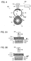
- FIGS. 4, 5A, and 5B the following describes a fixing device 20S according to a second illustrative embodiment.
- FIG. 4 is a vertical sectional view of the fixing device 20S.
- FIG. 5A is a partially enlarged vertical sectional view of the fixing belt 21 of the fixing device 20 in a state in which the fixing belt 21 is rotated.
- FIG. 5B is a partially enlarged vertical sectional view of the fixing belt 21 in a state in which the fixing belt 21 is not rotated.
- the fixing device 20S according to the second illustrative embodiment includes a permanent magnet 26S that is rotatably movable.
- the fixing device 20S according to the second illustrative embodiment includes the fixing belt 21 formed into a loop; the nip formation pad 22, the heat generator 23, and the magnetic member 24, which are disposed inside the loop formed by the fixing belt 21; and the permanent magnet 26S, the pressing roller 31, the temperature sensor 40, and a driver 46, which are disposed outside the loop formed by the fixing belt 21.
- the fixing device 20S further includes a moving assembly 60S that moves the heat generator 23 combined with the magnetic member 24 and the insulator 29 to change pressure with which the heat generator 23 presses against the fixing belt 21 or a distance between the heat generator 23 and the fixing belt 21 disposed opposite the heat generator 23.
- the moving assembly 60S includes the permanent magnet 26S, the magnetic member 24, and the driver 46 that drives and rotates the permanent magnet 26S.
- the permanent magnet 26S disposed opposite the magnetic member 24 via the fixing belt 21 and the heat generator 23, is rotated about a rotary shaft 26a by the driver 46 to change the magnetic pole, that is, the north pole or the south pole, of the permanent magnet 26S disposed opposite the magnetic member 24.
- the magnetic member 24, together with the insulator 29 depicted in FIG. 5A is adhered to the heat generator 23 in such a manner that the magnetic member 24 is disposed opposite the fixing belt 21 via the insulator 29 and the heat generator 23.
- the driver 46 depicted in FIG. 4 rotates the permanent magnet 26S to a first position shown in FIG. 5A where the north pole of the permanent magnet 26S is disposed opposite the fixing belt 21 and the magnetic member 24; thus, the permanent magnet 26S exerts a magnetic attractive force on the magnetic member 24, which moves the heat generator 23, together with the magnetic member 24, upward in a direction D7 as shown in FIG. 5A .
- the heat generator 23 presses against the fixing belt 21 with an increased pressure or is disposed opposite the fixing belt 21 with a decreased distance therebetween, improving heat conducting efficiency from the heat generator 23 to the fixing belt 21.
- the driver 46 rotates the permanent magnet 26S to a second position shown in FIG. 5B where the south pole of the permanent magnet 26S is disposed opposite the fixing belt 21 and the magnetic member 24; thus, the permanent magnet 26S exerts a magnetic repulsive force on the magnetic member 24, which moves the heat generator 23, together with the magnetic member 24, downward in a direction D8 as shown in FIG. 5B .
- the heat generator 23 presses against the fixing belt 21 with a decreased pressure or is disposed opposite the fixing belt 21 with an increased distance therebetween, that is, the heat generator 23 separates from the fixing belt 21, rendering pressure between the heat generator 23 and the fixing belt 21 to zero. Accordingly, the fixing belt 21, which is heated by heat conduction from the heat generator 23, is now heated by heat radiation from the heat generator 23, thus minimizing localized overheating of the fixing belt 21 while the fixing belt 21 does not rotate.
- the south pole of the magnetic member 24 is disposed opposite the permanent magnet 26S.
- the tension spring 27 of the fixing device 20 since the permanent magnet 26S biases the magnetic member 24 and the heat generator 23 attached to the magnetic member 24 by its magnetic repulsive force to separate the heat generator 23 from the fixing belt 21, the tension spring 27 of the fixing device 20 according to the first illustrative embodiment shown in FIG. 2 is not attached to the magnetic member 24.
- the tension spring 27 may be attached to the magnetic member 24 to add a supplementary biasing force that separates the heat generator 23 and the magnetic member 24 from the fixing belt 21.
- the configuration according to the second illustrative embodiment changes the pressure with which the heat generator 23 presses against the fixing belt 21 or the distance between the heat generator 23 and the fixing belt 21 disposed opposite the heat generator 23.
- the heat generator 23 can heat the fixing belt 21 efficiently.
- temperature variation of the fixing belt 21 does not arise in the rotation direction R1 thereof.
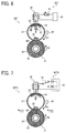
- a fixing device 20T according to a third illustrative embodiment and a fixing device 20TV as a variation of the fixing device 20T.
- FIG. 6 is a vertical sectional view of the fixing device 20T.
- FIG. 7 is a vertical sectional view of the fixing device 20TV as a variation of the fixing device 20T shown in FIG. 6 .
- the fixing devices 20T and 20TV according to the third illustrative embodiment include an electromagnet 28.
- the fixing device 20T includes the fixing belt 21 formed into a loop; the nip formation pad 22, the heat generator 23, the magnetic member 24, and the tension spring 27, which are disposed inside the loop formed by the fixing belt 21; and the electromagnet 28, the pressing roller 31, the temperature sensor 40, a power source 50, and a variable resistor 51, which are disposed outside the loop formed by the fixing belt 21.
- the fixing device 20T further includes a moving assembly 60T that moves the heat generator 23 combined with the magnetic member 24 and the insulator 29 depicted in FIG. 3A to change pressure with which the heat generator 23 presses against the fixing belt 21 or a distance between the heat generator 23 and the fixing belt 21 disposed opposite the heat generator 23.
- the moving assembly 60T includes the electromagnet 28, the magnetic member 24, the tension spring 27, the power source 50, and the variable resistor 51.
- the electromagnet 28 is disposed opposite the magnetic member 24 via the fixing belt 21 and the heat generator 23.
- the variable resistor 51 changes an amount of electric current applied to the electromagnet 28 (e.g., an electromagnetic coil) from the power source 50 to change a magnetic force exerted on the magnetic member 24.
- the magnetic member 24, together with the insulator 29 depicted in FIG. 3A is adhered to the heat generator 23 in such a manner that the magnetic member 24 is disposed opposite the fixing belt 21 via the insulator 29 and the heat generator 23.
- the controller 6 depicted in FIG. 1 controls the variable resistor 51 to supply an increased amount of electric current from the power source 50 to the electromagnet 28; thus, the electromagnet 28 exerts an increased magnetic attractive force on the magnetic member 24 against a biasing force of the tension spring 27, moving the heat generator 23, together with the magnetic member 24, upward in FIG. 6 .
- the heat generator 23 presses against the fixing belt 21 with an increased pressure or is disposed opposite the fixing belt 21 with a decreased distance therebetween, improving heat conducting efficiency from the heat generator 23 to the fixing belt 21.
- the controller 6 controls the variable resistor 51 to supply a decreased amount of electric current from the power source 50 to the electromagnet 28; thus, the electromagnet 28 exerts a decreased magnetic attractive force on the magnetic member 24, moving the heat generator 23, together with the magnetic member 24, downward in FIG. 6 with a biasing force of the tension spring 27.
- the heat generator 23 presses against the fixing belt 21 with a decreased pressure or is disposed opposite the fixing belt 21 with an increased distance therebetween, that is, the heat generator 23 separates from the fixing belt 21, rendering pressure between the heat generator 23 and the fixing belt 21 to zero. Accordingly, the fixing belt 21, which is heated by heat conduction from the heat generator 23, is now heated by heat radiation from the heat generator 23, thus minimizing localized overheating of the fixing belt 21 while the fixing belt 21 does not rotate.
- the controller 6 controls the variable resistor 51 to change the amount of electric current supplied from the power source 50 to the electromagnet 28, thus causing the heat generator 23 to contact and separate from the fixing belt 21.
- the controller 6 may change a direction in which the electric current is applied to the electromagnet 28 to change the magnetic pole thereof, that is, the north pole or the south pole, which exerts a magnetic force on the magnetic member 24, thus causing the heat generator 23 to contact and separate from the fixing belt 21.
- the electromagnet 28 is disposed opposite the magnetic member 24 via the fixing belt 21 and the heat generator 23.
- the fixing device 20TV includes a switching circuit 52 that changes the direction in which the power source 50 applies the electric current to the electromagnet 28, thus changing the magnetic polarity of the electromagnet 28 that exerts a magnetic force on the magnetic member 24.
- the fixing device 20TV as a variation of the fixing device 20T according to the third illustrative embodiment includes the fixing belt 21 formed into a loop; the nip formation pad 22, the heat generator 23, and the magnetic member 24, which are disposed inside the loop formed by the fixing belt 21; and the electromagnet 28, the pressing roller 31, the temperature sensor 40, the power source 50, and the switching circuit 52, which are disposed outside the loop formed by the fixing belt 21.
- the fixing device 20TV further includes a moving assembly 60TV that moves the heat generator 23 combined with the magnetic member 24 and the insulator 29 depicted in FIG. 3A to change pressure with which the heat generator 23 presses against the fixing belt 21 or a distance between the heat generator 23 and the fixing belt 21 disposed opposite the heat generator 23.
- the moving assembly 60TV includes the electromagnet 28, the magnetic member 24, the power source 50, and the switching circuit 52.
- the controller 6 depicted in FIG. 1 controls the switching circuit 52 to change the direction in which the power source 50 applies the electric current to the electromagnet 28, causing the north pole of the electromagnet 28 to be disposed opposite the fixing belt 21 and the magnetic member 24; thus, the electromagnet 28 exerts a magnetic attractive force on the magnetic member 24, moving the heat generator 23, together with the magnetic member 24, upward in FIG. 7 .
- the heat generator 23 presses against the fixing belt 21 with an increased pressure or is disposed opposite the fixing belt 21 with a decreased distance therebetween, improving heat conducting efficiency from the heat generator 23 to the fixing belt 21.
- the controller 6 controls the switching circuit 52 to change the direction in which the power source 50 applies the electric current to the electromagnet 28, causing the south pole of the electromagnet 28 to be disposed opposite the fixing belt 21 and the magnetic member 24; thus, the electromagnet 28 exerts a magnetic repulsive force on the magnetic member 24, moving the heat generator 23, together with the magnetic member 24, downward in FIG. 7 .
- the heat generator 23 presses against the fixing belt 21 with a decreased pressure or is disposed opposite the fixing belt 21 with an increased distance therebetween, that is, the heat generator 23 separates from the fixing belt 21, rendering pressure between the heat generator 23 and the fixing belt 21 to zero. Accordingly, the fixing belt 21, which is heated by heat conduction from the heat generator 23, is now heated by heat radiation from the heat generator 23, thus minimizing localized overheating of the fixing belt 21 while the fixing belt 21 does not rotate.
- the south pole of the magnetic member 24 is disposed opposite the electromagnet 28.
- the configurations according to the third illustrative embodiment and the variation thereof change the pressure with which the heat generator 23 presses against the fixing belt 21 or the distance between the heat generator 23 and the fixing belt 21 disposed opposite the heat generator 23.
- the heat generator 23 can heat the fixing belt 21 efficiently.
- temperature variation of the fixing belt 21 does not arise in the rotation direction R1 thereof.
- FIGS. 8, 9A, and 9B the following describes a fixing device 20U according to a fourth illustrative embodiment.
- FIG. 8 is a vertical sectional view of the fixing device 20U.
- FIG. 9A is a partially enlarged vertical sectional view of a fixing belt 21U installed in the fixing device 20U in a state in which it is rotated.
- FIG. 9B is a partially enlarged vertical sectional view of the fixing belt 21U in a state in which it is not rotated.
- the fixing device 20U according to the fourth illustrative embodiment has the configuration in which a heat generator 23U is heated by an exciting coil unit 25 by electromagnetic induction.
- the fixing device 20U includes the fixing belt 21U formed into a loop; the nip formation pad 22, the heat generator 23U, the magnetic member 24, and the tension spring 27, which are disposed inside the loop formed by the fixing belt 21U; and the permanent magnet 26, the driver 45, the pressing roller 31, the temperature sensor 40, and the exciting coil unit 25, which are disposed outside the loop formed by the fixing belt 21U.
- the fixing device 20U further includes the moving assembly 60 that moves the heat generator 23U combined with the magnetic member 24 and the insulator 29 depicted in FIG. 3A to change pressure with which the heat generator 23U presses against the fixing belt 21U or a distance between the heat generator 23U and the fixing belt 21U disposed opposite the heat generator 23U.
- the moving assembly 60 includes the permanent magnet 26, the magnetic member 24, the tension spring 27, and the driver 45.
- the exciting coil 25a extending in a longitudinal direction of the exciting coil unit 25 parallel to the axial direction of the fixing belt 21U, is constructed of litz wire formed by bundling thin wire and wound around the exciting coil core 25b that covers a part of an outer circumferential surface of the fixing belt 21U.
- the exciting coil core 25b made of ferromagnet (e.g., ferrite) having a relative permeability of 2,500, generates a magnetic flux toward a heat generation layer of the fixing belt 21U and a heat generation layer of the heat generator 23U efficiently.
- the fixing belt 21U is constructed of three layers: a base layer 21d constituting an inner circumferential surface of the fixing belt 21U, that is, a contact face that slides over the nip formation pad 22 and the heat generator 23U; the elastic layer 21b disposed on the base layer 21d; and the release layer 21c disposed on the elastic layer 21b.
- the base layer 21d having a thickness of from several microns to several hundred microns, is made of a magnetic material, such as SUS420 stainless steel or Fe-Ni alloy, thus serving as a heat generation layer heated by the exciting coil unit 25 by electromagnetic induction.
- the configuration of the elastic layer 21b and the release layer 21c of the fixing belt 21U is identical to that of the fixing belt 21 depicted in FIG. 2 installed in the fixing device 20 according to the first illustrative embodiment.
- the heat generator 23U is constructed of three layers like the heat generator 23 of the fixing device 20 shown in FIG. 3A , however, the configuration of the three layers is different from that of the heat generator 23.
- the heat generator 23U includes an antioxidant layer 23e constituting an inner circumferential surface of the heat generator 23U, that is, an opposed face disposed opposite the magnetic member 24; a heat generation layer 23f disposed on the antioxidant layer 23e; and an antioxidant layer 23g disposed on the heat generation layer 23f.
- the heat generation layer 23f having a thickness of 10 ⁇ m, is made of copper. As an exciting magnetic flux generated by the exciting coil unit 25 passes through the heat generation layer 23f, it induces an eddy current that heats the heat generation layer 23f by electromagnetic induction.
- Each of the antioxidant layers 23e and 23g having a thickness of 30 ⁇ m, is made of nickel plate; the antioxidant layers 23e and 23g sandwich the heat generation layer 23f, inhibiting oxidation of the heat generation layer 23f.
- the heat generator 23U is heated by electromagnetic induction by an alternating magnetic field generated by the exciting coil unit 25, thus heating the fixing belt 21U contacting the heat generator 23U. That is, the exciting coil unit 25 heats the heat generator 23U directly by electromagnetic induction and heats the fixing belt 21U indirectly via the heat generator 23U by heat conduction from the heat generator 23U to the fixing belt 21U.
- the fixing belt 21U has the base layer 21d that functions as a heat generation layer
- the fixing belt 21U itself that is, the base layer 21d
- the fixing belt 21U is also heated directly by electromagnetic induction by the alternating magnetic field generated by the exciting coil unit 25. That is, the fixing belt 21U is heated directly by electromagnetic induction by the exciting coil unit 25 and at the same time is heated indirectly by the exciting coil unit 25 by heat conduction from the heat generator 23U heated by electromagnetic induction by the exciting coil unit 25, improving heating efficiency of the fixing belt 21U.
- the heated fixing belt 21U heats a recording medium P bearing a toner image T.
- the controller 6 depicted in FIG. 1 controls output of the exciting coil unit 25 based on a detection result provided from the temperature sensor 40 disposed opposite the outer circumferential surface of the fixing belt 21U to detect a temperature thereof, thus adjusting the temperature of the fixing belt 21U to a desired fixing temperature.
- a highfrequency power source supplies an alternating electric current to the exciting coil 25a of the exciting coil unit 25, and at the same time the pressing roller 31 starts rotating in the rotation direction R2. Accordingly, the fixing belt 21U rotates in accordance with rotation of the pressing roller 31 in the rotation direction R1 counter to the rotation direction R2 of the pressing roller 31 due to friction therebetween at the nip NP.
- the toner image T formed on the photoconductive drum 5 as described above is transferred onto a recording medium P sent from one of the paper trays 12, 13, and 14.
- the recording medium P bearing the toner image T is conveyed from the transfer nip in the direction Y10 toward the nip NP, entering the nip NP formed between the fixing belt 21U and the pressing roller 31 pressed against each other.
- the recording medium P bearing the toner image T passes through the nip NP, it receives heat from the heated fixing belt 21U and pressure from the fixing belt 21U, the nip formation pad 22, and the pressing roller 31 that form the nip NP.
- the toner image T is fixed on the recording medium P by the heat and the pressure applied at the nip NP.
- the recording medium P bearing the fixed toner image T is discharged from the nip NP and conveyed in the direction Y11.
- the driver 45 moves the permanent magnet 26 to a first position shown in FIG. 9A where the permanent magnet 26 is disposed closer to the fixing belt 21U, thus increasing a magnetic attractive force of the permanent magnet 26 exerted on the magnetic member 24 against a biasing force of the tension spring 27, which moves the heat generator 23U, together with the magnetic member 24, upward in a direction D9.
- the heat generator 23U presses against the fixing belt 21U with an increased pressure or is disposed opposite the fixing belt 21U with a decreased distance therebetween, thus improving heat conductivity from the heat generator 23U to the fixing belt 21U.
- the driver 45 moves the permanent magnet 26 to a second position shown in FIG. 9B where the permanent magnet 26 is disposed away from the fixing belt 21U, thus decreasing a magnetic attractive force of the permanent magnet 26 exerted on the magnetic member 24 and moving the heat generator 23U, together with the magnetic member 24, downward in a direction D10 with a biasing force of the tension spring 27.
- the heat generator 23U presses against the fixing belt 21U with a decreased pressure or is disposed opposite the fixing belt 21U with an increased distance therebetween, that is, the heat generator 23U separates from the fixing belt 21U, rendering pressure between the heat generator 23U and the fixing belt 21U to zero. Accordingly, the fixing belt 21U, which is heated by heat conduction from the heat generator 23U, is now heated by heat radiation from the heat generator 23U, thus minimizing localized overheating of the fixing belt 21U while the fixing belt 21U does not rotate.
- the fixing belt 21U is heated precisely both during rotation and non-rotation. For example, while the fixing belt 21U rotates, it is heated by heat conduction from the heat generator 23U; while the fixing belt 21U does not rotate, it is heated by heat radiation from the heat generator 23U.
- the heat generation layer 23f of the heat generator 23U may be made of a magnetic shunt alloy.
- the base layer 21d that is, the heat generation layer, of the fixing belt 21U is made of a ferromagnetic, magnetic shunt alloy such as iron, nickel, cobalt, or an alloy of these.
- the base layer 21d of the fixing belt 21U has a Curie temperature near an upper temperature limit of the fixing temperature with which the toner image T is fixed on the recording medium P, preventing overheating of the fixing belt 21U with self temperature control of the magnetic shunt alloy and thereby minimizing thermal degradation of the fixing belt 21U.
- the base layer 21d of the fixing belt 21U has a Curie temperature equivalent to a temperature that maintains magnetic permeability against the heated magnetic member 24, rendering the insulator 29 disposed between the heat generator 23U and the magnetic member 24 unnecessary.
- the fixing belt 21U includes the heat generation layer, that is, the base layer 21d, heated by the exciting coil unit 25 by electromagnetic induction.
- the fixing belt 21U may not include the heat generation layer.
- the fixing belt 21U is heated solely by the heat generator 23U by heat conduction or heat radiation, which is heated by the exciting coil unit 25 by electromagnetic induction, thus further enhancing prevention of localized overheating of the fixing belt 21U when the fixing belt 21U does not rotate.
- the configuration according to the fourth illustrative embodiment changes the pressure with which the heat generator 23U presses against the fixing belt 21U or the distance between the heat generator 23U and the fixing belt 21U disposed opposite the heat generator 23U.
- the heat generator 23U can heat the fixing belt 21U efficiently.
- temperature variation of the fixing belt 21U does not arise in the rotation direction R1 thereof.
- the fixing belts 21 and 21U are used as a fixing rotary body that rotates in the predetermined direction of rotation; the pressing roller 31 is used as a pressing rotary body disposed opposite the fixing rotary body to form the nip NP therebetween and rotating in the direction counter to the direction of rotation of the fixing rotary body.
- a fixing film, a fixing roller, or the like may be used as a fixing rotary body; a pressing belt or the like may be used as a pressing rotary body, attaining effects equivalent to the effects of the fixing devices 20, 20S, 20T, 20TV, and 20U according to the above-described exemplary embodiments.
- the fixing devices 20, 20S, 20T, 20TV, and 20U are installed in the image forming apparatus 1 serving as a monochrome copier.
- they may be installed in color image forming apparatuses such as copiers, printers, facsimile machines, and multifunction printers having at least one of copying, printing, scanning, plotter, and facsimile functions, or the like.
- the fixing devices 20, 20S, 20T, and 20TV include the heat generator 23 that generates heat; the fixing device 20U includes the heat generator 23U heated by the exciting coil unit 25 by electromagnetic induction.
- the fixing devices 20, 20S, 20T, 20TV, and 20U may include a heat generator heated by a heater (e.g., a halogen heater) by radiant heat, attaining effects equivalent to the effects of the fixing devices 20, 20S, 20T, 20TV, and 20U according to the above-described exemplary embodiments.
- a heater e.g., a halogen heater
Landscapes
- Physics & Mathematics (AREA)
- General Physics & Mathematics (AREA)
- Fixing For Electrophotography (AREA)
- General Induction Heating (AREA)
Claims (15)
- Fixiervorrichtung (20; 20S; 20T; 20TV; 20U), aufweisend:einen drehbaren Fixierkörper (21; 21U), um sich in einer vorherbestimmten Drehrichtung bzw. Rotationsrichtung zu drehen;einen drehbaren Drück- bzw. Presskörper (31), der gegen den drehbaren Fixierkörper (21; 21U) gedrückt bzw. gepresst wird, um sich in einer Richtung entgegengesetzt zu der Drehrichtung bzw. Rotationsrichtung von dem drehbaren Fixierkörper (21; 21U) zu drehen und um eine Klemmstelle bzw. einen Walzenspalt (NP) dazwischen zu bilden, durch welche bzw. durch welchen ein Aufzeichnungsmedium, das ein Tonerbild trägt, hindurchgeht bzw. befördert wird;eine Wärmeerzeugungseinrichtung (23; 23U); undeine Bewegungsbaugruppe (60; 60S; 60T; 60TV), dadurch gekennzeichnet, dass die Wärmeerzeugungseinrichtung (23; 23U) innerhalb eines Loops bzw. einer Schlinge, der bzw. die durch den drehbaren Fixierkörper (21; 21U) gebildet wird und gegenüber dem drehbaren Fixierkörper (21; 21U) angeordnet ist, und zwar an einem Abschnitt anders als die Klemmstelle bzw. der Walzenspalt (NP), um den drehbaren Fixierkörper (21; 21U) zu beheizen bzw. zu erwärmen,wobei die Bewegungsbaugruppe (60) aufweist:ein magnetisches Glied (24), das an der Wärmeerzeugungseinrichtung (23; 23U) angebracht ist und gegenüber dem drehbaren Fixierkörper (21; 21U) über die Wärmeerzeugungseinrichtung (23; 23U) angeordnet ist; undeinen Permanentmagneten (26), der außerhalb des Loops bzw. der Schlinge, der bzw. die durch den drehbaren Fixierkörper (21; 21U) gebildet wird und gegenüber dem magnetischen Glied (24) angeordnet ist, und zwar über den drehbaren Fixierkörper (21; 21U) und die Wärmeerzeugungseinrichtung (23; 23U), um eine Anziehungskraft auf das magnetische Glied (24) auszuüben, wobei die Bewegungsbaugruppe (60; 60S, 60T; 60TV) konfiguriert ist, um eine Magnetkraft zu erzeugen, um die Wärmeerzeugungseinrichtung (23; 23U) in Bezug auf den drehbaren Fixierkörper (21; 21U) zu bewegen, um so einen von einem Druck und einem Abstand zwischen der Wärmeerzeugungseinrichtung (23; 23U) und dem drehbaren Fixierkörper (21; 21 U) zu ändern.
- Fixiervorrichtung (20; 20U) gemäß Anspruch 1, wobei die Bewegungsbaugruppe (60) ferner enthält:ein Vorspannglied (27), das innerhalb des Loops bzw. der Schlinge angeordnet ist, der bzw. die durch den drehbaren Fixierkörper (21; 21 U) gebildet wird und an dem magnetischen Glied (24) angebracht ist, um Spannung auf das magnetische Glied (24) auszuüben, die das magnetische Glied (24) weg von dem drehbaren Fixierkörper (21; 21U) zieht, und zwar gegen die Anziehungskraft, die durch den Permanentmagneten (26) ausgeübt wird; undeinen Treiber bzw. eine Antriebseinrichtung (45), um den Permanentmagneten (26) gegen die Spannung zu bewegen, die durch das Vorspannglied (27) ausgeübt wird, um einen Abstand zwischen dem Permanentmagneten (26) und dem magnetischen Glied (24) zu ändern.
- Fixiervorrichtung (20; 20U) gemäß Anspruch 1, wobei die Bewegungsbaugruppe (60) ferner enthält:ein Vorspannglied (27), das an dem magnetischen Glied (24) angebracht ist, um eine Druck- bzw. Presskraft auf das magnetische Glied (24) auszuüben, die das magnetische Glied (24) gegen den drehbaren Fixierkörper (21; 21U) drückt bzw. presst, und zwar gegen die Repulsionskraft bzw. Rückstoßkraft, die durch den Permanentmagneten (26) ausgeübt wird; undeinen Treiber bzw. eine Antriebseinrichtung (45), um den Permanentmagneten (26) gegen die Druck- bzw. Presskraft zu bewegen, die durch das Vorspannglied (27) ausgeübt wird, um einen Abstand zwischen dem Permanentmagneten (26) und dem magnetischen Glied (24) zu ändern.
- Fixiervorrichtung (20S) gemäß Anspruch 1, wobei die Bewegungsbaugruppe (60S) ferner enthält:einen Treiber bzw. eine Antriebseinrichtung (46), um den Permanentmagneten (26S) zu drehen, um einen Magnetpol von dem Permanentmagneten (26S) zu ändern, der entgegengesetzt dem magnetischen Glied (24) angeordnet ist.
- Fixiervorrichtung (20T) gemäß Anspruch 1, wobei die Bewegungsbaugruppe (60T) enthält:einen Elektromagneten (28), der gegenüber dem magnetischen Glied (24) angeordnet ist, und zwar über den drehbaren Fixierkörper (21) und die Wärmeerzeugungseinrichtung (23), um eine Anziehungskraft auf das magnetische Glied (24) auszuüben;ein Vorspannglied (27), das innerhalb des Loops bzw. der Schlinge angeordnet ist, der bzw. die durch den drehbaren Fixierkörper (21) gebildet wird, das an dem magnetischen Glied (24) angebracht ist, um Spannung auf das magnetische Glied (24) auszuüben, die das magnetische Glied (24) weg von dem drehbaren Fixierkörper (21) zieht, und zwar gegen die Anziehungskraft, die durch den Elektromagneten (28) ausgeübt wird;eine Strom- bzw. Energiequelle (50), die mit dem Elektromagneten (28) verbunden ist, um Strom bzw. Energie dazu zuzuführen bzw. zu liefern; undeinen variablen bzw. Regelwiderstand (51), der mit der Strom- bzw. Energiequelle (50) und dem Elektromagneten (28) verbunden ist, um eine Strommenge bzw. Energiemenge zu ändern, die von der Strom- bzw. Energiequelle (50) zu dem Elektromagneten (28) zugeführt bzw. geliefert wird, um die Anziehungskraft zu ändern, die durch den Elektromagneten (28) auf das magnetische Glied (24) ausgeübt wird.
- Fixiervorrichtung (20T) gemäß Anspruch 1, wobei die Bewegungsbaugruppe (60T) enthält:einen Elektromagneten (28), der gegenüber dem magnetischen Glied (24) angeordnet ist, und zwar über den drehbaren Fixierkörper (21) und die Wärmeerzeugungseinrichtung (23), um eine Repulsionskraft bzw. Rückstoßkraft auf das magnetische Glied (24) auszuüben;ein Vorspannglied (27), das an dem magnetischen Glied (24) angebracht ist, um eine Druck- bzw. Presskraft auf das magnetische Glied (24) auszuüben, die das magnetische Glied (24) gegen den drehbaren Fixierkörper (21) drückt bzw. presst, und zwar gegen die Repulsionskraft bzw. Rückstoßkraft, die durch den Elektromagneten (28) ausgeübt wird;eine Strom- bzw. Energiequelle (50), die mit dem Elektromagneten (28) verbunden ist, um Strom bzw. Energie dazu zuzuführen bzw. zu liefern; undeinen variablen bzw. Regelwiderstand (51), der mit der Strom- bzw. Energiequelle (50) und dem Elektromagneten (28) verbunden ist, um eine Strommenge bzw. Energiemenge zu ändern, die von der Strom- bzw. Energiequelle (50) zu dem Elektromagneten (28) zugeführt bzw. geliefert wird, um die Repulsionskraft bzw. Rückstoßkraft zu ändern, die durch den Elektromagneten (28) auf das magnetische Glied (24) ausgeübt wird.
- Fixiervorrichtung (20TV) gemäß Anspruch 1, wobei die Bewegungsbaugruppe (60TV) enthält:einen Elektromagneten (28), der gegenüber dem magnetischen Glied (24) angeordnet ist, und zwar über den drehbaren Fixierkörper (21) und die Wärmeerzeugungseinrichtung (23), um eine Magnetkraft auf das magnetische Glied (24) auszuüben;eine Strom- bzw. Energiequelle (50), die mit dem Elektromagneten (28) verbunden ist, um Strom bzw. Energie dazu zuzuführen bzw. zu liefern; undeinen Schaltkreis (52), der mit der Strom- bzw. Energiequelle (50) und dem Elektromagneten (28) verbunden ist, um eine Stromrichtung bzw. Energierichtung zu ändern, die von der Strom- bzw. Energiequelle (50) zu dem Elektromagneten (28) zugeführt bzw. geliefert wird, um einen Magnetpol von dem Elektromagneten (28) zu ändern, der entgegengesetzt dem magnetischen Glied (24) angeordnet ist.
- Fixiervorrichtung (20; 20S; 20T; 20TV; 20U) gemäß irgendeinem der Ansprüche 2 bis 7, ferner aufweisend einen Isolator bzw. Isolierstoff (29), der zwischen der Wärmeerzeugungseinrichtung (23; 23U) und dem magnetischen Glied (24) angeordnet ist.
- Fixiervorrichtung (20U) gemäß irgendeinem der Ansprüche 1 bis 8, ferner aufweisend eine Erregerspuleneinheit (25), die gegenüber der Wärmeerzeugungseinrichtung (23U) angeordnet ist, und zwar über den drehbaren Fixierkörper (21U), um die Wärmeerzeugungseinrichtung (23U) durch elektromagnetische Induktion zu beheizen bzw. zu erwärmen.
- Bilderzeugungsapparat (1), aufweisend die Fixiervorrichtung (20; 20S; 20T; 20TV; 20U) gemäß irgendeinem der Ansprüche 1 bis 9.
- Fixierverfahren zum Fixieren eines Tonerbildes auf einem Aufzeichnungsmedium, aufweisend die Schritte von:Drehen bzw. Rotieren eines drehbaren Fixierkörpers (21; 21U) in einer vorherbestimmten Drehrichtung bzw. Rotationsrichtung;Drücken bzw. Pressen eines drehbaren Drück- bzw. Presskörpers (31) gegen den drehbaren Fixierkörper (21; 2 1 U), um den drehbaren Drück- bzw. Presskörper (31) in einer Richtung zu drehen, entgegengesetzt zu der Drehrichtung bzw. Rotationsrichtung von dem drehbaren Fixierkörper (21; 21U) und um eine Klemmstelle bzw. einen Walzenspalt (NP) dazwischen zu bilden, durch welchen das Aufzeichnungsmedium, das das Tonerbild trägt, hindurchgeht bzw. befördert wird;Beheizen bzw. Erwärmen des drehbaren Fixierkörpers (21; 21U) mit einer Wärmeerzeugungseinrichtung (23; 23U), die gegenüberliegend dem drehbaren Fixierkörper (21; 21U) an einem Abschnitt anders als die Klemmstelle bzw. der Walzenspalt (NP) angeordnet ist, gekennzeichnet durch Bereitstellen der Wärmeerzeugungseinrichtung (23; 23U) innerhalb eines Loops bzw. einer Schlinge, die durch den drehbaren Fixierkörper (21; 21 U) gebildet wird;Bereitstellen eines magnetischen Glieds (24), das an der Wärmeerzeugungseinrichtung (23; 23U) angebracht wird und gegenüber dem drehbaren Fixierkörper (21; 21U) angeordnet ist, und zwar über die Wärmeerzeugungseinrichtung (23; 23U); undBereitstellen eines Permanentmagneten (26), der außerhalb des Loops bzw. der Schlinge angeordnet ist, der bzw. die durch den drehbaren Fixierkörper (21; 21U) gebildet wird und gegenüber dem magnetischen Glied (24) angeordnet ist, und zwar über den drehbaren Fixierkörper (21; 21U) und die Wärmeerzeugungseinrichtung (23; 23U), um eine Anziehungskraft auf das magnetische Glied (24) auszuüben, wobei die Bewegungsbaugruppe (60; 60S; 60T; 60TV) eine Magnetkraft erzeugt, um die Wärmeerzeugungseinrichtung (23; 23U) zu bewegen, und zwar in Bezug auf den drehbaren Fixierkörper (21; 21U), um einen von einem Druck und einem Abstand zwischen der Wärmeerzeugungseinrichtung (23; 23U) und dem drehbaren Fixierkörper (21; 21U) zu ändern.
- Fixierverfahren gemäß Anspruch 11, wobei der Schritt des Bewegens der Wärmeerzeugungseinrichtung (23; 23U) einen Unterschritt von Verringern des Druckes zwischen der Wärmeerzeugungseinrichtung (23; 23U) und dem drehbaren Fixierkörper (21; 21 U) enthält, wenn sich der drehbare Fixierkörper (21; 21 U) nicht dreht.
- Fixierverfahren gemäß Anspruch 11, wobei der Schritt des Bewegens der Wärmeerzeugungseinrichtung (23; 23U) einen Unterschritt des Verringerns des Druckes zwischen der Wärmeerzeugungseinrichtung (23; 23U) und dem drehbaren Fixierkörper (21; 21U) enthält, wenn das Aufzeichnungsmedium von der Klemmstelle bzw. dem Walzenspalt (NP) ausgebracht worden ist.
- Fixierverfahren gemäß Anspruch 11, wobei der Schritt des Bewegens der Wärmeerzeugungseinrichtung (23; 23U) einen Unterschritt des Vergrößerns des Abstandes zwischen der Wärmeerzeugungseinrichtung (23; 23U) und dem drehbaren Fixierkörper (21; 2 1 U) enthält, wenn sich der drehbare Fixierkörper (21; 2 1 U) nicht dreht.
- Fixierverfahren gemäß Anspruch 11, wobei der Schritt des Bewegens der Wärmeerzeugungseinrichtung (23; 23U) einen Unterschrift des Vergrößerns des Abstandes zwischen der Wärmeerzeugungseinrichtung (23; 23U) und dem drehbaren Fixierkörper (21; 21U) enthält, wenn das Aufzeichnungsmedium von der Klemmstelle bzw. dem Walzenspalt (NP) ausgebracht worden ist.
Applications Claiming Priority (1)
| Application Number | Priority Date | Filing Date | Title |
|---|---|---|---|
| JP2010140508A JP5510727B2 (ja) | 2010-06-21 | 2010-06-21 | 定着装置及び画像形成装置 |
Publications (2)
| Publication Number | Publication Date |
|---|---|
| EP2397917A1 EP2397917A1 (de) | 2011-12-21 |
| EP2397917B1 true EP2397917B1 (de) | 2013-11-27 |
Family
ID=44379848
Family Applications (1)
| Application Number | Title | Priority Date | Filing Date |
|---|---|---|---|
| EP11169961.7A Active EP2397917B1 (de) | 2010-06-21 | 2011-06-15 | Fixiervorrichtung, Bilderzeugungsvorrichtung damit und Fixierverfahren |
Country Status (4)
| Country | Link |
|---|---|
| US (1) | US8543046B2 (de) |
| EP (1) | EP2397917B1 (de) |
| JP (1) | JP5510727B2 (de) |
| CN (1) | CN102289178B (de) |
Families Citing this family (56)
| Publication number | Priority date | Publication date | Assignee | Title |
|---|---|---|---|---|
| JP5610148B2 (ja) | 2010-10-18 | 2014-10-22 | 株式会社リコー | 画像形成装置 |
| JP2012088491A (ja) | 2010-10-19 | 2012-05-10 | Ricoh Co Ltd | 定着ローラ、定着装置及び画像形成装置 |
| JP2012118481A (ja) | 2010-11-10 | 2012-06-21 | Ricoh Co Ltd | 定着装置、画像形成装置、及び定着装置の制御方法 |
| JP2012123221A (ja) * | 2010-12-09 | 2012-06-28 | Kyocera Document Solutions Inc | 定着装置及び画像形成装置 |
| JP5625924B2 (ja) | 2011-01-11 | 2014-11-19 | 株式会社リコー | 電磁誘導加熱方式定着装置と画像形成装置 |
| JP2012168403A (ja) | 2011-02-15 | 2012-09-06 | Ricoh Co Ltd | 定着装置及び画像形成装置 |
| JP5796303B2 (ja) | 2011-02-16 | 2015-10-21 | 株式会社リコー | 定着装置及び画像形成装置 |
| JP5760505B2 (ja) | 2011-02-25 | 2015-08-12 | 株式会社リコー | 定着装置及び画像形成装置 |
| JP2012203183A (ja) * | 2011-03-25 | 2012-10-22 | Fuji Xerox Co Ltd | 画像形成装置および定着装置 |
| US8855542B2 (en) * | 2011-08-26 | 2014-10-07 | Kabushiki Kaisha Toshiba | Fuser, image forming apparatus, and image forming method |
| JP6069828B2 (ja) | 2011-12-05 | 2017-02-01 | 株式会社リコー | 定着装置および画像形成装置 |
| JP5737629B2 (ja) | 2011-12-26 | 2015-06-17 | 株式会社リコー | 定着装置及び画像形成装置 |
| JP6136220B2 (ja) | 2011-12-27 | 2017-05-31 | 株式会社リコー | 定着装置、及び、画像形成装置 |
| JP6136221B2 (ja) | 2011-12-27 | 2017-05-31 | 株式会社リコー | 定着装置、及び、画像形成装置 |
| JP5796711B2 (ja) | 2011-12-28 | 2015-10-21 | 株式会社リコー | 定着装置及び画像形成装置 |
| JP5904325B2 (ja) | 2011-12-28 | 2016-04-13 | 株式会社リコー | 定着装置及び画像形成装置 |
| CN103186087B (zh) | 2011-12-28 | 2016-08-03 | 株式会社理光 | 定影装置、成像装置和分离构件 |
| JP5928783B2 (ja) | 2012-01-11 | 2016-06-01 | 株式会社リコー | 定着装置および画像形成装置 |
| JP5737520B2 (ja) | 2012-01-13 | 2015-06-17 | 株式会社リコー | 定着装置及び画像形成装置 |
| JP5796714B2 (ja) | 2012-01-13 | 2015-10-21 | 株式会社リコー | 定着装置及び画像形成装置 |
| JP5761524B2 (ja) | 2012-01-13 | 2015-08-12 | 株式会社リコー | 定着装置及び画像形成装置 |
| JP5970828B2 (ja) | 2012-01-19 | 2016-08-17 | 株式会社リコー | 分離部材、定着装置、及び画像形成装置 |
| JP6024108B2 (ja) | 2012-01-19 | 2016-11-09 | 株式会社リコー | 定着装置及び画像形成装置 |
| JP6333511B6 (ja) | 2012-01-23 | 2023-11-08 | 株式会社リコー | 定着装置及び画像形成装置 |
| JP5967468B2 (ja) | 2012-01-24 | 2016-08-10 | 株式会社リコー | 定着装置、及び、画像形成装置 |
| JP5943231B2 (ja) | 2012-01-26 | 2016-07-05 | 株式会社リコー | 定着装置、及び、画像形成装置 |
| JP6035668B2 (ja) | 2012-01-27 | 2016-11-30 | 株式会社リコー | 定着装置、及び、画像形成装置 |
| JP6052598B2 (ja) | 2012-01-30 | 2016-12-27 | 株式会社リコー | 定着装置および画像形成装置 |
| JP6051741B2 (ja) | 2012-01-31 | 2016-12-27 | 株式会社リコー | 定着装置および画像形成装置 |
| JP5751428B2 (ja) | 2012-01-31 | 2015-07-22 | 株式会社リコー | 定着装置及び画像形成装置 |
| JP5963105B2 (ja) | 2012-02-02 | 2016-08-03 | 株式会社リコー | 定着装置及び画像形成装置 |
| JP6032525B2 (ja) | 2012-02-09 | 2016-11-30 | 株式会社リコー | 画像形成装置 |
| JP6135051B2 (ja) | 2012-02-09 | 2017-05-31 | 株式会社リコー | 定着装置及び画像形成装置 |
| JP6201312B2 (ja) | 2012-02-09 | 2017-09-27 | 株式会社リコー | 画像形成装置 |
| JP2013164463A (ja) | 2012-02-09 | 2013-08-22 | Ricoh Co Ltd | 定着装置及び画像形成装置 |
| JP6019779B2 (ja) | 2012-02-09 | 2016-11-02 | 株式会社リコー | 定着装置及び画像形成装置 |
| JP6003619B2 (ja) | 2012-02-09 | 2016-10-05 | 株式会社リコー | 定着装置及び画像形成装置 |
| US9026024B2 (en) | 2012-02-09 | 2015-05-05 | Ricoh Company, Ltd. | Fixing device capable of minimizing damage of endless rotary body and image forming apparatus incorporating same |
| JP6423994B2 (ja) | 2012-02-09 | 2018-11-14 | 株式会社リコー | 定着装置及び画像形成装置 |
| JP6103679B2 (ja) | 2012-02-09 | 2017-03-29 | 株式会社リコー | 定着装置及び画像形成装置 |
| JP6209311B2 (ja) | 2012-02-09 | 2017-10-04 | 株式会社リコー | 定着装置及び画像形成装置 |
| JP5948923B2 (ja) | 2012-02-09 | 2016-07-06 | 株式会社リコー | 定着装置及び画像形成装置 |
| JP6019785B2 (ja) | 2012-02-09 | 2016-11-02 | 株式会社リコー | 定着装置及び画像形成装置 |
| JP5896281B2 (ja) | 2012-02-09 | 2016-03-30 | 株式会社リコー | 画像形成装置 |
| JP5850326B2 (ja) | 2012-02-09 | 2016-02-03 | 株式会社リコー | 定着装置および画像形成装置 |
| JP5995132B2 (ja) | 2012-02-09 | 2016-09-21 | 株式会社リコー | 定着装置及び画像形成装置 |
| JP5950152B2 (ja) | 2012-03-22 | 2016-07-13 | 株式会社リコー | 定着装置、及び、画像形成装置 |
| JP2013195857A (ja) | 2012-03-22 | 2013-09-30 | Ricoh Co Ltd | 定着装置、及び、画像形成装置 |
| JP6016071B2 (ja) | 2012-05-18 | 2016-10-26 | 株式会社リコー | 定着装置及び画像形成装置 |
| JP2016102906A (ja) * | 2014-11-28 | 2016-06-02 | キヤノン株式会社 | 画像加熱装置、定着装置、及び画像形成装置 |
| JP2017032667A (ja) | 2015-07-29 | 2017-02-09 | 株式会社東芝 | 定着装置 |
| US9563160B1 (en) | 2015-09-28 | 2017-02-07 | Kabushiki Kaisha Toshiba | Fixing device and image forming apparatus having the same |
| JP2017219797A (ja) | 2016-06-10 | 2017-12-14 | 株式会社リコー | 定着装置および画像形成装置 |
| JP7206620B2 (ja) * | 2018-04-19 | 2023-01-18 | コニカミノルタ株式会社 | 定着装置および画像形成装置 |
| CN110004569B (zh) * | 2019-04-16 | 2020-11-06 | 浙江准提实业有限公司 | 一种印染织带装置 |
| CN110921006B (zh) * | 2019-12-24 | 2025-03-07 | 杭州加一欧博包装技术有限责任公司 | 用于包装设备的热封装置及包装设备 |
Family Cites Families (58)
| Publication number | Priority date | Publication date | Assignee | Title |
|---|---|---|---|---|
| SU1293745A1 (ru) * | 1984-12-19 | 1987-02-28 | Предприятие П/Я В-2672 | Стартстопное лентопрот жное устройство |
| JP2975435B2 (ja) | 1991-02-19 | 1999-11-10 | 株式会社リコー | 定着装置及び加熱回転体並びにその加熱回転体の製造方法 |
| US5832354A (en) | 1995-12-05 | 1998-11-03 | Ricoh Company, Ltd. | Image fixing device, image forming apparatus providing the image fixing device and rotor used in the image fixing device and having induction coil inside |
| JP2000039790A (ja) | 1998-07-22 | 2000-02-08 | Ricoh Co Ltd | 定着装置 |
| JP3795770B2 (ja) | 2000-06-30 | 2006-07-12 | 株式会社リコー | 定着装置および画像形成装置 |
| JP3957968B2 (ja) | 2000-11-24 | 2007-08-15 | 株式会社リコー | 定着装置及びこれを有する画像形成装置 |
| JP3998955B2 (ja) | 2000-12-20 | 2007-10-31 | 株式会社リコー | 定着装置およびこれを用いた画像形成装置 |
| JP3880424B2 (ja) | 2001-03-29 | 2007-02-14 | 株式会社リコー | 画像形成装置 |
| JP2002372885A (ja) | 2001-06-18 | 2002-12-26 | Ricoh Co Ltd | 液体塗布装置および画像形成装置 |
| JP2003076189A (ja) | 2001-06-22 | 2003-03-14 | Ricoh Co Ltd | 定着装置および画像形成装置 |
| US6560421B1 (en) * | 2001-12-21 | 2003-05-06 | Toshiba Tec Kabushiki Kaisha | Image fixing apparatus and method of controlling the apparatus |
| JP2003337490A (ja) | 2002-03-14 | 2003-11-28 | Ricoh Co Ltd | 定着装置・画像形成装置・ニップ形成方法 |
| JP3649437B2 (ja) | 2002-06-20 | 2005-05-18 | 株式会社リコー | 定着装置及び該定着装置を有する画像形成装置 |
| JP2004239956A (ja) * | 2003-02-03 | 2004-08-26 | Fuji Xerox Co Ltd | 画像定着装置、および画像形成装置 |
| JP4353419B2 (ja) | 2004-02-12 | 2009-10-28 | 株式会社リコー | 定着装置及び画像形成装置 |
| US7925177B2 (en) | 2004-07-21 | 2011-04-12 | Ricoh Co, Ltd. | Image fixing apparatus stably controlling a fixing temperature, and image forming apparatus using the same |
| WO2006054658A1 (ja) * | 2004-11-18 | 2006-05-26 | Matsushita Electric Industrial Co., Ltd. | 定着装置 |
| US7546049B2 (en) | 2005-01-21 | 2009-06-09 | Ricoh, Ltd. | Image forming device with a control means to correct the fixing control temperature |
| JP4883914B2 (ja) | 2005-01-24 | 2012-02-22 | 株式会社リコー | 定着装置及びこれを用いる画像形成装置 |
| JP4731982B2 (ja) * | 2005-04-28 | 2011-07-27 | キヤノン株式会社 | 像加熱装置 |
| US20060257183A1 (en) | 2005-05-12 | 2006-11-16 | Masanao Ehara | Image forming apparatus |
| JP4841179B2 (ja) * | 2005-06-17 | 2011-12-21 | 株式会社リコー | 定着装置及び画像形成装置 |
| JP2007003808A (ja) | 2005-06-23 | 2007-01-11 | Ricoh Co Ltd | 定着装置及び画像形成装置 |
| JP4689370B2 (ja) | 2005-06-30 | 2011-05-25 | 株式会社リコー | 定着装置および画像形成装置 |
| JP4728059B2 (ja) * | 2005-07-15 | 2011-07-20 | 株式会社リコー | 定着装置および画像形成装置 |
| JP2007102166A (ja) | 2005-09-09 | 2007-04-19 | Ricoh Co Ltd | 定着装置及び画像形成装置 |
| JP4798699B2 (ja) | 2005-09-12 | 2011-10-19 | 株式会社リコー | 画像形成装置、およびその定着制御方法 |
| JP2007226137A (ja) | 2006-02-27 | 2007-09-06 | Ricoh Co Ltd | 定着装置、画像形成装置 |
| JP2007279669A (ja) | 2006-03-13 | 2007-10-25 | Ricoh Co Ltd | 定着装置、画像形成装置、および定着装置の定着ニップ形成方法 |
| JP4447565B2 (ja) * | 2006-03-13 | 2010-04-07 | シャープ株式会社 | 定着装置および画像形成装置 |
| JP2007310353A (ja) | 2006-04-17 | 2007-11-29 | Ricoh Co Ltd | 定着装置及び画像形成装置 |
| JP4786417B2 (ja) | 2006-05-26 | 2011-10-05 | 株式会社リコー | 定着装置及び画像形成装置、並びに加熱制御方法及び加熱制御装置 |
| JP2007322975A (ja) | 2006-06-05 | 2007-12-13 | Ricoh Co Ltd | 定着装置及び画像形成装置 |
| JP4890991B2 (ja) | 2006-07-31 | 2012-03-07 | 株式会社リコー | 定着装置、これを用いた画像形成装置 |
| JP4982000B2 (ja) | 2006-07-31 | 2012-07-25 | 株式会社リコー | 定着装置、画像形成装置 |
| JP2008065264A (ja) | 2006-09-11 | 2008-03-21 | Ricoh Co Ltd | 定着装置及び画像形成装置 |
| JP2008076794A (ja) | 2006-09-22 | 2008-04-03 | Canon Inc | 定着装置 |
| JP2008216825A (ja) | 2007-03-07 | 2008-09-18 | Ricoh Co Ltd | 定着装置、これを用いた画像形成装置 |
| JP5177348B2 (ja) | 2007-03-12 | 2013-04-03 | 株式会社リコー | 定着装置、これを用いた画像形成装置 |
| JP2008233790A (ja) | 2007-03-23 | 2008-10-02 | Ricoh Co Ltd | 定着装置、これを用いた画像形成装置 |
| JP5121406B2 (ja) | 2007-11-13 | 2013-01-16 | 株式会社リコー | 画像形成装置 |
| US8244168B2 (en) | 2007-06-25 | 2012-08-14 | Ricoh Company, Ltd. | Image forming apparatus with movable transfer device |
| JP2009058829A (ja) | 2007-08-31 | 2009-03-19 | Ricoh Co Ltd | 画像形成装置、定着装置、発熱回転体、温度制御方法 |
| JP5065871B2 (ja) | 2007-12-11 | 2012-11-07 | 株式会社リコー | 定着装置及び画像形成装置 |
| JP2009145417A (ja) | 2007-12-11 | 2009-07-02 | Ricoh Co Ltd | 定着装置及び画像形成装置 |
| JP5286869B2 (ja) | 2008-03-25 | 2013-09-11 | 株式会社リコー | 定着装置、画像形成装置 |
| JP2009258453A (ja) | 2008-04-17 | 2009-11-05 | Fuji Xerox Co Ltd | 定着装置および画像形成装置 |
| JP4591545B2 (ja) * | 2008-05-23 | 2010-12-01 | 富士ゼロックス株式会社 | 定着装置及び画像形成装置 |
| JP5177412B2 (ja) | 2008-09-19 | 2013-04-03 | 株式会社リコー | 画像形成装置 |
| JP2010151906A (ja) | 2008-12-24 | 2010-07-08 | Ricoh Co Ltd | ベルト駆動機構、定着装置及び画像形成装置 |
| JP5473338B2 (ja) * | 2009-01-09 | 2014-04-16 | キヤノン株式会社 | 画像加熱装置 |
| JP5360686B2 (ja) | 2009-05-27 | 2013-12-04 | 株式会社リコー | 定着装置及び画像形成装置 |
| JP5521776B2 (ja) | 2009-08-24 | 2014-06-18 | 株式会社リコー | 定着装置および画像形成装置 |
| JP5418068B2 (ja) | 2009-08-26 | 2014-02-19 | 株式会社リコー | 定着装置および画像形成装置 |
| JP5375469B2 (ja) | 2009-09-14 | 2013-12-25 | 株式会社リコー | 定着装置及び画像形成装置 |
| JP2011081338A (ja) | 2009-09-14 | 2011-04-21 | Ricoh Co Ltd | 定着装置 |
| JP5326958B2 (ja) | 2009-09-15 | 2013-10-30 | 株式会社リコー | 定着装置及び画像形成装置 |
| JP5581634B2 (ja) | 2009-09-15 | 2014-09-03 | 株式会社リコー | 定着装置および画像形成装置 |
-
2010
- 2010-06-21 JP JP2010140508A patent/JP5510727B2/ja not_active Expired - Fee Related
-
2011
- 2011-06-10 CN CN201110155107.XA patent/CN102289178B/zh not_active Expired - Fee Related
- 2011-06-15 EP EP11169961.7A patent/EP2397917B1/de active Active
- 2011-06-16 US US13/161,929 patent/US8543046B2/en not_active Expired - Fee Related
Also Published As
| Publication number | Publication date |
|---|---|
| US8543046B2 (en) | 2013-09-24 |
| JP2012003187A (ja) | 2012-01-05 |
| CN102289178A (zh) | 2011-12-21 |
| US20110311284A1 (en) | 2011-12-22 |
| JP5510727B2 (ja) | 2014-06-04 |
| EP2397917A1 (de) | 2011-12-21 |
| CN102289178B (zh) | 2015-06-03 |
Similar Documents
| Publication | Publication Date | Title |
|---|---|---|
| US8543046B2 (en) | Fixing device, image forming apparatus incorporating same, and fixing method | |
| US8867943B2 (en) | Fixing device and image forming apparatus incorporating same | |
| US8571456B2 (en) | Fixing device and image forming apparatus incorporating same | |
| US8718506B2 (en) | Fixing device and image forming apparatus incorporating same | |
| US9213281B2 (en) | Fixing device with mechanism capable of heating fixing rotary body by electromagnetic induction effectively and image forming apparatus incorporating same | |
| US8655211B2 (en) | Fixing device and image forming apparatus incorporating same | |
| US8219015B2 (en) | Fixing device and image forming apparatus incorporating same which includes a plate spring to press a low-friction sheet | |
| US8401448B2 (en) | Fixing device and image forming apparatus incorporating same | |
| US7801457B2 (en) | Fixing device, image forming apparatus including the fixing device, and fixing method | |
| US8737878B2 (en) | Image forming apparatus including removable fixing device | |
| US8385804B2 (en) | Fixing device and image forming apparatus employing the fixing device | |
| US8606135B2 (en) | Fixing device and image forming apparatus employing the fixing device | |
| US6347201B1 (en) | Image heating apparatus | |
| CN100478804C (zh) | 像加热装置和成像装置 | |
| KR100886280B1 (ko) | 화상 가열 장치 | |
| US8489009B2 (en) | Fixing device and image forming apparatus including same | |
| JP2001066933A (ja) | 加熱装置、像加熱装置および画像形成装置 | |
| JP2003077621A (ja) | 加熱装置および画像形成装置 | |
| JP2018128495A (ja) | 像加熱装置 | |
| CN108475034B (zh) | 定影装置和成像装置 | |
| JP2004265669A (ja) | 加熱装置 | |
| JP2006071960A (ja) | 定着装置及び画像形成装置 | |
| US7529495B2 (en) | Image heating apparatus | |
| JP2005190728A (ja) | 加熱装置及び画像形成装置 | |
| JP2006078875A (ja) | 定着装置及び画像形成装置 |
Legal Events
| Date | Code | Title | Description |
|---|---|---|---|
| 17P | Request for examination filed |
Effective date: 20110615 |
|
| AK | Designated contracting states |
Kind code of ref document: A1 Designated state(s): AL AT BE BG CH CY CZ DE DK EE ES FI FR GB GR HR HU IE IS IT LI LT LU LV MC MK MT NL NO PL PT RO RS SE SI SK SM TR |
|
| AX | Request for extension of the european patent |
Extension state: BA ME |
|
| PUAI | Public reference made under article 153(3) epc to a published international application that has entered the european phase |
Free format text: ORIGINAL CODE: 0009012 |
|
| RIN1 | Information on inventor provided before grant (corrected) |
Inventor name: UENO, SATOSHI Inventor name: YUASA, SHUUTAROH Inventor name: SEO, HIROSHI Inventor name: EHARA, MASANAO Inventor name: OGAWA, TADASHI |
|
| RIC1 | Information provided on ipc code assigned before grant |
Ipc: G03G 15/20 20060101AFI20121221BHEP |
|
| GRAP | Despatch of communication of intention to grant a patent |
Free format text: ORIGINAL CODE: EPIDOSNIGR1 |
|
| INTG | Intention to grant announced |
Effective date: 20130723 |
|
| GRAS | Grant fee paid |
Free format text: ORIGINAL CODE: EPIDOSNIGR3 |
|
| GRAA | (expected) grant |
Free format text: ORIGINAL CODE: 0009210 |
|
| AK | Designated contracting states |
Kind code of ref document: B1 Designated state(s): AL AT BE BG CH CY CZ DE DK EE ES FI FR GB GR HR HU IE IS IT LI LT LU LV MC MK MT NL NO PL PT RO RS SE SI SK SM TR |
|
| REG | Reference to a national code |
Ref country code: GB Ref legal event code: FG4D |
|
| REG | Reference to a national code |
Ref country code: CH Ref legal event code: EP |
|
| REG | Reference to a national code |
Ref country code: AT Ref legal event code: REF Ref document number: 642952 Country of ref document: AT Kind code of ref document: T Effective date: 20131215 |
|
| REG | Reference to a national code |
Ref country code: IE Ref legal event code: FG4D |
|
| REG | Reference to a national code |
Ref country code: DE Ref legal event code: R096 Ref document number: 602011003925 Country of ref document: DE Effective date: 20140123 |
|
| REG | Reference to a national code |
Ref country code: NL Ref legal event code: VDEP Effective date: 20131127 |
|
| REG | Reference to a national code |
Ref country code: AT Ref legal event code: MK05 Ref document number: 642952 Country of ref document: AT Kind code of ref document: T Effective date: 20131127 |
|
| REG | Reference to a national code |
Ref country code: LT Ref legal event code: MG4D |
|
| PG25 | Lapsed in a contracting state [announced via postgrant information from national office to epo] |
Ref country code: SE Free format text: LAPSE BECAUSE OF FAILURE TO SUBMIT A TRANSLATION OF THE DESCRIPTION OR TO PAY THE FEE WITHIN THE PRESCRIBED TIME-LIMIT Effective date: 20131127 Ref country code: NO Free format text: LAPSE BECAUSE OF FAILURE TO SUBMIT A TRANSLATION OF THE DESCRIPTION OR TO PAY THE FEE WITHIN THE PRESCRIBED TIME-LIMIT Effective date: 20140227 Ref country code: LT Free format text: LAPSE BECAUSE OF FAILURE TO SUBMIT A TRANSLATION OF THE DESCRIPTION OR TO PAY THE FEE WITHIN THE PRESCRIBED TIME-LIMIT Effective date: 20131127 Ref country code: IS Free format text: LAPSE BECAUSE OF FAILURE TO SUBMIT A TRANSLATION OF THE DESCRIPTION OR TO PAY THE FEE WITHIN THE PRESCRIBED TIME-LIMIT Effective date: 20140327 Ref country code: FI Free format text: LAPSE BECAUSE OF FAILURE TO SUBMIT A TRANSLATION OF THE DESCRIPTION OR TO PAY THE FEE WITHIN THE PRESCRIBED TIME-LIMIT Effective date: 20131127 Ref country code: HR Free format text: LAPSE BECAUSE OF FAILURE TO SUBMIT A TRANSLATION OF THE DESCRIPTION OR TO PAY THE FEE WITHIN THE PRESCRIBED TIME-LIMIT Effective date: 20131127 Ref country code: NL Free format text: LAPSE BECAUSE OF FAILURE TO SUBMIT A TRANSLATION OF THE DESCRIPTION OR TO PAY THE FEE WITHIN THE PRESCRIBED TIME-LIMIT Effective date: 20131127 |
|
| PG25 | Lapsed in a contracting state [announced via postgrant information from national office to epo] |
Ref country code: BE Free format text: LAPSE BECAUSE OF FAILURE TO SUBMIT A TRANSLATION OF THE DESCRIPTION OR TO PAY THE FEE WITHIN THE PRESCRIBED TIME-LIMIT Effective date: 20131127 Ref country code: AT Free format text: LAPSE BECAUSE OF FAILURE TO SUBMIT A TRANSLATION OF THE DESCRIPTION OR TO PAY THE FEE WITHIN THE PRESCRIBED TIME-LIMIT Effective date: 20131127 Ref country code: ES Free format text: LAPSE BECAUSE OF FAILURE TO SUBMIT A TRANSLATION OF THE DESCRIPTION OR TO PAY THE FEE WITHIN THE PRESCRIBED TIME-LIMIT Effective date: 20131127 Ref country code: LV Free format text: LAPSE BECAUSE OF FAILURE TO SUBMIT A TRANSLATION OF THE DESCRIPTION OR TO PAY THE FEE WITHIN THE PRESCRIBED TIME-LIMIT Effective date: 20131127 Ref country code: RS Free format text: LAPSE BECAUSE OF FAILURE TO SUBMIT A TRANSLATION OF THE DESCRIPTION OR TO PAY THE FEE WITHIN THE PRESCRIBED TIME-LIMIT Effective date: 20131127 Ref country code: CY Free format text: LAPSE BECAUSE OF FAILURE TO SUBMIT A TRANSLATION OF THE DESCRIPTION OR TO PAY THE FEE WITHIN THE PRESCRIBED TIME-LIMIT Effective date: 20131127 |
|
| PG25 | Lapsed in a contracting state [announced via postgrant information from national office to epo] |
Ref country code: PT Free format text: LAPSE BECAUSE OF FAILURE TO SUBMIT A TRANSLATION OF THE DESCRIPTION OR TO PAY THE FEE WITHIN THE PRESCRIBED TIME-LIMIT Effective date: 20140327 |
|
| PG25 | Lapsed in a contracting state [announced via postgrant information from national office to epo] |
Ref country code: EE Free format text: LAPSE BECAUSE OF FAILURE TO SUBMIT A TRANSLATION OF THE DESCRIPTION OR TO PAY THE FEE WITHIN THE PRESCRIBED TIME-LIMIT Effective date: 20131127 |
|
| REG | Reference to a national code |
Ref country code: DE Ref legal event code: R097 Ref document number: 602011003925 Country of ref document: DE |
|
| PG25 | Lapsed in a contracting state [announced via postgrant information from national office to epo] |
Ref country code: SK Free format text: LAPSE BECAUSE OF FAILURE TO SUBMIT A TRANSLATION OF THE DESCRIPTION OR TO PAY THE FEE WITHIN THE PRESCRIBED TIME-LIMIT Effective date: 20131127 Ref country code: RO Free format text: LAPSE BECAUSE OF FAILURE TO SUBMIT A TRANSLATION OF THE DESCRIPTION OR TO PAY THE FEE WITHIN THE PRESCRIBED TIME-LIMIT Effective date: 20131127 Ref country code: CZ Free format text: LAPSE BECAUSE OF FAILURE TO SUBMIT A TRANSLATION OF THE DESCRIPTION OR TO PAY THE FEE WITHIN THE PRESCRIBED TIME-LIMIT Effective date: 20131127 Ref country code: PL Free format text: LAPSE BECAUSE OF FAILURE TO SUBMIT A TRANSLATION OF THE DESCRIPTION OR TO PAY THE FEE WITHIN THE PRESCRIBED TIME-LIMIT Effective date: 20131127 |
|
| PG25 | Lapsed in a contracting state [announced via postgrant information from national office to epo] |
Ref country code: DK Free format text: LAPSE BECAUSE OF FAILURE TO SUBMIT A TRANSLATION OF THE DESCRIPTION OR TO PAY THE FEE WITHIN THE PRESCRIBED TIME-LIMIT Effective date: 20131127 |
|
| PLBE | No opposition filed within time limit |
Free format text: ORIGINAL CODE: 0009261 |
|
| STAA | Information on the status of an ep patent application or granted ep patent |
Free format text: STATUS: NO OPPOSITION FILED WITHIN TIME LIMIT |
|
| 26N | No opposition filed |
Effective date: 20140828 |
|
| REG | Reference to a national code |
Ref country code: DE Ref legal event code: R097 Ref document number: 602011003925 Country of ref document: DE Effective date: 20140828 |
|
| PG25 | Lapsed in a contracting state [announced via postgrant information from national office to epo] |
Ref country code: MC Free format text: LAPSE BECAUSE OF FAILURE TO SUBMIT A TRANSLATION OF THE DESCRIPTION OR TO PAY THE FEE WITHIN THE PRESCRIBED TIME-LIMIT Effective date: 20131127 Ref country code: LU Free format text: LAPSE BECAUSE OF FAILURE TO SUBMIT A TRANSLATION OF THE DESCRIPTION OR TO PAY THE FEE WITHIN THE PRESCRIBED TIME-LIMIT Effective date: 20140615 |
|
| REG | Reference to a national code |
Ref country code: CH Ref legal event code: PL |
|
| PG25 | Lapsed in a contracting state [announced via postgrant information from national office to epo] |
Ref country code: SI Free format text: LAPSE BECAUSE OF FAILURE TO SUBMIT A TRANSLATION OF THE DESCRIPTION OR TO PAY THE FEE WITHIN THE PRESCRIBED TIME-LIMIT Effective date: 20131127 |
|
| REG | Reference to a national code |
Ref country code: IE Ref legal event code: MM4A |
|
| PG25 | Lapsed in a contracting state [announced via postgrant information from national office to epo] |
Ref country code: LI Free format text: LAPSE BECAUSE OF NON-PAYMENT OF DUE FEES Effective date: 20140630 Ref country code: IE Free format text: LAPSE BECAUSE OF NON-PAYMENT OF DUE FEES Effective date: 20140615 Ref country code: CH Free format text: LAPSE BECAUSE OF NON-PAYMENT OF DUE FEES Effective date: 20140630 Ref country code: IT Free format text: LAPSE BECAUSE OF FAILURE TO SUBMIT A TRANSLATION OF THE DESCRIPTION OR TO PAY THE FEE WITHIN THE PRESCRIBED TIME-LIMIT Effective date: 20131127 |
|
| PG25 | Lapsed in a contracting state [announced via postgrant information from national office to epo] |
Ref country code: MT Free format text: LAPSE BECAUSE OF FAILURE TO SUBMIT A TRANSLATION OF THE DESCRIPTION OR TO PAY THE FEE WITHIN THE PRESCRIBED TIME-LIMIT Effective date: 20131127 |
|
| PG25 | Lapsed in a contracting state [announced via postgrant information from national office to epo] |
Ref country code: SM Free format text: LAPSE BECAUSE OF FAILURE TO SUBMIT A TRANSLATION OF THE DESCRIPTION OR TO PAY THE FEE WITHIN THE PRESCRIBED TIME-LIMIT Effective date: 20131127 |
|
| REG | Reference to a national code |
Ref country code: FR Ref legal event code: PLFP Year of fee payment: 6 |
|
| PG25 | Lapsed in a contracting state [announced via postgrant information from national office to epo] |
Ref country code: GR Free format text: LAPSE BECAUSE OF FAILURE TO SUBMIT A TRANSLATION OF THE DESCRIPTION OR TO PAY THE FEE WITHIN THE PRESCRIBED TIME-LIMIT Effective date: 20140228 Ref country code: BG Free format text: LAPSE BECAUSE OF FAILURE TO SUBMIT A TRANSLATION OF THE DESCRIPTION OR TO PAY THE FEE WITHIN THE PRESCRIBED TIME-LIMIT Effective date: 20131127 |
|
| PG25 | Lapsed in a contracting state [announced via postgrant information from national office to epo] |
Ref country code: TR Free format text: LAPSE BECAUSE OF FAILURE TO SUBMIT A TRANSLATION OF THE DESCRIPTION OR TO PAY THE FEE WITHIN THE PRESCRIBED TIME-LIMIT Effective date: 20131127 Ref country code: HU Free format text: LAPSE BECAUSE OF FAILURE TO SUBMIT A TRANSLATION OF THE DESCRIPTION OR TO PAY THE FEE WITHIN THE PRESCRIBED TIME-LIMIT; INVALID AB INITIO Effective date: 20110615 |
|
| REG | Reference to a national code |
Ref country code: FR Ref legal event code: PLFP Year of fee payment: 7 |
|
| REG | Reference to a national code |
Ref country code: FR Ref legal event code: PLFP Year of fee payment: 8 |
|
| PG25 | Lapsed in a contracting state [announced via postgrant information from national office to epo] |
Ref country code: MK Free format text: LAPSE BECAUSE OF FAILURE TO SUBMIT A TRANSLATION OF THE DESCRIPTION OR TO PAY THE FEE WITHIN THE PRESCRIBED TIME-LIMIT Effective date: 20131127 |
|
| PG25 | Lapsed in a contracting state [announced via postgrant information from national office to epo] |
Ref country code: AL Free format text: LAPSE BECAUSE OF FAILURE TO SUBMIT A TRANSLATION OF THE DESCRIPTION OR TO PAY THE FEE WITHIN THE PRESCRIBED TIME-LIMIT Effective date: 20131127 |
|
| P01 | Opt-out of the competence of the unified patent court (upc) registered |
Effective date: 20230522 |
|
| PGFP | Annual fee paid to national office [announced via postgrant information from national office to epo] |
Ref country code: FR Payment date: 20230627 Year of fee payment: 13 Ref country code: DE Payment date: 20230620 Year of fee payment: 13 |
|
| REG | Reference to a national code |
Ref country code: DE Ref legal event code: R119 Ref document number: 602011003925 Country of ref document: DE |
|
| PG25 | Lapsed in a contracting state [announced via postgrant information from national office to epo] |
Ref country code: DE Free format text: LAPSE BECAUSE OF NON-PAYMENT OF DUE FEES Effective date: 20250101 |
|
| PG25 | Lapsed in a contracting state [announced via postgrant information from national office to epo] |
Ref country code: FR Free format text: LAPSE BECAUSE OF NON-PAYMENT OF DUE FEES Effective date: 20240630 |
|
| PGFP | Annual fee paid to national office [announced via postgrant information from national office to epo] |
Ref country code: GB Payment date: 20250618 Year of fee payment: 15 |