EP2336831A2 - Bilderzeugungssystem mit erster und zweiter Bilderzeugungsvorrichtung - Google Patents
Bilderzeugungssystem mit erster und zweiter Bilderzeugungsvorrichtung Download PDFInfo
- Publication number
- EP2336831A2 EP2336831A2 EP10192793A EP10192793A EP2336831A2 EP 2336831 A2 EP2336831 A2 EP 2336831A2 EP 10192793 A EP10192793 A EP 10192793A EP 10192793 A EP10192793 A EP 10192793A EP 2336831 A2 EP2336831 A2 EP 2336831A2
- Authority
- EP
- European Patent Office
- Prior art keywords
- image forming
- forming apparatus
- image
- adjustment
- recording paper
- Prior art date
- Legal status (The legal status is an assumption and is not a legal conclusion. Google has not performed a legal analysis and makes no representation as to the accuracy of the status listed.)
- Withdrawn
Links
- 238000012937 correction Methods 0.000 claims abstract description 15
- 238000007599 discharging Methods 0.000 claims abstract description 9
- 238000004140 cleaning Methods 0.000 claims description 5
- 238000012546 transfer Methods 0.000 description 35
- 238000010586 diagram Methods 0.000 description 7
- 238000012545 processing Methods 0.000 description 6
- 230000006870 function Effects 0.000 description 3
- 238000000034 method Methods 0.000 description 3
- 239000003086 colorant Substances 0.000 description 2
- 230000008569 process Effects 0.000 description 2
- 230000009467 reduction Effects 0.000 description 2
- 239000002699 waste material Substances 0.000 description 2
- 230000015556 catabolic process Effects 0.000 description 1
- 238000004891 communication Methods 0.000 description 1
- 238000006731 degradation reaction Methods 0.000 description 1
- 230000006866 deterioration Effects 0.000 description 1
- 229910052736 halogen Inorganic materials 0.000 description 1
- 150000002367 halogens Chemical class 0.000 description 1
- 230000001678 irradiating effect Effects 0.000 description 1
- 230000007246 mechanism Effects 0.000 description 1
- 238000012986 modification Methods 0.000 description 1
- 230000004048 modification Effects 0.000 description 1
- 230000002265 prevention Effects 0.000 description 1
- 238000007790 scraping Methods 0.000 description 1
- 238000011144 upstream manufacturing Methods 0.000 description 1
Images




Classifications
-
- G—PHYSICS
- G03—PHOTOGRAPHY; CINEMATOGRAPHY; ANALOGOUS TECHNIQUES USING WAVES OTHER THAN OPTICAL WAVES; ELECTROGRAPHY; HOLOGRAPHY
- G03G—ELECTROGRAPHY; ELECTROPHOTOGRAPHY; MAGNETOGRAPHY
- G03G15/00—Apparatus for electrographic processes using a charge pattern
- G03G15/22—Apparatus for electrographic processes using a charge pattern involving the combination of more than one step according to groups G03G13/02 - G03G13/20
- G03G15/23—Apparatus for electrographic processes using a charge pattern involving the combination of more than one step according to groups G03G13/02 - G03G13/20 specially adapted for copying both sides of an original or for copying on both sides of a recording or image-receiving material
- G03G15/231—Arrangements for copying on both sides of a recording or image-receiving material
- G03G15/238—Arrangements for copying on both sides of a recording or image-receiving material using more than one reusable electrographic recording member, e.g. single pass duplex copiers
-
- G—PHYSICS
- G03—PHOTOGRAPHY; CINEMATOGRAPHY; ANALOGOUS TECHNIQUES USING WAVES OTHER THAN OPTICAL WAVES; ELECTROGRAPHY; HOLOGRAPHY
- G03G—ELECTROGRAPHY; ELECTROPHOTOGRAPHY; MAGNETOGRAPHY
- G03G15/00—Apparatus for electrographic processes using a charge pattern
- G03G15/50—Machine control of apparatus for electrographic processes using a charge pattern, e.g. regulating differents parts of the machine, multimode copiers, microprocessor control
-
- G—PHYSICS
- G03—PHOTOGRAPHY; CINEMATOGRAPHY; ANALOGOUS TECHNIQUES USING WAVES OTHER THAN OPTICAL WAVES; ELECTROGRAPHY; HOLOGRAPHY
- G03G—ELECTROGRAPHY; ELECTROPHOTOGRAPHY; MAGNETOGRAPHY
- G03G15/00—Apparatus for electrographic processes using a charge pattern
- G03G15/65—Apparatus which relate to the handling of copy material
- G03G15/6555—Handling of sheet copy material taking place in a specific part of the copy material feeding path
- G03G15/6558—Feeding path after the copy sheet preparation and up to the transfer point, e.g. registering; Deskewing; Correct timing of sheet feeding to the transfer point
- G03G15/6561—Feeding path after the copy sheet preparation and up to the transfer point, e.g. registering; Deskewing; Correct timing of sheet feeding to the transfer point for sheet registration
- G03G15/6564—Feeding path after the copy sheet preparation and up to the transfer point, e.g. registering; Deskewing; Correct timing of sheet feeding to the transfer point for sheet registration with correct timing of sheet feeding
-
- G—PHYSICS
- G03—PHOTOGRAPHY; CINEMATOGRAPHY; ANALOGOUS TECHNIQUES USING WAVES OTHER THAN OPTICAL WAVES; ELECTROGRAPHY; HOLOGRAPHY
- G03G—ELECTROGRAPHY; ELECTROPHOTOGRAPHY; MAGNETOGRAPHY
- G03G15/00—Apparatus for electrographic processes using a charge pattern
- G03G15/65—Apparatus which relate to the handling of copy material
- G03G15/6555—Handling of sheet copy material taking place in a specific part of the copy material feeding path
- G03G15/6558—Feeding path after the copy sheet preparation and up to the transfer point, e.g. registering; Deskewing; Correct timing of sheet feeding to the transfer point
- G03G15/6567—Feeding path after the copy sheet preparation and up to the transfer point, e.g. registering; Deskewing; Correct timing of sheet feeding to the transfer point for deskewing or aligning
-
- G—PHYSICS
- G03—PHOTOGRAPHY; CINEMATOGRAPHY; ANALOGOUS TECHNIQUES USING WAVES OTHER THAN OPTICAL WAVES; ELECTROGRAPHY; HOLOGRAPHY
- G03G—ELECTROGRAPHY; ELECTROPHOTOGRAPHY; MAGNETOGRAPHY
- G03G2215/00—Apparatus for electrophotographic processes
- G03G2215/00016—Special arrangement of entire apparatus
- G03G2215/00021—Plural substantially independent image forming units in cooperation, e.g. for duplex, colour or high-speed simplex
Definitions
- the present invention relates to an image forming apparatus, such as a copying machine or printer, that can perform an adjustment operation, and an image forming system including a plurality of such image forming apparatuses connected to each other.
- recording paper having an image formed on the front side thereof by the first image forming apparatus is reversed and conveyed to the second image forming apparatus before an image is formed on the back side of the recording paper by the second image forming apparatus.
- Some image forming apparatuses perform an adjustment operation such as a gradation correction to stabilize image quality of images output to recording paper. For example, some image forming apparatuses form a pattern image for gradation correction on an intermediate transfer belt to make gradation corrections based on data obtained by reading the pattern image (see, for example, Japanese Patent Application Laid-Open No. 6-148992 ).
- the present invention is directed to reduction of occurrences of downtime and prevention of lowering of productivity as a whole system when an adjustment operation is performed in an image forming system in which a plurality of image forming apparatuses is connected.
- an image forming system as specified in claims 1 to 5.
- an image forming apparatus as specified in claim 6.
- Fig. 1 is a sectional view of an image forming system according to an exemplary embodiment of the present invention.
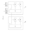
- Fig. 2 is a block diagram of the image forming system.
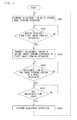
- Fig. 3 is a flow chart illustrating an operation of a first image forming apparatus performed by a first central processing unit (CPU).
- CPU central processing unit
- Fig. 4 is a flow chart illustrating an operation of a second image forming apparatus performed by a second CPU.
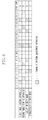
- Fig. 5 is a diagram illustrating timing for performing an adjustment operation of the image forming system according to an exemplary embodiment of the present invention.
- Fig. 6 is a diagram illustrating timing for performing an adjustment operation of the image forming system according to another exemplary embodiment of the present invention.
- Fig. 7 is a diagram illustrating timing for performing an adjustment operation of a conventional image forming system.
- Fig. 1 is a sectional view of an image forming system according to an exemplary embodiment of the present invention.
- the image forming system is configured by a first image forming apparatus 11 and a second image forming apparatus 21 being connected to each other.
- Each of the first image forming apparatus 11 and the second image forming apparatus 21 is a color image forming apparatus in which a plurality of image forming stations is installed adjacent to each other.
- An image reading apparatus 4 which reads a document image, and an operation unit 5, which receives an operation input from a user, are mounted on the first image forming apparatus 11. Moreover, a control unit 170, which controls the operation of each mechanism inside the apparatus, is mounted in the first image forming apparatus 11.
- Each image forming station has a similar configuration.
- Primary charging devices 112a to 112d, exposure devices 113a to 113d, and developing devices 114a to 114d are arranged opposite the outer circumferential surfaces of photosensitive drums 111a to 111d, which are driven to rotate in the arrow direction in Fig. 1 .
- the primary charging devices 112a to 112d provide charges of a uniform electrification amount to the surfaces of the photosensitive drums 111a to 111d.
- the exposure devices 113a to 113d scan a light beam such as a laser beam modulated according to an image signal by rotating a polygon mirror and form an electrostatic latent image by irradiating the photosensitive drums 111a to 111d with the light beam.
- the developing devices 114a to 114d houses developers (toner) of four colors of yellow (Y), magenta (M), cyan (C), and black (Bk), respectively, to develop each electrostatic latent image on the photosensitive drums 111a to 111d as a toner image.
- Cleaning devices 115a to 115d are mounted downstream of primary transfer areas 1Ta to 1Td, where developed toner images are transferred to an intermediate transfer belt 131.
- the cleaning devices 115a to 115d clean the surfaces of the photosensitive drums 111a to 111d by scraping away toner remaining on the photosensitive drums 111a to 111d.
- the intermediate transfer belt 131 is wound around a driving roller 132 that transmits a driving force, a tension roller 133 that provides a suitable tension to the intermediate transfer belt 131, and a secondary transfer internal roller 134, which is located opposite a secondary transfer area 1Te across the intermediate transfer belt 131.
- the driving roller 132 is driven to rotate by an intermediate transfer driving motor (not illustrated).
- a toner image formed on the photosensitive drum 111d most upstream in a rotation direction of the intermediate transfer belt 131 is primarily transferred to the intermediate transfer belt 131 in the primary transfer area 1Td by a primary transfer device 135d, to which a high voltage is applied. Then, the toner image primarily transferred onto the intermediate transfer belt 131 is conveyed to the next primary transfer area 1Tc, where the toner image on the photosensitive drum 111c is transferred by aligning with the toner image on the intermediate transfer belt 131.
- the same process is repeated to primarily transfer toner images of four colors onto the intermediate transfer belt 131.
- Recording paper P housed in a cassette 121 is sent out sheet by sheet by a pickup roller 122 and conveyed by a conveyance roller pair 123 along a feeding guide 124. Then, a skew correction of the recording paper P is made by causing the recording paper P to collide with a registration roller 125, whose rotation is stopped. The registration roller 125 then sends out the recording paper P to the secondary transfer area 1Te in accord with the timing of the toner image on the intermediate transfer belt 131. The toner image on the intermediate transfer belt 131 is then transferred onto the recording paper P in the secondary transfer area 1Te by a secondary transfer device 136, to which a high voltage is applied. In this manner, a toner image is transferred onto the front side (first surface) of the recording paper P.
- a cleaning device 150 which cleans an image forming surface of the intermediate transfer belt 131, is arranged downstream of the secondary transfer area 1Te in the rotation direction of the intermediate transfer belt 131.
- the cleaning device 150 includes a cleaner blade 151 and a waste toner box 152, which houses waste toner.
- the recording paper P that has passed through the secondary transfer area 1Te is guided to a fixing unit 140 by a conveyance guide 143.
- the fixing unit 140 includes a fixing roller 141a equipped with a heat source such as a halogen heater internally and a pressure roller 141b (this pressure roller may also be equipped with a heat source) pressed by the fixing roller 141a.
- the toner image on the recording paper P is fixed onto the recording paper P by heat and pressure from the fixing unit 140.
- the recording paper P conveyed from the fixing unit 140 is guided to a reverse conveying path 160 by a switching member 149 before being conveyed by an inverting roller 161. Then, the inverting roller 161 rotates in the opposite direction and the recording paper P is conveyed from the first image forming apparatus 11 to the second image forming apparatus 21 by an external discharging roller 145 while the recording paper P is reversed.
- the recording paper P conveyed to the second image forming apparatus 21 passes through a conveyance guide 224 before being conveyed up to a registration roller 225.
- a skew correction of the recording paper P is made by causing the recording paper P to collide with a registration roller 225, whose rotation is stopped.
- An intermediate transfer roller 231 has a toner image formed thereon through a process similar to that of the first image forming apparatus 11.
- the registration roller 225 then sends out the recording paper P to a secondary transfer area 2Te in accord with the timing of the toner image on the intermediate transfer belt 231.
- the toner image on the intermediate transfer belt 231 is then transferred onto the recording paper P in the secondary transfer area 2Te by a secondary transfer device 236, to which a high voltage is applied. In this manner, a toner image is transferred onto the back side (second surface) of the recording paper P.
- the recording paper P that has passed through the secondary transfer area 2Te is guided to a fixing unit 240 by a conveyance guide 243.
- the fixing unit 240 is configured similarly to the fixing unit 140 described above and performs a fixing operation by adding heat and pressure to the toner image on the recording paper P.
- the recording paper P conveyed from the fixing unit 240 is sent out to an internal discharging roller 244 before being discharged to a delivery tray 3 by an external discharging roller 245.
- a sensor 250 which detects delivery of the recording paper P, is mounted downstream of the external discharging roller 245. With the above procedure, images are formed on both sides of the recording paper P.
- Fig. 2 is a block diagram of the image forming system.
- a CPU 1 is a control circuit provided in the control unit 170 to control the whole first image forming apparatus 11.
- a read-only memory (ROM) 2 has a control program to control various kinds of processing performed by the first image forming apparatus 11 housed therein.
- a random access memory (RAM) 3 is a system work memory for the CPU 1 to operate and also functions as an image memory to temporarily store image data.
- the image reading apparatus 4, the operation unit 5, and a CPU 6 are also connected to the CPU 1.
- the CPU 6 is a control circuit provided in a control unit 270 to control the whole second image forming apparatus 21.
- a ROM 7 has a control program to control various kinds of processing performed by the second image forming apparatus 21 housed therein.
- a RAM 8 is a system work memory for the CPU 6 to operate and also functions as an image memory to temporarily store image data. The user can use an input key on the operation unit 5 to issue instructions of an image forming operation mode or switching of the display of the operation unit 5 to the CPU 1.
- the CPU 1 and the CPU 6 each perform an adjustment operation to stabilize image quality of output images output to recording paper in each image forming apparatus.
- An example of various adjustments made by the first image forming apparatus 11 and the second image forming apparatus 21 will be described below.
- image quality of images output to recording paper fluctuates due to property changes of members accompanying changes of the environment such as the temperature and humidity inside the apparatus or aged deterioration.
- the first image forming apparatus 11 and the second image forming apparatus 21 perform an adjustment operation at predetermined timing to stabilize image quality of images output to recording paper.
- the first image forming apparatus 11 and the second image forming apparatus 21 make a gradation correction. More specifically, the first image forming apparatus 11 and the second image forming apparatus 21 form a pattern image for gradation correction on an image bearing member, such as a photosensitive drum or intermediate transfer belt, to make a gradation correction based on data obtained by reading the pattern image. In addition, the first image forming apparatus 11 and the second image forming apparatus 21 also perform an adjustment operation to clean a wire of a charging device by moving a cleaner member periodically because electrifying characteristics are degraded if dirt or electrification products adhere to a charging wire of a primary charging device.
- Fig. 3 is a flow chart illustrating an operation of the first image forming apparatus 11 performed by the CPU 1.
- a program to execute the flow chart is stored in the ROM 2 and executed by being read by the CPU 1.
- step S301 the CPU 1 examines adjustment timing of the first image forming apparatus 11.
- the adjustment timing is individually set depending on the type of adjustment thereof.
- step S302 the CPU 1 makes an inquiry about the adjustment timing of the second image forming apparatus 21 at the second image forming apparatus 21 and, in step S303, waits until the adjustment timing is received.
- step S304 the CPU 1 calculates the adjustment timing of the image forming system as a whole based on the adjustment timing of the first image forming apparatus 11 and the adjustment timing of the second image forming apparatus 21. How to calculate the adjustment timing of the image forming system as a whole will be described below in detail.
- step S305 the CPU 1 notifies the second image forming apparatus 21 of the calculated adjustment timing of the image forming system as a whole.
- step S306 the CPU 1 determines whether the calculated adjustment timing of the image forming system as a whole has come. If the CPU 1 determines that the adjustment timing of the image forming system as a whole has come (YES in step S306), then in step S307, the CPU 1 performs an adjustment operation in the first image forming apparatus 11. When the adjustment operation is completed, the processing returns to step S301.
- Fig. 4 is a flow chart illustrating an operation of the second image forming apparatus 21 performed by the CPU 6.
- a program to execute the flow chart is stored in the ROM 7 and executed by being read by the CPU 6.
- step S401 the CPU 6 examines adjustment timing of the second image forming apparatus 21. Then, in step S402, the CPU 6 waits until an inquiry about the adjustment timing transmitted from the first image forming apparatus 11 in step S302 in Fig. 3 is received. After the inquiry about the adjustment timing being received from the first image forming apparatus 11, then in step S403, the CPU 6 transmits the adjustment timing of the second image forming apparatus 21 to the first image forming apparatus 11.
- step S404 the CPU 6 waits until the adjustment timing of the image forming system as a whole notified from the first image forming apparatus 11 in step S305 in Fig. 3 is received. After the adjustment timing of the image forming system as a whole being received, then in step S405, the CPU 6 determines whether the calculated adjustment timing of the image forming system as a whole has come. If the CPU 6 determines that the adjustment timing of the image forming system as a whole has come (YES in step S405), then in step S406, the CPU 6 performs an adjustment operation in the second image forming apparatus 21. When the adjustment operation is completed, the processing returns to step S401.
- Fig. 5 is a diagram illustrating timing for performing an adjustment operation of the image forming system according to the present embodiment.
- the adjustment timing is set six times for the first image forming apparatus and five times for the second image forming apparatus.
- the adjustment timing of each time comes according to circumstances of each image forming apparatus and thus comes at different times for the first image forming apparatus 11 and the second image forming apparatus 21.
- the adjustment timing for the second image forming apparatus 21 comes within a predetermined period from the adjustment timing for the first image forming apparatus 11, the adjustment timing is corrected so that the adjustment timing for the first image forming apparatus 11 and that for the second image forming apparatus 21 accord with each other.
- the adjustment timing is corrected so that the first image forming apparatus 11 and the second image forming apparatus 21 start an adjustment operation simultaneously.
- the adjustment timing may be corrected by correcting the adjustment timing for the first image forming apparatus or by correcting the adjustment timing for the first image forming apparatus.
- the adjustment timing of both the first image forming apparatus and that of the second image forming apparatus may be corrected.
- occurrences of downtime as a whole system can be reduced when an adjustment operation is performed so that lowering of productivity can be prevented.
- Fig. 6 is a diagram illustrating timing for performing an adjustment operation of the image forming system according to another exemplary embodiment of the present invention.
- the user can select one of a "quality priority mode” as a first mode and a “productivity priority mode” as a second mode via the operation unit 5.
- a “quality priority mode” is selected, the adjustment timing is corrected just like in Fig. 5 and when the "productivity priority mode” is selected, the frequency with which an adjustment operation is performed is further reduced by making a correction of further thinning out the adjustment timing.
- the user is allowed to make a selection between high image quality and productivity and if the user selects the "productivity priority mode", a further reduction of downtime can be realized.
Landscapes
- Physics & Mathematics (AREA)
- General Physics & Mathematics (AREA)
- Engineering & Computer Science (AREA)
- Microelectronics & Electronic Packaging (AREA)
- Control Or Security For Electrophotography (AREA)
- Accessory Devices And Overall Control Thereof (AREA)
- Counters In Electrophotography And Two-Sided Copying (AREA)
- Printers Characterized By Their Purpose (AREA)
Applications Claiming Priority (1)
| Application Number | Priority Date | Filing Date | Title |
|---|---|---|---|
| JP2009288469A JP2011128464A (ja) | 2009-12-18 | 2009-12-18 | 画像形成システム |
Publications (2)
| Publication Number | Publication Date |
|---|---|
| EP2336831A2 true EP2336831A2 (de) | 2011-06-22 |
| EP2336831A3 EP2336831A3 (de) | 2014-07-30 |
Family
ID=43827854
Family Applications (1)
| Application Number | Title | Priority Date | Filing Date |
|---|---|---|---|
| EP10192793.7A Withdrawn EP2336831A3 (de) | 2009-12-18 | 2010-11-26 | Bilderzeugungssystem mit erster und zweiter Bilderzeugungsvorrichtung |
Country Status (5)
| Country | Link |
|---|---|
| US (1) | US8494392B2 (de) |
| EP (1) | EP2336831A3 (de) |
| JP (1) | JP2011128464A (de) |
| KR (1) | KR101259707B1 (de) |
| CN (1) | CN102103351B (de) |
Families Citing this family (9)
| Publication number | Priority date | Publication date | Assignee | Title |
|---|---|---|---|---|
| JP5585326B2 (ja) * | 2010-09-09 | 2014-09-10 | コニカミノルタ株式会社 | 画像形成システム |
| JP5744452B2 (ja) * | 2010-09-22 | 2015-07-08 | キヤノン株式会社 | 画像形成システム |
| JP5621802B2 (ja) * | 2012-03-13 | 2014-11-12 | コニカミノルタ株式会社 | 画像形成システム及び画像形成システムの制御方法 |
| JP2017156819A (ja) * | 2016-02-29 | 2017-09-07 | キヤノン株式会社 | 管理システム、代替管理装置、管理方法、及びプログラム |
| JP6658106B2 (ja) * | 2016-03-01 | 2020-03-04 | コニカミノルタ株式会社 | 画像形成装置、画像形成方法、画像形成管理装置および制御プログラム |
| JP6772817B2 (ja) * | 2016-12-19 | 2020-10-21 | コニカミノルタ株式会社 | 画像形成システム |
| JP6852475B2 (ja) * | 2017-03-13 | 2021-03-31 | コニカミノルタ株式会社 | 画像形成システム、画像形成方法および装置、ジョブ管理方法およびジョブ管理プログラム |
| JP7172225B2 (ja) * | 2018-07-20 | 2022-11-16 | 富士フイルムビジネスイノベーション株式会社 | 画像形成システム |
| JP2024111507A (ja) * | 2023-02-06 | 2024-08-19 | キヤノン株式会社 | 画像読取装置 |
Citations (2)
| Publication number | Priority date | Publication date | Assignee | Title |
|---|---|---|---|---|
| JPH06148992A (ja) | 1992-11-06 | 1994-05-27 | Matsushita Electric Ind Co Ltd | 電子写真装置 |
| JP2004268572A (ja) | 2003-02-21 | 2004-09-30 | Fuji Xerox Co Ltd | 重連印刷装置および重連印刷方法 |
Family Cites Families (30)
| Publication number | Priority date | Publication date | Assignee | Title |
|---|---|---|---|---|
| US4958187A (en) * | 1987-02-13 | 1990-09-18 | Canon Kabushiki Kaisha | Image forming apparatus for scanning both sides of an original and producing a duplex copy |
| JPH10133445A (ja) * | 1996-11-05 | 1998-05-22 | Canon Inc | 画像記録装置 |
| JPH10142857A (ja) * | 1996-11-08 | 1998-05-29 | Ricoh Co Ltd | 画像形成装置 |
| JPH1138845A (ja) * | 1997-07-14 | 1999-02-12 | Minolta Co Ltd | 画像形成システム |
| JPH11160951A (ja) | 1997-12-01 | 1999-06-18 | Konica Corp | 両面カラー画像形成装置 |
| JP3807080B2 (ja) * | 1998-02-23 | 2006-08-09 | コニカミノルタビジネステクノロジーズ株式会社 | 画像補正装置及びそのプログラムソフトの記憶媒体 |
| JP3824037B2 (ja) | 1998-03-06 | 2006-09-20 | リコープリンティングシステムズ株式会社 | 電子写真印刷装置の転写制御方法 |
| US6032014A (en) * | 1998-07-14 | 2000-02-29 | Xeikon Nv | Method of using an image forming apparatus |
| DE10142326B4 (de) * | 2001-08-30 | 2004-09-02 | Océ Priting Systems GmbH | Drucksystem aus meheren elektrofotografischen Druckgeräten, die nacheinander einen bandförmigen Aufzeichnungsträger bedrucken. |
| US6493517B1 (en) * | 2001-09-10 | 2002-12-10 | Hewlett-Packard Company | Integration of self-determined consumable usage model in pigmentation material low/out forecast |
| US6608988B2 (en) * | 2001-10-18 | 2003-08-19 | Xerox Corporation | Constant inverter speed timing method and apparatus for duplex sheets in a tandem printer |
| JP2003319112A (ja) * | 2002-04-24 | 2003-11-07 | Ricoh Co Ltd | 画像形成装置 |
| JP4419451B2 (ja) * | 2003-06-20 | 2010-02-24 | コニカミノルタビジネステクノロジーズ株式会社 | タンデム画像形成システム |
| JP2005266686A (ja) * | 2004-03-22 | 2005-09-29 | Canon Inc | 画像形成装置 |
| US7123873B2 (en) * | 2004-08-23 | 2006-10-17 | Xerox Corporation | Printing system with inverter disposed for media velocity buffering and registration |
| US7245856B2 (en) * | 2004-11-30 | 2007-07-17 | Xerox Corporation | Systems and methods for reducing image registration errors |
| JP2007038503A (ja) * | 2005-08-02 | 2007-02-15 | Canon Inc | 画像形成装置及びその制御方法 |
| JP2007083465A (ja) * | 2005-09-21 | 2007-04-05 | Sharp Corp | 画像記録システム |
| JP4735850B2 (ja) * | 2006-11-28 | 2011-07-27 | 富士ゼロックス株式会社 | 消耗品管理装置、画像形成装置及びプログラム |
| JP2009008801A (ja) * | 2007-06-27 | 2009-01-15 | Konica Minolta Business Technologies Inc | 画像形成装置 |
| US8099009B2 (en) * | 2008-05-23 | 2012-01-17 | Eastman Kodak Company | Method for print engine synchronization |
| US8180242B2 (en) * | 2008-05-23 | 2012-05-15 | Eastman Kodak Company | Print engine synchronization system and apparatus |
| US8000645B2 (en) | 2008-05-29 | 2011-08-16 | Eastman Kodak Company | Print engine productivity module inverter |
| US8355159B2 (en) * | 2009-05-19 | 2013-01-15 | Eastman Kodak Company | Print engine speed compensation |
| US20100296823A1 (en) * | 2009-05-19 | 2010-11-25 | Dobbertin Michael T | Dual engine synchronization |
| US8427705B2 (en) * | 2009-05-22 | 2013-04-23 | Eastman Kodak Company | Maximizing speed tolerance during dual engine synchronization |
| US8213821B2 (en) * | 2009-05-22 | 2012-07-03 | Eastman Kodak Company | Engine synchronization with a small delta time between engines |
| JP2010284884A (ja) * | 2009-06-11 | 2010-12-24 | Ricoh Co Ltd | 連続紙両面印刷システム |
| JP2011069980A (ja) * | 2009-09-25 | 2011-04-07 | Canon Inc | 画像形成システム |
| JP5609568B2 (ja) * | 2010-11-11 | 2014-10-22 | コニカミノルタ株式会社 | 画像形成システム |
-
2009
- 2009-12-18 JP JP2009288469A patent/JP2011128464A/ja active Pending
-
2010
- 2010-11-26 EP EP10192793.7A patent/EP2336831A3/de not_active Withdrawn
- 2010-12-07 KR KR1020100124465A patent/KR101259707B1/ko active Active
- 2010-12-13 US US12/966,780 patent/US8494392B2/en not_active Expired - Fee Related
- 2010-12-14 CN CN201010599775.7A patent/CN102103351B/zh active Active
Patent Citations (2)
| Publication number | Priority date | Publication date | Assignee | Title |
|---|---|---|---|---|
| JPH06148992A (ja) | 1992-11-06 | 1994-05-27 | Matsushita Electric Ind Co Ltd | 電子写真装置 |
| JP2004268572A (ja) | 2003-02-21 | 2004-09-30 | Fuji Xerox Co Ltd | 重連印刷装置および重連印刷方法 |
Also Published As
| Publication number | Publication date |
|---|---|
| KR101259707B1 (ko) | 2013-05-06 |
| CN102103351B (zh) | 2013-07-17 |
| US8494392B2 (en) | 2013-07-23 |
| CN102103351A (zh) | 2011-06-22 |
| EP2336831A3 (de) | 2014-07-30 |
| KR20110070787A (ko) | 2011-06-24 |
| US20110150520A1 (en) | 2011-06-23 |
| JP2011128464A (ja) | 2011-06-30 |
Similar Documents
| Publication | Publication Date | Title |
|---|---|---|
| EP2336831A2 (de) | Bilderzeugungssystem mit erster und zweiter Bilderzeugungsvorrichtung | |
| JP4613949B2 (ja) | 画像形成装置 | |
| JP4600498B2 (ja) | 画像形成装置及び画像色ずれ補正方法 | |
| JP2011069980A (ja) | 画像形成システム | |
| JP2007072294A (ja) | 画像形成装置、画像形成装置の制御方法 | |
| JP2010091925A (ja) | 画像形成装置 | |
| JP2012208171A (ja) | 画像形成装置 | |
| JP7061279B2 (ja) | 画像読取装置、及び画像形成装置 | |
| JP2018194654A (ja) | 画像形成装置 | |
| CN106814561B (zh) | 图像形成装置 | |
| JP4458301B2 (ja) | 画像形成装置 | |
| JP5618585B2 (ja) | 画像形成装置 | |
| JP5853634B2 (ja) | 画像処理装置、画像処理方法およびプログラム | |
| JP5060094B2 (ja) | 画像形成装置 | |
| JP6776829B2 (ja) | デカーラー、用紙後処理装置、及び画像形成装置 | |
| US7471912B2 (en) | Image forming apparatus including intermediate transfer member and method of controlling the same | |
| JP2019082575A (ja) | 画像形成装置及び情報処理装置 | |
| JP5049471B2 (ja) | 画像形成装置 | |
| JP4442686B2 (ja) | 画像形成装置 | |
| JP5800219B2 (ja) | 画像形成装置 | |
| JP4904208B2 (ja) | 画像形成装置及びプログラム | |
| JP2009151185A (ja) | 画像形成装置 | |
| JP2006208668A (ja) | 画像形成装置 | |
| US20120069129A1 (en) | Image forming apparatus and image forming method | |
| JP5506532B2 (ja) | 画像形成装置及び像担持体の相対位相ずれの補正方法 |
Legal Events
| Date | Code | Title | Description |
|---|---|---|---|
| PUAI | Public reference made under article 153(3) epc to a published international application that has entered the european phase |
Free format text: ORIGINAL CODE: 0009012 |
|
| AK | Designated contracting states |
Kind code of ref document: A2 Designated state(s): AL AT BE BG CH CY CZ DE DK EE ES FI FR GB GR HR HU IE IS IT LI LT LU LV MC MK MT NL NO PL PT RO RS SE SI SK SM TR |
|
| AX | Request for extension of the european patent |
Extension state: BA ME |
|
| PUAL | Search report despatched |
Free format text: ORIGINAL CODE: 0009013 |
|
| AK | Designated contracting states |
Kind code of ref document: A3 Designated state(s): AL AT BE BG CH CY CZ DE DK EE ES FI FR GB GR HR HU IE IS IT LI LT LU LV MC MK MT NL NO PL PT RO RS SE SI SK SM TR |
|
| AX | Request for extension of the european patent |
Extension state: BA ME |
|
| RIC1 | Information provided on ipc code assigned before grant |
Ipc: G03G 15/23 20060101ALI20140626BHEP Ipc: G03G 15/00 20060101AFI20140626BHEP |
|
| STAA | Information on the status of an ep patent application or granted ep patent |
Free format text: STATUS: THE APPLICATION HAS BEEN WITHDRAWN |
|
| 18W | Application withdrawn |
Effective date: 20141124 |