EP2297433B1 - Ventiltriebvorrichtung - Google Patents
Ventiltriebvorrichtung Download PDFInfo
- Publication number
- EP2297433B1 EP2297433B1 EP09765531A EP09765531A EP2297433B1 EP 2297433 B1 EP2297433 B1 EP 2297433B1 EP 09765531 A EP09765531 A EP 09765531A EP 09765531 A EP09765531 A EP 09765531A EP 2297433 B1 EP2297433 B1 EP 2297433B1
- Authority
- EP
- European Patent Office
- Prior art keywords
- shifting
- switching
- cam
- gate
- segments
- Prior art date
- Legal status (The legal status is an assumption and is not a legal conclusion. Google has not performed a legal analysis and makes no representation as to the accuracy of the status listed.)
- Active
Links
Images


Classifications
-
- F—MECHANICAL ENGINEERING; LIGHTING; HEATING; WEAPONS; BLASTING
- F01—MACHINES OR ENGINES IN GENERAL; ENGINE PLANTS IN GENERAL; STEAM ENGINES
- F01L—CYCLICALLY OPERATING VALVES FOR MACHINES OR ENGINES
- F01L13/00—Modifications of valve-gear to facilitate reversing, braking, starting, changing compression ratio, or other specific operations
- F01L13/0015—Modifications of valve-gear to facilitate reversing, braking, starting, changing compression ratio, or other specific operations for optimising engine performances by modifying valve lift according to various working parameters, e.g. rotational speed, load, torque
- F01L13/0036—Modifications of valve-gear to facilitate reversing, braking, starting, changing compression ratio, or other specific operations for optimising engine performances by modifying valve lift according to various working parameters, e.g. rotational speed, load, torque the valves being driven by two or more cams with different shape, size or timing or a single cam profiled in axial and radial direction
- F01L2013/0052—Modifications of valve-gear to facilitate reversing, braking, starting, changing compression ratio, or other specific operations for optimising engine performances by modifying valve lift according to various working parameters, e.g. rotational speed, load, torque the valves being driven by two or more cams with different shape, size or timing or a single cam profiled in axial and radial direction with cams provided on an axially slidable sleeve
Definitions
- the invention relates to a valve drive device according to the preamble of claim 1.
- the invention is in particular the object of providing a valve drive device with a high flexibility. It is achieved according to the invention by the features of claim 1. Further embodiments emerge from the subclaims.
- the invention relates to a valve drive device, in particular an internal combustion engine, with an actuating device which is provided to displace at least a first axially displaceable cam element by means of a shift gate.
- the actuating device is provided to switch the first cam element in at least three switching positions.
- a valve drive device can be realized, which has a high flexibility due to a high number of switching positions and thus can be easily adapted to different operating modes of the internal combustion engine, in particular different Brenn Anlagensmodi.
- a "switching position” is to be understood in particular as meaning a switching position of the cam element, which in particular can be assigned a defined cam lift.
- the valve drive device has a plurality of cam elements, “identical shift positions” should be understood to mean, in particular, that the cam elements have the same valve lift.
- the cam member has at least one cam set with at least three sub-cams, wherein advantageously each sub-cam a shift position and each cam set is assigned to a gas exchange valve.
- the actuating device is provided to switch a zero stroke, a partial stroke and / or a full stroke.
- a valve drive device which can switch such switching positions, is particularly advantageous since it can easily increase the efficiency of the internal combustion engine, in particular of an internal combustion engine for a passenger car.
- a zero stroke is to be understood as meaning a cam lift of zero.
- a "partial stroke” is to be understood in particular as a cam lift, which is smaller than a cam lift of the full stroke.
- the shift gate has at least two switching segments, which are intended to move the first cam element in a switching direction.
- the switching direction is formed as a first switching direction and it is proposed that the shift gate has at least two further switching segments, which are intended to switch the cam element in a second switching direction, wherein the second switching direction is preferably opposite to the first switching direction.
- the switching segments are assigned for the first switching direction of a first slide track of the shift gate. It is further proposed that the two further switching segments for the second switching direction of a second link path of the shift gate are assigned.
- the shift gate on at least two other switching segments, which are intended to move a second cam member in the switching direction.
- a second cam element can also be moved into three switching positions.
- the shift gate has two further switching segments, which are arranged in the second slide track and which are intended to move the second cam member in the second switching direction.
- the shift gate has the two slide tracks, each having four of the switching segments, wherein preferably the switching segments of a slide track are associated with a switching direction.
- the switching segments of a slide track are alternately assigned to the cam elements.
- the shift gate is provided to sequentially shift the first cam element and the second cam element.
- the actuating device has a reset unit, which is intended to end a switching operation.
- a switching operation can be ended at a defined time, whereby a high number of possible combinations of the switching position can be achieved simply by means of the switching segments.
- terminatate is meant in this context, in particular a premature termination before an end of the shift gate, in particular an interruption or a cancel.
- a “switching operation” is to be understood in particular as a displacement of the cam element, wherein in the case of a plurality of cam elements a “switching operation” is to be understood as meaning, in particular, a displacement of one of the cam elements.
- the reset unit is provided to end the switching process immediately after a displacement of the first cam member.
- the first cam element can thereby be displaced at least partially independently of the second cam element.
- the reset unit is provided to the switching operation after a move of the second cam element to finish.
- the second cam element can thereby be displaced at least partially independently of the first cam element.
- the reset unit has at least one switching unit with a switching element, which is intended to be moved by means of an actuator in a neutral position.
- the switching process can be completed easily and in particular independently of the shift gate.
- the shift gate has at least one intermediate segment, which is intended to end the switching operation.
- the switching operation can likewise be terminated simply and in particular independently of switching units of the actuating device by means of which the cam elements are displaced.
- FIG. 1 and FIG. 2 show an actuator 10a of a valve drive device.
- the actuating device 10a is provided to move two cam elements 11a, 12a, which are arranged to be axially displaceable and rotationally fixed on a base camshaft 35a.
- the actuating device 10a has a first and a second switching unit 23a, 24a, which can displace the cam elements 11a, 12a by means of a shifting gate 13a.
- the shift gate 13a has a first slide track 36a and a second slide tracks 37a.
- the slide tracks 36a, 37a by means of which the cam elements 11a, 12a are displaced, are designed as groove-shaped depressions and are introduced directly into the cam elements 11a, 12a.
- the cam members 11a, 12a are L-shaped and axially overlapping in an area where they abut each other.
- In the circumferential direction takes in the region of the guide tracks 36a, 37a each cam member 11a, 12a a rotation angle of 180 ° degrees.
- the slide tracks 36a, 37a which extend over a rotation angle greater than 360 ° degrees, are each arranged in part on the cam member 11a and partly on the cam member 12a.
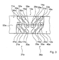
- Both slide tracks 36a, 37a have a basic shape with a quadruple S-shaped structure (cf. Fig. 3 ). Both slide tracks 36a, 37a each have a single track segment 38a, 39a, four shift segments 14a-21a, three intermediate segments 29a-34a and a Ausspursegment 40a, 41a.
- the switching segments 14a, 16a, 18a, 20a of the first slide track 36a have an axial directional component that corresponds to a first shift direction is opposite, whereby by means of the switching segments 14a, 16a, 18a, 20a and a rotational movement of the cam member 11a, an axial force for switching in the first switching direction can be generated.
- the switching segments 15a, 17a, 19a, 21a of the second cam track 37a have an axial direction component which is directed axially opposite to a second switching direction, whereby an axial force for switching in the second switching direction can be generated analogously.
- the first slide track 36a alternately one of the shift segments 14a, 16a, 18a, 20a and one of the intermediate segments 29a, 31a, 33a are arranged following the single track segment 38a, the switch segment 14a following directly on the single track segment 38a.
- the Ausspursegment 40a is arranged.
- the single track segment 38a has an increasing radial depth.
- the intermediate segments 29a, 31a, 33a and the switching segments 14a, 16a, 18a, 20a have a constant radial depth.
- the Ausspursegment 40a has a decreasing radial depth. Due to the decreasing radial depth of the Ausspursegments 40a, the switching element 25a of the switching unit 23a is moved back to its neutral position in which it is out of engagement with the shift gate 13a back.
- the single track segment 38a, the intermediate segments 29a, 31a, 33a and the Ausspursegment 40a are each arranged in part on the cam member 11a and partially on the cam member 12a.
- the switching segments 14a, 16a, 18a, 20a are each completely arranged on one of the cam elements 11a, 12a, wherein successive switching segments 14a, 16a, 18a, 20a are arranged alternately on the cam elements 11a, 12a.
- the switching segment 14a and the switching segment 18a are provided to displace the cam member 11a.
- the switching segment 16a and the switching segment 20a are provided to displace the cam member 12a.
- the second slide track 37a is formed analogously to the first slide track 36a. Subsequent to the Einspursegment 39a also alternately one of the switching segments 15a, 17a, 19a, 21a and one of the intermediate segments 30a, 32a, 34a are arranged. On the last switching segment 21 a immediately follows the Ausspursegment 41 a.
- the Einspursegment 39 a, the intermediate segments 30 a, 32 a, 34 a and the Ausspursegment 41 a are each arranged in part on the cam member 11 a and partially on the cam member 12 a.
- the switching segments 15a, 17a, 19a, 21a are each completely arranged on one of the cam elements 11a, 12a, wherein successive switching segments 15a 17a, 19a, 21a are alternately arranged on the cam elements 11a, 12a, which they can move.
- the switching segments 14a-21a are three different switching positions of the cam elements 11a, 12a switchable (see. Fig. 4 ).
- the cam element 11a and the cam element 12a each have at least one cam unit 43a, 47a with three partial cams 44a-46a, 48a-50a.
- the partial cams 44a-46a, 48a-50a have a different lifting height and are assigned to the switching positions of the cam elements 11a, 12a.
- the partial cams 44a, 48a with the highest lifting height are assigned to the switching positions with a full stroke.
- the partial cams 45a, 49a with a medium lifting height are assigned to the switching positions with a partial stroke.
- the partial cams 46a, 50a with the lowest lifting height which is advantageously equal to zero, are assigned to the switching positions with a zero stroke.
- the highest lift part cams 44a, 48a and the lowest lift lift partial cams 46a, 50a are disposed outboard in the respective cam units 43a, 47a.
- the partial cams 45a, 49a with the medium lift height are arranged between the other partial cams 44a, 46a, 48a, 50a of the corresponding cam unit 43a, 47a.
- the actuating device 10a has the two switching units 23a, 24a.
- the first switching unit 23a has a first actuator 27a and a first switching element 25a.
- the switching element 25a is partially formed as a switching pin 51a, which is extended in a switching position of the first switching element 25a. In the switching position, the shift pin 51a engages in the first slide track 36a of the shift gate 13a.
- the cam elements 11a, 12a can be moved in the first switching direction.
- the second switching unit 24a has a second actuator 28a and a second switching element 26a.
- the second switching element 26a is also partially formed as a switching pin 52a, which is extended in a switching position of the second switching element 26a. In a switching position, the switching pin 52a engages in a second slide track 37a of the shift gate 13a.
- the cam elements 11a, 12a can be moved in the second, the first switching direction opposite switching direction.
- the cam elements 11a, 12a are partially coupled in terms of motion technology via the shift gate 13a.
- the cam elements 11a, 12a can be displaced sequentially.
- the cam elements 11a, 12a are thereby displaced as a function of a rotation angle of the base camshaft 35a or of the cam elements 11a, 12a.
- first the first cam member 11a is displaced, and subsequently, when the first cam member 11a is completely shifted, the second cam member 12a is displaced.
- the second cam element 12a In the second switching direction, first the second cam element 12a and then the first cam element 11a is displaced.
- the cam elements 11a, 12a are always displaced in a base circle phase of their cam units 43a, 47a.
- the first cam member 11 a is made in two parts and has two cam member parts 53 a, 54 a, which are arranged on both sides of the cam member 12 a.
- the cam members 53a, 54a are fixedly connected to each other by means of an inner coupling rod 55a for axial movement. In principle, it is also conceivable to arrange the two cam element parts 53a, 54a adjacent and to make them in one piece.
- the first actuator 27a which moves the first switching element 25a, has a solenoid unit 56a.
- the solenoid unit 56a includes a coil 57a disposed in a stator 58a of the solenoid unit 56a.
- a magnetic field can be generated, which interacts with a permanent magnet 59a, which is arranged in the switching element 25a.
- the switching element 25a can be extended with the switching pin 51a.
- a core 60a amplifies the magnetic field generated by the solenoid unit 56a.
- the permanent magnet 59a interacts with the surrounding material.
- the permanent magnet 59a interacts with the core 60a of the solenoid unit 56a, which is made of a magnetizable material.
- the permanent magnet 59a interacts with the stator 58a of the actuator 27a.
- the permanent magnet 59a stabilizes the switching element 25a in the switching position, or the neutral position.
- the permanent magnet 59a interacts with the field of the solenoid unit 56a.
- an attractive force and a repulsive force can be realized.
- a polarization The solenoid unit 56a can be changed by means of a current direction with which the solenoid unit 56a is energized.
- the electromagnet unit 56a is energized in the current direction in which the repulsive force arises between the electromagnet unit 56a and the permanent magnet 59a.
- a spring unit 61 a is arranged in the actuator 27 a, which also exerts a force on the switching element 25 a.
- the force of the spring unit 61a is directed in a direction corresponding to a direction of the repulsive force between the solenoid unit 56a and the permanent magnet 59a, thereby accelerating an extension operation of the switching member 25a.
- the second actuator 28a is constructed analogously to the first actuator 27a. It comprises a solenoid unit 62a, which has a coil 63a, arranged in the stator 58a, which is jointly designed for both actuators 27a, 28a, with a magnetisable core 64a, which interacts with a permanent magnet 65a arranged in the switching element 26a and can extend the switching pin 52a. An extension operation is also accelerated in the actuator 28a by a spring unit 66a.
- the two actuators are arranged in a common base housing part 67a, which at the same time forms the integrally formed stator 58a of the actuators 27a, 28a.
- the coils 57a 63a of the actuators 27a, 28a are also wound around the base housing part 67a.
- another housing part 68a is connected to the basic housing part 67a.
- the further housing part 68a encloses both actuators 27a, 28a.
- the housing part 68a guides for the switching elements 25a, 26a.
- the actuating device 10a has a coupling element 69a, by means of which the first switching element 25a and the second switching element 26a are coupled with each other in terms of movement ( see. Fig. 1 and Fig. 2 ).
- the coupling element 69a couples the two switching elements 25a, 26a complementary to each other.
- the second switching element 26a can be moved by means of the first actuator 27a and the first switching element 25a by means of the second actuator 28a in the neutral position.
- the coupling element 69a thus forms part of a reset unit 22a, by means of which the switching elements 25a, 26a can be returned to their neutral positions and thus a switching operation can be terminated prematurely.
- the coupling element 69a is rotatably mounted between the switching elements 25a, 26a.
- the two switching elements 25a, 26a each have a recess 70a, 71a into which the coupling element 69a engages.
- the recesses 70a, 71a By means of the recesses 70a, 71a, the switching elements 25a, 26a are connected to each other in terms of motion.
- the coupling element 69a thereby provides a rocking mechanism which couples the switching elements 25a, 26a in a complementary manner.
- the second switching element 26a is moved by means of the first actuator 27a in the neutral position by the first switching element 25a is moved to the switching position.
- the first switching element 25a is moved by means of the second actuator 28a in the neutral position by the second switching element 26a is moved to the switching position.
- both switching elements 25a, 26a can be moved back into the basic position by means of the Ausspursegmente 40a, 41a.
- the actuator 27a, 28a of the switching element 25a, 26a which is to be moved into the neutral position, additionally energized in the current direction in which the solenoid unit 56a, 62a exerts an attractive force and the movement of the switching element 25a, 26a supported in the neutral position.
- the cam member 11a can be switched to the switching position with partial stroke and the cam member 12a in the switching position with zero stroke. If both cam elements 11a, 12a are in the switching position with zero stroke, the switching element 25a of the first switching unit 23a is extended and engages in the first slide track 36a.
- the cam member 11a is moved from the switching position with zero stroke in the switching position with partial stroke.
- the switching element 26a of the second switching unit 24a is extended.
- the second switching element 26a spurts into the Ausspursegment 41a of the second slide track 37a.
- the switching element 25a of the first switching unit 23a is moved back to the neutral position.
- the switching element 26a of the second switching unit 24a is moved back by the Ausspursegment 41 a in its neutral position.
- FIGS. 5 to 8 a further embodiment of the invention is shown. To distinguish the embodiments, the letter a in the reference numerals of the embodiment in the FIGS. 1 to 4 by the letter b in the reference numerals of the embodiment in the FIGS. 5 to 8 replaced. In the following description can be made to the description of the embodiment in the. Constant components, features and functions FIGS. 1 to 4 to get expelled.
- FIG. 5 shows a further embodiment of a shift gate 13b of an actuator 10b of a valve drive device.
- the actuating device 10b is provided to move two cam elements 11b, 12b, which are axially displaceable and rotationally fixed on a base camshaft 35b.
- the actuating device 10b has a first switching unit 23b and a second switching unit 24b, which can shift the cam elements 11b, 12b by means of the shifting gate 13b.
- the shift gate 13b has a first slide track 36b and a second slide tracks 37b.
- the slide tracks 36b, 37b by means of which the cam elements 11b, 12b can be moved, are designed as groove-shaped depressions and introduced directly into the cam elements 11b, 12b.
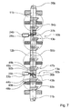
- the cam members 11b, 12b are L-shaped and axially overlapping in an area where they abut each other (see FIG. Fig. 7 ).
- In the circumferential direction takes in the region of the guide tracks 36b, 37b each cam member 11b, 12b, a rotation angle of 180 ° degrees.
- the slide tracks 36b, 37b which extend over a rotational angle greater than 360 ° degrees, are arranged in each case partly on the cam element 11b and partly on the cam element 12b.
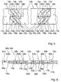
- Both slide tracks 36b, 37b have a basic shape with a quadruple S-shaped structure (cf. Fig. 5 ). Both slide tracks 36b, 37b each have a single track segment 38b, 39b, four shift segments 14b-21b, three intermediate segments 29b-34b and a trip segment 40b, 41b.
- the switching segments 14b, 16b, 18b, 20b of the first slide track 36b have an axial direction component, which is opposite to a first switching direction, whereby by means of the switching segments 14b, 16b, 18b, 20b and a Rotary movement of the cam elements 11b, 12b, an axial force for switching in the first switching direction can be generated.
- the switching segments 15b, 17b, 19b, 21b of the second link path 37b have an axial direction component which is directed axially opposite to a second switching direction, whereby an axial force for switching in the second switching direction can be generated analogously.
- the switching segments 14b, 16b, 18b, 20b and one of the intermediate segments 29b, 31b, 33b are arranged following the single track segment 38b, the switching segment 14b immediately following the single track segment 38b.
- the Ausspursegment 40b is arranged.
- the single track segment 38b has an increasing radial depth.
- the switching segments 14b, 16b, 18b, 20b have a constant radial depth.
- the Ausspursegment 40b has a decreasing radial depth. Due to the decreasing radial depth of the Ausspursegments 40b, a switching element 25b of the first switching unit 23b is moved back to its neutral position in which it is out of engagement with the shift gate 13b.
- the one-track segment 38b, the intermediate segments 29b, 31b, 33b, and the split-out segment 40b are respectively disposed in part on the cam member 11b and partly on the cam member 12b.
- the switching segments 14b, 16b, 18b, 20b are each completely arranged on one of the cam elements 11b, 12b, wherein successive switching segments 14b, 16b, 18b, 20b are arranged alternately on the cam elements 11b, 12b.
- the switching segment 14b and the switching segment 18b are provided to displace the cam member 11b.
- the switching segment 16b and the switching segment 20b are provided to displace the cam member 12b.
- the second slide track 37b is formed analogously to the first slide track 36b. Subsequent to the Einspursegment 29b also alternately one of the switching segments 15b, 17b, 19b, 21b and one of the intermediate segments 30b, 32b, 34b are arranged. The last switching segment 21b is immediately followed by the Ausspursegment 41b.
- the one-track segment 38b, the intermediate segments 30b, 32b, 34b, and the split-out segment 41b are respectively disposed in part on the cam member 11b and partly on the cam member 12b.
- the switching segments 15b, 17b, 19b, 21b are each completely arranged on one of the cam elements 11b, 12b, wherein successive switching segments 15b, 17b, 19b, 21b are alternately arranged on the cam members 11b, 12b which they can displace.
- the cam element 11bb and the cam element 12b each have at least one cam unit 43b, 47b with three partial cams 44b-46b, 48b-50b.
- the partial cams 44b-46b, 48b-50b have a different lifting height and are shift positions of the cam elements 11b, 12b assignable.
- the partial cams 44b, 48b with the highest lifting height are associated with switch positions with a full stroke.
- the partial cams 45b, 49b with a medium lifting height are associated with switching positions with a partial stroke.
- the partial cams 46b, 50b with the lowest lifting height which is advantageously equal to zero, are associated with switching positions with a zero stroke.
- the highest lift part cams 44b, 48b and the lowest lift lift partial cams 46b, 50b are disposed outwardly in the respective cam units 43b, 47b.
- the intermediate cam partial cams 45b, 49b are disposed between the other partial cams 44b, 46b, 48b, 50b of the corresponding cam unit 43b, 47b.
- the actuating device has the two switching units 23b, 24b.
- the first switching unit 23b has a first actuator 27b and a first switching element 25b.
- the switching element 25b is partially formed as a switching pin 51b, which is extended in a switching position of the first switching element 25b. In the switching position, the shift pin 51b engages in the first slide track 36b of the shift gate 13b.
- the cam elements 11b, 12b can be moved in the first switching direction.
- the first actuator 27b which moves the first switching element 25b, has a solenoid unit 56b.
- the solenoid unit 56b includes a coil 57b disposed in a stator 58b of the solenoid unit 56b.
- a magnetic field can be generated, which interacts with a permanent magnet 59b, which is arranged in the switching element 25b.
- the switching element 25b can be extended with the switching pin 51b.
- a core 60b amplifies the magnetic field generated by the solenoid unit 56b.
- the permanent magnet 59b When the coil 57b is deenergized, the permanent magnet 59b interacts with the surrounding material. In the neutral position, the permanent magnet 59b interacts with the core 60b of the solenoid unit 59b, which is made of a magnetizable material. In the switching position, the permanent magnet 59b interacts with the stator 58b of the actuator 27b. In a de-energized operating state, the permanent magnet 59b stabilizes the switching element 25b in the switching position, or the neutral position.
- the permanent magnet 59b interacts with the field of the solenoid unit 56b.
- an attractive force and a repulsive force can be realized.
- a polarization of the solenoid unit 56b can be changed by means of a current direction, with which the solenoid unit 56b is energized.
- the electromagnet unit 56b is energized in the current direction in which the repulsive force arises between the electromagnet unit 56b and the permanent magnet 59b.
- a spring unit 61b is arranged, which also exerts a force on the switching element 25b.
- the force of the spring unit 61b is directed in a direction corresponding to a direction of the repulsive force between the solenoid unit 56b and the permanent magnet 59b, thereby accelerating an extension operation of the switching element 25b.
- the second switching unit 24b is designed analogously to the first switching unit 23b.
- the second switching unit 23b has a switching pin 52b, which engages in the switching path 36b in a switching position of the switching element 25b.
- the cam elements 11b, 12b are displaced in the second, the first switching direction opposite switching direction.
- the cam elements 11b, 12b are partially coupled in terms of motion technology via the shift gate 13b.
- the actuating device 10b By means of the actuating device 10b, the cam elements 11b, 12b can be displaced sequentially.
- the cam elements 11b, 12b are displaced in response to a rotation angle of the base camshaft 35b. In the first shift direction, first, the cam member 11b is displaced, and subsequently, when the cam member 11b is completely shifted, the cam member becomes 12b moved. In the second switching direction, first the cam element 12b and then the cam element 11b is displaced.
- the cam element 11b is designed in two parts and has two cam element parts 53b, 54b, which are arranged on both sides of the cam element 12b.
- the cam member parts 53b, 54b are fixedly connected to each other by means of an inner coupling rod 55b for axial movement.
- each intermediate segment 29b-34b of the link tracks 36b, 37b of the shift gate 13b has a restoring element 72b-77b (cf. Fig. 5 ).
- the switching element 25b, 26b which engages in the corresponding slide track 36b, 37b, are shifted back into its neutral position.
- the reset elements 72b-77b thus form a reset unit 22b, by means of which a switching operation can be terminated prematurely.
- the restoring elements 72b-77b are all made the same, which is why the following description of the restoring element 72b can also be analogously transferred to the remaining restoring elements 73b-77b.
- the return element 72b is designed as an elevation above a slide track base level 78b and arranged completely in the first slide track 36b. In the region of the restoring element 72b, a radial height 79b of a slide track base 80b increases or the radial depth of the first slide track 36b decreases.
- a radial extent 81b of the slide track which is formed by a distance between a shift gate base level 42b, which corresponds to the radial depth of the first slide track 36b, is always greater than zero (see. Fig. 6 ).
- the two cam elements 11b, 12b can be switched to any desired switching positions. For example, if the cam member 11b of the switching position with zero stroke in the switching position with full stroke and the cam member 12b are switched from the switching position with zero stroke in the switching position with partial stroke, the first switching element 25b is extended and by means of Einspursegment 38b into engagement with the first slide track 36b brought.
- the first cam member 11b is moved from the switching position with zero stroke in the switching position with partial stroke.
- the switching segment 14b is followed by the intermediate segment 29b with the restoring element 72b.
- the electromagnet unit 56b of the first actuator 27b is energized and the switching element 25b follows a contour of the intermediate segment 29b.
- the second cam element 12b is moved from the switching position with zero stroke into the switching position with partial stroke.
- the switching segment 16b is followed by the intermediate segment 31b with the restoring element 74b.
- the actuator 27b is energized again and the switching element 25b follows a contour of the intermediate segment 31b.
- the first cam element 11b is switched from the switching position with partial stroke in the switching position with full stroke.
- the switching segment 18b is followed by the intermediate segment 33b with the return element 76b.
- the switching element 25b passes through the intermediate segment 33b, energization of the actuator 27b is dispensed with. Thereby, the switching element 25b is moved back by the return element 76b in its neutral position, whereby the switching element 25b is out of engagement with the first slide track 36b and the second cam member 12b remains in the switching position with partial stroke.
Landscapes
- Engineering & Computer Science (AREA)
- Mechanical Engineering (AREA)
- General Engineering & Computer Science (AREA)
- Valve Device For Special Equipments (AREA)
- Branching, Merging, And Special Transfer Between Conveyors (AREA)
Applications Claiming Priority (2)
| Application Number | Priority Date | Filing Date | Title |
|---|---|---|---|
| DE102008029325A DE102008029325A1 (de) | 2008-06-20 | 2008-06-20 | Ventiltriebvorrichtung |
| PCT/EP2009/003902 WO2009152951A1 (de) | 2008-06-20 | 2009-05-30 | Ventiltriebvorrichtung |
Publications (2)
| Publication Number | Publication Date |
|---|---|
| EP2297433A1 EP2297433A1 (de) | 2011-03-23 |
| EP2297433B1 true EP2297433B1 (de) | 2012-07-18 |
Family
ID=40886817
Family Applications (1)
| Application Number | Title | Priority Date | Filing Date |
|---|---|---|---|
| EP09765531A Active EP2297433B1 (de) | 2008-06-20 | 2009-05-30 | Ventiltriebvorrichtung |
Country Status (6)
| Country | Link |
|---|---|
| US (1) | US8474424B2 (enExample) |
| EP (1) | EP2297433B1 (enExample) |
| JP (1) | JP5396624B2 (enExample) |
| CN (1) | CN102066704B (enExample) |
| DE (1) | DE102008029325A1 (enExample) |
| WO (1) | WO2009152951A1 (enExample) |
Families Citing this family (41)
| Publication number | Priority date | Publication date | Assignee | Title |
|---|---|---|---|---|
| US8785881B2 (en) | 2008-05-06 | 2014-07-22 | Massachusetts Institute Of Technology | Method and apparatus for a porous electrospray emitter |
| US10125052B2 (en) | 2008-05-06 | 2018-11-13 | Massachusetts Institute Of Technology | Method of fabricating electrically conductive aerogels |
| DE102008029325A1 (de) * | 2008-06-20 | 2009-12-24 | Daimler Ag | Ventiltriebvorrichtung |
| DE102008029349A1 (de) * | 2008-06-20 | 2009-12-24 | Daimler Ag | Ventiltriebvorrichtung |
| DE102008060169B4 (de) | 2008-11-27 | 2023-02-09 | Dr. Ing. H.C. F. Porsche Aktiengesellschaft | Ventiltrieb für Gaswechselventile einer Brennkraftmaschine |
| DE102011011457A1 (de) * | 2011-02-17 | 2012-08-23 | Daimler Ag | Brennkraftmaschinenventiltriebvorrichtung |
| US10308377B2 (en) | 2011-05-03 | 2019-06-04 | Massachusetts Institute Of Technology | Propellant tank and loading for electrospray thruster |
| DE102011104382A1 (de) * | 2011-06-16 | 2012-12-20 | Daimler Ag | Brennkraftmaschinenventiltriebvorrichtung für ein Kraftfahrzeug |
| DE102012001316B4 (de) * | 2012-01-25 | 2023-10-26 | Mercedes-Benz Group AG | Brennkraftmaschinenventiltriebvorrichtung |
| DE102012002893A1 (de) * | 2012-02-14 | 2013-08-14 | Daimler Ag | Kraftfahrzeugventiltriebverstellvorrichtung |
| DE102012003491A1 (de) * | 2012-02-21 | 2013-08-22 | Daimler Ag | Kraftfahrzeugventiltriebverstellvorrichtung |
| DE102012004420A1 (de) | 2012-03-08 | 2013-09-12 | Daimler Ag | Kraftfahrzeugventiltriebverstellvorrichtung |
| DE102012004419A1 (de) * | 2012-03-08 | 2013-09-12 | Daimler Ag | Kraftfahrzeugventiltriebverstellvorrichtung |
| DE102012206569A1 (de) * | 2012-04-20 | 2013-10-24 | Schaeffler Technologies AG & Co. KG | Aktoreinheit mit verringerter Reibung der Aktorstifte |
| JP2013253482A (ja) * | 2012-06-05 | 2013-12-19 | Toyota Motor Corp | 可変動弁装置 |
| JP5590423B2 (ja) * | 2012-07-17 | 2014-09-17 | 株式会社デンソー | 電磁アクチュエータ |
| JP6035965B2 (ja) * | 2012-08-02 | 2016-11-30 | 株式会社デンソー | 電磁アクチュエータ |
| KR101438622B1 (ko) * | 2012-12-28 | 2014-09-15 | 현대자동차 주식회사 | 가변 밸브 리프트 장치 |
| JP6056485B2 (ja) | 2013-01-11 | 2017-01-11 | スズキ株式会社 | 内燃機関の可変動弁装置 |
| DE102013001487A1 (de) * | 2013-01-29 | 2014-07-31 | Daimler Ag | Aktuator für eine Nockenwellenverstellvorrichtung |
| DE102013006796B4 (de) | 2013-04-19 | 2025-01-16 | Mercedes-Benz Group AG | Nockenelement für eine Ventiltriebvorrichtung einer Brennkraftmaschine sowie Ventiltriebvorrichtung |
| US9358556B2 (en) | 2013-05-28 | 2016-06-07 | Massachusetts Institute Of Technology | Electrically-driven fluid flow and related systems and methods, including electrospinning and electrospraying systems and methods |
| JP6225710B2 (ja) * | 2013-11-28 | 2017-11-08 | 株式会社デンソー | 電磁アクチュエータ |
| WO2015141720A1 (ja) * | 2014-03-20 | 2015-09-24 | ヤマハ発動機株式会社 | 多気筒エンジンの動弁装置 |
| DE102014008378A1 (de) * | 2014-06-05 | 2015-12-17 | Daimler Ag | Motorbremsvorrichtung für eine Brennkraftmaschine |
| DE102015113970A1 (de) * | 2014-09-11 | 2016-03-17 | Hilite Germany Gmbh | Elektromagnetische Stellvorrichtung |
| US9422833B2 (en) * | 2014-11-24 | 2016-08-23 | GM Global Technology Operations LLC | Camshaft assembly for an internal combustion engine |
| DE102014019573A1 (de) * | 2014-12-23 | 2016-06-23 | Daimler Ag | Ventiltriebvorrichtung für eine Brennkraftmaschine |
| JP6311618B2 (ja) * | 2015-01-19 | 2018-04-18 | 株式会社デンソー | 電磁アクチュエータ |
| JP2017005123A (ja) * | 2015-06-11 | 2017-01-05 | いすゞ自動車株式会社 | 電磁アクチュエータ |
| US10539051B2 (en) | 2015-11-06 | 2020-01-21 | Borgwarner Inc. | Valve operating system providing variable valve lift and/or variable valve timing |
| SE539832C2 (en) | 2016-04-28 | 2017-12-12 | Scania Cv Ab | A valve drive for an internal combustion engine with variable control of valves |
| DE102016210975A1 (de) * | 2016-06-20 | 2017-12-21 | Mahle International Gmbh | Ventiltrieb für eine Brennkraftmaschine |
| US20180094554A1 (en) * | 2016-10-05 | 2018-04-05 | GM Global Technology Operations LLC | Variable camshaft |
| DE102017003081A1 (de) | 2017-03-31 | 2018-10-04 | Man Truck & Bus Ag | Variabler Ventiltrieb mit Bremsnocken |
| US10141855B2 (en) | 2017-04-12 | 2018-11-27 | Accion Systems, Inc. | System and method for power conversion |
| DE102017212754B3 (de) | 2017-07-25 | 2018-09-06 | Bayerische Motoren Werke Aktiengesellschaft | Anordnung von Schiebenuten |
| DE102017117402A1 (de) * | 2017-08-01 | 2019-02-07 | Eto Magnetic Gmbh | Vorrichtung und Verfahren zum Aktivieren eines Motorbremsbetriebs eines Verbrennungsmotors |
| CN110131009B (zh) * | 2019-05-09 | 2021-02-26 | 杰锋汽车动力系统股份有限公司 | 一种用于内燃机的两级可变气门升程机构 |
| US11545351B2 (en) | 2019-05-21 | 2023-01-03 | Accion Systems, Inc. | Apparatus for electrospray emission |
| EP4200218A4 (en) | 2020-08-24 | 2024-08-07 | Accion Systems, Inc. | PROPELLANT DEVICE |
Family Cites Families (49)
| Publication number | Priority date | Publication date | Assignee | Title |
|---|---|---|---|---|
| AT408127B (de) * | 1992-07-13 | 2001-09-25 | Avl Verbrennungskraft Messtech | Brennkraftmaschine mit mindestens einer durch eine verstellvorrichtung axial verschiebbaren nockenwelle |
| WO2000026511A1 (en) * | 1998-10-30 | 2000-05-11 | Walters Christopher Paulet Mel | Valve control mechanism |
| GB0006875D0 (en) * | 2000-03-21 | 2000-05-10 | Walters Christopher P M | Valve control mechanism |
| GB0011930D0 (en) * | 2000-05-17 | 2000-07-05 | Walters Christopher P M | Valve control mechanism |
| DE10054623A1 (de) * | 2000-11-03 | 2002-05-08 | Audi Ag | Vorrichtung zum Umschalten zumindest eines Nockenpaketes |
| JP4259017B2 (ja) * | 2001-05-31 | 2009-04-30 | トヨタ自動車株式会社 | 内燃機関の可変動弁装置 |
| DE10148177B4 (de) * | 2001-09-28 | 2015-05-13 | Schaeffler Technologies AG & Co. KG | Ventiltrieb mit Ventilhubumschaltung für die Gaswechselventiele eines 4-Takt-Verbrennungsmotors |
| DE10241920A1 (de) * | 2002-09-10 | 2004-03-18 | Bayerische Motoren Werke Ag | Ventiltrieb für eine Brennkraftmaschine |
| US6810844B2 (en) * | 2002-12-10 | 2004-11-02 | Delphi Technologies, Inc. | Method for 3-step variable valve actuation |
| DE102004011586A1 (de) * | 2003-03-21 | 2004-10-07 | Audi Ag | Ventiltrieb einer einen Zylinderkopf aufweisenden Brennkraftmaschine |
| DE502004008185D1 (de) * | 2003-07-19 | 2008-11-20 | Porsche Ag | Ventiltrieb für eine Brennkraftmaschine |
| DE102004008670B4 (de) * | 2004-02-21 | 2013-04-11 | Schaeffler Technologies AG & Co. KG | Ventiltrieb mit Nockenumschaltung für die Gaswechselventile eines 4-Takt-Verbrennungsmotors |
| US7546822B2 (en) * | 2004-03-03 | 2009-06-16 | Timken Us Corporation | Switching finger follower assembly |
| DE102004022832B4 (de) * | 2004-05-08 | 2020-03-26 | Dr. Ing. H.C. F. Porsche Aktiengesellschaft | Ventiltrieb für eine Brennkraftmaschine |
| DE102004037198A1 (de) * | 2004-07-30 | 2006-03-23 | Ina-Schaeffler Kg | Ventiltrieb einer Brennkraftmaschine |
| DE102005033018A1 (de) * | 2005-07-15 | 2007-01-25 | Schaeffler Kg | Ventiltrieb für eine Brennkraftmaschine |
| DE102006051809A1 (de) * | 2006-11-03 | 2008-05-08 | Schaeffler Kg | Stellvorrichtung |
| DE102007010152A1 (de) * | 2007-03-02 | 2008-04-24 | Audi Ag | Ventiltrieb einer Brennkraftmaschine mit dreistufigen Nockenprofilgruppen und radial beweglichen Kulissenelementen |
| DE102007010148A1 (de) * | 2007-03-02 | 2008-09-04 | Audi Ag | Ventiltrieb für Gaswechselventile einer Brennkraftmaschine mit einem axial beweglichen Lager |
| DE102007010156A1 (de) * | 2007-03-02 | 2008-09-04 | Audi Ag | Ventiltrieb einer Brennkraftmaschine mit mehrstufigen Nockenprofilgruppen und Stellorganen mit mindestens zwei Eingriffselementen |
| DE102007010149A1 (de) * | 2007-03-02 | 2008-09-04 | Audi Ag | Ventiltrieb für Gaswechselventile einer Brennkraftmaschine mit verschiebbarem Nockenträger und Doppelschneckentrieb |
| JP4741541B2 (ja) * | 2007-03-30 | 2011-08-03 | 本田技研工業株式会社 | エンジンの動弁装置 |
| DE102007020129A1 (de) * | 2007-04-28 | 2008-10-30 | Schaeffler Kg | Raumnockenventiltrieb mit modifizierter Raumnockengeometrie |
| DE102007024598A1 (de) * | 2007-05-25 | 2008-11-27 | Schaeffler Kg | Stellvorrichtung |
| DE102007024600A1 (de) * | 2007-05-25 | 2008-11-27 | Schaeffler Kg | Stellvorrichtung |
| DE102007037232A1 (de) * | 2007-08-07 | 2009-02-12 | Eto Magnetic Gmbh | Vorrichtung zur Nockenwellenverstellung einer Brennkraftmaschine |
| DE102007037747B4 (de) * | 2007-08-10 | 2022-06-15 | Mercedes-Benz Group AG | Brennkraftmaschinenventiltriebumschaltvorrichtung |
| DE102007037746B4 (de) * | 2007-08-10 | 2022-06-15 | Mercedes-Benz Group AG | Brennkraftmaschinenventiltriebumschaltvorrichtung |
| DE102007037745A1 (de) * | 2007-08-10 | 2009-02-12 | Daimler Ag | Brennkraftmaschinenventiltriebumschaltvorrichtung |
| DE102007040677A1 (de) * | 2007-08-29 | 2009-03-05 | Schaeffler Kg | Brennkraftmaschine mit variablem Gaswechselventiltrieb |
| DE102007052253B4 (de) * | 2007-11-02 | 2023-07-06 | Mercedes-Benz Group AG | Ventiltriebvorrichtung |
| DE102007061353A1 (de) * | 2007-12-21 | 2009-06-25 | Audi Ag | Ventiltrieb für Gaswechselventile einer Brennkraftmaschine mit einem verschiebbarem Nockenträger mit Endlosnut |
| DE102008020893A1 (de) * | 2008-04-25 | 2009-10-29 | Schaeffler Kg | Elektromagnetische Stellvorrichtung |
| DE102008020892A1 (de) * | 2008-04-25 | 2009-10-29 | Schaeffler Kg | Stellvorrichtung |
| DE102008024911A1 (de) * | 2008-05-23 | 2009-11-26 | Schaeffler Kg | Ventiltrieb einer Brennkraftmaschine |
| DE102008029349A1 (de) * | 2008-06-20 | 2009-12-24 | Daimler Ag | Ventiltriebvorrichtung |
| DE102008029325A1 (de) * | 2008-06-20 | 2009-12-24 | Daimler Ag | Ventiltriebvorrichtung |
| DE102008031505A1 (de) * | 2008-07-03 | 2010-01-07 | Daimler Ag | Nockenwelleneinheit |
| DE102008035935A1 (de) * | 2008-07-31 | 2010-02-11 | Audi Ag | Zahnwellenverbindung und Ventiltrieb mit Zahnwellenverbindung zwischen einer Nockenwelle und verschiebbaren Nockenträgern |
| DE102008054254A1 (de) * | 2008-10-31 | 2010-05-06 | Schaeffler Kg | Nockenwelle für einen hubvariablen Ventiltrieb einer Brennkraftmaschine |
| DE202009016619U1 (de) * | 2009-02-06 | 2010-09-23 | Schaeffler Technologies Gmbh & Co. Kg | Ventiltrieb einer Brennkraftmaschine |
| DE102009007819A1 (de) * | 2009-02-07 | 2010-08-12 | Schaeffler Technologies Gmbh & Co. Kg | Ventiltrieb einer Brennkraftmaschine |
| DE102010013216B4 (de) * | 2009-04-04 | 2022-04-28 | Schaeffler Technologies AG & Co. KG | Ventiltrieb einer Brennkraftmaschine |
| DE102009021650A1 (de) * | 2009-05-16 | 2010-11-18 | Schaeffler Technologies Gmbh & Co. Kg | Ventiltrieb eines Verbrennungsmotors |
| DE102009034990A1 (de) * | 2009-07-28 | 2011-02-03 | Daimler Ag | Ventiltriebvorrichtung |
| DE102009037270B4 (de) * | 2009-08-10 | 2011-04-07 | Iav Gmbh Ingenieurgesellschaft Auto Und Verkehr | Ventiltrieb für Brennkraftmaschinen zur Betätigung von Gaswechselventilen |
| DE102009037268B3 (de) * | 2009-08-10 | 2011-04-07 | Iav Gmbh Ingenieurgesellschaft Auto Und Verkehr | Variabler Ventiltrieb für Brennkraftmaschinen zur Betätigung von Gaswechselventilen |
| DE102009056609A1 (de) * | 2009-12-02 | 2011-06-09 | Schaeffler Technologies Gmbh & Co. Kg | Elektromagnetische Stellvorrichtung |
| DE102010036899A1 (de) * | 2010-08-06 | 2012-02-09 | Dr. Ing. H.C. F. Porsche Aktiengesellschaft | Brennkraftmaschine |
-
2008
- 2008-06-20 DE DE102008029325A patent/DE102008029325A1/de not_active Withdrawn
-
2009
- 2009-05-30 JP JP2011513904A patent/JP5396624B2/ja active Active
- 2009-05-30 EP EP09765531A patent/EP2297433B1/de active Active
- 2009-05-30 WO PCT/EP2009/003902 patent/WO2009152951A1/de not_active Ceased
- 2009-05-30 CN CN2009801230629A patent/CN102066704B/zh active Active
-
2010
- 2010-11-05 US US12/927,117 patent/US8474424B2/en active Active
Also Published As
| Publication number | Publication date |
|---|---|
| US20110079188A1 (en) | 2011-04-07 |
| JP5396624B2 (ja) | 2014-01-22 |
| EP2297433A1 (de) | 2011-03-23 |
| DE102008029325A1 (de) | 2009-12-24 |
| JP2011524493A (ja) | 2011-09-01 |
| US8474424B2 (en) | 2013-07-02 |
| CN102066704B (zh) | 2013-12-04 |
| CN102066704A (zh) | 2011-05-18 |
| WO2009152951A1 (de) | 2009-12-23 |
Similar Documents
| Publication | Publication Date | Title |
|---|---|---|
| EP2297433B1 (de) | Ventiltriebvorrichtung | |
| EP2304197A1 (de) | Ventiltriebvorrichtung | |
| EP2459849B1 (de) | Ventiltriebvorrichtung | |
| DE102011054218B4 (de) | Brennkraftmaschine und Ventiltrieb für eine Brennkraftmaschine | |
| WO2010115399A1 (de) | Ventiltrieb für brennkraftmaschinen zur betätigung von gaswechselventilen | |
| WO2009062588A1 (de) | Ventiltriebvorrichtung | |
| DE102009039733A1 (de) | Ventiltrieb für Gaswechselventile einer Brennkraftmaschine mit axial verschiebbaren Nockeneinheiten | |
| DE102010025100A1 (de) | Verstellbare Nockenwelle | |
| WO2009065478A1 (de) | Ventiltriebvorrichtung | |
| EP2769058A1 (de) | Ventiltriebvorrichtung | |
| DE102008029324B4 (de) | Ventiltriebvorrichtung | |
| DE102007037358A1 (de) | Schaltvorrichtung | |
| WO2013159765A1 (de) | Vorrichtung für einen ventiltrieb zum umschalten des hubs von gaswechselventilen einer brennkraftmaschine | |
| DE102010021903A1 (de) | Ventiltrieb zur Betätigung von Gaswechselventilen von Brennkraftmaschinen | |
| DE102011004912A1 (de) | Schiebenockensystem für Hubkolbenbrennkraftmaschinen zur Hubraumvariation von Gaswechselventilen | |
| DE102019204589A1 (de) | Ventiltrieb für eine Brennkraftmaschine | |
| DE102010025099A1 (de) | Nockenwelle | |
| WO2016177479A1 (de) | Ventiltriebvorrichtung | |
| DE102016124851A1 (de) | Ventiltrieb einer Brennkraftmaschine | |
| WO2022112525A1 (de) | Schiebenockenwellenanordnung für eine brennkraftmaschine, sowie verfahren zum schalten einer schiebenockenwellenanordnung für eine brennkraftmaschine | |
| DE19702389A1 (de) | Ventiltrieb für eine Brennkraftmaschine | |
| EP2981688B1 (de) | Ventiltriebvorrichtung für eine brennkraftmaschine | |
| WO2013053416A1 (de) | Ventiltriebvorrichtung für eine brennkraftmaschine | |
| EP2041401B1 (de) | Nockentrieb | |
| DE102011078541A1 (de) | Schaltvorrichtung zum automatisierten Ansteuern von Schaltgassen eines Getriebes |
Legal Events
| Date | Code | Title | Description |
|---|---|---|---|
| PUAI | Public reference made under article 153(3) epc to a published international application that has entered the european phase |
Free format text: ORIGINAL CODE: 0009012 |
|
| 17P | Request for examination filed |
Effective date: 20101109 |
|
| AK | Designated contracting states |
Kind code of ref document: A1 Designated state(s): AT BE BG CH CY CZ DE DK EE ES FI FR GB GR HR HU IE IS IT LI LT LU LV MC MK MT NL NO PL PT RO SE SI SK TR |
|
| AX | Request for extension of the european patent |
Extension state: AL BA RS |
|
| DAX | Request for extension of the european patent (deleted) | ||
| GRAP | Despatch of communication of intention to grant a patent |
Free format text: ORIGINAL CODE: EPIDOSNIGR1 |
|
| GRAS | Grant fee paid |
Free format text: ORIGINAL CODE: EPIDOSNIGR3 |
|
| GRAA | (expected) grant |
Free format text: ORIGINAL CODE: 0009210 |
|
| AK | Designated contracting states |
Kind code of ref document: B1 Designated state(s): AT BE BG CH CY CZ DE DK EE ES FI FR GB GR HR HU IE IS IT LI LT LU LV MC MK MT NL NO PL PT RO SE SI SK TR |
|
| REG | Reference to a national code |
Ref country code: GB Ref legal event code: FG4D Free format text: NOT ENGLISH |
|
| REG | Reference to a national code |
Ref country code: CH Ref legal event code: EP |
|
| REG | Reference to a national code |
Ref country code: AT Ref legal event code: REF Ref document number: 567084 Country of ref document: AT Kind code of ref document: T Effective date: 20120815 Ref country code: IE Ref legal event code: FG4D Free format text: LANGUAGE OF EP DOCUMENT: GERMAN |
|
| REG | Reference to a national code |
Ref country code: DE Ref legal event code: R096 Ref document number: 502009004135 Country of ref document: DE Effective date: 20120913 |
|
| REG | Reference to a national code |
Ref country code: NL Ref legal event code: VDEP Effective date: 20120718 |
|
| REG | Reference to a national code |
Ref country code: LT Ref legal event code: MG4D Effective date: 20120718 |
|
| PG25 | Lapsed in a contracting state [announced via postgrant information from national office to epo] |
Ref country code: NO Free format text: LAPSE BECAUSE OF FAILURE TO SUBMIT A TRANSLATION OF THE DESCRIPTION OR TO PAY THE FEE WITHIN THE PRESCRIBED TIME-LIMIT Effective date: 20121018 Ref country code: HR Free format text: LAPSE BECAUSE OF FAILURE TO SUBMIT A TRANSLATION OF THE DESCRIPTION OR TO PAY THE FEE WITHIN THE PRESCRIBED TIME-LIMIT Effective date: 20120718 Ref country code: IS Free format text: LAPSE BECAUSE OF FAILURE TO SUBMIT A TRANSLATION OF THE DESCRIPTION OR TO PAY THE FEE WITHIN THE PRESCRIBED TIME-LIMIT Effective date: 20121118 Ref country code: FI Free format text: LAPSE BECAUSE OF FAILURE TO SUBMIT A TRANSLATION OF THE DESCRIPTION OR TO PAY THE FEE WITHIN THE PRESCRIBED TIME-LIMIT Effective date: 20120718 Ref country code: LT Free format text: LAPSE BECAUSE OF FAILURE TO SUBMIT A TRANSLATION OF THE DESCRIPTION OR TO PAY THE FEE WITHIN THE PRESCRIBED TIME-LIMIT Effective date: 20120718 Ref country code: CY Free format text: LAPSE BECAUSE OF FAILURE TO SUBMIT A TRANSLATION OF THE DESCRIPTION OR TO PAY THE FEE WITHIN THE PRESCRIBED TIME-LIMIT Effective date: 20120718 |
|
| PG25 | Lapsed in a contracting state [announced via postgrant information from national office to epo] |
Ref country code: SI Free format text: LAPSE BECAUSE OF FAILURE TO SUBMIT A TRANSLATION OF THE DESCRIPTION OR TO PAY THE FEE WITHIN THE PRESCRIBED TIME-LIMIT Effective date: 20120718 Ref country code: LV Free format text: LAPSE BECAUSE OF FAILURE TO SUBMIT A TRANSLATION OF THE DESCRIPTION OR TO PAY THE FEE WITHIN THE PRESCRIBED TIME-LIMIT Effective date: 20120718 Ref country code: PL Free format text: LAPSE BECAUSE OF FAILURE TO SUBMIT A TRANSLATION OF THE DESCRIPTION OR TO PAY THE FEE WITHIN THE PRESCRIBED TIME-LIMIT Effective date: 20120718 Ref country code: PT Free format text: LAPSE BECAUSE OF FAILURE TO SUBMIT A TRANSLATION OF THE DESCRIPTION OR TO PAY THE FEE WITHIN THE PRESCRIBED TIME-LIMIT Effective date: 20121119 Ref country code: SE Free format text: LAPSE BECAUSE OF FAILURE TO SUBMIT A TRANSLATION OF THE DESCRIPTION OR TO PAY THE FEE WITHIN THE PRESCRIBED TIME-LIMIT Effective date: 20120718 Ref country code: GR Free format text: LAPSE BECAUSE OF FAILURE TO SUBMIT A TRANSLATION OF THE DESCRIPTION OR TO PAY THE FEE WITHIN THE PRESCRIBED TIME-LIMIT Effective date: 20121019 |
|
| PG25 | Lapsed in a contracting state [announced via postgrant information from national office to epo] |
Ref country code: NL Free format text: LAPSE BECAUSE OF FAILURE TO SUBMIT A TRANSLATION OF THE DESCRIPTION OR TO PAY THE FEE WITHIN THE PRESCRIBED TIME-LIMIT Effective date: 20120718 |
|
| PG25 | Lapsed in a contracting state [announced via postgrant information from national office to epo] |
Ref country code: RO Free format text: LAPSE BECAUSE OF FAILURE TO SUBMIT A TRANSLATION OF THE DESCRIPTION OR TO PAY THE FEE WITHIN THE PRESCRIBED TIME-LIMIT Effective date: 20120718 Ref country code: EE Free format text: LAPSE BECAUSE OF FAILURE TO SUBMIT A TRANSLATION OF THE DESCRIPTION OR TO PAY THE FEE WITHIN THE PRESCRIBED TIME-LIMIT Effective date: 20120718 Ref country code: DK Free format text: LAPSE BECAUSE OF FAILURE TO SUBMIT A TRANSLATION OF THE DESCRIPTION OR TO PAY THE FEE WITHIN THE PRESCRIBED TIME-LIMIT Effective date: 20120718 Ref country code: ES Free format text: LAPSE BECAUSE OF FAILURE TO SUBMIT A TRANSLATION OF THE DESCRIPTION OR TO PAY THE FEE WITHIN THE PRESCRIBED TIME-LIMIT Effective date: 20121029 Ref country code: CZ Free format text: LAPSE BECAUSE OF FAILURE TO SUBMIT A TRANSLATION OF THE DESCRIPTION OR TO PAY THE FEE WITHIN THE PRESCRIBED TIME-LIMIT Effective date: 20120718 |
|
| PLBE | No opposition filed within time limit |
Free format text: ORIGINAL CODE: 0009261 |
|
| STAA | Information on the status of an ep patent application or granted ep patent |
Free format text: STATUS: NO OPPOSITION FILED WITHIN TIME LIMIT |
|
| PG25 | Lapsed in a contracting state [announced via postgrant information from national office to epo] |
Ref country code: IT Free format text: LAPSE BECAUSE OF FAILURE TO SUBMIT A TRANSLATION OF THE DESCRIPTION OR TO PAY THE FEE WITHIN THE PRESCRIBED TIME-LIMIT Effective date: 20120718 Ref country code: SK Free format text: LAPSE BECAUSE OF FAILURE TO SUBMIT A TRANSLATION OF THE DESCRIPTION OR TO PAY THE FEE WITHIN THE PRESCRIBED TIME-LIMIT Effective date: 20120718 |
|
| 26N | No opposition filed |
Effective date: 20130419 |
|
| PG25 | Lapsed in a contracting state [announced via postgrant information from national office to epo] |
Ref country code: BG Free format text: LAPSE BECAUSE OF FAILURE TO SUBMIT A TRANSLATION OF THE DESCRIPTION OR TO PAY THE FEE WITHIN THE PRESCRIBED TIME-LIMIT Effective date: 20121018 |
|
| REG | Reference to a national code |
Ref country code: DE Ref legal event code: R097 Ref document number: 502009004135 Country of ref document: DE Effective date: 20130419 |
|
| BERE | Be: lapsed |
Owner name: DAIMLER A.G. Effective date: 20130531 |
|
| PG25 | Lapsed in a contracting state [announced via postgrant information from national office to epo] |
Ref country code: MC Free format text: LAPSE BECAUSE OF FAILURE TO SUBMIT A TRANSLATION OF THE DESCRIPTION OR TO PAY THE FEE WITHIN THE PRESCRIBED TIME-LIMIT Effective date: 20120718 |
|
| REG | Reference to a national code |
Ref country code: CH Ref legal event code: PL |
|
| PG25 | Lapsed in a contracting state [announced via postgrant information from national office to epo] |
Ref country code: LI Free format text: LAPSE BECAUSE OF NON-PAYMENT OF DUE FEES Effective date: 20130531 Ref country code: CH Free format text: LAPSE BECAUSE OF NON-PAYMENT OF DUE FEES Effective date: 20130531 |
|
| REG | Reference to a national code |
Ref country code: IE Ref legal event code: MM4A |
|
| PG25 | Lapsed in a contracting state [announced via postgrant information from national office to epo] |
Ref country code: BE Free format text: LAPSE BECAUSE OF NON-PAYMENT OF DUE FEES Effective date: 20130531 |
|
| PG25 | Lapsed in a contracting state [announced via postgrant information from national office to epo] |
Ref country code: IE Free format text: LAPSE BECAUSE OF NON-PAYMENT OF DUE FEES Effective date: 20130530 |
|
| PG25 | Lapsed in a contracting state [announced via postgrant information from national office to epo] |
Ref country code: MT Free format text: LAPSE BECAUSE OF FAILURE TO SUBMIT A TRANSLATION OF THE DESCRIPTION OR TO PAY THE FEE WITHIN THE PRESCRIBED TIME-LIMIT Effective date: 20120718 |
|
| PG25 | Lapsed in a contracting state [announced via postgrant information from national office to epo] |
Ref country code: TR Free format text: LAPSE BECAUSE OF FAILURE TO SUBMIT A TRANSLATION OF THE DESCRIPTION OR TO PAY THE FEE WITHIN THE PRESCRIBED TIME-LIMIT Effective date: 20120718 |
|
| REG | Reference to a national code |
Ref country code: AT Ref legal event code: MM01 Ref document number: 567084 Country of ref document: AT Kind code of ref document: T Effective date: 20140530 |
|
| PG25 | Lapsed in a contracting state [announced via postgrant information from national office to epo] |
Ref country code: LU Free format text: LAPSE BECAUSE OF NON-PAYMENT OF DUE FEES Effective date: 20130530 Ref country code: HU Free format text: LAPSE BECAUSE OF FAILURE TO SUBMIT A TRANSLATION OF THE DESCRIPTION OR TO PAY THE FEE WITHIN THE PRESCRIBED TIME-LIMIT; INVALID AB INITIO Effective date: 20090530 Ref country code: MK Free format text: LAPSE BECAUSE OF FAILURE TO SUBMIT A TRANSLATION OF THE DESCRIPTION OR TO PAY THE FEE WITHIN THE PRESCRIBED TIME-LIMIT Effective date: 20120718 |
|
| PG25 | Lapsed in a contracting state [announced via postgrant information from national office to epo] |
Ref country code: AT Free format text: LAPSE BECAUSE OF NON-PAYMENT OF DUE FEES Effective date: 20140530 |
|
| REG | Reference to a national code |
Ref country code: FR Ref legal event code: PLFP Year of fee payment: 8 |
|
| REG | Reference to a national code |
Ref country code: FR Ref legal event code: PLFP Year of fee payment: 9 |
|
| REG | Reference to a national code |
Ref country code: FR Ref legal event code: PLFP Year of fee payment: 10 |
|
| REG | Reference to a national code |
Ref country code: DE Ref legal event code: R081 Ref document number: 502009004135 Country of ref document: DE Owner name: MERCEDES-BENZ GROUP AG, DE Free format text: FORMER OWNER: DAIMLER AG, 70327 STUTTGART, DE Ref country code: DE Ref legal event code: R082 Ref document number: 502009004135 Country of ref document: DE Representative=s name: JENSEN & SON, GB Ref country code: DE Ref legal event code: R081 Ref document number: 502009004135 Country of ref document: DE Owner name: DAIMLER AG, DE Free format text: FORMER OWNER: DAIMLER AG, 70327 STUTTGART, DE Ref country code: DE Ref legal event code: R082 Ref document number: 502009004135 Country of ref document: DE Representative=s name: JENSENS IP LIMITED, IE |
|
| REG | Reference to a national code |
Ref country code: DE Ref legal event code: R082 Ref document number: 502009004135 Country of ref document: DE Representative=s name: JENSENS IP LIMITED, IE |
|
| REG | Reference to a national code |
Ref country code: DE Ref legal event code: R081 Ref document number: 502009004135 Country of ref document: DE Owner name: MERCEDES-BENZ GROUP AG, DE Free format text: FORMER OWNER: DAIMLER AG, STUTTGART, DE Ref country code: DE Ref legal event code: R082 Ref document number: 502009004135 Country of ref document: DE |
|
| PGFP | Annual fee paid to national office [announced via postgrant information from national office to epo] |
Ref country code: DE Payment date: 20250528 Year of fee payment: 17 |
|
| PGFP | Annual fee paid to national office [announced via postgrant information from national office to epo] |
Ref country code: GB Payment date: 20250520 Year of fee payment: 17 |
|
| PGFP | Annual fee paid to national office [announced via postgrant information from national office to epo] |
Ref country code: FR Payment date: 20250526 Year of fee payment: 17 |