EP2244896B1 - Vehicle stabilizer - Google Patents
Vehicle stabilizer Download PDFInfo
- Publication number
- EP2244896B1 EP2244896B1 EP09711942.4A EP09711942A EP2244896B1 EP 2244896 B1 EP2244896 B1 EP 2244896B1 EP 09711942 A EP09711942 A EP 09711942A EP 2244896 B1 EP2244896 B1 EP 2244896B1
- Authority
- EP
- European Patent Office
- Prior art keywords
- sheathing
- stabilizer bar
- rubber bush
- stabilizer
- bar
- Prior art date
- Legal status (The legal status is an assumption and is not a legal conclusion. Google has not performed a legal analysis and makes no representation as to the accuracy of the status listed.)
- Not-in-force
Links
Images


Classifications
-
- B—PERFORMING OPERATIONS; TRANSPORTING
- B60—VEHICLES IN GENERAL
- B60G—VEHICLE SUSPENSION ARRANGEMENTS
- B60G21/00—Interconnection systems for two or more resiliently-suspended wheels, e.g. for stabilising a vehicle body with respect to acceleration, deceleration or centrifugal forces
- B60G21/02—Interconnection systems for two or more resiliently-suspended wheels, e.g. for stabilising a vehicle body with respect to acceleration, deceleration or centrifugal forces permanently interconnected
- B60G21/04—Interconnection systems for two or more resiliently-suspended wheels, e.g. for stabilising a vehicle body with respect to acceleration, deceleration or centrifugal forces permanently interconnected mechanically
- B60G21/05—Interconnection systems for two or more resiliently-suspended wheels, e.g. for stabilising a vehicle body with respect to acceleration, deceleration or centrifugal forces permanently interconnected mechanically between wheels on the same axle but on different sides of the vehicle, i.e. the left and right wheel suspensions being interconnected
- B60G21/055—Stabiliser bars
- B60G21/0551—Mounting means therefor
-
- F—MECHANICAL ENGINEERING; LIGHTING; HEATING; WEAPONS; BLASTING
- F16—ENGINEERING ELEMENTS AND UNITS; GENERAL MEASURES FOR PRODUCING AND MAINTAINING EFFECTIVE FUNCTIONING OF MACHINES OR INSTALLATIONS; THERMAL INSULATION IN GENERAL
- F16F—SPRINGS; SHOCK-ABSORBERS; MEANS FOR DAMPING VIBRATION
- F16F1/00—Springs
- F16F1/02—Springs made of steel or other material having low internal friction; Wound, torsion, leaf, cup, ring or the like springs, the material of the spring not being relevant
- F16F1/14—Torsion springs consisting of bars or tubes
- F16F1/16—Attachments or mountings
-
- B—PERFORMING OPERATIONS; TRANSPORTING
- B60—VEHICLES IN GENERAL
- B60G—VEHICLE SUSPENSION ARRANGEMENTS
- B60G2202/00—Indexing codes relating to the type of spring, damper or actuator
- B60G2202/10—Type of spring
- B60G2202/13—Torsion spring
- B60G2202/134—Torsion spring comprising a transversal torsion bar and/or tube
-
- B—PERFORMING OPERATIONS; TRANSPORTING
- B60—VEHICLES IN GENERAL
- B60G—VEHICLE SUSPENSION ARRANGEMENTS
- B60G2202/00—Indexing codes relating to the type of spring, damper or actuator
- B60G2202/10—Type of spring
- B60G2202/14—Plastic spring, e.g. rubber
- B60G2202/144—Plastic spring, e.g. rubber of rotary type
-
- B—PERFORMING OPERATIONS; TRANSPORTING
- B60—VEHICLES IN GENERAL
- B60G—VEHICLE SUSPENSION ARRANGEMENTS
- B60G2204/00—Indexing codes related to suspensions per se or to auxiliary parts
- B60G2204/10—Mounting of suspension elements
- B60G2204/12—Mounting of springs or dampers
- B60G2204/122—Mounting of torsion springs
- B60G2204/1222—Middle mounts of stabiliser on vehicle body or chassis
-
- B—PERFORMING OPERATIONS; TRANSPORTING
- B60—VEHICLES IN GENERAL
- B60G—VEHICLE SUSPENSION ARRANGEMENTS
- B60G2204/00—Indexing codes related to suspensions per se or to auxiliary parts
- B60G2204/10—Mounting of suspension elements
- B60G2204/12—Mounting of springs or dampers
- B60G2204/125—Mounting of rubber type springs
-
- B—PERFORMING OPERATIONS; TRANSPORTING
- B60—VEHICLES IN GENERAL
- B60G—VEHICLE SUSPENSION ARRANGEMENTS
- B60G2204/00—Indexing codes related to suspensions per se or to auxiliary parts
- B60G2204/40—Auxiliary suspension parts; Adjustment of suspensions
- B60G2204/44—Centering or positioning means
-
- B—PERFORMING OPERATIONS; TRANSPORTING
- B60—VEHICLES IN GENERAL
- B60G—VEHICLE SUSPENSION ARRANGEMENTS
- B60G2204/00—Indexing codes related to suspensions per se or to auxiliary parts
- B60G2204/40—Auxiliary suspension parts; Adjustment of suspensions
- B60G2204/45—Stops limiting travel
Definitions
- the present invention relates to a vehicle stabilizer provided with a stabilizer bar.
- a vehicle stabiliser assembly according to the preamble of claim 1 is already described WO 2007/047051 A1 and DE 199 12 268 A1 .
- WO 2007/047051 A1 relates to stabilizer bars for vehicle suspensions and in particular to a stabilizer bar mounting system that can improve both the mounting of the stabilizer bar to the vehicle frame and the lateral retention of the stabilizer bar.
- a stabilizer assembly can include a stabilizer bar structure, an intermediate bushing and first and second resilient bushings.
- the stabilizer bar structure includes a center section to which the intermediate bushing is coupled.
- the resilient bushing is mounted on the intermediate bushing.
- the intermediate bushing limits relative axial movement of the resilient bushing in along the center in a first direction and a second direction opposite the first direction.
- DE 199 12 268 A1 discloses a stabilizer mounting with an elastic mounting body made of rubber and a mounting ring made of polyurethane.
- the mounting ring is injection molded onto the outer surface of the stabilizer.
- the mounting ring has a blocking ring for axially securing the stabilizer. According to a first embodiment, the mounting ring and the mounting body can be rotated. According to an alternative embodiment the mounting ring and mounting body cannot be rotated.
- US 2003/0175073 A2 shows a stabilizer bar system with a stabilizer bar.
- a sleeve comprising resin is molded and placed upon stabilizer bar and has a plurality of grooves that are defined by a plurality of lands.
- An elastomeric bushing has a corresponding number of grooves and lands formed on its general cylindrical surface so as to allow the elastomeric bushing and sleeve to be axially locked.
- interruptions and grooves define a plurality of teeth which define a waffle texture on the outer cylindrical surface of sleeve.
- the teeth and corresponding teeth formed at surface of elastomeric bushing allow the composite mounting system to be both axially and rotationally locked.
- US 2006/0082093 A1 discloses a bushing assembly which includes a bracket and a bushing.
- the bushing is formed of rubber, elastomeric urethane, or the like.
- One of the bushings captures an annular ring that is formed on or assembled to the stabilizer bar.
- the annular ring is formed by heating the stabilizer bar and upsetting the bar in a forming dye.
- US 5,224,790 relates to mount assemblies with slip bushings that are used to mount metal stabilizer bars to automobile frames.
- An outer sleeve surrounds or at least partially surrounds and engages an inner sleeve.
- the inner sleeve includes a high friction surface, such as knurling, or even an adhesive engagement of the stabilizer bar. Nuts can be tightened to tighten the clamp member and cause compressive engagement of the bracket with the outer sleeve.
- An outer surface of inner sleeve is coated with a material which has a low coefficient of friction.
- the inner sleeve has a conical surface which expands in one direction only and the hollow of the outer sleeve has a corresponding mating configuration which expand radially along the longitudinal axis.
- the inner sleeve includes a radially outward projecting annular flange at the terminal having the larger radius. This flange serves to inhibit axial movement of the stabilizer bar relative to a clamp assembly.
- WO 2006/126772 A1 discloses an apparatus for preventing lateral movement of a balance arm with a support ring which is integrally formed on a circumferential outer surface of a balance arm, which is treated by shot-peening.
- This apparatus includes a support ring, which is formed on an uneven outer surface of the balance arm by injection molding.
- One end of the support ring contacts a rubber bushing of a coupling bracket.
- a plurality of notches is formed around the other end of the support ring.
- a coating layer is formed on the balance arm such that stepped junctions are formed in the notches of the support ring.
- the balance arm is prevented from moving in a lateral direction and, as well, the support arm is prevented from rotating around the balance arm.
- a vehicle sway bar has two non-metallic components molded directly thereonto at a spacing for interfacing with a vehicle chassis, enabling the bar to be fabricated separately from, rather than during assembly with, the vehicle, comprises producing a bar form from steel rod bent to shape, defining a datum point or feature of the bar beam by which the bar can be located with respect to a reference part of molding apparatus, defining a first portion of the bar, at which a first component, is to be molded, in terms of its distance from the datum feature, arranging the molding apparatus with two molds a distance apart and the first mold a distance from reference part, locating the bar form with the datum feature at the reference part and extending through the molds and molding components onto the first and second portions of the bar form to give sway bar.
- GB 2 239 440 A relates to a vehicle anti-roll bar.
- An automotive stabiliser or anti-roll bar is described with at least one non-metallic stabiliser component, said component comprising at least one element of rubber or plastics material integrally moulded onto the bar.
- a vehicle stabilizer provided with a stabilizer bar connects the stabilizer bar to a suspension of a vehicle and stabilizes the attitude of the vehicle by utilizing a reaction force of the stabilizer bar.
- the vehicle stabilizer is constructed so that opposite ends of the U-shaped stabilizer bar are coupled to operating parts of the suspension, and a torsion part of the stabilizer bar is fixed to a vehicle body by a fixing member and serves to receive a torsional reaction force.
- a rubber bush is used for the fixing member to fix the torsion part of the stabilizer bar to the vehicle body frame.
- the rubber bush is provided with a hole portion through which the stabilizer bar is passed and a notch for opening the hole portion. The notch is opened in assembling the rubber bush to the stabilizer, and the rubber bush is attached to the vehicle body frame by means of bolts or the like with the aid of, for example, a U-shaped mounting fixture.
- a rubber bush is fixed to a stabilizer bar with an adhesive agent or by vulcanization molding or the like.
- this rubber bush no gap is formed between the stabilizer bar and the rubber bush. If a torsional motion acts on the stabilizer bar as the suspension moves up and down, the rubber bush is deformed correspondingly.
- functions and effects for the stabilizer can be obtained by the deformation of the rubber bush as well as by a torsional action of the torsion part.
- Patent Document 1 Jpn. Pat. Appln. KOKAI Publication No. 2006-27311
- the fixing member configured so that the stabilizer bar is passed through the hole portion of the rubber bush and fixed to the frame by means of the mounting fixture cannot fully restrain the movement of the stabilizer bar.
- the stabilizer bar may rotate around its axis or move axially with respect to the rubber bush. Thereupon, a noise may be produced by the stabilizer bar and the rubber bush that rub against each other, and the stabilizing effect of the stabilizer may vary.
- a force to press the stabilizer bar on the opposite side is reduced, which may reduce the adherence between the rubber bush and the stabilizer bar, and moreover, a gap may open, in some cases. Thereupon, a capillary phenomenon may sometimes act between the rubber bush and the stabilizer bar, which enables water to infiltrate between the stabilizer bar and the rubber bush.
- fixing the rubber bush to the stabilizer bar requires, for example, a process for holding them in a heating furnace for a long time and entails a high cost.
- the rubber bush In replacing the rubber bush, moreover, the rubber bush must be removed from the stabilizer bar by cutting, melting, or some other operation.
- a new rubber bush must be fixed to the stabilizer bar with an adhesive agent or by vulcanization molding or the like, thus the replacement of the rubber bush requires much labor.
- the bonded rubber bush may be separated from the stabilizer bar.
- water and dust cause the same trouble as aforementioned, and the functions and effects of the stabilizer vary inevitably. If the separation of the bond occurs irregularly, the stabilizer properties vary between the left and the right side of the stabilizer.
- the object of the present invention is to provide a vehicle stabilizer, highly durable, capable of facilitating operations for mounting and replacing rubber bushes, and capable of responding to even a small motion of a suspension.
- a vehicle stabilizer assembly is provided with the features according to claim 1.
- Preferred embodiments of the present invention are subject-matter of claims 2 and 3.
- a fixing member for fixing a torsion part of a stabilizer bar of the vehicle stabilizer to a vehicle body is composed of a sheathing provided integrally on an outer surface of the stabilizer bar, a rubber bush disposed on the outer periphery of the sheathing, and a mounting fixture for mounting the rubber bush on the vehicle body so as to cover the outer periphery of the rubber bush.
- the sheathing and the rubber bush are immovably assembled to each other.
- the stabilizer of the present invention no gap is formed between the stabilizer bar and the sheathing, so that a noise, rusting, a variation in the stabilizer properties, etc., cannot be caused by such a gap. Since the sheathing is held immovable with respect to the rubber bush, the stabilizer cannot be dislocated. A torsional displacement of the stabilizer bar can be absorbed by a deflection of the rubber bush. The elastic force of the rubber bush can be utilized for the functions and effects of the stabilizer, and even a response to a small motion of a suspension without a lateral displacement or rotational displacement can be enabled. Thus, the responsiveness at the initial stage of rolling can be improved, so that the vehicle stability can be enhanced. Further, the rigidity, weight, and cost of the stabilizer can be reduced.
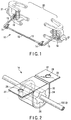
- FIG. 1 shows a suspension 20 for front wheels of a vehicle provided with a stabilizer 10.
- the suspension 20 (indicated by two-dot chain lines) is a double-wishbone suspension.
- the front wheels and the like (not shown) are mounted on left- and right-hand axle portions 21.
- the stabilizer 10 is composed of a stabilizer bar 12, fixing members 14 that fix the stabilizer bar 12 to a vehicle body (not shown), stabilizer links 16 that connect end portions of the stabilizer bar 12 individually to operating parts of the suspension 20, etc.
- the stabilizer bar 12 is composed of a torsion part 13 spanning the width of the vehicle body and arm portions 15 individually formed on the opposite ends of the torsion part 13 and which is substantially U-shaped.
- the arm portions 15 of the stabilizer bar 12 follow such actions, whereupon the torsion part 13 is twisted so that the suspension 20 is kept stable by its torsional reaction force.
- each fixing member 14 is composed of a mounting fixture 22, a rubber bush 24, and a sheathing 26, and is fixed to a frame part (not shown) of the vehicle body.
- the mounting fixture 22 is a substantially U-shaped metal plate, and lugs 27 extend individually sideways from the opposite ends of the fixture 22.
- a bolt hole 28 is formed in each lug 27.
- a bolt (not shown) is passed through each bolt hole 28, whereby the mounting fixture 22 is fixed to the frame of the vehicle body.
- the rubber bush 24 is formed of a rubber material with a predetermined hardness and has a shape suitable for the U-shape inside the mounting fixture 22. Further, the rubber bush 24 is formed with a through-hole 30 that penetrates the substantial center of the rubber bush 24. The through-hole 30 has an inner surface shape corresponding to the external shape of the sheathing 26. Furthermore, the rubber bush 24 is formed with a cut portion 32 that extends from inside the through-hole 30 to the outer surface of the rubber bush 24. The cut portion 32 in the rubber bush 24 enables the through-hole 30 to open above and below the cut portion 32.
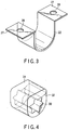
- the sheathing 26 is made of a resin and composed of a collar portion 34 and a cylinder portion 36 continuous with the collar portion 34, as shown in FIG. 5 .
- the sheathing 26 is formed by, for example, injection molding and is integrally fixed to the stabilizer bar 12.
- the collar portion 34 is a discoid that is formed substantially at right angles to the stabilizer bar 12, as shown in FIG. 6 .
- the cylinder portion 36 is formed substantially parallel to the axis of the stabilizer bar 12 and has a rugged configuration on its outer peripheral surface.
- the rugged configuration is a point-symmetric shape such that its cross section perpendicular to the central axis of the stabilizer bar 12 has six uniform tops.
- FIG. 6 is a sectional view of the fixing member 14 taken along a line that passes through the tops and bottoms of the rugged configuration of cylinder portion 36.
- the sheathing 26 basically has a sufficient hardness such that it cannot be easily deformed and is fixed in close proximity to the stabilizer bar 12 without a gap.
- the sheathing 26 is molded after the outer surface of the stabilizer bar 12 is shot-peened and before the outer surface of the stabilizer bar 12 is coated. Fine irregularities are formed on the surface of the stabilizer bar 12 by shot peening, so that the bite of the sheathing 26 on the stabilizer bar 12 is improved by the anchor effect of the irregularities.
- the shot peening may be that conventionally performed to improve the durability and the like of the stabilizer bar 12. Further, any other processing means may be used for the purpose as long as the bite of the resin on the stabilizer bar 12 can be improved.
- the sheathing 26 may be molded on the stabilizer bar 12 with a smooth surface provided that the resin of the sheathing 26 and the stabilizer bar 12 to be combined are fully fixed. If the adhesion of the resin to the stabilizer bar 12 is unsatisfactory, in contrast with this, a molded portion of the sheathing 26 may additionally be knurled or serrated after being shot-peened.
- the rubber bush 24 has an external shape larger than the internal shape of the mounting fixture 22, and the through-hole 30 is formed with a shape smaller than the external shape of the cylinder portion 36 of the sheathing 26.
- the mounting fixture 22 is fitted on the outside of the rubber bush 24, which is mounted on the sheathing 26, and fixed to the vehicle body frame, the rubber bush 24 is pressed inward by both the sheathing 26 and the mounting fixture 22.
- the fixing member 14 that is fixed to the vehicle body frame is kept in a state such that a compressive force (preload) is continually applied to the inside of the rubber bush 24.
- the preload should be set to a sufficiently large value such that it cannot be reduced to zero when the stabilizer 10 operates.
- the through-hole 30 may be formed with a shape equal to or larger than the external shape of the sheathing 26. Also in this case, the through-hole 30 is formed so that the sheathing 26 is pressed inward and subjected to a compressive force by the rubber bush 24 when the rubber bush 24 is attached to the mounting fixture 22.
- the sheathing 26 is formed on the surface of the stabilizer bar 12 by injection molding, the stabilizer bar 12 and the sheathing 26 closely contact each other, thereby preventing water or dust from infiltrating or adhering between them. Accordingly, the surface of the stabilizer bar 12 between the stabilizer bar 12 and the sheathing 26 can be prevented from rusting, so that its durability can be improved. Since the sheathing 26 and the stabilizer bar 12 cannot be dislocated from each other, moreover, no noise can be produced.
- the sheathing 26 is formed on the stabilizer bar 12 by injection molding, it can be provided with ease. Further, the sheathing 26 can be securely fixed to the stabilizer bar 12 by the shot peening for the stabilizer bar 12 before molding without requiring any special processing before the injection molding. Thus, the time required for labor and processing can be shortened, so that the manufacturing cost can be reduced considerably, as compared with the case where a conventional rubber bush is adhesively bonded or vulcanization-molded.
- the rubber bush 24 can be opened at its cut portion 32 and assembled to the sheathing 26, so that the stabilizer bar 12 can be easily attached to the vehicle body frame. Since the rubber bush 24 and the sheathing 26 are not adhesively bonded, moreover, the rubber bush 24 can be easily removed from the sheathing 26. Thus, the rubber bush 24 can be replaced by a simple operation, so that the replacement cost can be reduced.
- the stabilizer effect can be fully exhibited.
- a wheel on one side drops into a depression so that one side of the suspension 20 lowers while the vehicle is running.
- an angle is formed or extended between the left- and right-hand arm portions 15, which twists the torsion part 13 and produces a reaction force.
- the sheathings 26 are also rotated around their respective axes, so that the cylinder portions 36 rotate, thereby compressing the rubber material of the rubber bushes 24 between the tops of the cylinder portions 36 in the rotating direction of the stabilizer bar 12.
- the compressive reaction force of the rubber bushes 24 is transmitted to the arm portions 15, whereby the responsiveness at the initial stage of rolling is improved, so that the driving stability of the vehicle is enhanced.
- the stabilizer 10 can be reduced in weight and cost.
- the sheathing 26 may be fixed to the stabilizer bar 12 by adhesive bonding or welding instead of injection molding.
- the sheathing 26 should preferably be formed of a resin, moreover, it may alternatively be formed of another material, e.g., hard rubber, synthetic rubber, etc.
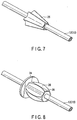
- FIG. 7 shows a sheathing 26.
- the sheathing 26 has an axially rugged configuration on its outer peripheral surface. It is formed so as not to be circumferentially dislocated from a rubber bush 24 and is axially tapered on one side. Further, a rugged configuration for integral assembly is formed on the inner surface of a through-hole 30 of the rubber bush 24 so as to correspond to the rugged configuration of the sheathing 26.
- FIG. 8 shows a second embodiment of the invention.
- each top part of a cylinder portion 36 has a convex shape in cross-section when cut along a plane that passes through the central axis of a stabilizer bar 12. If a sheathing 26 formed in this manner is assembled to a rubber bush 24 that has a through-hole 30 corresponding to this rugged configuration, circumferential dislocation can be restrained by the top parts. Since the top parts are convex with respect to the axial direction, moreover, an axial movement can also be restrained.
- each top part of the cylinder portion 36 may have a concave shape, depressed in the center, instead of being convex.
- FIG. 9 shows an example in which the transverse width of a rubber bush 24 is longer than that of a sheathing 26 along the axis of a stabilizer bar 12.
- the sheathing 26 covers the inside of the rubber bush 24 so that water, dust, etc., can be prevented from infiltrating between the rubber bush 24 and the sheathing 26.
- the sheathing 26 may be formed so that its axial width is longer than that of the rubber bush 24 along the stabilizer bar 12, that is, the sheathing 26 is exposed on the opposite sides of the rubber bush 24.
- the sheathing 26 is formed axially with the stabilizer bar 12 in the example described above, they need not always be coaxial with each other. Further, the cross section of the stabilizer bar 12 may be of any desired shape other than a circular shape and may be either hollow or solid. Although the fixing member 14 is provided on the frame of the vehicle body, the distal end of the arm portion may be attached to the frame.
- the sheathing 26 should only be formed with one irregularity provided that the rubber bush 24 and the sheathing 26 can engage each other at least circumferentially.
- the collar portion 34 may be formed in any desired position along the axis, e.g., in the center of the sheathing 26, instead of being formed on the axial end portion of the sheathing 26.
- the outer surface of the sheathing 26 and the inner surface of the rubber bush 24 need not be in close contact with each other throughout the circumference of the sheathing 26. Further, the sheathing 26 and the rubber bush 24 may be configured so that a gap is formed between them when the stabilizer 10 is driven to twist the stabilizer bar 12.
- the sheathing 26 may be provided with a projection member that is configured to be inserted through the inner surface of the rubber bush 24.
- the projection member may be inserted into a crack that is formed in the inner wall surface of the through-hole 30 of the rubber bush 24 by the projection member.
- a plurality of projections may be formed on the surface of the sheathing 26 and caused to engage with the inner surface of the through-hole 30 of the rubber bush 24.
- the rubber bush 24 may be attached to the sheathing 26 through the axial end of the stabilizer bar 12 without being formed with the cut portion 32.
- the mounting fixture 22 may be fitted into a hollow that is formed in the outer peripheral surface of the rubber bush 24. If this is done, the rubber bush 24 can be prevented from being disengaged from the mounting fixture 22 even when the rubber bush 24 is subjected to a force along the axis of the stabilizer bar 12.
- the present invention is applicable to a vehicle stabilizer.
Landscapes
- Engineering & Computer Science (AREA)
- General Engineering & Computer Science (AREA)
- Mechanical Engineering (AREA)
- Vehicle Body Suspensions (AREA)
- Springs (AREA)
Applications Claiming Priority (2)
| Application Number | Priority Date | Filing Date | Title |
|---|---|---|---|
| JP2008040500A JP2009196505A (ja) | 2008-02-21 | 2008-02-21 | 車両用スタビライザ |
| PCT/JP2009/053616 WO2009104815A1 (en) | 2008-02-21 | 2009-02-20 | Vehicle stabilizer |
Publications (3)
| Publication Number | Publication Date |
|---|---|
| EP2244896A1 EP2244896A1 (en) | 2010-11-03 |
| EP2244896A4 EP2244896A4 (en) | 2012-01-04 |
| EP2244896B1 true EP2244896B1 (en) | 2016-04-13 |
Family
ID=40985680
Family Applications (1)
| Application Number | Title | Priority Date | Filing Date |
|---|---|---|---|
| EP09711942.4A Not-in-force EP2244896B1 (en) | 2008-02-21 | 2009-02-20 | Vehicle stabilizer |
Country Status (7)
| Country | Link |
|---|---|
| US (2) | US20100244395A1 (ja) |
| EP (1) | EP2244896B1 (ja) |
| JP (1) | JP2009196505A (ja) |
| KR (1) | KR20100093604A (ja) |
| CN (1) | CN101909911B (ja) |
| ES (1) | ES2576030T3 (ja) |
| WO (1) | WO2009104815A1 (ja) |
Families Citing this family (14)
| Publication number | Priority date | Publication date | Assignee | Title |
|---|---|---|---|---|
| US20080277847A1 (en) * | 2007-05-11 | 2008-11-13 | The Pullman Company | Bushing having self-lubricating overmold |
| JP4663752B2 (ja) * | 2008-04-14 | 2011-04-06 | 日本発條株式会社 | スタビライザ装置およびその製造方法 |
| JP5748318B2 (ja) | 2008-07-18 | 2015-07-15 | 日本発條株式会社 | スタビライザー装置 |
| DE102010033036A1 (de) * | 2010-08-02 | 2012-02-02 | Benteler Automobiltechnik Gmbh | Verfahren zur Herstellung eines Stabilisators mit Stabilisatorlager |
| JP5478472B2 (ja) * | 2010-12-07 | 2014-04-23 | 日本発條株式会社 | ブッシュ・ブラケット一体スタビライザーバー |
| JP5860273B2 (ja) * | 2011-11-25 | 2016-02-16 | オイレス工業株式会社 | スタビライザブッシュおよび軸受装置 |
| JP5988488B2 (ja) * | 2012-10-26 | 2016-09-07 | 日本発條株式会社 | スタビライザ用ブシュ、接着用治具、および、接着方法 |
| US9004511B1 (en) | 2013-10-09 | 2015-04-14 | Honda Motor Co., Ltd. | Stabilizing bar mounting structure |
| DE102015104864A1 (de) * | 2015-03-30 | 2016-10-06 | Thyssenkrupp Ag | Lagerelement für einen Stabilisator eines Fahrzeugs |
| JP6347226B2 (ja) | 2015-04-16 | 2018-06-27 | トヨタ自動車株式会社 | スタビライザバー取付装置、スタビライザバー取付用ブラケット |
| EP3495177B1 (en) * | 2016-08-03 | 2021-09-01 | NHK Spring Co., Ltd. | Vehicle spring production method and vehicle spring |
| DE102017215171A1 (de) | 2017-08-30 | 2019-02-28 | Ford Global Technologies, Llc | Verfahren zur Herstellung eines Fahrzeuglenkers für eine Radaufhängung sowie Fahrzeuglenker |
| JP6489180B2 (ja) * | 2017-09-04 | 2019-03-27 | マツダ株式会社 | 車両用サスペンション装置 |
| DE102019132875A1 (de) | 2018-12-26 | 2020-07-02 | Hyundai Motor Company | Verbundmaterialbuchse |
Family Cites Families (29)
| Publication number | Priority date | Publication date | Assignee | Title |
|---|---|---|---|---|
| GB8929056D0 (en) | 1989-12-22 | 1990-02-28 | Tempered Spring Company The Li | Anti-roll bars |
| JPH0442937U (ja) * | 1990-08-09 | 1992-04-13 | ||
| US5413374A (en) * | 1991-08-30 | 1995-05-09 | Nai Neway, Inc. | Adjustable bushing |
| US5224790A (en) | 1992-01-07 | 1993-07-06 | Gencorp Inc. | Stabilizer bar slip bushing with axial restraint |
| GB9200905D0 (en) * | 1992-01-16 | 1992-03-11 | Tempered Spring Company The Li | Method of moulding a non-metallic component onto a metal bar |
| CA2108983A1 (en) * | 1992-11-10 | 1994-05-11 | Robert L. Carper | Bushing for an automobile suspension system |
| US5588209A (en) * | 1994-05-04 | 1996-12-31 | The Tempered Spring Company Limited | Method and apparatus to manufacture stabilizer bars |
| IT1285856B1 (it) * | 1996-05-03 | 1998-06-24 | Rejna Spa | Dispositivo di posizionamento per barre stabilizzatrici, barra stabilizzatrice e sistema di stabilizzazione per veicoli utilizzanti |
| DE19738769A1 (de) * | 1997-09-04 | 1999-03-11 | Bayerische Motoren Werke Ag | Lagerung eines Stabilisators an einem Kraftfahrzeug |
| DE19912268A1 (de) * | 1999-03-19 | 2000-09-28 | Audi Ag | Lagerung für einen Stabilisator |
| US6474631B2 (en) * | 2000-03-16 | 2002-11-05 | Toyo Tire & Rubber Co., Ltd. | Stabilizer bushing |
| JP2001270315A (ja) * | 2000-03-24 | 2001-10-02 | Tokai Rubber Ind Ltd | ゴムブッシュ付きスタビライザーバー |
| JP2002331326A (ja) * | 2001-03-08 | 2002-11-19 | Nhk Spring Co Ltd | 中空スタビライザおよびその製造方法 |
| JP3934957B2 (ja) * | 2002-02-21 | 2007-06-20 | 日本発条株式会社 | 車両用スタビライザおよびその組付方法 |
| EP1344662B1 (de) * | 2002-03-13 | 2006-05-03 | Ford Global Technologies, LLC | Stabilisatorlager für ein Kraftfahrzeug |
| EP1378382B1 (de) * | 2002-07-02 | 2006-03-01 | Ford Global Technologies, LLC | Radaufhängung für ein Kraftfahrzeug mit einer Querblattfeder |
| US7010950B2 (en) * | 2003-01-17 | 2006-03-14 | Visteon Global Technologies, Inc. | Suspension component having localized material strengthening |
| JP4301868B2 (ja) * | 2003-06-05 | 2009-07-22 | マツダ株式会社 | 自動車のドア構造 |
| KR20050092894A (ko) | 2004-03-17 | 2005-09-23 | 현대모비스 주식회사 | 스테빌라이저 바 마운팅 장치 |
| US20050214560A1 (en) * | 2004-03-25 | 2005-09-29 | Stephen Yue | Thermal spray reinforcement of a stabilizer bar |
| JP2006027311A (ja) | 2004-07-12 | 2006-02-02 | Toyo Tire & Rubber Co Ltd | ゴムブッシュ付きスタビライザーバー |
| GB2417054B (en) * | 2004-08-12 | 2006-06-28 | Minebea Co Ltd | A resilient bush |
| US7318593B2 (en) * | 2004-10-15 | 2008-01-15 | Ford Global Technologies, Llc | Stabilizer bar and bushing assembly |
| KR100658294B1 (ko) | 2005-05-27 | 2006-12-14 | 대원강업주식회사 | 발란스 암의 횡방향 밀림방지장치 |
| US7448636B2 (en) * | 2005-10-14 | 2008-11-11 | American Axle & Manufacturing, Inc. | Stabilizer bar |
| US20070241526A1 (en) * | 2006-04-13 | 2007-10-18 | Martin Joseph Plante | Vehicle stabilizer bar bushing assembly |
| SE529261C2 (sv) * | 2006-04-28 | 2007-06-12 | Volvo Lastvagnar Ab | Krängningshämmarstag för ett fordon |
| US20070257462A1 (en) * | 2006-05-02 | 2007-11-08 | Meritor Suspension Systems Company, Us | Die cast stabilizer bar ends |
| JP5748318B2 (ja) | 2008-07-18 | 2015-07-15 | 日本発條株式会社 | スタビライザー装置 |
-
2008
- 2008-02-21 JP JP2008040500A patent/JP2009196505A/ja active Pending
-
2009
- 2009-02-20 ES ES09711942.4T patent/ES2576030T3/es active Active
- 2009-02-20 EP EP09711942.4A patent/EP2244896B1/en not_active Not-in-force
- 2009-02-20 CN CN2009801024975A patent/CN101909911B/zh not_active Expired - Fee Related
- 2009-02-20 WO PCT/JP2009/053616 patent/WO2009104815A1/en active Application Filing
- 2009-02-20 KR KR1020107015746A patent/KR20100093604A/ko active Search and Examination
-
2010
- 2010-06-10 US US12/797,807 patent/US20100244395A1/en not_active Abandoned
-
2012
- 2012-05-14 US US13/471,201 patent/US8382129B2/en active Active
Also Published As
| Publication number | Publication date |
|---|---|
| US20100244395A1 (en) | 2010-09-30 |
| JP2009196505A (ja) | 2009-09-03 |
| CN101909911B (zh) | 2012-10-03 |
| WO2009104815A1 (en) | 2009-08-27 |
| ES2576030T3 (es) | 2016-07-05 |
| EP2244896A4 (en) | 2012-01-04 |
| EP2244896A1 (en) | 2010-11-03 |
| KR20100093604A (ko) | 2010-08-25 |
| US20120223499A1 (en) | 2012-09-06 |
| US8382129B2 (en) | 2013-02-26 |
| CN101909911A (zh) | 2010-12-08 |
Similar Documents
| Publication | Publication Date | Title |
|---|---|---|
| EP2244896B1 (en) | Vehicle stabilizer | |
| KR101538422B1 (ko) | 비틀림 슬립을 갖는 굴곡된 부싱 | |
| US6363613B1 (en) | Torsion bar shoulder bearing | |
| KR101312710B1 (ko) | 차량용 샤시 부품 연결용 단일축 댐핑 조인트 | |
| US6889988B2 (en) | Variable rate gripped bushing system | |
| US7500685B2 (en) | Bushing support ring for stabilizer bar | |
| US6845994B2 (en) | Gripped bushing system with alternating radial stiffness | |
| CN108688423B (zh) | 车辆悬架衬套组件及其组装方法 | |
| US6845995B2 (en) | Method of forming compression gripped bushing system | |
| KR20130058724A (ko) | 너클 및 부싱 조립체 | |
| EP1395451B1 (en) | Link assembly for a vehicle suspension system | |
| CN1222117A (zh) | 包括一种横梁和后臂的挠性轴 | |
| KR20200020710A (ko) | 차량 섀시용 스태빌라이저 바 및 이러한 스태빌라이저 바를 제조하기 위한 방법 | |
| US20090020976A1 (en) | Bushing having high axial spring rate and method of manufacturing | |
| US20200047578A1 (en) | Dual compound elastomer bushing for vehicle suspension component | |
| KR100658294B1 (ko) | 발란스 암의 횡방향 밀림방지장치 | |
| CN107848353B (zh) | 用于纵臂式车辆悬架的连接组件 | |
| JP4614255B2 (ja) | スタビライザブッシュの成形方法 | |
| JP3466974B2 (ja) | サスペンション連結部材 | |
| KR102463446B1 (ko) | 스테빌라이저 부시 | |
| KR20180068573A (ko) | 서스펜션용 인슐레이터 | |
| JP4045770B2 (ja) | サスペンションクロスメンバー取付用ブッシュ、及びサスペンションクロスメンバーの取付構造 | |
| EP3670940B1 (en) | Hybrid suspension arm including a ball joint | |
| US20240151288A1 (en) | Elastomeric bushing with ferrule | |
| JP3474485B2 (ja) | 防振ブッシュ及びその製造方法 |
Legal Events
| Date | Code | Title | Description |
|---|---|---|---|
| PUAI | Public reference made under article 153(3) epc to a published international application that has entered the european phase |
Free format text: ORIGINAL CODE: 0009012 |
|
| 17P | Request for examination filed |
Effective date: 20100611 |
|
| AK | Designated contracting states |
Kind code of ref document: A1 Designated state(s): AT BE BG CH CY CZ DE DK EE ES FI FR GB GR HR HU IE IS IT LI LT LU LV MC MK MT NL NO PL PT RO SE SI SK TR |
|
| AX | Request for extension of the european patent |
Extension state: AL BA RS |
|
| DAX | Request for extension of the european patent (deleted) | ||
| A4 | Supplementary search report drawn up and despatched |
Effective date: 20111205 |
|
| RIC1 | Information provided on ipc code assigned before grant |
Ipc: F16F 1/36 20060101ALI20111129BHEP Ipc: F16F 1/14 20060101ALI20111129BHEP Ipc: F16F 1/16 20060101ALI20111129BHEP Ipc: B60G 21/055 20060101AFI20111129BHEP |
|
| 17Q | First examination report despatched |
Effective date: 20130104 |
|
| GRAP | Despatch of communication of intention to grant a patent |
Free format text: ORIGINAL CODE: EPIDOSNIGR1 |
|
| INTG | Intention to grant announced |
Effective date: 20151006 |
|
| GRAS | Grant fee paid |
Free format text: ORIGINAL CODE: EPIDOSNIGR3 |
|
| GRAA | (expected) grant |
Free format text: ORIGINAL CODE: 0009210 |
|
| AK | Designated contracting states |
Kind code of ref document: B1 Designated state(s): AT BE BG CH CY CZ DE DK EE ES FI FR GB GR HR HU IE IS IT LI LT LU LV MC MK MT NL NO PL PT RO SE SI SK TR |
|
| REG | Reference to a national code |
Ref country code: GB Ref legal event code: FG4D |
|
| REG | Reference to a national code |
Ref country code: AT Ref legal event code: REF Ref document number: 789705 Country of ref document: AT Kind code of ref document: T Effective date: 20160415 Ref country code: CH Ref legal event code: EP |
|
| REG | Reference to a national code |
Ref country code: IE Ref legal event code: FG4D |
|
| REG | Reference to a national code |
Ref country code: DE Ref legal event code: R096 Ref document number: 602009037735 Country of ref document: DE |
|
| REG | Reference to a national code |
Ref country code: ES Ref legal event code: FG2A Ref document number: 2576030 Country of ref document: ES Kind code of ref document: T3 Effective date: 20160705 |
|
| REG | Reference to a national code |
Ref country code: LT Ref legal event code: MG4D |
|
| REG | Reference to a national code |
Ref country code: AT Ref legal event code: MK05 Ref document number: 789705 Country of ref document: AT Kind code of ref document: T Effective date: 20160413 |
|
| REG | Reference to a national code |
Ref country code: NL Ref legal event code: MP Effective date: 20160413 |
|
| PG25 | Lapsed in a contracting state [announced via postgrant information from national office to epo] |
Ref country code: FI Free format text: LAPSE BECAUSE OF FAILURE TO SUBMIT A TRANSLATION OF THE DESCRIPTION OR TO PAY THE FEE WITHIN THE PRESCRIBED TIME-LIMIT Effective date: 20160413 Ref country code: NO Free format text: LAPSE BECAUSE OF FAILURE TO SUBMIT A TRANSLATION OF THE DESCRIPTION OR TO PAY THE FEE WITHIN THE PRESCRIBED TIME-LIMIT Effective date: 20160713 Ref country code: NL Free format text: LAPSE BECAUSE OF FAILURE TO SUBMIT A TRANSLATION OF THE DESCRIPTION OR TO PAY THE FEE WITHIN THE PRESCRIBED TIME-LIMIT Effective date: 20160413 Ref country code: PL Free format text: LAPSE BECAUSE OF FAILURE TO SUBMIT A TRANSLATION OF THE DESCRIPTION OR TO PAY THE FEE WITHIN THE PRESCRIBED TIME-LIMIT Effective date: 20160413 Ref country code: LT Free format text: LAPSE BECAUSE OF FAILURE TO SUBMIT A TRANSLATION OF THE DESCRIPTION OR TO PAY THE FEE WITHIN THE PRESCRIBED TIME-LIMIT Effective date: 20160413 |
|
| PG25 | Lapsed in a contracting state [announced via postgrant information from national office to epo] |
Ref country code: AT Free format text: LAPSE BECAUSE OF FAILURE TO SUBMIT A TRANSLATION OF THE DESCRIPTION OR TO PAY THE FEE WITHIN THE PRESCRIBED TIME-LIMIT Effective date: 20160413 Ref country code: PT Free format text: LAPSE BECAUSE OF FAILURE TO SUBMIT A TRANSLATION OF THE DESCRIPTION OR TO PAY THE FEE WITHIN THE PRESCRIBED TIME-LIMIT Effective date: 20160816 Ref country code: LV Free format text: LAPSE BECAUSE OF FAILURE TO SUBMIT A TRANSLATION OF THE DESCRIPTION OR TO PAY THE FEE WITHIN THE PRESCRIBED TIME-LIMIT Effective date: 20160413 Ref country code: HR Free format text: LAPSE BECAUSE OF FAILURE TO SUBMIT A TRANSLATION OF THE DESCRIPTION OR TO PAY THE FEE WITHIN THE PRESCRIBED TIME-LIMIT Effective date: 20160413 Ref country code: SE Free format text: LAPSE BECAUSE OF FAILURE TO SUBMIT A TRANSLATION OF THE DESCRIPTION OR TO PAY THE FEE WITHIN THE PRESCRIBED TIME-LIMIT Effective date: 20160413 Ref country code: GR Free format text: LAPSE BECAUSE OF FAILURE TO SUBMIT A TRANSLATION OF THE DESCRIPTION OR TO PAY THE FEE WITHIN THE PRESCRIBED TIME-LIMIT Effective date: 20160714 |
|
| PG25 | Lapsed in a contracting state [announced via postgrant information from national office to epo] |
Ref country code: IT Free format text: LAPSE BECAUSE OF FAILURE TO SUBMIT A TRANSLATION OF THE DESCRIPTION OR TO PAY THE FEE WITHIN THE PRESCRIBED TIME-LIMIT Effective date: 20160413 Ref country code: BE Free format text: LAPSE BECAUSE OF FAILURE TO SUBMIT A TRANSLATION OF THE DESCRIPTION OR TO PAY THE FEE WITHIN THE PRESCRIBED TIME-LIMIT Effective date: 20160413 |
|
| REG | Reference to a national code |
Ref country code: FR Ref legal event code: PLFP Year of fee payment: 9 |
|
| REG | Reference to a national code |
Ref country code: DE Ref legal event code: R097 Ref document number: 602009037735 Country of ref document: DE |
|
| PG25 | Lapsed in a contracting state [announced via postgrant information from national office to epo] |
Ref country code: DK Free format text: LAPSE BECAUSE OF FAILURE TO SUBMIT A TRANSLATION OF THE DESCRIPTION OR TO PAY THE FEE WITHIN THE PRESCRIBED TIME-LIMIT Effective date: 20160413 Ref country code: CZ Free format text: LAPSE BECAUSE OF FAILURE TO SUBMIT A TRANSLATION OF THE DESCRIPTION OR TO PAY THE FEE WITHIN THE PRESCRIBED TIME-LIMIT Effective date: 20160413 Ref country code: EE Free format text: LAPSE BECAUSE OF FAILURE TO SUBMIT A TRANSLATION OF THE DESCRIPTION OR TO PAY THE FEE WITHIN THE PRESCRIBED TIME-LIMIT Effective date: 20160413 Ref country code: SK Free format text: LAPSE BECAUSE OF FAILURE TO SUBMIT A TRANSLATION OF THE DESCRIPTION OR TO PAY THE FEE WITHIN THE PRESCRIBED TIME-LIMIT Effective date: 20160413 Ref country code: RO Free format text: LAPSE BECAUSE OF FAILURE TO SUBMIT A TRANSLATION OF THE DESCRIPTION OR TO PAY THE FEE WITHIN THE PRESCRIBED TIME-LIMIT Effective date: 20160413 |
|
| PLBE | No opposition filed within time limit |
Free format text: ORIGINAL CODE: 0009261 |
|
| STAA | Information on the status of an ep patent application or granted ep patent |
Free format text: STATUS: NO OPPOSITION FILED WITHIN TIME LIMIT |
|
| 26N | No opposition filed |
Effective date: 20170116 |
|
| PG25 | Lapsed in a contracting state [announced via postgrant information from national office to epo] |
Ref country code: SI Free format text: LAPSE BECAUSE OF FAILURE TO SUBMIT A TRANSLATION OF THE DESCRIPTION OR TO PAY THE FEE WITHIN THE PRESCRIBED TIME-LIMIT Effective date: 20160413 |
|
| REG | Reference to a national code |
Ref country code: DE Ref legal event code: R082 Ref document number: 602009037735 Country of ref document: DE Representative=s name: MEISSNER BOLTE PATENTANWAELTE RECHTSANWAELTE P, DE Ref country code: DE Ref legal event code: R081 Ref document number: 602009037735 Country of ref document: DE Owner name: NHK SPRING CO., LTD., YOKOHAMA-SHI, JP Free format text: FORMER OWNERS: NHK INTERNATIONAL CORP., WIXOM, MICH., US; NHK SPRING CO., LTD., YOKOHAMA-SHI, KANAGAWA, JP |
|
| PG25 | Lapsed in a contracting state [announced via postgrant information from national office to epo] |
Ref country code: MC Free format text: LAPSE BECAUSE OF FAILURE TO SUBMIT A TRANSLATION OF THE DESCRIPTION OR TO PAY THE FEE WITHIN THE PRESCRIBED TIME-LIMIT Effective date: 20160413 |
|
| REG | Reference to a national code |
Ref country code: CH Ref legal event code: PL |
|
| GBPC | Gb: european patent ceased through non-payment of renewal fee |
Effective date: 20170220 |
|
| PG25 | Lapsed in a contracting state [announced via postgrant information from national office to epo] |
Ref country code: LI Free format text: LAPSE BECAUSE OF NON-PAYMENT OF DUE FEES Effective date: 20170228 Ref country code: CH Free format text: LAPSE BECAUSE OF NON-PAYMENT OF DUE FEES Effective date: 20170228 |
|
| REG | Reference to a national code |
Ref country code: ES Ref legal event code: PC2A Owner name: NHK SPRING CO., LTD. Effective date: 20171117 |
|
| REG | Reference to a national code |
Ref country code: IE Ref legal event code: MM4A |
|
| PG25 | Lapsed in a contracting state [announced via postgrant information from national office to epo] |
Ref country code: LU Free format text: LAPSE BECAUSE OF NON-PAYMENT OF DUE FEES Effective date: 20170220 |
|
| REG | Reference to a national code |
Ref country code: FR Ref legal event code: PLFP Year of fee payment: 10 |
|
| PG25 | Lapsed in a contracting state [announced via postgrant information from national office to epo] |
Ref country code: GB Free format text: LAPSE BECAUSE OF NON-PAYMENT OF DUE FEES Effective date: 20170220 Ref country code: IE Free format text: LAPSE BECAUSE OF NON-PAYMENT OF DUE FEES Effective date: 20170220 |
|
| REG | Reference to a national code |
Ref country code: FR Ref legal event code: TP Owner name: NHK SPRING CO., LTD., JP Effective date: 20180205 |
|
| PG25 | Lapsed in a contracting state [announced via postgrant information from national office to epo] |
Ref country code: MT Free format text: LAPSE BECAUSE OF NON-PAYMENT OF DUE FEES Effective date: 20170220 |
|
| PG25 | Lapsed in a contracting state [announced via postgrant information from national office to epo] |
Ref country code: HU Free format text: LAPSE BECAUSE OF FAILURE TO SUBMIT A TRANSLATION OF THE DESCRIPTION OR TO PAY THE FEE WITHIN THE PRESCRIBED TIME-LIMIT; INVALID AB INITIO Effective date: 20090220 |
|
| PG25 | Lapsed in a contracting state [announced via postgrant information from national office to epo] |
Ref country code: BG Free format text: LAPSE BECAUSE OF FAILURE TO SUBMIT A TRANSLATION OF THE DESCRIPTION OR TO PAY THE FEE WITHIN THE PRESCRIBED TIME-LIMIT Effective date: 20160413 |
|
| PG25 | Lapsed in a contracting state [announced via postgrant information from national office to epo] |
Ref country code: CY Free format text: LAPSE BECAUSE OF NON-PAYMENT OF DUE FEES Effective date: 20160413 |
|
| PG25 | Lapsed in a contracting state [announced via postgrant information from national office to epo] |
Ref country code: MK Free format text: LAPSE BECAUSE OF FAILURE TO SUBMIT A TRANSLATION OF THE DESCRIPTION OR TO PAY THE FEE WITHIN THE PRESCRIBED TIME-LIMIT Effective date: 20160413 |
|
| PG25 | Lapsed in a contracting state [announced via postgrant information from national office to epo] |
Ref country code: TR Free format text: LAPSE BECAUSE OF FAILURE TO SUBMIT A TRANSLATION OF THE DESCRIPTION OR TO PAY THE FEE WITHIN THE PRESCRIBED TIME-LIMIT Effective date: 20160413 |
|
| PGFP | Annual fee paid to national office [announced via postgrant information from national office to epo] |
Ref country code: ES Payment date: 20200302 Year of fee payment: 12 Ref country code: DE Payment date: 20200204 Year of fee payment: 12 |
|
| PGFP | Annual fee paid to national office [announced via postgrant information from national office to epo] |
Ref country code: FR Payment date: 20200113 Year of fee payment: 12 |
|
| PG25 | Lapsed in a contracting state [announced via postgrant information from national office to epo] |
Ref country code: IS Free format text: LAPSE BECAUSE OF FAILURE TO SUBMIT A TRANSLATION OF THE DESCRIPTION OR TO PAY THE FEE WITHIN THE PRESCRIBED TIME-LIMIT Effective date: 20160813 |
|
| REG | Reference to a national code |
Ref country code: DE Ref legal event code: R119 Ref document number: 602009037735 Country of ref document: DE |
|
| PG25 | Lapsed in a contracting state [announced via postgrant information from national office to epo] |
Ref country code: DE Free format text: LAPSE BECAUSE OF NON-PAYMENT OF DUE FEES Effective date: 20210901 Ref country code: FR Free format text: LAPSE BECAUSE OF NON-PAYMENT OF DUE FEES Effective date: 20210228 |
|
| REG | Reference to a national code |
Ref country code: ES Ref legal event code: FD2A Effective date: 20220513 |
|
| PG25 | Lapsed in a contracting state [announced via postgrant information from national office to epo] |
Ref country code: ES Free format text: LAPSE BECAUSE OF NON-PAYMENT OF DUE FEES Effective date: 20210221 |