EP2184650A1 - Élément de transport pour transport de poudres, récipient d'accessoire de poudre de développement, et appareil de formation d'images - Google Patents
Élément de transport pour transport de poudres, récipient d'accessoire de poudre de développement, et appareil de formation d'images Download PDFInfo
- Publication number
- EP2184650A1 EP2184650A1 EP09163178A EP09163178A EP2184650A1 EP 2184650 A1 EP2184650 A1 EP 2184650A1 EP 09163178 A EP09163178 A EP 09163178A EP 09163178 A EP09163178 A EP 09163178A EP 2184650 A1 EP2184650 A1 EP 2184650A1
- Authority
- EP
- European Patent Office
- Prior art keywords
- transport
- revolving shaft
- powder
- end part
- support part
- Prior art date
- Legal status (The legal status is an assumption and is not a legal conclusion. Google has not performed a legal analysis and makes no representation as to the accuracy of the status listed.)
- Withdrawn
Links
Images


Classifications
-
- G—PHYSICS
- G03—PHOTOGRAPHY; CINEMATOGRAPHY; ANALOGOUS TECHNIQUES USING WAVES OTHER THAN OPTICAL WAVES; ELECTROGRAPHY; HOLOGRAPHY
- G03G—ELECTROGRAPHY; ELECTROPHOTOGRAPHY; MAGNETOGRAPHY
- G03G15/00—Apparatus for electrographic processes using a charge pattern
- G03G15/06—Apparatus for electrographic processes using a charge pattern for developing
- G03G15/08—Apparatus for electrographic processes using a charge pattern for developing using a solid developer, e.g. powder developer
- G03G15/0822—Arrangements for preparing, mixing, supplying or dispensing developer
- G03G15/0865—Arrangements for supplying new developer
- G03G15/0867—Arrangements for supplying new developer cylindrical developer cartridges, e.g. toner bottles for the developer replenishing opening
- G03G15/087—Developer cartridges having a longitudinal rotational axis, around which at least one part is rotated when mounting or using the cartridge
- G03G15/0872—Developer cartridges having a longitudinal rotational axis, around which at least one part is rotated when mounting or using the cartridge the developer cartridges being generally horizontally mounted parallel to its longitudinal rotational axis
-
- G—PHYSICS
- G03—PHOTOGRAPHY; CINEMATOGRAPHY; ANALOGOUS TECHNIQUES USING WAVES OTHER THAN OPTICAL WAVES; ELECTROGRAPHY; HOLOGRAPHY
- G03G—ELECTROGRAPHY; ELECTROPHOTOGRAPHY; MAGNETOGRAPHY
- G03G15/00—Apparatus for electrographic processes using a charge pattern
-
- G—PHYSICS
- G03—PHOTOGRAPHY; CINEMATOGRAPHY; ANALOGOUS TECHNIQUES USING WAVES OTHER THAN OPTICAL WAVES; ELECTROGRAPHY; HOLOGRAPHY
- G03G—ELECTROGRAPHY; ELECTROPHOTOGRAPHY; MAGNETOGRAPHY
- G03G15/00—Apparatus for electrographic processes using a charge pattern
- G03G15/06—Apparatus for electrographic processes using a charge pattern for developing
- G03G15/08—Apparatus for electrographic processes using a charge pattern for developing using a solid developer, e.g. powder developer
- G03G15/0822—Arrangements for preparing, mixing, supplying or dispensing developer
- G03G15/0877—Arrangements for metering and dispensing developer from a developer cartridge into the development unit
-
- G—PHYSICS
- G03—PHOTOGRAPHY; CINEMATOGRAPHY; ANALOGOUS TECHNIQUES USING WAVES OTHER THAN OPTICAL WAVES; ELECTROGRAPHY; HOLOGRAPHY
- G03G—ELECTROGRAPHY; ELECTROPHOTOGRAPHY; MAGNETOGRAPHY
- G03G2215/00—Apparatus for electrophotographic processes
- G03G2215/08—Details of powder developing device not concerning the development directly
- G03G2215/0802—Arrangements for agitating or circulating developer material
- G03G2215/0816—Agitator type
- G03G2215/0827—Augers
Definitions
- the present invention relates to a transport member for powder transport, a developing powder accommodation container, and an image forming apparatus.
- a developing powder transport apparatus for transporting developing powder is provided in order to supply developing powder consumed in association with image formation or alternatively discard developing powder having remained and having been collected.
- techniques concerning such a developing powder transport apparatus those described in the following JP-A-10-247009 ([0022] to [0024], FIGS. 1 and 3 ), JP-A-2000-305344 ( FIG. 3 ), JP-A-2006-53446 ( FIG. 4 ), and JP-A-2002-268344 ( FIG. 4 ) are known.
- JP-A-10-247009 , JP-A-2000-305344 , JP-A-2006-53446 , and JP-A-2002-268344 describe agitating members and transport members that are formed by bending metal wires such as stainless steel wires into helix shapes in the inside of a cartridge or a developing powder container for accommodating developing powder and that agitate and transport developing powder in the inside when revolved.
- a technical object of the present invention is to improve restorability from deformation caused by a force received at the time of transport of powder such as developing powder.
- the ratio that the transport part occupies in a sectional view taken perpendicular to the revolving shaft at the time of deformation by a force received from developing powder under transport can be increased in comparison with a non-deformed state.
- the second transport part that is located on the upstream side and that receives lower load acting on the transport part and hence suffers smaller deformation is in a double-end supported state. This suppresses a situation that the helix of the transport part is spread so as to contact to the developing powder accommodation part.
- the frontward and rearward directions are defined as the X-axis directions
- the right and left directions are defined as the Y-axis directions
- the up and down directions are defined as the Z-axis directions.
- these directions or sides indicated by arrows X, -X, Y, -Y, Z, and -Z are respectively referred to as frontward, rearward, rightward, leftward, upward, and downward, or front side, rear side, right-hand side, left-hand side, upside, and downside.
- a symbol “ ⁇ ” having a dot “•” in the center represents an arrow directed from the behind of the page to the front side of the page
- a symbol “ ⁇ ” having a cross “ ⁇ ” in the center represents an arrow directed from the front side of the page to the behind of the page.
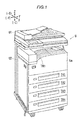
- FIG. 1 is a perspective view showing an image forming apparatus according to exemplary embodiment 1 of the present invention.
- a copying machine U serving as an image forming apparatus has: an auto document feeder U1 arranged in a top end part; and an image forming apparatus body U2 that supports the auto document feeder U1.
- a paper ejection tray TRh is provided that serves as an example of a medium ejection part.
- plural of paper feed trays TR1 to TR4 that serve as examples of medium accommodation containers and that accommodate sheets serving as examples of media are provided in an attachable and detachable manner.
- a front cover Ua is supported that serves as an example of a front open-close member.
- FIG. 2 is an explanation diagram showing the entirety of the image forming apparatus according to exemplary embodiment 1 of the present invention.
- the auto document feeder U1 has: a manuscript feeding unit TG1 for accommodating a stack of plural of manuscripts Gi to be copied; and a manuscript ejection unit TG2 into which each manuscript Gi that is fed from the manuscript feeding unit TG1 and then transported via a transparent manuscript reading position on a manuscript reading surface PG at the upper end of the image forming apparatus body U2 is ejected.
- the image forming apparatus body U2 has: an operation section UI through which a user inputs operation command signals such as an image formation operation start signal; and an exposure optical system A.
- An image information conversion unit IPS converts into image information of black (K), yellow (Y), magenta (M), and cyan (C) the electric signals of RGB inputted from the solid-state image sensor CCD, then stores the information temporarily, and then outputs the stored image information as image information for latent image formation to the latent image forming apparatus drive circuit DL at a predetermined time.
- the image information of black alone is inputted to the latent image forming apparatus drive circuit DL.
- the latent image forming apparatus drive circuit DL has drive circuits (not shown) for individual colors Y, M, C, and K. Then, these drive circuits output signals corresponding to the inputted image information to latent image forming apparatuses LHy, LHm, LHc, and LHk for individual colors at a predetermined time.
- FIG. 3 is an explanation diagram showing a magnified view of the main part of the image forming apparatus according to exemplary embodiment 1.
- Visible image formation apparatuses Uy, Um, Uc, and Uk arranged in the center part in the gravitational direction of the image forming apparatus U serve individually as apparatuses for forming visible images for individual colors Y, M, C, and K.
- Latent image writing light of Y, M, C, and K emitted from individual latent image writing light sources of the latent image forming apparatuses LHy to LHk are respectively incident on the revolving image carriers PRy, PRm, PRc, and PRk.
- the latent image forming apparatuses LHy to LHk are constructed from so-called LED arrays.
- the visible image formation apparatus Uy for Y has a revolving image carrier PRy, an electrostatic charger CRy, a latent image forming apparatus LHy, a developing apparatus Gy, a transfer device T1y, and an image carrier cleaning device CLy.
- the image carrier PRy, the electrostatic charger CRy, and the image carrier cleaning device CLy are constructed in the form of an image carrier unit that can integrally be attached to and detached from the image forming apparatus body U2.
- the visible image formation apparatuses Um, Uc, and Uk are constructed similarly to the visible image formation apparatus Uy for Y
- the image carriers PRy, PRm, PRc, and PRk are electrostatically charged respectively by the electrostatic chargers CRy, CRm, CRc, and CRk. Then, at image writing positions Q1y, Q1m, Q1C, and Q1k, electrostatic latent images are formed in the surfaces with latent image writing light beams Ly, Lm, Lc, and Lk.
- the electrostatic latent images on the surfaces of the image carriers PRy, PRm, PRc, and PRk are developed into toner images serving as examples of visible images, with developing powder held on developing rolls ROy, ROm, ROc, and ROk serving as examples of developing powder holders of the developing apparatuses Gy, Gm, Gc, and Gk.
- the developed toner images are transported to primary transfer regions Q3y, Q3m, Q3c, and Q3k that contact with an intermediate transfer belt B serving as an example of an intermediate transfer body.
- a primary transfer voltage having a polarity opposite to the electrification polarity of the toner is applied onto the primary transfer devices T1y, T1m, T1c, and T1k arranged on the rear face side of the intermediate transfer belt B, at a predetermined time from a power supply circuit E controlled by a control unit C.
- the toner images on the image carriers PRy to PRk are primary-transferred onto the intermediate transfer belt B by the primary transfer devices T1y, T1m, T1c, and T1k.
- Residue and adhering materials on the surfaces of the image carriers PRy, PRm, PRc, and PRk after the primary transfer are cleaned by the image carrier cleaning devices CLy, CLm, CLc, and CLk.
- the cleaned surfaces of the image carriers PRy, PRm, PRc, and PRk are electrostatically re-charged by the electrostatic chargers CRy, CRm, CRc, and CRk.
- a belt module BM is arranged that can be moved vertically and extracted frontward and that serves as an example of an intermediate transfer apparatus.
- the belt module BM has: the intermediate transfer belt B; a belt driving roll Rd serving as an example of an intermediate transfer body driving member; a tension roll Rt serving as an example of an intermediate transfer body extending member; a walking roll Rw serving as an example of a meandering prevention member; an idler roll Rf serving as an example of a follower member; a back-up roll T2a serving as an example of a secondary transfer region opposing member; and the primary transfer devices T1y, T1m, T1c, and T3k.
- the intermediate transfer belt B is supported in a revolvable manner by belt support rolls Rd, Rt, Rw, Rf, and T2a serving as an example of an intermediate transfer body support members constructed from the individual rolls Rd, Rt, Rw, Rf, and T2a.
- a secondary transfer roll T2b is arranged that serves as an example of a secondary transfer member. Then, the rolls T2a and T2b constitute a secondary transfer device T2. Further, a secondary transfer region Q4 is formed in a region where the secondary transfer roll T2b and the intermediate transfer belt B oppose each other.
- the monochrome or multicolor toner image obtained by sequentially transferring and stacking on the intermediate transfer belt B by the primary transfer devices T1y, T1m, T1c, and T1k in the primary transfer regions Q3y, Q3m, Q3c, and Q3k is transported to the secondary transfer region Q4.
- guide rails GR are provided each of which is composed of a pair of left and right guide rails serving as an example of guide members.
- the guide rails GR support the paper feed trays TR1 to TR4 in a manner permitting insertion and extraction in the frontward and rearward directions.
- a sheet S accommodated in the paper feed trays TR1 to TR4 is extracted by a pick up roll Rp serving as an example of a medium extracting member, and then separated individually by a shuffling roll Rs serving as an example of a medium shuffling member.
- the sheet S is transported along a sheet transport path SH serving as an example of a medium transport path by plural of transport rolls Ra that is arranged in the upstream of the secondary transfer region Q4 relative to the sheet transporting direction and that serves as examples of medium transport members, and then sent to a resistance roll Rr serving as an example of a transfer region transport time adjusting member.
- the sheet transport path SH, sheet transporting roll Ra, the resistance roll Rr, and the like constitute a sheet transport apparatus SH+Ra+Rr.
- the resistance roll Rr transports the sheet S to the secondary transfer region Q4.
- the back-up roll T2a is grounded, while a secondary transfer voltage having a polarity opposite to the electrification polarity of the toner is applied onto the secondary transfer device T2 from the power supply circuit E controlled by the control unit C.
- the toner image on the intermediate transfer belt B is transferred onto the sheet S by the secondary transfer device T2.
- the intermediate transfer belt B after the secondary transfer is cleaned by a belt cleaner CLb serving as an example of an intermediate transfer body cleaning device.
- the primary transfer devices T1y to T1k, the intermediate transfer belt B, the secondary transfer device T2, and the like constitute a transfer apparatus T1+B+T2 for transferring the toner images on the surfaces of the image carriers PRy to PRk onto the sheet S.
- the sheet S on which the toner image has been secondary-transferred is transported to a fixing area Q5 serving as a pressuring region formed by a heating roll Fh serving as an example of a fixing member for heating in the fixing apparatus F and a pressuring roll Fp serving as an example of a fixing member for pressurization. Then, heat fixing is performed during the time of passing through the fixing area.
- the sheet S having been processed by heat fixing is ejected from a discharge roll Rh serving as an example of a medium ejection member into the paper ejection tray TRh serving as an example of a medium ejection part.
- mold-releasing agent for improving the releasing of the sheet S from the heating roll is applied onto the surface of the heating roll Fh by a mold-releasing agent coating apparatus Fa.
- toner cartridges Ky, Km, Kc, and Kk are arranged that serve as examples of developing powder accommodation containers for accommodating developing powder of yellow Y, magenta M, cyan C, and black K and that serve as examples of developing powder accommodation containers for transporting and supplying internal developing powder to the image forming apparatus U.
- the developing powder accommodated in the toner cartridges Ky, Km, Kc, and Kk is supplied through developing powder supply paths (not shown) to the developing apparatuses Gy, Gm, Gc, and Gk.
- the developing powder is composed of two-component developing powder containing a magnetic carrier and a toner with external additive.
- the image forming apparatus U has an upper frame UF and a lower frame LF.
- the upper frame UF supports: the visible image formation apparatuses Uy to Uk; and other members such as the belt module BM arranged above the visible image formation apparatuses Uy to Uk.
- the lower frame F supports: the guide rails GR for supporting the paper feed trays TR1 to TR4; and the paper feed members such as the pick up roll Rp, the shuffling roll Rs, and the sheet transporting roll Ra for feeding paper from the trays TR1 to TR3.
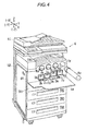
- FIG. 4 is an explanation diagram showing a state that the front cover of the image forming apparatus according to exemplary embodiment 1 is opened and then the toner cartridge for yellow is removed.
- the front cover Ua of the copying machine U is supported on the image forming apparatus body U1 in a revolvable manner by a hinge Ub.
- the front cover Ua is supported in a revolvable manner between a normal position adopted at the time of execution and waiting of image formation operation as shown in FIG. 1 and a maintenance service position adopted when maintenance services such as replacement of the toner cartridges Ky to Kk or the visible image formation apparatuses Uy, Um, Uc, and Uk as shown in FIG. 4 .
- the front cover Ua supports, in its inside, a front panel U4 serving as an example of a front member of the image forming apparatus body U1.
- a front panel U4 serving as an example of a front member of the image forming apparatus body U1.
- cylindrical-hole-shaped toner cartridge attachment parts 1y, 1m, 1c, and 1k are formed which serve as examples of supply container attachment parts and into or from which cylindrical toner cartridges Ky to Kk for individual colors are inserted or removed so that attachment or detachment is achieved.
- process cartridge attachment parts 2y, 2m, 2c, and 2k are formed which serve as examples of attachment parts for visible image formation apparatuses and into or from which the visible image formation apparatuses Uy to Uk are inserted or removed so that attachment or detachment is achieved.
- FIG. 5 is an explanation diagram showing the main part of the toner according to the present exemplary embodiment 1.
- the toner cartridges Ky to Kk for individual colors are constructed similarly to each other.
- the toner cartridge Ky for yellow Y is described in detail.
- detailed description for the other toner cartridges Km, Kc, and Kk is omitted.
- the toner cartridge Ky has a cartridge body 11 that serves as an example of a developing powder accommodation part and that serves as an example of a container body.
- the cartridge body 11 is formed in the shape of an approximate cylinder extending in the frontward and rearward directions, and accommodates, in its inside, developing powder serving as an example of powder.
- the front end part of the cartridge body 11 supports a front cover 12 serving as an example of a container front end member.
- a grip part 12a is formed that is to be gripped by a user when the toner cartridge Ky is to be replaced.
- the rear end part of the cartridge body 11 supports a rear cover 13 serving as an example of a container rear end member.
- a support hole 13a is formed that serves as an example of a to-be-driven transfer member support part.
- a service opening (not shown) is formed that serves as an example of a flow-out part through which developing powder in the cartridge body 11 flows out.
- a shutter 13b is provided that serves as an example of an open-close member moved so as to be opened or closed when the toner cartridge Ky is to be attached to or detached from the image forming apparatus body U1.
- the support hole 13a supports a shaft 14a of a to-be-driven coupling 14 serving as an example of a to-be-driven transfer member, in a revolvable manner in a state of penetrating through.
- the to-be-driven coupling 14 engages with a drive coupling (not shown) that serves as an example of a driving transmission member arranged in the image forming apparatus body U1, so that the driving is transmitted.
- the drive coupling or to-be-driven coupling are described, for example, in JP-A-2004-252184 , JP-A-2005-134452 , and JP-A-2005-181515 , and hence publicly known. Thus, their illustration and detailed description are omitted.
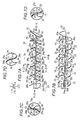
- FIG. 6 is a perspective view showing the transport member according to exemplary embodiment 1.
- FIG. 7A is a side view of an explanation diagram showing the transport member according to exemplary embodiment 1.
- FIG. 7B shows a view from an arrow VIIB direction in FIG. 7A.
- FIG. 7C shows a view from an arrow VIIC direction in FIG. 7A.
- FIG. 7D shows a sectional view taken along line VIID-VIID in FIG. 7A .
- FIG. 7E shows a view from an arrow VIIE direction in FIG. 7A .
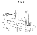
- FIG. 8 is an explanation diagram showing the main part of a boundary part between the support part and the revolving shaft according to exemplary embodiment 1.
- the cartridge body 11 accommodates, in its inside, the agitator 16 serving as an example of an agitating member and an example of a transport member.
- the agitator 16 according to exemplary embodiment 1 has a shaft 21 that serves as an example of a revolving shaft and extends the frontward and rearward directions.
- the shaft 21 according to exemplary embodiment 1 is formed in a cross shape when viewed in a cross section.
- a coupling linkage part 21a is formed which serves as an example of a drive connection section and to which the shaft 14a of the to-be-driven coupling 14 is linked.
- the shaft 21 when developing powder in the cartridge body 11 is to be transported toward the service opening, the shaft 21 according to exemplary embodiment 1 receives the driving transmitted via the to-be-driven coupling 14 and the like, and thereby revolves in the revolution direction indicated by an arrow Ya in FIG. 7A .
- a flow-out opening agitating member 22 is integrally formed that serves as an example of a flow-out opening transport member.
- the flow-out opening agitating member 22 has service opening agitation support parts 22a and 22b that serve as an example of a pair of front and rear flow-out part agitation support parts extending in the radial direction. Then, in FIG. 7C , the service opening agitation support parts 22a and 22b extend in a radial direction with curving toward the downstream relative to the revolution direction Ya of the agitator 16.
- the outer end part in the radial direction is linked by a service opening agitating part 22c that serves as an example of a flow-out part agitating part and that extends in the frontward and rearward directions.
- the rear-side service opening agitation support part 22a according to exemplary embodiment 1 is formed in a shape such as to be bent rearward starting at the center part in the radial direction.
- plural of helical members 23 are formed that serve as an example of a transport member body.
- the helical members 23 are arranged at positions that have predetermined intervals to each other in the axial direction of the shaft 21 and that have a phase deviation of 180 degrees with each other in the revolution direction Ya of the shaft 21.
- Each helical member 23 has a support part 24 extending in a radial direction.
- the support part 24 according to exemplary embodiment 1 extends in a radial direction with curving toward the downstream relative to the revolution direction Ya of the agitator 16.
- the width of the support part 24 is formed longer than one side of the cross of the cross-shaped shaft 21. This increases rigidity and reduces deformation in comparison with a case of being shorter than or equal to one side of the cross.
- transport parts 26 are integrally formed that have the shape of a helix in the axial direction of the shaft 21, that is, the shape of arcs extending along the helix.
- the transport part 26 according to exemplary embodiment 1 has a capability of agitating and transporting developing powder, and hence has the function of an agitating part.
- the transport part 26 has an other end part 26a supported by the support part 24; and one end part 26b located on the side opposite to the arc.
- the one end part 26b is in the form of a free end.
- the transport part 26 and the support part 24 according to exemplary embodiment 1 are supported by the shaft 21 in a cantilever state that the base end part of the support part 24 is supported by the shaft 21.
- its outer diameter is set smaller than the diameter of the inner peripheral surface of the cartridge body 11.
- the transport part 26 is formed in a shape inclined toward the rear side in the axial direction of the shaft 21, that is, toward the downstream in the developing powder transport direction, when viewed from the side surface.
- the central angle about the shaft 21 is set to be 140 degrees or the like. A central angle smaller than or equal to 360 degrees is better, and a central angle greater than or equal to 90 degrees and smaller than or equal to 180 degrees is much better.
- an angle greater than 360 degrees is adopted, at the time of deformation of the support part 24 and the transport part 26 caused by a reactive force from developing powder under transport, an increase is caused in the spread, the deformation, and the inclination of the helix.
- a front-side helical member 31 is provided that serve as an example of an upstream-end transport member.
- the front-side helical member 31 has a front-side inclination support part 32 extending in a radial direction and in the frontward direction from the shaft 21.
- the outer edge of the front-side inclination support part 32 has an upstream agitating part 33 that extends in a helical shape about the shaft 21 and that serves as an example of an upstream transport part.
- the upstream agitating part 33 according to exemplary embodiment has a central angle of 360 degrees.
- the upstream agitating part 33 is linked to the shaft 21 by a first radial direction support part 34 that extends in a radial direction from the shaft 21. Further, at a position where the phase increases by 360 degrees, the upstream agitating part 33 is linked to the shaft 21 by a second radial direction support part 36 that extends in a radial direction from the shaft 21.
- the agitator 16 according to exemplary embodiment 1 is fabricated by integral molding of a resin material having a lower rigidity than metallic materials such as stainless steel.
- the employed resin material may be an arbitrary in accordance with the design, the specification, and the like.
- employable resin materials include PP (polypropylene), HDPE (high-density polyethylene), PA (nylon) (polyamide), ABS (acrylonitrile-butadiene-styrene copolymer), PPE alloy (polyphenylene ether alloy), and POM (polyacetal).
- POM is suitably employed in which deformation caused by a torque load is recovered easily.
- the image forming apparatus U having the above-mentioned configuration according to exemplary embodiment 1, when developing powder is consumed in association with image formation operation, developing powder is supplied from the toner cartridges Ky to Kk.
- the agitator 16 composed of resin arranged in each of the toner cartridges Ky to Kk revolves in the revolution direction Ya for a predetermined time.
- the helix transport part 26 agitates and breaking down the developing powder in the cartridge body 11, and transports the developing powder toward the downstream of the transport direction, that is, toward the rear service opening.
- the developing powder transported to the service opening flows into the image forming apparatus body U1, and is then transported through the inside of the image forming apparatus body U1 so as to be supplied to the developing apparatuses Gy to Gk.
- the transport part 26 when the agitator 16 composed of resin revolves, the transport part 26 receives a force as the reaction of the operation that the transport part 26 pushes and transports the developing powder rearward. Thus, the transport part 26 is deformed.
- a so-called coil-shaped metal agitator having been wound in a helical shape is replaced by that composed of resin, the helix of the agitator is spread owing to its insufficient strength so that the agitator contacts with and rubs against the inner wall surface of the cartridge body 11.
- This causes the problem of an increase in the driving force, that is, a so-called torque, necessary for driving the agitator.
- the contact with the inner wall surface of the cartridge body 11 causes a possibility that the deformation results in permanent bending or breakage.
- a large number of support parts may be provided that extend from the shaft toward the agitator in the radial direction. Nevertheless, even in this case, the spread of the helix cannot sufficiently be suppressed.
- contact with the inner wall surface of the cartridge body 11 causes a high torque.
- the transport part 26 when the transport part 26 receives a reactive force, the transport part 26 formed in a cantilever state and having one end part 26b constructed as a free end is deformed such as to divert or redirect the force.
- an agitator 16 is realized and obtained that does not cause an excessive transport resistance and an excessive driving torque and that has damage resistance, a reduced raw material cost, and a reduced production cost in mass production.
- the agitator 16 that easily redirects the force and hence has a reduced transport resistance, plastic deformation in the transport part 26 at the time of load is reduced.
- the agitator 16 according to exemplary embodiment 1 has improved restorability from deformation caused by a force received at the time of transport of developing powder. That is, a situation is suppressed that plastic deformation in the agitator 16 increases in association with the progresses of time so as to cause a change in the transport performance for developing powder.
- FIG. 9 is an explanation diagram showing deformation and transport performance of the transport part.
- FIG. 9A is an explanation diagram showing deformation and transport performance in a case that the transport part extends toward the downstream as in exemplary embodiment 1.
- FIG. 9B is an explanation diagram showing deformation and transport performance in a case that the transport part extends toward the upstream.
- the arc-shaped transport parts 26 arranged along the helix extend toward the downstream of the developing powder transport direction Yb. If the transport part 26 extends toward the upstream of the developing powder transport direction Yb as shown in FIG. 9B , the free one end part of the transport part 26 is deformed toward the base end as illustrated by a dashed line in FIG. 9B , owing to a force acting from developing powder onto the transport part 26 at the time of agitation and transport.
- the length L2 with deformation is shorter than the length L1 without deformation.
- These lengths L1 and L2 correspond to the effective area for transporting the developing powder to the downstream.
- the transport part 26 is deformed by a force at the time of agitation transport of developing powder, the length L2 with deformation is longer than the length L1 without deformation. Thus, degradation in the transport capability for developing powder is suppressed. Further, in the front surface 26c of the transport part 26, the part that receives the force is inclined relative to the transport direction Yb before the deformation. In contrast, with deformation, the part that receives the force is almost perpendicular to the transport direction Yb. Thus, the capability of pushing and transporting the developing powder is improved.
- the central angle of the arc of the transport part 26 is set to be 140 degrees or the like, and hence does not exceed 360 degrees.
- the amount of deformation in the one end part 26b of the transport part 26 is relatively small so that contact with the inner wall surface of the cartridge body 11 is suppressed. Accordingly, in comparison with a case that the central angle is greater and hence the amount of deformation is larger, noise and a torque increase are reduced that could be caused by the contact of the one end part 26b with the inner peripheral surface of the cartridge body 11.
- the upstream agitating part 33 of 360 degrees is allowed to be arranged, and is supported by plural of support parts 32, 34, and 36 so that the spreading of the helix is suppressed at the time of deformation.
- experiments have been performed concerning deformation in the agitator 16 according to exemplary embodiment 1.
- the experiments are simulations on a computer, that is, so-called computer simulations.
- Example 1-1 is a simulation of the shapes without and with deformation and the von Mises stress acting on each part at each time for a model corresponding to the agitator 16 according to exemplary embodiment 1 in a case that the rear end of the coupling linkage part 21a of the shaft 21 is freely revolvable but its movement in a plane perpendicular to the axial direction is constrained, that the revolution of the right and left outermost edges of each transport part 26 are constrained, and that a revolution load, that is, a torque, of 100 [N•cm] is applied on the shaft 21.
- the breaking stress where the member breaks is set to be 100 [N/mm 2 ].
- Example 1-2 under the condition of Example 1-1, the revolution load is increased until the member breaks. As a result, the revolution load is 300 [N•cm]. Thus, Example 1-2 is a simulation under this condition.
- Example 1-1 parts having a high stress arose in the support part 24 or the transport part 26. However, even in the part on the base end side of the support part 24 where the highest stress is generated, the stress is in the order of 30 MPa to 40 MPa which is approximately half the breaking stress. Thus, no breakage has been concluded. Where the torque is 300 N•cm, breakage has been concluded in the base end part of the support part 24 where the highest stress is generated.
- exemplary embodiment 2 of the present invention is described below.
- components corresponding to those in exemplary embodiment 1 are designated by like numerals. Then, their detailed description is omitted.
- Exemplary embodiment 2 is different from exemplary embodiment 1 in the points described below. However, in the other points, exemplary embodiment 2 is similar to exemplary embodiment 1.
- FIG. 10 is an explanation diagram showing the transport member according to exemplary embodiment 2.
- the first transport part 26 in a cantilever state reduces a driving torque increase and breakage occurrence.
- the second transport parts 126 in a double-end supported state are arranged so that deformation and helix spreading in the second transport part 126 are suppressed.
- the second transport part 126 tends to easily contact with the inner peripheral surface of the cartridge body 11 on the front side where a larger deflection is easily caused when the shaft 21 is deflected at the time of revolution, that is, on the upstream side of the transport direction.
- spreading in the helix of the second transport part 126 is suppressed, and hence a situation that the second transport part 126 contacts the inner peripheral surface of the cartridge body 11 is suppressed in comparison with exemplary embodiment 1.
- exemplary embodiment 3 of the present invention is described below.
- components corresponding to those in exemplary embodiment 1 are designated by like numerals. Then, their detailed description is omitted.
- Exemplary embodiment 3 is different from exemplary embodiment 1 in the points described below. However, in the other points, exemplary embodiment 3 is similar to exemplary embodiment 1.
- FIG. 11A is a perspective view of an explanation diagram showing the agitator according to exemplary embodiment 3.
- FIG. 11B shows a view from an arrow XIIIB direction in FIG. 11A.
- FIG. 11C shows a view from an arrow XIIIC direction in FIG. 11A .
- the support part 224 according to exemplary embodiment 3 extends straight along the radial direction. Further, in correspondence to this, the transport part 226 has a wider central angle than that in exemplary embodiment 1.
- agitator 216 having the above-mentioned configuration according to exemplary embodiment 3 similarly to exemplary embodiment 1, even when the agitator 216 is fabricated from a resin material having a lower strength than metals, an agitator 16 is realized and obtained that does not cause an excessive transport resistance and an excessive driving torque and that has damage resistance, a reduced raw material cost, and a reduced production cost in mass production.
- exemplary embodiment 4 of the present invention is described below.
- components corresponding to those in exemplary embodiment 1 are designated by like numerals. Then, their detailed description is omitted.
- Exemplary embodiment 4 is different from exemplary embodiment 1 in the points described below. However, in the other points, exemplary embodiment 4 is similar to exemplary embodiment 1.
- FIG. 12 is an explanation diagram showing an agitator according to exemplary embodiment 4, and corresponds to FIG. 7C of exemplary embodiment 1.
- a reinforcement part 328 that extends in the radial direction and connects the shaft 21 and the transport part 26 and that serves as an example of a second support part is formed near the support part 24 in a manner of being adjacent to the support part 24.
- the reinforcement part 328 is arranged at a position in the upstream of the revolution direction Ya by 5 degrees or the like in terms of central angle relative to the support part 24.
- the angle may be a value smaller than or equal to 90 degrees relative to the support part 24.
- the transport part 26 is supported by the reinforcement part 328 and the support part 24.
- the entirety strength is increased in comparison with exemplary embodiment 1.
- the agitator 16 is fabricated from a resin material having a lower strength than metals, an agitator 16 is realized and obtained that does not cause an excessive transport resistance and an excessive driving torque and that has damage resistance, a reduced raw material cost, and a reduced production cost in mass production.
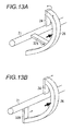
- FIG. 13A is an operation explanation diagram showing a state that a reinforcement part is arranged at a position of 90 degrees relative to the support part for exemplary embodiment 4.
- FIG. 13B is an operation explanation diagram showing a state that a reinforcement part is arranged at a position of 180 degrees relative to the support part.
- FIG.S 15A and 15B members necessary in description are solely illustrated. Further, illustration of these members is simplified.
- the reinforcement part 328 is arranged at a position of 90 degrees or smaller relative to the support part 24. Since the reinforcement part 328 is arranged at a position of 90 degrees or smaller as shown in FIG. 13A , when the transport part 26 receives a reactive force from the developing powder, that is, a force along the axial direction of the shaft 21, in accordance with the deformation of the transport part 26 inclined in the axial direction, the support part 24 and the reinforcement part 328 receive a force for twisting them in the similar direction. This increases the resistance against deformation, and hence reduces the deformation. If the reinforcement part is formed at a position of 180 degrees as shown in FIG.
Landscapes
- Physics & Mathematics (AREA)
- General Physics & Mathematics (AREA)
- Dry Development In Electrophotography (AREA)
Applications Claiming Priority (1)
| Application Number | Priority Date | Filing Date | Title |
|---|---|---|---|
| JP2008284697A JP4710959B2 (ja) | 2008-11-05 | 2008-11-05 | 粉体搬送用の搬送部材、現像剤収容容器および画像形成装置 |
Publications (1)
| Publication Number | Publication Date |
|---|---|
| EP2184650A1 true EP2184650A1 (fr) | 2010-05-12 |
Family
ID=41508933
Family Applications (1)
| Application Number | Title | Priority Date | Filing Date |
|---|---|---|---|
| EP09163178A Withdrawn EP2184650A1 (fr) | 2008-11-05 | 2009-06-18 | Élément de transport pour transport de poudres, récipient d'accessoire de poudre de développement, et appareil de formation d'images |
Country Status (6)
| Country | Link |
|---|---|
| US (1) | US8478172B2 (fr) |
| EP (1) | EP2184650A1 (fr) |
| JP (1) | JP4710959B2 (fr) |
| KR (1) | KR101119944B1 (fr) |
| CN (1) | CN101738905B (fr) |
| AU (1) | AU2009202419B2 (fr) |
Cited By (1)
| Publication number | Priority date | Publication date | Assignee | Title |
|---|---|---|---|---|
| EP2587315A1 (fr) * | 2011-10-24 | 2013-05-01 | Kyocera Document Solutions Inc. | Récipient de stockage de révélateur et appareil de formation dýimages l'utilisant |
Families Citing this family (8)
| Publication number | Priority date | Publication date | Assignee | Title |
|---|---|---|---|---|
| JP4947098B2 (ja) * | 2009-07-02 | 2012-06-06 | 富士ゼロックス株式会社 | 搬送具、現像剤収容器及び画像形成装置 |
| JP5391893B2 (ja) * | 2009-07-16 | 2014-01-15 | 富士ゼロックス株式会社 | 搬送具、現像剤収容器及び画像形成装置 |
| JP5630225B2 (ja) | 2010-11-12 | 2014-11-26 | 富士ゼロックス株式会社 | 現像剤の収容容器および画像形成装置 |
| US9250571B2 (en) * | 2013-03-12 | 2016-02-02 | Xerox Corporation | Method and apparatus for filling a toner container useful in printing |
| JP6638640B2 (ja) | 2016-12-22 | 2020-01-29 | 京セラドキュメントソリューションズ株式会社 | トナー容器及び画像形成装置 |
| JP6575502B2 (ja) | 2016-12-22 | 2019-09-18 | 京セラドキュメントソリューションズ株式会社 | トナー容器及び画像形成装置 |
| AU2017272313B2 (en) * | 2016-12-09 | 2019-01-17 | Kyocera Document Solutions Inc. | Toner case and image forming apparatus |
| JP7275680B2 (ja) * | 2019-03-13 | 2023-05-18 | 富士フイルムビジネスイノベーション株式会社 | 搬送部材、粉体搬送装置、粉体回収容器、画像形成装置 |
Citations (13)
| Publication number | Priority date | Publication date | Assignee | Title |
|---|---|---|---|---|
| US4610068A (en) * | 1985-07-17 | 1986-09-09 | Eastman Kodak Company | Method for forming a ribbon blender |
| US4887132A (en) * | 1984-04-06 | 1989-12-12 | Eastman Kodak Company | Electrographic development apparatus having a ribbon blender |
| US4956675A (en) * | 1988-12-23 | 1990-09-11 | Eastman Kodak Company | Ribbon blender for a development apparatus with self adjusting inner and outer ribbons |
| US5228775A (en) * | 1989-05-04 | 1993-07-20 | Blentech Corporation | Reversing blender agitators |
| JPH10247009A (ja) | 1997-03-04 | 1998-09-14 | Fuji Xerox Co Ltd | 現像剤供給装置 |
| JP2000305344A (ja) | 1999-04-20 | 2000-11-02 | Canon Inc | 現像剤収容装置、現像装置及びこれらを備える画像形成装置 |
| JP2002268344A (ja) | 2001-03-06 | 2002-09-18 | Fuji Xerox Co Ltd | 現像剤補給装置 |
| US20020150410A1 (en) * | 2001-03-30 | 2002-10-17 | Canon Kabushiki Kaisha | Developer carrying member, developer replenishment container and image forming apparatus |
| JP2004252184A (ja) | 2003-02-20 | 2004-09-09 | Fuji Xerox Co Ltd | 画像形成装置及びカートリッジユニット装着装置 |
| JP2005134452A (ja) | 2003-10-28 | 2005-05-26 | Fuji Xerox Co Ltd | トナー補給装置及び画像形成装置 |
| JP2005181515A (ja) | 2003-12-17 | 2005-07-07 | Fuji Xerox Co Ltd | 画像形成装置 |
| JP2006053446A (ja) | 2004-08-16 | 2006-02-23 | Ricoh Co Ltd | トナーボトル及び画像形成装置 |
| US20080240789A1 (en) * | 2007-03-28 | 2008-10-02 | Fuji Xerox Co., Ltd. | Rotator for powder conveyance and toner cartridge |
Family Cites Families (7)
| Publication number | Priority date | Publication date | Assignee | Title |
|---|---|---|---|---|
| JP3319844B2 (ja) * | 1993-12-27 | 2002-09-03 | 株式会社リコー | 現像剤撹拌装置 |
| TW342105U (en) * | 1994-07-15 | 1998-10-01 | Ricoh Co Ltd | Toner cartridge for a developing device included in an image forming apparatus |
| US5835828A (en) * | 1995-06-15 | 1998-11-10 | Mita Industrial Co., Ltd. | Stirrer and toner cartridge equipped with the stirrer |
| JP3427806B2 (ja) | 2000-02-16 | 2003-07-22 | 富士ゼロックス株式会社 | 液体現像電子写真印刷装置の感光体クリーニング方法 |
| JP2004307139A (ja) * | 2003-04-07 | 2004-11-04 | Takahata Seiko Kk | 粉流体らせん搬送器 |
| JP2006267680A (ja) * | 2005-03-24 | 2006-10-05 | Canon Inc | 現像剤補給容器及び現像剤補給装置 |
| JP2008241880A (ja) * | 2007-03-26 | 2008-10-09 | Canon Inc | 画像形成装置及びトナー補給方法 |
-
2008
- 2008-11-05 JP JP2008284697A patent/JP4710959B2/ja not_active Expired - Fee Related
-
2009
- 2009-05-15 US US12/466,824 patent/US8478172B2/en active Active
- 2009-06-17 AU AU2009202419A patent/AU2009202419B2/en active Active
- 2009-06-17 KR KR1020090053708A patent/KR101119944B1/ko active IP Right Grant
- 2009-06-18 CN CN200910147373.0A patent/CN101738905B/zh active Active
- 2009-06-18 EP EP09163178A patent/EP2184650A1/fr not_active Withdrawn
Patent Citations (13)
| Publication number | Priority date | Publication date | Assignee | Title |
|---|---|---|---|---|
| US4887132A (en) * | 1984-04-06 | 1989-12-12 | Eastman Kodak Company | Electrographic development apparatus having a ribbon blender |
| US4610068A (en) * | 1985-07-17 | 1986-09-09 | Eastman Kodak Company | Method for forming a ribbon blender |
| US4956675A (en) * | 1988-12-23 | 1990-09-11 | Eastman Kodak Company | Ribbon blender for a development apparatus with self adjusting inner and outer ribbons |
| US5228775A (en) * | 1989-05-04 | 1993-07-20 | Blentech Corporation | Reversing blender agitators |
| JPH10247009A (ja) | 1997-03-04 | 1998-09-14 | Fuji Xerox Co Ltd | 現像剤供給装置 |
| JP2000305344A (ja) | 1999-04-20 | 2000-11-02 | Canon Inc | 現像剤収容装置、現像装置及びこれらを備える画像形成装置 |
| JP2002268344A (ja) | 2001-03-06 | 2002-09-18 | Fuji Xerox Co Ltd | 現像剤補給装置 |
| US20020150410A1 (en) * | 2001-03-30 | 2002-10-17 | Canon Kabushiki Kaisha | Developer carrying member, developer replenishment container and image forming apparatus |
| JP2004252184A (ja) | 2003-02-20 | 2004-09-09 | Fuji Xerox Co Ltd | 画像形成装置及びカートリッジユニット装着装置 |
| JP2005134452A (ja) | 2003-10-28 | 2005-05-26 | Fuji Xerox Co Ltd | トナー補給装置及び画像形成装置 |
| JP2005181515A (ja) | 2003-12-17 | 2005-07-07 | Fuji Xerox Co Ltd | 画像形成装置 |
| JP2006053446A (ja) | 2004-08-16 | 2006-02-23 | Ricoh Co Ltd | トナーボトル及び画像形成装置 |
| US20080240789A1 (en) * | 2007-03-28 | 2008-10-02 | Fuji Xerox Co., Ltd. | Rotator for powder conveyance and toner cartridge |
Cited By (1)
| Publication number | Priority date | Publication date | Assignee | Title |
|---|---|---|---|---|
| EP2587315A1 (fr) * | 2011-10-24 | 2013-05-01 | Kyocera Document Solutions Inc. | Récipient de stockage de révélateur et appareil de formation dýimages l'utilisant |
Also Published As
| Publication number | Publication date |
|---|---|
| AU2009202419A1 (en) | 2010-05-20 |
| CN101738905B (zh) | 2016-09-21 |
| AU2009202419B2 (en) | 2011-02-17 |
| JP2010113094A (ja) | 2010-05-20 |
| JP4710959B2 (ja) | 2011-06-29 |
| KR20100050377A (ko) | 2010-05-13 |
| US8478172B2 (en) | 2013-07-02 |
| CN101738905A (zh) | 2010-06-16 |
| KR101119944B1 (ko) | 2012-03-15 |
| US20100111574A1 (en) | 2010-05-06 |
Similar Documents
| Publication | Publication Date | Title |
|---|---|---|
| EP2184650A1 (fr) | Élément de transport pour transport de poudres, récipient d'accessoire de poudre de développement, et appareil de formation d'images | |
| US9740140B2 (en) | Developer stirring member and image forming apparatus | |
| JP4208645B2 (ja) | 現像剤補給容器 | |
| JP2008268445A (ja) | 粉体搬送部材及びこれを用いた粉体搬送装置、枠体、画像形成装置、並びに粉体搬送部材の製造装置 | |
| US20080143038A1 (en) | Paper separating device, fixing device, paper conveyance device, and image forming apparatus | |
| JP2001194882A (ja) | トナー補給装置 | |
| JP4322931B2 (ja) | 現像装置及び画像形成装置 | |
| JP2009145610A (ja) | 現像装置および画像形成装置 | |
| CN110874032B (zh) | 显影剂收容构件以及图像形成装置 | |
| JP5582452B2 (ja) | トナーの搬送機構および画像形成装置 | |
| JP5391893B2 (ja) | 搬送具、現像剤収容器及び画像形成装置 | |
| JP5103883B2 (ja) | 回収装置及び画像形成装置 | |
| JP2006139084A (ja) | プロセスカートリッジ及びこれを備える画像形成装置 | |
| CN109426106B (zh) | 图像形成设备 | |
| JP6664139B2 (ja) | 現像装置 | |
| US10031470B2 (en) | Developer container that reduces coming-off of rotating member and image forming apparatus that includes the same | |
| JP4947098B2 (ja) | 搬送具、現像剤収容器及び画像形成装置 | |
| JP6620713B2 (ja) | 現像剤容器及び画像形成装置 | |
| JP2016173560A (ja) | 画像形成ユニット、及び画像形成装置 | |
| JP2009258514A (ja) | 粉体搬送装置及びこれを搭載した画像形成装置 | |
| JP6706140B2 (ja) | トナーカートリッジ | |
| JP6598585B2 (ja) | 回収トナー搬送装置 | |
| JP2001134095A (ja) | 現像装置及びそれを用いた電子写真装置 | |
| JP2009258513A (ja) | 粉体搬送装置及びこれを搭載した画像形成装置 |
Legal Events
| Date | Code | Title | Description |
|---|---|---|---|
| PUAI | Public reference made under article 153(3) epc to a published international application that has entered the european phase |
Free format text: ORIGINAL CODE: 0009012 |
|
| 17P | Request for examination filed |
Effective date: 20090713 |
|
| AK | Designated contracting states |
Kind code of ref document: A1 Designated state(s): AT BE BG CH CY CZ DE DK EE ES FI FR GB GR HR HU IE IS IT LI LT LU LV MC MK MT NL NO PL PT RO SE SI SK TR |
|
| STAA | Information on the status of an ep patent application or granted ep patent |
Free format text: STATUS: THE APPLICATION HAS BEEN WITHDRAWN |
|
| 18W | Application withdrawn |
Effective date: 20140117 |