EP2177270B1 - Schrottschere - Google Patents
Schrottschere Download PDFInfo
- Publication number
- EP2177270B1 EP2177270B1 EP08791064.2A EP08791064A EP2177270B1 EP 2177270 B1 EP2177270 B1 EP 2177270B1 EP 08791064 A EP08791064 A EP 08791064A EP 2177270 B1 EP2177270 B1 EP 2177270B1
- Authority
- EP
- European Patent Office
- Prior art keywords
- scrap
- hydraulic ram
- mouth
- shear
- stand
- Prior art date
- Legal status (The legal status is an assumption and is not a legal conclusion. Google has not performed a legal analysis and makes no representation as to the accuracy of the status listed.)
- Not-in-force
Links
Images
Classifications
-
- B—PERFORMING OPERATIONS; TRANSPORTING
- B23—MACHINE TOOLS; METAL-WORKING NOT OTHERWISE PROVIDED FOR
- B23D—PLANING; SLOTTING; SHEARING; BROACHING; SAWING; FILING; SCRAPING; LIKE OPERATIONS FOR WORKING METAL BY REMOVING MATERIAL, NOT OTHERWISE PROVIDED FOR
- B23D25/00—Machines or arrangements for shearing stock while the latter is travelling otherwise than in the direction of the cut
- B23D25/14—Machines or arrangements for shearing stock while the latter is travelling otherwise than in the direction of the cut without regard to the exact dimensions of the resulting material, e.g. for cutting-up scrap
-
- B—PERFORMING OPERATIONS; TRANSPORTING
- B23—MACHINE TOOLS; METAL-WORKING NOT OTHERWISE PROVIDED FOR
- B23D—PLANING; SLOTTING; SHEARING; BROACHING; SAWING; FILING; SCRAPING; LIKE OPERATIONS FOR WORKING METAL BY REMOVING MATERIAL, NOT OTHERWISE PROVIDED FOR
- B23D31/00—Shearing machines or shearing devices covered by none or more than one of the groups B23D15/00 - B23D29/00; Combinations of shearing machines
- B23D31/008—Cutting-up scrap
-
- B—PERFORMING OPERATIONS; TRANSPORTING
- B30—PRESSES
- B30B—PRESSES IN GENERAL
- B30B9/00—Presses specially adapted for particular purposes
- B30B9/32—Presses specially adapted for particular purposes for consolidating scrap metal or for compacting used cars
- B30B9/326—Presses specially adapted for particular purposes for consolidating scrap metal or for compacting used cars provided with shearing means for the scrap metal, or adapted to co-operate with a shearing machine
Definitions
- the present invention relates to a scrap shearing machine according to the preamble of claim 1, for shearing a long-rigid metal scrap into a plurality of short scrap pieces. More particularly, the present invention relates to a scrap shearing machine comprising a guillotine-type straight-blade shear-stand, an open feed channel which forms a parallelepiped space having a width greater than that of the mouth of the shear-stand, a side hydraulic ram for squashing the metal scrap sideways in the feed channel before feeding it into the mouth of the shear-stand, and a feeder for feeding the metal scrap into the mouth of the shear-stand after the scrap has been squashed sideways by the side hydraulic ram in the feed channel, wherein said side hydraulic ram is situated adjacent to the mouth of the shear-stand and is adapted to squash the metal scrap in front of the mouth only at a certain limited longitudinal section which is shorter than the overall length of the scrap in the longitudinal direction of the feed channel so as to squash the metal scrap to a final width no greater
- Patent Document 1 discloses a scrap shearing machine of this kind according to the preamble of claim 1 for handling scrap in the form of cylindrical containers and pipes of large-diameter, in which the scrap is squashed from the side to reduce its width and then sheared into short pieces by means of a guillotine-type straight-blade shear-stand.
- Patent Document 1 United States Patent No. 3,945,315
- This known scrap shearing machine uses an open feed channel which is wider than the mouth of the shears.
- a side hydraulic ram for squashing the scrap sideways to reduce its width before feeding it into the comparatively narrow mouth of the shears.
- the side hydraulic ram comprises a main ram and an auxiliary ram.
- the auxiliary ram can be operated in advance independently of the main ram.
- the working face of the auxiliary ram is situated adjacent to the mouth of the shears and is shorter than the working face of the main ram in the feed channel.
- the scrap shearing machine also comprises a down thrust plate provided in a pivoted manner which covers the full length of the channel along a sidewall of the channel on one side to which the side hydraulic ram is opposed.
- the down thrust plate is driven by a hydraulic cylinder which is pivoted by a pin on an arm fixed to the machine frame at the one side for holding down the scrap to prevent it from bulging upward along the full length of the channel before the scrap enters the mouth of the shears.
- the box-shaped feed channel also must be constructed to have a suitably long, wide and deep dimension for being able to handle such a large-long metal scrap.
- Another scrap pressing machine is for example disclosed in JP 02024016 A .
- a hydraulic scrap share having a multiple segmented shearing blade configuration is for example disclosed in United States Patent 4,881,459 .
- the main object of the present invention is to provide a scrap shearing machine suitable for shearing relatively large, long, and rigid metal scrap, in particular, discarded land vehicles such as railroad coaches including a freight car and a passenger car, large-sized automobiles including a limousine and a heavy-duty truck or architectural scrap including section steels, into a plurality of short scrap pieces.
- discarded land vehicles such as railroad coaches including a freight car and a passenger car, large-sized automobiles including a limousine and a heavy-duty truck or architectural scrap including section steels
- the object can be achieved by the scrap shearing machine according to claim one.
- Advantageous embodiments may be taken from the dependent claims.
- the scrap shearing machine is suitably used for shearing, into a plurality of short scrap pieces, relatively large, long, and rigid metal scraps, in particular, discarded land vehicles such as railroad coaches including a freight car and a passenger car, large-sized automobiles including a limousine and a heavy-duty truck and architectural scrap including section steels.
- the metal scrap Upon placed in the feed channel, the metal scrap is squashed in front of the mouth of the shear-stand only at a certain limited longitudinal section which is shorter than the overall length of the scrap, by the downward hydraulic ram and side hydraulic ram respectively equipped to one end of the open feed channel which is wider than the mouth of the shear-stand, to a cross section dimension having a final height no greater than the inside height of the mouth and a final width no greater than the inside width of the mouth. Therefore, the driving torque of the hydraulic rams is obviously reduced as compared to the case of the conventional scrap shearing machine technology, and each of the rams can be driven by a relatively small diameter hydraulic power cylinder.
- Respective drive systems of the straight-blade shear-stand, the feeder, the side hydraulic ram, and the downward hydraulic ram are supervised and controlled by the control unit in accordance with a predetermined operation sequence.
- the downward hydraulic ram is driven by the vertical hydraulic cylinder and the side hydraulic ram is driven by the horizontal hydraulic cylinder.
- respective linear guides which slidably fit with each other are provided.
- the downward hydraulic ram is designed to downwardly squash the metal scrap in front of the mouth only at a certain limited longitudinal section which is shorter than the overall length of the scrap in the longitudinal direction of the feed channel prior to squashing operation of the side hydraulic ram so as to squash the metal scrap to a final height no greater than the inside height of the mouth of the shear-stand.
- the drive system of the downward ram may be constituted by an electrically driven mechanism, it is preferably for the drive system to be composed of a hydraulic piston-cylinder unit. It is advantageous for the downward hydraulic ram to be provided with an auxiliary weight for assisting the downward squashing force by the vertical hydraulic cylinder.
- the side hydraulic ram is designed to be operated after completion of the squashing operation by the downward hydraulic ram to squash the metal scrap sideways in front of the mouth only at a certain limited longitudinal section which is already squashed downwardly by the downward hydraulic ram and is shorter than the overall length of the scrap in the longitudinal direction of the feed channel so as to squash the metal scrap to a final width no greater than the width of the mouth of the shear-stand.
- the drive system of the side ram may be constituted by an electrically driven mechanism, it is preferably for the drive system to be composed of a hydraulic piston-cylinder unit. Needless to say, in order to apply a stronger squashing force, a plurality of horizontal hydraulic cylinders may drive a single side ram.
- the contour shape of the transverse cross section of the metal scrap squashed by the downward and side hydraulic rams may preferably have a dimension smaller than the inside dimension of the mouth of the shear-stand. This is because when the compression state by each of the hydraulic rams is released, the squashed portion expands due to a spring-back action and this expansion gradually increases. Taking such expansion by the spring-back action into consideration, the final stroke of squashing by each of the hydraulic rams may preferably reach a position at which the transverse cross-sectional dimension of the squashed portion of the metal scrap becomes smaller than the inside dimension of the mouth of the shear-stand that much.
- control unit has functions for variably set conditions, such as the driving torque of downward and side hydraulic rams, compression holding time, and the number of times of re-compression.
- the feeder comprises a hydraulic pusher which performs reciprocating movement from a tail end face of the feed channel toward the mouth of the shear-stand, and vice versa.
- the feeder is not limited to the hydraulic pusher.
- Other feeder machines which feed, toward the mouth of the blade shear-stand, the metal scrap placed in the feed channel, such as an electric-powered lead screw and an endless-chain conveyor, may be used.
- the scrap shearing machine further comprises a pair of sheathing boards which extend upward along both the sidewalls of the feed channel.
- the sheathing boards extend along both the sidewalls of the feed channel upward, and each of their upper edges at least reaches a height equivalent to the initial standby position (ascent position) of the downward hydraulic ram.
- a frame for supporting the downward hydraulic ram and the hydraulic cylinder for driving it also is provided with closing walls which cover both the side faces of the frame. While the metal scrap placed in the feed channel is being squashed particularly by the side hydraulic ram, the sheathing boards and the closing walls prevent the metal scrap from escaping out of the feed channel. As in the case of the sheathing boards, it will also serve the purpose if the closing walls cover at least a region of both the sides of the frame lower than an initial standby position (ascent position) of the downward hydraulic ram.
- the scrap shearing machine of the present invention comprises the control unit, which supervises and controls respective drive systems of the straight-blade shear-stand, the feeder, the side hydraulic ram, and the downward hydraulic ram in accordance with a predetermined operation sequence.
- control unit includes a sequence controller.
- sequence controller performs steps, namely, a control sequence in which the steps are sequentially repeated as follows:
- the control unit starts controlling the operation of the scrap shearing machine.
- the worker may visually make sure that the metal scrap has been carried in and manipulate the start switch.
- the operation control may be automatically started when the metal scrap of predetermined weight has been carried into the feed channel.
- the control unit drives the feeder to move the metal scrap until the front end of the metal scrap in the feed channel reaches the mouth of the shear-stand.
- the driving torque of the feeder or the pressure in the hydraulic circuit of the hydraulic feeder is measured and monitored by the control unit associated with a sensor. When the measured value from the sensor exceeds the predetermined threshold value, it is judged that the front end of the metal scrap has reached the mouth of the shear-stand, and a corresponding signal is initiated by the control unit. Then, a subsequent downward press step is started.
- the downward hydraulic ram In the downward press step, by the downward hydraulic ram, only a certain limited longitudinal section of the metal scrap in front of the mouth is squashed downward to a final height which is not greater than the inside height of the mouth of the shear-stand. In this regard, an operation of the downward hydraulic ram is given an interlock so as to ensure the absence of the feeder and side hydraulic ram in the descending region, thereby the mutual mechanical interference between them is avoided.
- the descending stroke end of the downward hydraulic ram corresponds to a height level of a top face of the side hydraulic ram. Because of the reason already described, the descending stroke end is located below the upper edge level of the mouth of the shear-stand.
- the downward hydraulic ram arrives at the descendent stroke end, the downward hydraulic ram is latched to that position, and completion of the latching will be detected by, for example, a limit switch.
- the detection signal by the limit switch is given to the control unit thereby the control sequence is changed to the following side press step.
- the side press step only the limited longitudinal section of the metal scrap in front of the mouth, which is held in a state where it is already squashed downwardly by the downward hydraulic ram, is squashed sideways to a final width no greater than the inside width of the mouth of the shear-stand.
- the operation of the side hydraulic ram is interlocked for ensuring the absence of the feeder in the moving range of the side hydraulic ram thereby the mutual mechanical interference between the feeder and the side hydraulic ram is avoided.
- the forward stroke end of the side hydraulic ram in the side press step is selected to an inner position of the inside width of the mouth of the shear-stand so that, even if the expansion due to the spring-back of the compressed metal scrap occurs when the compression by the side hydraulic ram is released, the width dimension of the squashed portion still stays within the inside width of the mouth of the shear-stand.
- the control unit is adapted to monitor the arrival of the side hydraulic ram at its forward stroke end during the side press step.
- a detection signal is given from another limit switch to the control unit, thereby the side hydraulic ram and the downward hydraulic ram are sequentially returned to respective initial positions. Consequently, the control sequence is changed to the next feeding step which is followed by the shearing step.
- the feeder is driven, and the metal scrap in the feed channel is fed from its front end into the mouth of the shear-stand.
- the driving torque of the feeder or the pressure in the hydraulic circuit thereof is measured and monitored by the control unit with the associating sensor.
- the control unit In the case where the front end of the feeder has not reached the stroke ranges of the downward hydraulic ram and the side hydraulic ram, when the detection signal of the sensor exceeds the predetermined threshold value, it is judged by the control unit that an uncompressed portion of the metal scrap has reached the mouth of the shear-stand. Then, the driving of the feeder is suspended by the control unit having received the sensor signal, and the control sequence is resumed from the downward press step.
- the feed amount of the metal scrap by the feeder is measured during the shearing step and the control sequence may be resumed from the downward press step when the measured feed amount has reached the length of the limited longitudinal section.
- the function of the limit switches can be substituted with a software program.
- the front end portion of the metal scrap which is squashed downward and sideways and being fed into the mouth of the shear-stand by the feeder, is cut into a short scrap piece by upper and lower blades of the scrap shears while being sequentially clamped by a hydraulic stamper installed in front of the scrap shears within the shear-stand. Every time one short scrap piece is cut out, a corresponding signal is given to the control unit. Thereby, the clamping by the hydraulic stamper is released and the upper blade of the shears is returned to its ascent position. Subsequently, the remaining metal scrap is fed forward by the feeder. In a similar way, the next short scrap piece is cut out from the remaining metal scrap.
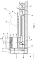
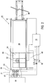
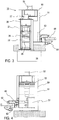
- the scrap shearing machine 10 comprises an open feed channel 30 having two opposite sidewalls to form a rectangular parallelepiped space, a guillotine-type straight-blade shear-stand 20 at one end of the feed channel and having scrap shears and a mouth 22 narrower than the normal width of the feed channel 30 between said sidewalls, a side hydraulic ram 63 for moving at least one of said sidewalls towards the other of said sidewalls whereby the metal scrap 35 placed in the feed channel 30 can be squashed sideways before feeding the metal scrap into the mouth of the shear-stand, and a feeder 40 for feeding the metal scrap 35 into the mouth 22 of the shear-stand 20 after said metal scrap has been squashed sideways by the side hydraulic ram in the feed channel 30.
- the scrap shearing machine 10 further comprises a downward hydraulic ram 53 and a control unit 70.
- the side hydraulic ram 63 is situated adjacent to the mouth 22 of the shear-stand. Moreover, the side hydraulic ram 63 is adapted to squash the metal scrap 35 in front of the mouth 22 only at a certain limited longitudinal section which is shorter than the overall length of the scrap in the longitudinal direction of the feed channel 30 so as to squash the metal scrap to a final width no greater than the inside width of the mouth 22 of the shear-stand.
- the downward hydraulic ram 53 is associated with said side hydraulic ram 63 and situated adjacent to the mouth 22 of the shear-stand.
- the downward hydraulic ram 53 is adapted to downwardly squash the metal scrap 35 in front of the mouth only at a certain limited longitudinal section which is shorter than the overall length of the scrap in the longitudinal direction of the feed channel 30 prior to squashing operation of the side hydraulic ram 63 so as to squash the metal scrap 35 to a final height no greater than the inside height of the mouth 22 of the shear-stand.
- Respective drive systems of the shear-stand 20, of the feeder 40, of the side hydraulic ram 63, and of the downward hydraulic ram 53 are associated with the control unit 70 for supervising and controlling them in a predetermined operation sequence.
- the scrap shearing machine is suited to shear relatively large, long, and rigid metal scrap, in particular, discarded land vehicles such as railroad coaches including a freight car and a passenger car, large-sized automobiles including a limousine and a heavy-duty truck or architectural scrap including section steels, into a plurality of short scrap pieces.
- non-metallic portions are preferably removed from these metal scraps.
- a seat or interior materials composed of cloth, seat covers, urethane foam, etc. and tires, glass, a plastic bumper, a dashboard, etc. are removed. These non-metallic materials are separated by tearing from the body, etc.
- parts made up of spring steel are removed in advance so as not to give an excessive load to the drive systems of the downward hydraulic ram and side hydraulic ram.
- the straight-blade shear-stand 20 has a passage formed inside its double housing frame 21.
- the entrance of the passage forms the mouth 22 of the shear-stand opened in one end face of the feed channel 30.
- the exit on the other side is opened in a pit 28 for receiving the short scrap pieces after shearing.
- a hydraulic stamper 24 driven by a vertical hydraulic cylinder 23, for holding down the squashed metal scrap and clamping it just before the shears during shearing.
- the shears are composed of a stationary lower blade 25 arranged on the exit side adjacent to the hydraulic stamper 24 and an upper blade 26 arranged to cooperate with the lower blade 25 to shear the metal scrap into a short scrap piece 36.
- the upper blade 26 is driven by a main hydraulic cylinder 27 which is installed vertically on the frame 21.
- the short scrap piece 36 sheared in the shear-stand 20 falls into the pit 28 provided adjacent to the exit of the shear-stand 20 and is stored there temporarily.
- the bottom floor of the pit 28 is lower than the upper edge of the lower blade of the shear-stand 20. Moreover, the bottom floor is inclined such that as it departs from the shear-stand, it gradually gets deeper. Therefore, inside the pit 28, the sheared short scrap piece 36 moves away by itself from the proximity of the exit of the shear-stand 20, and it does not stay near the exit.
- the feed channel 30 is completely opened upward.
- the downward hydraulic ram is at an ascent position (initial position), the space below it is also opened with enough height for receiving the unsquashed metal scrap.
- a pair of sheathing boards 31 extending upward along both the sidewalls are provided.
- the feeder 40 comprises a hydraulic pusher.
- the pusher ram 41 forms part of or all of the tail-end wall face of the feed channel 30.
- numeral 42 denotes a piston rod of the hydraulic cylinder for allowing the pusher ram 41 to reciprocate in the longitudinal direction of the feed channel.
- the downward hydraulic ram 53 is driven by the vertical hydraulic cylinder 52 along the true vertical direction which is the same as the working directions of the upper blade and the hydraulic stamper, and the cylinder 52 and the ram 53 constitute a downward hydraulic press unit 50.
- the downward hydraulic ram 53 and the hydraulic cylinder 52 are supported by a double housing frame 51 which is provided to bridge both the sidewalls of the feed channel 30.
- the downward hydraulic ram 53 has the same width dimension as the inside width of the feed channel 30.
- the side hydraulic ram 63 forms one inner wall face covering a certain limited region close to the mouth of the shear-stand in the feed channel 30, and is driven by the horizontal hydraulic cylinder 62 for the squashing operation from that side.
- the side hydraulic ram 63 and the hydraulic cylinder 62 constitute a side press unit 60.
- a closing wall which covers three faces (both the sides faces and the back end face toward the shear-stand) except the feeder 40 side above the upper edge of both the sidewalls of the feed channel 30.
- the control unit 70 includes a sequence controller. According to the preset control sequence, the control unit supervises and controls operations, as a whole, of the hydraulic cylinder 23 and the main hydraulic cylinder 27 of the shear-stand 20, the drive cylinder 42 of the feeder 40, the hydraulic cylinder 52 for the downward hydraulic ram 50, and the hydraulic cylinder 62 of the side press unit 60.
- the control sequence by the sequence controller includes:
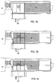
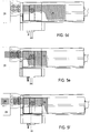
- Figs. 5a to 5f states of the scrap shearing machine in various steps of operation according to the control sequence are shown.
- Fig. 5a as shown by parallel crossed lines, a large metal scrap 35 is placed in the feed channel 30. When this is checked by a worker, a start command is given to the control unit 70.
- the metal scrap 35 is pushed toward the shear-stand 20 through the initial operation of the feeder 40 by the control unit 70.
- the change in the driving torque (load torque) of the feeder 40 when the front end of the metal scrap comes in contact with the end surface of the feed channel in front of the mouth 22 of the shear-stand 20 is detected by a load sensor. Based on the detection result, the control sequence by the control unit 70 is changed to the downward press step, and the downward press step by the downward hydraulic ram 53 is started.
- Fig. 5c the downward press step by the downward hydraulic ram 53 is completed. Subsequently, the side press step by the side hydraulic ram 63 is performed. The side press step is completed when the side hydraulic ram 63 reaches the stroke end set in advance. When a signal indicating the completion of the side press step is given to the control unit 70, the side hydraulic ram 63 and the downward hydraulic ram 53 are sequentially returned to respective initial positions.
- each hydraulic ram has been returned to its initial position and the feeding step by the feeder 40 restart.
- the moving distance of the pusher ram 41 is measured and counted during the feeding step.
- a predetermined threshold value which is preset in accordance with the design specification of the shear-stand 20
- the squashed front portion of the metal scrap 35 has exceeded the position of the blades 25 and 26 by the predetermined length corresponding to a dimension of the short scrap piece to be sheared ( Fig. 5e ).
- a corresponding signal is given to the control unit 70 and, thereby, the hydraulic stamper 24 of the shear-stand 20 is activated and the squashed front portion of the metal scrap is downwardly clamped in close proximity to the shear blades.
- the main hydraulic cylinder 27 is driven to execute shearing ( Fig. 5f ).
- feeding of the metal scrap by the feeder 40 and cutting of the metal scrap into the short scrap piece 36 by the shear-stand 20 are repeated.
- the sequential operation is repeated again from the feeding step followed by the downward and sideway press steps until the full length of the metal scrap 35 placed in the feed channel 30 is sheared into the short pieces.
- Figs. 5a to 5f show that the shearing step is performed about three times for each of the downward and side press steps, the present invention is not limited thereto, and any modification may be adopted within the scope of the invention.
- the short scrap piece 36 emerged from the exit of the shear-stand is substantially in the shape of a cube, which can efficiently be transferred by the motor truck or railroad freight car.
- the short scrap pieces are transported to a recycling facility to efficiently sort and collect the resource materials.
Claims (9)
- Schrottschere zum Scheren von Metallabfall in eine Vielzahl von kurzen Schrottstücken, umfassend einen Zufuhrkanal mit zwei einander gegenüberliegenden Seitenwänden, die einen rechteckigen quaderförmigen Raum bilden, einen guillotineartigen Scherstand (20) für grade Klingen an einem Ende des Zufuhrkanals mit Schrottscheren und einem Maul (22), welches enger als die normale Breite des Zufuhrkanals (30) zwischen den Seitenwänden ist, einen seitlichen hydraulischen Stempel (63) zur Bewegung wenigstens einer der Seitenwände in Richtung auf die andere der Seitenwände, wobei der Metallschrott (35), der in dem Zufuhrkanal (30) angeordnet ist, seitwärts zerquetscht wird, bevor dieser dem Maul des Scherstands zugeführt wird, und eine Zuführung (40) zum Zuführen des Metallschrotts (35) in das Maul (22) des Scherstands (20), nachdem der Metallschrott seitwärts durch den seitlichen hydraulischen Stempel in den Zufuhrkanal (30) gequetscht wurde, wobei der seitliche hydraulische Stempel (63) nahe des Mauls (22) des Scherstandes angeordnet ist und dazu ausgebildet ist, dem Metallschrott vor dem Maul nur in einem bestimmten begrenzten Längsabschnitt zu zerquetschen, welcher Abschnitt kürzer als die Gesamtlänge des Schrotts in Längsrichtung des Zufuhrkanals (30) ist, sodass der Metallschrott auf eine Endbreite zerquetscht wird, die nicht größer als die lichte Weite des Mauls (22) ist, dadurch gekennzeichnet, dass ein abwärts gerichteter hydraulischer Stempel (53) vorgesehen ist, der mit dem seitlichen hydraulischen Stempel (63) in der Nähe des Mauls (22) des Scherstandes verbunden ist, dass hydraulische Stempel die gleiche Breite wie die lichte Weite des Zufuhrkanals aufweist und so ausgebildet ist, dass er den Metallschrott (35) vor dem Maul nur in einem bestimmten begrenzten Längsabschnitt abwärts zerquetschen kann, wobei der Längsabschnitt kürzer als die Gesamtlänge des Schrotts in der Längsrichtung des Zufuhrkanals (30) vor der Zerquetschung durch den seitlichen hydraulischen Stempel (63) ist, um den Metallschrott (35) auf eine Endhöhe zu zerquetschen, die nicht größer als die lichte Höhe des Mauls (22) des Scherstandes ist;
und eine Steuereinheit (70), die mit den betreffenden Antriebssystemen des Scherstandes (20), der Zuführung (40), dem seitlichen hydraulischen Stempel (63) und dem abwärts gerichteten hydraulischen Stempel (53) verbunden ist, um diese gemäß einer vorbestimmten Betriebsreihenfolge zu überwachen und zu steuern. - Schrottschere nach Anspruch 1, dadurch gekennzeichnet, dass der abwärts gerichtete hydraulische Stempel (53) durch einen vertikalen hydraulischen Zylinder (52) und der seitliche hydraulische Stempel (63) durch den horizontalen hydraulischen Zylinder (62) getrieben wird, wobei Linearführungen (54, 64), die verschieblich ineinander passen, auf einer Unterseite des abwärts gerichteten hydraulischen Stempels (53) und auf einer Oberseite des seitlichen hydraulischen Stempels (63) vorgesehen sind.
- Schrottschere nach Anspruch 1, dadurch gekennzeichnet, dass die Zuführung hydraulische Schubmittel (41, 42) umfasst, welche von einer Heckendfläche des Zufuhrkanals (30) zu dem Maul (22) des Scherstandes und umgekehrt hin und her bewegbar sind.
- Schrottschere nach Anspruch 1, dadurch gekennzeichnet, dass diese weiterhin ein Paar Schalwände (31) umfasst, welche sich aufwärts entlang beider Seitenwände des Zufuhrkanals (30) erstrecken.
- Schrottschere nach Anspruch 1, dadurch gekennzeichnet, dass die Steuereinheit (70) eine Sequenzsteuerung umfasst, die eine Steuerungssequenz zur Wiederholung der Schritte in folgender Reihenfolge aufweist:a) ein Abwärtspressschritt zum Antreiben des abwärts gerichteten hydraulischen Stempels (53), um den Metallschrott vor dem Maul (22) nur in einem bestimmten begrenzten Längsabschnitt zu zerquetschen, der kürzer als die Gesamtlänge des Schrotts in der Längsrichtung des Zufuhrkanals vor dem Quetschvorgang durch den seitlichen hydraulischen Stempel ist, um den Metallschrott zu einer endgültigen Höhe zu zerquetschen, die nicht größer ist als die lichte Höhe des Mauls des Scherstandes;b) einen Seitenpressschritt zum Antreiben des seitlichen hydraulischen Stempels (53), um den Metallschrott vor dem Maul (22) nur in einem begrenzten Längsabschnitt zu zerquetschen, der kürzer ist als die Gesamtlänge des Schrotts in der Längsrichtung des Zufuhrkanals nach dem Quetschvorgang durch den abwärts gerichteten hydraulischen Stempel, um den Metallschrott auf eine endgültige Breite zu zerquetschen, die nicht größer als die lichte Weite des Mauls des Scherstandes ist;c) einen Zufuhrschritt zum Antreiben der Zufuhr (40), um den Metallschrott in Richtung auf den Scherstand (20) zuzuführen, nachdem der Metallschrott sowohl abwärts als auch seitwärts in dem Zufuhrkanal (30) zerquetscht wurde, undd) einen Scherschritt zum Antreiben der Schrottscheren des Scherstandes (20), um ein vorderes Endteil des Metallschrotts, der durch das Maul (22) des Scherstandes zugeführt wurde, zu einem kurzen Schrottstück (36) zu zerschneiden.
- Schrottschere nach Anspruch 5, dadurch gekennzeichnet, dass die Steuereinheit (70) so ausgebildet ist, dass sie das Antriebsmoment der Zuführung (40) während des Zufuhrschritts c) misst und dass die Steuerungssequenz beginnend mit dem abwärts gerichteten Pressschritt a) gestartet wird, wenn das Antriebsmoment einen vorbestimmten Schwellenwert überschreitet.
- Schrottschere nach Anspruch 5, dadurch gekennzeichnet, dass die Steuereinheit so ausgebildet ist, dass sie eine Zufuhrmenge einer Bewegung des Metallschrotts durch die Zuführung vor dem Ende des Scherschritts d) misst und dass die Steuerungssequenz so angepasst ist, dass der abwärts gerichtete Pressschritt a) wieder gestartet wird, wenn der gemessene Betrag an Zufuhr die Längserstreckung des bestimmten begrenzten Längsabschnitts erreicht hat.
- Schrottschere nach Anspruch 5, dadurch gekennzeichnet, dass die Steuereinheit (70) ausgebildet ist, um die Abwärtsstellung des abwärts gerichteten hydraulischen Stempels (53) während des abwärts gerichteten Pressschritts a) erfasst und dass die Steuerungssequenz so ausgebildet ist, dass der abwärts gerichtete Pressschritt in einen seitlichen Pressschritt b) geändert wird, wenn die erfasste Abwärtsstellung eine vorgegebene Höhe erreicht hat, die kleiner ist als die Höhe der Oberkante des Mauls (22) des Scherstandes.
- Schrottschere nach Anspruch 5, dadurch gekennzeichnet, dass die Steuereinheit so ausgebildet ist, dass sie die Ankunft des seitlichen hydraulischen Stempels (53) am Ende seines Vorwärtshubs während des seitlichen Pressschritts b) überwacht, wobei das Ende des Vorwärtshubs so gewählt ist, dass es einer inneren Stellung der lichten Breite des Mauls (22) des Scherstandes entspricht und dass, wenn der seitliche hydraulische Stempel an dem Ende des Vorwärtshubs angelangt ist, der seitliche hydraulische Stempel und der abwärts gerichtete hydraulische Stempel (53) der Reihe nach in ihre jeweiligen Endstellungen zurückgefahren werden, wobei die Steuerungssequenz der Reihe nach auf den Zufuhrschritt c) geändert wird.
Applications Claiming Priority (2)
| Application Number | Priority Date | Filing Date | Title |
|---|---|---|---|
| JP2007180936 | 2007-07-10 | ||
| PCT/JP2008/062516 WO2009008483A1 (ja) | 2007-07-10 | 2008-07-10 | スクラップ剪断機 |
Publications (3)
| Publication Number | Publication Date |
|---|---|
| EP2177270A1 EP2177270A1 (de) | 2010-04-21 |
| EP2177270A4 EP2177270A4 (de) | 2015-04-08 |
| EP2177270B1 true EP2177270B1 (de) | 2019-01-02 |
Family
ID=40228654
Family Applications (1)
| Application Number | Title | Priority Date | Filing Date |
|---|---|---|---|
| EP08791064.2A Not-in-force EP2177270B1 (de) | 2007-07-10 | 2008-07-10 | Schrottschere |
Country Status (7)
| Country | Link |
|---|---|
| US (1) | US8210457B2 (de) |
| EP (1) | EP2177270B1 (de) |
| JP (2) | JP4484961B2 (de) |
| KR (1) | KR101148680B1 (de) |
| CN (1) | CN101801533B (de) |
| TW (1) | TWI444238B (de) |
| WO (1) | WO2009008483A1 (de) |
Families Citing this family (23)
| Publication number | Priority date | Publication date | Assignee | Title |
|---|---|---|---|---|
| CN101801533B (zh) * | 2007-07-10 | 2012-05-30 | 株式会社永久 | 废料剪断机 |
| DE102011086693A1 (de) * | 2011-05-05 | 2012-11-08 | Herbold Meckesheim Gmbh | Vorrichtung zum Zerkleinern von Aufgabegut |
| JP5843097B2 (ja) * | 2011-09-15 | 2016-01-13 | 株式会社とわに | 圧潰前処理用切断機 |
| WO2014069035A1 (ja) * | 2012-11-05 | 2014-05-08 | 株式会社とわに | 航空機解体方法 |
| CN103692235B (zh) * | 2013-12-06 | 2015-10-21 | 常州金安冶金设备有限公司 | 一种碎边剪刀盘制造工装 |
| JP6310268B2 (ja) * | 2014-02-10 | 2018-04-11 | 株式会社とわに | 航空機用スクラップ処理装置 |
| CN105409608B (zh) * | 2015-11-27 | 2019-01-01 | 安徽清保竹业有限公司 | 一种毛竹截断控制系统 |
| CN105538773B (zh) * | 2016-01-18 | 2017-07-07 | 博海威玛(烟台)机械有限公司 | 一种带自适应锁紧机构的挤压机 |
| BE1023797B1 (fr) * | 2016-01-22 | 2017-07-27 | Presses Et Cisailles Lefort, Société Anonyme | Méthode de travail pour le traitement de ferrailles sur un chantier de recyclage de ferrailles et presse-cisaille ou presse ou cisaille utilisée pour cette méthode |
| JP5952513B1 (ja) * | 2016-03-14 | 2016-07-13 | 可明 高倉 | プレス装置及び該プレス装置を用いた金属小スクラップのプレス法 |
| CN107414174B (zh) * | 2017-07-27 | 2023-04-25 | 福安市中虹机电技术开发有限公司 | 一种硅钢片剪切机废料处理装置 |
| US10898902B2 (en) * | 2017-12-20 | 2021-01-26 | Taiyuan University Of Science And Technology | Production line for recycling and processing waste materials of steel rolling |
| CN108687392A (zh) * | 2018-06-07 | 2018-10-23 | 江阴市圣博液压机械有限公司 | 一种自动化重废剪切机 |
| US11559841B2 (en) * | 2018-10-12 | 2023-01-24 | Stamatis Gizelis S.A. | Electromechanical shears for vertical cutting |
| CN110064795B (zh) * | 2019-05-22 | 2020-05-05 | 太原科技大学 | 一种炼钢用废料生产系统 |
| CN110293437A (zh) * | 2019-07-23 | 2019-10-01 | 深圳市楚旺自动化有限公司 | 一种机床废渣处理机 |
| CN112170922B (zh) * | 2020-09-30 | 2021-11-26 | 安徽金贺财建筑工程有限公司 | 一种板材用切割装置废料回收机构 |
| CN112570784A (zh) * | 2020-12-09 | 2021-03-30 | 唐山长城门业有限公司 | 一种用于防火门的低耗型剪板机 |
| KR20220120940A (ko) | 2021-02-24 | 2022-08-31 | 주식회사 태일 | 금속절단 장치의 다단 실린더용 조립식 붐 |
| CA3213920A1 (en) * | 2021-03-29 | 2022-10-06 | David Taro Morikawa | Tube cutter assembly and cutting method |
| CN113426539A (zh) * | 2021-07-05 | 2021-09-24 | 郑州竹林活性炭开发有限公司 | 一种椰壳制备活性炭用粉碎装置 |
| CN114251318B (zh) * | 2021-12-21 | 2023-12-19 | 江苏高德液压机械有限公司 | 一种快速化箱式剪切机及其工作方法 |
| CN114289167A (zh) * | 2022-01-20 | 2022-04-08 | 云南凯瑞特重工科技有限公司 | 一种倾斜式履带移动剪切机 |
Family Cites Families (19)
| Publication number | Priority date | Publication date | Assignee | Title |
|---|---|---|---|---|
| US3101045A (en) * | 1959-12-31 | 1963-08-20 | Waldemar Lindemann | Charging box for a machine for operating on metal or similar scrap |
| JPS4919304B1 (de) * | 1970-04-11 | 1974-05-16 | ||
| JPS4922740B1 (de) * | 1970-11-19 | 1974-06-11 | ||
| DE2423003C3 (de) * | 1974-05-13 | 1979-04-12 | Lindemann Maschinenfabrik Gmbh, 4000 Duesseldorf | Hydraulisch angetriebene Schrottschere |
| US3994326A (en) * | 1975-08-19 | 1976-11-30 | Sarten Chester A | Grooving machine |
| US4188876A (en) * | 1976-01-14 | 1980-02-19 | Graves Donald J | Junk metal compressor |
| DE2727436C2 (de) * | 1977-06-18 | 1984-03-22 | Lindemann Maschinenfabrik GmbH, 4000 Düsseldorf | Schrottschere |
| IT1096114B (it) * | 1978-04-12 | 1985-08-17 | Vezzani Spa Off | Procedimento e macchina per comprimere e tagliare rottami metallici |
| DE3134021A1 (de) * | 1981-08-28 | 1983-03-10 | Lindemann Maschinenfabrik GmbH, 4000 Düsseldorf | "schrottschere" |
| DE3439002A1 (de) * | 1984-10-25 | 1986-04-30 | Lindemann Maschinenfabrik GmbH, 4000 Düsseldorf | Schrottschere |
| US4881459A (en) * | 1988-03-17 | 1989-11-21 | Allied Gator, Inc. | Hydraulic scrap shear |
| JP2667451B2 (ja) * | 1988-07-11 | 1997-10-27 | 富士車輌株式会社 | スクラップ切断装置 |
| JPH0642250Y2 (ja) * | 1989-12-25 | 1994-11-02 | 関西日本電気株式会社 | 負出力電圧安定化電源回路 |
| JPH084968Y2 (ja) * | 1990-03-22 | 1996-02-14 | 富士車輌株式会社 | スクラップ切断装置 |
| JPH0584597A (ja) * | 1991-09-27 | 1993-04-06 | Goshina Sangyo Kk | スクラツプのプレス・シヤー |
| US6352012B1 (en) * | 1997-09-30 | 2002-03-05 | John J. Borzym | Supported shear with reversible linear drive and in-feed table therefor |
| DE19804789B4 (de) * | 1998-02-06 | 2004-04-08 | Metso Lindemann Gmbh | Verfahren zur Herstellung von Preßlingen mittels einer Scherpaketierpresse und Scherpaketierpresse zur Durchführung des Verfahrens |
| CN1221376C (zh) * | 2004-01-13 | 2005-10-05 | 江阴市华宏液压机械研究所 | 废金属液压打包剪切机 |
| CN101801533B (zh) * | 2007-07-10 | 2012-05-30 | 株式会社永久 | 废料剪断机 |
-
2008
- 2008-07-10 CN CN2008801062188A patent/CN101801533B/zh active Active
- 2008-07-10 JP JP2009522674A patent/JP4484961B2/ja active Active
- 2008-07-10 WO PCT/JP2008/062516 patent/WO2009008483A1/ja active Application Filing
- 2008-07-10 EP EP08791064.2A patent/EP2177270B1/de not_active Not-in-force
- 2008-07-10 US US12/668,124 patent/US8210457B2/en active Active
- 2008-07-10 KR KR1020107000292A patent/KR101148680B1/ko active IP Right Grant
-
2009
- 2009-01-07 TW TW098100357A patent/TWI444238B/zh active
- 2009-10-13 JP JP2009236133A patent/JP5317285B2/ja active Active
Non-Patent Citations (1)
| Title |
|---|
| None * |
Also Published As
| Publication number | Publication date |
|---|---|
| JP4484961B2 (ja) | 2010-06-16 |
| TW201002455A (en) | 2010-01-16 |
| JP5317285B2 (ja) | 2013-10-16 |
| US20110000991A1 (en) | 2011-01-06 |
| JPWO2009008483A1 (ja) | 2010-09-09 |
| TWI444238B (zh) | 2014-07-11 |
| JP2010046795A (ja) | 2010-03-04 |
| EP2177270A1 (de) | 2010-04-21 |
| US8210457B2 (en) | 2012-07-03 |
| KR101148680B1 (ko) | 2012-05-21 |
| CN101801533B (zh) | 2012-05-30 |
| EP2177270A4 (de) | 2015-04-08 |
| WO2009008483A1 (ja) | 2009-01-15 |
| KR20100038359A (ko) | 2010-04-14 |
| CN101801533A (zh) | 2010-08-11 |
Similar Documents
| Publication | Publication Date | Title |
|---|---|---|
| EP2177270B1 (de) | Schrottschere | |
| US3141401A (en) | Machine for preparing scrap metal | |
| US3945315A (en) | Hydraulic scrap shearing machine | |
| US9321232B2 (en) | Apparatus and method for manufacturing compressed lump of metal scrap | |
| JP6088285B2 (ja) | プレス型のスクラップ排出装置 | |
| US4793170A (en) | Shear blade for aluminum extrusion process | |
| CN203304671U (zh) | 箱式废料剪切机 | |
| JP5362299B2 (ja) | スクラップ剪断機 | |
| CN105034043A (zh) | 一种汽车橡胶件裁剪装置 | |
| JP5952513B1 (ja) | プレス装置及び該プレス装置を用いた金属小スクラップのプレス法 | |
| CN214563175U (zh) | 一种用于重废剪切机的高强度挤压装置 | |
| CN218535761U (zh) | 一种摩擦压力机用自动上料结构 | |
| JP5843097B2 (ja) | 圧潰前処理用切断機 | |
| CN110978593A (zh) | 废旧金属液压打包工艺 | |
| CN217647602U (zh) | 一种抬刀高度动态变化的柔性重废龙门剪切机 | |
| US5940954A (en) | Apparatus for producing molded article and method therefor | |
| CN216801863U (zh) | 一种分块剪切机 | |
| CN210552368U (zh) | 一种自动化废旧轮胎切块机 | |
| JP6770298B2 (ja) | 車輌用圧潰切断装置 | |
| CN219401942U (zh) | 一种便于取料的模具 | |
| CN211304950U (zh) | 一种卧式剪切机 | |
| CN210523532U (zh) | 汽车落料模具刀块结构 | |
| CN114905084A (zh) | 一种抬刀高度动态变化的柔性重废龙门剪切机及剪切方法 | |
| CN113953575A (zh) | 一种分块剪切机 | |
| JPH0636719U (ja) | スクラップ切断装置 |
Legal Events
| Date | Code | Title | Description |
|---|---|---|---|
| PUAI | Public reference made under article 153(3) epc to a published international application that has entered the european phase |
Free format text: ORIGINAL CODE: 0009012 |
|
| 17P | Request for examination filed |
Effective date: 20100203 |
|
| AK | Designated contracting states |
Kind code of ref document: A1 Designated state(s): AT BE BG CH CY CZ DE DK EE ES FI FR GB GR HR HU IE IS IT LI LT LU LV MC MT NL NO PL PT RO SE SI SK TR |
|
| AX | Request for extension of the european patent |
Extension state: AL BA MK RS |
|
| DAX | Request for extension of the european patent (deleted) | ||
| RA4 | Supplementary search report drawn up and despatched (corrected) |
Effective date: 20150311 |
|
| RIC1 | Information provided on ipc code assigned before grant |
Ipc: B23D 25/14 20060101ALI20150305BHEP Ipc: B02C 18/02 20060101AFI20150305BHEP Ipc: B02C 1/00 20060101ALI20150305BHEP Ipc: B02C 18/22 20060101ALI20150305BHEP |
|
| GRAP | Despatch of communication of intention to grant a patent |
Free format text: ORIGINAL CODE: EPIDOSNIGR1 |
|
| STAA | Information on the status of an ep patent application or granted ep patent |
Free format text: STATUS: GRANT OF PATENT IS INTENDED |
|
| INTG | Intention to grant announced |
Effective date: 20170623 |
|
| GRAS | Grant fee paid |
Free format text: ORIGINAL CODE: EPIDOSNIGR3 |
|
| GRAJ | Information related to disapproval of communication of intention to grant by the applicant or resumption of examination proceedings by the epo deleted |
Free format text: ORIGINAL CODE: EPIDOSDIGR1 |
|
| GRAL | Information related to payment of fee for publishing/printing deleted |
Free format text: ORIGINAL CODE: EPIDOSDIGR3 |
|
| STAA | Information on the status of an ep patent application or granted ep patent |
Free format text: STATUS: REQUEST FOR EXAMINATION WAS MADE |
|
| GRAJ | Information related to disapproval of communication of intention to grant by the applicant or resumption of examination proceedings by the epo deleted |
Free format text: ORIGINAL CODE: EPIDOSDIGR1 |
|
| GRAL | Information related to payment of fee for publishing/printing deleted |
Free format text: ORIGINAL CODE: EPIDOSDIGR3 |
|
| INTC | Intention to grant announced (deleted) | ||
| INTC | Intention to grant announced (deleted) | ||
| GRAP | Despatch of communication of intention to grant a patent |
Free format text: ORIGINAL CODE: EPIDOSNIGR1 |
|
| STAA | Information on the status of an ep patent application or granted ep patent |
Free format text: STATUS: GRANT OF PATENT IS INTENDED |
|
| INTG | Intention to grant announced |
Effective date: 20180704 |
|
| GRAA | (expected) grant |
Free format text: ORIGINAL CODE: 0009210 |
|
| STAA | Information on the status of an ep patent application or granted ep patent |
Free format text: STATUS: THE PATENT HAS BEEN GRANTED |
|
| RAP1 | Party data changed (applicant data changed or rights of an application transferred) |
Owner name: NIHON SOUGOU RECYCLE CO., LTD. |
|
| AK | Designated contracting states |
Kind code of ref document: B1 Designated state(s): AT BE BG CH CY CZ DE DK EE ES FI FR GB GR HR HU IE IS IT LI LT LU LV MC MT NL NO PL PT RO SE SI SK TR |
|
| REG | Reference to a national code |
Ref country code: GB Ref legal event code: FG4D |
|
| REG | Reference to a national code |
Ref country code: CH Ref legal event code: EP Ref country code: AT Ref legal event code: REF Ref document number: 1083688 Country of ref document: AT Kind code of ref document: T Effective date: 20190115 |
|
| REG | Reference to a national code |
Ref country code: DE Ref legal event code: R096 Ref document number: 602008058601 Country of ref document: DE |
|
| REG | Reference to a national code |
Ref country code: IE Ref legal event code: FG4D |
|
| REG | Reference to a national code |
Ref country code: NL Ref legal event code: MP Effective date: 20190102 |
|
| REG | Reference to a national code |
Ref country code: LT Ref legal event code: MG4D |
|
| REG | Reference to a national code |
Ref country code: AT Ref legal event code: MK05 Ref document number: 1083688 Country of ref document: AT Kind code of ref document: T Effective date: 20190102 |
|
| PG25 | Lapsed in a contracting state [announced via postgrant information from national office to epo] |
Ref country code: NL Free format text: LAPSE BECAUSE OF FAILURE TO SUBMIT A TRANSLATION OF THE DESCRIPTION OR TO PAY THE FEE WITHIN THE PRESCRIBED TIME-LIMIT Effective date: 20190102 |
|
| PG25 | Lapsed in a contracting state [announced via postgrant information from national office to epo] |
Ref country code: LT Free format text: LAPSE BECAUSE OF FAILURE TO SUBMIT A TRANSLATION OF THE DESCRIPTION OR TO PAY THE FEE WITHIN THE PRESCRIBED TIME-LIMIT Effective date: 20190102 Ref country code: SE Free format text: LAPSE BECAUSE OF FAILURE TO SUBMIT A TRANSLATION OF THE DESCRIPTION OR TO PAY THE FEE WITHIN THE PRESCRIBED TIME-LIMIT Effective date: 20190102 Ref country code: ES Free format text: LAPSE BECAUSE OF FAILURE TO SUBMIT A TRANSLATION OF THE DESCRIPTION OR TO PAY THE FEE WITHIN THE PRESCRIBED TIME-LIMIT Effective date: 20190102 Ref country code: PL Free format text: LAPSE BECAUSE OF FAILURE TO SUBMIT A TRANSLATION OF THE DESCRIPTION OR TO PAY THE FEE WITHIN THE PRESCRIBED TIME-LIMIT Effective date: 20190102 Ref country code: FI Free format text: LAPSE BECAUSE OF FAILURE TO SUBMIT A TRANSLATION OF THE DESCRIPTION OR TO PAY THE FEE WITHIN THE PRESCRIBED TIME-LIMIT Effective date: 20190102 Ref country code: NO Free format text: LAPSE BECAUSE OF FAILURE TO SUBMIT A TRANSLATION OF THE DESCRIPTION OR TO PAY THE FEE WITHIN THE PRESCRIBED TIME-LIMIT Effective date: 20190402 Ref country code: PT Free format text: LAPSE BECAUSE OF FAILURE TO SUBMIT A TRANSLATION OF THE DESCRIPTION OR TO PAY THE FEE WITHIN THE PRESCRIBED TIME-LIMIT Effective date: 20190502 |
|
| PG25 | Lapsed in a contracting state [announced via postgrant information from national office to epo] |
Ref country code: HR Free format text: LAPSE BECAUSE OF FAILURE TO SUBMIT A TRANSLATION OF THE DESCRIPTION OR TO PAY THE FEE WITHIN THE PRESCRIBED TIME-LIMIT Effective date: 20190102 Ref country code: GR Free format text: LAPSE BECAUSE OF FAILURE TO SUBMIT A TRANSLATION OF THE DESCRIPTION OR TO PAY THE FEE WITHIN THE PRESCRIBED TIME-LIMIT Effective date: 20190403 Ref country code: LV Free format text: LAPSE BECAUSE OF FAILURE TO SUBMIT A TRANSLATION OF THE DESCRIPTION OR TO PAY THE FEE WITHIN THE PRESCRIBED TIME-LIMIT Effective date: 20190102 Ref country code: IS Free format text: LAPSE BECAUSE OF FAILURE TO SUBMIT A TRANSLATION OF THE DESCRIPTION OR TO PAY THE FEE WITHIN THE PRESCRIBED TIME-LIMIT Effective date: 20190502 Ref country code: BG Free format text: LAPSE BECAUSE OF FAILURE TO SUBMIT A TRANSLATION OF THE DESCRIPTION OR TO PAY THE FEE WITHIN THE PRESCRIBED TIME-LIMIT Effective date: 20190402 |
|
| REG | Reference to a national code |
Ref country code: DE Ref legal event code: R097 Ref document number: 602008058601 Country of ref document: DE |
|
| PG25 | Lapsed in a contracting state [announced via postgrant information from national office to epo] |
Ref country code: EE Free format text: LAPSE BECAUSE OF FAILURE TO SUBMIT A TRANSLATION OF THE DESCRIPTION OR TO PAY THE FEE WITHIN THE PRESCRIBED TIME-LIMIT Effective date: 20190102 Ref country code: SK Free format text: LAPSE BECAUSE OF FAILURE TO SUBMIT A TRANSLATION OF THE DESCRIPTION OR TO PAY THE FEE WITHIN THE PRESCRIBED TIME-LIMIT Effective date: 20190102 Ref country code: CZ Free format text: LAPSE BECAUSE OF FAILURE TO SUBMIT A TRANSLATION OF THE DESCRIPTION OR TO PAY THE FEE WITHIN THE PRESCRIBED TIME-LIMIT Effective date: 20190102 Ref country code: RO Free format text: LAPSE BECAUSE OF FAILURE TO SUBMIT A TRANSLATION OF THE DESCRIPTION OR TO PAY THE FEE WITHIN THE PRESCRIBED TIME-LIMIT Effective date: 20190102 Ref country code: AT Free format text: LAPSE BECAUSE OF FAILURE TO SUBMIT A TRANSLATION OF THE DESCRIPTION OR TO PAY THE FEE WITHIN THE PRESCRIBED TIME-LIMIT Effective date: 20190102 Ref country code: DK Free format text: LAPSE BECAUSE OF FAILURE TO SUBMIT A TRANSLATION OF THE DESCRIPTION OR TO PAY THE FEE WITHIN THE PRESCRIBED TIME-LIMIT Effective date: 20190102 Ref country code: IT Free format text: LAPSE BECAUSE OF FAILURE TO SUBMIT A TRANSLATION OF THE DESCRIPTION OR TO PAY THE FEE WITHIN THE PRESCRIBED TIME-LIMIT Effective date: 20190102 |
|
| PLBE | No opposition filed within time limit |
Free format text: ORIGINAL CODE: 0009261 |
|
| STAA | Information on the status of an ep patent application or granted ep patent |
Free format text: STATUS: NO OPPOSITION FILED WITHIN TIME LIMIT |
|
| 26N | No opposition filed |
Effective date: 20191003 |
|
| PG25 | Lapsed in a contracting state [announced via postgrant information from national office to epo] |
Ref country code: SI Free format text: LAPSE BECAUSE OF FAILURE TO SUBMIT A TRANSLATION OF THE DESCRIPTION OR TO PAY THE FEE WITHIN THE PRESCRIBED TIME-LIMIT Effective date: 20190102 Ref country code: MC Free format text: LAPSE BECAUSE OF FAILURE TO SUBMIT A TRANSLATION OF THE DESCRIPTION OR TO PAY THE FEE WITHIN THE PRESCRIBED TIME-LIMIT Effective date: 20190102 |
|
| REG | Reference to a national code |
Ref country code: CH Ref legal event code: PL |
|
| PG25 | Lapsed in a contracting state [announced via postgrant information from national office to epo] |
Ref country code: TR Free format text: LAPSE BECAUSE OF FAILURE TO SUBMIT A TRANSLATION OF THE DESCRIPTION OR TO PAY THE FEE WITHIN THE PRESCRIBED TIME-LIMIT Effective date: 20190102 |
|
| REG | Reference to a national code |
Ref country code: BE Ref legal event code: MM Effective date: 20190731 |
|
| PG25 | Lapsed in a contracting state [announced via postgrant information from national office to epo] |
Ref country code: BE Free format text: LAPSE BECAUSE OF NON-PAYMENT OF DUE FEES Effective date: 20190731 Ref country code: LI Free format text: LAPSE BECAUSE OF NON-PAYMENT OF DUE FEES Effective date: 20190731 Ref country code: CH Free format text: LAPSE BECAUSE OF NON-PAYMENT OF DUE FEES Effective date: 20190731 Ref country code: LU Free format text: LAPSE BECAUSE OF NON-PAYMENT OF DUE FEES Effective date: 20190710 |
|
| PG25 | Lapsed in a contracting state [announced via postgrant information from national office to epo] |
Ref country code: IE Free format text: LAPSE BECAUSE OF NON-PAYMENT OF DUE FEES Effective date: 20190710 |
|
| PG25 | Lapsed in a contracting state [announced via postgrant information from national office to epo] |
Ref country code: CY Free format text: LAPSE BECAUSE OF FAILURE TO SUBMIT A TRANSLATION OF THE DESCRIPTION OR TO PAY THE FEE WITHIN THE PRESCRIBED TIME-LIMIT Effective date: 20190102 |
|
| PG25 | Lapsed in a contracting state [announced via postgrant information from national office to epo] |
Ref country code: MT Free format text: LAPSE BECAUSE OF FAILURE TO SUBMIT A TRANSLATION OF THE DESCRIPTION OR TO PAY THE FEE WITHIN THE PRESCRIBED TIME-LIMIT Effective date: 20190102 Ref country code: HU Free format text: LAPSE BECAUSE OF FAILURE TO SUBMIT A TRANSLATION OF THE DESCRIPTION OR TO PAY THE FEE WITHIN THE PRESCRIBED TIME-LIMIT; INVALID AB INITIO Effective date: 20080710 |
|
| PGFP | Annual fee paid to national office [announced via postgrant information from national office to epo] |
Ref country code: FR Payment date: 20210728 Year of fee payment: 14 |
|
| PGFP | Annual fee paid to national office [announced via postgrant information from national office to epo] |
Ref country code: GB Payment date: 20210722 Year of fee payment: 14 Ref country code: DE Payment date: 20210629 Year of fee payment: 14 |
|
| REG | Reference to a national code |
Ref country code: DE Ref legal event code: R119 Ref document number: 602008058601 Country of ref document: DE |
|
| GBPC | Gb: european patent ceased through non-payment of renewal fee |
Effective date: 20220710 |
|
| PG25 | Lapsed in a contracting state [announced via postgrant information from national office to epo] |
Ref country code: FR Free format text: LAPSE BECAUSE OF NON-PAYMENT OF DUE FEES Effective date: 20220731 |
|
| PG25 | Lapsed in a contracting state [announced via postgrant information from national office to epo] |
Ref country code: GB Free format text: LAPSE BECAUSE OF NON-PAYMENT OF DUE FEES Effective date: 20220710 Ref country code: DE Free format text: LAPSE BECAUSE OF NON-PAYMENT OF DUE FEES Effective date: 20230201 |