EP2175438A1 - Image display apparatus, electronic apparatus, liquid crystal TV, liquid crystal driving apparatus, image display method, display control program and computer-readable recording medium - Google Patents
Image display apparatus, electronic apparatus, liquid crystal TV, liquid crystal driving apparatus, image display method, display control program and computer-readable recording medium Download PDFInfo
- Publication number
- EP2175438A1 EP2175438A1 EP09015611A EP09015611A EP2175438A1 EP 2175438 A1 EP2175438 A1 EP 2175438A1 EP 09015611 A EP09015611 A EP 09015611A EP 09015611 A EP09015611 A EP 09015611A EP 2175438 A1 EP2175438 A1 EP 2175438A1
- Authority
- EP
- European Patent Office
- Prior art keywords
- sub
- level
- image signal
- gradation level
- frame period
- Prior art date
- Legal status (The legal status is an assumption and is not a legal conclusion. Google has not performed a legal analysis and makes no representation as to the accuracy of the status listed.)
- Withdrawn
Links
Images


Classifications
-
- G—PHYSICS
- G09—EDUCATION; CRYPTOGRAPHY; DISPLAY; ADVERTISING; SEALS
- G09G—ARRANGEMENTS OR CIRCUITS FOR CONTROL OF INDICATING DEVICES USING STATIC MEANS TO PRESENT VARIABLE INFORMATION
- G09G3/00—Control arrangements or circuits, of interest only in connection with visual indicators other than cathode-ray tubes
- G09G3/20—Control arrangements or circuits, of interest only in connection with visual indicators other than cathode-ray tubes for presentation of an assembly of a number of characters, e.g. a page, by composing the assembly by combination of individual elements arranged in a matrix no fixed position being assigned to or needed to be assigned to the individual characters or partial characters
- G09G3/34—Control arrangements or circuits, of interest only in connection with visual indicators other than cathode-ray tubes for presentation of an assembly of a number of characters, e.g. a page, by composing the assembly by combination of individual elements arranged in a matrix no fixed position being assigned to or needed to be assigned to the individual characters or partial characters by control of light from an independent source
- G09G3/36—Control arrangements or circuits, of interest only in connection with visual indicators other than cathode-ray tubes for presentation of an assembly of a number of characters, e.g. a page, by composing the assembly by combination of individual elements arranged in a matrix no fixed position being assigned to or needed to be assigned to the individual characters or partial characters by control of light from an independent source using liquid crystals
-
- G—PHYSICS
- G09—EDUCATION; CRYPTOGRAPHY; DISPLAY; ADVERTISING; SEALS
- G09G—ARRANGEMENTS OR CIRCUITS FOR CONTROL OF INDICATING DEVICES USING STATIC MEANS TO PRESENT VARIABLE INFORMATION
- G09G3/00—Control arrangements or circuits, of interest only in connection with visual indicators other than cathode-ray tubes
- G09G3/20—Control arrangements or circuits, of interest only in connection with visual indicators other than cathode-ray tubes for presentation of an assembly of a number of characters, e.g. a page, by composing the assembly by combination of individual elements arranged in a matrix no fixed position being assigned to or needed to be assigned to the individual characters or partial characters
- G09G3/2007—Display of intermediate tones
- G09G3/2011—Display of intermediate tones by amplitude modulation
-
- G—PHYSICS
- G09—EDUCATION; CRYPTOGRAPHY; DISPLAY; ADVERTISING; SEALS
- G09G—ARRANGEMENTS OR CIRCUITS FOR CONTROL OF INDICATING DEVICES USING STATIC MEANS TO PRESENT VARIABLE INFORMATION
- G09G3/00—Control arrangements or circuits, of interest only in connection with visual indicators other than cathode-ray tubes
- G09G3/20—Control arrangements or circuits, of interest only in connection with visual indicators other than cathode-ray tubes for presentation of an assembly of a number of characters, e.g. a page, by composing the assembly by combination of individual elements arranged in a matrix no fixed position being assigned to or needed to be assigned to the individual characters or partial characters
- G09G3/2007—Display of intermediate tones
- G09G3/2018—Display of intermediate tones by time modulation using two or more time intervals
- G09G3/2022—Display of intermediate tones by time modulation using two or more time intervals using sub-frames
- G09G3/2025—Display of intermediate tones by time modulation using two or more time intervals using sub-frames the sub-frames having all the same time duration
-
- G—PHYSICS
- G09—EDUCATION; CRYPTOGRAPHY; DISPLAY; ADVERTISING; SEALS
- G09G—ARRANGEMENTS OR CIRCUITS FOR CONTROL OF INDICATING DEVICES USING STATIC MEANS TO PRESENT VARIABLE INFORMATION
- G09G3/00—Control arrangements or circuits, of interest only in connection with visual indicators other than cathode-ray tubes
- G09G3/20—Control arrangements or circuits, of interest only in connection with visual indicators other than cathode-ray tubes for presentation of an assembly of a number of characters, e.g. a page, by composing the assembly by combination of individual elements arranged in a matrix no fixed position being assigned to or needed to be assigned to the individual characters or partial characters
- G09G3/2007—Display of intermediate tones
- G09G3/2077—Display of intermediate tones by a combination of two or more gradation control methods
- G09G3/2081—Display of intermediate tones by a combination of two or more gradation control methods with combination of amplitude modulation and time modulation
-
- G—PHYSICS
- G09—EDUCATION; CRYPTOGRAPHY; DISPLAY; ADVERTISING; SEALS
- G09G—ARRANGEMENTS OR CIRCUITS FOR CONTROL OF INDICATING DEVICES USING STATIC MEANS TO PRESENT VARIABLE INFORMATION
- G09G3/00—Control arrangements or circuits, of interest only in connection with visual indicators other than cathode-ray tubes
- G09G3/20—Control arrangements or circuits, of interest only in connection with visual indicators other than cathode-ray tubes for presentation of an assembly of a number of characters, e.g. a page, by composing the assembly by combination of individual elements arranged in a matrix no fixed position being assigned to or needed to be assigned to the individual characters or partial characters
- G09G3/34—Control arrangements or circuits, of interest only in connection with visual indicators other than cathode-ray tubes for presentation of an assembly of a number of characters, e.g. a page, by composing the assembly by combination of individual elements arranged in a matrix no fixed position being assigned to or needed to be assigned to the individual characters or partial characters by control of light from an independent source
- G09G3/36—Control arrangements or circuits, of interest only in connection with visual indicators other than cathode-ray tubes for presentation of an assembly of a number of characters, e.g. a page, by composing the assembly by combination of individual elements arranged in a matrix no fixed position being assigned to or needed to be assigned to the individual characters or partial characters by control of light from an independent source using liquid crystals
- G09G3/3611—Control of matrices with row and column drivers
-
- G—PHYSICS
- G09—EDUCATION; CRYPTOGRAPHY; DISPLAY; ADVERTISING; SEALS
- G09G—ARRANGEMENTS OR CIRCUITS FOR CONTROL OF INDICATING DEVICES USING STATIC MEANS TO PRESENT VARIABLE INFORMATION
- G09G2310/00—Command of the display device
- G09G2310/02—Addressing, scanning or driving the display screen or processing steps related thereto
- G09G2310/0202—Addressing of scan or signal lines
- G09G2310/0216—Interleaved control phases for different scan lines in the same sub-field, e.g. initialization, addressing and sustaining in plasma displays that are not simultaneous for all scan lines
-
- G—PHYSICS
- G09—EDUCATION; CRYPTOGRAPHY; DISPLAY; ADVERTISING; SEALS
- G09G—ARRANGEMENTS OR CIRCUITS FOR CONTROL OF INDICATING DEVICES USING STATIC MEANS TO PRESENT VARIABLE INFORMATION
- G09G2310/00—Command of the display device
- G09G2310/08—Details of timing specific for flat panels, other than clock recovery
-
- G—PHYSICS
- G09—EDUCATION; CRYPTOGRAPHY; DISPLAY; ADVERTISING; SEALS
- G09G—ARRANGEMENTS OR CIRCUITS FOR CONTROL OF INDICATING DEVICES USING STATIC MEANS TO PRESENT VARIABLE INFORMATION
- G09G2320/00—Control of display operating conditions
- G09G2320/02—Improving the quality of display appearance
- G09G2320/0261—Improving the quality of display appearance in the context of movement of objects on the screen or movement of the observer relative to the screen
-
- G—PHYSICS
- G09—EDUCATION; CRYPTOGRAPHY; DISPLAY; ADVERTISING; SEALS
- G09G—ARRANGEMENTS OR CIRCUITS FOR CONTROL OF INDICATING DEVICES USING STATIC MEANS TO PRESENT VARIABLE INFORMATION
- G09G2320/00—Control of display operating conditions
- G09G2320/02—Improving the quality of display appearance
- G09G2320/0266—Reduction of sub-frame artefacts
-
- G—PHYSICS
- G09—EDUCATION; CRYPTOGRAPHY; DISPLAY; ADVERTISING; SEALS
- G09G—ARRANGEMENTS OR CIRCUITS FOR CONTROL OF INDICATING DEVICES USING STATIC MEANS TO PRESENT VARIABLE INFORMATION
- G09G2320/00—Control of display operating conditions
- G09G2320/02—Improving the quality of display appearance
- G09G2320/0271—Adjustment of the gradation levels within the range of the gradation scale, e.g. by redistribution or clipping
- G09G2320/0276—Adjustment of the gradation levels within the range of the gradation scale, e.g. by redistribution or clipping for the purpose of adaptation to the characteristics of a display device, i.e. gamma correction
-
- G—PHYSICS
- G09—EDUCATION; CRYPTOGRAPHY; DISPLAY; ADVERTISING; SEALS
- G09G—ARRANGEMENTS OR CIRCUITS FOR CONTROL OF INDICATING DEVICES USING STATIC MEANS TO PRESENT VARIABLE INFORMATION
- G09G2320/00—Control of display operating conditions
- G09G2320/04—Maintaining the quality of display appearance
- G09G2320/041—Temperature compensation
Definitions
- the present invention relates to an image display apparatus using a hold-type display device such as, for example, a liquid crystal display device or an EL (electroluminescence) display device; and electronic apparatus, a liquid crystal TV, a liquid crystal monitoring apparatus, which use such an image display apparatus for a display section; an image display method performing image display using such an image display apparatus; a display control program for allowing a computer to execute the image display method; and a computer-readable recording medium having the display control program recorded thereon.
- a hold-type display device such as, for example, a liquid crystal display device or an EL (electroluminescence) display device
- electronic apparatus a liquid crystal TV, a liquid crystal monitoring apparatus, which use such an image display apparatus for a display section
- an image display method performing image display using such an image display apparatus
- a display control program for allowing a computer to execute the image display method
- a computer-readable recording medium having the display control program recorded thereon.
- impulse-type display apparatuses such as CRTs (cathode ray tubes), film projectors and the like
- hold-type display apparatuses using hold-type display devices such as liquid crystal display devices, EL display devices and the like mentioned above.
- impulse-type display apparatuses In impulse-type display apparatuses, a light-on period in which an image is displayed and a light-off period in which no image is displayed are alternately repeated. It is considered that human eyes perceive, as the brightness, a luminance obtained by time integration of a luminance change of an image which is actually displayed on the screen during a period of about several frames. Therefore, human eyes can observe, with no unnatural feeling, an image displayed by an image display apparatus, such an impulse-type image display apparatus, in which the luminance changes within a short period of one frame or less.
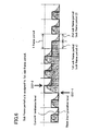
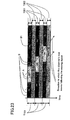
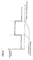
- Figure 46 shows a luminance change in accordance with time of one horizontal line in a screen when an object horizontally moves with a still background in a conventional impulse-type image display apparatus.
- the horizontal axis represents the luminance state in the horizontal direction of the screen (the position of the pixel portion in the horizontal direction), and the vertical axis represents the time.
- Figure 46 shows images displayed on the screen in three frames.
- each one-frame period T101 is a cycle by which the image is updated.
- a light-on period T102 is at the beginning of each one-frame period T101.
- a light-off period T103 follows the light-on period T102 until the image is updated in the next frame. In the light-off period T103, the luminance is minimum.
- a display portion A of the moving object is sandwiched between display portions B of the still background. Each time the image is updated frame by frame, the display portion A moves rightward.
- the observer's eye paying attention to the display portion A follows the display portion A and thus moves in the direction represented by the oblique thick arrow.
- a value obtained by time integration of a luminance change in the direction of the movement of the object is perceived as the brightness by the human eye.
- Figure 47 shows the distribution in brightness of the image shown in Figure 46 which is viewed by the observer's eye paying attention to the moving object.
- the period from an image update to the next image update is mostly a light-off period T103.
- the luminance in the light-off period T103 which is sufficiently low, does not contribute to the time-integrated luminance (value of the vertical axis).
- the observer's eye clearly views the difference in brightness at the border between the still background and the moving object. Therefore, the observer's eye can clearly distinguish the object from the background.
- hold-type image display apparatuses are inferior to the impulse-type image display apparatuses in the quality of moving images. This will be described in detail below.
- Figure 48 shows a luminance change in accordance with time of one horizontal line in a screen when an object horizontally moves with a still background in a general conventional hold-type image display apparatus.
- the horizontal axis represents the luminance state in the horizontal direction of the screen (the position of the pixel portion in the horizontal direction), and the vertical axis represents the time.
- Figure 48 shows images displayed on the screen in three frames.
- each one-frame period T101 is entirely a light-on period T102. No light-off period is provided.
- Figure 49 shows the distribution in brightness of the image shown in Figure 48 which is viewed by the observer's eye paying attention to the moving object.
- the one-frame period T101 is entirely a light-on period T102, the object is displayed as remaining at the same position from an image update until the next image update.
- the value obtained by time integration of a luminance change in the direction of the movement of the object does not reflect the difference in brightness at the border between the still background and the moving object. Therefore, the observer's eye views the border as a movement blur. This is one cause of the poor image quality of general conventional hold-type image display apparatuses.
- minimum luminance insertion system One solution to this problem of the hold-type image display apparatuses is to reduce the duration of the light-on period to about half and provide a period in which image display is performed at the minimum luminance level (minimum luminance period).
- this system will be referred to as the "minimum (luminance) insertion system”.
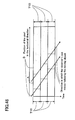
- Figure 50 shows a luminance change in accordance with time of one horizontal line in a screen when an object horizontally moves with a still background in a conventional hold-type image display apparatus which adopts the minimum (luminance) insertion system.
- the horizontal axis represents the luminance state in the horizontal direction of the screen (the position of the pixel portion in the horizontal direction), and the vertical axis represents the time.
- Figure 50 shows images displayed on the screen in three frames.
- each one-frame period T101 includes a 1/2-frame light-off period (or a minimum luminance period or a minimum (luminance) insertion period) T103.
- Figure 51 shows the distribution in brightness of the image shown in Figure 50 which is viewed by the observer's eye paying attention to the moving object.
- Figure 51 shows that the movement blur is alleviated, as compared with the general conventional hold-type image display apparatus shown in Figure 49 .
- each one-frame period includes a minimum luminance period (or a minimum (luminance) insertion period or a light-off period) even when the image display is performed at the maximum gradation level. Therefore, the maximum luminance perceived by the observer's eye is half of that in the general conventional hold-type image display apparatuses which do not adopt the minimum (luminance) insertion system.
- transmissive display devices such as transmissive liquid crystal display devices and the like.
- the luminance of the backlight is increased in order to guarantee approximately the same level of maximum luminance as that of the general conventional hold-type image display apparatuses which do not adopt the minimum (luminance) insertion system.
- This proposed solution has the following drawbacks. First, the power consumption of the backlight is raised. Second, even while the image display is performed at the minimum luminance (black period), the light from the backlight can be transmitted through the display device. Therefore, the minimum luminance level cannot be approximately the same as that of the hold-type image display apparatuses which do not adopt the minimum (luminance) insertion system. As a result, the contrast is reduced.
- Japanese Laid-Open Publication No. 2001-296841 proposes the following image display method by claims 27 through 41 in order to improve the quality of moving images by, for example, solving the problem of movement blur while guaranteeing approximately the same level of maximum luminance as that of the general conventional hold-type image display apparatuses which do not adopt the minimum (luminance) insertion system.
- a specific method for driving the display device and providing an image signal of a certain gradation level is described in example 7 of Japanese Laid-Open Publication No. 2001-296841 in detail.
- Japanese Laid-Open Publication No. 2001-296841 is entirely incorporated herein for reference.
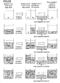
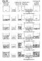
- one frame of image display is performed using two sub frame periods, i.e., the first sub frame period and the second sub frame period.
- the gradation level of an input image signal is 0% or greater and less than 50%
- an image signal of a gradation level of 0% to 100% is supplied in the first sub frame period
- an image signal of a gradation level of 0% is supplied in the second sub frame period.
- the gradation level of the input image signal is 50% or greater and less than 100%
- an image signal of a gradation level of 0% to 100% is supplied in the first sub frame period
- an image signal of a gradation level of 100% is supplied in the second sub frame period.
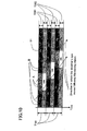
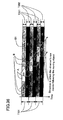
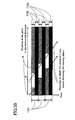
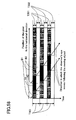
- Figure 52 shows a luminance change in accordance with time of one horizontal line in a screen when an object horizontally moves with a still background in a conventional hold-type image display apparatus disclosed by Japanese Laid-Open Publication No. 2001-296841 .
- the horizontal axis represents the luminance state in the horizontal direction of the screen (the position of the pixel portion in the horizontal direction), and the vertical axis represents the time.
- Figure 52 shows images displayed on the screen in three frames.
- each one-frame period T101 includes two sub frame periods T201 and T202.
- the display portion B is in a light-on state only in the first sub frame period T201 and is in a light-off state (0%) in the second sub frame period T202.
- the gradation level of the input image signal is sufficiently high. Therefore, the display portion A is in a light-on state at the maximum luminance (100%) in the second sub frame period T202, and is in a light-on state at the luminance of 20% with an image signal of a gradation signal of 0% to 100% in the first sub frame period T201.
- the numerals with "%" represent the luminance level of the image with respect to the maximum display ability of 100%. For example, the numeral surrounded by the dotted line for B1 represents the luminance of 40%.
- Such an image display method can guarantee approximately the same level of maximum luminance and contrast as those of the conventional hold-type image display apparatuses which do not adopt the minimum (luminance) insertion system, and also can improve the quality of moving images where the gradation level of the input image signal is sufficiently low.
- Japanese Laid-Open Publication No. 2002-23707 discloses another method for suppressing the reduction in luminance of the hold-type image display apparatuses which adopt the minimum (luminance) insertion system.
- a one-frame period includes a plurality of sub frame periods, and the luminance of one of the latter frames is attenuated at a prescribed ratio in accordance with the luminance of an input image signal. Therefore, the movement blur which is visually perceived in the general conventional hold-type image display apparatuses can be prevented.
- the conventional image display apparatus disclosed by Japanese Laid-Open Publication No. 2001-296841 can provide substantially the same effect as that of the conventional hold-type image display apparatus which adopts the minimum (luminance) insertion system shown in Figures 50 and 51 , as long as the gradation level of the input image signal is sufficiently low.
- the gradation level of the input image signal is high, the following problems occur.
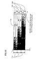
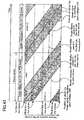
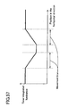
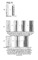
- Figure 53 shows the distribution in brightness of the image shown in Figure 52 which is viewed by the observer's eye paying attention to the moving object.
- a portion of the image is brighter than the original image and another portion of the image is darker than the original image.
- the observer's eye views abnormally bright and abnormally dark portions at the leading end or the trailing end of the moving object, which are not viewed in a still image. This lowers the quality of moving images.
- the time-wise center of gravity of the light-on period is significantly different between when the gradation level of the input image signal is less than 50% and when the gradation level of the input image signal is 50% or greater.
- the time-wise center of gravity of luminance in the light-on period is the first sub frame period T201 since an image signal of a gradation level of 0% is supplied in the second sub frame period T202.
- the time-wise center of gravity of the light-on period is the second sub frame period T202 since an image signal of a gradation level of 100% is supplied in the second sub frame period T202. For this reason, abnormally bright and abnormally dark portions are viewed at the leading end or the trailing end of the moving object, in terms of the value obtained by time integration of a luminance change in the direction of the movement of the object.
- Display panels which use the hold-type display devices such as, for example, liquid crystal display devices and EL display devices generally have substantially the same gamma luminance characteristic as that of CRTs in order to be compatible with the general image signals.
- Figure 54 is a graph illustrating the relationship between the gradation level of an input image signal and the display luminance of a display panel having such a gamma luminance characteristic. As shown in Figure 54 , the relationship is represented by a curve which is generally concaved toward lower luminance. From this, it is understood that the point of luminance of 50% and the point of gradation level of 50% do not match each other.
- Figure 55 shows the relationship between the gradation level of an input signal and the time-integrated luminance corresponding to the brightness perceived by the observer's eye, when the display control as described in example 7 of Japanese Laid-Open Publication No. 2001-296841 is performed using a hold-type image display device having the gamma luminance characteristic.
- the method disclosed by Japanese Laid-Open Publication 2002-23707 places the image into a light-on state in one of the latter sub frame periods of each one-frame period, and thus can suppress the reduction in luminance and contrast as compared with the general hold-type image display apparatus which adopt the minimum (luminance) insertion type shown in Figures 50 and 51 .
- this method does not provide a significant effect for preventing the movement blur.
- the contrast obtained by this method is lower than that of the general conventional hold-type image display apparatuses.
- an image display apparatus for performing image display by dividing one frame period into a plurality of sub-frame periods, determining a gradation level of each of the sub-frame periods in accordance with a gradation level of an input image signal and supplying the determined gradation level to an image display section.
- the image display apparatus comprises:
- the display control section when the gradation of the input image signal is relatively smallest, supplies a relatively smallest gradation level to all the sub-frame periods; and when the gradation of the input image signal is relatively largest, the display control section supplies a relatively largest gradation level to all the sub-frame periods.
- the display control section performs image display by the image display section by controlling the gradation level supplied in each sub-frame period, such that a time-integrated value of luminance corresponding to the input image signal represents a prescribed luminance characteristic.
- an image display apparatus for performing one frame of image display by a sum of time-integrated values of luminance displayed in an image display section in n sub-frame periods (where n is an integer of 2 or greater).
- the image display apparatus comprises:
- an image display apparatus for performing one frame of image display by a sum of time-integrated values of luminance displayed in an image display section in n sub-frame periods (where n is an odd number of 3 or greater).
- the image display apparatus comprises:
- an image display apparatus for performing one frame of image display by a sum of time-integrated values of luminance displayed in an image display section in n sub-frame periods (where n is an even number of 2 or greater).
- the image display apparatus comprises:
- an image display apparatus for performing one frame of image display by a sum of time-integrated values of luminance displayed in an image display section in two sub-frame periods.
- the image display apparatus comprises:
- an image display apparatus for performing one frame of image display by a sum of time-integrated values of luminance displayed in an image display section in two sub-frame periods.
- the image display apparatus comprises:
- an image display apparatus for performing one frame of image display by a sum of time-integrated values of luminance displayed in an image display section in two sub-frame periods.
- the image display apparatus comprises:
- an image display apparatus for performing one frame of image display by a sum of time-integrated values of luminance displayed in an image display section in two sub-frame periods.
- the image display apparatus comprises:
- an image display apparatus for performing one frame of image display by a sum of time-integrated values of luminance displayed in an image display section in two sub-frame periods.
- the image display apparatus comprises:
- the sub-frame periods have an identical length to each other or different lengths from each other.
- the display control section sets an upper limit of the gradation level of the image signal supplied in each sub-frame period.
- the display control section sets the upper limits so as to fulfill: L ⁇ j - i ⁇ L ⁇ j - i + 1 ; L ⁇ j + i ⁇ L ⁇ j + i + 1 where i is an integer of 0 or greater and less than j.
- the image display section sets the gradation level of the image signal supplied in each sub-frame period after being increased or decreased in accordance with the gradation level of the input image signal, such that the relationship between the gradation level of the input image signal and the time-integrated values of luminance during one frame period exhibits an appropriate gamma luminance characteristic.
- the image display apparatus further comprises a gamma luminance characteristic setting section for externally setting the gamma luminance characteristic, wherein:
- the image display apparatus further comprises a temperature detection section for detecting a temperature of a display panel or the vicinity thereof, wherein:
- the display control section sets the gradation level of the image signal supplied in each sub-frame period, such that the ratio between the luminance level displayed in each sub-frame period of a color other than a color having a highest gradation level of input image signal, is equal to the ratio between the luminance level displayed in each sub-frame period of the color having the highest gradation level of input image signal.
- the gradation level allocated to the central sub-frame period in one frame period is higher than the gradation levels allocated to the other sub-frame periods at ends of one frame period.
- the luminance level of the image signal allocated to the central sub-frame period in one frame period is higher than the luminance levels of the image signal allocated to the other sub-frame periods at ends of one frame period.
- a time-wise center of gravity of time-integrated values of luminance in the plurality of sub-frame periods moves within one sub-frame period.
- the display control section performs display control on each of a plurality of pixel portions on a display screen.
- each pixel portion includes one pixel or a prescribed number of pixels.
- the gradation level of the image signal allocated in an earlier sub-frame period is half or less of the gradation level of the image signal allocated in a later sub-frame period.
- the sub-frame periods have an identical length to each other or different lengths from each other.
- the display control section sets an upper limit of the gradation level of the image signal supplied in each sub-frame period.
- the display control section sets the upper limits so as to fulfill: L ⁇ j - i ⁇ L ⁇ j - i + 1 ; L ⁇ j + i ⁇ L ⁇ j + i + 1 where i is an integer of 0 or greater and less than j.
- the image display section sets the gradation level of the image signal supplied in each sub-frame period after being increased or decreased in accordance with the gradation level of the input image signal, such that the relationship between the gradation level of the input image signal and the time-integrated values of luminance during one frame period exhibits an appropriate gamma luminance characteristic.
- the image display apparatus further comprises a gamma luminance characteristic setting section for externally setting the gamma luminance characteristic, wherein:
- the image display apparatus further comprises a temperature detection section for detecting a temperature of a display panel or the vicinity thereof, wherein:
- the input image signal has a plurality of color components
- the display control section sets the gradation level of the image signal supplied in each sub-frame period, such that the ratio between the luminance level displayed in each sub-frame period of a color other than a color having a highest gradation level of input image signal, is equal to the ratio between the luminance level displayed in each sub-frame period of the color having the highest gradation level of input image signal.
- the gradation level which is greater than the prescribed value is a gradation level of greater than 90% where the relatively largest gradation level is 100%, and the gradation level which is lower than the prescribed value is a gradation level lower than 10% where the relatively smallest gradation level is 0%.
- the gradation level which is greater than the prescribed value is a gradation level corresponding to a luminance level greater than 90% where the relatively largest luminance level is 100%, and the gradation level which is lower than the prescribed value is a gradation level corresponding to a luminance level lower than 10% where the relatively smallest luminance level is 0%.
- the gradation level which is greater than the prescribed value is a gradation level greater than 98% where the relatively largest gradation level is 100%, and the gradation level which is lower than the prescribed value is a gradation level lower than 2% where the relatively smallest gradation level is 0%.
- the gradation level which is greater than the prescribed value is a gradation level corresponding to a luminance level greater than 98% where the relatively largest luminance level is 100%, and the gradation level which is lower than the prescribed value is a gradation level corresponding to a luminance level lower than 2% where the relatively smallest luminance level is 0%.
- the gradation level allocated to the central sub-frame period in one frame period is higher than the gradation levels allocated to the other sub-frame periods at ends of one frame period.
- the luminance level of the image signal allocated to the central sub-frame period in one frame period is higher than the luminance levels of the image signal allocated to the other sub-frame periods at ends of one frame period.
- a time-wise center of gravity of time-integrated values of luminance in the plurality of sub-frame periods moves within one sub-frame period.
- the display control section performs display control on each of a plurality of pixel portions on a display screen.
- each pixel portion includes one pixel or a prescribed number of pixels.
- the sub-frame periods have an identical length to each other or different lengths from each other.
- the m'th sub-frame period has a longer length than the other sub-frame periods.
- the display control section sets an upper limit of the gradation level of the image signal supplied in each sub-frame period.
- the display control section sets the upper limits so as to fulfill: L ⁇ j - i ⁇ L ⁇ j - i + 1 ; L ⁇ j + i ⁇ L ⁇ j + i + 1 where i is an integer of 0 or greater and less than j.
- the display control section sets the threshold level acting as a reference for the gradation level of the image signal supplied in each sub-frame period, and also sets the gradation level of the image signal supplied in each sub-frame period, such that the relationship between the gradation level of the input image signal and the time-integrated values of luminance during one frame period exhibits an appropriate gamma luminance characteristic.
- the image display apparatus further comprises a gamma luminance characteristic setting section for externally setting the gamma luminance characteristic, wherein:
- the image display apparatus further comprises a temperature detection section for detecting a temperature of a display panel or the vicinity thereof, wherein:
- the display control section sets the gradation level of the image signal supplied in each sub-frame period, such that the ratio between the luminance level displayed in each sub-frame period of a color other than a color having a highest gradation level of input image signal, is equal to the ratio between the luminance level displayed in each sub-frame period of the color having the highest gradation level of input image signal.
- the display control section includes:
- the gradation level which is greater than the prescribed value is a gradation level of greater than 90% where the relatively largest gradation level is 100%, and the gradation level which is lower than the prescribed value is a gradation level lower than 10% where the relatively smallest gradation level is 0%.
- the gradation level which is greater than the prescribed value is a gradation level corresponding to a luminance level greater than 90% where the relatively largest luminance level is 100%, and the gradation level which is lower than the prescribed value is a gradation level corresponding to a luminance level lower than 10% where the relatively smallest luminance level is 0%.
- the gradation level which is greater than the prescribed value is a gradation level greater than 98% where the relatively largest gradation level is 100%, and the gradation level which is lower than the prescribed value is a gradation level lower than 2% where the relatively smallest gradation level is 0%.
- the gradation level which is greater than the prescribed value is a gradation level corresponding to a luminance level greater than 98% where the relatively largest luminance level is 100%, and the gradation level which is lower than the prescribed value is a gradation level corresponding to a luminance level lower than 2% where the relatively smallest luminance level is 0%.
- the gradation level allocated to the central sub-frame period in one frame period is higher than the gradation levels allocated to the other sub-frame periods at ends of one frame period.
- the luminance level of the image signal allocated to the central sub-frame period in one frame period is higher than the luminance levels of the image signal allocated to the other sub-frame periods at ends of one frame period.
- a time-wise center of gravity of time-integrated values of luminance in the plurality of sub-frame periods moves within one sub-frame period.
- the display control section performs display control on each of a plurality of pixel portions on a display screen.
- each pixel portion includes one pixel or a prescribed number of pixels.
- the sub-frame periods have an identical length to each other or different lengths from each other.
- the display control section sets an upper limit of the gradation level of the image signal supplied in each sub-frame period.
- the display control section sets the upper limits so as to fulfill: L ⁇ j - i ⁇ L ⁇ j - i + 1 ; L ⁇ j + i ⁇ L ⁇ j + i + 1 where i is an integer of 0 or greater and less than j.
- the display control section sets the threshold level acting as reference for the gradation level of the image signal supplied in each sub-frame period, and also sets the gradation level of the image signal supplied in each sub-frame period, such that the relationship between the gradation level of the input image signal and the time-integrated values of luminance during one frame period exhibits an appropriate gamma luminance characteristic.
- the image display apparatus further comprises a gamma luminance characteristic setting section for externally setting the gamma luminance characteristic, wherein:
- the image display apparatus further comprises a temperature detection section for detecting a temperature of a display panel or the vicinity thereof, wherein:
- the display control section sets the gradation level of the image signal supplied in each sub-frame period, such that the ratio between the luminance level displayed in each sub-frame period of a color other than a color having a highest gradation level of input image signal, is equal to the ratio between the luminance level displayed in each sub-frame period of the color having the highest gradation level of input image signal.
- the gradation level which is greater than the prescribed value is a gradation level of greater than 90% where the relatively largest gradation level is 100%, and the gradation level which is lower than the prescribed value is a gradation level lower than 10% where the relatively smallest gradation level is 0%.
- the gradation level which is greater than the prescribed value is a gradation level corresponding to a luminance level greater than 90% where the relatively largest luminance level is 100%, and the gradation level which is lower than the prescribed value is a gradation level corresponding to a luminance level lower than 10% where the relatively smallest luminance level is 0%.
- the gradation level which is greater than the prescribed value is a gradation level greater than 98% where the relatively largest gradation level is 100%, and the gradation level which is lower than the prescribed value is a gradation level lower than 2% where the relatively smallest gradation level is 0%.
- the gradation level which is greater than the prescribed value is a gradation level corresponding to a luminance level greater than 98% where the relatively largest luminance level is 100%, and the gradation level which is lower than the prescribed value is a gradation level corresponding to a luminance level lower than 2% where the relatively smallest luminance level is 0%.
- the gradation level allocated to the central sub-frame period in one frame period is higher than the gradation levels allocated to the other sub-frame periods at ends of one frame period.
- the luminance level of the image signal allocated to the central sub-frame period in one frame period is higher than the luminance levels of the image signal allocated to the other sub-frame periods at ends of one frame period.
- a time-wise center of gravity of time-integrated values of luminance in the plurality of sub-frame periods moves within one sub-frame period.
- the display control section performs display control on each of a plurality of pixel portions on a display screen.
- each pixel portion includes one pixel or a prescribed number of pixels.
- the sub-frame periods have an identical length to each other or different lengths from each other.
- the sub-frame period ⁇ when a response time of the image display section to a decrease in the luminance level is shorter than a response time of the image display section to an increase in the luminance level, the sub-frame period ⁇ is assigned to a second sub-frame period among the two sub-frame periods; and when the response time of the image display section to the decrease in the luminance level is longer than the response time of the image display section to the increase in the luminance level, the sub-frame period ⁇ is assigned to a first sub-frame period among the two sub-frame periods.
- a relatively largest luminance level of the image display section is Lmax and a relatively smallest luminance level of the image display section is Lmin
- the sub-frame period ⁇ is assigned to a second sub-frame period among the two sub-frame periods
- the response time of the image display section to the luminance switch from the relatively largest luminance level of Lmax to the relatively smallest luminance level of Lmin is longer than the response time of the image display section to the luminance switch from the relatively smallest luminance level of Lmin to the relatively largest luminance level of Lmax
- the sub-frame period ⁇ is assigned to a first sub-frame period among the two sub-frame periods.
- the display control section sets an upper limit of the gradation level of the image signal supplied in each sub-frame period.
- the display control section sets L1 and L2 so as to fulfill the relationship of L1 ⁇ L2.
- the display control section sets the threshold level acting as reference for the gradation level of the image signal supplied in each sub-frame period, and also sets the gradation level of the image signal supplied in each sub-frame period, such that the relationship between the gradation level of the input image signal and the time-integrated values of luminance during one frame period exhibits an appropriate gamma luminance characteristic.
- the image display apparatus further comprises a gamma luminance characteristic setting section for externally setting the gamma luminance characteristic, wherein:
- the image display apparatus further comprises a temperature detection section for detecting a temperature of a display panel or the vicinity thereof, wherein:
- the display control section sets the gradation level of the image signal supplied in each sub-frame period, such that the ratio between the luminance level displayed in each sub-frame period of a color other than a color having a highest gradation level of input image signal, is equal to the ratio between the luminance level displayed in each sub-frame period of the color having the highest gradation level of input image signal.
- the display control section includes:
- the gradation level which is greater than the prescribed value is a gradation level of greater than 90% where the relatively largest gradation level is 100%, and the gradation level which is lower than the prescribed value is a gradation level lower than 10% where the relatively smallest gradation level is 0%.
- the gradation level which is greater than the prescribed value is a gradation level corresponding to a luminance level greater than 90% where the relatively largest luminance level is 100%, and the gradation level which is lower than the prescribed value is a gradation level corresponding to a luminance level lower than 10% where the relatively smallest luminance level is 0%.
- the gradation level which is greater than the prescribed value is a gradation level greater than 98% where the relatively largest gradation level is 100%, and the gradation level which is lower than the prescribed value is a gradation level lower than 2% where the relatively smallest gradation level is 0%.
- the gradation level which is greater than the prescribed value is a gradation level corresponding to a luminance level greater than 98% where the relatively largest luminance level is 100%, and the gradation level which is lower than the prescribed value is a gradation level corresponding to a luminance level lower than 2% where the relatively smallest luminance level is 0%.
- the display control section performs display control on each of a plurality of pixel portions on a display screen.
- each pixel portion includes one pixel or a prescribed number of pixels.
- the sub-frame periods have an identical length to each other or different lengths from each other.
- the gradation level of the input image signal when the gradation level of the input image signal is greater than the threshold level T1 and equal to or less than the threshold level T2, the gradation level of the image signal supplied in the sub-frame period ⁇ and the gradation level of the image signal supplied in the sub-frame period ⁇ are set, such that the difference between the gradation levels is constant, or such that the difference between the luminance level in the sub-frame period ⁇ and the luminance level in the sub-frame period ⁇ is constant.
- the gradation level of the image signal allocated in an earlier sub-frame period is half or less of the gradation level of the image signal allocated in a later sub-frame period.
- the gradation level of the input image signal when the gradation level of the input image signal is greater than the threshold level T1 and equal to or less than the threshold level T2, the gradation level of the image signal supplied in the sub-frame period ⁇ and the gradation level of the image signal supplied in the sub-frame period ⁇ are set, such that the relationship between the gradation levels is set by a function, or such that the relationship between the luminance level in the sub-frame period ⁇ and the luminance level in the sub-frame period ⁇ is set by a function.
- the sub-frame period ⁇ when a response time of the image display section to a decrease in the luminance level is shorter than a response time of the image display section to an increase in the luminance level, the sub-frame period ⁇ is assigned to a second sub-frame period among the two sub-frame periods; and when the response time of the image display section to the decrease in the luminance level is longer than the response time of the image display section to the increase in the luminance level, the sub-frame period ⁇ is assigned to a first sub-frame period among the two sub-frame periods.
- a relatively largest luminance level of the image display section is Lmax and a relatively smallest luminance level of the image display section is Lmin
- the sub-frame period ⁇ is assigned to a second sub-frame period among the two sub-frame periods
- the response time of the image display section to the luminance switch from the relatively largest luminance level of Lmax to the relatively smallest luminance level of Lmin is longer than the response time of the image display section to the luminance switch from the relatively smallest luminance level of Lmin to the relatively largest luminance level of Lmax
- the sub-frame period ⁇ is assigned to a first sub-frame period among the two sub-frame periods.
- the display control section sets an upper limit of the gradation level of the image signal supplied in each sub-frame period.
- the display control section sets L1 and L2 so as to fulfill the relationship of L1 ⁇ L2.
- the display control section sets the threshold level acting as a reference for the gradation level of the image signal supplied in each sub-frame period, and also sets the gradation level of the image signal supplied in each sub-frame period, such that the relationship between the gradation level of the input image signal and the time-integrated values of luminance during one frame period exhibits an appropriate gamma luminance characteristic.
- the image display apparatus further comprises a gamma luminance characteristic setting section for externally setting the gamma luminance characteristic, wherein:
- the image display apparatus further comprises a temperature detection section for detecting a temperature of a display panel or the vicinity thereof, wherein:
- the display control section sets the gradation level of the image signal supplied in each sub-frame period, such that the ratio between the luminance level displayed in each sub-frame period of a color other than a color having a highest gradation level of input image signal, is equal to the ratio between the luminance level displayed in each sub-frame period of the color having the highest gradation level of input image signal.
- the display control section includes:
- the display control section performs display control on each of a plurality of pixel portions on a display screen.
- the gradation level which is greater than the prescribed value is a gradation level of greater than 90% where the relatively largest gradation level is 100%, and the gradation level which is lower than the prescribed value is a gradation level lower than 10% where the relatively smallest gradation level is 0%.
- the display control section performs display control on each of a plurality of pixel portions on a display screen.
- the gradation level which is greater than the prescribed value is a gradation level corresponding to a luminance level greater than 90% where the relatively largest luminance level is 100%, and the gradation level which is lower than the prescribed value is a gradation level corresponding to a luminance level lower than 10% where the relatively smallest luminance level is 0%.
- the gradation level which is greater than the prescribed value is a gradation level greater than 98% where the relatively largest gradation level is 100%, and the gradation level which is lower than the prescribed value is a gradation level lower than 2% where the relatively smallest gradation level is 0%.
- the gradation level which is greater than the prescribed value is a gradation level corresponding to a luminance level greater than 98% where the relatively largest luminance level is 100%, and the gradation level which is lower than the prescribed value is a gradation level corresponding to a luminance level lower than 2% where the relatively smallest luminance level is 0%.
- the display control section performs display control on each of a plurality of pixel portions on a display screen.
- each pixel portion includes one pixel or a prescribed number of pixels.
- the sub-frame periods have an identical length to each other or different lengths from each other.
- the gradation level of the input image signal when the gradation level of the input image signal is greater than the threshold level T1 and equal to or less than the threshold level T2, the gradation level of the image signal supplied in the sub-frame period ⁇ and the gradation level of the image signal supplied in the sub-frame period ⁇ are set, such that the difference between the gradation levels is constant, or such that the difference between the luminance level in the sub-frame period ⁇ and the luminance level in the sub-frame period ⁇ is constant.
- the gradation level of the image signal allocated in an earlier sub-frame period is half or less of the gradation level of the image signal allocated in a later sub-frame period.
- the gradation level of the input image signal when the gradation level of the input image signal is greater than the threshold level T1 and equal to or less than the threshold level T2, the gradation level of the image signal supplied in the sub-frame period ⁇ and the gradation level of the image signal supplied in the sub-frame period ⁇ are set, such that the relationship between the gradation levels is set by a function, or such that the relationship between the luminance level in the sub-frame period ⁇ and the luminance level in the sub-frame period ⁇ is set by a function.
- the sub-frame period ⁇ when a response time of the image display section to a decrease in the luminance level is shorter than a response time of the image display section to an increase in the luminance level, the sub-frame period ⁇ is assigned to a second sub-frame period among the two sub-frame periods; and when the response time of the image display section to the decrease in the luminance level is longer than the response time of the image display section to the increase in the luminance level, the sub-frame period ⁇ is assigned to a first sub-frame period among the two sub-frame periods.
- the sub-frame period ⁇ is assigned to a second sub-frame period among the two sub-frame periods; and when the response time of the image display section to the luminance switch from the relatively largest luminance level of Lmax to the relatively smallest luminance level of Lmin is longer than the response time of the image display section to the luminance switch from the relatively smallest luminance level of Lmin to the relatively largest luminance level of Lmax, the sub-frame period ⁇ is assigned to a first sub-frame period among the two sub-frame periods.
- the display control section sets an upper limit of the gradation level of the image signal supplied in each sub-frame period.
- the display control section sets L1 and L2 so as to fulfill the relationship of L1 ⁇ L2.
- the display control section sets the threshold level acting as reference for the gradation level of the image signal supplied in each sub-frame period, and also sets the gradation level of the image signal supplied in each sub-frame period, such that the relationship between the gradation level of the input image signal and the time-integrated values of luminance during one frame period exhibits an appropriate gamma luminance characteristic.
- the image display apparatus further comprises a gamma luminance characteristic setting section for externally setting the gamma luminance characteristic, wherein:
- the image display apparatus further comprises a temperature detection section for detecting a temperature of a display panel or the vicinity thereof, wherein:
- the display control section sets the gradation level of the image signal supplied in each sub-frame period, such that the ratio between the luminance level displayed in each sub-frame period of a color other than a color having a highest gradation level of the input image signal, is equal to the ratio between the luminance level displayed in each sub-frame period of the color having the highest gradation level of the input image signal.
- the display control section includes:
- the gradation level which is greater than the prescribed value is a gradation level of greater than 90% where the relatively largest gradation level is 100%, and the gradation level which is lower than the prescribed value is a gradation level lower than 10% where the relatively smallest gradation level is 0%.
- the gradation level which is greater than the prescribed value is a gradation level corresponding to a luminance level greater than 90% where the relatively largest luminance level is 100%, and the gradation level which is lower than the prescribed value is a gradation level corresponding to a luminance level lower than 10% where the relatively smallest luminance level is 0%.
- the gradation level which is greater than the prescribed value is a gradation level greater than 98% where the relatively largest gradation level is 100%, and the gradation level which is lower than the prescribed value is a gradation level lower than 2% where the relatively smallest gradation level is 0%.
- the gradation level which is greater than the prescribed value is a gradation level corresponding to a luminance level greater than 98% where the relatively largest luminance level is 100%, and the gradation level which is lower than the prescribed value is a gradation level corresponding to a luminance level lower than 2% where the relatively smallest luminance level is 0%.
- the display control section performs display control on each of a plurality of pixel portions on a display screen.
- each pixel portion includes one pixel or a prescribed number of pixels.
- the sub-frame periods have an identical length to each other or different lengths from each other.
- the sub-frame period ⁇ when a response time of the image display section to a decrease in the luminance level is shorter than a response time of the image display section to an increase in the luminance level, the sub-frame period ⁇ is assigned to a second sub-frame period among the two sub-frame periods; and when the response time of the image display section to the decrease in the luminance level is longer than the response time of the image display section to the increase in the luminance level, the sub-frame period ⁇ is assigned to a first sub-frame period among the two sub-frame periods.
- the sub-frame period ⁇ is assigned to a second sub-frame period among the two sub-frame periods; and when the response time of the image display section to the luminance switch from the relatively largest luminance level of Lmax to the relatively smallest luminance level of Lmin is longer than the response time of the image display section to the luminance switch from the relatively smallest luminance level of Lmin to the relatively largest luminance level of Lmax, the sub-frame period ⁇ is assigned to a first sub-frame period among the two sub-frame periods.
- the display control section sets an upper limit of the gradation level of the image signal supplied in each sub-frame period.
- the display control section sets L1 and L2 so as to fulfill the relationship of L1 ⁇ L2.
- the display control section sets the threshold level acting as reference for the gradation level of the image signal supplied in each sub-frame period, and also sets the gradation level of the image signal supplied in each sub-frame period, such that the relationship between the gradation level of the input image signal and the time-integrated values of luminance during one frame period exhibit an appropriate gamma luminance characteristic.
- the image display apparatus further comprises a gamma luminance characteristic setting section for externally setting the gamma luminance characteristic, wherein:
- the image display apparatus further comprises a temperature detection section for detecting a temperature of a display panel or the vicinity thereof, wherein:
- the display control section sets the gradation level of the image signal supplied in each sub-frame period, such that the ratio between the luminance level displayed in each sub-frame period of a color other than a color having a highest gradation level of input image signal, is equal to the ratio between the luminance level displayed in each sub-frame period of the color having the highest gradation level of input image signal.
- the display control section includes:
- the display control section includes:
- the gradation level which is greater than the prescribed value is a gradation level of greater than 90% where the relatively largest gradation level is 100%, and the gradation level which is lower than the prescribed value is a gradation level lower than 10% where the relatively smallest gradation level is 0%.
- the gradation level which is greater than the prescribed value is a gradation level corresponding to a luminance level greater than 90% where the relatively largest luminance level is 100%, and the gradation level which is lower than the prescribed value is a gradation level corresponding to a luminance level lower than 10% where the relatively smallest luminance level is 0%.
- the gradation level which is greater than the prescribed value is a gradation level greater than 98% where the relatively largest gradation level is 100%, and the gradation level which is lower than the prescribed value is a gradation level lower than 2% where the relatively smallest gradation level is 0%.
- the gradation level which is greater than the prescribed value is a gradation level corresponding to a luminance level greater than 98% where the relatively largest luminance level is 100%, and the gradation level which is lower than the prescribed value is a gradation level corresponding to a luminance level lower than 2% where the relatively smallest luminance level is 0%.
- the display control section performs display control on each of a plurality of pixel portions on a display screen.
- each pixel portion includes one pixel or a prescribed number of pixels.
- the sub-frame periods have an identical length to each other or different lengths from each other.
- the sub-frame period ⁇ when a response time of the image display section to a decrease in the luminance level is shorter than a response time of the image display section to an increase in the luminance level, the sub-frame period ⁇ is assigned to a second sub-frame period among the two sub-frame periods; and when the response time of the image display section to the decrease in the luminance level is longer than the response time of the image display section to the increase in the luminance level, the sub-frame period ⁇ is assigned to a first sub-frame period among the two sub-frame periods.
- the sub-frame period ⁇ is assigned to a second sub-frame period among the two sub-frame periods; and when the response time of the image display section to the luminance switch from the relatively largest luminance level of Lmax to the relatively smallest luminance level of Lmin is longer than the response time of the image display section to the luminance switch from the relatively smallest luminance level of Lmin to the relatively largest luminance level of Lmax, the sub-frame period ⁇ is assigned to a first sub-frame period among the two sub-frame periods.
- the display control section sets an upper limit of the gradation level of the image signal supplied in each sub-frame period.
- the display control section sets L1 and L2 so as to fulfill the relationship of L1 ⁇ L2.
- the display control section sets the threshold level acting as reference for the gradation level of the image signal supplied in each sub-frame period, and also sets the gradation level of the image signal supplied in each sub-frame period, such that the relationship between the gradation level of the input image signal and the time-integrated values of luminance during one frame period exhibits an appropriate gamma luminance characteristic.
- the image display apparatus further comprises a gamma luminance characteristic setting section for externally setting the gamma luminance characteristic, wherein:
- the image display apparatus further comprises a temperature detection section for detecting a temperature of a display panel or the vicinity thereof, wherein:
- the display control section sets the gradation level of the image signal supplied in each sub-frame period, such that the ratio between the luminance level displayed in each sub-frame period of a color other than a color having a highest gradation level of the input image signal, is equal to the ratio between the luminance level displayed in each sub-frame period of the color having the highest gradation level of the input image signal.
- the display control section includes:
- the display control section includes:
- the gradation level which is greater than the prescribed value is a gradation level of greater than 90% where the relatively largest gradation level is 100%, and the gradation level which is lower than the prescribed value is a gradation level lower than 10% where the relatively smallest gradation level is 0%.
- the gradation level which is greater than the prescribed value is a gradation level corresponding to a luminance level greater than 90% where the relatively largest luminance level is 100%, and the gradation level which is lower than the prescribed value is a gradation level corresponding to a luminance level lower than 10% where the relatively smallest luminance level is 0%.
- the gradation level which is greater than the prescribed value is a gradation level greater than 98% where the relatively largest gradation level is 100%, and the gradation level which is lower than the prescribed value is a gradation level lower than 2% where the relatively smallest gradation level is 0%.
- the gradation level which is greater than the prescribed value is a gradation level corresponding to a luminance level greater than 98% where the relatively largest luminance level is 100%, and the gradation level which is lower than the prescribed value is a gradation level corresponding to a luminance level lower than 2% where the relatively smallest luminance level is 0%.
- the display control section performs display control on each of a plurality of pixel portions on a display screen.
- each pixel portion includes one pixel or a prescribed number of pixels.
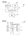
- an electronic apparatus for performing image display on a display screen of an image display section of an image display apparatus according to the first aspect of the present invention.
- a liquid crystal TV comprising:
- a liquid crystal monitoring apparatus comprising:
- an image display method for performing one frame of image display by a sum of time-integrated values of luminance displayed in an image display section in n sub-frame periods , where n is an integer of 2 or greater.
- the method comprises the following steps:
- an image display method for performing one frame of image display by a sum of time-integrated values of luminance displayed in an image display section in n sub-frame periods, wherein:
- an image display method for performing one frame of image display by a sum of time-integrated values of luminance displayed in an image display section in n sub-frame periods, wherein:
- an image display method for performing one frame of image display by a sum of time-integrated values of luminance displayed in an image display section in two sub-frame periods, wherein one of the sub-frame periods is referred to as a sub-frame period ⁇ , and the other sub-frame period is referred to as a sub-frame period ⁇ ; the method comprising the following steps:
- an image display method for performing one frame of image display by a sum of time-integrated values of luminance displayed in an image display section in two sub-frame periods, wherein one of the sub-frame periods is referred to as a sub-frame period ⁇ , and the other sub-frame period is referred to as a sub-frame period ⁇ ; and threshold levels, T1 and T2, of the gradation levels in the two sub-frame periods are defined, and the threshold level T2 is greater than the threshold level T1; the method comprising the following steps:
- an image display method for performing one frame of image display by a sum of time-integrated values of luminance displayed in an image display section in two sub-frame periods, wherein one of the sub-frame periods is referred to as a sub-frame period ⁇ , and the other sub-frame period is referred to as a sub-frame period ⁇ ; threshold levels, T1 and T2, of the gradation levels in the two sub-frame periods are defined, and the threshold level T2 is greater than the threshold level T1; and a gradation level L is uniquely determined; the method comprising the following steps:
- an image display method for performing one frame of image display by a sum of time-integrated values of luminance displayed in an image display section in two sub-frame periods, wherein one of the sub-frame periods is referred to as a sub-frame period ⁇ , and the other sub-frame period is referred to as a sub-frame period ⁇ ; the method comprising the following steps:
- an image display method for performing one frame of image display by a sum of time-integrated values of luminance displayed in an image display section in two sub-frame periods, wherein one of the sub-frame periods is referred to as a sub-frame period ⁇ , and the other sub-frame period is referred to as a sub-frame period ⁇ ; the method comprising the following steps:
- a computer program for allowing a computer to execute an image display method according to the thirteenth aspect of the present invention.
- a computer-readable recording medium having a computer program according to the twenty first aspect of the present invention stored thereon.
- a method of supplying, for display, an image of an input image signal including at least a moving object portion and a background portion, wherein a frame period is divided into a plurality of sub-frame periods including at least an ⁇ sub-frame period and a ⁇ sub-frame period, comprising:
- the plurality of sub-frame periods is two sub-frame periods.
- a method of displaying including the method of the twenty third, further comprising:
- a method of displaying including the method of the first embodiment of the twenty third aspect of the present invention, further comprising:
- the ⁇ sub-frame period is assigned to a second sub-frame period of the two sub-frame periods; and when the response time of the image display section to the decrease in the luminance level is longer than the response time of the image display section to the increase in the luminance level, the sub-frame period ⁇ is assigned to a first sub-frame period of the two sub-frame periods.
- a device for performing the method of the twenty fifth aspect of the present invention wherein a response time of the image display section to a decrease in the luminance level is relatively shorter than a response time of the image display section to an increase in the luminance level, and the ⁇ sub-frame period is assigned to a second sub-frame period of the two sub-frame periods.
- a device for performing the method of the twenty fifth aspect of the present invention wherein a response of the image display section to the decrease in the luminance level is longer than the response time of the image display section to the increase in the luminance level, and the sub-frame period ⁇ is assigned to a first sub-frame period of the two sub-frame periods.
- a computer program for allowing a computer to execute a method according to the twenty third aspect of the present invention is provided.
- a computer program for allowing a computer to execute a method according to the first embodiment of the twenty third aspect of the present invention is a computer program for allowing a computer to execute a method according to the first embodiment of the twenty third aspect of the present invention.
- a computer program for allowing a computer to execute a method according to the twenty fourth aspect of the present invention is provided.
- a computer program for allowing a computer to execute a method according to the twenty fifth aspect of the present invention is provided.
- a computer program for allowing a computer to execute a method according to the embodiment of the twenty second of the present invention is provided.
- a computer-readable recording medium having a computer program according to the twenty eighth aspect of the present invention.
- a computer-readable recording medium having a computer program according to the twenty ninth aspect of the present invention.
- a computer-readable recording medium having a computer program according to the thirtieth aspect of the present invention.
- a computer-readable recording medium having a computer program according to the thirty third aspect of the present invention.
- a computer-readable recording medium having a computer program according to the thirty second aspect of the present invention.
- the plurality of sub-frame periods is two sub-frame periods.
- a method of displaying including the method of the thirty eighth aspect of the present invention further comprises:
- a method of displaying including the method of the embodiment of the thirty eighth aspect of the present invention, further comprises:
- a computer program for allowing a computer to execute a method according to the thirty eighth aspect of the present invention is provided.
- a computer program for allowing a computer to execute a method according to the embodiment of the thirty eighth aspect of the present invention is provided.
- a computer program for allowing a computer to execute a method according to the thirty ninth aspect of the present invention is provided.
- a computer program for allowing a computer to execute a method according to the forty aspect of the present invention is provided.
- a computer program for allowing a computer to execute a method according to the forty first aspect of the present invention is provided.
- a computer program for allowing a computer to execute a method according to the forty second aspect of the present invention is provided.
- a computer program for allowing a computer to execute a method according to the forty third aspect of the present invention is provided.
- a computer program for allowing a computer to execute a method according to the forty fourth aspect of the present invention is provided.
- an apparatus for displaying an image of an input image signal including at least a moving object portion and a background portion, wherein a frame period is divided into a plurality of sub-frame periods including at least an ⁇ sub-frame period and a ⁇ sub-frame period, comprising:
- the plurality of sub-frame periods is two sub-frame periods.
- the ⁇ sub-frame period is assigned to a second sub-frame period of the two sub-frame periods; and when the response time of the means for displaying to the decrease in the luminance level is longer than the response time of the means for displaying to the increase in the luminance level, the sub-frame period ⁇ is assigned to a first sub-frame period of the two sub-frame periods.
- a response time of the means for displaying to a decrease in the luminance level is relatively shorter than a response time of the means for displaying to an increase in the luminance level, and the ⁇ sub-frame period is assigned to a second sub-frame period of the two sub-frame periods.
- a response of the means for displaying to the decrease in the luminance level is longer than the response time of the means for displaying to the increase in the luminance level, and the sub-frame period ⁇ is assigned to a first sub-frame period of the two sub-frame periods.
- an apparatus for displaying an image of an input image signal including at least a moving object portion and a background portion, wherein a frame period is divided into a plurality of sub-frame periods, comprising:
- the plurality of sub-frame periods is two sub-frame periods.
- an apparatus for displaying an image of an input image signal including at least a moving object portion and a background portion, wherein a frame period is divided into a plurality of sub-frame periods including at least an ⁇ sub-frame period and a ⁇ sub-frame period, comprising:
- the plurality of sub-frame periods is two sub-frame periods.
- the ⁇ sub-frame period is assigned to a second sub-frame period of the two sub-frame periods; and when the response time of the image display section to the decrease in the luminance level is longer than the response time of the image display section to the increase in the luminance level, the sub-frame period ⁇ is assigned to a first sub-frame period of the two sub-frame periods.
- a response time of the image display section to a decrease in the luminance level is relatively shorter than a response time of the image display section to an increase in the luminance level, and the ⁇ sub-frame period is assigned to a second sub-frame period of the two sub-frame periods.
- a response of the image display section to the decrease in the luminance level is longer than the response time of the image display section to the increase in the luminance level, and the sub-frame period ⁇ is assigned to a first sub-frame period of the two sub-frame periods.
- an apparatus for displaying an image of an input image signal including at least a moving object portion and a background portion, wherein a frame period is divided into a plurality of sub-frame periods, comprising:
- the plurality of sub-frame periods is two sub-frame periods.
- a method of supplying, for display, an image of an input image signal, wherein a frame period is divided into a plurality of sub-frames comprising:
- a luminance level of a relatively largest luminance value is supplied to at least one relatively central sub-frame.
- a luminance level of a relatively smallest value is supplied in sub-frames relatively furthest from the relatively central of the plurality of sub-frames.
- a luminance level of a relatively smallest value is supplied in sub-frames relatively furthest from the relatively central of the plurality of sub-frames.
- a relatively largest luminance value is supplied in at least one central sub-frame, and when the plurality of sub-frames is even in number, a relatively largest luminance value is supplied in at least two relatively central sub-frames.
- a method of displaying including the method of the fifty third aspect of the present invention further comprises:
- a computer program for allowing a computer to execute a method according to the fifty third aspect of the present invention is provided.
- a computer program for allowing a computer to execute a method according to the first embodiment of the fifty third aspect of the present invention is provided.
- a computer program for allowing a computer to execute a method according to the second embodiment of the fifty third aspect of the present invention is provided.
- a computer program for allowing a computer to execute a method according to the third embodiment of the fifty third aspect of the present invention is provided.
- a computer program for allowing a computer to execute a method according to the fourth embodiment of the fifty third aspect of the present invention is a computer program for allowing a computer to execute a method according to the fourth embodiment of the fifty third aspect of the present invention.
- a computer program for allowing a computer to execute a method according to the fifty fourth aspect of the present invention is provided.
- a computer program for allowing a computer to execute a method according to the fifty fifth aspect of the present invention is provided.
- a computer program for allowing a computer to execute a method according to the fifty sixth aspect of the present invention is provided.
- a computer program for allowing a computer to execute a method according to the fifty seventh aspect of the present invention is provided.
- a computer program for allowing a computer to execute a method according to the fifty eighth aspect of the present invention is provided.
- a computer program for allowing a computer to execute a method according to the fifty ninth aspect of the present invention is provided.
- a computer program for allowing a computer to execute a method according to the sixty aspect of the present invention is provided.
- a method of supplying, for display, an image of an input image signal, wherein a frame period is divided into a plurality of sub-frames comprising:
- a luminance level of a relatively largest luminance value is supplied to at least one relatively central of the plurality of sub-frames.
- a luminance level of a relatively smallest value is supplied in sub-frames relatively furthest from the relatively central of the plurality of sub-frames.
- a luminance level of a relatively smallest value is supplied in sub-frames relatively furthest from the relatively central of the plurality of sub-frames.
- a relatively largest luminance value is supplied in at least one central sub-frame, and when the plurality of sub-frames is even in number, a relatively largest luminance value is supplied in at least two relatively central sub-frames.
- a method of displaying including the method of the sixty seventh aspect of the present invention, further comprising:
- a computer program for allowing a computer to execute a method according to the sixty seventh aspect of the present invention is provided.
- a computer program for allowing a computer to execute a method according to the first embodiment of the sixty seventh aspect of the present invention is provided.
- a computer program for allowing a computer to execute a method according to the second embodiment of the sixty seventh aspect of the present invention is provided.
- a computer program for allowing a computer to execute a method according to the third embodiment of the sixty seventh aspect of the present invention is provided.
- a computer program for allowing a computer to execute a method according to the fourth embodiment of the sixty seventh aspect of the present invention is provided.
- a computer program for allowing a computer to execute a method according to the sixty eighth aspect of the present invention is provided.
- a computer program for allowing a computer to execute a method according to the sixty ninth aspect of the present invention is provided.
- a computer program for allowing a computer to execute a method according to the seventieth aspect of the present invention is provided.
- a computer program for allowing a computer to execute a method according to the seventy first aspect of the present invention is provided.
- a computer program for allowing a computer to execute a method according to the seventy second aspect of the present invention is provided.
- a computer program for allowing a computer to execute a method according to the seventy third aspect of the present invention is provided.
- a computer program for allowing a computer to execute a method according to the seventy fourth aspect of the present invention is provided.
- an apparatus for displaying an image of an input image signal, wherein a frame period is divided into a plurality of sub-frames, comprising:
- a luminance level of a relatively largest luminance value is supplied to at least one relatively central sub-frame.
- a luminance level of a relatively smallest value is supplied in sub-frames relatively furthest from the relatively central of the plurality of sub-frames.
- a luminance level of a relatively smallest value is supplied in sub-frames relatively furthest from the relatively central of the plurality of sub-frames.
- a relatively largest luminance value is supplied in at least one central sub-frame, and when the plurality of sub-frames is even in number, a relatively largest luminance value is supplied in at least two relatively central sub-frames.
- an apparatus for displaying an image of an input image signal, wherein a frame period is divided into a plurality of sub-frames, comprising:
- a luminance level of a relatively largest luminance value is supplied to at least one relatively central of the plurality of sub-frames.
- a luminance level of a relatively smallest value is supplied in sub-frames relatively furthest from the relatively central of the plurality of sub-frames.
- a luminance level of a relatively smallest value is supplied in sub-frames relatively furthest from the relatively central of the plurality of sub-frames.
- a relatively largest luminance value is supplied in at least one central sub-frame, and when the plurality of sub-frames is even in number, a relatively largest luminance value is supplied in at least two relatively central sub-frames.
- an apparatus for displaying an image of an input image signal, wherein a frame period is divided into a plurality of sub-frame periods, comprising:
- a luminance level of a relatively largest luminance value is supplied to at least one relatively central of the plurality of sub-frames.
- a luminance level of a relatively smallest value is supplied in sub-frames relatively furthest from the relatively central of the plurality of sub-frames.
- a luminance level of a relatively smallest value is supplied in sub-frames relatively furthest from the relatively central of the plurality of sub-frames.
- a relatively largest luminance value is supplied in at least one central sub-frame, and when the plurality of sub-frames is even in number, a relatively largest luminance value is supplied in at least two relatively central sub-frames.
- a computer program for allowing a computer to execute an image display method according to the fourteenth aspect of the present invention.
- a computer-readable recording medium having a computer program according to the eighty fifth aspect of the present invention stored thereon.
- a computer program for allowing a computer to execute an image display method according to the fifteenth aspect of the present invention is provided.
- a computer-readable recording medium having a computer program according to the eighty seventh aspect of the present invention stored thereon.
- a computer program for allowing a computer to execute an image display method according to the sixteenth aspect of the present invention is provided.
- a computer-readable recording medium having a computer program according to the eighty ninth aspect of the present invention stored thereon.
- a computer program for allowing a computer to execute an image display method according to the seventeenth aspect of the present invention is provided.
- a computer-readable recording medium having a computer program according to the ninety first aspect of the present invention stored thereon.
- a computer program for allowing a computer to execute an image display method according to the eighteenth aspect of the present invention is provided.
- a computer-readable recording medium having a computer program according to the ninety third aspect of the present invention stored thereon.
- a computer program for allowing a computer to execute an image display method according to the nineteenth aspect of the present invention is provided.
- a computer-readable recording medium having a computer program according to the ninety fifth aspect of the present invention stored thereon.
- a computer program for allowing a computer to execute an image display method according to the twentieth aspect of the present invention is provided.
- a computer-readable recording medium having a computer program according to the ninety seventh aspect of the present invention stored thereon.
- an electronic apparatus for performing image display on a display screen of an image display section of an image display apparatus according to the first aspect of the present invention.
- a liquid crystal TV comprising:
- a liquid crystal monitoring apparatus comprising:
- an electronic apparatus for performing image display on a display screen of an image display section of an image display apparatus according to the second aspect of the present invention.
- a liquid crystal TV comprising:
- a liquid crystal monitoring apparatus comprising:
- an electronic apparatus for performing image display on a display screen of an image display section of an image display apparatus according to the third aspect of the present invention.
- a liquid crystal TV comprising:
- a liquid crystal monitoring apparatus comprising:
- an electronic apparatus for performing image display on a display screen of an image display section of an image display apparatus according to the fourth aspect of the present invention.
- a liquid crystal TV comprising:
- a liquid crystal monitoring apparatus comprising:
- an electronic apparatus for performing image display on a display screen of an image display section of an image display apparatus according to the fifth aspect of the present invention.
- a liquid crystal TV comprising:
- a liquid crystal monitoring apparatus comprising:
- an electronic apparatus for performing image display on a display screen of an image display section of an image display apparatus according to the sixth aspect of the present invention.
- a liquid crystal TV comprising:
- a liquid crystal monitoring apparatus comprising:
- an electronic apparatus for performing image display on a display screen of an image display section of an image display apparatus according to the seventh aspect of the present invention.
- a liquid crystal TV comprising:
- a liquid crystal monitoring apparatus comprising:
- an electronic apparatus for performing image display on a display screen of an image display section of an image display apparatus according to the eighth aspect of the present invention.
- a liquid crystal TV comprising:
- a liquid crystal monitoring apparatus comprising:
- an electronic apparatus for performing image display on a display screen of an image display section of an image display apparatus according to the ninth aspect of the present invention.
- a liquid crystal TV comprising:
- a liquid crystal monitoring apparatus comprising:
- an electronic apparatus for performing image display on a display screen of an image display section of an apparatus for displaying according to the fifty first aspect of the present invention According to a hundred twenty sixth aspect of the present invention, an electronic apparatus for performing image display on a display screen of an image display section of an apparatus for displaying according to the fifty first aspect of the present invention.
- a liquid crystal TV comprising:
- a liquid crystal monitoring apparatus comprising:
- an electronic apparatus for performing image display on a display screen of an image display section of an apparatus for displaying according to the fifty second aspect of the present invention is provided.
- a liquid crystal TV comprising:
- a liquid crystal monitoring apparatus comprising:
- an electronic apparatus for performing image display on a display screen of an image display section of an apparatus for displaying according to the eighty second aspect of the present invention According to a hundred thirty second aspect of the present invention, an electronic apparatus for performing image display on a display screen of an image display section of an apparatus for displaying according to the eighty second aspect of the present invention.
- a liquid crystal TV comprising:
- a liquid crystal monitoring apparatus comprising:
- an electronic apparatus for performing image display on a display screen of an image display section of an apparatus for displaying according to the eight fourth aspect of the present invention is provided.
- a liquid crystal TV comprising:
- a liquid crystal monitoring apparatus comprising:
- an electronic apparatus for performing image display on a display screen of the means for displaying of an apparatus for displaying according to the forty ninth aspect of the present invention is provided.
- a liquid crystal TV comprising:
- a liquid crystal monitoring apparatus comprising:
- an electronic apparatus for performing image display on a display screen of the means for displaying of an apparatus for displaying according to the fiftieth aspect of the present invention is provided.
- a liquid crystal TV comprising:
- a liquid crystal monitoring apparatus comprising:
- an electronic apparatus for performing image display on a display screen of the means for displaying of an apparatus for displaying according to the eighty first aspect of the present invention is provided.
- a liquid crystal TV comprising:
- a liquid crystal monitoring apparatus comprising:
- an electronic apparatus for performing image display on a display screen of the means for displaying of an apparatus for displaying according to the eighty third aspect of the present invention is provided.
- a luminance level of the moving object supplied in a first sub-frame period is of a luminance level relatively smaller than the luminance level supplied in a second sub-frame period
- a luminance level of the background supplied in the first sub-frame period is also of a luminance level relatively smaller than the luminance level supplied in the second sub-frame period
- a luminance level of the moving object supplied in a first sub-frame period is of a luminance level relatively larger than the luminance level supplied in a second sub-frame period
- a luminance level of the background supplied in the first sub-frame period is also of a luminance level relatively larger than the luminance level supplied in the second sub-frame period.
- the gradation level of each sub frame period is controlled such that: the time-wise center of gravity of the display luminance does not move in accordance with the gradation level of the input image signal, while the reduction in the maximum luminance or contrast is suppressed.
- the quality of moving images is prevented from being lowered due to the movement blur.
- the maximum or a sufficiently high gradation level (a gradation level greater than a prescribed value) is supplied in the sub frame period which is at the time-wise center, or closest to the time-wise center, of one frame period, in the range in which the gradation level of the input image signal does not exceed the corresponding luminance level.
- the minimum or a sufficiently low gradation level (a gradation level lower than the prescribed value) is supplied to the remaining sub frame periods.
- a gradation level which is increased or decreased in accordance with the gradation level of the input image signal is supplied in the sub frame periods before and after the central sub frame period.
- the minimum or a sufficiently low gradation level (a gradation level lower than a prescribed value) is supplied in the remaining sub frame periods .
- the gradation level to be supplied to each sub frame period is determined by whether the gradation level of the input image signal is higher than the threshold level T.
- a gradation level which is increased or decreased in accordance with the gradation level of the input image signal is supplied in the sub frame periods before and after the central sub frame periods.
- the minimum or a sufficiently low gradation level (a gradation level lower than a prescribed value) is supplied in the remaining sub frame periods.
- the gradation level to be supplied to each sub frame period is determined by whether the gradation level of the input image signal is higher than the threshold level T.
- the time-wise center of gravity of the display luminance is fixed to the sub frame period which is at the time-wise center, or closest to the time-wise center, of one frame period. Therefore, the problem with the technology of, for example, Japanese Laid-Open Publication No. 2001-296841 , i.e., the problem that a change in the time-wise center of gravity of the display luminance in accordance with the gradation of the input image signal causes the abnormal luminance or the color imbalance, which lowers the image quality, is suppressed. Since the display luminance in one frame period appropriately changes, the deterioration in the quality of moving images due to the movement blur, which is caused in general conventional hold-type image display apparatuses, can be alleviated. Even when the display is performed at the maximum gradation level, the reduction in the maximum luminance and contrast, which occurs with the minimum (luminance) insertion system (with which each one-frame period includes a minimum luminance period), can be suppressed.
- n 2
- the maximum or a sufficiently high gradation level, or a gradation level which is increased or decreased by the gradation level of the input image signal is supplied in the sub frame period ⁇ .
- the gradation level to be supplied in sub frame period is determined by whether the gradation level of the input image signal is higher than the threshold level.
- the movement of the time-wise center of gravity of luminance can be minimized. Therefore, the problem with the technology of, for example, Japanese Laid-Open Publication No. 2001-296841 , i.e., the problem that a change in the time-wise center of gravity of the display luminance in accordance with the gradation of the input image signal causes the abnormal luminance or the color imbalance, which lowers the image quality, is suppressed. Since the display luminance in one frame period appropriately changes, the deterioration in the quality of moving images due to the movement blur, which is caused in general conventional hold-type image display apparatuses, can be alleviated. Even when the display is performed at the maximum gradation level, the reduction in the maximum luminance and contrast, which occurs with the minimum (luminance) insertion system, can be suppressed.
- a frame image of an intermediate state in terms of time may be generated based on two frames of images which are consecutively input.
- the gradation level supplied in the sub frame period ⁇ may be determined by whether the gradation level of the image in the intermediate state is higher than the threshold level.
- the image in the intermediate state in terms of time is generated by estimation. Therefore, inaccurate display caused by interpolation errors which may be generated in some pixel portions can be inconspicuous.
- the gradation level supplied in the sub frame period ⁇ may be determined by whether the threshold is larger than the value obtained by averaging (i) the gradation level of the input image signal and (ii) the gradation level of the image signal which was input one frame period before or the image signal to be input one frame after.
- the upper limits (the maximum levels) of the gradation levels supplied in the sub frame periods are set such that the level of the upper limit is highest for the sub frame period which is at the time-wise center or closest to the time-wise center is highest and decreases as the sub frame period is farther from the center, or such that the upper limits are the same.
- n 2
- the upper limit of the gradation level supplied in one of the sub frame periods can be set to be equal to or higher than the upper limit of the gradation level supplied in the other sub frame period.
- the gradation levels supplied in the sub frame periods and the threshold levels can be set such that the relationship between the gradation level of the input image signal and the time-integrated luminance exhibits a gamma luminance characteristic.
- a temperature detection section for detecting the temperature of a panel or the vicinity thereof may be provided, so that the gradation level supplied in the sub frame periods or the threshold levels can be changed in accordance with the detected temperature.
- the relationship between the gradation level of the input image signal and the display luminance can be maintained, even when a display element such as a liquid crystal display element, with which the response speed to a luminance increase and the response speed to a luminance decrease can be different under certain temperature, is used.
- the gradation levels are set such that the ratio, between the luminance levels displayed in the sub frame periods, of the color having the highest gradation level of input image signal is equal to the ratio, between the luminance levels displayed in the sub frame periods, of the colors other than the color having the highest gradation level of input image signal.
- the gradation levels are adjusted so as to realize the luminance level assumed for the input image signal.
- the gradation level of the input image signal is allocated such that the gradation level is gradually increased to a prescribed level.
- the allocation is actually performed instantaneously by, for example, calculation or conversion using a look-up table or the like, based on the above manner of allocation in accordance with the gradation level of the input image signal.
- the luminance level assumed for the input image signal is sequentially allocated, starting from the sub frame period which is at the time-wise center, or closest to the time-wise center of, one frame period for image display.
- the allocation is performed to the sub frame period to the left or to the right of the sub frame period which has been provided with the luminance level.
- the allocation is performed to one sub frame period at a time, until each sub frame period is filled.
- the remaining luminance level is allocated to the remaining sub frame period(s), such that the allocated luminance level is equal to the luminance level assumed for the input image signal.
- the allocation is completed.
- the luminance level assumed for the input image signal is sequentially allocated, starting from one sub frame period which is at the time-wise center of one frame period for image display.
- the allocation is performed to two sub frame periods to the left or to the right of the sub frame period which has been provided with the luminance level.
- the allocation is performed simultaneously to two sub frame periods at a time, until each sub frame period is filled.
- the reference of the gradation level corresponding to the luminance level to be allocated to the next sub frame periods after certain sub frame periods are filled is the threshold level.
- the remaining luminance level is allocated to the next two sub frame periods, such that the allocated luminance level is equal to the luminance level assumed for the input image signal.
- the allocation is completed.
- the luminance level assumed for the input image signal is sequentially allocated, starting from two sub frame periods which are at the time-wise center of one frame period for image display.
- the allocation is performed to two sub frame periods to the left or to the right of the sub frame periods which have been provided with the luminance level.
- the allocation is performed simultaneously to two sub frame periods at a time, until each sub frame period is filled.
- the reference of the gradation level corresponding to the luminance level to be allocated to the next sub frame periods after certain sub frame periods are filled is the threshold level.
- the remaining luminance level is allocated to the remaining sub frame period(s), such that the allocated luminance level is equal to the total luminance level assumed for the input image signal.
- the allocation is completed.
- the luminance level assumed for the input image signal is sequentially allocated, starting from one of two sub frame periods (as represented by dots).
- the sub frame period is filled with the luminance level (as represented by hatching; the threshold level T )
- the luminance level is allocated to the other sub frame period (as represented by dots).
- the luminance level assumed for the input image signal is sequentially allocated, starting from one of two sub frame periods (as represented by dots).
- the luminance level is also allocated to the other sub frame period (as represented by dots) as well as to the first sub frame period.
- the gradation level corresponding to the luminance level reaches the threshold level T2 in the first sub frame period, the remaining luminance level is allocated to the second sub frame period (as represented by dots), and the allocation is completed.
- the luminance level assumed for the input image signal is sequentially allocated, starting from one of two sub frame periods (as represented by dots).
- the gradation level corresponding to the luminance level assumed for the input image signal reaches the threshold level T1 in the sub frame period, the luminance level allocated to the sub frame period is temporarily fixed (i.e., the allocation is paused), and the luminance level assumed for the input image signal is allocated to the other sub frame period (as represented by dots).
- the luminance level allocated to the first sub frame period is released from the fixed state, and the remaining luminance level is allocated to the first sub frame period (as represented by dots).
- the luminance level assumed for the input image signal is sequentially allocated, starting from one of two sub frame periods (as represented by dots).
- the luminance level is the highest in one sub frame period.
- a luminance level is allocated to the other sub frame period in consideration of the image state of the next one frame. More specifically, it is checked if there is a difference between the image currently input and the image which is to be input next (i.e., the movement).
- the remaining luminance level is allocated to the second sub frame period, such that the luminance level of the second sub frame period is the luminance level assumed for an input image signal in an intermediate state in terms of time between the image currently input and the image which is to be input next (i.e., the image between the two images is estimated). Then, the first sub frame period is filled with the luminance level assumed for the input image signal.
- the luminance level assumed for the input image signal is sequentially allocated, starting from one of two sub frame periods (as represented by dots).
- the threshold level T the luminance level is highest in one sub frame period.
- An average value of the image currently input and the image which is to be input next is calculated, and the remaining luminance level assumed for an input image signal of the average value is allocated to the other sub frame period. Then, the first sub frame period is filled with the luminance level assumed for the input image signal.
- the sub frame periods have the same length or different lengths. As the length of a sub frame period is shorter, a higher impulse effect is obtained. When the sub frame period is longer, the center of gravity of luminance tends to be closer to the longer sub frame period and does not move easily.
- the luminance level assumed for the input image signal is sequentially allocated, starting from one of two sub frame periods (as represented by dots).
- the luminance level is allocated also to the other sub frame period (as represented by dots).
- the luminance level is allocated such that the difference between the gradation levels or the luminance levels allocated to the two sub frame periods is constant.
- the luminance level assumed for the input image signal is sequentially allocated, starting from one of two sub frame periods (as represented by dots).
- the luminance level is allocated also to the other sub frame period (as represented by dots).
- the luminance level is allocated such that the difference between the gradation levels or the luminance levels allocated to the two sub frame periods is in accordance with a prescribed function (e.g., a value obtained by multiplying the constant by a prescribed coefficient).
- the luminance level assumed for the input image signal is sequentially allocated, starting from one of two sub frame periods (as represented by dots).
- the gradation level corresponding to the luminance level assumed for the input image signal reaches the upper limit L (as represented by hatching; the threshold level T) in the sub frame period, the luminance level is allocated to the other sub frame period (as represented by dots).
- the luminance level assumed for the input image signal is allocated, starting from the sub frame period which is at the time-wise center of one frame period (as represented by dots).
- the gradation level corresponding the luminance level in the central sub frame period reaches the highest upper limit L1 (as represented by hatching; the threshold level T1 )
- the luminance level is simultaneously allocated to the sub frame periods to the right and to the left of the central sub frame period (as represented by dots).
- the luminance level corresponding to the luminance level in these sub frame periods reaches the second highest upper limit L2 (as represented by hatching; the threshold level T2 ), the luminance level is allocated to the sub frame periods which are to the left and to the right of these sub frame periods (as represented by dots), until the gradation level corresponding to the luminance level in these sub frame periods reaches the lowest upper limit L3 .
- the luminance level assumed for the input image signal is sequentially allocated, starting from one of two sub frame periods (as represented by dots).
- the gradation level corresponding to the luminance level reaches the higher upper limit L1 (as represented by hatching; the threshold level T ) in the sub frame period
- the luminance level is allocated to the other sub frame period until the luminance level reaches the lower upper limit L2 (as represented by dots).
- the luminance level assumed for the input image signal is allocated, starting from one of two sub frame periods which are at the time-wise center of one frame period (as represented by dots).
- the luminance level in the sub frame period is set such that the time-integrated luminance reproduces an appropriate gamma luminance characteristic.
- the luminance level assumed for the input image signal is allocated to the other of the two sub frame periods which are at the time-wise center of one frame period (as represented by dots).
- the luminance level in the sub frame period is set such that the time-integrated luminance reproduces an appropriate gamma luminance characteristic.
- the luminance level assumed for the input image signal is allocated to the sub frame period which is adjacent to that sub frame period (as represented by dots).
- the luminance level in the sub frame period is set such that the time-integrated luminance reproduces an appropriate gamma luminance characteristic.
- the luminance level assumed for the input image signal is allocated to the sub frame period which is adjacent to the first central sub frame period (as represented by dots).
- the luminance level in the sub frame period is set such that the time-integrated luminance reproduces an appropriate gamma luminance characteristic. Such an operation is repeated.
- the luminance level assumed for the input image signal is allocated, first to the sub frame period which is at the time-wise center or closest to the time-wise center, and then the sub frame periods to the left and to the right of the central sub frame period.
- the luminance level assumed for the input image signal is allocated, starting from one of the sub frame periods which is at the time-wise center of one frame period (as represented by dots).
- the luminance level in the sub frame period is set such that the time-integrated luminance reproduces an appropriate gamma luminance characteristic.
- the luminance level assumed for the input image signal is simultaneously allocated to the sub frame periods to the left of and to the right of the central sub frame period (as represented by dots).
- the luminance level in the sub frame period is set such that the time-integrated luminance reproduces an appropriate gamma luminance characteristic.
- the luminance level assumed for the input image signal is simultaneously allocated to the sub frame periods which are to the left and to the right of these sub frame periods (as represented by dots).
- the luminance level in the sub frame period is set such that the time-integrated luminance reproduces an appropriate gamma luminance characteristic. Such an operation is repeated.
- the luminance level assumed for the input image signal is allocated, first to the sub frame period which is at the time-wise center, and then the sub frame periods to the left and to the right of the central sub frame period.
- the gradation level of the image signals supplied in each sub frame period is controlled.
- the gradation level of the image signal supplied in each sub frame period and the threshold level acting as reference for the gradation level are set, such that the relationship between the gradation level of the input image signal and the time-integrated luminance in one frame period exhibits an appropriate gamma luminance characteristic. Therefore, the deterioration in quality of moving images due to the movement blur can be alleviated while guaranteeing the compatibility in terms of gradation reproduceability with conventional image signals which are generated in consideration of the gamma luminance characteristic of CRTs.
- the gradation level of the image signal supplied in each sub frame period and the threshold level acting as reference for the gradation level are set, in accordance with the temperature of the display panel or the vicinity thereof. Therefore, the relationship between the gradation level of the input image signal and the display luminance can be maintained, even when a display element such as a liquid crystal display element, with which the response speed to a luminance increase and the response speed to a luminance decrease can be different under certain temperature, is used.
- the invention described herein makes possible the advantages of providing a hold-type image display apparatus for suppressing the reduction in the maximum luminance and contrast, minimizing the deterioration in quality caused by the time-wise center of gravity of the display luminance being different in accordance with the gradation level of an input image signal, and minimizing the deterioration of quality of moving images represented by afterimage and movement blur, while being compatible in terms of gradation representation with an image signal which is generated so as to be output to image display devices having a general luminance characteristic (e.g.
- a gamma luminance characteristic an electronic apparatus, a liquid crystal TV, a liquid crystal monitoring apparatus, which use such an image display apparatus for a display section; an image display method performing image display using such an image display apparatus; a display control program for allowing a computer to execute the image display method; and a computer-readable recording medium having the display control program recorded thereon.
- luminance level refers to the level of the brightness of an image which is displayed.
- Figure 1 is a block diagram illustrating a basic structure of an image display apparatus 1 according to Examples 1 through 8 of the present invention.
- the image display apparatus 1 includes a display panel 10 (image display section, i.e., an image display section), a temperature sensor IC 20 (temperature detection section) for detecting the temperature of the display panel 10 or the temperature of a portion in the vicinity of the display panel 10 , a frame memory 30 (frame data memory section) for storing an image of one frame, and a controller LSI 40 (display control section) for controlling various sections of the image display 1 .
- a display panel 10 image display section, i.e., an image display section
- a temperature sensor IC 20 temperature detection section
- frame memory 30 frame data memory section
- controller LSI 40 display control section
- the display panel 10 includes a display element array 11 , a TFT substrate 12 , source drivers 13a through 13d , and gate drivers 14a through 14d.
- the display element array 11 includes a plurality of display elements 11a (pixel portions) in a matrix.
- the plurality of display elements 11a are formed of a liquid crystal material or an organic EL (electroluminescence) material.
- a plurality of pixel electrodes 12a for respectively driving the display elements 11a and a plurality of TFTs 12b are provided.
- the plurality of TFTs 12b are for switching on or off the supply of a display voltage to the pixel electrodes 12a respectively.
- the plurality of pixel electrodes 12a and the plurality of TFTs 12b are arranged in a matrix in correspondence with the display elements 11a .
- the first through fourth source drivers 13a through 13d and the first through gate drivers 14a through 14d are provided in an area along the display element array 11 and the TFT substrate 12 .
- the first through fourth source drivers 13a through 13d are for driving the pixel electrodes 12a and the display elements 11a via the respective TFTs 12b .
- the first through gate drivers 14a through 14d are for driving the TFTs 12b .
- a plurality of source voltage lines connected to the source drivers 13a through 13d to provide source voltages (display voltages) and a plurality of gate voltage lines connected to the gate drivers 14a through 14d to provide gate voltages (scanning signal voltages) are provided.
- the plurality of source voltage lines and the plurality of gate voltage lines are arranged to cross each other, for example, perpendicular to each other.
- a pixel electrode 12a and a TFT 12b are provided at each of the intersections of the source voltages lines and the gate voltage lines.
- a gate electrode of each TFT 12b is connected to the respective gate voltage line (i.e., the gate voltage line running through the respective intersection).
- a source electrode of each TFT 12b is connected to the respective source voltage line (i.e., the source voltage line running through the respective intersection).
- a drain electrode of each TFT 12b is connected to the respective pixel electrode 12a .
- the leftmost source voltage line connected to each source driver will be referred to as the first source voltage line, and the source voltage line adjacent to the first source voltage line will be referred to as the second source voltage line.
- the source voltage lines will be referred to in this manner, and the rightmost source voltage line connected to each source driver will be referred to as the final source voltage line.
- the uppermost gate voltage line connected to each gate driver (gate drivers 14a through 14d ) will be referred to as the first gate voltage line, and the gate voltage line adjacent to the first gate voltage linewill be referred to as the second gate voltage line.
- the gate voltage lines will be referred to in this manner, and the lowermost gate voltage line connected to each gate driver will be referred to as the final gate voltage line.
- Figure 1 shows only the first source voltage line connected to the first source driver 13a, the first gate voltage line connected to the first gate driver 14a, a TFT 12b connected thereto, the pixel electrode 12a connected to the TFT 12b , and the display element 11a corresponding to the pixel electrode 12a.
- the temperature sensor IC 20 for detecting the temperature of the display panel 10 or the vicinity thereof and for outputting the temperature as a temperature level signal is provided.
- the frame memory 30 for holding input image signals is also provided in the vicinity of the display panel 10 .
- the controller LSI 40 is also provided in the vicinity of the display panel 10 for outputting signals to the source drivers 13a through 13d and the gate drivers 14a through 14d , for accessing the frame memory 30 and storing data therein, and for reading the temperature level signal which is output from the temperature sensor IC 20 and correcting and controlling the luminance in accordance with the temperature.
- the controller LSI 40 sends image signals corresponding to pixel portions of one horizontal line to the first source driver 13a sequentially in synchronization with a clock signal. Since the first through fourth source drivers 13a through 13d are connected as shown in Figure 1 , image signals corresponding to the pixel portions of one horizontal line are temporarily held in the first through fourth source drivers 13a through 13d by the clock signal pulses corresponding to the pixel portions of the one horizontal line. When the controller LSI 40 outputs a latch pulse signal to the first through fourth source drivers 13a through 13d in this state, each of the first through fourth source drivers 13a through 13d outputs a display voltage level corresponding to the image signal of the corresponding pixel portion to the source voltage lines corresponding to the pixel portions of the one horizontal line.
- the controller LSI 40 also outputs enable signals, start pulse signals and vertical shift clock signals as control signals to the first through fourth gate drivers 14a through 14d . While the enable signal is at a LOW level, the gate voltage line is in an OFF state. When a start pulse signal is input at the rising edge of a vertical shift clock signal while the enable signal is put to a HIGH level, the first gate voltage line of the corresponding gate driver is placed into an ON state. When the start pulse signal is not input at the rising edge of the vertical clock shift signal, the gate voltage line immediately subsequent to the gate voltage line, which was placed into an ON state at the immediately previous time, is placed into an ON state.
- the TFT S 12b connected to this gate voltage line (corresponding to the pixel portions of the one horizontal line) are placed into an ON state.
- the pixel electrodes 12a corresponding to pixels of the one horizontal line are each supplied with charge (display voltage) from the respective source voltage line.
- the state of the corresponding display element 11a changes, and image display is performed.
- Such display control is repeated for each horizontal line, and thus image display is performed in the entire display screen.
- Examples 1 through 8 the image display apparatus 1 described above including the controller LSI 40 is used.
- Example 1 of the present invention image display is performed for each pixel portion on the screen by the sum of time-integrated values (or levels) of luminance during the first and second sub frame periods.
- an image signal of the maximum gradation level, or an image signal of a gradation level which is increased or decreased in accordance with the gradation level of the input image signal is supplied.
- This sub frame period is referred to as the "sub frame period ⁇ ".
- an image signal of the minimum gradation level, or an image signal of a gradation level which is increased or decreased in accordance with the gradation level of the input image signal is supplied.
- This sub frame period is referred to as the "sub frame period ⁇ ".
- Such control is performed in units of single pixel or in units of a prescribed number of pixels.
- the display panel 10 uses, as a display element, a liquid crystal material which has a high temperature dependency of the response speed.
- FIG 2 is a block diagram of a structure of a controller LSI 40 (as the display control section; shown in Figure 1 ) in Example 1.
- the controller LSI 40 is represented by reference numeral 40A .
- the controller LSI 40A includes a line buffer 41 (line data memory section), a timing controller 42 (timing control section), a frame memory data selector 43 (frame memory data selection section), a first gradation conversion circuit 44 (first gradation conversion section), a second gradation conversion circuit 45 (second gradation conversion section), and an output data selector 46 (output data selection section).
- the line buffer 41 receives the input image signal horizontal line by horizontal line, and temporarily stores the input image signal.
- the line buffer 41 includes a receiving port and a sending port independently, and therefore can receive and send signals simultaneously.
- the timing controller 42 controls the frame memory data selector 43 to alternately select data transfer to the frame memory 30 or data read from the frame memory 30 .
- the timing controller 42 also controls the output data selector 46 to alternately select data output from the first gradation conversion circuit 44 or data output from the second gradation conversion circuit 45 . Namely, the timing controller 42 selects the first sub frame period or the second sub frame period for the output data selector 46 , as described later in detail.
- the frame memory data selector 43 is controlled by the timing controller 42 to alternately select data transfer or data read. In data transfer, the frame memory data selector 43 transfers the input image signal stored in the line buffer 41 to the frame memory 30 , horizontal line by horizontal line. In data read, the frame memory data selector 43 reads an input image signal which was read one frame period before and has been stored in the frame memory 30 , horizontal line by horizontal line, and transfers the read data to the second gradation conversion circuit 45.
- the first gradation conversion circuit 44 converts the gradation level of the input image signal supplied from the line buffer 41 to the maximum gradation level or a gradation level which is increased or decreased in accordance with the gradation level of the input image signal.
- the second gradation conversion circuit 45 converts the gradation level of the image signal supplied from the frame data selector 43 to the minimum gradation level or a gradation level which is increased or decreased in accordance with the gradation level of the input image signal.
- the first gradation conversion circuit 44 and the second gradation conversion circuit 45 have a function of changing the conversion value in accordance with a temperature level signal which is output from the temperature sensor IC 20 .
- the first gradation conversion circuit 44 and the second gradation conversion circuit 45 include look-up tables which store output values in correspondence with input values. Alternatively, output values may be calculated by a calculation circuit.
- the output data selector 46 is controlled by the timing controller 42 to alternately select an image signal which is output from the first gradation conversion circuit 44 , or an image signal which is output from the second gradation conversion circuit 45 , horizontal line by horizontal line.
- the output data selector 46 outputs the selected image signal as a panel image signal.
- Example 1 An operation of an image display apparatus in Example 1 including the controller LSI 40A having the above-described structure will be described.
- Figure 3 is a timing diagram of signals in the image display apparatus in Example 1 illustrated by horizontal periods.
- an image signal is input for the first horizontal line through the third horizontal line of the N'th frame.
- the letters in brackets ([]) represent the frame and the horizontal line in which the image signal which is being transferred was input.
- [f, 1] represents that an image signal which was input in the first horizontal line of the f'th frame is being transferred.
- [N, 2] represents that an image signal which was input in the second horizontal line of the N'th frame is being transferred.
- the M'th line is the middle horizontal line on the screen.
- the M' th line is the horizontal line which is driven by the first gate voltage line of the third gate driver 14c .
- “C1” represents that an image signal obtained by converting the input image signal, which was input in the frame and the horizontal line shown in the immediately subsequent brackets ([]), by the first gradation conversion circuit 44 is being transferred.
- “C2” represents that an image signal obtained by converting the input image signal, which was input in the frame and horizontal line shown in the immediately subsequent brackets ([]), by the second gradation conversion circuit 45 is being transferred.
- an input image signal is first received by the line buffer 41 as represented by arrow D1 in Figure 3 .
- the image signal is written from the line buffer 41 to the frame memory 30 via the frame memory data selector 43 , and is also transferred from the line buffer 41 to the first gradation conversion circuit 44 .
- the first gradation conversion circuit 44 outputs the converted image signal as a panel image signal.
- an image signal of the horizontal line which is a half frame period before the horizontal line of the image signal which is being written, is read from the frame memory 30 , horizontal line by horizontal line.
- the read image signal is converted by the second gradation conversion circuit 44 via the frame memory data selector 43 and is output as a panel image signal.
- One horizontal line of panel image signal is output from the controller LSI 40A and is transferred to the first through fourth source drivers 13a through 13d by a clock signal. Then, when a latch pulse signal is provided, a display voltage corresponding to the display luminance of each pixel portion is output from the respective source voltage line.
- the gate driver corresponding to the horizontal line which is to be supplied with charge (display voltage) on the source voltage line to perform image display, is supplied with a vertical shift clock signal or a gate start pulse signal as necessary.
- the scanning signal on the corresponding gate voltage line is placed into an ON state.
- the enable signal is put to a LOW level and thus the scanning signal of the corresponding gate voltage line is placed into an OFF state.
- the M'th line (one horizontal line) of image signal of the (N-1) ' th frame is transferred to the source driver.
- the enable signal from the controller LSI 40A to the third gate driver 14c is put to a HIGH level.
- a start pulse signal and a vertical shift clock signal are supplied to the third gate driver 14c .
- the TFT 12b connected to the first gate voltage line of the third gate driver 14c (corresponding to the M'th line on the screen in terms of the display position) is placed into an ON state.
- image display is performed.
- the enable signals to the first, second and fourth gate drivers 14a, 14b and 14d which are not at the display position, are put to a LOW level, and the TFTs 12b connected to the first, second and fourth gate drivers 14a, 14b and 14d are in an OFF state.
- the first line (one horizontal line) of image signal of the N'th frame is transferred to the source driver.
- the enable signal from the controller LSI 40A to the first gate driver 14a is put to a HIGH level.
- a start pulse signal and a vertical shift clock signal are supplied to the first gate driver 14a .
- the TFT 12b connected to the first gate voltage line of the first gate driver 14a (corresponding to the first line on the screen in terms of the display position) is placed into an ON state.
- image display is performed.
- the enable signals to the second through fourth gate drivers 14b , 14c and 14d which are not at the display position, are put to a LOW level, and the TFTs 12b connected to the second through fourth gate drivers 14b , 14c and 14d are in an OFF state.
- Figure 4 shows how the image signal on the screen is rewritten by repeating the display control shown in Figure 3 . Specifically, Figure 4 shows how the image signal is rewritten in the period in which the image signal of the N'th frame and the (N+1)'th frame is input.
- the oblique arrows represent the vertical position and the timing at which one horizontal line of image signal is rewritten.
- Ci[f] represents that the image signal of the f'th frame is displayed by an image signal obtained by conversion performed by the i'th gradation conversion circuit (the first gradation conversion circuit 44 or the second gradation conversion circuit 45). The image display information is retained until the image signal of the same line is rewritten.
- the white areas represent the positions where the image display information obtained by conversion performed by the first gradation conversion circuit 44 is retained, and the hatched areas represent the positions where the image display information obtained by conversion performed by the second gradation conversion circuit 45 is retained.
- the dotted lines represent the borders between the first through fourth gate drivers 14a through 14d which are driven.
- image display is performed by an image signal obtained by conversion by the first gradation conversion circuit 44 ; and during the next half of the frame, image display is performed by an image signal obtained by conversion by the second gradation conversion circuit 45 .
- the first half of the frame is referred to as the first sub frame period, and the second half of the frame is referred to as the second sub frame period.
- Whether the sub frame period ⁇ is assigned to the first sub frame period or the second sub frame period, and whether the sub frame period ⁇ is assigned to the first sub frame period or the second sub frame period, is determined by the response speed characteristic, of the display panel used, to a luminance switch.
- the response speed to a luminance switch from the minimum luminance level to the maximum luminance level is low (i.e., the response time to such a luminance switch is long), and the response is not completed in one sub frame period.
- the response speed to a luminance switch from the maximum luminance level to the minimum luminance level is high, and the luminance response is substantially completed in one sub frame period.
- the sub frame period ⁇ is assigned to the first sub frame period and the sub frame period ⁇ is assigned to the second sub frame period,.
- Figure 6 shows a luminance change in such a case.
- the sub frame period ⁇ is assigned to the second sub frame period and the sub frame period ⁇ is assigned to the first sub frame period, in the case where the gradation level of the input image signal is changed as shown in Figure 5 .
- Figure 7 shows a display luminance change in such a case.
- the gradation level changes most drastically in the first sub frame period when the level of the input image signal falls significantly.
- the response speed to a luminance switch from the maximum luminance level to the minimum luminance level is high and thus the luminance response is substantially completed in one sub frame period. Therefore, the luminance response is sufficiently completed at the end of the first sub frame period represented by arrow D38-2 .
- the state of the luminance change is the same as that of the immediately subsequent frame, in which the gradation level of the input image signal is the same.
- Example 1 the sub frame period ⁇ is assigned to the second sub frame period and the sub frame period ⁇ is assigned to the first sub frame period.
- the second sub frame period is referred to as the sub frame period ⁇ as described above.
- the input image signal is converted by the first gradation conversion circuit 44 , such that an image signal of a gradation level which is increased or decreased in accordance with the gradation level of the input image signal is supplied when the gradation level of the input image signal is equal to or less than a threshold level uniquely determined, and such that an image signal of the maximum gradation level is supplied when the gradation level of the input image signal is greater than the threshold level.
- the first sub frame period is referred to as the sub frame period ⁇ as described above.
- the input image signal is converted by the second gradation conversion circuit 45, such that an image signal of the minimum gradation level is supplied when the gradation level of the input image signal is equal to or less than the threshold level uniquely determined, and such that an image signal of a gradation level which is increased or decreased in accordance with the gradation level of the input image signal is supplied when the gradation level of the input image signal is greater than the threshold level.
- luminance levels which are the target values for the first sub frame period and the second sub frame period will be described.
- Figure 8 illustrates the target luminance levels in Example 1.
- the left part shows the luminance level assumed for the input image signal.
- the middle part shows the display luminance in each of the first sub frame period and the second sub frame period.
- the right part shows the time-integrated luminance in the two sub frame periods of one frame period. This value is considered to match the brightness actually perceived by the observer's eye.
- the maximum possible value which can be obtained by time integration of luminance of the display panel 10 is set to 100%.
- Figure 8 shows the luminance levels assumed for the input image signal in consideration of the gamma luminance characteristic of 0%, 25%, 50%, 75% and 100%.
- the luminance level assumed for the input image signal of 1/2 (50%) of the maximum luminance is set as the threshold level, which is a reference for the gradation level of the image signal supplied in each sub frame period.
- the luminance in the second sub frame period is the maximum luminance (100%).
- the luminance in the first sub frame period is the minimum luminance (0%).
- Luminance in the first sub frame period luminance assumed for the input image signal ⁇ 2 - 1 (prescribed ratio, i.e., multiplication value: 2).
- the gradation level of the input image signal is converted by the first gradation conversion circuit 44 (in the first sub frame period) and by the second gradation conversion circuit 45 (in the second sub frame period) in accordance with the set luminance level, and the converted values are respectively output in the first sub frame period and the second sub frame period.
- the time-wise center of gravity of the display luminance does not rely on the gradation level of the input image signal and is fixed to the second sub frame period. Therefore, the reduction in image quality caused by the abnormal luminance or the color imbalance, which is the problem with the technology of, for example, Japanese Laid-Open Publication No. 2001-296841 , can be suppressed.
- the source driver generally includes a circuit having substantially the same gamma luminance characteristic as that of a CRT as a circuit for converting the image signal into a source voltage.
- Example 1 the gradation level of an input image signal and the display luminance assumed for the gradation level have the following relationship.
- Example 1 the source drivers 13a through 13d of the display panel 10 are designed to have the same gamma luminance characteristic as that of expression (1). This is done such that the relationship between the gradation level of an input image signal and the display luminance assumed for the gradation level can be reproduced when one frame of input image signal is simply reproduced in one frame period, like in the general conventional hold-type display apparatuses. In this case, the gradation level of the input image signal and the display luminance assumed for the gradation level have the relationship shown in Figure 54 .
- Example 1 (a) the threshold level which is a reference for the gradation level of the image signal in each sub frame period, and (b) the gradation level of the image signal supplied in each sub frame period after being increased or decreased in accordance with the gradation level of the input image signal, are set such that the relationship between the gradation level of the input image signal and the time-integrated value of luminance in one frame period exhibits an appropriate gamma luminance characteristic.
- Example 1 the priority is given to suppressing the reduction in luminance, rather than to solving the movement blur at all the gradation levels.
- the gradation level of the input image signal is maximum, the image display is performed at the maximum possible luminance of the display panel 10 .
- the gradation level of the input image signal and the gradation level supplied in the first sub frame period and the gradation level supplied in the second sub frame period, have the following relationship.
- Figure 9 shows the relationship between the gradation level of the input image signal, and the gradation level supplied in the first sub frame period and the gradation level supplied in the second sub frame period, which fulfills expression (2).
- the left part shows the gradation level of the input image signal.
- the middle part shows the gradation level which is supplied in each of the first sub frame period and the second sub frame period after being converted from the gradation level of the input image signal.
- the right part shows the time-integrated value of luminance in the two sub frame periods of one frame period.
- Figure 9 shows the time-integrated value of luminance of 0%, 25%, 50%, 75% and 100%.
- the luminance assumed for the input image signal of 1/2 (50%) of the maximum luminance i.e., the gradation level of the input image signal of 72.97%
- the threshold level which is a reference for the gradation level of the image signal supplied in each sub frame period.
- the gradation level of the input image signal is 72.97% or less
- the gradation level of the image signal supplied in the second sub frame period is increased or decreased in accordance with the luminance assumed for the input image signal, so as to fulfill expression (2).
- the gradation level of the image signal supplied in the first sub frame period is minimum (0%).
- the gradation level of the input image signal is greater than 72.97%, the gradation level of the image signal supplied in the second sub frame period is maximum (100%).
- the gradation level of the image signal supplied in the first sub frame period is increased or decreased in accordance with the luminance assumed for the input image signal, so as to fulfill expression (2).
- the gradation level of the image signal supplied in the first sub frame period is obtained as a result of the input image signal being temporarily stored in, and output from, the line buffer 41 and converted by the first gradation conversion circuit 44 in the control LSI 40A .
- the gradation level of the image signal supplied in the second sub frame period is obtained as a result of the input image signal being temporarily stored in, and output from, the frame memory 30 and converted by the second gradation conversion circuit 45 in the control LSI 40A .
- the image display is performed in the first and second sub frame periods at the luminance in accordance with the gamma luminance characteristic which is possessed by the source driver of the display panel 10, and represented by expression (1) and shown in Figure 54 .
- the time-integrated luminance in the first and second sub frame periods of one frame period as shown in the right part of Figure 9 is perceived by the observer's eye as the brightness.
- This time-integrated luminance reproduces the gamma luminance characteristic assumed for the input image signal as represented by expression (1) and shown in Figure 54 . It is understood that an appropriate gamma luminance characteristic is reproduced by the image display apparatus and the image display method in Example 1.
- an image of an object having a gradation level of as high as 72.97% or greater (display luminance of 50% or greater) moving with a background having a still higher luminance is input to a general conventional hold-type image display apparatus and also the image display apparatus in Example 1.
- Figure 56 shows a luminance change in accordance with time of one horizontal line in a screen when the above-mentioned image is input to a general conventional hold-type image display apparatus.
- each one-frame period T101 is entirely a light-on period T102 .
- Neither the first sub frame period nor the second sub frame period is provided.
- Figure 57 shows the distribution in brightness of the image shown in Figure 56 which is viewed by the observer's eye paying attention to the moving object.
- Figure 58 shows a luminance change in accordance with time of one horizontal line in a screen when the above-mentioned image is input to the image display apparatus in Example 1.
- each one-frame period T101 includes two sub frame periods T201 (first sub frame period) and T202 (second sub frame period). Since the gradation level of the moving object and the gradation level of the still background are both greater than 72.97%, the second sub frame period (A2) of the moving object and the second sub frame period (B2) of the still background are displayed at the maximum luminance. The first sub frame period (A1) of the moving object and the first sub frame period (B1) of the still background are displayed at different luminance levels.
- Figure 59 shows the distribution in brightness of the image shown in Figure 58 which is viewed by the observer' s eye paying attention to the moving object.
- the movement blur is alleviated as compared to the case of the general conventional hold-type image display apparatus ( Figure 57 ).
- the maximum (luminance) insertion method provides improvements by a different operation principle from that of the minimum (luminance) insertion system.
- Figure 10 shows a luminance change in accordance with time of one horizontal line in a screen when an object horizontally moves with a still background in the image display apparatus in Example 1.
- the horizontal axis represents the luminance state in the horizontal direction of the screen (the position of the pixel portion in the horizontal direction), and the vertical axis represents the time.
- Figure 10 shows images displayed on the screen in three frames.
- each one-frame period T101 includes two sub frame periods T201 (first sub frame period) and T202 (second sub frame period).
- the gradation level of the input image signal is low. Therefore, in the first sub frame period T201, the display portion B is in a light-off state at the minimum luminance of 0%.
- the display portion B is in a light-on state at the luminance of 40% with an image signal of a gradation level which is increased or decreased in accordance with the gradation level of the input image signal.
- the gradation level of the input image signal is higher than a prescribed threshold.
- the display portion A is in a light-on state at the luminance of 20% with an image signal of a gradation level which is increased or decreased in accordance with the gradation level of the input image signal.
- the display portion A is in a light-on state at the maximum luminance of 100%.
- the numerals with "%" represents the luminance level of the image with respect to the maximum display ability of 100%.
- the numeral surrounded by the dotted line for B1 represents the luminance of 0%.
- Figure 11 shows the distribution in brightness of the image shown in Figure 10 which is viewed by the observer's eye paying attention to the moving object.
- Figure 11 shows that the shape of the line representing the luminance change is different between the left end and the right end of the moving object as represented by the dotted circles.
- the drawback shown in Figure 53 that there are portions which are brighter or darker than the original image is alleviated.
- Example 1 Next, a temperature correction function of the image display apparatus in Example 1 will be described.
- the image display apparatus in Example 1 uses liquid crystal elements as the display elements 11a of the display panel 10 .
- the response speed of liquid crystal material is generally known to be lower in lower temperatures and higher in higher temperatures. Under certain temperature conditions, the response speed of increasing the transmittance with respect to a change in the gradation level may be different from the response speed of decreasing the transmittance with respect to a change in the gradation level. Such a difference in response speed in accordance with the temperature, and which response speed (i.e., the response speed of increasing or decreasing the transmittance) is higher, depends on the using conditions of the liquid crystal materials.
- the response speed of increasing the transmittance and the response speed of decreasing the transmittance are substantially the same when the temperature is high, and the response speed of decreasing the transmittance becomes lower as the temperature is lowered.
- the luminance may be different under certain temperature conditions even when the same gradation level of image signal is supplied to the image display apparatus which performs one frame of image display using time-integrated luminance of the two sub frame periods.
- Figure 12 shows a difference in luminance in accordance with the temperature conditions when the gradation level of the image signal supplied to the display panel 10 used in Example 1 is not adjusted in accordance with the temperature conditions.
- the left part shows the response speed of the liquid crystal material at a high temperature
- the right part shows the response speed of the liquid crystal material at a low temperature.
- the thick lines represent the gradation level. Both at the high temperature and the low temperature, the same gradation level of image signal is input.
- the hatched areas represent the luminance which is changed in accordance with the response speed of the liquid crystal material.
- the response speed of decreasing the transmittance is lowered (i.e., the luminance is lowered) as the temperature is lowered. Accordingly, at the low temperature shown in the right part of Figure 12 , the luminance level is not sufficiently lowered in the first sub frame period as compared to at the high temperature shown in the left part of Figure 12 . As a result, the time-integrated luminance is increased. Therefore, even when the same gradation level of input image signal is supplied at the high temperature and the low temperature, the brightness perceived by the observer's eye is different. It is not preferable for an image display apparatus that the brightness perceived by the observer's eye is different depending on the temperature conditions. In order to solve this problem, the image display apparatus in Example 1 has a temperature correction function as described below.
- a temperature level signal which is output from the temperature sensor IC 20 provided in the vicinity of the display panel 10 is input to the first gradation conversion circuit 44 and the second gradation conversion circuit 45 .
- the first gradation conversion circuit 44 and the second gradation conversion circuit 45 include look-up tables. More specifically, the first gradation conversion circuit 44 and the second gradation conversion circuit 45 each include a plurality of look-up tables, and the look-up table used for gradation conversion is switched in accordance with the temperature level signal from the temperature sensor IC 20 .
- Figure 13 shows a difference in luminance in accordance with the temperature conditions when the gradation level of the image signal supplied to the display panel 10 used in Example 1 is adjusted in accordance with the temperature conditions.
- the left part shows the response speed of the liquid crystal material at a high temperature
- the right part shows the response speed of the liquid crystal material at a low temperature.
- the thick lines represent the gradation level.
- the hatched areas represent the luminance which is changed in accordance with the response of the liquid crystal material.
- Example 1 of the present invention when an image of an object moving with a still background is displayed, the movement blur is alleviated while reducing the maximum value of time-integrated luminance, which is the brightness perceived by the observer's eye, by only 25%, and without generating portions which are abnormally brighter or abnormally darker than the original image.
- the quality of moving images of a hold-type image display apparatus can be improved.
- the image can be displayed with gradation representation having a gamma luminance characteristic suitable to the input image signal. Even when the display panel 10 uses a liquid crystal material, the relationship between the gradation level of the input image signal and the brightness perceived by the observer's eye can be maintained regardless of the temperature conditions.
- Example 2 of the present invention one frame of image display is performed by the sum of the time-integrated values of luminance during the first and second sub frame periods of each one-frame period.
- An image display apparatus in Example 2 includes display control section for performing image display control on an image display portion in the two sub frame periods.
- One of the two sub frame periods is referred to as the sub frame period ⁇ , and the other sub frame period is referred to as the sub frame period ⁇ .
- Threshold levels, T1 and T2 of the gradation level in the two sub frame periods are defined.
- the threshold level T2 is larger than the threshold level T1 .
- an image signal of a gradation level which is increased or decreased in accordance with the gradation level of the input image signal is supplied to an image display section of the image display apparatus in the sub frame period ⁇ , and an image signal of the minimum gradation level is supplied to the image display section in the sub frame period ⁇ .
- an image signal of a gradation level which is increased or decreased in accordance with the gradation level of the input image signal is supplied to the image display section in the sub frame period ⁇ , and an image signal of a gradation level which is increased or decreased in accordance with the gradation level of the input image signal and which is lower than the gradation level supplied in the sub frame period ⁇ is supplied to the image display section in the sub frame period ⁇ .
- an image signal of the maximum gradation level is supplied to the image display section in the sub frame period ⁇ , and an image signal of a gradation level which is increased or decreased in accordance with the gradation level of the input image signal is supplied to the image display section in the sub frame period ⁇ .
- the luminance assumed for the input image signal is gradually changed as shown in Figure 14 .
- Figure 15 shows a luminance change in accordance with the time on one horizontal line in a screen when an object with the luminance shown in Figure 14 horizontally moves with a still background in the image display apparatus in Example 1.
- the luminance in the first sub frame period (T201) is fixed to 0% until the luminance assumed for the input image signal reaches 50%.
- the luminance in the first sub frame period increases in accordance with the luminance assumed for the input image signal.
- the luminance in the second sub frame period (T202) increases in accordance with luminance assumed for the input image signal until the luminance assumed for the input image signal reaches 50%.
- the luminance in the second sub frame period is fixed to 100%.
- Figure 16 shows the distribution in brightness of the image shown in Figure 15 which is viewed by the observer's eye paying attention to the moving object.
- discontinuity (represented by the dotted circle) appears in the luminance change which should be smooth. Such discontinuity may be possibly viewed by the observer's eye as an abnormal portion such as a pseudo profile or the like.
- Example 2 in order to suppress such an inconvenience, the gradation distribution in the first and second sub frame periods is performed in a different manner from that in Example 1.
- Figure 17 illustrates the target luminance levels in Example 2.
- the threshold level T1 is defined as the gradation level when the assumed luminance is 25%
- the threshold level T2 is defined as the gradation level when the assumed luminance is 75%.
- the image display is performed at the luminance level of 0% to 50% in the first sub frame period (the sub frame period ⁇ ), and the image display is performed at the luminance level of 50% to 100% in the second sub frame period (the sub frame period ⁇ ).
- the luminance level in the sub frame period ⁇ and the luminance level in the sub frame period ⁇ are determined in accordance with the gradation level of the input image signal, and the difference between the luminance levels of the sub frame period ⁇ and the sub frame period ⁇ is maintained at 50%.
- the luminance levels thereof may be fixed, the difference between the gradation levels supplied may be fixed, or the ratio of the gradation levels supplied may be fixed.
- the luminance levels of the sub frame period ⁇ and the sub frame period ⁇ , or the gradation levels supplied in the sub frame period ⁇ and the sub frame period ⁇ , may be defined by some function.
- the image display is performed at a luminance level which is increased or decreased in accordance with the gradation level of the input image signal in the first sub frame period (the sub frame period ⁇ , and the image display is performed at the maximum luminance level of 100% in the second sub frame period (the sub frame period ⁇ ).
- Example 1 the target display luminance level for each of the first sub frame period and the second sub frame period when the luminance assumed for the input image signal is 25% or greater and less than 75%, is gradually increased from the second sub frame period to the first sub frame period.
- Example 2 the target display luminance is increased both in the second sub frame period and the first sub frame period.
- Example 2 works in the same manner as in Example 1.
- Figure 17 illustrates the target luminance levels in Example 2. Comparing Figure 17 and Figure 8 which illustrates the target luminance levels in Example 1, it is appreciated that the display luminance levels in the first sub frame period and the second sub frame period are different between Example 1 and Example 2 when, for example, the luminance assumed for the input image signal is 50%.
- the target display luminance is increased to 100% in the second sub frame period and then increased from 0% in the first sub frame period.
- the target display luminance is increased from 50% to 100% in the second sub frame period while being increased from 0% to 50% in the first sub frame period.
- Example 2 like in Example 1, the display panel has a gamma luminance characteristic.
- the input image signal also has a gamma luminance characteristic in consideration of the CRTs.
- Figure 18 shows the relationship between the gradation level of the input image signal, the gradation levels supplied in the first sub frame period and the second sub frame period, and the time-integrated luminance, i.e., the brightness perceived by the observer's eye.
- Figure 9 illustrates the relationship between the gradation level of the input image signal, the gradation levels supplied in the first sub frame period and the second sub frame period, and the time-integrated luminance, i.e., the brightness perceived by the observer's eye. Comparing Figure 18 and Figure 9 , the difference between the gradation level supplied in the first sub frame period and the gradation level supplied in the second sub frame period is smaller when the time-integrated luminance is 50% in Example 2 than in Example 1.
- Figure 19 shows a luminance change in accordance with time of one horizontal line in a screen when an object with the luminance gradually changing as shown in Figure 14 horizontally moves with a still background in the image display apparatus in Example 2. Paying attention to the portion B2 (assumed luminance: 40%) and the portion B3 (assumed luminance: 60%), it is appreciated that the difference between the luminance in the first sub frame period T201 and the second sub frame period T202 is 50%, unlike in Figure 15 (Example 1).
- Figure 20 shows the distribution in brightness of the image shown in Figure 19 which is viewed by the observer's eye paying attention to the moving object. It is appreciated that the discontinuity in the luminance change (represented by the dotted circle in Figure 16 ) disappears (as represented by the dotted circle in Figure 20 ).
- Example 2 of the present invention provides the effect of avoiding the phenomenon that the observer views discontinuity in the luminance change even when an image of an object with the luminance gradually changing as shown in Figure 14 horizontally moves while a still background is displayed, in addition to the effects provided by Example 1.
- Example 3 of the present invention one frame of image display is performed by the sum of the time-integrated values of luminance during the first and second sub frame periods.
- an image display apparatus includes a display control section for performing image display control on an image display portion in the two sub frame periods of one frame period.
- One of the two sub frame periods is referred to as the sub frame period ⁇ , and the other sub frame period is referred to as the sub frame period ⁇ .
- Threshold levels, T1 and T2 of the gradation level in the two sub frame periods are defined.
- the threshold level T2 is larger than the threshold level T1 .
- a gradation level (value) L is uniquely determined.
- an image signal of a gradation level which is increased or decreased in accordance with the gradation level of the input image signal is supplied to an image display section of the image display apparatus in the sub frame period ⁇ , and an image signal of the minimum gradation level is supplied to the image display section in the sub frame period ⁇ .
- an image signal of the gradation level L is supplied to the image display section in the sub frame period ⁇ , and an image signal of a gradation level which is increased or decreased in accordance with the gradation level of the input image signal is supplied to the image display section in the sub frame period ⁇ .
- an image signal of a gradation level which is increased or decreased in accordance with the gradation level of the input image signal is supplied to the image display section in the sub frame period ⁇ , and an image signal of the maximum gradation level is supplied to the image display section in the sub frame period ⁇ .
- Example 3 whether the luminance in the sub frame period ⁇ is higher or lower than the luminance in the sub frame period ⁇ varies in accordance with the gradation level of the input image signal. Therefore, unlike in Example 1, the sub frame period which is assigned to the first sub frame period and the sub frame period which is assigned to the second sub frame period cannot be determined by the relationship between the response speed to a luminance switch from the minimum luminance level to the maximum luminance level and the response speed to a luminance switch from the maximum luminance level to the maximum luminance level.
- Which sub frame period is assigned to the first sub frame period and which sub frame period is assigned to the second sub frame period is preferably determined in accordance with, for example, the other characteristics of the display panel, or the characteristics of the image displayed. In this example, the sub frame period ⁇ is assigned to the first sub frame period, and the sub frame period ⁇ is assigned to the second sub frame period.
- Figure 21 illustrates the target luminance levels in Example 3.
- the threshold level T1 is defined as the gradation level when the assumed luminance is 25%
- the threshold level T2 is defined as the gradation level when the assumed luminance is 75%
- the prescribed gradation value L is defined as the gradation level when the assumed luminance is 50%.
- the image display is performed at the minimum luminance level of 0% in the first sub frame period (the sub frame period ⁇ ), and the image display is performed at a luminance level which is increased or decreased in accordance with the gradation level of the input image signal in the second sub frame period (the sub frame period ⁇ ).
- the image display is performed at the luminance level corresponding to the gradation value L (50%) in the first sub frame period (the sub frame period ⁇ ), and the image display is performed at a luminance level which is increased or decreased in accordance with the gradation level of the input image signal in the second sub frame period (the sub frame period ⁇ ).
- the image display is performed at a luminance level which is increased or decreased in accordance with the gradation level of the input image signal, and the image display is performed at the maximum luminance level of 100% in the second sub frame period (the sub frame period ⁇ ).
- Figure 22 shows the gradation levels of the image signal supplied in the first sub frame period and the second sub frame period in order to realize the target display luminance described above.
- Example 3 like in Example 1, the display panel has the gamma luminance characteristic represented by expression (1), and the input image signal is also generated in consideration of the gamma luminance characteristic represented by expression (1).
- Figure 23 shows a luminance change in accordance with time of one horizontal line in a screen when an object horizontally moves with a still background in the image display apparatus in Example 3.
- the portion B of the still background is displayed at the same luminance as that of Figure 10 (Example 1).
- the luminance assumed for the input image signal exceeds 50%, and therefore the luminance level in the second sub frame period ( T202 ) is higher than the luminance level in the first sub frame period ( T201 ).
- Figure 24 shows the distribution in brightness of the image shown in Figure 23 which is viewed by the observer's eye paying attention to the moving object. It is appreciated that the discontinuity in the luminance change (represented by the dotted circle in Figure 16 ) disappears (as represented by the dotted circle in Figure 20 ). Figure 24 exhibits the phenomenon that the shape of the line representing the luminance change is different between the left end and the right end of the moving object as represented by the dotted circles. However, like in Example 1, the drawback shown in Figure 53 that there are portions which are brighter or darker than the original image is alleviated.
- An image display apparatus in Example 4 of the present invention uses a display panel having different response characteristics from those of the display panel in Example 1. For one of the two sub frame periods, an upper limit is provided for the supplied gradation level, so that the movement blur is alleviated.
- the display panel is represented also by reference numeral 10 .
- the response speed to a luminance switch from the maximum luminance level to the minimum luminance level is low, and the response is not completed in one sub frame period.
- the response speed to a luminance switch from the minimum luminance level to the maximum luminance level is high, and the response is substantially completed in one sub frame period. Accordingly, the sub frame period ⁇ is assigned to the first sub frame period, and the sub frame period ⁇ is assigned to the second sub frame period.
- Figure 25 illustrates the target luminance levels in Example 4.
- the left part shows the luminance assumed for the input image signal.
- the middle part shows the display luminance in each of the first sub frame period and the second sub frame period.
- the right part shows the time-integrated luminance in the two sub frame periods of one frame period. This value is considered to match the brightness actually perceived by the observer's eye.
- the maximum possible value which can be obtained by time integration of luminance of the display panel 10 is set to 100%.
- Figure 25 shows the luminance levels assumed for the input image signal in consideration of the gamma luminance characteristic of 0%, 25%, 50%, 66.67%, 75% and 100%.
- the luminance assumed for the input image signal of 2/3 (66.67%) of the maximum luminance is set as the threshold level which is a reference for the gradation level of the image signal supplied in each sub frame period.
- the luminance assumed for the input image signal is greater than 2/3 (66.67%) of the maximum luminance
- the luminance in the first sub frame period is maximum (100%).
- the maximum value of 100% is obtained by multiplying the threshold level of 66.67% (2/3) by 1.5.
- the luminance in the second sub frame period is minimum (0%).
- Luminance in the second sub frame period luminance assumed for the input image signal - 2 / 3 ⁇ 1.5 prescribed ratio , i . e . , multiplication value : 1.5 .
- an upper limit L1 of the gradation level of the image signal supplied in the first sub frame period and an upper limit L2 of the gradation level of the image signal supplied in the second sub frame period are set to fulfill the relationship of L1 ⁇ L2 .
- the upper limit L1 for the first sub frame period is 100%
- the upper limit L2 for the second sub frame period is 50%.
- the upper limit L2 for the second sub frame period is set to 50%, the maximum value of the brightness perceived by the observer's eye is reduced by 25%.
- the luminance for the input image signal is maximum (100%)
- Example 4 like in Example 1, the display panel and the luminance has the gamma luminance characteristic represented by expression (1), and the input image signal is also generated in consideration of the gamma luminance characteristic represented by expression (1).
- the gradation level of an input image signal and the display luminance assumed for the gradation level have the relationship as represented by expression (1).
- Example 4 (a) the threshold level which is a reference for the gradation level of the image signal in each sub frame period, and (b) the gradation level of the image signal supplied in each sub frame period after being increased or decreased in accordance with the gradation level of the input image signal, are set such that the relationship between the gradation level of the input image signal and the time-integrated luminance in one frame period exhibits an appropriate gamma luminance characteristic.
- Example 4 the time-integrated luminance in the two sub frame periods is considered to match the brightness actually perceived by the observer's eye.
- the luminance level in the second sub frame period is restricted to be half of or less than the maximum possible value of the display panel.
- the luminance level (time-integrated luminance in one frame period) which is 75% of the maximum possible value of the display panel will be described as the maximum luminance level which can be provided by the image display apparatus in Example 4.
- the gradation level of the input image signal and the gradation level supplied in the first sub frame period and the gradation level supplied in the second sub frame period, have the following relationship.
- Figure 26 shows the relationship between the gradation level of the input image signal, and the gradation level supplied in the first sub frame period and the gradation level supplied in the second sub frame period, which fulfills expression (4).
- the left part shows the gradation level of the input image signal.
- the middle part shows the gradation level which is supplied in each of the first sub frame period and the second sub frame period after being converted from the gradation level of the input image signal.
- the right part shows the time-integrated luminance in the two sub frame periods of one frame period.
- Figure 26 shows the time-integrated values of luminance of 0%, 25%, 50%, 75%, 83.2% and 100%.
- the luminance assumed for the input image signal of 83.2% is set as the threshold level which is reference for the gradation level of the image signal supplied in each sub frame period.
- the gradation level of the input image signal is 83.2% or less
- the gradation level of the image signal supplied in the first sub frame period is increased or decreased in accordance with the luminance assumed for the input image signal so as to fulfill expression (4).
- the gradation level of the image signal supplied in the second sub frame period is minimum (0%).
- the gradation level of the input image signal is greater than 83.2%, the gradation level of the image signal supplied in the first sub frame period is maximum (100%).
- the gradation level of the image signal supplied in the second sub frame period is increased or decreased in accordance with the luminance assumed for the input image signal so as to fulfill expression (4).
- the gradation level of the image signal supplied in the first sub frame period is obtained as a result of the input image signal being temporarily stored in, and output from, the line buffer 41 and converted by the first gradation conversion circuit 44 in the control LSI 40A .
- the gradation level of the image signal supplied in the second sub frame period is obtained as a result of the input image signal being temporarily stored in, and output from, the frame memory 30 and converted by the second gradation conversion circuit 45 in the control LSI 40A .
- the image display is performed in the first and second sub frame periods at the luminance in accordance with the gamma luminance characteristic which is possessed by the source driver of the display panel 10, and represented by expression (1) and shown in Figure 54 .
- the time-integrated luminance in the first and second sub frame periods of one frame period is perceived by the observer's eye as the brightness.
- This time-integrated luminance reproduces the gamma luminance characteristic assumed for the input image signal as represented by expression (1) and shown in Figure 54 . It is understood that an appropriate gamma luminance characteristic is reproduced by the image display apparatus and the image display method in Example 4 .
- the minimum gradation level is supplied in the second sub frame period for both the display portion of the still background and the display portion of the moving object. Therefore, as in the case of the image display apparatus which adopts the minimum (luminance) insertion system shown in Figures 52 and 53 , the movement blur is alleviated and the contrast is enhanced to improve the quality of moving images.
- Figure 27 shows a luminance change in accordance with time of one horizontal line in a screen when an object horizontally moves with a still background in the image display apparatus in Example 4.
- Figure 27 the horizontal axis represents the luminance state in the horizontal direction of the screen (the position of the pixel portion in the horizontal direction), and the vertical axis represents the time.
- Figure 27 shows images displayed on the screen in three frames.
- each one-frame period T101 includes two sub frame periods T201 (first sub frame period) and T202 (second sub frame period).
- the gradation level of the input image signal is low. Therefore, in the first sub frame period T201 , the display portion B is in a light-on state at the luminance of 40% with an image signal of a gradation level which is increased or decreased in accordance with the gradation level of the input image signal.
- the display portion B is in a light-off state at the minimum luminance of 0%.
- the gradation level of the input image signal is higher than a prescribed threshold.
- the display portion A is in a light-on state at the maximum luminance of 100%.
- the display portion A is in a light-on state at the luminance of 20% with an image signal of a gradation level which is increased or decreased in accordance with the gradation level of the input image signal.
- the numerals with "%" represent the luminance level of the image with respect to the maximum display ability of 100%. For example, the numeral surrounded by the dotted line for B1 represents the luminance of 40%.
- Figure 28 shows the distribution in brightness of the image shown in Figure 27 which is viewed by the observer's eye paying attention to the moving object.
- Figure 28 shows that the shape of the line representing the luminance change is different between the left end and the right end of the moving object as represented by the dotted circles.
- Figure 53 shows that there are portions which are brighter or darker than the original image is alleviated.
- Figure 30 shows a difference in luminance in accordance with the temperature conditions when the gradation level of the image signal supplied to the display panel 10 used in Example 4 is adjusted in accordance with the temperature conditions.
- the left part shows the response speed of the liquid crystal material at a high temperature, and the left part shows the response speed of the liquid crystal material at a low temperature.
- the thick lines represent the gradation level.
- the hatched areas represent the luminance which is changed in accordance with the response speed of the liquid crystal material.
- Example 4 of the present invention when an image of an object moving with a still background is displayed, the movement blur is alleviated while reducing the maximum value of time-integrated luminance, which is the brightness perceived by the observer's eye, by only 25%, without generating portions which are abnormally brighter or abnormally darker than the original image.
- the quality of moving images of a hold-type image display apparatus can be improved.
- the image can be displayed with gradation representation having a gamma luminance characteristic suitable to the input image signal.
- an image display apparatus represents colors by supplying image signals of separate gradation levels for the three primary colors of red, green and blue.
- Figure 31 shows a luminance change in accordance with time of one horizontal line in a screen when an object horizontally moves with a still background in the image display apparatus in Example 5 having substantially the same structure as that of Example 1.
- the three colors of red, green and blue are displayed at separate levels of luminance.
- the luminance level of all the colors is 0%.
- the luminance assumed for a red input image signal is 75%, and the luminance assumed for each of a green input image signal and a blue input image signal is 50%.
- the luminance assumed for the input image signal and the luminance levels in the first and second sub frame periods have the relationships described above with reference to Figure 8 , for each of red, green and blue. Therefore, the portion A of the moving object is displayed at the luminance of 50% for red in the first sub frame period and is displayed at the luminance of 100% for red, green and blue in the second sub frame period.
- the red input image signal has a high gradation level and is displayed in the first and second sub frame periods, whereas the green and blue input image signals have a low gradation level and are displayed only in the first sub frame period. This results in the time-wise center of gravity being different between red and the other two colors.
- Example 5 the gradation levels of image signals supplied in the first sub frame period and the second sub frame period are controlled regarding the two colors other than the color having the highest gradation level of input image signal.
- an image signal having the maximum gradation level, or an image signal of a gradation level which is increased or decreased in accordance with the gradation level of the input image signal is supplied in the second sub frame period.
- an image signal having the minimum gradation level, or an image signal of a gradation level which is increased or decreased in accordance with the gradation level of the input image signal is supplied, as in Example 1.
- the gradation levels are set such that the ratio between the luminance level displayed in the first sub frame period and the luminance level displayed in the second sub frame period is equal to the ratio, of the color having the highest gradation level of input image signal, between the luminance level displayed in the first sub frame period and the luminance level displayed in the second sub frame period.
- the image signal is supplied to each sub frame period at each obtained gradation level.
- Example 5 the time flow of the image signal and the method for driving the display panel 10 are substantially the same as those of Example 1, and will not be repeated.
- a method for converting the gradation level of the colors other than the color having the highest gradation level of input image signal, using the first gradation level conversion circuit 44 and the second gradation level conversion circuit 45 will be described as a difference from the method of Example 1.
- the display panel 10 used in Example 5 has the following gamma luminance characteristic as in Example 1.
- the ratio between the gradation level of image signal, of the color having the highest gradation level of input image signal, supplied in the first sub frame period and the maximum gradation level is X 1 .
- the ratio between the gradation level of image signal of that color supplied in the second sub frame period and the maximum gradation level is X 2 .
- X 1 gradation level in the first sub frame period/the maximum gradation level
- X 2 gradation level in the second sub frame period/the maximum gradation level
- the ratio between the gradation level of image signal, of a color other than the color having the highest gradation level of input image signal, supplied in the first sub frame period and the maximum gradation level is Y 1 .
- the ratio between the gradation level of image signal of that color supplied in the second sub frame period and the maximum gradation level is Y 2 .
- Y 1 gradation level in the first sub frame period/the maximum gradation level
- Y 2 gradation level in the second sub frame period/the maximum gradation level
- the display luminance in each sub frame period is as follows due to the gamma luminance characteristic.
- Display luminance in the first sub frame period Y 1 ⁇
- Display luminance in the second sub frame period Y 2 ⁇
- Example 5 the ratio between the luminance level displayed in the first sub frame period and the luminance level displayed in the second sub frame period of a color other than the color having the highest gradation level of input image signal is equal to the ratio between the luminance level displayed in the first sub frame period and the luminance level displayed in the second sub frame period of the color having the highest gradation level of input image signal.
- the output gradation level of a color other than the color having the highest gradation level of input image signal is determined by performing the calculation in accordance with expressions (7) and (8) using the first gradation conversion circuit 44 and the second gradation conversion circuit 45 in the controller LSI 40A .
- Figure 32 shows a luminance change in accordance with time of one horizontal line in a screen when an object horizontally moves with a still background in the image display apparatus in Example 5.
- the luminance level of all the colors is 0%.
- the luminance assumed for a red input image signal is 75%, and the luminance assumed for each of a green input image signal and a blue input image signal is 50% as in Figure 31 .
- Example 6 of the present invention one frame of image display is performed by the sum of time-integrated values of luminance during two sub frame periods (i.e., the first sub frame period and the second sub frame period). Based on two frames of image continuously input, an image in an intermediate state in terms of time is generated through estimation.
- the gradation level of the input image signal is equal to or less than a threshold level uniquely determined, an image signal of a gradation level which is increased or decreased in accordance with the gradation level of the input image signal is supplied in one of the sub frame period uniquely defined (for example, the first sub frame period).
- an image signal of the maximum gradation level is supplied also in one of the sub frame periods uniquely defined (for example, the first sub frame period).
- an image signal of the minimum gradation level is supplied in the other sub frame period (for example, the second sub frame period).
- an image signal of a gradation level which is increased or decreased in accordance with the gradation level of the image signal in the intermediate state is supplied also in the other sub frame period (for example, the second sub frame period).
- FIG 33 is a block diagram of a structure of a controller LSI 40 (as the display control section; shown in Figure 1 ) in Example 6.
- the controller LSI 40 is represented by reference numeral 40B.
- the controller LSI 40B includes a single line buffer 41a (line data memory section), a timing controller 42 (timing control section), a frame memory data selector 43 (frame memory data selection section), a first gradation conversion circuit 44 (first gradation conversion section), a second gradation conversion circuit 45 (second gradation conversion section), an output data selector 46 (output data selection section), a first multiple line buffer 47 (first multiple line data memory section), a second multiple line buffer 48 (second multiple line data memory section), a buffer data selector 49 (temporary memory data selection section), and an intermediate image generation circuit 50 (intermediate image generation section).
- the single line buffer 41a receives the input image signal horizontal line by horizontal line, and temporarily stores the input image signal.
- the single line buffer 41a includes a receiving port and a sending port independently, and therefore can receive and send signals simultaneously.
- the frame memory data selector 43 is controlled by the timing controller 42 to transfer the input image signal stored in the single line buffer 41a to the frame memory 30, horizontal line by horizontal line.
- the timing controller 42 switches the frame memory data selector 43 ( timing control) such that data is read from the frame memory 30 while the input image signal is not transferred to the frame memory 30 .
- an input image signal which was read one frame period before and has been stored in the frame memory 30 is read horizontal line by horizontal line, and is transferred to the first multiple line buffer 47 .
- an input image signal which was read two frame periods before and has been stored in the frame memory 30 is read horizontal line by horizontal line, and is transferred to the second multiple line buffer 48.
- the intermediate image generation circuit 50 compares the image signals stored in the first multiple line buffer 47 and the second multiple line buffer 48, so as to estimate and generate an image signal in an intermediate state in terms of time between the image signal which was input one frame period before and the image signal which was input two frame periods before.
- the first multiple line buffer 47 and the second multiple line buffer 48 can store several tens of horizontal lines of image signal.
- the intermediate image generation circuit 50 compares the above-mentioned two image signals by the range of the number of pixel portions in the horizontal direction x several tens of horizontal lines, in order to generate an image signal in an intermediate state in terms of time.
- Such an image signal is generated, for example, as follows. From the image signal which was input two frame periods before, one partial area is picked up. A sum of the gradation levels of pixel portions in this partial area is obtained.
- a partial area having the same shape is found from the image signal which was input one frame period before, such that the difference between (a) the sum of the gradation levels of the pixel portions in the partial area of the image signal which was input two frame periods before, and (b) the sum of the gradation levels of the pixel portions in the partial area of the image signal which was input one frame period before, is minimum.
- the partial area found from the image signal which was input one frame period before is estimated as the transfer destination of the partial area of the image signal which was input two frame periods before.
- An image signal is obtained by moving the partial area of the image signal which was input two frame periods before, by half the distance of transfer. In this manner, an image signal in an intermediate state in terms of time is generated.
- Example 6 is not provided to specify the method for generating such an image signal.
- the image signal generated by the intermediate image generation circuit 50 is sequentially transferred to the second gradation conversion circuit 45.
- the image signal which was input one frame period before and is held in the first multiple line buffer 47 and the image signal which was input two frame periods before and is held in the second multiple line buffer 48 are also transferred to the buffer data selector 49.
- the buffer data selector 49 is controlled by the timing controller 42 to select the image signal which was input one frame period before and is supplied from the first multiple line buffer 47 or the image signal which was input two frame periods before and is supplied from the second multiple line buffer 48 , in accordance with the display timing.
- the selected image signal is transferred to the first gradation conversion circuit 44.
- the first gradation conversion circuit 44 converts the gradation level of the input image signal supplied from the buffer data selector 49 to the maximum gradation level or a gradation level which is increased or decreased in accordance with the gradation level of the input image signal, like in Example 4.
- the second gradation conversion circuit 45 converts the gradation level of the image signal supplied from the intermediate image generation circuit 50 to the minimum gradation level or a gradation level which is increased or decreased in accordance with the gradation level of the input image signal, like in Example 4.
- the output data selector 46 is controlled by the timing controller 42 to select the image signal which is output from the first gradation conversion circuit 44 and to output the image signal as the panel image signal in the first sub frame period, or to select the image signal which is output from the second gradation conversion circuit 45 and to output the image signal as the panel image signal in the second sub frame period.
- Example 6 An operation of an image display apparatus in Example 6 including the controller LSI 40B having the above-described structure will be described.
- Figure 34 is a timing diagram of signals in the image display apparatus in Example 6 by horizontal periods.
- each rectangular block represents a transfer period of one frame of image signal.
- the letters in the rectangular blocks for example, "N" and “N+1” each represent which frame of image signal is being transferred.
- Ci[f] in the rectangular blocks of the panel image signal represents a signal obtained by converting the input image signal for the f'th frame by the i'th gradation conversion circuit (the first gradation conversion circuit 44 or the second gradation conversion circuit 45) .
- the brackets with a comma ([ , ]) represents an image signal in an intermediate state between the two frames in terms of time.
- C2[N-1, N] represents that a signal obtained by converting an image signal in an intermediate state between the (N-1)'th frame and the N' th state by the second gradation conversion circuit 45 is being transferred.
- the hatched areas represent a period in which signals are written, and the white areas represent a period in which signals are read. Since the frame memory 30 cannot simultaneously read and write data, data read and data write are performed in a time division manner.
- a period in which one frame period of image signal is input includes two sub frame periods (first and second sub frame periods).
- first sub frame period an image signal obtained by converting the image signal which was input two frame periods before using the first gradation conversion circuit 44 is output.
- second sub frame period an image signal obtained by converting, by the second gradation conversion circuit 45 , the image signal in an intermediate state in terms of time between the image signal which was input one frame period before and the image signal which was input two frame periods before is output.
- Example 6 the display panel 10 is driven by a different method from that of Example 1 shown in Figures 3 and 4 .
- Example 6 adopts a general method of sequentially transferring the image signal, horizontal line by horizontal line, from the uppermost line on the screen.
- Figure 35 shows how the image signal on the screen is rewritten in the image display apparatus 6 in Example 6 . Specifically, Figure 35 shows how the image signal is rewritten in the period in which the image signal for the N'th frame and the (N+1)'th frame is input.
- the oblique arrows represent the vertical position and the timing at which one horizontal line of image signal is rewritten.
- Ci[f] represents that the image signal for the f'th frame is displayed by an image signal converted using the i' th gradation conversion circuit (the first gradation conversion circuit 44 or the second gradation conversion circuit 45 ).
- the brackets with a comma ([ , ]) represents an image signal in an intermediate state between the two frames in terms of time. The image display information is retained until the image signal for the same line is rewritten.
- the white areas represent the positions where the image display information converted by the first gradation conversion circuit 44 is retained, and the hatched areas represent the positions where the image display information converted by the second gradation conversion circuit 45 is retained.
- the dotted lines represent the borders between the first through fourth gate drivers 14a through 14d which are driven.
- image display is performed by an image signal obtained by converting the image signal which was input two frame periods before using the first gradation conversion circuit 44 ; and during the next half of the frame, image display is performed by an image signal obtained by converting, by the second gradation conversion circuit 45, the image signal in an intermediate state in terms of time between the image signal which was input one frame period before and the image signal which was input two frame periods before.
- the first half of the frame is referred to as the first sub frame period
- the second half of the frame is referred to as the second sub frame period.
- Figure 36 shows a luminance change in accordance with time of one horizontal line in a screen when an object horizontally moves with a still background in the image display apparatus in Example 6.
- the display luminance levels of the moving object and the still background are the same as those in Figure 27 (Example 4).
- Figure 36 the horizontal axis represents the luminance state in the horizontal direction of the screen (the position of the pixel portion in the horizontal direction), and the vertical axis represents the time.
- Figure 36 shows images displayed on the screen in three frames.
- each one-frame period T101 includes two sub frame periods T201 (first sub frame period) and T202 (second sub frame period).
- the gradation level of the input image signal is low. Therefore, in the first sub frame period T201 , the display portion B is in a light-on state at the luminance of 40% with an image signal of a gradation level which is increased or decreased at a prescribed ratio in accordance with the gradation of the input image signal.
- the display portion B is in a light-off state at the minimum luminance of 0%.
- the gradation level of the input image signal is sufficiently high.
- the display portion A is in a light-on state at the luminance of 100%.
- the display portion A is in a light-on state at the luminance of 20% with an image signal of a gradation level which is increased or decreased at a prescribed ratio in accordance with the gradation level of an image signal in an intermediate state in terms of time (generated by estimation).
- the numerals with "%" represent the luminance level of the image with respect to the maximum display ability of 100%. For example, the numeral surrounded by the dotted line for B1 represents the luminance of 40%.
- the image displayed in the second sub frame period is generated based on an image in an intermediate state in terms of time between image signals which were previously input. Therefore, the moving object is displayed at a position which is on the line followed by the observer's eye which is paying attention to the moving object.
- Figure 37 shows the distribution in brightness of the image shown in Figure 36 which is viewed by the observer's eye paying attention to the moving object.
- the display portion A of the moving object is on the line followed by the observer's eye in the image displayed in the second sub frame period. Therefore, it is easy for the observer to recognize the border between the still background and the moving object.
- the width of the movement blur is smaller than in the case of the general conventional hold-type image display apparatus shown in Figure 49 .
- the width of the movement blur is even smaller than in the case of the image display apparatus in Example 4 shown in Figure 28 .
- the phenomenon shown in Figure 53 that there are portions which are brighter or darker than the original image does not occur.
- inaccurate display may occur at some of the pixel portion due to interpolation errors.
- Such inaccurate display can be made inconspicuous by assigning the image signal in the intermediate state in terms of time to the second sub frame period, in which the conversion is performed to a relatively low gradation level, and assigning an image signal externally input to the first sub frame period, in which the conversion is performed to a relatively high gradation level.
- Example 6 as in Example 4, the upper limit L1 of the gradation level of the image signal supplied in one of the sub frame periods and the upper limit L2 of the gradation level of the image signal supplied in the other sub frame period are set to fulfill the relationship of L1 ⁇ L2 .
- Example 6 (a) the threshold level which is a reference for the gradation level of the image signal in each sub frame period, and (b) the gradation level of the image signal supplied in each sub frame period after being increased or decreased in accordance with the gradation level of the input image signal, can be set such that the relationship between the gradation level of the input image signal and the time-integrated value of luminance in one frame period exhibits an appropriate gamma luminance characteristic.
- images can be displayed with gradation representation having a gamma luminance characteristic suitable to the input image signal.
- Example 6 (a) the threshold level which is a reference for the gradation level of the image signal in each sub frame period, and (b) the gradation level of the image signal supplied in each sub frame period after being increased or decreased (for example, by multiplication with a prescribed value) in accordance with the gradation level of the input image signal, can be set in accordance with the temperature level signal from the temperature sensor IC 20 for detecting the temperature of the display panel 10 or the temperature in the vicinity thereof.
- the temperature level signal from the temperature sensor IC 20 for detecting the temperature of the display panel 10 or the temperature in the vicinity thereof.
- the gradation levels of the image signals supplied in each sub frame period can be set as follows. Regarding each of the two colors (for example, green and blue) other than the color having the highest gradation level of input image signal (for example, red), the gradation levels are set such that the ratio between the luminance level displayed in the first sub frame period and the luminance level displayed in the second sub frame period is equal to the ratio, of the color having the highest gradation level of input image signal, between the luminance level displayed in the first sub frame period and the luminance level displayed in the second sub frame period. With such setting, the luminance ratio among the colors is maintained at an appropriate value, and deterioration in image quality due to inaccurate color balance can be prevented.
- the two colors for example, green and blue
- the gradation levels are set such that the ratio between the luminance level displayed in the first sub frame period and the luminance level displayed in the second sub frame period is equal to the ratio, of the color having the highest gradation level of input image signal, between the luminance level displayed in the first sub frame period
- Example 7 of the present invention one frame of image display is performed by the sum of time-integrated values of luminance during two sub frame periods (i.e., the first sub frame period and the second sub frame period).
- an image signal of a gradation level which is increased or decreased in accordance with the gradation level of the input image signal is supplied in one of the sub frame periods uniquely defined (for example, the first sub frame period).
- an image signal of the maximum gradation level is supplied also in one of the sub frame periods uniquely defined (for example, the first sub frame period).
- an image signal of the minimum gradation level is supplied in the other sub frame period (for example, the second sub frame period).
- an image signal of a gradation level which is increased or decreased in accordance with the average value is supplied also in the other sub frame period (for example, the second sub frame period).
- FIG 38 is a block diagram of a structure of a controller LSI 40 (as the display control section; shown in Figure 1 ) in Example 7.
- the controller LSI 40 is represented by reference numeral 40C.
- the controller LSI 40C includes a gradation level averaging circuit 51 (gradation level averaging section) instead of the intermediate image generation circuit 50 in Figure 33 (Example 6).
- the gradation level averaging circuit 51 adds the gradation levels of the two image signals respectively stored in the first multiple line buffer 47 and the second multiple line buffer 48 , and divides the sum by 2, so as to calculate an average value of the gradation levels of the two image signals. The obtained average value is supplied to the second gradation conversion circuit 45.
- the controller LSI 40C operates in substantially the same manner as the controller LSI 40B in Example 6.
- Example 7 The frame-by-frame flow of the signals in Example 7 is as shown in Figure 34 , like in Example 6. It should be noted, though, that in Example 7, the brackets with a comma ([ , ]) represents an image signal obtained by an average value of the two frames of image signals.
- an image signal obtained by converting an image signal input already input by the first gradation conversion circuit 44 is output; and in the second sub frame period, an image signal obtained by converting, by the second gradation conversion circuit 45, an average value of two frames of image signals which were input successively, is output.
- Figure 39 shows a luminance change in accordance with time of one horizontal line in a screen when an object horizontally moves with a still background in an image display apparatus in Example 7.
- the display luminance levels of the moving object and the still background are the same as those in Figure 27 (Example 4).
- Figure 39 the horizontal axis represents the luminance state in the horizontal direction of the screen (the position of the pixel portion in the horizontal direction), and the vertical axis represents the time.
- Figure 39 shows images displayed on the screen in three frames.
- each one-frame period T101 includes two sub frame periods T201 (first sub frame period) and T202 (second sub frame period).
- the gradation level of the input image signal is low. Therefore, in the first sub frame period T201 , the display portion B is in a light-on state at the luminance of 40% with an image signal of a gradation level which is increased or decreased in accordance with the gradation of the input image signal.
- the display portion B is in a light-off state at the minimum luminance of 0%.
- the gradation level of the input image signal and the average value of the gradation values of the two frames of image signals successively input are sufficiently high.
- the display portion A is in a light-on state at the luminance of 100%.
- the display portion A is in a light-on state at the luminance of 10%, 20% and then 10% with an image signal of a gradation level which is increased or decreased in accordance with the average value of the gradation levels of the two frames of image signal which are successively input.
- the period in which the luminance is 10% is the period in which the gradation level as an average value of the gradation level of the moving object and the gradation level of the still background is converted by the second gradation conversion circuit 45.
- the numerals with "%" represent the luminance level of the image with respect to the maximum display ability of 100%. For example, the numeral surrounded by the dotted line for C represents the luminance of 40%.
- Figure 40 shows the distribution in brightness of the image shown in Figure 39 which is viewed by the observer's eye paying attention to the moving object.
- Example 7 the upper limit L1 of the gradation level of the image signal supplied in one of the sub frame periods and the upper limit L2 of the gradation level of the image signal supplied in the other sub frame period are set to fulfill the relationship of L1 ⁇ L2.
- Example 7 (a) the threshold level which is a reference for the gradation level of the image signal in each sub frame period, and (b) the gradation level of the image signal supplied in each sub frame period after being increased or decreased in accordance with the gradation level of the input image signal, can be set such that the relationship between the gradation level of the input image signal and the time-integrated value of the display luminance in one frame period exhibits an appropriate gamma luminance characteristic.
- images can be displayed with gradation representation having a gamma luminance characteristic suitable to the input image signal.
- Example 7 (a) the threshold level which is a reference for the gradation level of the image signal in each sub frame period, and (b) the gradation level of the image signal supplied in each sub frame period after being increased or decreased (for example, by multiplication with a prescribed value) in accordance with the gradation level of the input image signal, can be set in accordance with the temperature level signal from the temperature sensor IC 20 for detecting the temperature of the display panel 10 or the temperature in the vicinity thereof.
- the temperature level signal from the temperature sensor IC 20 for detecting the temperature of the display panel 10 or the temperature in the vicinity thereof.
- the gradation levels of the image signals supplied in each sub frame period can be set as follows. Regarding each of the two colors (for example, green and blue) other than the color having the highest gradation level of input image signal (for example, red), the gradation levels are set such that the ratio between the luminance level displayed in the first sub frame period and the luminance level displayed in the second sub frame period is equal to the ratio, of the color having the highest gradation level of input image signal, between the luminance level displayed in the first sub frame period and the luminance level displayed in the second sub frame period. With such setting, the luminance ratio among the colors is maintained at an appropriate value, and deterioration in image quality due to inaccurate color balance can be prevented.
- the two colors for example, green and blue
- the gradation levels are set such that the ratio between the luminance level displayed in the first sub frame period and the luminance level displayed in the second sub frame period is equal to the ratio, of the color having the highest gradation level of input image signal, between the luminance level displayed in the first sub frame period
- Example 8 of the present invention one frame of image display is performed by the sum of time-integrated values of luminance during three sub frame periods.
- a sub frame period which is at the center of one frame period in terms of time (center sub frame period)
- an image signal of the maximum gradation level or an image signal of a gradation level which is increased or decreased in accordance with the gradation level of the input image signal is supplied.
- an image signal of the minimum gradation level or an image signal of a gradation level which is increased or decreased in accordance with the gradation level of the input image signal is supplied.
- the center of one frame period in terms of time will also be referred to as the "time-wise center”.
- FIG 41 is a block diagram of a structure of a controller LSI 40 (as the display control section; shown in Figure 1 ) in Example 8.
- the controller LSI 40 is represented by reference numeral 40D.
- the controller LSI 40D includes a line buffer 41 (line data memory section), a timing controller 42 (timing control section), a frame memory data selector 43 (frame memory data selection section), a gradation conversion source selector 52 (gradation conversion source selection section), a first gradation conversion circuit 44 (first gradation conversion section), a second gradation conversion circuit 45 (second gradation conversion section), and an output data selector 46 (output data selection section).
- the line buffer 41 receives the input image signal horizontal line by horizontal line, and temporarily stores the input image signal.
- the line buffer 41 includes a receiving port and a sending port independently, and therefore can receive and send signals simultaneously.
- the frame memory data selector 43 is controlled by the timing controller 42 to transfer the input image signal stored in the line buffer 41 to the frame memory 30 , horizontal line by horizontal line.
- the input image signal stored in the line buffer 41 is also transferred to the gradation conversion source selector 52.
- the timing controller 42 reads an image signal which was stored before and has been stored in the frame memory 30 from two vertical positions on the screen, horizontal line by horizontal line. Then, the timing controller 42 switches the frame memory data selector 43 such that the read image signal is transferred to the first gradation conversion circuit 44 and the gradation conversion source selector 52 . At this point, an image signal which is 1/4 frame before is read from the frame memory 30 and transferred to the first gradation conversion circuit 44, and an image signal which is 3/4 frame before is read from the frame memory 30 and is transferred to the gradation conversion source selector 52 .
- the gradation conversion source selector 52 is controlled by the timing controller 42 to select the image signal from the line buffer 41 or the image signal which is 3/4 frame before from the frame memory data selector 43 in accordance with the display timing.
- the gradation conversion source selector 52 transfers the selected image signal to the second gradation conversion circuit 45.
- the first gradation conversion circuit 44 converts the gradation level of the image signal which is 1/4 frame before, which is supplied from the frame memory data selector 43 , to the maximum gradation level or a gradation level which is increased or decreased in accordance with the gradation level of the input image signal (like in Example 4).
- the second gradation conversion circuit 45 converts the gradation level of the image signal which is 3/4 frame before, which is supplied from the gradation conversion source selector 52 , to the minimum gradation level or a gradation level which is increased or decreased in accordance with the gradation level of the input image signal (like in Example 4 ).
- the output data selector 46 is controlled by the timing controller 42 to select the image signal from the first gradation conversion circuit 44 or the image signal from the second gradation conversion circuit 45 in accordance with the display timing.
- the output data selector 46 sends the selected image signal to the image display section as a panel image signal.
- Example 8 An operation of an image display apparatus in Example 8 including the controller LSI 40D having the above-described structure will be described.
- Figure 42 is a timing diagram of signals in the image display apparatus in Example 8 by horizontal periods.
- an image signal is input for the first horizontal line through the third horizontal line of the Nth frame.
- each rectangular block represents a transfer period of one frame of image signal.
- the letters in brackets ([]) represent the frame and the horizontal line in which the image signal which is being transferred was input.
- [f, 1] represents that an image signal which was in the first horizontal line of the f'th frame is being transferred.
- [N, 2] represents that an image signal which was input in the second horizontal line of the N'th frame is being transferred.
- the M1st line is a horizontal line which is 1/4 of the screen away from the first horizontal line on the screen in the vertical direction.
- the M1st line is the horizontal line which is driven by the first gate voltage line of the second gate driver 14b.
- the M2nd line is a horizontal line which is 3/4 of the screen away from the first horizontal line on the screen in the vertical direction.
- the M2nd line is the horizontal line which is driven by the first gate voltage line of the fourth gate driver 14d.
- C1 represents that an image signal converted by the first gradation conversion circuit 44 from the input image signal which was input in the frame and horizontal line shown in the immediately subsequent bracket ([]) is being transferred.
- C2 represents that an image signal converted by the second gradation conversion circuit 45 from the input image signal which was input in the frame and horizontal line shown in the immediately subsequent bracket ([]) is being transferred.
- an input image signal is first received by the line buffer 41, horizontal line by horizontal line, as represented by arrow D1 in Figure 42 .
- one horizontal line image signal which was stored in the frame memory 30 1/4 of the screen before, in the vertical direction, from the image signal which is currently input is read from the frame memory 30 and supplied to the first gradation conversion circuit 44 .
- the image signal is converted by the first gradation conversion circuit 44 and output as a panel image signal.
- one horizontal line image signal which was stored in the frame memory 30 3/4 of the screen before, in the vertical direction, from the image signal which is currently input is read from the frame memory 30 and supplied to the second gradation conversion circuit 45 .
- the image signal is converted by the second gradation conversion circuit 45 and output to the image display section as a panel image signal.
- One horizontal line of image signal which is currently input and received by the line buffer 41 is written to the frame memory 30 as represented by arrow D2 and is also supplied to the second gradation conversion circuit 45 .
- the image signal is converted by the second gradation conversion circuit 45 and output as a panel image signal.
- One horizontal line of panel image signal is output from the controller LSI 40D and is transferred to the first through fourth source drivers 13a through 13d by a clock signal. Then, when a latch pulse signal is provided, a display voltage corresponding to the display luminance of each pixel portion is output from the respective source voltage line.
- the gate driver corresponding to the horizontal line which is to be supplied with charge (display voltage) on the source voltage line for image display, is supplied with a vertical shift clock signal or a gate start pulse signal as necessary.
- the corresponding gate voltage line is placed into an ON state.
- the enable signal is put to a LOW level and thus the corresponding gate voltage line is placed into an OFF state. In this manner, during a period in which one horizontal line of image signal is input, three horizontal lines of image signals are transferred to the display panel for image display. This operation is repeated.
- the M2nd line (one horizontal line) of image signal of the (N-1)'th frame is transferred to the source driver.
- the enable signal from the controller LSI 40D to the fourth gate driver 14d is put to a HIGH level.
- a start pulse signal and a vertical shift clock signal are supplied to the fourth gate driver 14d .
- the TFT 12b connected to the first gate voltage line of the fourth gate driver 14d (corresponding to the M2nd line on the screen in terms of the display position) is placed into an ON state.
- image display is performed.
- the enable signals to the first through third gate drivers 14a, 14b and 14a which are not at the display position are put to a LOW level, and the TFTs 12b connected to the first through third gate drivers 14a, 14b and 14c are in an OFF state.
- the M1st line (one horizontal line) of image signal of the (N-1)'th frame is transferred to the source driver.
- the enable signal from the controller LSI 40D to the second gate driver 14b is put to a HIGH level.
- a start pulse signal and a vertical shift clock signal are supplied to the second gate driver 14b .
- the TFT 12b connected to the second gate voltage line of the first gate driver 14b (corresponding to the M1st line on the screen in terms of the display position) is placed into an ON state.
- image display is performed.
- the enable signals to the first, third and fourth gate drivers 14a, 14c and 14d which are not at the display position are put to a LOW level, and the TFTs 12b connected to the first, third and fourth gate drivers 14a , 14c and 14d are in an OFF state.
- the first line (one horizontal line) of image signal of the N'th frame is transferred to the source driver.
- the enable signal from the controller LSI 40D to the first gate driver 14a is put to a HIGH level.
- a start pulse signal and a vertical shift clock signal are supplied to the first gate driver 14a .
- the TFT 12b connected to the first gate voltage line of the first gate driver 14a (corresponding to the first line on the screen in terms of the display position) is placed into an ON state.
- image display is performed.
- the enable signals to the second through fourth gate drivers 14b, 14c and 14d which are not at the display position are put to a LOW level, and the TFTs 12b connected to the second through fourth gate drivers 14b, 14c and 14d are in an OFF state.
- Figure 43 shows how the image signal on the screen is rewritten by repeating the display control shown in Figure 42 . Specifically, Figure 43 shows how the image signal is rewritten in the period in which the image signal for the N'th frame and the (N+1)'th frame is input.
- the oblique arrows represent the vertical position and the timing at which one horizontal line of image signal is rewritten.
- Ci[f] represents that the image signal for the f'th frame is displayed by an image signal converted by the i'th gradation conversion circuit (the first gradation conversion circuit 44 or the second gradation conversion circuit 45 ). The image display information is retained until the image signal for the same line is rewritten.
- the white areas represent the positions where the image display information converted by the first gradation conversion circuit 44 is retained, and the hatched areas represent the positions where the image display information converted by the second gradation conversion circuit 45 is retained.
- the dotted lines represent the borders between the first through fourth gate drivers 14a through 14d which are driven.
- image display is performed by an image signal converted by the first gradation conversion circuit 44 ; and during each 1/4 of one frame before and after the half frame, image display is performed by an image signal converted by the second gradation conversion circuit 45 .
- the first 1/4 of one frame period is referred to as a first sub frame period
- the half frame period following this is referred to a second sub frame period
- the final 1/4 of one frame period is referred to a third sub frame period.
- the first gradation conversion circuit 44 and the second gradation conversion circuit 45 can convert the image signals such that the converted gradation levels have substantially the same relationship with the gradation level of the input image signal as in Example 4.
- the movement blur is alleviated to improve the quality of moving images, and an appropriate gamma luminance characteristic is obtained.
- the minimum gradation level is supplied in the first sub frame period and the third sub frame period for both the display portion of the still background and the display portion of the moving object. Therefore, as in the case of the image display apparatus which adopts the minimum (luminance) insertion system shown in Figures 50 and 51 , the movement blur is alleviated to improve the quality of moving images.
- Figure 44 shows a luminance change in accordance with time of one horizontal line in a screen when an object horizontally moves with a still background in the image display apparatus in Example 8.
- the display luminance levels of the moving object and the still background are the same as those in Figure 27 (Example 4).
- the horizontal axis represents the luminance-state in the horizontal direction of the screen (the position of the pixel portion in the horizontal direction), and the vertical axis represents the time.
- Figure 44 shows images displayed on the screen in three frames.
- each one-frame period T101 includes three sub frame periods T301 (first sub frame period), T302 (second sub frame period), and T303 (third sub frame period).
- the gradation level of the input image signal is low. Therefore, in the second sub frame period T302 , the display portion B is in a light-on state at the luminance of 40% with an image signal of a gradation level which is increased or decreased in accordance with the gradation of the input image signal.
- the display portion B is in a light-off state at the minimum luminance of 0%.
- the gradation level of the input image signal is sufficiently high.
- the display portion A is in a light-on state at the luminance of 100%.
- the display portion A is in a light-on state at the luminance of 20% with an image signal of a gradation level which is increased or decreased in accordance with the gradation level of the input image signal.
- the numerals with "%" represent the luminance level of the image with respect to the maximum display ability of 100%. For example, the numeral surrounded by the dotted line for C represents the luminance of 0%.
- Figure 45 shows the distribution in brightness of the image shown in Figure 44 which is viewed by the observer's eye paying attention to the moving object.
- Example 8 (as in Example 4), (a) the threshold level which is a reference for the gradation level of the image signal in each sub frame period, and (b) the gradation level of the image signal supplied in each sub frame period after being increased or decreased in accordance with the gradation level of the input image signal, can be set in accordance with the temperature level signal from the temperature sensor IC 20 for detecting the temperature of the display panel 10 or the temperature in the vicinity thereof.
- the gradation levels of the image signals supplied in each sub frame period can be set as follows. Regarding each of the two colors (for example, green and blue) other than the color having the highest gradation level of input image signal (for example, red), the gradation levels are set such that the ratio between the luminance level displayed in the first sub frame period and the luminance level displayed in the second sub frame period is equal to the ratio, of the color having the highest gradation level of input image signal, between the luminance level displayed in the first sub frame period and the luminance level displayed in the second sub frame period. With such setting, the luminance ratio among the colors is maintained at an appropriate value, and deterioration in image quality due to inaccurate color balance can be prevented.
- the two colors for example, green and blue
- the gradation levels are set such that the ratio between the luminance level displayed in the first sub frame period and the luminance level displayed in the second sub frame period is equal to the ratio, of the color having the highest gradation level of input image signal, between the luminance level displayed in the first sub frame period
- one frame of image display is performed by the sum of time-integrated values of luminance during two sub frame periods.
- one frame of image display is performed by the sum of time-integrated values of luminance during three sub frame periods.
- the present invention is not limited to these.
- the present invention is applicable to an image display apparatus for performing one frame of image display by the sum of time-integrated values of luminance during n sub frame periods (where n is an integer of 2 or greater).
- One frame of image display is performed by the sum of time-integrated values of luminance during n sub frame periods (where n is an integer of 2 or greater), for example, as follows.
- an image signal of the following gradation level is supplied: the maximum gradation level within the range in which the sum of time-integrated luminance levels in the n sub frame periods does not exceed the luminance level of the input image signal.
- the sub frame period which is at the center or which is closest to the center of one frame period in terms of time will be referred to as the "central sub frame period".
- an image signal of the following gradation level is supplied in each of the sub frame periods before and after the central sub frame period: the maximum gradation level within the range in which the sum of time-integrated luminance levels in the n sub frame periods does not exceed the luminance level of the input image signal.
- the image signal may be supplied in the preceding sub frame period and the subsequent sub frame period simultaneously.
- the image signal may be first supplied in the preceding sub frame period and then in the subsequent sub frame period.
- the image signal may be first supplied in the subsequent sub frame period and then in the preceding sub frame period.
- an image signal of the following gradation level is supplied in each of the sub frame periods before the preceding sub frame period and the sub frame period after the subsequent sub frame period: the maximum gradation level within the range in which the sum of time-integrated luminance levels in the n sub frame periods does not exceed the luminance level of the input image signal.
- Such an operation is repeated until the sum of time-integrated luminance levels in all the sub frame periods in which the image signals have been supplied reaches the luminance level of the input image signal.
- an image signal of the minimum gradation level is supplied in the remaining sub frame period(s).
- one frame of image display is performed by the sum of time-integrated values of luminance during n sub frame periods, for example, as follows.
- the sub frame periods are referred to the first sub frame period, the second sub frame period, ... the n'th sub frame period from the sub frame period which is earliest in terms of time or from the sub frame period which is latest in terms of time.
- the threshold levels are referred to as T1, T2, ...
- an image signal of the maximum gradation level is supplied in the m'th sub frame period
- an image signal of a gradation level which is increased or decreased in accordance with the gradation level of the input image signal is supplied in each of the (m-1)'th sub frame period and the (m+1)'th sub frame period
- an image signal of the minimum gradation level is supplied in the other sub frame periods.
- an image signal of the maximum gradation level is supplied in each of the m'th sub frame period, the (m-1)'th sub frame period and the (m+1)'th sub frame period, an image signal of a gradation level which is increased or decreased in accordance with the gradation level of the input image signal is supplied in each of the (m-2)'th sub frame periods and the (m+2)'th sub frame period, and an image signal of the minimum gradation level is supplied in the other sub frame periods.
- the gradation level of the input image signal is greater than Tx-1 (x is an integer of 4 or greater) and equal to or less than Tx
- an image signal of the maximum gradation level is supplied in each of the [m-(x-2)]'th sub frame period through the [m+(x-2)]'th sub frame period
- an image signal of a gradation level which is increased or decreased in accordance with the gradation level of the input image signal is supplied in each of the [m-(x-1)]'th sub frame periods through the [m+(x-1)]'th sub frame periods
- an image signal of the minimum gradation level is supplied in the other sub frame periods.
- one frame of image display is performed by the sum of time-integrated values of luminance during n sub frame periods, for example, as follows.
- the sub frame periods are referred to as the first sub frame period, the second sub frame period, ... the n'th sub frame period from the sub frame period which is earliest in terms of time or from the sub frame period which is latest in terms of time.
- n/2-number of threshold levels are provided as references for the gradation level of the input image signal.
- the threshold levels are referred to as T1 , T2, ... T[n/2] from the smallest threshold level.
- T1 , T2, ... T[n/2] the threshold levels.
- an image signal of a gradation level which is increased or decreased in accordance with the gradation level of the input image signal is supplied in each of the m1st sub frame period and the m2nd sub frame period, and an image signal of the minimum gradation level is supplied in the other sub frame periods.
- an image signal of the maximum gradation level is supplied in each of the m1st sub frame period and the m2nd sub frame period, an image signal of a gradation level which is increased or decreased in accordance with the gradation level of the input image signal is supplied in each of the (m1-1)'th sub frame periods and the (m2+1)'th sub frame periods, and an image signal of the minimum gradation level is supplied in the other sub frame periods.
- an image signal of the maximum gradation level is supplied in each of the m1st sub frame periods, the m2nd sub frame periods, the (m1-1)'th sub frame periods and the (m2+1)'th sub frame periods, an image signal of a gradation level which is increased or decreased in accordance with the gradation level of the input image signal is supplied in each of the (m1-2)'th sub frame periods and the (m2+2)'th sub frame periods, and an image signal of the minimum gradation level is supplied in the other sub frame periods.
- an image signal of the maximum gradation level is supplied in each of the [m1-(x-2)]'th sub frame period through the [m2+(x-2)]'th sub frame period
- an image signal of a gradation level which is increased or decreased in accordance with the gradation level of the input image signal is supplied in each of the [m1-(x-1)]'th sub frame period through the [m2+(x-1)]'th sub frame period
- an image signal of the minimum gradation level is supplied in the other sub frame periods.
- An upper limit of the gradation level of the image signal supplied in each sub frame period can be determined as follows. Upper limits of the gradation levels of the image signals supplied in the first, second, ... n'th sub frame periods are respectively referred to as L1, L2, ... Ln.
- the sub frame period which is at the center, or closest to the center, of one frame period in terms of time is referred to as the j'th sub frame period.
- the upper limits are defined so as to fulfill the following relationships. L ⁇ j - i ⁇ L ⁇ j - i + 1 ; L ⁇ j + i ⁇ L ⁇ j + i + 1 where i is an integer of 0 or greater and less than j.
- the upper limits thus determined can be used as the maximum values of the gradation levels supplied in the respective sub frame periods.
- the time-wise center of gravity of display luminance can be fixed to the position which is at the center, or closest to the center, of one frame period in terms of time. Therefore, the deterioration in image quality caused by inaccurate luminance or color balance, which occurs when the position of the time-wise center of gravity of display luminance varies in accordance with the gradation level of the input image signal (as described in, for example, Japanese Laid-Open Publication No. 2001-296841 ) can be suppressed. Since the luminance levels are different among the sub frame periods, the movement blur is alleviated to improve the quality of moving images. Even when the display is performed at the maximum gradation level, the reduction in the maximum luminance and contrast, which occurs with the minimum (luminance) insertion system (with which each one-frame period includes a minimum luminance period), can be suppressed.
- Example 9 of the present invention one frame of image display is performed by the sum of time-integrated values of luminance during two sub frame periods (i.e., the first sub frame period and the second sub frame period).
- the gamma luminance characteristic is changed using a digital input system source driver.
- Example 9 when the gradation level of the input image signal is 50% or less, an image signal of a gradation level of, for example, several percent, instead of the minimum gradation level (0%) is supplied in one of the two sub frame periods.
- an image signal of a gradation level of , for example, several percent less than 100%, instead of the maximum gradation level (100%) is supplied in one of the two sub frame periods.
- the gradation levels are allocated to the first sub frame period and the second sub frame period such that the gradation level of the image signal supplied in one of the two sub frame periods is half or less than half of the gradation level of the image signal supplied in the other sub frame period.
- the gradation level of the image signal supplied in one of the two sub frame periods is preferably 10% or less of, and more preferably 2% or less of, the gradation level of the image signal supplied in the other sub frame period, in order to provide the effect of the present invention.
- the gradation level of the image signal supplied in one of the two sub frame periods is 2% or less of the gradation level of the image signal supplied in the other sub frame period, for example, only one gradation level among 256 gradation levels is given to one of the two sub frame periods.
- Figure 60 is a block diagram illustrating a basic structure of an image display apparatus according to Example 9 of the present invention. Identical elements as those of Figure 1 will bear identical reference numeral thereto and detailed descriptions thereof will be omitted.
- the image display apparatus in Example 9 has basically the same structure as that of Example 1, and is mainly different in the following points.
- the image display apparatus in Example 9 includes digital input system source drivers 13Da through 13Dd instead of the source drivers 13a through 13d , and includes a gamma luminance characteristic setting switch 21 (gamma luminance characteristic setting section) instead of the temperature sensor IC 20 .
- the gamma luminance characteristic setting switch 21 switches the gamma luminance characteristic to "2.1", "2.2” or "2.3".
- the image display apparatus in Example 9 also includes a controller LSI 40E for switching the gamma luminance characteristic using the gamma luminance characteristic setting switch 21 to perform display control.
- the gamma luminance characteristic setting switch 21 is provided instead of the temperature sensor IC 20.
- the gamma luminance characteristic setting switch 21 may be provided together with the temperature sensor IC 20.
- the digital input system source drivers 13Da through 13Dd each receive a panel image signal as digital display data, select one of preset voltages in accordance with the value of the respective digital display data, and output the selected voltage as a gradation voltage.
- a gradation voltage In the case of, for example, 8-bit input system source drivers, 256 gradation voltages which can be output are pre-set.
- Each digital input system source driver selects a gradation voltage which is uniquely defined, in accordance with one of 256 values (0 through 255) determined by the input 8-bit digital display data.
- Figure 61 is a block diagram of a structure of a controller LSI 40E (as the display control section; shown in Figure 60 ).
- the controller LSI 40E includes a line buffer 41 (line data memory section), a timing controller 42 (timing control section), a frame memory data selector 43 (frame memory data selection section), a first gradation conversion circuit 44E (first gradation conversion section) for receiving a gamma luminance characteristic setting signal, a second gradation conversion circuit 45E (second gradation conversion section) for receiving a gamma luminance characteristic setting signal, and an output data selector 46 (output data selection section).
- line buffer 41 line data memory section
- timing controller 42 timing control section
- frame memory data selector 43 frame memory data selection section
- first gradation conversion circuit 44E first gradation conversion section
- second gradation conversion circuit 45E second gradation conversion section
- output data selector 46 output data selection section
- the line buffer 41 receives the input image signal horizontal line by horizontal line, and temporarily stores the input image signal.
- the line buffer 41 includes a receiving port and a sending port independently, and therefore can receive and send signals simultaneously.
- the timing controller 42 controls the frame memory data selector 43 to alternately select data transfer to the frame memory 30 or data read from the frame memory 30 .
- the timing controller 42 also controls the output data selector 46 to alternately select data output from the first gradation conversion circuit 44 or data output from the second gradation conversion circuit 45 . Namely, the timing controller 42 selects the first sub frame period or the second sub frame period for the output data selector 46 , as described later in detail.
- the frame memory data selector 43 is controlled by the timing controller 42 to alternately select data transfer or data read. In data transfer, the frame memory data selector 43 transfers the input image signal stored in the line buffer 41 to the frame memory 30 , horizontal line by horizontal line. In data read, the frame memory data selector 43 reads an input image signal which was read one frame period before and has been stored in the frame memory 30 , horizontal line by horizontal line, and transfers the read data to the second gradation conversion circuit 45E.
- the first gradation conversion circuit 44E converts the gradation level of the input image signal supplied from the line buffer 41 to a gradation level for the first sub frame period in accordance with a look-up table.
- the second gradation conversion circuit 45E converts the gradation level of the image signal supplied from the frame data selector 43 to a gradation level for the second sub frame period in accordance with a look-up table.
- the first gradation conversion circuit 44 and the second gradation conversion circuit 45 work by look-up tables which store output values for input values.
- One of the gradation levels is selected by three types of look-up tables which are determined by the gamma value from the gamma luminance characteristic setting switch 21 to determine output values.
- the output values may be obtained by a calculation circuit by selecting a calculation expression.
- the output data selector 46 is controlled by the timing controller 42 to alternately select an image signal which is output from the first gradation conversion circuit 44E , or an image signal which is output from the second gradation conversion circuit 45E, horizontal line by horizontal line.
- the output data selector 46 outputs the selected image signal as a panel image signal.
- Example 9 An operation of the image display apparatus in Example 9 is substantially the same as that of Example 1 except that the digital input system source drivers 13Da through 13Dd are used instead of the source drivers 13a through 13d, and will not be described in detail here.
- the sub frame period ⁇ is assigned to the second sub frame period.
- the gradation level of the image signal is converted by the second gradation conversion circuit 45E such that: when the gradation level of the input image signal is equal to or less than the threshold level uniquely determined, an image signal of a gradation level which is increased or decreased in accordance with the gradation level of the input image signal is supplied in the sub frame period ⁇ ; and when the gradation level of the input image signal is greater than the threshold level uniquely determined, an image signal of the maximum gradation level is supplied in the sub frame period ⁇ .
- the gradation level of the image signal supplied in one of the two sub frame periods is equal to or less than half, preferably equal to or less than 10%, or more preferably equal to or less than 2%, of the gradation level of the image supplied in the other sub frame period.
- the sub frame period ⁇ is assigned to the first sub frame period.
- the gradation level of the image signal is converted by the first gradation conversion circuit 44E such that: when the gradation level of the input image signal is equal to or less than the threshold level uniquely determined, an image signal of the minimum gradation level is supplied in the sub frame period ⁇ ; and when the gradation level of the input image signal is greater than the threshold level uniquely determined, an image signal of the maximum gradation level is supplied in the sub frame period ⁇ .
- the gradation level of the image signal supplied in one of the two sub frame periods is equal to or less than half, preferably equal to or less than 10%, or more preferably equal to or less than 2%, of the gradation level of the image supplied in the other sub frame period.
- Example 9 5-bit digital input system source drivers will be used for the sake of explanation, but the number of bits of the source drivers is not specifically limited. In general, 8-bit input system source drivers capable of displaying 256 gradation levels are used.
- the luminance level of the display panel 10 is determined by the relationship between the output gradation voltage and the voltage-transmittance characteristic (V-T characteristic) of the liquid crystal display panel 10 in accordance with the digital display data which is input to the source drivers 13Da through 13Dd .
- the source drivers 13Da through 13Dd are of the 5-bit digital input system, and the gradation voltages are set such that the luminance level of the liquid crystal display panel 10 , with respect to the input digital data, is as shown in Table 1.
- the reference voltages are set such that the gamma luminance characteristic of the source drivers 13Da through 13Dd is 2.2.
- Luminance level of the liquid crystal panel (%) 0 0.00 1 3.80 2 4.45 3 5.15 4 7.80 5 8.85 6 10.00 7 11.00 8 13.30 9 14.65 10 17.70 11 20.80 12 26.20 13 31.00 14 34.40 15 39.20 16 44.10 17 48.65 18 53.10 19 57.50 20 62.00 21 66.25 22 70.85 23 75.15 24 79.60 25 84.00 26 88.40 27 93.40 28 97.00 29 98.00 30 99.00 31 100.00
- Example 9 the gamma luminance characteristic of the image display apparatus is changed by appropriately combining the gradation levels for the first sub frame period and the second sub frame period using the digital input system source drivers 13Da through 13Dd .
- a majority of general image signals are output with a gamma value of 2.2 in consideration of the gamma luminance characteristic of CRTs which are mainly used as display devices conventionally.
- the gamma value (gamma luminance characteristic) is selectable to "2.1", “2.2” or "2.3” by the gamma luminance characteristic setting switch 21 .
- the optimum gamma luminance characteristic for the screen can be selected, so that the image on the screen is easy to view.
- one of the three look-up tables (a look-up table A for the gamma luminance characteristic of 2.2, a look-up table B for the gamma luminance characteristic of 2.1, and a look-up table C for the gamma luminance characteristic of 2.3) in each of the first gradation conversion circuit 44E and the second gradation conversion circuit 45E is selected in accordance with the gamma luminance characteristic setting signal which is sent from the gamma luminance characteristic setting switch 21.
- Table 2 shows the following correspondence in the look-up table A (gamma luminance characteristic: 2.2): the correspondence between the gradation level of the input image signal, the digital data output to the source drivers 13Da through 13Dd in the first and second sub frame periods, the gradation levels in the first and second sub frame periods, and the time-integrated value of the display luminance during the first and second sub frame periods (perceived brightness).
- Target luminance level of the image display apparatus gradation level of the input image signal ⁇
- ⁇ is the gamma luminance characteristic of the image display apparatus (the gamma value set by the switch 21).
- Figure 62 shows six examples of the relationship shown in Table 2 with different target luminance levels.
- the perceived brightness is determined by the combination of a gradation level which is increased or decreased in accordance with the gradation level of the input image signal (supplied in the second sub frame period) and a gradation level in the vicinity of the minimum gradation level (supplied in the first sub frame period).
- the perceived brightness is determined by the combination of a gradation level which is increased or decreased in accordance with the gradation level of the input image signal (supplied in the first sub frame period) and a gradation level in the vicinity of the maximum gradation level (supplied in the second sub frame period).
- Table 3 shows the above-described correspondence in the look-up table B
- Table 4 shows the above-described correspondence in the look-up table C .
- the expressions (100) and (101) are obtained.
- ⁇ 2.1.
- ⁇ 2.3.
- the data in the look-up tables used in Example 9 is selected such that the error with respect to the gamma luminance characteristic set for the image display apparatus is within ⁇ 1.5%.
- Figure 63 is a graph illustrating the relationship between the gradation level of the input image signal and the time-integrated luminance during the first and second sub frame periods (perceived brightness) when the look-up tables A through C are used.
- the gradation level of the image signal is converted by the first gradation conversion circuit 44E such that: when the gradation level of the input image signal is equal to or less than a threshold level uniquely determined, an image signal of a gradation level, which is increased or decreased in accordance with the gradation level of the input image signal, is supplied; and when the gradation level of the input image signal is greater than the threshold level, an image signal of a gradation level in the vicinity of the maximum gradation level is supplied.
- the gradation level of the image signal is converted by the second gradation conversion circuit 45E such that: when the gradation level of the input image signal is equal to or less than a threshold level uniquely determined, an image signal of a gradation level in the vicinity of the minimum gradation level is supplied; and when the gradation level of the input image signal is greater than the threshold level, an image signal of a gradation level, which is increased or decreased in accordance with the gradation level of the input image signal, is supplied.
- the gamma luminance characteristic of the image display apparatus can be changed.
- the gradation levels in the first and second sub frame periods are appropriately combined, so that the gamma luminance characteristic of the image display apparatus can be changed while alleviating the movement blur to improve the quality of moving images of a hold-type image display apparatus, without reducing the maximum value of the time-integrated luminance in any given one frame period.
- the gamma luminance characteristic of the image display apparatus is changed by supplying an image signal of a gradation level which is increased or decreased by the gradation level of the input image signal, and an image signal of a gradation level in the vicinity of the minimum gradation level, respectively to the two sub frame periods, or by supplying an image signal of a gradation level in the vicinity of the maximum gradation level, and an image signal of a gradation level which is increased or decreased by the gradation level of the input image signal, respectively to the two sub frame periods.
- the image display apparatus in Example 9 is also usable for other purposes, for example, for correcting the temperature of the liquid crystal display panel, or for correcting the gradation level which is necessitated when use of a different liquid crystal material changes the V-T characteristic.
- the image display control section of an image display apparatus is provided by hardware, i.e., a controller LSI.
- the image display control section of the image display apparatus is provided by software.
- Figure 64 is a block diagram of a structure of an image display control section 40F provided by a computer.
- the image display control section 40F includes a CPU (central processing unit) 401 (control section), a ROM 402 as a computer-readable medium which stores a display control program for executing the image display method described in each of Examples 1 through 9 by a computer and data used for the display control, and a RAM 403 used as a work memory of the CPU 401 .
- a CPU central processing unit
- ROM read-only memory
- RAM random access memory
- Usable computer-readable mediums include memory devices, for example, various types of IC memories, hard discs (HDs), optical discs (e.g., CDs), and magnetic recording mediums (e.g., FDs).
- the display control program and data stored in the ROM 402 is transferred to the RAM 403 , and executed by the CPU 401 .
- the CPU 401 For displaying an image corresponding to one frame period, the CPU 401 repeats the following processing using the corresponding section, based on the display control program and data according to the present invention.
- an image signal of the maximum gradation level within the range, in which the sum of time-integrated luminance levels in the n sub frame periods does not exceed the luminance level of the input image signal is supplied to the display panel 10 .
- the sub frame period which is at the center or which is closest to the center of one frame period in terms of time will be referred to as the "central sub frame period”.
- an image signal of the maximum gradation level within the range, in which the sum of time-integrated luminance levels in the n sub frame periods does not exceed the luminance level of the input image signal is supplied to the display panel 10 in each of the sub frame periods before and after the central sub frame period.
- the sub frame period before the central sub frame period will be referred to as the "preceding sub frame period”
- the sub frame period after the central sub frame period will be referred to as the "subsequent sub frame period”.
- an image signal of the maximum gradation level within the range, in which the sum of time-integrated luminance levels in the n sub frame periods does not exceed the luminance level of the input image signal is supplied to the display panel 10 in each of the sub frame period before the preceding sub frame period and the sub frame period after the subsequent sub frame period.
- Such an operation is repeated until the sum of time-integrated luminance levels in all the sub frame periods in which the image signals have been supplied reaches the luminance level of the input image signal.
- an image signal of the minimum gradation level or an image signal of a gradation level less than a prescribed value is supplied to the display panel 10 in the remaining sub frame period(s).
- the CPU 401 repeats the following process using the corresponding section, based on the display control program and data according to the present invention.
- the n sub frame periods are referred to as the first sub frame period, the second sub frame period, ... the n' th sub frame period from the sub frame period which is earliest in terms of time or from the sub frame period which is latest in terms of time.
- Two sub frame periods which are closest to the center in terms of time are referred to as the "m1st sub frame period" and the "m2nd sub frame period”.
- the m1st sub frame period is set to n/2
- the m2nd sub frame period is set to n/2 + 1.
- n/2-number of threshold levels are provided and referred to as T1, T2, ... T[n/2] from the smallest threshold level.
- an image signal of a gradation level which is increased or decreased in accordance with the gradation level of the input image signal is supplied to the display panel 10 in each of the m1st sub frame period and the m2nd sub frame period, and an image signal of the minimum gradation level or an image signal of a gradation level less than a prescribed value is supplied to the display panel 10 in the other sub frame periods.
- an image signal of the maximum gradation level or an image signal of a gradation level which is greater than the prescribed value is supplied to the display panel 10 in each of the m1st sub frame periods and the m2nd sub frame periods, an image signal of a gradation level which is increased or decreased in accordance with the gradation level of the input image signal is supplied to the display panel 10 in each of the (m1-1)'th sub frame periods and the (m2+1)'th sub frame periods, and an image signal of the minimum gradation level or an image signal of a gradation level less than the prescribed value is supplied to the display panel 10 in the other sub frame periods.
- an image signal of the maximum gradation level or an image signal of a gradation level greater than the prescribed value is supplied to the display panel 10 in each of the m1st sub frame periods, the m2nd sub frame periods, the (m1-1)'th sub frame period and the (m2+1)'th sub frame period, an image signal of a gradation level which is increased or decreased in accordance with the gradation level of the input image signal is supplied to the display panel 10 in each of the (m1-2)'th sub frame periods and the (m2+2)'th sub frame periods, and an image signal of the minimum gradation level or an image signal of a gradation level less than the prescribed value is supplied to the display panel 10 in the other sub frame periods.
- an image signal of the maximum gradation level or an image signal of a gradation level greater than the prescribed value is supplied to the display panel 10 in each of the [m1-(x-2)]'th sub frame periods through the [m2+(x-2)]'th sub frame period, an image signal of a gradation level which is increased or decreased in accordance with the gradation level of the input image signal is supplied in each of the [m1-(x-1))'th sub frame periods through the [m2+(x-1)]'th sub frame period, and an image signal of the minimum gradation level or an image signal of a gradation level less than the prescribed value is supplied to the display panel 10 in the other sub frame periods.
- the CPU 401 repeats the following process using the corresponding section, based on the display control program and data according to the present invention.
- One of the two sub frame periods is referred to as the sub frame period ⁇ , and the other sub frame period is referred to as the sub frame period ⁇ .
- the gradation level of the input image signal is equal to or less than the threshold level uniquely determined, an image signal of a gradation level which is increased or decreased in accordance with the gradation level of the input image signal is supplied to the display panel 10 in the sub frame period ⁇ , and an image signal of the minimum gradation level or an image signal of a gradation level less than a prescribed value is supplied to the display panel 10 in the sub frame period ⁇ .
- an image signal of the maximum gradation level or an image signal of a gradation level greater than the prescribed value is supplied to the display panel in the sub frame period ⁇ , and an image signal of a gradation level which is increased or decreased by the gradation level of the input image signal is supplied to the display panel 10 in the sub frame period ⁇ .
- the CPU 401 repeats the following processing using the corresponding section, based on the display control program and data according to the present invention.
- One of the two sub frame periods is referred to as the sub frame period ⁇
- the other sub frame period is referred to as the sub frame period ⁇ .
- Threshold levels T1 and T2 of the gradation level in the two sub frame periods are defined.
- the threshold level T2 is larger than the threshold level T1.
- an image signal of a gradation level which is increased or decreased in accordance with the gradation level of the input image signal is supplied to the display panel 10 in the sub frame period ⁇ , and an image signal of the minimum gradation level or an image signal of a gradation level less than a prescribed value is supplied to the display panel 10 in the sub frame period ⁇ .
- an image signal of a gradation level which is increased or decreased in accordance with the gradation level of the input image signal is supplied to the display panel 10 in the sub frame period ⁇ , and an image signal of a gradation level which is increased or decreased in accordance with the gradation level of the input image signal and which is lower than the gradation level supplied in the sub frame period ⁇ is supplied to the display panel 10 in the sub frame period ⁇ .
- an image signal of the maximum gradation level or an image signal of a gradation level greater than the prescribed value is supplied to the display panel 10 in the sub frame period ⁇ , and an image signal of a gradation level which is increased or decreased in accordance with the gradation level of the input image signal is supplied to the display panel 10 in the sub frame period ⁇ .
- the CPU 401 repeats the following process using the corresponding section, based on the display control program and data according to the present invention.
- One of the two sub frame periods is referred to as the sub frame period ⁇ , and the other sub frame period is referred to as the sub frame period ⁇ .
- Threshold levels T1 and T2 of the gradation level in the two sub frame periods are defined.
- the threshold level T2 is larger than the threshold level T1 .
- a gradation level L is uniquely to be defined.
- an image signal of a gradation level which is increased or decreased in accordance with the gradation level of the input image signal, is supplied to the display panel 10 in the sub frame period ⁇ , and an image signal of the minimum gradation level or an image signal of a gradation level less than a prescribed value is supplied to the display panel 10 in the sub frame period ⁇ .
- an image signal of the gradation level L is supplied to the display panel 10 in the sub frame period ⁇ , and an image signal of a gradation level, which is increased or decreased in accordance with the gradation level of the input image signal, is supplied to the display panel 10 in the sub frame period ⁇ .
- an image signal of a gradation level which is increased or decreased in accordance with the gradation level of the input image signal is supplied to the display panel 10 in the sub frame period ⁇ , and an image signal of the maximum gradation level or an image signal of a gradation level greater than the prescribed value is supplied to the display panel 10 in the sub frame period ⁇ .
- the CPU 401 repeats the following process using the corresponding section, based on the display control program and data according to the present invention.
- One of the two sub frame periods is referred to as the sub frame period ⁇ , and the other sub frame period is referred to as the sub frame period ⁇ .
- an image in an intermediate state in terms of time is generated through estimation.
- an image signal of a gradation level which is increased or decreased in accordance with the gradation level of the input image signal, is supplied to the display panel 10 in the sub frame period ⁇ .
- an image signal of the maximum gradation level or an image signal of a gradation level greater than a prescribed value is supplied to the display panel 10 in the sub frame period ⁇ .
- an image signal of the minimum gradation level or an image signal of a gradation level less than the prescribed value is supplied to the display panel 10 in the sub frame period ⁇ .
- an image signal of a gradation level which is increased or decreased in accordance with the gradation level of the image signal in the intermediate state, is supplied to the display panel 10 in the sub frame period ⁇ .
- the CPU 401 repeats the following process using the corresponding section, based on the display control program and data according to the present invention.
- One of the two sub frame periods is referred to as the sub frame period ⁇ , and the other sub frame period is referred to as the sub frame period ⁇ .
- an image signal of a gradation level which is increased or decreased in accordance with the gradation level of the input image signal, is supplied to the display panel 10 in the sub frame period ⁇ .
- an image signal of the maximum gradation level or an image signal of a gradation level greater than a prescribed value is supplied to the display panel 10 in the sub frame period ⁇ .
- an image signal of the minimum gradation level or an image signal of a gradation level less than the prescribed value is supplied to the display panel 10 in the sub frame period ⁇ .
- an image signal of a gradation level which is increased or decreased in accordance with the average value, is supplied to the display panel 10 in the sub frame period ⁇ .
- the movement blur of moving images can be suppressed while suppressing the reduction in the maximum luminance or contrast.
- Example 11 of the present invention a liquid crystal TV using the image display apparatus and the image display method described in any of Examples 1 through 10 will be described.
- Figure 65 is a block diagram of a structure of a liquid crystal TV 1000 in Example 11.
- the liquid crystal TV 1000 includes an image display apparatus 1 which is described in any of Examples 1 through 10, and a tuner section 1001 for selecting a channel of TV broadcast signal.
- the TV broadcast signal of the channel selected by the tuner section 1001 is input to the controller LSI 40 of the image display apparatus 1 as an image signal.
- the liquid crystal TV 1000 displays high quality images with the movement blur of moving images being suppressed while suppressing the reduction in the maximum luminance or contrast.
- Example 12 of the present invention a liquid crystal monitoring apparatus using the image display apparatus and the image display method described in any of Examples 1 through 10 will be described.
- Figure 66 is a block diagram of a structure of a liquid crystal monitoring apparatus 2000 in Example 12.
- the liquid crystal monitoring apparatus 2000 includes an image display apparatus 1 which is described in any of Examples 1 through 10, and a signal processing section 2001 for processing a monitor signal from a personal computer (PC) or other external devices.
- the monitor signal from the signal processing section 2001 is input to the controller LSI 40 of the image display apparatus 1 as an image signal.
- the liquid crystal monitoring apparatus 2000 displays high quality images with the movement blur of moving images being suppressed while suppressing the reduction in the maximum luminance or contrast.
- Example 1 the display control is performed on each of the pixel portions on the screen. Also in Examples 2 through 9, the display control is performed on each of the pixel portions on the screen.
- the gradation level allocated to the central sub frame period in one frame period is higher than the gradation levels allocated to the other sub frame periods.
- the luminance level allocated to the central sub frame period in one frame period is higher than the luminance levels allocated to the other sub frame periods.
- the center of gravity of the time-integrated luminance during a plurality of sub frame periods moves within one frame period.
- the display control is performed with one frame period being divided into two or three sub frame periods.
- the present invention is not limited to this, but is applicable to display control performed with one frame period being divided into a plurality of (integer of 2 or greater) sub frame periods.
- various methods for allocating the luminance level assumed for the input image signal to the plurality of sub frame periods will be described.
- the gradation levels supplied in the sub frame periods are adjusted so as to realize the luminance level assumed for the input image signal.
- the gradation level of the input image signal is allocated such that the gradation level is gradually increased to a prescribed level.
- the allocation is actually performed instantaneously by, for example, calculation or conversion using a look-up table or the like, based on the above manner of allocation in accordance with the gradation level of the input image signal.
- Figures 67 through 71 are conceptual views illustrating various methods for allocating the luminance level assumed for the input image signal to a plurality of sub frame periods in an image display apparatus according to the present invention.
- one frame includes a plurality of sub frame periods.
- Each strip shape represents a sub frame period.
- the luminance level is being allocated to the sub frame periods represented with dotted areas, and the luminance level allocated to the sub frame periods represented with hatching has been determined.
- one frame is divided into n sub frame periods, where "n” is an integer of 2 or greater. "n” includes odd numbers, but in this example, one frame is divided into 6 sub frame periods.
- the luminance level assumed for the input image signal is allocated, starting from the sub frame period which is at the time-wise center, or closest to the time-wise center, of one frame period for image display (as represented by dots).
- the allocation of the luminance level is started from the left one of the two sub frame periods closest to the time-wise center, but the allocation may be started from the right one of the two sub frame periods closest to the time-wise center.
- the luminance level is allocated to the right one of the two sub frame periods closest to the time-wise center (as represented by dots).
- the luminance level is allocated to the sub frame period which is to the left of the left one of the two sub frame periods closest to the time-wise center (as represented by dots).
- the luminance level is allocated to the sub frame period which is to the right of the right one of the two sub frame periods closest to the time-wise center (as represented by dots).
- Such an operation is repeated, so as to allocate the luminance level assumed to the input image signal to the sub frame periods.
- the remaining luminance level is allocated to the remaining sub frame period(s), such that the allocated luminance level is equal to the total luminance level assumed to the input image signal.
- the allocation is completed.
- one frame is divided into n sub frame periods, where "n" is an odd number of 3 or greater. In this example, one frame is divided into 5 sub frame periods.
- the luminance level assumed for the input image signal is allocated, starting from the sub frame period which is at the time-wise center of one frame period (the third from the left in this example) for image display (as represented by dots).
- a reference value for allocating the gradation level, corresponding to the luminance level assumed for the input image signal, to the sub frame periods is a threshold level (described in more detail below). At this point, the gradation level of the input image signal ⁇ the threshold level T1.
- the threshold level T1 the luminance level is simultaneously allocated to the sub frame period to the right of the central sub frame period and the sub frame period to the left of the central sub frame period (as represented by dots).
- the threshold level T1 the gradation level of the input image signal ⁇ the threshold level T2.
- the threshold level T2 when these sub frame periods are filled with the luminance level (as represented by hatching; the threshold level T2 ), the luminance level is allocated to the sub frame period which is to the left of these sub frame periods and the sub frame period which is to the right of these sub frame periods (as represented by dots).
- the threshold level T2 ⁇ the gradation level of the input image signal.
- the threshold level T1 the gradation level corresponding to the luminance level allocated until the central sub frame period is filled with the luminance level.
- the threshold level T1 and T2 determinations regarding the control can be quickly made when allocating the luminance level.
- one frame is divided into n sub frame periods, where "n" is an even number of 2 or greater. In this example, one frame is divided into 6 sub frame periods.
- the luminance level assumed for the input image signal is allocated, starting simultaneously from two sub frame periods which are at the time-wise center of one frame period (the third and fourth from the left in this example) for image display (as represented by dots). At this point, the gradation level of the input image signal ⁇ the threshold level T1.
- the threshold level T2 when these sub frame periods are filled with the luminance level (as represented by hatching; the threshold level T2 ), the luminance level is allocated to the sub frame periods which are to the left and to the right of these sub frame periods (the leftmost and rightmost sub frame periods in this example; (as represented by dots). At this point, the threshold level T2 ⁇ the gradation level of the input image signal. Such an operation is repeated.
- one frame is divided into two sub frame periods.
- a reference value for allocating the gradation level, corresponding to the luminance level assumed for the input image signal, to the sub frame periods is the threshold level T (described in more detail below).
- the luminance level assumed for the input image signal is allocated, starting from one of the two sub frame periods (left in this example; as represented by dots).
- the gradation level of the input image signal ⁇ the threshold level T.
- the threshold level T when the left sub frame period is filled with the luminance level (as represented by hatching; the threshold level T), the luminance level is allocated to the right sub frame period (as represented by dots).
- the threshold level T ⁇ the gradation level of the input image signal.
- the gradation level corresponding to the luminance level which can be allocated to one of the sub frame periods is the threshold level T.
- one frame is divided into two sub frame periods.
- Reference values for allocating the gradation level, corresponding to the luminance level assumed for the input image signal, to the sub frame periods are the threshold levels T1 and T2.
- the luminance level assumed for the input image signal is allocated, starting from one of the two sub frame periods (left in this example; as represented by dots).
- the gradation level of the input image signal ⁇ the threshold level T1.
- the luminance level corresponding to the luminance level assumed for the input image signal reaches the threshold level T1 in the left sub frame period
- the luminance level is also allocated to the right sub frame period (as represented by dots) as well as to the left sub frame period.
- the threshold level T1 ⁇ the gradation level of the input image signal ⁇ the threshold level T2.
- the threshold level T2 ⁇ the gradation level of the input image signal.
- one frame is divided into two sub frame periods.
- Reference values for allocating the gradation level, corresponding to the luminance level assumed for the input image signal, to the sub frame periods are the threshold levels T1 and T2.
- the luminance level assumed for the input image signal is allocated, starting from one of the two sub frame periods (left in this example; as represented by dots).
- the gradation level of the input image signal ⁇ the threshold level T1.
- the luminance level allocated to the left sub frame period is temporarily fixed (i.e., the allocation is paused), and the luminance level assumed for the input image signal is allocated to the other sub frame period (right in this example; as represented by dots).
- the threshold level T1 the gradation level of the input image signal ⁇ the threshold level T2.
- one frame is divided into two sub frame periods.
- a reference value for allocating the gradation level, corresponding to the luminance level assumed for the input image signal, to the sub frame periods is the threshold level T.
- the luminance level assumed for the input image signal is allocated, starting from one of the two sub frame periods (left in this example; as represented by dots). At this point, the gradation level of the input image signal ⁇ the threshold level T.
- the luminance level to the left sub frame period is made maximum, while a luminance level is allocated to the right sub frame period in consideration of the image state of the next one frame. More specifically, it is checked if there is a difference between the image currently input and the image which is to be input next (i.e., the movement).
- the remaining luminance level is allocated to the right sub frame period, such that the luminance level of the right sub frame period is the luminance level assumed for an input image signal in an intermediate state in terms of time between the image currently input and the image which is to be input next (i.e., the image between the two images is estimated).
- the left sub frame period is filled with the luminance level (the threshold level T ).
- the threshold level T ⁇ the gradation level of the input image signal. In this manner, the generation of pseudo profiles is suppressed.
- one frame is divided into two sub frame periods.
- a reference value for allocating the gradation level, corresponding to the luminance level assumed for the input image signal, to the sub frame periods is the threshold level T.
- the luminance level assumed for the input image signal is allocated, starting from one of the two sub frame periods (left in this example; as represented by dots).
- the gradation level of the input image signal ⁇ the threshold level T.
- the luminance level allocated to the left sub frame period is made maximum.
- an average value of the image currently input and the image which is to be input next is calculated, and the remaining luminance level assumed for an input image signal of the average value is allocated to the other sub frame period (right in this example). Then, the left sub frame period is filled with the luminance level (the threshold level T). At this point, the threshold level T ⁇ the gradation level of the input image signal.
- Figure 69(i) show the case where the sub frame periods have different lengths.
- Figure 69(j) shows the case where the sub frame periods have the same length.
- the length of a sub frame period is shorter, a higher impulse effect is obtained.
- the center of gravity of luminance tends to be closer to the longer sub frame period and does not move easily. Owing to such characteristics, the effect provided by the center of gravity of luminance and the impulse effect can be changed by, for example, increasing or decreasing a sub frame period at a prescribed position (e.g., the sub frame period at the time-wise center of one frame period).
- Figure 69(i) is applicable to Figures 67(a) through 68(h) .
- Figure 69(j) is applicable to Figure 67(b) .
- the method of allocation is substantially the same as that of Figure 68(e) except for the following.
- the luminance level is allocated such that the difference between the gradation levels or luminance levels allocated to the left sub frame period and the gradation level or luminance level allocated to the right sub frame period is constant. This will described below specifically.
- One frame is divided into two sub frame periods.
- Reference values for allocating the gradation level, corresponding to the luminance level assumed for the input image signal, to the sub frame periods are the threshold levels T1 and T2.
- the luminance level assumed for the input image signal is allocated, starting from one of the two sub frame periods (left in this example; as represented by dots).
- the gradation level of the input image signal ⁇ the threshold level T1.
- the luminance level is allocated also to the right sub frame period (as represented by dots).
- the luminance level is allocated simultaneously to the left sub frame period and the right sub frame period at the same speed, such that the difference between the gradation levels or the luminance levels allocated to the left sub frame period and the right sub frame period is constant.
- the threshold level T1 ⁇ the gradation level of the input image signal ⁇ the threshold level T2.
- the threshold level T2 ⁇ the gradation level of the input image signal.
- the method of allocation is substantially the same as that of Figure 69(k) except for the following.
- the luminance level is allocated to the left sub frame period and the right sub frame period, such that the difference between the gradation level or luminance level allocated to the left sub frame period and the gradation level or luminance level allocated to the right sub frame period is in accordance with a prescribed function.
- the function encompasses the constant value as the difference in the case of Figure 69(k) , and also encompasses a value obtained by multiplying the constant by a prescribed coefficient which defines a manner of allocation of the luminance level.
- Figure 69(l) is applicable to Figures 68(e) and Figure 68(f) .
- Figure 70(m) is regarding the response speed of a liquid crystal material.
- the allocation of the luminance level is started from the second sub frame period when the response time of the liquid crystal material to an increase in luminance > the response time of the liquid crystal material to a decrease in luminance.
- the allocation of the luminance level is started from the first sub frame periodwhen the response time of the liquid crystal material to an increase in luminance ⁇ the response time of the liquid crystal material to a decrease in luminance.
- Figure 70(m) is applicable to Figures 67(d) through 68(h) .
- Figure 70(m) is applied to Figure 67(d) .
- the luminance level assumed for the input image signal is allocated, starting from the second (right) sub frame period among the two sub frame periods (as represented by dots).
- the gradation level of the input image signal ⁇ the threshold level T.
- the luminance level is allocated to the first (left) sub frame period (as represented by dots).
- the threshold level T ⁇ the gradation level of the input image signal.
- the luminance level assumed for the input image signal is allocated, starting from the first (left) sub frame period among the two sub frame periods (as represented by dots). At this point, the gradation level of the input image signal ⁇ the threshold level T. When the first sub frame period is filled with the luminance level, the luminance level is allocated to the second (right) sub frame period (as represented by dots). At this point, the threshold level T ⁇ the gradation level of the input image signal.
- Figure 70(n) is the response speed of a display element.
- the maximum luminance level of the display element is Lmax
- the minimum luminance level of the display element is Lmin.
- the allocation of the luminance level is started from the second sub frame periodwhen the response time of the display element to a luminance switch from Lmin to Lmax (the luminance is increased) > the response time of the display element to a luminance switch from Lmax to Lmin (the luminance is decreased).
- the allocation of the luminance level is started from the first sub frame period when the response time of the display element to a luminance switch from Lmin to Lmax (the luminance is increased) ⁇ the response time of the display element to a luminance switch from Lmax to Lmin (the luminance is decreased).
- Figure 70(n) is applicable to Figures 67(d) through 68(h) .
- Figure 70 ( o ) the upper limit L for the gradation level corresponding to the luminance level to be allocated to the sub frame periods is set.
- Figure 70 ( o ) is applicable to figures 67(a) through 68(h) .
- one frame is divided into two sub frame periods.
- a reference value for allocating the gradation level, corresponding to the luminance level assumed for the input image signal, to the sub frame periods is the threshold level T.
- the luminance level assumed for the input image signal is allocated, starting from one of the two sub frame periods (as represented by dots).
- the gradation level of the input image signal ⁇ the threshold level T.
- the threshold level T ⁇ the gradation level of the input image signal.
- Figure 70(p) the upper limits L1, L2 and L3 for the gradation level corresponding to the luminance level to be allocated to the sub frame periods are set.
- the upper limits L1, L2 and L3 are made higher as the sub frame period is closer to the time-wise center of one frame period.
- Figure 70(p) is applicable to figures 67(a) through 67(c) .
- one frame is divided into n sub frame periods, where "n" is an odd number of 3 or greater.
- one frame is divided into 5 sub frame periods.
- the luminance level assumed for the input image signal is allocated, starting from the sub frame period which is at the time-wise center of one frame period (the third from the left in this example) for image display (as represented by dots). At this point, the gradation level of the input image signal ⁇ the threshold level T1.
- the threshold level T1 When the gradation level corresponding the luminance level in the central sub frame period reaches the highest upper limit L1 (as represented by hatching; the threshold level T1), the luminance level is simultaneously allocated to the sub frame period to the right of the central sub frame period and the sub frame period to the left of the central sub frame period (as represented by dots). At this point, the threshold level T1 ⁇ the gradation level of the input image signal ⁇ the threshold level T2.
- the threshold level T2 When the gradation level corresponding to the luminance level in these sub frame periods reaches the second highest upper limit L2 (as represented by hatching; the threshold level T2), the luminance level is allocated to the sub frame period which is to the left of these sub frame periods and the sub frame period which is to the right of these sub frame periods (as represented by dots), until the gradation level corresponding to the luminance level in these sub frame periods reaches the lowest upper limit L3 .
- the threshold level T2 ⁇ the gradation level of the input image signal.
- the upper limit L3 ⁇ the upper limit L2 ⁇ the upper limit L1.
- Figure 71(q) the upper limits L1 and L2 for the gradation level corresponding to the luminance level to be allocated to the sub frame periods are set, such that the upper limit L1 is higher than the upper limit L2.
- Figure 71(q) is applicable to Figures 67(d) through 68(h) .
- one frame is divided into two sub frame periods.
- a reference value for allocating the gradation level, corresponding to the luminance level assumed for the input image signal, to the sub frame periods is the threshold level T.
- the luminance level assumed for the input image signal is allocated, starting from one of the two sub frame periods (as represented by dots).
- the gradation level of the input image signal ⁇ the threshold level T.
- the threshold level T ⁇ the gradation level of the input image signal.
- the lower upper limit L2 > the higher upper limit L1 .
- the method of allocation is substantially the same as that of Figure 67(a) except for the following.
- the luminance level in each sub frame period is set such that the relationship between the luminance level assumed for the input image signal and the time-integrated luminance exhibits an appropriate gamma luminance characteristic.
- the luminance level to be allocated to each sub frame period is determined, such that: the number of sub frame periods to which the luminance level is allocated is increased or decreased in accordance with the gradation level of the input image signal, whereas the time-integrated luminance in one frame period always exhibits an appropriate gamma luminance characteristic with respect to the gradation level of the input image signal. Then, the gradation level which realizes such a luminance level is set.
- the threshold level of the gradation level which acts as reference to the allocation of luminance level to each sub frame period is set, such that the time-integrated luminance in one frame period always exhibits an appropriate gamma luminance characteristic with respect to the gradation level of the input image signal.
- the following effects are provided in, for example, the field of an image display apparatus using a hold-type image display device such as a liquid crystal display device or an EL display device: the reduction in the maximum luminance and contrast is suppressed; the deterioration in quality caused by the time-wise center of gravity of the display luminance being different in accordance with the gradation level of an input image signal is minimized; and minimizing the deterioration of quality of moving images represented by afterimage and movement blur, while maintaining the compatibility in terms of gradation representation with an image signal which is generated so as to be output to image display devices having a general gamma luminance characteristic.
Landscapes
- Engineering & Computer Science (AREA)
- Physics & Mathematics (AREA)
- Computer Hardware Design (AREA)
- General Physics & Mathematics (AREA)
- Theoretical Computer Science (AREA)
- Chemical & Material Sciences (AREA)
- Crystallography & Structural Chemistry (AREA)
- Control Of Indicators Other Than Cathode Ray Tubes (AREA)
- Liquid Crystal Display Device Control (AREA)
- Liquid Crystal (AREA)
- Electroluminescent Light Sources (AREA)
Applications Claiming Priority (3)
| Application Number | Priority Date | Filing Date | Title |
|---|---|---|---|
| JP2003387269 | 2003-11-17 | ||
| JP2004332509A JP4341839B2 (ja) | 2003-11-17 | 2004-11-16 | 画像表示装置、電子機器、液晶テレビジョン装置、液晶モニタ装置、画像表示方法、表示制御プログラムおよび記録媒体 |
| EP04257120.8A EP1536407B1 (en) | 2003-11-17 | 2004-11-17 | Image display apparatus, liquid crystal tv and liquid crystal monitoring apparatus |
Related Parent Applications (2)
| Application Number | Title | Priority Date | Filing Date |
|---|---|---|---|
| EP04257120.8 Division | 2004-11-17 | ||
| EP04257120.8A Division-Into EP1536407B1 (en) | 2003-11-17 | 2004-11-17 | Image display apparatus, liquid crystal tv and liquid crystal monitoring apparatus |
Publications (1)
| Publication Number | Publication Date |
|---|---|
| EP2175438A1 true EP2175438A1 (en) | 2010-04-14 |
Family
ID=34467816
Family Applications (3)
| Application Number | Title | Priority Date | Filing Date |
|---|---|---|---|
| EP09015611A Withdrawn EP2175438A1 (en) | 2003-11-17 | 2004-11-17 | Image display apparatus, electronic apparatus, liquid crystal TV, liquid crystal driving apparatus, image display method, display control program and computer-readable recording medium |
| EP09015610A Withdrawn EP2175437A1 (en) | 2003-11-17 | 2004-11-17 | Image display apparatus, electronic apparatus, liquid crystal TV, liquid crystal driving apparatus, image display method, display control program and computer-readable recording medium |
| EP04257120.8A Not-in-force EP1536407B1 (en) | 2003-11-17 | 2004-11-17 | Image display apparatus, liquid crystal tv and liquid crystal monitoring apparatus |
Family Applications After (2)
| Application Number | Title | Priority Date | Filing Date |
|---|---|---|---|
| EP09015610A Withdrawn EP2175437A1 (en) | 2003-11-17 | 2004-11-17 | Image display apparatus, electronic apparatus, liquid crystal TV, liquid crystal driving apparatus, image display method, display control program and computer-readable recording medium |
| EP04257120.8A Not-in-force EP1536407B1 (en) | 2003-11-17 | 2004-11-17 | Image display apparatus, liquid crystal tv and liquid crystal monitoring apparatus |
Country Status (6)
| Country | Link |
|---|---|
| US (2) | US8223091B2 (ja) |
| EP (3) | EP2175438A1 (ja) |
| JP (1) | JP4341839B2 (ja) |
| KR (2) | KR100760277B1 (ja) |
| CN (1) | CN100535975C (ja) |
| TW (1) | TWI294111B (ja) |
Cited By (2)
| Publication number | Priority date | Publication date | Assignee | Title |
|---|---|---|---|---|
| US8106865B2 (en) | 2006-06-02 | 2012-01-31 | Semiconductor Energy Laboratory Co., Ltd. | Display device and driving method thereof |
| US8766906B2 (en) | 2006-12-05 | 2014-07-01 | Semiconductor Energy Laboratory Co., Ltd. | Liquid crystal display device and driving method thereof |
Families Citing this family (103)
| Publication number | Priority date | Publication date | Assignee | Title |
|---|---|---|---|---|
| JP4817000B2 (ja) * | 2003-07-04 | 2011-11-16 | ソニー株式会社 | 画像処理装置および方法、並びにプログラム |
| JP4858947B2 (ja) * | 2003-11-17 | 2012-01-18 | シャープ株式会社 | 画像表示装置、電子機器、液晶テレビジョン装置、液晶モニタ装置、画像表示方法、表示制御プログラムおよび記録媒体 |
| JP4341839B2 (ja) | 2003-11-17 | 2009-10-14 | シャープ株式会社 | 画像表示装置、電子機器、液晶テレビジョン装置、液晶モニタ装置、画像表示方法、表示制御プログラムおよび記録媒体 |
| JP2005173387A (ja) * | 2003-12-12 | 2005-06-30 | Nec Corp | 画像処理方法、表示装置の駆動方法及び表示装置 |
| JP4015157B2 (ja) * | 2004-07-20 | 2007-11-28 | シャープ株式会社 | 液晶表示装置の駆動装置、プログラムおよび記録媒体、並びに、液晶表示装置 |
| JP4564830B2 (ja) * | 2004-11-25 | 2010-10-20 | Nec液晶テクノロジー株式会社 | 液晶表示装置及びその駆動方法 |
| JP2006221060A (ja) | 2005-02-14 | 2006-08-24 | Sony Corp | 映像信号処理装置、映像信号の処理方法、映像信号の処理プログラム及び映像信号の処理プログラムを記録した記録媒体 |
| KR100640063B1 (ko) * | 2005-02-18 | 2006-10-31 | 삼성전자주식회사 | 외부조도를 고려한 영상향상방법 및 장치 |
| JP4415386B2 (ja) * | 2005-02-28 | 2010-02-17 | セイコーエプソン株式会社 | 画像表示方法、画像表示処理プログラムおよび画像表示装置 |
| US7907155B2 (en) * | 2005-03-04 | 2011-03-15 | Sharp Kabushiki Kaisha | Display device and displaying method |
| US8253678B2 (en) * | 2005-03-15 | 2012-08-28 | Sharp Kabushiki Kaisha | Drive unit and display device for setting a subframe period |
| WO2006098194A1 (ja) * | 2005-03-15 | 2006-09-21 | Sharp Kabushiki Kaisha | 表示装置の駆動方法、表示装置の駆動装置、そのプログラムおよび記録媒体、並びに、それを備える表示装置 |
| WO2006098246A1 (ja) * | 2005-03-15 | 2006-09-21 | Sharp Kabushiki Kaisha | 液晶表示装置の駆動方法、液晶表示装置の駆動装置、そのプログラムおよび記録媒体、並びに、液晶表示装置 |
| US7948463B2 (en) | 2005-03-18 | 2011-05-24 | Sharp Kabushiki Kaisha | Liquid crystal display device |
| WO2006100906A1 (ja) * | 2005-03-18 | 2006-09-28 | Sharp Kabushiki Kaisha | 画像表示装置、画像表示モニター、およびテレビジョン受像機 |
| WO2006098449A1 (ja) | 2005-03-18 | 2006-09-21 | Sharp Kabushiki Kaisha | 液晶表示装置 |
| US20090122207A1 (en) * | 2005-03-18 | 2009-05-14 | Akihiko Inoue | Image Display Apparatus, Image Display Monitor, and Television Receiver |
| JP4497067B2 (ja) * | 2005-03-23 | 2010-07-07 | セイコーエプソン株式会社 | 電気光学装置、電気光学装置用駆動回路および電気光学装置用駆動方法 |
| US8264441B2 (en) | 2005-03-31 | 2012-09-11 | Sharp Kabushiki Kaisha | Method for driving liquid crystal display apparatus |
| US8217880B2 (en) * | 2005-03-31 | 2012-07-10 | Sharp Kabushiki Kaisha | Method for driving liquid crystal display apparatus |
| WO2006134853A1 (ja) | 2005-06-13 | 2006-12-21 | Sharp Kabushiki Kaisha | 表示装置及びその駆動制御装置、並びに走査信号線駆動方法及び駆動回路 |
| US8026934B2 (en) | 2005-08-09 | 2011-09-27 | Sharp Kabushiki Kaisha | Driving control apparatus of display apparatus, display method, display apparatus, display monitor, and television receiver |
| JP4739343B2 (ja) * | 2005-08-29 | 2011-08-03 | シャープ株式会社 | 表示装置、表示方法、表示モニターおよびテレビジョン受像機 |
| KR100658342B1 (ko) | 2005-09-09 | 2006-12-15 | 엘지전자 주식회사 | 플라즈마 디스플레이 패널의 화상처리 장치 및 화상처리방법 |
| WO2007034876A1 (ja) * | 2005-09-22 | 2007-03-29 | Sharp Kabushiki Kaisha | 液晶表示装置 |
| JP2012027476A (ja) * | 2005-09-28 | 2012-02-09 | Toshiba Mobile Display Co Ltd | 液晶表示装置 |
| US8305316B2 (en) * | 2005-10-31 | 2012-11-06 | Sharp Kabushiki Kaisha | Color liquid crystal display device and gamma correction method for the same |
| EP1947634A4 (en) * | 2005-11-07 | 2009-05-13 | Sharp Kk | IMAGE DISPLAY METHOD AND DEVICE |
| JP2007133051A (ja) * | 2005-11-09 | 2007-05-31 | Hitachi Displays Ltd | 画像表示装置 |
| JP5110788B2 (ja) * | 2005-11-21 | 2012-12-26 | 株式会社ジャパンディスプレイイースト | 表示装置 |
| CN101313351B (zh) * | 2005-11-25 | 2011-07-06 | 夏普株式会社 | 图像显示方法、图像显示装置、图像显示监视器和电视接收机 |
| JP2007171367A (ja) * | 2005-12-20 | 2007-07-05 | Hitachi Displays Ltd | 液晶表示装置 |
| JP4600297B2 (ja) * | 2006-01-11 | 2010-12-15 | ソニー株式会社 | オブジェクトの関連情報の記録システム,オブジェクトの関連情報の記録方法,テレビジョン受像機及び表示制御方法 |
| KR20070080290A (ko) * | 2006-02-07 | 2007-08-10 | 삼성전자주식회사 | 표시 장치 및 그 구동 장치 |
| KR20070080660A (ko) * | 2006-02-08 | 2007-08-13 | 삼성전자주식회사 | 표시 패널과, 이를 구비한 표시 장치 |
| TW200739507A (en) * | 2006-03-23 | 2007-10-16 | Toshiba Matsushita Display Tec | Liquid crystal display device |
| US7952545B2 (en) * | 2006-04-06 | 2011-05-31 | Lockheed Martin Corporation | Compensation for display device flicker |
| WO2007119731A1 (ja) * | 2006-04-11 | 2007-10-25 | Panasonic Corporation | 画像表示装置 |
| WO2007122825A1 (ja) * | 2006-04-14 | 2007-11-01 | Sharp Kabushiki Kaisha | 表示パネル駆動装置、表示パネルの駆動方法、表示装置、テレビジョン受像機 |
| WO2007122776A1 (ja) * | 2006-04-14 | 2007-11-01 | Sharp Kabushiki Kaisha | 表示パネル駆動装置、表示装置、表示パネル駆動方法、テレビジョン受像機 |
| TWI349259B (en) * | 2006-05-23 | 2011-09-21 | Au Optronics Corp | A panel module and power saving method thereof |
| JP2008009391A (ja) * | 2006-06-02 | 2008-01-17 | Semiconductor Energy Lab Co Ltd | 表示装置およびその駆動方法 |
| KR101315376B1 (ko) * | 2006-08-02 | 2013-10-08 | 삼성디스플레이 주식회사 | 표시 장치의 구동 장치 및 그 영상 신호 보정 방법 |
| KR20080012630A (ko) * | 2006-08-04 | 2008-02-12 | 삼성에스디아이 주식회사 | 유기 발광 디스플레이 장치 및 그의 구동 방법 |
| JP2008076433A (ja) * | 2006-09-19 | 2008-04-03 | Hitachi Displays Ltd | 表示装置 |
| TWI338276B (en) * | 2006-11-13 | 2011-03-01 | Novatek Microelectronics Corp | Method and apparatus for driving an lcd monitor |
| US7903129B2 (en) | 2006-11-24 | 2011-03-08 | Sharp Kabushiki Kaisha | Image display device |
| JP2008139591A (ja) * | 2006-12-01 | 2008-06-19 | ▲ぎょく▼瀚科技股▲ふん▼有限公司 | 液晶表示パネルの多重gamma駆動方法 |
| US7750887B2 (en) * | 2006-12-21 | 2010-07-06 | Itt Manufacturing Enterprises, Inc. | Displays with large dynamic range |
| WO2008099930A1 (ja) * | 2007-02-16 | 2008-08-21 | Victor Company Of Japan, Limited | 画像表示装置及び画像表示方法 |
| JP4850281B2 (ja) * | 2007-03-13 | 2012-01-11 | オリンパス株式会社 | 画像信号処理装置、画像信号処理プログラム |
| JP2008256841A (ja) * | 2007-04-03 | 2008-10-23 | Hitachi Displays Ltd | 表示装置 |
| US7929000B2 (en) | 2007-05-28 | 2011-04-19 | Sharp Kabushiki Kaisha | Image display device |
| US8542167B2 (en) * | 2007-08-01 | 2013-09-24 | Himax Technologies Limited | Projection type display apparatus |
| JP5221550B2 (ja) * | 2007-09-14 | 2013-06-26 | シャープ株式会社 | 画像表示装置および画像表示方法 |
| JP2009093055A (ja) * | 2007-10-11 | 2009-04-30 | Hitachi Displays Ltd | 液晶表示装置 |
| US8804048B2 (en) | 2007-10-25 | 2014-08-12 | Marvell World Trade Ltd. | Motion-adaptive alternate gamma drive for LCD |
| JP2009133956A (ja) * | 2007-11-29 | 2009-06-18 | Mitsubishi Electric Corp | 画像表示システム |
| JP5141277B2 (ja) * | 2008-02-08 | 2013-02-13 | ソニー株式会社 | 点灯期間設定方法、表示パネルの駆動方法、バックライトの駆動方法、点灯期間設定装置、半導体デバイス、表示パネル及び電子機器 |
| US8044904B2 (en) * | 2008-02-08 | 2011-10-25 | Hitachi Displays, Ltd. | Display device |
| JP5354927B2 (ja) | 2008-02-20 | 2013-11-27 | 三菱電機株式会社 | 液晶表示装置 |
| KR101539616B1 (ko) * | 2008-04-24 | 2015-07-28 | 삼성전자주식회사 | 화질 개선 방법 및 그 장치 |
| CN101577095B (zh) * | 2008-05-07 | 2012-06-13 | 群康科技(深圳)有限公司 | 液晶显示器及其驱动方法 |
| US8284218B2 (en) * | 2008-05-23 | 2012-10-09 | Semiconductor Energy Laboratory Co., Ltd. | Display device controlling luminance |
| EP2323123B1 (en) * | 2008-08-22 | 2014-08-20 | Sharp Kabushiki Kaisha | Image signal processing device, image signal processing method, image display device, television receiver, and electronic device |
| JP4982760B2 (ja) * | 2008-11-28 | 2012-07-25 | 奇美電子股▲ふん▼有限公司 | 液晶表示装置 |
| US9280943B2 (en) * | 2009-02-13 | 2016-03-08 | Barco, N.V. | Devices and methods for reducing artefacts in display devices by the use of overdrive |
| US20120075536A1 (en) * | 2009-06-09 | 2012-03-29 | Sharp Kabushiki Kaisha | Display Device, Liquid Crystal Display Device, Method For Driving Display Device, And Television Receiver |
| US8654157B2 (en) * | 2009-09-15 | 2014-02-18 | Sharp Kabushiki Kaisha | Image display device and image display method |
| JP5340104B2 (ja) * | 2009-09-30 | 2013-11-13 | キヤノン株式会社 | 画像処理装置、画像処理方法 |
| US8749456B2 (en) * | 2009-10-05 | 2014-06-10 | Ihor Wacyk | Method of driving an organic light emitting diode (OLED) pixel, a system for driving an OLED pixel and a computer-readable medium |
| JP2011090079A (ja) * | 2009-10-21 | 2011-05-06 | Sony Corp | 表示装置、表示方法およびコンピュータプログラム |
| JP5676874B2 (ja) * | 2009-10-30 | 2015-02-25 | キヤノン株式会社 | 画像処理装置およびその制御方法、プログラム |
| JP5299224B2 (ja) * | 2009-11-02 | 2013-09-25 | セイコーエプソン株式会社 | 電気光学装置及び電子機器 |
| TWI415051B (zh) * | 2010-09-15 | 2013-11-11 | Au Optronics Corp | 液晶顯示器驅動電路及相關驅動方法 |
| JP2012128030A (ja) * | 2010-12-13 | 2012-07-05 | Canon Inc | 表示装置およびその駆動方法 |
| JP2013003238A (ja) * | 2011-06-14 | 2013-01-07 | Sony Corp | 映像信号処理回路、映像信号処理方法、表示装置、及び、電子機器 |
| US20130021385A1 (en) * | 2011-07-22 | 2013-01-24 | Shenzhen China Star Optoelectronics Technology Co, Ltd. | Lcd device and black frame insertion method thereof |
| JP5836701B2 (ja) * | 2011-08-23 | 2015-12-24 | キヤノン株式会社 | 表示装置及びその制御方法 |
| US9521401B2 (en) * | 2012-09-18 | 2016-12-13 | JVC Kenwood Corporation | Video display apparatus |
| JP6420540B2 (ja) * | 2013-02-04 | 2018-11-07 | キヤノン株式会社 | 画像処理装置及びその制御方法、プログラム、記憶媒体 |
| JP6274746B2 (ja) * | 2013-05-08 | 2018-02-07 | キヤノン株式会社 | 投射型画像表示装置、投影画像表示方法、及びコンピュータプログラム |
| CN104424884B (zh) * | 2013-09-06 | 2017-04-05 | 杭州视芯科技有限公司 | 显示系统及其灰度显示方法、装置 |
| JP6387509B2 (ja) * | 2014-02-21 | 2018-09-12 | 株式会社Joled | 表示装置、表示装置の駆動方法、および電子機器 |
| CN104597645B (zh) * | 2014-10-29 | 2017-09-01 | 上海天马微电子有限公司 | 阵列基板、显示面板及显示装置 |
| KR102473208B1 (ko) * | 2015-07-06 | 2022-12-05 | 삼성디스플레이 주식회사 | 유기전계발광 표시장치 및 그의 구동 방법 |
| JP6632275B2 (ja) | 2015-09-08 | 2020-01-22 | キヤノン株式会社 | 液晶駆動装置、画像表示装置および液晶駆動プログラム |
| EP3142097A1 (en) | 2015-09-08 | 2017-03-15 | Canon Kabushiki Kaisha | Liquid crystal drive apparatus, image display apparatus and liquid crystal drive program |
| JP6253622B2 (ja) * | 2015-09-08 | 2017-12-27 | キヤノン株式会社 | 液晶駆動装置、画像表示装置および液晶駆動プログラム |
| JP2017053950A (ja) | 2015-09-08 | 2017-03-16 | キヤノン株式会社 | 液晶駆動装置、画像表示装置および液晶駆動プログラム |
| KR102399571B1 (ko) * | 2015-09-09 | 2022-05-19 | 삼성디스플레이 주식회사 | 표시 장치 및 그 구동 방법 |
| KR102552360B1 (ko) * | 2016-03-10 | 2023-07-07 | 삼성전자주식회사 | 디스플레이장치 및 디스플레이장치의 구동방법 |
| KR102601650B1 (ko) * | 2016-07-26 | 2023-11-13 | 삼성디스플레이 주식회사 | 표시 장치 |
| JP6774320B2 (ja) * | 2016-11-29 | 2020-10-21 | 日亜化学工業株式会社 | 表示装置 |
| KR102539185B1 (ko) * | 2016-12-01 | 2023-06-02 | 삼성전자주식회사 | 디스플레이 장치, 그의 구동 방법 및 비일시적 컴퓨터 판독가능 기록매체 |
| KR102333837B1 (ko) * | 2017-04-14 | 2021-12-01 | 삼성디스플레이 주식회사 | 표시 장치 및 표시 장치의 구동 방법 |
| US11238812B2 (en) * | 2018-10-02 | 2022-02-01 | Texas Instruments Incorporated | Image motion management |
| US11183150B2 (en) | 2019-01-04 | 2021-11-23 | Ati Technologies Ulc | Foveated illumination control at display device |
| JP2020204698A (ja) * | 2019-06-17 | 2020-12-24 | 株式会社ジャパンディスプレイ | 表示装置 |
| CN110473493B (zh) * | 2019-08-30 | 2021-04-06 | 上海中航光电子有限公司 | 显示面板的驱动方法及显示装置 |
| CN112785965B (zh) * | 2019-11-11 | 2022-03-25 | 杭州海康威视数字技术股份有限公司 | 一种数据显示方法、装置及系统 |
| KR20210059391A (ko) * | 2019-11-15 | 2021-05-25 | 엘지디스플레이 주식회사 | 유기발광 다이오드 표시장치 및 이의 구동방법 |
| TWI797785B (zh) * | 2021-10-20 | 2023-04-01 | 茂達電子股份有限公司 | 提升平均器效果的方法 |
Citations (5)
| Publication number | Priority date | Publication date | Assignee | Title |
|---|---|---|---|---|
| US6088012A (en) * | 1997-04-26 | 2000-07-11 | Pioneer Electronic Corporation | Half tone display method for a display panel |
| US6208467B1 (en) * | 1997-08-07 | 2001-03-27 | Hitachi, Ltd. | Display apparatus for displaying an image having gradation |
| JP2001296841A (ja) | 1999-04-28 | 2001-10-26 | Matsushita Electric Ind Co Ltd | 表示装置 |
| US20020003520A1 (en) * | 2000-07-10 | 2002-01-10 | Nec Corporation | Display device |
| US20020191008A1 (en) * | 1997-08-07 | 2002-12-19 | Kazutaka Naka | Color image display apparatus and method |
Family Cites Families (14)
| Publication number | Priority date | Publication date | Assignee | Title |
|---|---|---|---|---|
| JP3322809B2 (ja) * | 1995-10-24 | 2002-09-09 | 富士通株式会社 | ディスプレイ駆動方法及び装置 |
| EP1160759A3 (en) * | 2000-05-31 | 2008-11-26 | Panasonic Corporation | Image output device and image output control method |
| JP3918536B2 (ja) * | 2000-11-30 | 2007-05-23 | セイコーエプソン株式会社 | 電気光学装置の駆動方法、駆動回路及び電気光学装置並びに電子機器 |
| KR100870487B1 (ko) * | 2001-07-04 | 2008-11-26 | 엘지디스플레이 주식회사 | 광시야각을 위한 액정디스플레이의 구동 방법 및 장치 |
| JP3660610B2 (ja) | 2001-07-10 | 2005-06-15 | 株式会社東芝 | 画像表示方法 |
| JP4517046B2 (ja) * | 2001-07-30 | 2010-08-04 | 三星エスディアイ株式会社 | プラズマディスプレイ用の動き補正されたアップコンバージョン |
| KR100815899B1 (ko) * | 2001-12-12 | 2008-03-21 | 엘지.필립스 엘시디 주식회사 | 액정표시장치의 구동방법 및 장치 |
| CN1500345B (zh) * | 2001-12-28 | 2010-06-02 | 索尼公司 | 显示设备和控制方法 |
| JP3855881B2 (ja) * | 2002-08-09 | 2006-12-13 | セイコーエプソン株式会社 | 色補正回路及びそれを備えた画像表示装置 |
| JP2004077567A (ja) * | 2002-08-09 | 2004-03-11 | Semiconductor Energy Lab Co Ltd | 表示装置及びその駆動方法 |
| JP4079793B2 (ja) | 2003-02-07 | 2008-04-23 | 三洋電機株式会社 | 表示方法、表示装置およびそれに利用可能なデータ書込回路 |
| US7218300B2 (en) * | 2003-03-03 | 2007-05-15 | Victor Company Of Japan, Ltd. | Liquid crystal display and method of driving liquid crystal display |
| JP4413515B2 (ja) | 2003-03-31 | 2010-02-10 | シャープ株式会社 | 画像処理方法及びそれを用いた液晶表示装置 |
| JP4341839B2 (ja) | 2003-11-17 | 2009-10-14 | シャープ株式会社 | 画像表示装置、電子機器、液晶テレビジョン装置、液晶モニタ装置、画像表示方法、表示制御プログラムおよび記録媒体 |
-
2004
- 2004-11-16 JP JP2004332509A patent/JP4341839B2/ja not_active Expired - Fee Related
- 2004-11-17 KR KR1020040093891A patent/KR100760277B1/ko not_active IP Right Cessation
- 2004-11-17 EP EP09015611A patent/EP2175438A1/en not_active Withdrawn
- 2004-11-17 US US10/989,583 patent/US8223091B2/en active Active
- 2004-11-17 TW TW093135243A patent/TWI294111B/zh not_active IP Right Cessation
- 2004-11-17 CN CNB2004101033687A patent/CN100535975C/zh active Active
- 2004-11-17 EP EP09015610A patent/EP2175437A1/en not_active Withdrawn
- 2004-11-17 EP EP04257120.8A patent/EP1536407B1/en not_active Not-in-force
-
2006
- 2006-12-26 KR KR1020060133689A patent/KR100764077B1/ko not_active IP Right Cessation
-
2012
- 2012-05-11 US US13/469,504 patent/US20120307161A1/en not_active Abandoned
Patent Citations (6)
| Publication number | Priority date | Publication date | Assignee | Title |
|---|---|---|---|---|
| US6088012A (en) * | 1997-04-26 | 2000-07-11 | Pioneer Electronic Corporation | Half tone display method for a display panel |
| US6208467B1 (en) * | 1997-08-07 | 2001-03-27 | Hitachi, Ltd. | Display apparatus for displaying an image having gradation |
| US20020191008A1 (en) * | 1997-08-07 | 2002-12-19 | Kazutaka Naka | Color image display apparatus and method |
| JP2001296841A (ja) | 1999-04-28 | 2001-10-26 | Matsushita Electric Ind Co Ltd | 表示装置 |
| US20020003520A1 (en) * | 2000-07-10 | 2002-01-10 | Nec Corporation | Display device |
| JP2002023707A (ja) | 2000-07-10 | 2002-01-25 | Nec Corp | 表示装置 |
Cited By (10)
| Publication number | Priority date | Publication date | Assignee | Title |
|---|---|---|---|---|
| US8106865B2 (en) | 2006-06-02 | 2012-01-31 | Semiconductor Energy Laboratory Co., Ltd. | Display device and driving method thereof |
| US8441423B2 (en) | 2006-06-02 | 2013-05-14 | Semiconductor Energy Laboratory Co., Ltd. | Display device and driving method thereof |
| US9235067B2 (en) | 2006-06-02 | 2016-01-12 | Semiconductor Energy Laboratory Co., Ltd. | Display device and driving method thereof |
| US10013923B2 (en) | 2006-06-02 | 2018-07-03 | Semiconductor Energy Laboratory Co., Ltd. | Display device and driving method thereof |
| US10714024B2 (en) | 2006-06-02 | 2020-07-14 | Semiconductor Energy Laboratory Co., Ltd. | Display device and driving method thereof |
| US11600236B2 (en) | 2006-06-02 | 2023-03-07 | Semiconductor Energy Laboratory Co., Ltd. | Display device and driving method thereof |
| US11657770B2 (en) | 2006-06-02 | 2023-05-23 | Semiconductor Energy Laboratory Co., Ltd. | Display device and driving method thereof |
| US8766906B2 (en) | 2006-12-05 | 2014-07-01 | Semiconductor Energy Laboratory Co., Ltd. | Liquid crystal display device and driving method thereof |
| US9355602B2 (en) | 2006-12-05 | 2016-05-31 | Semiconductor Energy Laboratory Co., Ltd. | Liquid crystal display device and driving method thereof |
| US9570017B2 (en) | 2006-12-05 | 2017-02-14 | Semiconductor Energy Laboratory Co., Ltd. | Liquid crystal display device and driving method thereof |
Also Published As
| Publication number | Publication date |
|---|---|
| CN1684134A (zh) | 2005-10-19 |
| TW200525487A (en) | 2005-08-01 |
| US20050162360A1 (en) | 2005-07-28 |
| US8223091B2 (en) | 2012-07-17 |
| KR100764077B1 (ko) | 2007-10-09 |
| EP1536407A3 (en) | 2007-02-28 |
| CN100535975C (zh) | 2009-09-02 |
| JP2005173573A (ja) | 2005-06-30 |
| EP1536407A2 (en) | 2005-06-01 |
| KR20050047494A (ko) | 2005-05-20 |
| TWI294111B (en) | 2008-03-01 |
| US20120307161A1 (en) | 2012-12-06 |
| KR100760277B1 (ko) | 2007-09-19 |
| EP2175437A1 (en) | 2010-04-14 |
| EP1536407B1 (en) | 2014-09-24 |
| JP4341839B2 (ja) | 2009-10-14 |
| KR20070019932A (ko) | 2007-02-16 |
Similar Documents
| Publication | Publication Date | Title |
|---|---|---|
| EP2175438A1 (en) | Image display apparatus, electronic apparatus, liquid crystal TV, liquid crystal driving apparatus, image display method, display control program and computer-readable recording medium | |
| JP4218249B2 (ja) | 表示装置 | |
| EP1743315B1 (en) | Method for grayscale rendition in an am-oled | |
| KR101443371B1 (ko) | 액정표시장치 및 그의 구동방법 | |
| JP4629096B2 (ja) | 画像表示装置、画像表示モニター、およびテレビジョン受像機 | |
| KR100794412B1 (ko) | 화상 표시 장치 및 화상 표시 방법 | |
| JP5220268B2 (ja) | 表示装置 | |
| US7903064B2 (en) | Method and apparatus for correcting the output signal for a blanking period | |
| JP5058524B2 (ja) | 表示装置及びその駆動方法 | |
| JP5079856B2 (ja) | 画像表示装置、画像表示モニター、およびテレビジョン受像機 | |
| US8242993B2 (en) | Method of driving a display device | |
| KR20070080202A (ko) | 화상표시장치 및 화상표시방법 | |
| US20090167791A1 (en) | Image Display Method, Image Display Device, Image Display Monitor, and Television Receiver | |
| JP2005292804A (ja) | 制御装置及び画像表示装置 | |
| KR102510573B1 (ko) | 투명 표시 장치 및 그 구동 방법 | |
| JP2006030834A (ja) | オーバードライブ制御法による駆動方法及びその方法を用いた液晶ディスプレイ | |
| JP4858947B2 (ja) | 画像表示装置、電子機器、液晶テレビジョン装置、液晶モニタ装置、画像表示方法、表示制御プログラムおよび記録媒体 | |
| KR100763623B1 (ko) | 화상 표시 장치, 전자 장치, 액정 tv, 액정 모니터 장치,화상 표시 방법, 및 컴퓨터-판독가능 기록 매체 | |
| JP2009058718A (ja) | 液晶表示装置 | |
| KR100764075B1 (ko) | 화상 표시 장치, 전자 장치, 액정 tv, 액정 모니터 장치,화상 표시 방법, 및 컴퓨터-판독가능 기록 매체 | |
| JP4858997B2 (ja) | 画像表示装置、電子機器、液晶テレビジョン装置、液晶モニタ装置、画像表示方法、表示制御プログラムおよび記録媒体 |
Legal Events
| Date | Code | Title | Description |
|---|---|---|---|
| PUAI | Public reference made under article 153(3) epc to a published international application that has entered the european phase |
Free format text: ORIGINAL CODE: 0009012 |
|
| AC | Divisional application: reference to earlier application |
Ref document number: 1536407 Country of ref document: EP Kind code of ref document: P |
|
| AK | Designated contracting states |
Kind code of ref document: A1 Designated state(s): AT BE BG CH CY CZ DE DK EE ES FI FR GB GR HU IE IS IT LI LU MC NL PL PT RO SE SI SK TR |
|
| RIN1 | Information on inventor provided before grant (corrected) |
Inventor name: ISHIHARA, TOMOYUKI Inventor name: INOUE, AKIHIKO |
|
| 17P | Request for examination filed |
Effective date: 20100706 |
|
| 17Q | First examination report despatched |
Effective date: 20140522 |
|
| STAA | Information on the status of an ep patent application or granted ep patent |
Free format text: STATUS: THE APPLICATION IS DEEMED TO BE WITHDRAWN |
|
| 18D | Application deemed to be withdrawn |
Effective date: 20160308 |