EP2159063A2 - Bildverarbeitungsverfahren und Bildverarbeitungsvorrichtung - Google Patents
Bildverarbeitungsverfahren und Bildverarbeitungsvorrichtung Download PDFInfo
- Publication number
- EP2159063A2 EP2159063A2 EP09168838A EP09168838A EP2159063A2 EP 2159063 A2 EP2159063 A2 EP 2159063A2 EP 09168838 A EP09168838 A EP 09168838A EP 09168838 A EP09168838 A EP 09168838A EP 2159063 A2 EP2159063 A2 EP 2159063A2
- Authority
- EP
- European Patent Office
- Prior art keywords
- laser light
- recording medium
- lens
- thermoreversible recording
- image
- Prior art date
- Legal status (The legal status is an assumption and is not a legal conclusion. Google has not performed a legal analysis and makes no representation as to the accuracy of the status listed.)
- Granted
Links
- 238000003672 processing method Methods 0.000 title claims abstract description 44
- 238000012545 processing Methods 0.000 title claims abstract description 41
- 238000009826 distribution Methods 0.000 claims abstract description 116
- 230000008859 change Effects 0.000 claims abstract description 27
- 238000010438 heat treatment Methods 0.000 claims abstract description 19
- 229920005989 resin Polymers 0.000 claims description 147
- 239000011347 resin Substances 0.000 claims description 147
- 239000011368 organic material Substances 0.000 claims description 42
- 230000005855 radiation Effects 0.000 claims description 29
- 230000003287 optical effect Effects 0.000 claims description 25
- 230000002441 reversible effect Effects 0.000 claims description 15
- 239000000835 fiber Substances 0.000 claims description 14
- 230000001678 irradiating effect Effects 0.000 claims description 13
- 238000010168 coupling process Methods 0.000 claims description 12
- 238000005859 coupling reaction Methods 0.000 claims description 12
- 230000008878 coupling Effects 0.000 claims description 11
- 239000010410 layer Substances 0.000 description 250
- 239000000463 material Substances 0.000 description 71
- 238000000576 coating method Methods 0.000 description 49
- 239000011248 coating agent Substances 0.000 description 47
- 238000000034 method Methods 0.000 description 42
- 239000002245 particle Substances 0.000 description 38
- 238000004519 manufacturing process Methods 0.000 description 34
- 238000005259 measurement Methods 0.000 description 32
- 239000011230 binding agent Substances 0.000 description 29
- 239000000975 dye Substances 0.000 description 29
- 239000011241 protective layer Substances 0.000 description 29
- 229920000642 polymer Polymers 0.000 description 28
- 238000006243 chemical reaction Methods 0.000 description 27
- QVGXLLKOCUKJST-UHFFFAOYSA-N atomic oxygen Chemical compound [O] QVGXLLKOCUKJST-UHFFFAOYSA-N 0.000 description 24
- 229910052760 oxygen Inorganic materials 0.000 description 24
- 239000001301 oxygen Substances 0.000 description 24
- 150000001875 compounds Chemical class 0.000 description 22
- 238000011156 evaluation Methods 0.000 description 21
- 230000006866 deterioration Effects 0.000 description 18
- 238000010586 diagram Methods 0.000 description 18
- 239000002904 solvent Substances 0.000 description 18
- 230000004888 barrier function Effects 0.000 description 17
- 230000037361 pathway Effects 0.000 description 17
- 229920001187 thermosetting polymer Polymers 0.000 description 17
- ZWEHNKRNPOVVGH-UHFFFAOYSA-N 2-Butanone Chemical compound CCC(C)=O ZWEHNKRNPOVVGH-UHFFFAOYSA-N 0.000 description 15
- 125000004432 carbon atom Chemical group C* 0.000 description 15
- 125000002887 hydroxy group Chemical group [H]O* 0.000 description 14
- 238000001816 cooling Methods 0.000 description 13
- 229920001577 copolymer Polymers 0.000 description 13
- -1 polyethylene terephthalate Polymers 0.000 description 13
- 239000004065 semiconductor Substances 0.000 description 13
- 239000003431 cross linking reagent Substances 0.000 description 11
- 238000002844 melting Methods 0.000 description 11
- 230000008018 melting Effects 0.000 description 11
- 239000000049 pigment Substances 0.000 description 11
- 230000003252 repetitive effect Effects 0.000 description 10
- KFZMGEQAYNKOFK-UHFFFAOYSA-N Isopropanol Chemical compound CC(C)O KFZMGEQAYNKOFK-UHFFFAOYSA-N 0.000 description 9
- 235000019646 color tone Nutrition 0.000 description 9
- 229910010272 inorganic material Inorganic materials 0.000 description 9
- 229920003023 plastic Polymers 0.000 description 9
- 239000004033 plastic Substances 0.000 description 9
- VYPSYNLAJGMNEJ-UHFFFAOYSA-N silicon dioxide Inorganic materials O=[Si]=O VYPSYNLAJGMNEJ-UHFFFAOYSA-N 0.000 description 9
- 238000003860 storage Methods 0.000 description 9
- 239000000654 additive Substances 0.000 description 8
- 238000002425 crystallisation Methods 0.000 description 8
- 230000008025 crystallization Effects 0.000 description 8
- 238000001035 drying Methods 0.000 description 8
- 150000002148 esters Chemical class 0.000 description 8
- 238000007639 printing Methods 0.000 description 8
- 239000003795 chemical substances by application Substances 0.000 description 7
- 235000014113 dietary fatty acids Nutrition 0.000 description 7
- 239000006185 dispersion Substances 0.000 description 7
- 239000000194 fatty acid Substances 0.000 description 7
- 229930195729 fatty acid Natural products 0.000 description 7
- 150000004665 fatty acids Chemical class 0.000 description 7
- 230000006870 function Effects 0.000 description 7
- 239000011147 inorganic material Substances 0.000 description 7
- 239000012948 isocyanate Substances 0.000 description 7
- 239000000314 lubricant Substances 0.000 description 7
- 230000007246 mechanism Effects 0.000 description 7
- 239000000203 mixture Substances 0.000 description 7
- 229920002635 polyurethane Polymers 0.000 description 7
- 239000004814 polyurethane Substances 0.000 description 7
- 239000011800 void material Substances 0.000 description 7
- UHOVQNZJYSORNB-UHFFFAOYSA-N Benzene Chemical compound C1=CC=CC=C1 UHOVQNZJYSORNB-UHFFFAOYSA-N 0.000 description 6
- LFQSCWFLJHTTHZ-UHFFFAOYSA-N Ethanol Chemical compound CCO LFQSCWFLJHTTHZ-UHFFFAOYSA-N 0.000 description 6
- YXFVVABEGXRONW-UHFFFAOYSA-N Toluene Chemical compound CC1=CC=CC=C1 YXFVVABEGXRONW-UHFFFAOYSA-N 0.000 description 6
- 125000001931 aliphatic group Chemical group 0.000 description 6
- 230000000052 comparative effect Effects 0.000 description 6
- 238000001723 curing Methods 0.000 description 6
- 239000000945 filler Substances 0.000 description 6
- 239000000178 monomer Substances 0.000 description 6
- 230000002829 reductive effect Effects 0.000 description 6
- 238000010521 absorption reaction Methods 0.000 description 5
- 150000003863 ammonium salts Chemical class 0.000 description 5
- 230000008901 benefit Effects 0.000 description 5
- 125000003178 carboxy group Chemical group [H]OC(*)=O 0.000 description 5
- 230000015556 catabolic process Effects 0.000 description 5
- 239000013078 crystal Substances 0.000 description 5
- 230000007423 decrease Effects 0.000 description 5
- 238000006731 degradation reaction Methods 0.000 description 5
- 238000013461 design Methods 0.000 description 5
- 238000010894 electron beam technology Methods 0.000 description 5
- 239000003999 initiator Substances 0.000 description 5
- 150000002513 isocyanates Chemical class 0.000 description 5
- 229920000139 polyethylene terephthalate Polymers 0.000 description 5
- 239000005020 polyethylene terephthalate Substances 0.000 description 5
- 229920002451 polyvinyl alcohol Polymers 0.000 description 5
- 229920006395 saturated elastomer Chemical class 0.000 description 5
- 239000004094 surface-active agent Substances 0.000 description 5
- 229920005992 thermoplastic resin Polymers 0.000 description 5
- 239000006097 ultraviolet radiation absorber Substances 0.000 description 5
- HEDRZPFGACZZDS-UHFFFAOYSA-N Chloroform Chemical compound ClC(Cl)Cl HEDRZPFGACZZDS-UHFFFAOYSA-N 0.000 description 4
- 239000004793 Polystyrene Substances 0.000 description 4
- 239000004372 Polyvinyl alcohol Substances 0.000 description 4
- WYURNTSHIVDZCO-UHFFFAOYSA-N Tetrahydrofuran Chemical compound C1CCOC1 WYURNTSHIVDZCO-UHFFFAOYSA-N 0.000 description 4
- GWEVSGVZZGPLCZ-UHFFFAOYSA-N Titan oxide Chemical compound O=[Ti]=O GWEVSGVZZGPLCZ-UHFFFAOYSA-N 0.000 description 4
- 150000001252 acrylic acid derivatives Chemical class 0.000 description 4
- 230000000996 additive effect Effects 0.000 description 4
- 239000012790 adhesive layer Substances 0.000 description 4
- 150000001408 amides Chemical class 0.000 description 4
- RWCCWEUUXYIKHB-UHFFFAOYSA-N benzophenone Chemical group C=1C=CC=CC=1C(=O)C1=CC=CC=C1 RWCCWEUUXYIKHB-UHFFFAOYSA-N 0.000 description 4
- 238000004040 coloring Methods 0.000 description 4
- 239000011231 conductive filler Substances 0.000 description 4
- 238000004132 cross linking Methods 0.000 description 4
- UKMSUNONTOPOIO-UHFFFAOYSA-N docosanoic acid Chemical compound CCCCCCCCCCCCCCCCCCCCCC(O)=O UKMSUNONTOPOIO-UHFFFAOYSA-N 0.000 description 4
- POULHZVOKOAJMA-UHFFFAOYSA-N dodecanoic acid Chemical compound CCCCCCCCCCCC(O)=O POULHZVOKOAJMA-UHFFFAOYSA-N 0.000 description 4
- UHESRSKEBRADOO-UHFFFAOYSA-N ethyl carbamate;prop-2-enoic acid Chemical class OC(=O)C=C.CCOC(N)=O UHESRSKEBRADOO-UHFFFAOYSA-N 0.000 description 4
- IPCSVZSSVZVIGE-UHFFFAOYSA-N hexadecanoic acid Chemical compound CCCCCCCCCCCCCCCC(O)=O IPCSVZSSVZVIGE-UHFFFAOYSA-N 0.000 description 4
- 150000002430 hydrocarbons Chemical group 0.000 description 4
- 239000005011 phenolic resin Chemical class 0.000 description 4
- 229920002037 poly(vinyl butyral) polymer Polymers 0.000 description 4
- 239000004417 polycarbonate Substances 0.000 description 4
- 229920000515 polycarbonate Polymers 0.000 description 4
- 229920000728 polyester Polymers 0.000 description 4
- 229920006254 polymer film Polymers 0.000 description 4
- 229920002223 polystyrene Polymers 0.000 description 4
- 238000004886 process control Methods 0.000 description 4
- 239000000047 product Substances 0.000 description 4
- 239000000126 substance Substances 0.000 description 4
- VZGDMQKNWNREIO-UHFFFAOYSA-N tetrachloromethane Chemical compound ClC(Cl)(Cl)Cl VZGDMQKNWNREIO-UHFFFAOYSA-N 0.000 description 4
- OGIDPMRJRNCKJF-UHFFFAOYSA-N titanium oxide Inorganic materials [Ti]=O OGIDPMRJRNCKJF-UHFFFAOYSA-N 0.000 description 4
- 125000000391 vinyl group Chemical group [H]C([*])=C([H])[H] 0.000 description 4
- 229920002554 vinyl polymer Polymers 0.000 description 4
- 239000004952 Polyamide Substances 0.000 description 3
- 230000003247 decreasing effect Effects 0.000 description 3
- 238000011161 development Methods 0.000 description 3
- 239000003822 epoxy resin Substances 0.000 description 3
- 239000010419 fine particle Substances 0.000 description 3
- 229910052751 metal Inorganic materials 0.000 description 3
- 239000002184 metal Substances 0.000 description 3
- WQEPLUUGTLDZJY-UHFFFAOYSA-N n-Pentadecanoic acid Natural products CCCCCCCCCCCCCCC(O)=O WQEPLUUGTLDZJY-UHFFFAOYSA-N 0.000 description 3
- 239000000123 paper Substances 0.000 description 3
- 229920002647 polyamide Polymers 0.000 description 3
- 229920000647 polyepoxide Polymers 0.000 description 3
- 230000008569 process Effects 0.000 description 3
- 239000000377 silicon dioxide Substances 0.000 description 3
- 238000010583 slow cooling Methods 0.000 description 3
- 238000012546 transfer Methods 0.000 description 3
- 229920006305 unsaturated polyester Polymers 0.000 description 3
- QNODIIQQMGDSEF-UHFFFAOYSA-N (1-hydroxycyclohexyl)-phenylmethanone Chemical compound C=1C=CC=CC=1C(=O)C1(O)CCCCC1 QNODIIQQMGDSEF-UHFFFAOYSA-N 0.000 description 2
- AZQWKYJCGOJGHM-UHFFFAOYSA-N 1,4-benzoquinone Chemical compound O=C1C=CC(=O)C=C1 AZQWKYJCGOJGHM-UHFFFAOYSA-N 0.000 description 2
- GKZPEYIPJQHPNC-UHFFFAOYSA-N 2,2-bis(hydroxymethyl)propane-1,3-diol prop-2-enoic acid Chemical compound OC(=O)C=C.OC(=O)C=C.OC(=O)C=C.OC(=O)C=C.OC(=O)C=C.OC(=O)C=C.OCC(CO)(CO)CO GKZPEYIPJQHPNC-UHFFFAOYSA-N 0.000 description 2
- WNZQDUSMALZDQF-UHFFFAOYSA-N 2-benzofuran-1(3H)-one Chemical compound C1=CC=C2C(=O)OCC2=C1 WNZQDUSMALZDQF-UHFFFAOYSA-N 0.000 description 2
- IJGRMHOSHXDMSA-UHFFFAOYSA-N Atomic nitrogen Chemical compound N#N IJGRMHOSHXDMSA-UHFFFAOYSA-N 0.000 description 2
- 235000021357 Behenic acid Nutrition 0.000 description 2
- VTYYLEPIZMXCLO-UHFFFAOYSA-L Calcium carbonate Chemical compound [Ca+2].[O-]C([O-])=O VTYYLEPIZMXCLO-UHFFFAOYSA-L 0.000 description 2
- RTZKZFJDLAIYFH-UHFFFAOYSA-N Diethyl ether Chemical compound CCOCC RTZKZFJDLAIYFH-UHFFFAOYSA-N 0.000 description 2
- 239000004593 Epoxy Chemical class 0.000 description 2
- XEEYBQQBJWHFJM-UHFFFAOYSA-N Iron Chemical compound [Fe] XEEYBQQBJWHFJM-UHFFFAOYSA-N 0.000 description 2
- NTIZESTWPVYFNL-UHFFFAOYSA-N Methyl isobutyl ketone Chemical compound CC(C)CC(C)=O NTIZESTWPVYFNL-UHFFFAOYSA-N 0.000 description 2
- UIHCLUNTQKBZGK-UHFFFAOYSA-N Methyl isobutyl ketone Natural products CCC(C)C(C)=O UIHCLUNTQKBZGK-UHFFFAOYSA-N 0.000 description 2
- HPEUJPJOZXNMSJ-UHFFFAOYSA-N Methyl stearate Chemical compound CCCCCCCCCCCCCCCCCC(=O)OC HPEUJPJOZXNMSJ-UHFFFAOYSA-N 0.000 description 2
- 235000021314 Palmitic acid Nutrition 0.000 description 2
- 239000004698 Polyethylene Substances 0.000 description 2
- 239000004743 Polypropylene Substances 0.000 description 2
- 229920001328 Polyvinylidene chloride Polymers 0.000 description 2
- 235000021355 Stearic acid Nutrition 0.000 description 2
- 229920002433 Vinyl chloride-vinyl acetate copolymer Polymers 0.000 description 2
- XLOMVQKBTHCTTD-UHFFFAOYSA-N Zinc monoxide Chemical compound [Zn]=O XLOMVQKBTHCTTD-UHFFFAOYSA-N 0.000 description 2
- MPIAGWXWVAHQBB-UHFFFAOYSA-N [3-prop-2-enoyloxy-2-[[3-prop-2-enoyloxy-2,2-bis(prop-2-enoyloxymethyl)propoxy]methyl]-2-(prop-2-enoyloxymethyl)propyl] prop-2-enoate Chemical compound C=CC(=O)OCC(COC(=O)C=C)(COC(=O)C=C)COCC(COC(=O)C=C)(COC(=O)C=C)COC(=O)C=C MPIAGWXWVAHQBB-UHFFFAOYSA-N 0.000 description 2
- 239000002253 acid Substances 0.000 description 2
- 150000007513 acids Chemical class 0.000 description 2
- 150000001335 aliphatic alkanes Chemical class 0.000 description 2
- 150000001337 aliphatic alkines Chemical class 0.000 description 2
- 150000001336 alkenes Chemical class 0.000 description 2
- 230000004075 alteration Effects 0.000 description 2
- PNEYBMLMFCGWSK-UHFFFAOYSA-N aluminium oxide Inorganic materials [O-2].[O-2].[O-2].[Al+3].[Al+3] PNEYBMLMFCGWSK-UHFFFAOYSA-N 0.000 description 2
- 125000003368 amide group Chemical group 0.000 description 2
- 150000001412 amines Chemical class 0.000 description 2
- 125000003277 amino group Chemical group 0.000 description 2
- YZXBAPSDXZZRGB-DOFZRALJSA-N arachidonic acid Chemical compound CCCCC\C=C/C\C=C/C\C=C/C\C=C/CCCC(O)=O YZXBAPSDXZZRGB-DOFZRALJSA-N 0.000 description 2
- 239000011324 bead Substances 0.000 description 2
- 229940116226 behenic acid Drugs 0.000 description 2
- QRUDEWIWKLJBPS-UHFFFAOYSA-N benzotriazole Chemical group C1=CC=C2N[N][N]C2=C1 QRUDEWIWKLJBPS-UHFFFAOYSA-N 0.000 description 2
- 125000003354 benzotriazolyl group Chemical group N1N=NC2=C1C=CC=C2* 0.000 description 2
- 230000015572 biosynthetic process Effects 0.000 description 2
- 239000003086 colorant Substances 0.000 description 2
- 238000004891 communication Methods 0.000 description 2
- 238000007796 conventional method Methods 0.000 description 2
- NLCKLZIHJQEMCU-UHFFFAOYSA-N cyano prop-2-enoate Chemical group C=CC(=O)OC#N NLCKLZIHJQEMCU-UHFFFAOYSA-N 0.000 description 2
- 230000006378 damage Effects 0.000 description 2
- 238000009792 diffusion process Methods 0.000 description 2
- 239000002270 dispersing agent Substances 0.000 description 2
- 230000000694 effects Effects 0.000 description 2
- 230000005672 electromagnetic field Effects 0.000 description 2
- 230000005674 electromagnetic induction Effects 0.000 description 2
- 238000001704 evaporation Methods 0.000 description 2
- 230000008020 evaporation Effects 0.000 description 2
- 230000001747 exhibiting effect Effects 0.000 description 2
- FWQHNLCNFPYBCA-UHFFFAOYSA-N fluoran Chemical compound C12=CC=CC=C2OC2=CC=CC=C2C11OC(=O)C2=CC=CC=C21 FWQHNLCNFPYBCA-UHFFFAOYSA-N 0.000 description 2
- 239000011521 glass Substances 0.000 description 2
- 125000005843 halogen group Chemical group 0.000 description 2
- LNEPOXFFQSENCJ-UHFFFAOYSA-N haloperidol Chemical compound C1CC(O)(C=2C=CC(Cl)=CC=2)CCN1CCCC(=O)C1=CC=C(F)C=C1 LNEPOXFFQSENCJ-UHFFFAOYSA-N 0.000 description 2
- 239000000976 ink Substances 0.000 description 2
- 150000002484 inorganic compounds Chemical class 0.000 description 2
- 229910052809 inorganic oxide Inorganic materials 0.000 description 2
- 239000001023 inorganic pigment Substances 0.000 description 2
- 238000010030 laminating Methods 0.000 description 2
- 239000007788 liquid Substances 0.000 description 2
- 239000003550 marker Substances 0.000 description 2
- 239000000155 melt Substances 0.000 description 2
- QSHDDOUJBYECFT-UHFFFAOYSA-N mercury Chemical compound [Hg] QSHDDOUJBYECFT-UHFFFAOYSA-N 0.000 description 2
- 150000002739 metals Chemical class 0.000 description 2
- WEVYAHXRMPXWCK-UHFFFAOYSA-N methyl cyanide Natural products CC#N WEVYAHXRMPXWCK-UHFFFAOYSA-N 0.000 description 2
- 239000004005 microsphere Substances 0.000 description 2
- ISYWECDDZWTKFF-UHFFFAOYSA-N nonadecanoic acid Chemical compound CCCCCCCCCCCCCCCCCCC(O)=O ISYWECDDZWTKFF-UHFFFAOYSA-N 0.000 description 2
- QIQXTHQIDYTFRH-UHFFFAOYSA-N octadecanoic acid Chemical compound CCCCCCCCCCCCCCCCCC(O)=O QIQXTHQIDYTFRH-UHFFFAOYSA-N 0.000 description 2
- OQCDKBAXFALNLD-UHFFFAOYSA-N octadecanoic acid Natural products CCCCCCCC(C)CCCCCCCCC(O)=O OQCDKBAXFALNLD-UHFFFAOYSA-N 0.000 description 2
- 150000002894 organic compounds Chemical class 0.000 description 2
- 125000004430 oxygen atom Chemical group O* 0.000 description 2
- 238000005191 phase separation Methods 0.000 description 2
- ISWSIDIOOBJBQZ-UHFFFAOYSA-N phenol group Chemical group C1(=CC=CC=C1)O ISWSIDIOOBJBQZ-UHFFFAOYSA-N 0.000 description 2
- 150000002989 phenols Chemical class 0.000 description 2
- 239000004014 plasticizer Substances 0.000 description 2
- 229920003229 poly(methyl methacrylate) Polymers 0.000 description 2
- 229920005906 polyester polyol Polymers 0.000 description 2
- 229920000573 polyethylene Polymers 0.000 description 2
- 239000004926 polymethyl methacrylate Substances 0.000 description 2
- 229920005862 polyol Polymers 0.000 description 2
- 150000003077 polyols Chemical class 0.000 description 2
- 229920001155 polypropylene Polymers 0.000 description 2
- 239000005033 polyvinylidene chloride Substances 0.000 description 2
- 239000012261 resinous substance Substances 0.000 description 2
- YGSDEFSMJLZEOE-UHFFFAOYSA-N salicylic acid Chemical group OC(=O)C1=CC=CC=C1O YGSDEFSMJLZEOE-UHFFFAOYSA-N 0.000 description 2
- 230000035945 sensitivity Effects 0.000 description 2
- 229910052814 silicon oxide Inorganic materials 0.000 description 2
- 229920002050 silicone resin Polymers 0.000 description 2
- 239000002356 single layer Substances 0.000 description 2
- 230000003068 static effect Effects 0.000 description 2
- 239000008117 stearic acid Substances 0.000 description 2
- 125000001424 substituent group Chemical group 0.000 description 2
- YLQBMQCUIZJEEH-UHFFFAOYSA-N tetrahydrofuran Natural products C=1C=COC=1 YLQBMQCUIZJEEH-UHFFFAOYSA-N 0.000 description 2
- 230000003685 thermal hair damage Effects 0.000 description 2
- 238000002834 transmittance Methods 0.000 description 2
- XSQUKJJJFZCRTK-UHFFFAOYSA-N urea group Chemical group NC(=O)N XSQUKJJJFZCRTK-UHFFFAOYSA-N 0.000 description 2
- XLYOFNOQVPJJNP-UHFFFAOYSA-N water Substances O XLYOFNOQVPJJNP-UHFFFAOYSA-N 0.000 description 2
- QGKMIGUHVLGJBR-UHFFFAOYSA-M (4z)-1-(3-methylbutyl)-4-[[1-(3-methylbutyl)quinolin-1-ium-4-yl]methylidene]quinoline;iodide Chemical compound [I-].C12=CC=CC=C2N(CCC(C)C)C=CC1=CC1=CC=[N+](CCC(C)C)C2=CC=CC=C12 QGKMIGUHVLGJBR-UHFFFAOYSA-M 0.000 description 1
- WRIDQFICGBMAFQ-UHFFFAOYSA-N (E)-8-Octadecenoic acid Natural products CCCCCCCCCC=CCCCCCCC(O)=O WRIDQFICGBMAFQ-UHFFFAOYSA-N 0.000 description 1
- WJFKNYWRSNBZNX-UHFFFAOYSA-N 10H-phenothiazine Chemical compound C1=CC=C2NC3=CC=CC=C3SC2=C1 WJFKNYWRSNBZNX-UHFFFAOYSA-N 0.000 description 1
- TZQWGHHPPSRUAA-UHFFFAOYSA-N 10h-chromeno[3,2-c]pyridazine Chemical compound C1=NN=C2CC3=CC=CC=C3OC2=C1 TZQWGHHPPSRUAA-UHFFFAOYSA-N 0.000 description 1
- NIXOWILDQLNWCW-UHFFFAOYSA-N 2-Propenoic acid Natural products OC(=O)C=C NIXOWILDQLNWCW-UHFFFAOYSA-N 0.000 description 1
- VBZYPJAXRLNOCG-UHFFFAOYSA-N 2-[[3-hydroxy-2,2-bis(hydroxymethyl)propoxy]methyl]-2-(hydroxymethyl)propane-1,3-diol;oxepan-2-one Chemical compound O=C1CCCCCO1.OCC(CO)(CO)COCC(CO)(CO)CO VBZYPJAXRLNOCG-UHFFFAOYSA-N 0.000 description 1
- 125000003903 2-propenyl group Chemical group [H]C([*])([H])C([H])=C([H])[H] 0.000 description 1
- LQJBNNIYVWPHFW-UHFFFAOYSA-N 20:1omega9c fatty acid Natural products CCCCCCCCCCC=CCCCCCCCC(O)=O LQJBNNIYVWPHFW-UHFFFAOYSA-N 0.000 description 1
- QRLSTWVLSWCGBT-UHFFFAOYSA-N 4-((4,6-bis(octylthio)-1,3,5-triazin-2-yl)amino)-2,6-di-tert-butylphenol Chemical compound CCCCCCCCSC1=NC(SCCCCCCCC)=NC(NC=2C=C(C(O)=C(C=2)C(C)(C)C)C(C)(C)C)=N1 QRLSTWVLSWCGBT-UHFFFAOYSA-N 0.000 description 1
- XURABDHWIADCPO-UHFFFAOYSA-N 4-prop-2-enylhepta-1,6-diene Chemical compound C=CCC(CC=C)CC=C XURABDHWIADCPO-UHFFFAOYSA-N 0.000 description 1
- QSBYPNXLFMSGKH-UHFFFAOYSA-N 9-Heptadecensaeure Natural products CCCCCCCC=CCCCCCCCC(O)=O QSBYPNXLFMSGKH-UHFFFAOYSA-N 0.000 description 1
- GJCOSYZMQJWQCA-UHFFFAOYSA-N 9H-xanthene Chemical compound C1=CC=C2CC3=CC=CC=C3OC2=C1 GJCOSYZMQJWQCA-UHFFFAOYSA-N 0.000 description 1
- NIXOWILDQLNWCW-UHFFFAOYSA-M Acrylate Chemical compound [O-]C(=O)C=C NIXOWILDQLNWCW-UHFFFAOYSA-M 0.000 description 1
- 239000004925 Acrylic resin Substances 0.000 description 1
- 229920000178 Acrylic resin Polymers 0.000 description 1
- 239000005995 Aluminium silicate Substances 0.000 description 1
- 229920002799 BoPET Polymers 0.000 description 1
- DKPFZGUDAPQIHT-UHFFFAOYSA-N Butyl acetate Natural products CCCCOC(C)=O DKPFZGUDAPQIHT-UHFFFAOYSA-N 0.000 description 1
- 229920008347 Cellulose acetate propionate Polymers 0.000 description 1
- 229920002284 Cellulose triacetate Polymers 0.000 description 1
- 229920001651 Cyanoacrylate Polymers 0.000 description 1
- VGGSQFUCUMXWEO-UHFFFAOYSA-N Ethene Chemical class C=C VGGSQFUCUMXWEO-UHFFFAOYSA-N 0.000 description 1
- IMROMDMJAWUWLK-UHFFFAOYSA-N Ethenol Chemical compound OC=C IMROMDMJAWUWLK-UHFFFAOYSA-N 0.000 description 1
- 229920000219 Ethylene vinyl alcohol Polymers 0.000 description 1
- 244000043261 Hevea brasiliensis Species 0.000 description 1
- 239000005639 Lauric acid Substances 0.000 description 1
- 235000021353 Lignoceric acid Nutrition 0.000 description 1
- CQXMAMUUWHYSIY-UHFFFAOYSA-N Lignoceric acid Natural products CCCCCCCCCCCCCCCCCCCCCCCC(=O)OCCC1=CC=C(O)C=C1 CQXMAMUUWHYSIY-UHFFFAOYSA-N 0.000 description 1
- 229920000106 Liquid crystal polymer Polymers 0.000 description 1
- 239000004977 Liquid-crystal polymers (LCPs) Substances 0.000 description 1
- 229920000877 Melamine resin Polymers 0.000 description 1
- CERQOIWHTDAKMF-UHFFFAOYSA-M Methacrylate Chemical compound CC(=C)C([O-])=O CERQOIWHTDAKMF-UHFFFAOYSA-M 0.000 description 1
- MWCLLHOVUTZFKS-UHFFFAOYSA-N Methyl cyanoacrylate Chemical compound COC(=O)C(=C)C#N MWCLLHOVUTZFKS-UHFFFAOYSA-N 0.000 description 1
- 150000007945 N-acyl ureas Chemical group 0.000 description 1
- 239000004677 Nylon Substances 0.000 description 1
- 229920002292 Nylon 6 Polymers 0.000 description 1
- 239000005642 Oleic acid Substances 0.000 description 1
- ZQPPMHVWECSIRJ-UHFFFAOYSA-N Oleic acid Natural products CCCCCCCCC=CCCCCCCCC(O)=O ZQPPMHVWECSIRJ-UHFFFAOYSA-N 0.000 description 1
- NBIIXXVUZAFLBC-UHFFFAOYSA-N Phosphoric acid Chemical group OP(O)(O)=O NBIIXXVUZAFLBC-UHFFFAOYSA-N 0.000 description 1
- 229930182556 Polyacetal Natural products 0.000 description 1
- 239000004721 Polyphenylene oxide Substances 0.000 description 1
- ZLMJMSJWJFRBEC-UHFFFAOYSA-N Potassium Chemical compound [K] ZLMJMSJWJFRBEC-UHFFFAOYSA-N 0.000 description 1
- 229920000297 Rayon Polymers 0.000 description 1
- 241000239226 Scorpiones Species 0.000 description 1
- XUIMIQQOPSSXEZ-UHFFFAOYSA-N Silicon Chemical compound [Si] XUIMIQQOPSSXEZ-UHFFFAOYSA-N 0.000 description 1
- NINIDFKCEFEMDL-UHFFFAOYSA-N Sulfur Chemical compound [S] NINIDFKCEFEMDL-UHFFFAOYSA-N 0.000 description 1
- 229920001807 Urea-formaldehyde Polymers 0.000 description 1
- XTXRWKRVRITETP-UHFFFAOYSA-N Vinyl acetate Chemical compound CC(=O)OC=C XTXRWKRVRITETP-UHFFFAOYSA-N 0.000 description 1
- 229920001986 Vinylidene chloride-vinyl chloride copolymer Polymers 0.000 description 1
- NNLVGZFZQQXQNW-ADJNRHBOSA-N [(2r,3r,4s,5r,6s)-4,5-diacetyloxy-3-[(2s,3r,4s,5r,6r)-3,4,5-triacetyloxy-6-(acetyloxymethyl)oxan-2-yl]oxy-6-[(2r,3r,4s,5r,6s)-4,5,6-triacetyloxy-2-(acetyloxymethyl)oxan-3-yl]oxyoxan-2-yl]methyl acetate Chemical compound O([C@@H]1O[C@@H]([C@H]([C@H](OC(C)=O)[C@H]1OC(C)=O)O[C@H]1[C@@H]([C@@H](OC(C)=O)[C@H](OC(C)=O)[C@@H](COC(C)=O)O1)OC(C)=O)COC(=O)C)[C@@H]1[C@@H](COC(C)=O)O[C@@H](OC(C)=O)[C@H](OC(C)=O)[C@H]1OC(C)=O NNLVGZFZQQXQNW-ADJNRHBOSA-N 0.000 description 1
- 125000005396 acrylic acid ester group Chemical group 0.000 description 1
- 229920006243 acrylic copolymer Polymers 0.000 description 1
- 239000000853 adhesive Substances 0.000 description 1
- 230000001070 adhesive effect Effects 0.000 description 1
- 230000002411 adverse Effects 0.000 description 1
- 230000002776 aggregation Effects 0.000 description 1
- 238000004220 aggregation Methods 0.000 description 1
- 238000007754 air knife coating Methods 0.000 description 1
- 125000003158 alcohol group Chemical group 0.000 description 1
- 125000003545 alkoxy group Chemical group 0.000 description 1
- 150000003973 alkyl amines Chemical class 0.000 description 1
- 239000000956 alloy Substances 0.000 description 1
- 229910045601 alloy Inorganic materials 0.000 description 1
- WNROFYMDJYEPJX-UHFFFAOYSA-K aluminium hydroxide Chemical compound [OH-].[OH-].[OH-].[Al+3] WNROFYMDJYEPJX-UHFFFAOYSA-K 0.000 description 1
- 235000012211 aluminium silicate Nutrition 0.000 description 1
- 229920003180 amino resin Chemical class 0.000 description 1
- 239000002518 antifoaming agent Substances 0.000 description 1
- 239000004599 antimicrobial Substances 0.000 description 1
- 239000003963 antioxidant agent Substances 0.000 description 1
- 230000003078 antioxidant effect Effects 0.000 description 1
- 229940027991 antiseptic and disinfectant quinoline derivative Drugs 0.000 description 1
- 239000002216 antistatic agent Substances 0.000 description 1
- 229940114079 arachidonic acid Drugs 0.000 description 1
- 235000021342 arachidonic acid Nutrition 0.000 description 1
- 125000003118 aryl group Chemical group 0.000 description 1
- 125000004429 atom Chemical group 0.000 description 1
- VHNFAQLOVBWGGB-UHFFFAOYSA-N benzhydrylbenzene;3h-2-benzofuran-1-one Chemical compound C1=CC=C2C(=O)OCC2=C1.C1=CC=CC=C1C(C=1C=CC=CC=1)C1=CC=CC=C1 VHNFAQLOVBWGGB-UHFFFAOYSA-N 0.000 description 1
- PEHLCCGXTLWMRW-UHFFFAOYSA-N bis-lactone Chemical compound C1CC2OC(=O)C3C1OC(=O)C32 PEHLCCGXTLWMRW-UHFFFAOYSA-N 0.000 description 1
- 238000009835 boiling Methods 0.000 description 1
- QHIWVLPBUQWDMQ-UHFFFAOYSA-N butyl prop-2-enoate;methyl 2-methylprop-2-enoate;prop-2-enoic acid Chemical compound OC(=O)C=C.COC(=O)C(C)=C.CCCCOC(=O)C=C QHIWVLPBUQWDMQ-UHFFFAOYSA-N 0.000 description 1
- 229910000019 calcium carbonate Inorganic materials 0.000 description 1
- WUKWITHWXAAZEY-UHFFFAOYSA-L calcium difluoride Chemical compound [F-].[F-].[Ca+2] WUKWITHWXAAZEY-UHFFFAOYSA-L 0.000 description 1
- 229910001634 calcium fluoride Inorganic materials 0.000 description 1
- 239000006229 carbon black Substances 0.000 description 1
- 150000001733 carboxylic acid esters Chemical class 0.000 description 1
- 125000002843 carboxylic acid group Chemical group 0.000 description 1
- 239000003054 catalyst Substances 0.000 description 1
- 239000001913 cellulose Substances 0.000 description 1
- 229920002678 cellulose Polymers 0.000 description 1
- 229920002301 cellulose acetate Polymers 0.000 description 1
- 229920006217 cellulose acetate butyrate Polymers 0.000 description 1
- 239000000919 ceramic Substances 0.000 description 1
- KRVSOGSZCMJSLX-UHFFFAOYSA-L chromic acid Substances O[Cr](O)(=O)=O KRVSOGSZCMJSLX-UHFFFAOYSA-L 0.000 description 1
- 229910052804 chromium Inorganic materials 0.000 description 1
- 239000011247 coating layer Substances 0.000 description 1
- 229910052681 coesite Inorganic materials 0.000 description 1
- 239000006258 conductive agent Substances 0.000 description 1
- 230000008602 contraction Effects 0.000 description 1
- 238000012937 correction Methods 0.000 description 1
- 229910052906 cristobalite Inorganic materials 0.000 description 1
- 238000007766 curtain coating Methods 0.000 description 1
- 238000005520 cutting process Methods 0.000 description 1
- 150000001924 cycloalkanes Chemical class 0.000 description 1
- 150000001925 cycloalkenes Chemical class 0.000 description 1
- 150000001926 cycloalkines Chemical class 0.000 description 1
- 230000002950 deficient Effects 0.000 description 1
- 125000005077 diacylhydrazine group Chemical group 0.000 description 1
- 150000001991 dicarboxylic acids Chemical class 0.000 description 1
- 238000007607 die coating method Methods 0.000 description 1
- 238000003618 dip coating Methods 0.000 description 1
- 230000008034 disappearance Effects 0.000 description 1
- 238000007599 discharging Methods 0.000 description 1
- 238000011038 discontinuous diafiltration by volume reduction Methods 0.000 description 1
- NJIMZDGGLTUCPX-UHFFFAOYSA-N docosyl docosanoate Chemical compound CCCCCCCCCCCCCCCCCCCCCCOC(=O)CCCCCCCCCCCCCCCCCCCCC NJIMZDGGLTUCPX-UHFFFAOYSA-N 0.000 description 1
- IFLDFHHUUCVKNJ-UHFFFAOYSA-N dodecyl docosanoate Chemical compound CCCCCCCCCCCCCCCCCCCCCC(=O)OCCCCCCCCCCCC IFLDFHHUUCVKNJ-UHFFFAOYSA-N 0.000 description 1
- 230000005611 electricity Effects 0.000 description 1
- CAMHHLOGFDZBBG-UHFFFAOYSA-N epoxidized methyl oleate Natural products CCCCCCCCC1OC1CCCCCCCC(=O)OC CAMHHLOGFDZBBG-UHFFFAOYSA-N 0.000 description 1
- 238000005530 etching Methods 0.000 description 1
- FARYTWBWLZAXNK-WAYWQWQTSA-N ethyl (z)-3-(methylamino)but-2-enoate Chemical compound CCOC(=O)\C=C(\C)NC FARYTWBWLZAXNK-WAYWQWQTSA-N 0.000 description 1
- 230000005281 excited state Effects 0.000 description 1
- 238000001125 extrusion Methods 0.000 description 1
- 238000005189 flocculation Methods 0.000 description 1
- 230000016615 flocculation Effects 0.000 description 1
- 125000000524 functional group Chemical group 0.000 description 1
- AWJWCTOOIBYHON-UHFFFAOYSA-N furo[3,4-b]pyrazine-5,7-dione Chemical compound C1=CN=C2C(=O)OC(=O)C2=N1 AWJWCTOOIBYHON-UHFFFAOYSA-N 0.000 description 1
- 229920000578 graft copolymer Polymers 0.000 description 1
- 238000007756 gravure coating Methods 0.000 description 1
- 238000007646 gravure printing Methods 0.000 description 1
- 229910052736 halogen Inorganic materials 0.000 description 1
- 150000002367 halogens Chemical class 0.000 description 1
- 229920006015 heat resistant resin Polymers 0.000 description 1
- 125000005842 heteroatom Chemical group 0.000 description 1
- FUZZWVXGSFPDMH-UHFFFAOYSA-N hexanoic acid Chemical compound CCCCCC(O)=O FUZZWVXGSFPDMH-UHFFFAOYSA-N 0.000 description 1
- 239000012943 hotmelt Substances 0.000 description 1
- 230000006872 improvement Effects 0.000 description 1
- 229910052738 indium Inorganic materials 0.000 description 1
- 239000003317 industrial substance Substances 0.000 description 1
- 239000004615 ingredient Substances 0.000 description 1
- 239000011256 inorganic filler Substances 0.000 description 1
- 229910003475 inorganic filler Inorganic materials 0.000 description 1
- 230000003993 interaction Effects 0.000 description 1
- 230000009878 intermolecular interaction Effects 0.000 description 1
- 229910052742 iron Inorganic materials 0.000 description 1
- YAQXGBBDJYBXKL-UHFFFAOYSA-N iron(2+);1,10-phenanthroline;dicyanide Chemical compound [Fe+2].N#[C-].N#[C-].C1=CN=C2C3=NC=CC=C3C=CC2=C1.C1=CN=C2C3=NC=CC=C3C=CC2=C1 YAQXGBBDJYBXKL-UHFFFAOYSA-N 0.000 description 1
- 230000002427 irreversible effect Effects 0.000 description 1
- IQPQWNKOIGAROB-UHFFFAOYSA-N isocyanate group Chemical group [N-]=C=O IQPQWNKOIGAROB-UHFFFAOYSA-N 0.000 description 1
- QXJSBBXBKPUZAA-UHFFFAOYSA-N isooleic acid Natural products CCCCCCCC=CCCCCCCCCC(O)=O QXJSBBXBKPUZAA-UHFFFAOYSA-N 0.000 description 1
- NLYAJNPCOHFWQQ-UHFFFAOYSA-N kaolin Chemical compound O.O.O=[Al]O[Si](=O)O[Si](=O)O[Al]=O NLYAJNPCOHFWQQ-UHFFFAOYSA-N 0.000 description 1
- 238000007759 kiss coating Methods 0.000 description 1
- 238000003475 lamination Methods 0.000 description 1
- 238000004093 laser heating Methods 0.000 description 1
- QDLAGTHXVHQKRE-UHFFFAOYSA-N lichenxanthone Natural products COC1=CC(O)=C2C(=O)C3=C(C)C=C(OC)C=C3OC2=C1 QDLAGTHXVHQKRE-UHFFFAOYSA-N 0.000 description 1
- 239000004611 light stabiliser Substances 0.000 description 1
- 125000005647 linker group Chemical group 0.000 description 1
- ZLNQQNXFFQJAID-UHFFFAOYSA-L magnesium carbonate Chemical compound [Mg+2].[O-]C([O-])=O ZLNQQNXFFQJAID-UHFFFAOYSA-L 0.000 description 1
- 239000001095 magnesium carbonate Substances 0.000 description 1
- 229910000021 magnesium carbonate Inorganic materials 0.000 description 1
- 239000013028 medium composition Substances 0.000 description 1
- VSQYNPJPULBZKU-UHFFFAOYSA-N mercury xenon Chemical compound [Xe].[Hg] VSQYNPJPULBZKU-UHFFFAOYSA-N 0.000 description 1
- 150000002734 metacrylic acid derivatives Chemical class 0.000 description 1
- 229910001507 metal halide Inorganic materials 0.000 description 1
- 150000005309 metal halides Chemical class 0.000 description 1
- 125000001434 methanylylidene group Chemical group [H]C#[*] 0.000 description 1
- 238000002156 mixing Methods 0.000 description 1
- 230000004048 modification Effects 0.000 description 1
- 238000012986 modification Methods 0.000 description 1
- 150000002763 monocarboxylic acids Chemical class 0.000 description 1
- UULYVBBLIYLRCU-UHFFFAOYSA-N myristyl palmitate Chemical compound CCCCCCCCCCCCCCCC(=O)OCCCCCCCCCCCCCC UULYVBBLIYLRCU-UHFFFAOYSA-N 0.000 description 1
- LKKPNUDVOYAOBB-UHFFFAOYSA-N naphthalocyanine Chemical class N1C(N=C2C3=CC4=CC=CC=C4C=C3C(N=C3C4=CC5=CC=CC=C5C=C4C(=N4)N3)=N2)=C(C=C2C(C=CC=C2)=C2)C2=C1N=C1C2=CC3=CC=CC=C3C=C2C4=N1 LKKPNUDVOYAOBB-UHFFFAOYSA-N 0.000 description 1
- 229920003052 natural elastomer Polymers 0.000 description 1
- 229920001194 natural rubber Polymers 0.000 description 1
- 150000002815 nickel Chemical class 0.000 description 1
- 229910052757 nitrogen Inorganic materials 0.000 description 1
- 125000004433 nitrogen atom Chemical group N* 0.000 description 1
- 229920001778 nylon Polymers 0.000 description 1
- TZXYSEYEGNHPQI-UHFFFAOYSA-N octadecyl dodecanoate Chemical compound CCCCCCCCCCCCCCCCCCOC(=O)CCCCCCCCCCC TZXYSEYEGNHPQI-UHFFFAOYSA-N 0.000 description 1
- NKBWPOSQERPBFI-UHFFFAOYSA-N octadecyl octadecanoate Chemical compound CCCCCCCCCCCCCCCCCCOC(=O)CCCCCCCCCCCCCCCCC NKBWPOSQERPBFI-UHFFFAOYSA-N 0.000 description 1
- 238000007645 offset printing Methods 0.000 description 1
- ZQPPMHVWECSIRJ-KTKRTIGZSA-N oleic acid Chemical compound CCCCCCCC\C=C/CCCCCCCC(O)=O ZQPPMHVWECSIRJ-KTKRTIGZSA-N 0.000 description 1
- 239000012766 organic filler Substances 0.000 description 1
- 238000007254 oxidation reaction Methods 0.000 description 1
- TWNQGVIAIRXVLR-UHFFFAOYSA-N oxo(oxoalumanyloxy)alumane Chemical compound O=[Al]O[Al]=O TWNQGVIAIRXVLR-UHFFFAOYSA-N 0.000 description 1
- 239000003973 paint Substances 0.000 description 1
- 239000011236 particulate material Substances 0.000 description 1
- 239000012466 permeate Substances 0.000 description 1
- 239000002530 phenolic antioxidant Substances 0.000 description 1
- 229950000688 phenothiazine Drugs 0.000 description 1
- 229920006287 phenoxy resin Polymers 0.000 description 1
- 239000013034 phenoxy resin Substances 0.000 description 1
- 150000004986 phenylenediamines Chemical class 0.000 description 1
- IEQIEDJGQAUEQZ-UHFFFAOYSA-N phthalocyanine Chemical class N1C(N=C2C3=CC=CC=C3C(N=C3C4=CC=CC=C4C(=N4)N3)=N2)=C(C=CC=C2)C2=C1N=C1C2=CC=CC=C2C4=N1 IEQIEDJGQAUEQZ-UHFFFAOYSA-N 0.000 description 1
- 229920002493 poly(chlorotrifluoroethylene) Polymers 0.000 description 1
- 229920001200 poly(ethylene-vinyl acetate) Polymers 0.000 description 1
- 229920000058 polyacrylate Polymers 0.000 description 1
- 229920002239 polyacrylonitrile Polymers 0.000 description 1
- 229920006122 polyamide resin Polymers 0.000 description 1
- 229920006267 polyester film Polymers 0.000 description 1
- 229920001225 polyester resin Polymers 0.000 description 1
- 239000004645 polyester resin Substances 0.000 description 1
- 229920000570 polyether Polymers 0.000 description 1
- 229920001228 polyisocyanate Polymers 0.000 description 1
- 239000005056 polyisocyanate Substances 0.000 description 1
- 229920000193 polymethacrylate Polymers 0.000 description 1
- 229920005672 polyolefin resin Polymers 0.000 description 1
- 229920006324 polyoxymethylene Polymers 0.000 description 1
- 229920001296 polysiloxane Polymers 0.000 description 1
- 229920005990 polystyrene resin Polymers 0.000 description 1
- 229920005749 polyurethane resin Polymers 0.000 description 1
- 239000004800 polyvinyl chloride Substances 0.000 description 1
- 229920000915 polyvinyl chloride Polymers 0.000 description 1
- 229920001289 polyvinyl ether Polymers 0.000 description 1
- 229920002620 polyvinyl fluoride Polymers 0.000 description 1
- 239000011591 potassium Substances 0.000 description 1
- 229910052700 potassium Inorganic materials 0.000 description 1
- 239000000843 powder Substances 0.000 description 1
- 239000002243 precursor Substances 0.000 description 1
- 238000002360 preparation method Methods 0.000 description 1
- 239000010453 quartz Substances 0.000 description 1
- JWVCLYRUEFBMGU-UHFFFAOYSA-N quinazoline Chemical compound N1=CN=CC2=CC=CC=C21 JWVCLYRUEFBMGU-UHFFFAOYSA-N 0.000 description 1
- 150000003248 quinolines Chemical class 0.000 description 1
- 238000001454 recorded image Methods 0.000 description 1
- 238000011160 research Methods 0.000 description 1
- 238000007763 reverse roll coating Methods 0.000 description 1
- 229910052711 selenium Inorganic materials 0.000 description 1
- 238000000926 separation method Methods 0.000 description 1
- 238000007493 shaping process Methods 0.000 description 1
- 229910052710 silicon Inorganic materials 0.000 description 1
- 239000010703 silicon Substances 0.000 description 1
- 229920002545 silicone oil Polymers 0.000 description 1
- 239000012748 slip agent Substances 0.000 description 1
- 239000007787 solid Substances 0.000 description 1
- 238000007711 solidification Methods 0.000 description 1
- 230000008023 solidification Effects 0.000 description 1
- 238000005507 spraying Methods 0.000 description 1
- 239000003381 stabilizer Substances 0.000 description 1
- 229910052682 stishovite Inorganic materials 0.000 description 1
- 229920003048 styrene butadiene rubber Polymers 0.000 description 1
- 238000000859 sublimation Methods 0.000 description 1
- 230000008022 sublimation Effects 0.000 description 1
- 229910052717 sulfur Inorganic materials 0.000 description 1
- 239000011593 sulfur Substances 0.000 description 1
- 239000002344 surface layer Substances 0.000 description 1
- 239000000454 talc Substances 0.000 description 1
- 229910052623 talc Inorganic materials 0.000 description 1
- 229910052714 tellurium Inorganic materials 0.000 description 1
- TUNFSRHWOTWDNC-HKGQFRNVSA-N tetradecanoic acid Chemical compound CCCCCCCCCCCCC[14C](O)=O TUNFSRHWOTWDNC-HKGQFRNVSA-N 0.000 description 1
- MHXBHWLGRWOABW-UHFFFAOYSA-N tetradecyl octadecanoate Chemical compound CCCCCCCCCCCCCCCCCC(=O)OCCCCCCCCCCCCCC MHXBHWLGRWOABW-UHFFFAOYSA-N 0.000 description 1
- 150000003566 thiocarboxylic acids Chemical class 0.000 description 1
- XOLBLPGZBRYERU-UHFFFAOYSA-N tin dioxide Chemical compound O=[Sn]=O XOLBLPGZBRYERU-UHFFFAOYSA-N 0.000 description 1
- 229910001887 tin oxide Inorganic materials 0.000 description 1
- 230000009466 transformation Effects 0.000 description 1
- 229910052905 tridymite Inorganic materials 0.000 description 1
- 238000001771 vacuum deposition Methods 0.000 description 1
- 239000002966 varnish Substances 0.000 description 1
- 229920006163 vinyl copolymer Polymers 0.000 description 1
- 229920001567 vinyl ester resin Polymers 0.000 description 1
- 239000012463 white pigment Substances 0.000 description 1
- 239000011787 zinc oxide Substances 0.000 description 1
- XOOUIPVCVHRTMJ-UHFFFAOYSA-L zinc stearate Chemical compound [Zn+2].CCCCCCCCCCCCCCCCCC([O-])=O.CCCCCCCCCCCCCCCCCC([O-])=O XOOUIPVCVHRTMJ-UHFFFAOYSA-L 0.000 description 1
Images


Classifications
-
- B—PERFORMING OPERATIONS; TRANSPORTING
- B41—PRINTING; LINING MACHINES; TYPEWRITERS; STAMPS
- B41J—TYPEWRITERS; SELECTIVE PRINTING MECHANISMS, i.e. MECHANISMS PRINTING OTHERWISE THAN FROM A FORME; CORRECTION OF TYPOGRAPHICAL ERRORS
- B41J2/00—Typewriters or selective printing mechanisms characterised by the printing or marking process for which they are designed
- B41J2/435—Typewriters or selective printing mechanisms characterised by the printing or marking process for which they are designed characterised by selective application of radiation to a printing material or impression-transfer material
- B41J2/475—Typewriters or selective printing mechanisms characterised by the printing or marking process for which they are designed characterised by selective application of radiation to a printing material or impression-transfer material for heating selectively by radiation or ultrasonic waves
- B41J2/4753—Typewriters or selective printing mechanisms characterised by the printing or marking process for which they are designed characterised by selective application of radiation to a printing material or impression-transfer material for heating selectively by radiation or ultrasonic waves using thermosensitive substrates, e.g. paper
Definitions
- JP-B Japanese Patent (JP-B) No. 3350836 discloses that by controlling at least one of the irradiation time, the irradiation luminosity, the focus and the intensity distribution, it is possible to control the heating temperature in a manner that is divided into a first specific temperature and a second specific temperature of the thermoreversible recording medium, and by changing the cooling rate after heating, it is possible to form and erase an image on the whole surface or partially.
- JP-B No. 3446316 describes use of two laser beams and the following methods: a method in which erasure is carried out with one laser beam being used as an elliptical or oval laser beam, and recording is carried out with the other laser beam being used as a circular laser beam; a method in which recording is carried out with the two laser beams being used in combination; and a method in which recording is carried out, with each of the two laser beams being modified and then these modified laser beams being used in combination. According to these methods, use of the two laser beams makes it possible to realize higher density image recording than use of one laser beam does.
- JP-A No. 2003-246144 proposes the method for realizing an image recording with high durability on a thermoreversible recording medium, in which an image of clear contrast can be recorded by erasing with laser light the energy and irradiation time of which are controlled to be 25% to 65% of the laser light used at the time of recording.
- image recording and erasing can be carried out repeatedly using laser.
- laser is not controlled, there is a problem such that a thermal damage is occurred locally on the area where lines are overlapped at the time of image recording.
- Japanese Patent No. 3682295 and JP-A No. 2006-126851 proposes an image recording device which enables to irradiate a large area of a thermoreversible recording medium using a galvanometer mirror as a light scanning unit, and a f ⁇ lens as a light condensing unit.
- a galvanometer mirror as a light scanning unit
- a f ⁇ lens as a light condensing unit.
- aberrations are caused because the galvanometer mirror and the f ⁇ lens are used, and a thermoreversible recording medium is deteriorated if image recording and erasing are repeatedly carried out with changing the scanning linear speed.
- JP-A No. 2008-68630 discloses a method in which the light intensity distribution of laser light transmitting through the center portion of a f ⁇ lens and traveling onto a thermoreversible recording medium is controlled so that excessive energy is not applied on the thermoreversible recording medium, even when the scanning linear speed is changed with the combination of an optical system using a galvanometer mirror and the f ⁇ lens, and an optical lens as a light intensity distribution controlling unit for controlling the light intensity of laser light.
- this proposal even when image recording and erasing are repeated with laser, the laser light transmitting through the center part of the f ⁇ lens and traveling on the thermoreversible recording medium is not easily cause the deterioration of the thermoreversible recording medium.
- an image processing method and image processing device both of which suppress the deterioration of a thermoreversible recording medium when image recording and erasing are repeatedly performed, without applying excessive energy to the thermoreversible recording medium from laser light passing through a center portion of a f ⁇ lens and traveling onto the thermoreversible recording medium, and laser light passing through a peripheric portion of the f ⁇ lens and traveling onto the thermoreversible recording medium, and also are capable of uniformly recording an image.
- the image erasing step in the image processing method of the present invention is heating the thermoreversible recording medium so as to erase the recorded image on the thermoreversible recording medium.
- thermoreversible recording medium The energy of the laser light that passes through the peripheric portion of the f ⁇ lens and then travels onto the thermoreversible recording medium is adjusted to be lower than the energy of the laser light that passes through the center portion of the f ⁇ lens and then travels onto the thermoreversible recording medium. As a result of this adjustment, as excessive energy is not applied onto the thermoreversible recording medium, the deterioration of the thermoreversible recording medium can be suppressed even when image recording and erasing are repeatedly performed.
- the energy means an amount of the energy of the laser light delivered on the thermoreversible recording medium per unit length in the scanning direction, and is a property corresponding to P/V, where P is an output of the laser light, and V is a scanning linear velocity of the laser light.
- P is an output of the laser light
- V is a scanning linear velocity of the laser light.
- the peripheric portion of the f ⁇ lens 17 means within the area 14 of the thermoreversible recording medium where laser light 15 can illuminate through the control by a mirror (a scanning mirror) 16 disposed in an image processing device equipped with a laser light source, the region other than the center portion of the f ⁇ lens 17.
- the area of the peripheric portion is changed depending on the distance between the thermoreversible recording medium and a light source of the laser light (see FIGS. 1 to 3 ).
- the numerical references 11, 12 and 13 represent a laser head, a thermoreversible recording medium, and the shape of the laser beam on the thermoreversible recording medium, respectively.
- thermoreversible recording medium examples include the following methods (1) and (2):
- thermoreversible recording medium When the value of the formula: (P2/P1) ⁇ 100 is more than 99%, the laser light passing through the peripheric portion of the f ⁇ lens and traveling onto the thermoreversible recording medium applies excessive energy to the exposed area of the thermoreversible recording medium, causing the deterioration of the thermoreversible recording medium, and lowering the resistance to the repetitive use.
- the output of the laser beam applied in the image recording step is suitably selected depending on the intended purpose without any restriction; however, it is preferably 1 W or greater, more preferably 3 W or greater, and even more preferably 5 W or greater.
- the output of the laser beam is less than 1 W, it takes a long time to record an image, and if an attempt is made to reduce the time spent on image recording, a high-density image cannot be obtained because of a lack of output.
- the deterioration of the thermoreversible recording medium due to the repetitive image recording and erasing can be reduced by making the scanning linear velocity V2 of the laser light passing through the peripheric portion of the f ⁇ and traveling onto the thermoreversible recording medium larger than the scanning linear velocity V1 of the laser light passing through the center portion of the f ⁇ lens and traveling onto the thermoreversible recording medium, as excessive energy is not applied to the thermoreversible recording medium.
- the scanning speed of the laser beam applied in the image recording step is suitably selected depending on the intended purpose without any restriction; however, it is preferably 300 mm/s or greater, more preferably 500 mm/s or greater, and even more preferably 700 mm/s or greater.
- the upper limit of the scanning speed of the laser beam is suitably selected depending on the intended purpose without any restriction; however, it is preferably 15,000 mm/s or less, more preferably 10,000 mm/s or less, and even more preferably 8,000 mm/s or less. When the scanning speed is higher than 15,000 mm/s, it is difficult to record a uniform image.
- the spot diameter of the laser beam applied in the image recording step is suitably selected depending on the intended purpose without any restriction; however, it is preferably 0.02 mm or greater, more preferably 0.1 mm or greater, and even more preferably 0.15 mm or greater. Additionally, the upper limit of the spot diameter of the laser beam is suitably selected depending on the intended purpose without any restriction; however, it is preferably 3.0 mm or less, more preferably 2.5 mm or less, and even more preferably 2.0 mm or less.
- the line width of an image is also thin, and the contrast of the image lowers, thereby causing a decrease in visibility.
- the spot diameter is large, the line width of an image is also thick, and adjacent lines overlap, thereby making it impossible to print small letters/characters.
- a laser beam profiler using CCD etc. can be used when the laser light is emitted from, for example, a semiconductor laser, YAG laser or the like and has a wavelength in the near infrared region.
- the laser light is emitted from, for example, a CO 2 laser and has a wavelength in the far infrared region, the aforementioned CCD cannot be used, and thus a combination of a beam splitter and a power meter, or a high power beam analyzer using a high sensitive pyroelectric camera, or the like can be used.
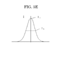
- FIGS. 5A to 5E Examples of a light intensity distribution curve at the cross section including the maximum value of the laser light when the intensity distribution of the laser light traveling onto the thermoreversible recording medium is changed are shown in FIGS. 5A to 5E .
- FIG. 5E shows Gauss distribution, and in such the light intensity distribution in which the light intensity of the center portion is high, I 2 becomes smaller compared with I 1 and thus the value of I 1 /I 2 becomes large.
- I 2 becomes larger against I 1 and thus the value of I 1 /I 2 becomes smaller than that of the light intensity distribution of FIG. 5E .
- the ratio I 1 /I 2 represents the shape of the light intensity distribution of the laser light.
- the ratio I 1 /I 2 when the ratio I 1 /I 2 is more than 2.00, the center portion of the light intensity becomes strong, excessive energy is applied to the thermoreversible recording medium, and as a result some of an image may be remained without being erased due to the deterioration of the thermoreversible recording medium after the repetitive image recording.
- the ratio I 1 /I 2 is less than 0.40, energy is not applied to the center portion compared to the peripheric portion, a center portion of an image is not colored when the image is recorded, and the line is separated into two.
- the radiation energy is increased so as to color the center portion of the line, the light intensity of the peripheric portion becomes to high, excessive energy is applied thereto, and some of the image is remained without being erased at the time of image erasing due to the deterioration of the thermoreversible recording medium.
- the ratio I 1 /I 2 is more than 1.59, the light intensity distribution becomes the one in which the center portion of the light intensity is higher than the surrounding portions of the light intensity, a thickness of a drawing line can be changed by adjusting the radiation power without changing the radiation distance at the same time as suppressing the deterioration of the thermoreversible recording medium due to the repetitive image recording and erasing.
- the lower limit of the aforementioned ratio is preferably 0.40, more preferably 0.50, yet more preferably 0.60, yet even more preferably 0.70.
- the upper limit of the aforementioned ratio is preferably 2.00, more preferably 1.90, yet more preferably 1.80, yet even more preferably 1.70.
- a method for changing the light intensity distribution of the laser light from Gauss distribution to the one in which the light intensity I 1 of the center location of the laser light and the light intensity I 2 at the 80% plane of the total radiation energy of the laser light satisfies the relationship of 0.40 ⁇ I 1 /I 2 ⁇ 2.00 is suitably selected depending on the intended purpose without any restriction.
- the method using a light intensity adjusting unit is particularly preferable.
- the shape of the light intensity distribution of the laser light passing through the center portion of the f ⁇ lens and traveling onto the thermoreversible recording medium differs from that of the laser light passing through the peripheric portion of the f ⁇ lens and traveling onto the thermoreversible recording medium resulted from the use of an optical lens.
- the laser light passing through the center portion of the f ⁇ lens and traveling onto the thermoreversible recording medium is adjusted to as to have the light intensity distribution as shown in FIG.
- thermoreversible recording medium wish the laser light passing through the peripheric portion of the f ⁇ lens and traveling onto the thermoreversible recording medium is deteriorated faster than the irradiated portion thereof with the laser light passing through the center portion of the f ⁇ lens and traveling onto the thermoreversible recording medium.
- the output of the laser light passing through the peripheric portion of the f ⁇ lens and traveling onto the thermoreversible recording medium is adjusted to be lower than that of the laser light passing through the center portion of the f ⁇ lens and traveling onto the thermoreversible recording medium, or the scanning linear velocity of the laser light passing through the peripheric portion of the f ⁇ lens and traveling onto the thermoreversible recording medium is adjusted to be higher than that of the laser light passing through the center portion of the f ⁇ lens and traveling onto the thermoreversible recording medium.
- the image recording and image erasing mechanism includes an aspect in which transparency reversibly changes depending upon temperature, and an aspect in which color tone reversibly changes depending upon temperature.
- the change in the transparency is viewed based upon the following phenomena.
- particles of the low-molecular organic material dispersed in a resin base material and the resin base material are closely attached to each other without spaces, and there is no void inside the particles; therefore, a beam that has entered from one side permeates to the other side without diffusing, and thus the thermoreversible recording medium appears transparent.
- the particles of the low-molecular organic material are formed by fine crystals of the low-molecular organic material, and there are spaces (voids) created at the interfaces between the crystals or the interfaces between the particles and the resin base material; therefore, a beam that has entered from one side is refracted at the interfaces between the voids and the crystals or the interfaces between the voids and the resin and thereby diffuses, and thus the thermoreversible recording medium appears white.
- thermoreversible recording medium having a thermoreversible recording layer (hereinafter otherwise referred to as "recording layer") formed by dispersing the low-molecular organic material in the resin is shown in FIG. 7A .
- the recording layer is in a white turbid opaque state (A), for example, at normal temperature that is lower than or equal to the temperature T 0 . Once the recording layer is heated, it gradually becomes transparent as the temperature exceeds the temperature T 1 . When heated to a temperature between the temperatures T 2 and T 3 , the recording layer becomes transparent (B). The recording layer remains transparent (D) even if the temperature is brought back to normal temperature that is lower than or equal to T 0 .
- A white turbid opaque state
- the recording layer When further heated to a temperature higher than or equal to the temperature T 4 , the recording layer comes into a semitransparent state (C) that is between the maximum transparency and the maximum opacity.
- C semitransparent state
- the recording layer returns to the white turbid opaque state (A) it was in at the beginning, without coming into the transparent state again. It is inferred that this is because the low-molecular organic material completely melts at a temperature higher than or equal to T4, then comes into a supercooled state and crystallizes at a temperature a little higher than T 0 , and on this occasion, the resin cannot adapt to a volume change of the particles caused by the crystallization, which leads to creation of voids.
- the ratio (I 1 /I 2 ) in the intensity distribution of the laser beam is preferably 1.29 or less, and more preferably 1.25 or less.
- FIG. 7B one long-chain low-molecular material particle 31 and a polymer 32 around it are viewed, and changes related to creation and disappearance of a void 33, caused by heating and cooling, are shown.
- a white turbid state A
- a void is created between the polymer and the low-molecular material particle (or inside the particle), and thus there is a state of light diffusion.
- Ts softening temperature
- the low-molecular material particle When cooling is carried out from this temperature to room temperature, the low-molecular material particle is supercooled and crystallizes at a temperature lower than or equal to the softening temperature of the polymer; at this time, the polymer around the low-molecular material particle is in a glassy state and therefore cannot adapt to a volume reduction of the low-molecular material particle caused by the crystallization; thus a void is created, and the white turbid state (A) is reproduced.
- FIG. 8A shows an example of the temperature - color-developing density change curve of a thermoreversible recording medium which has a thermoreversible recording layer formed of the resin containing the leuco dye and the developer.
- FIG. 8B shows the color-developing and color-erasing mechanism of the thermoreversible recording medium which reversibly changes by heat between a transparent state and a color-developed state.
- the recording layer in a colorless state (A) when the recording layer in a colorless state (A) is raised in temperature, the leuco dye and the developer melt and mix at the melting temperature T 1 , thereby developing color, and the recording layer thusly comes into a melted and color-developed state (B).
- the recording layer in the melted and color-developed state (B) is rapidly cooled, the recording layer can be lowered in temperature to room temperature, with its color-developed state kept, and it thusly comes into a color-developed state (C) where its color-developed state is stabilized and fixed.
- this color-developed state depends upon the temperature decreasing rate from the temperature in the melted state: in the case of slow cooling, the color is erased in the temperature decreasing process, and the recording layer returns to the colorless state (A) it was in at the beginning, or comes into a state where the density is low in comparison with the density in the color-developed state (C) produced by rapid cooling.
- the recording layer in the color-developed state (C) is raised in temperature again, the color is erased at the temperature T 2 lower than the color-developing temperature (from D to E), and when the recording layer in this state is lowered in temperature, it returns to the colorless state (A) it was in at the beginning.
- the color-developed state (C) obtained by rapidly cooling the recording layer in the melted state is a state where the leuco dye and the developer are mixed together such that their molecules can undergo contact reaction, which is often a solid state.
- This state is a state where a melted mixture (color-developing mixture) of the leuco dye and the developer crystallizes, and thus color development is maintained, and it is inferred that the color development is stabilized by the formation of this structure.
- the colorless state is a state where the leuco dye and the developer are phase-separated.
- this state is a state where molecules of at least one of the compounds gather to constitute a domain or crystallize, and thus a stabilized state where the leuco dye and the developer are separated from each other by the occurrence of the flocculation or the crystallization.
- phase separation of the leuco dye and the developer is brought about, and the developer crystallizes in this manner, thereby enabling color erasure with greater completeness.
- the aggregation structure changes at T 2 , causing phase separation and crystallization of the developer.
- thermoreversible recording medium when the temperature of the recording layer is repeatedly raised to the temperature T 3 higher than or equal to the melting temperature T 1 , there may be caused such an erasure failure that an image cannot be erased even if the recording layer is heated to an erasing temperature. It is inferred that this is because the developer thermally decomposes and thus hardly flocculates or crystallizes, which makes it difficult for the developer to separate from the leuco dye. Degradation of the thermoreversible recording medium caused by repeated use can be reduced by decreasing the difference between the melting temperature T 1 and the temperature T 3 in FIG. 8A when the thermoreversible recording medium is heated.
- thermoreversible recording medium used in the image processing method of the present invention includes at least a support, a reversible thermosensitive recording layer and a photothermal conversion layer, and further includes other layers suitably selected in accordance with the necessity, such as an photothermal conversion layer, an ultraviolet absorbing layer, first and second oxygen barrier layers, a protective layer, an intermediate layer, an undercoat layer, a back layer, an adhesion layer, a tackiness layer, a colored layer, an air layer and a light-reflecting layer.
- layers suitably selected in accordance with the necessity, such as an photothermal conversion layer, an ultraviolet absorbing layer, first and second oxygen barrier layers, a protective layer, an intermediate layer, an undercoat layer, a back layer, an adhesion layer, a tackiness layer, a colored layer, an air layer and a light-reflecting layer.
- Each of these layers may have a single-layer structure or a laminated structure.
- the shape, structure, size and the like of the support are suitably selected depending on the intended purpose without any restriction.
- Examples of the shape include plate-like shapes; the structure may be a single-layer structure or a laminated structure; and the size may be suitably selected according to the size of the thermoreversible recording medium, etc.
- Examples of the material for the support include inorganic materials and organic materials.
- the organic materials include paper, cellulose derivatives such as cellulose triacetate, synthetic paper, and films made of polyethylene terephthalate, polycarbonates, polystyrene, polymethyl methacrylate, etc.
- the organic materials are preferable, particularly films made of polyethylene terephthalate, polycarbonates, polymethyl methacrylate, etc. are preferable. Of these, polyethylene terephthalate is particularly preferable.
- the support be subjected to surface modification by means of corona discharge, oxidation reaction (using chromic acid, for example), etching, facilitation of adhesion, antistatic treatment, etc. for the purpose of improving the adhesiveness of a coating layer.
- the support white by adding, for example, a white pigment such as titanium oxide to the support.
- the thickness of the support is suitably selected depending on the intended purpose without any restriction, with the range of 10 ⁇ m to 2,000 ⁇ m being preferable and the range of 50 ⁇ m to 1,000 ⁇ m being more preferable.
- the material in which transparency or color tone reversibly changes depending upon temperature is a material capable of exhibiting a phenomenon in which visible changes are reversibly produced by temperature change; and the material can relatively change into a color-developed state and into a colorless state, depending upon the heating temperature and the cooling rate after heating.
- the visible changes can be classified into changes in the state of color and changes in shape.
- the changes in the state of color stem from changes in transmittance, reflectance, absorption wavelength, the degree of diffusion, etc., for example.
- the state of the color of the thermoreversible recording medium in effect, changes due to a combination of these changes.
- the material in which transparency or color tone reversibly changes depending upon temperature is suitably selected from known materials without any restriction.
- two or more types of polymers are mixed and the color of the mixture becomes transparent or white turbid depending on compatibility (refer to JP-A 61-258853 ), a material taking advantage of phase change of a liquid crystal polymer (refer to JP-A 62-66990 ), a material which comes into a state of first color at a first specific temperature which is higher than normal temperature, and comes into a state of second color by heating at a second specific temperature which is higher than the first specific temperature, and then cooling.
- a material in which the color changes according to the first specific temperature and the second specific temperature is particularly preferable in that the temperature can be easily controlled and high contrast can be obtained.
- thermoreversible recording medium including a resin base material and a low-molecular organic material such as a higher fatty acid dispersed in the resin base material is advantageous in that a second specific temperature and a first specific temperature are relatively low, and so erasure and recording can be performed with low energy. Also, since the color-developing and color-erasing mechanism is a physical change which depends upon solidification of the resin and crystallization of the low-molecular organic material, the thermoreversible recording medium offers high environment resistance.
- thermoreversible recording medium which uses the after-mentioned leuco dye and reversible developer and which develops color at a second specific temperature and loses the color at a first specific temperature, exhibits a transparent state and a color-developed state reversibly and exhibits black, blue or other color in the color-developed state; therefore, a high-contrast image can be obtained.
- the low-molecular organic material (which is dispersed in the resin base material and which comes into a transparent state at the first specific temperature and comes into a white turbid state at the second specific temperature) in the thermoreversible recording medium is suitably selected depending on the intended purpose without any restriction, provided that it can change from a polycrystalline material to a single-crystal material by heat in the recording layer.
- a material having a melting temperature of approximately 30°C to 200°C can be used therefor, preferably a material having a melting temperature of 50°C to 150°C.
- Each of these compounds preferably has 10 to 60 carbon atoms, more preferably 10 to 38 carbon atoms, most preferably 10 to 30 carbon atoms.
- Alcohol groups in the esters may or may not be saturated, and may be halogen-substituted.
- the low-molecular organic material preferably has in its molecules at least one selected from oxygen, nitrogen, sulfur and halogens, for example groups such as -OH, -COOH, -CONH-, -COOR, -NH-, -NH 2 , -S-, -S-S- and -O-, and halogen atoms.
- More specific examples of these compounds include higher fatty acids such as lauric acid, dodecanoic acid, myristic acid, pentadecanoic acid, palmitic acid, stearic acid, behenic acid, nonadecanoic acid, arachidonic acid and oleic acid; and esters of higher fatty acids such as methyl stearate, tetradecyl stearate, octadecyl stearate, octadecyl laurate, tetradecyl palmitate and dodecyl behenate.
- higher fatty acids such as lauric acid, dodecanoic acid, myristic acid, pentadecanoic acid, palmitic acid, stearic acid, behenic acid, nonadecanoic acid, arachidonic acid and oleic acid
- esters of higher fatty acids such as methyl stearate, tetradecyl stearate, octa
- the low-molecular organic material used in the third aspect of the image processing method is preferably selected from higher fatty acids among these compounds, more preferably higher fatty acids having 16 or more carbon atoms such as palmitic acid, stearic acid, behenic acid and lignoceric acid, even more preferably higher fatty acids having 16 to 24 carbon atoms.
- the resin base material forms a layer in which the low-molecular organic material is uniformly dispersed and held, and the resin base material affects the transparency when the thermoreversible recording medium becomes most transparent.
- the resin base material is preferably a resin which is highly transparent, mechanically stable and excellent in film-forming property.
- Such a resin is not particularly limited and may be suitably selected in accordance with the intended use.
- examples thereof include polyvinyl chloride; vinyl chloride copolymers such as vinyl chloride-vinyl acetate copolymers, vinyl chloride-vinyl acetate-vinyl alcohol copolymers, vinyl chloride-vinyl acetate-maleic acid copolymers and vinyl chloride-acrylate copolymers; polyvinylidene chloride; vinylidene chloride copolymers such as vinylidene chloride-vinyl chloride copolymers and vinylidene chloride-acrylonitrile copolymers; polyesters; polyamides; polyacrylates, polymethacrylates and acrylate-methacrylate copolymers; and silicone resins. Each of these may be used alone or in combination with two or more.
- the mass ratio of the low-molecular organic material to the resin (resin base material) in the recording layer is preferably in the range of approximately 2:1 to 1:16, more preferably in the range of approximately 1:2 to 1:8.
- the amount of the resin contained is so small as to be outside the mass ratio 2:1, it may be difficult to form a film in which the low-molecular organic material is held in the resin base material.
- the amount of the resin contained is so large as to be outside the mass ratio 1:16, the amount of the low-molecular organic material is small, and thus it may be difficult to make the recording layer opaque.
- a high-boiling solvent and a surfactant may be added into the recording layer for the purpose of making it easier to record a transparent image.
- the method for producing the recording layer is suitably selected depending on the intended purpose without any restriction.
- the recording layer can be produced as follows: a solution dissolving the resin base material and the low-molecular organic material, or a dispersion solution produced by dispersing the low-molecular organic material in the form of fine particles into a solution containing the resin base material (a solvent contained herein does not dissolve at least one selected from the above-mentioned low-molecular organic materials) is applied onto the support and dried.
- the solvent used for producing the recording layer is suitably selected depending on the types of the resin base material and the low-molecular organic material without any restriction.
- the solvent include tetrahydrofuran, methyl ethyl ketone, methyl isobutyl ketone, chloroform, carbon tetrachloride, ethanol, toluene and benzene.
- leuco dyes based upon fluoran and phthalide are particularly preferable in that they are excellent in color-developing and color-erasing property, colorfulness and storage ability. Each of these may be used alone or in combination with two or more, and the thermoreversible recording medium can be made suitable for multicolor or full-color recording by providing a layer which develops color with a different color tone.
- the reversible developer is suitably selected depending on the intended purpose without any restriction, provided that it is capable of reversibly developing and erasing color by means of heat.
- Suitable examples thereof include a compound having in its molecules at least one of the following structures: a structure (1) having such a color-developing ability as makes the leuco dye develop color (for example, a phenolic hydroxyl group, a carboxylic acid group, a phosphoric acid group, etc.); and a structure (2) which controls cohesion among molecules (for example, a structure in which long-chain hydrocarbon groups are linked together).
- the long-chain hydrocarbon group may be bonded via a divalent or more bond group containing a hetero atom.
- the long-chain hydrocarbon groups may contain at least either similar linking groups or aromatic groups.
- phenol is particularly suitable.
- long-chain hydrocarbon groups having 8 or more carbon atoms, preferably 11 or more carbon atoms, are suitable, and the upper limit of the number of carbon atoms is preferably 40 or less, more preferably 30 or less.
- phenolic compounds represented by General Formula (1) are desirable, and phenolic compounds represented by General Formula (2) are more desirable.
- R 1 denotes a single bond or an aliphatic hydrocarbon group having 1 to 24 carbon atoms.
- R 2 denotes an aliphatic hydrocarbon group having two or more carbon atoms, which may have a substituent, and the number of the carbon atoms is preferably 5 or greater, more preferably 10 or greater.
- R 3 denotes an aliphatic hydrocarbon group having 1 to 35 carbon atoms, and the number of the carbon atoms is preferably 6 to 35, more preferably 8 to 35.
- Each of these aliphatic hydrocarbon groups may be provided alone or in combination with two or more.
- R 1 , R 2 and R 3 The sum of the numbers of carbon atoms which R 1 , R 2 and R 3 have is suitably selected depending on the intended purpose without any restriction, with its lower limit being preferably 8 or greater, more preferably 11 or greater, and its upper limit being preferably 40 or less, more preferably 35 or less.
- Each of the aliphatic hydrocarbon groups may be a straight-chain group or a branched-chain group and may have an unsaturated bond, with preference being given to a straight-chain group.
- substituent bonded to the aliphatic hydrocarbon group include hydroxyl group, halogen atoms and alkoxy groups.
- X and Y may be identical or different, each denoting an N atom-containing or O atom-containing divalent group. Specific examples thereof include oxygen atom, amide group, urea group, diacylhydrazine group, diamide oxalate group and acylurea group, with amide group and urea group being preferable.
- n denotes an integer of 0 to 1.
- the electron-accepting compound (developer) be used together with a compound as a color erasure accelerator having in its molecules at least one of -NHCO- group and -OCONH- group because intermolecular interaction is induced between the color erasure accelerator and the developer in a process of producing a colorless state and thus there is an improvement in color-developing and color-erasing property.
- the color erasure accelerator is suitably selectred depending on the intended purpose without any restriction.
- a binder resin and, if necessary, additives for improving or controlling the coating properties and color-developing and color-erasing properties of the recording layer may be used.
- additives include a surfactant, a conductive agent, a filling agent, an antioxidant, a light stabilizer, a color development stabilizer and a color erasure accelerator.
- the binder resin is suitably selected depending on the intended purpose without any restriction, provided that it enables the recording layer to be bonded onto the support.
- one of conventionally known resins or a combination of two or more thereof may be used for the binder resin.
- resins capable of being cured by heat, an ultraviolet ray, an electron beam or the like are preferable in that the durability at the time of repeated use can be improved, with particular preference being given to thermosetting resins each containing an isocyanate-based compound or the like as a cross-linking agent.
- the mixture ratio (mass ratio) of the color developer to the binder resin in the recording layer is preferably in the range of 1:0.1 to 1:10.
- the recording layer may be deficient in thermal strength.
- the amount of the binder resin is too large, it is problematic because the color-developing density decreases.
- the cross-linking agent is suitably selected depending on the intended purpose without any restriction, and examples thereof include isocyanates, amino resins, phenol resins, amines and epoxy compounds. Among these, isocyanates are preferable, and polyisocyanate compounds each having a plurality of isocyanate groups are particularly preferable.
- the ratio of the number of functional groups contained in the cross-linking agent to the number of active groups contained in the binder resin is preferably in the range of 0.01:1 to 2:1.
- the amount of the cross-linking agent added is so small as to be outside this range, sufficient thermal strength cannot be obtained.
- the amount of the cross-linking agent added is so large as to be outside this range, there is an adverse effect on the color-developing and color-erasing properties.
- the gel fraction of any of the thermosetting resins in the case where thermally cross-linked is preferably 30% or greater, more preferably 50% or greater, even more preferably 70% or greater. When the gel fraction is less than 30%, an adequate cross-linked state cannot be produced, and thus there may be degradation of durability.
- these two states can be distinguished by immersing a coating film in a solvent having high dissolving ability, for example. Specifically, with respect to the binder resin in a non-cross-linked state, the resin dissolves in the solvent and thus does not remain in a solute.
- the above-mentioned other components in the recording layer are suitably selected depending on the intended purpose without any restriction.
- a surfactant, a plasticizer and the like are suitable therefor in that recording of an image can be facilitated.
- a coating solution dispersing device To prepare the recording layer coating solution, materials may be together dispersed into a solvent using the dispersing device; alternatively, the materials may be independently dispersed into respective solvents and then the solutions may be mixed together. Further, the ingredients may be heated and dissolved, and then they may be precipitated by rapid cooling or slow cooling.
- the solvent used in (1) or (2) cannot be unequivocally defined, as it is affected by the types, etc. of the resin, the electron-donating color-forming compound and the electron-accepting compound.
- examples thereof include tetrahydrofuran, methyl ethyl ketone, methyl isobutyl ketone, chloroform, carbon tetrachloride, ethanol, toluene and benzene.
- the electron-accepting compound is present in the recording layer, being dispersed in the form of particles.
- Pigments, an antifoaming agent, a dispersant, a slip agent, an antiseptic agent, a cross-linking agent, a plasticizer and the like may be added into the recording layer coating solution, for the purpose of exhibiting high performance as a coating material.
- the coating method for the recording layer is suitably selected depending on the intended purpose without any restriction.
- a support which is continuous in the form of a roll or which has been cut into the form of a sheet is conveyed, and the support is coated with the recording layer by a known method such as blade coating, wire bar coating, spray coating, air knife coating, bead coating, curtain coating, gravure coating, kiss coating, reverse roll coating, dip coating or die coating.
- the drying conditions of the recording layer coating solution are suitably selected depending on the intended purpose without any restriction.
- the recording layer coating solution is dried at room temperature (25°C) to a temperature of 140°C, for approximately 10 sec to 10 min.
- the thickness of the recording layer is suitably selected depending on the intended purpose without any restriction. For instance, it is preferably 1 ⁇ m to 20 ⁇ m, more preferably 3 ⁇ m to 15 ⁇ m.
- the contrast of an image may lower because the color-developing density lowers.
- the heat distribution in the layer increases, a portion which does not reach a color-developing temperature and so does not develop color is created, and thus a desired color-developing density may be unable to be obtained.
- the photothermal conversion layer is a layer having a function to absorb laser beams and generate heat.
- the photothermal conversion layer at least contains a photothermal conversion material having a function to absorb the laser beam at high efficiency and then generate heat. It is particularly preferable that the photothermal conversion material is contained in the thermoreversible recording layer, or at least one of the adjacent layers of the thermoreversible recording layer. In the case where the photothermal conversion material is contained in the thermoreversible recording layer, the thermoreversible recording layer also functions as a photothermal conversion layer.
- thermoreversible recording layer and the photothermal conversion layer being adjacently disposed means that the photothermal conversion layer is disposed so as to be in contact with the thermoreversible recording layer, or the photothermal conversion layer is disposed on the thermoreversible recording layer via a layer having a thickness thinner than the thickness of the thermoreversible recording layer.
- the photothermal conversion material is broadly classified into inorganic materials and organic materials.
- the inorganic materials include carbon black, metals such as Ge, Bi, In, Te, Se, and Cr, or semi-metals thereof or alloys thereof. Each of these inorganic materials is formed into a layer form by vacuum evaporation method or by bonding a particulate material to a layer surface using a resin or the like.
- various dyes can be suitably used in accordance with the wavelength of light to be absorbed, however, when a semiconductor laser is used as a light source, a near-infrared absorption pigment having an absorption peak near wavelengths of 700 nm to 1,500 nm.
- a near-infrared absorption pigment having an absorption peak near wavelengths of 700 nm to 1,500 nm.
- Specific examples thereof include cyanine pigments, quinone pigments, quinoline derivatives of indonaphthol, phenylene diamine-based nickel complexes, phthalocyanine compounds, and naphthalocyanine compounds.
- a photothermal conversion material that is excellent in heat resistance.
- Each of the near-infrared absorption pigments may be used alone or in combination with two or more.
- the photothermal conversion material is typically used in combination with a resin.
- the resin used in the photothermal conversion layer is suitably selected from among those known in the art without any restriction, provided that it can maintain the inorganic material and the organic material therein, however, thermoplastic resins and thermosetting resins are preferable, and those similar to the binder resin used in the recording layer can be suitably used.
- resins curable with the application of heat, ultraviolet light, or an electron beam can be preferably used for improving the durability against the repetitive use, and a thermal crosslinkable resin using an isocyanate compound is particularly preferable.
- the binder resin preferably has a hydroxyl value of 100 mgKOH/g to 400 mgKOH/g.
- an ultraviolet absorbing layer is preferably disposed on the thermoreversible recording layer for preventing residual images from erasure due to coloring of the leuco dye contained in the thermoreversible recording layer by ultraviolet light and photodeterioration thereof.
- the light resistance of the recording medium is improved.
- the light resistance of the recording medium can be significantly improved by appropriately adjusting the thickness of the ultraviolet absorbing layer so as to absorb ultraviolet light having a wavelength of 390 nm or shorter.
- the ultraviolet absorbing layer at least contains a binder resin and an ultraviolet absorber, and may further contain other components such as filler, lubricants, color pigments and the like, if necessary.
- the binder resin is suitably selected depending on the intended purpose without any restriction.
- the binder resin used in the thermoreversible recording layer, or resinous substances such as thermoplastic resins and thermosetting resins can be used as the binder resin.
- the resinous substances include polyethylene, polypropylene, polystyrene, polyvinyl alcohol, polyvinyl butyral, polyurethane, saturated polyester, unsaturated polyester, epoxy resin, phenol resin, polycarbonate, and polyamide.
- ultraviolet absorbing polymer a polymer having an ultraviolet absorbing structure (hereinafter, may be referred as "ultraviolet absorbing polymer”), as the ultraviolet absorber.
- the polymer having the ultraviolet absorbing structure means a polymer having an ultraviolet absorbing structure (e.g. an ultraviolet absorbing group) in the molecule thereof.
- the ultraviolet absorbing structure include a salicylate structure, a cyanoacrylate structure, a benzotriazol structure, and a benzophenone structure.
- the benzotriazol structure and the benzophenone structure are particularly preferable as they absorb the ultraviolet light having a wavelength of 340 nm to 400 nm which is a factor to cause a photodeterioration of the leuco dye.
- the thermoreversible recording medium may be formed into a desired shape according to its use, for example into a card, a tag, a label, a sheet or a roll.
- the thermoreversible recording medium in the form of a card can be used for prepaid cards, discount cards, credit cards and the like.
- the thermoreversible recording medium in the form of a tag that is smaller in size than the card can be used for price tags and the like.
- the thermoreversible recording medium in the form of a tag that is larger in size than the card can be used for tickets, sheets of instruction for process control and shipping, and the like.
- thermoreversible recording member used in the present invention is superior in convenience because the recording layer capable of reversible display, and an information storage section are provided on the same card or tag (so as to form a single unit), and part of information stored in the information storage section is displayed on the recording layer, thereby making it is possible to confirm the information by simply looking at a card or a tag without needing a special device. Also, when information stored in the information storage section is rewritten, rewriting of information displayed by the thermoreversible recording member makes it possible to use the thermoreversible recording medium repeatedly as many times as desired.
- thermoreversible recording member includes the recording layer capable of reversible display, and the information storage section.
- Suitable examples of the information storage section include an RF-ID tag.
- FIG. 9 shows a schematic diagram of an example of an RF-ID tag 85.
- This RF-ID tag 85 is composed of an IC chip 81, and an antenna 82 connected to the IC chip 81.
- the IC chip 81 is divided into four sections, i.e. a storage section, a power adjusting section, a transmitting section and a receiving section, and communication is conducted as they perform their operations allotted.
- the RF-ID tag communicates with an antenna of a reader/writer by means of a radio wave so as to transfer data.
- an electromagnetic induction method in which the antenna of the RF-ID tag receives a radio wave from the reader/writer, and electromotive force is generated by electromagnetic induction caused by resonance; and a radio wave method in which electromotive force is generated by a radiated electromagnetic field.
- the IC chip inside the RF-ID tag is activated by an electromagnetic field from outside, information inside the chip is converted to a signal, then the signal is emitted from the RF-ID tag. This information is received by the antenna on the reader/writer side and recognized by a data processing unit, then data processing is carried out on the software side.
- the RF-ID tag is formed into a label or a card and can be affixed to the thermoreversible recording medium.
- the RF-ID tag may be affixed to the recording layer surface or the back layer surface, desirably to the back surface layer.
- a known adhesive or tackiness agent may be used to stick the RF-ID tag and the thermoreversible recording medium together.
- thermoreversible recording medium When the wavelength is in the visible region, an additive for absorbing the laser light and generating the heat for image recording and image erasing of the thermoreversible recording medium is colored by the laser beam, and thus may lower the contrast of the image.
- the wavelength of the laser light emitted from the CO 2 laser is 10.6 ⁇ m which is in the far infrared region, and the thermoreversible recording medium absorbs such laser light. Therefore, it is not necessary to add the additive for absorbing the laser light and generating heat for image recording and image erasing of the thermoreversible recording medium. Moreover, this additive may absorb the visible light, even through it is a slight degree, when the laser light having a wavelength in the near infrared region is used. Therefore, the use of the CO 2 laser that does not require the additive has an advantage, as lowing of the image contrast can be prevented.
- the wavelength of the laser light emitted from the YAG laser, fiber laser, and LD is in the visible to near infrared region (a free hundred micrometers to 1.2 ⁇ m). Since the currently available thermoreversible recording medium does not absorb the laser light in this wavelength region, it is necessary to add a photo thermal conversion material for absorbing the laser light and converting to heat. But still, the use of such lasers has an advantage such that recording of highly precise images can be realized because the wavelength of the laser light is short.
- the YAG laser and fiber laser have high output, there is an advantage such that image recording and image erasing can be high speeded.
- the LD has an advantage such that the device can be downsized and moreover the price of the device can be set low, as the laser itself is small.
- the arrangement of the light intensity distribution adjusting unit is not particularly limited provided that it is disposed on a surface from which a laser beam is emitted in the laser beam emitting unit; the distance, etc. between the light intensity distribution adjusting unit and the laser beam emitting unit may be suitably selected in accordance with the intended use, and the light intensity distribution adjusting unit is preferably placed between the laser beam emitting unit and the after-mentioned galvano mirror, more preferably between the after-mentioned beam expander and the galvano mirror.
- the light intensity distribution adjusting unit has the function to change the light intensity distribution such that the ratio (I 1 /I 2 ) of the light intensity (I 1 ) of the applied laser beam in a central position of the applied laser beam to the light intensity (I 2 ) of the applied laser beam on a plane corresponding to 80% of the total irradiation energy of the applied laser beam satisfies 0.4 ⁇ I 1 /I 2 ⁇ 2.0. Therefore, it is possible to reduce degradation of the thermoreversible recording medium caused by repeated image recording and erasure and to improve durability against repeated use, with the image contrast being maintained.
- the light intensity distribution adjusting unit is suitably selected depending on the intended purpose without any restriction. Suitable examples thereof include lenses, filters, masks, mirrors and fiber couplings, with lenses being preferable because of causing less energy loss, specifically kaleidoscopes, integrators, beam homogenizers, aspheric beam shapers (each of which is a combination of an intensity transformation lens and a phase correction lens), aspherical lenses, and diffractive optical elements.
- aspherical lenses as shown in FIG. 6B is particularly preferable, because of high degree of design flexibility in the intensity distribution adjusting element.
- the light intensity can be controlled by adjusting the distance between the thermoreversible recording medium and the f ⁇ lens which is a condenser lens so as not to be identical to the focal length, together with the aspherical lens shown in FIG. 6B .
- the f ⁇ lens is an element for condensing the laser light onto the thermoreversible recording medium.
- a diameter of a condensed beam by a conventional convex lens is varied depending on the scanning position, as the distance from a condenser lens (including the convex lens and a f ⁇ lens) is changed depending on the scanning position on the thermoreversible recording medium.
- Use of the f ⁇ lens is preferable in this case because the diameter of the condensed beam can be maintained at a constant level regardless of the scanning position on the thermoreversible recording medium.
- FIG. 6A one example of the image processing device of the present invention, mainly the laser light emitting unit, is shown in FIG. 6A .
- the oscillator unit contains a laser oscillator 1, a beam expander 2, a scanning unit 5, and the like.
- the power supply controlling unit contains a power supply for discharging (in the case of a CO 2 laser) or a driving power supply (a YAG laser etc.) of a light source configured to excite a laser medium, a driving power supply for the galvanometer, a power supply for cooling such as Peltier element, and a control unit for controlling the entire image processing device.
- the program unit is a unit configured to input conditions such as an intensity, scanning velocity and the light of laser light, form and edit characters to be recorded or the like for image recording or image erasing based on input from a touch-panel or keyboard.
- the image processing method and image processing device of the present invention are capable of repetitively performing image recording and image erasing to a thermoreversible recording medium such as a label attached to a container such as a cardboard box or a plastic container in a non-contact system.
- the image processing method and image processing device of the present invention are capable of suppressing the deterioration of the thermoreversible recording medium due to the repetitive use.
- the image processing method and image processing device of the present invention are especially suitably used for distribution and delivery systems.
- an image can be recorded on and erased from the label while transferring the cardboard box or plastic container placed on the conveyer belt, and thus the time required for shipping can be reduced as it is not necessary to stop the production line.
- the label attached to the cardboard box or plastic container can be reused in the same state, and image erasing and recording can be performed again without removing the label from the cardboard box or plastic container.
- thermoreversible recording medium in which color tone changed reversibly (transparent state - color-developed state) depending upon temperature was produced in the following manner.
- a white turbid polyester film (TETORON FILM U2L98W, manufactured by Teijin DuPont Films Japan Limited) having a thickness of 125 ⁇ m was used.
- the prepared recording layer coating solution was applied, using a wire bar, onto the support over which the under layer had already been formed, and the recording layer coating solution was dried at 100°C for 2min, then cured at 60°C for 24 hr so as to form a recording layer having a thickness of 11 ⁇ m.
- the intermediate layer coating solution was applied, using a wire bar, onto the support over which the under layer and the recording layer had already been formed, and the intermediate layer coating solution was heated and dried at 90°C for 1 min, and then heated at 60°C for 2 hr so as to form an intermediate layer having a thickness of 2 ⁇ m.
- the protective layer coating solution was applied, using a wire bar, onto the support over which the under layer, the recording layer and the intermediate layer had already been formed, and the protective layer coating solution was heated and dried at 90°C for 1 min, then cross-linked by means of an ultraviolet lamp of 80 W/cm, so as to form a protective layer having a thickness of 4 ⁇ m.
- a photopolymerization initiator 184, manufactured by Nih
- thermoreversible recording medium of Production Example 1 was produced.
- thermoreversible recording medium in which transparency changed reversibly (transparent state - white turbid state) depending upon temperature was produced in the following manner.
- a transparent PET film (LUMIRROR 175-T12, manufactured by Toray Industries, Inc.) having a thickness of 175 ⁇ m was used.
- thermosensitive recording layer having a thickness of 10 ⁇ m was provided over the support.
- thermoreversible recording medium of Production Example 2 was produced.
- thermoreversible recording medium of Production Example 3 was prepared in the same manner as in Production Example 1, provided that 0.03 parts by mass of photothermal conversion material (EXCOLOR IR-14, manufactured by NIPPON SHOKUBAI Co., Ltd.) was added to the recording layer in the process of the production of the thermoreversible recording medium.
- photothermal conversion material EXCOLOR IR-14, manufactured by NIPPON SHOKUBAI Co., Ltd.
- the energy of laser light is an energy amount of the laser light emitted on a thermoreversible recording medium per length unit in the scanning direction.
- the intensity distribution of laser light was measured in the following manner.
- the intensity of laser light was measured using a high-power laser beam analyzer (LPK-CO 2 -16, manufactured by Ophir-Spiricon Inc.) by reducing light using a Zn-Se wedge (LBS-100-IR-W, manufactured by Ophir-Spiricon Inc.) and a CaF 2 filter (LBS-100-IR-F, manufactured by Ophir-Spiricon Inc.) so that the laser output was adjusted to be 0.05%. Then, the obtained intensity of the laser light was profiled on a three-dimensional graph to thereby obtain a light intensity distribution of the laser light.
- LBS-100-IR-W manufactured by Ophir-Spiricon Inc.
- CaF 2 filter LBS-100-IR-F
- a laser beam analyzer (Scorpion SCOR-20SCM, manufactured by Point Grey Research, Inc.) was positioned so that the emitting distance was to be identical to the distance at the time of recording a thermoreversible recording medium, and then the intensity of laser light was measured by the laser beam analyzer by reducing light using a beam splitter (BEAMSTAR-FX-BEAM SPLITTER, manufactured by Ophir Optronics Ltd.) that was a combination of a transmissive mirror and a filter so that the output of the laser was adjusted to be 3 ⁇ 10 -6 . Then, the obtained intensity of the laser light was profiled on a three-dimensional graph to thereby obtain a light intensity distribution of the laser light.
- a beam splitter BEAMSTAR-FX-BEAM SPLITTER, manufactured by Ophir Optronics Ltd.
- I 1 was obtained from the light intensity of the center portion of the emitted laser light
- I 2 was obtained from the light intensity of a 80% plane of the total radiation energy of the laser light.
- the area where the laser light was capable of illuminating was set from the central point of the area where the laser light was capable of illuminating to 75 mm through the control of a mirror disposed in the image processing device to which the laser light source was mounted.
- the thermoreversible recording medium was evaluated at the central point of the area where the laser light was capable of illuminating as the center portion of the f ⁇ lens, and at a position which was 60 mm apart from the central point of the area where the laser light was capable of illuminating as the peripheric portion of the f ⁇ lens.
- thermoreversible recording medium of Production Example 1 was used; a laser radiation distance from a f ⁇ lens to the thermoreversible recording medium was adjusted to 184 mm using a CO 2 laser (LP-440, manufactured by SUNX Limited) which was equipped, in a pathway of laser light, at least with an aspherical lens that was an optical lens configured to control a light intensity distribution of laser light, a galvanometer mirror configured to scan the laser light, and the condenser f ⁇ lens (focal length: 189 mm, effective radius R: 32.5 mm) so that the light intensity distribution I 1 /I 2 of the laser light passing through the center portion of the f ⁇ lens and traveling onto the thermoreversible recording medium was adjusted to 1.6.
- CO 2 laser LP-440, manufactured by SUNX Limited
- thermoreversible recording medium An image was recorded on the thermoreversible recording medium under the conditions such that the output and scanning linear velocity of the laser light passing through the center portion of the f ⁇ lens and traveling onto the thermoreversible recording medium were respectively 20 W, and 1,800 mm/s, and the output and scanning linear velocity of the laser light passing through the peripheric portion of the f ⁇ lens and traveling onto the thermoreversible recording medium were respectively 22 W, and was 1,800 mm/s.
- thermoreversible recording medium of Production Example 1 was used, and the image was erased from the thermoreversible recording medium by means of a CO 2 laser (LP-440, manufactured by SUNX Limited) which was equipped, in a pathway of laser light, at least with an aspherical lens that was an optical lens configured to control a light intensity distribution of laser light, a galvanometer mirror configured to scan the laser light, and the condenser f ⁇ lens (focal length: 189 mm, effective radius R: 32.5 mm), adjusting the radiation distance, scanning linear velocity, and spot diameter at 245 mm, 1,750 mm/s, and 3.0 mm, respectively.
- the outputs of the laser irradiating the center portion and peripheric portion of the f ⁇ lens were adjusted to 22 W.
- Image recording and image erasing were carried out in the same manner as in No.1, provided that the output of the laser light passing through the peripheric portion of the f ⁇ lens and traveling onto the thermoreversible recording medium was changed to 20 W in the image recording step.
- Image recording and image erasing were carried out in the same manner as in No.1, provided that the output of the laser light passing through the peripheric portion of the f ⁇ lens and traveling onto the thermoreversible recording medium was changed to 19 W in the image recording step.
- Image recording and image erasing were carried out in the same manner as in No.1, provided that the output of the laser light passing through the peripheric portion of the f ⁇ lens and traveling onto the thermoreversible recording medium was changed to 18 W in the image recording step.
- Image recording and image erasing were carried out in the same manner as in No.1, provided that the output of the laser light passing through the peripheric portion of the f ⁇ lens and traveling onto the thermoreversible recording medium was changed to 14 W in the image recording step.
- thermoreversible recording medium An image was recorded on the thermoreversible recording medium under the conditions such that the output and scanning linear velocity of the laser light passing through the center portion of the f ⁇ lens and traveling onto the thermoreversible recording medium were respectively 20 W, and 1,800 mm/s, and the output and scanning linear velocity of the laser light passing through the peripheric portion of the f ⁇ lens and traveling onto the thermoreversible recording medium were respectively 20 W, and was 1,620 mm/s.
- Image Erasing was carried out in the same manner as in No. 12, provided that the outputs of the laser light passing through the center and peripheric portions of the f ⁇ lens were changed to 13 W.
- Image recording and image erasing were carried out in the same manner as in No. 2, provided that the aspherical lens was removed from the CO 2 laser (LP-440, manufactured by SUNX Limited).
- Table 7-2 Peripheric portion of f ⁇ lens Energy Output Scanning linear velocity E2 P2[W] V2 [mm/s] No. 4 0.01 18 1800 Present invention No. 2 0.011 20 1800 Comp. No. 14 0.011 20 1800 Comp. Table 8-1 Repeating durability Center portion of f ⁇ lens (number) Peripheric portion of f ⁇ lens (number) Evaluation No. 4 390 360 A Present invention No. 2 390 170 B Comp. No. 14 80 90 C Comp. Table 8-2 Image line width Center portion of f ⁇ lens (mm) Peripheric portion of f ⁇ lens (mm) Evaluation No. 4 0.35 0.32 A Present invention No. 2 0.35 0.35 A Comp. No. 14 0.27 0.26 B Comp.
- the aspherical lens was disposed in No. 2, the repeating durability was lowered because the output of the laser light passing through the peripheric portion of the f ⁇ lens was larger than that of No. 4.
- No. 14 was the example where the aspherical lens was removed from No. 2, and the similar level of energy was applied from the laser light passing through the center portion of the f ⁇ lens and traveling onto the thermoreversible recording medium and from the laser light passing through the peripheric portion of the f ⁇ lens and traveling onto the thermoreversible recording medium because the aspherical lens was removed. Accordingly, there was no difference in the repeating durability and image line width between the center portion and the peripheric portion.
- thermoreversible recording medium As the light intensity distribution of the laser light passing through the center portion of the f ⁇ lens and traveling onto the thermoreversible recording medium could not be controlled, resulting in lowering the repeating durability of the irradiated portion.
- thermoreversible recording medium of Production Example 2 was used; a laser radiation distance from a f ⁇ lens to the thermoreversible recording medium was adjusted to 184 mm using a CO 2 laser (LP-440, manufactured by SUNX Limited) which was equipped, in a pathway of laser light, at least with an aspherical lens that was an optical lens configured to control a light intensity distribution of laser light, a galvanometer mirror configured to scan the laser light, and the condenser f ⁇ lens (focal length: 189 mm, effective radius R: 32.5 mm) so that the light intensity distribution I 1 /I 2 of the laser light passing through the center portion of the f ⁇ lens and traveling onto the thermoreversible recording medium was adjusted to 1.6.
- CO 2 laser LP-440, manufactured by SUNX Limited
- thermoreversible recording medium An image was recorded on the thermoreversible recording medium under the conditions such that the output and scanning linear velocity of the laser light passing through the center portion of the f ⁇ lens and traveling onto the thermoreversible recording medium were respectively 18.3 W, and 1,800 mm/s, and the output and scanning linear velocity of the laser light passing through the peripheric portion of the f ⁇ lens and traveling onto the thermoreversible recording medium were respectively 18.3 W, and was 1,800 mm/s.
- thermoreversible recording medium by means of a CO 2 laser (LP-440, manufactured by SUNX Limited) which was equipped, in a pathway of laser light, at least with an aspherical lens that was an optical lens configured to control a light intensity distribution of laser light, a galvanometer mirror configured to scan the laser light, and the condenser f ⁇ lens (focal length: 189 mm, effective radius R: 32.5 mm), adjusting the radiation distance, scanning linear velocity, and spot diameter at 245 mm, 1,750 mm/s, and 3.0 mm, respectively.
- the output of the laser irradiating the center portion and peripheric portion of the f ⁇ lens was adjusted to 19 W.
- the image line width was measured.
- the measurement of the image line width was carried out in the following manner. At first, a gray scale (manufactured by Eastman Kodak Company) was read by a scanner (Canoscan4400, manufactured by Canon Inc.), a correlation was taken between the obtained digital gradation value and a gray level measured by a reflection densitometer (RD-914, manufactured by GretagMacbeth), then the digital gradation value obtained by reading the image recorded as mentioned above by means of the scanner was converted to the gray level, and the width when the gray level became 0.5 or more was calculated from the set pixel number (1,200 dpi) of the digital gradation value as a line width. Thereafter, obtained result was evaluated in the same manner as in Example 1. The results are shown in Tables 10-1 and 10-2.
- the image recording was carried out in the same manner as in Comparative Example 1, provided that the light intensity distribution I 1 /I 2 of the laser light passing through the center portion of the f ⁇ lens and traveling onto the thermoreversible recording medium was changed to 2.3, the output and scanning linear velocity of the laser light passing through the center portion of the f ⁇ lens and traveling onto the thermoreversible recording medium were respectively changed to 18 W, and 1,800 mm/s, and the output and scanning linear velocity of the laser light passing through the peripheric portion of the f ⁇ lens and traveling onto the thermoreversible recording medium were respectively changed to 18 W and 1,980 mm/s.
- thermoreversible recording medium of Production Example 3 was used; a laser radiation distance from a f ⁇ lens to the thermoreversible recording medium was adjusted to 158 mm using a fiber coupling semiconductor laser LIMO25-F100-DL808 manufactured by LIMO GmbH (a center wavelength: 808 nm) which was equipped, in a pathway of laser light, at least with an aspherical lens that was an optical lens configured to control a light intensity distribution of laser light, a galvanometer mirror configured to scan the laser light, and the condenser f ⁇ lens (focal length: 150 mm, effective radius R: 30 mm) so that the light intensity distribution I 1 /I 2 of the laser light passing through the center portion of the f ⁇ lens and traveling onto the thermoreversible recording medium was adjusted to 1.3.
- a fiber coupling semiconductor laser LIMO25-F100-DL808 manufactured by LIMO GmbH (a center wavelength: 808 nm) which was equipped, in a pathway of laser light, at least with an aspherical lens that was
- thermoreversible recording medium An image was recorded on the thermoreversible recording medium under the conditions such that the output and scanning linear velocity of the laser light passing through the center portion of the f ⁇ lens and traveling onto the thermoreversible recording medium were respectively 14 W, and 1,000 mm/s, and the output and scanning linear velocity of the laser light passing through the peripheric portion of the f ⁇ lens and traveling onto the thermoreversible recording medium were respectively 15.4 W, and was 1,000 mm/s.
- the image was erased from the thermoreversible recording medium by means of a fiber coupling semiconductor laser LIMO25-F100-DL808 manufactured by LIMO GmbH (a center wavelength: 808 nm) which was equipped, in a pathway of laser light, at least with an aspherical lens that was an optical lens configured to control a light intensity distribution of laser light, a galvanometer mirror configured to scan the laser light, and the condenser f ⁇ lens (focal length: 189 mm, effective radius R: 30 mm), adjusting the radiation distance, scanning linear velocity, and spot diameter at 195 mm, 500 mm/s, and 3.0 mm, respectively.
- the outputs of the laser irradiating the center portion and peripheric portion of the f ⁇ lens were adjusted to 16.5 W.
- the measurement of the image line width was carried out in the following manner.
- a gray scale manufactured by Eastman Kodak Company
- a scanner Canon Inc.
- RD-914 a reflection densitometer
- the digital gradation value obtained by reading the image recorded as mentioned above by means of the scanner was converted to the gray level, and the width when the gray level became 0.5 or more was calculated from the set pixel number (1,200 dpi) of the digital gradation value as a line width.
- obtained result was evaluated in the same manner as in Example 1. The results are shown in Tables 12-1 and 12-2.
- Image recording and erasing were performed in the same manner as in ⁇ No. 15>>, provided that output of the laser light passing through the peripheric portion of the f ⁇ lens and traveling onto the thermoreversible recording medium was changed to 14 W in the image recording step.
- Image recording and erasing were performed in the same manner as in ⁇ No. 15>>, provided that output of the laser light passing through the peripheric portion of the f ⁇ lens and traveling onto the thermoreversible recording medium was changed to 13.3 W in the image recording step.
- Image recording and erasing were performed in the same manner as in ⁇ No. 15>>, provided that output of the laser light passing through the peripheric portion of the f ⁇ lens and traveling onto the thermoreversible recording medium was changed to 12.6 W in the image recording step.
- Image recording and erasing were performed in the same manner as in ⁇ No. 15>>, provided that output of the laser light passing through the peripheric portion of the f ⁇ lens and traveling onto the thermoreversible recording medium was changed to 11.6 W in the image recording step.
- Image recording and erasing were performed in the same manner as in ⁇ No. 15>>, provided that output of the laser light passing through the peripheric portion of the f ⁇ lens and traveling onto the thermoreversible recording medium was changed to 9.8 W in the image recording step.
- Nos. 16 to 20 were evaluated in terms of the measurements of the image line width and repeating durability in the same manner as in No. 15. The results are shown in Tables 12-1 and 12-2 together with the result of No. 15.
- thermoreversible recording medium An image was recorded on the thermoreversible recording medium under the conditions such that the output and scanning linear velocity of the laser light passing through the center portion of the f ⁇ lens and traveling onto the thermoreversible recording medium were respectively 14 W, and 1,000 mm/s, and the output and scanning linear velocity of the laser light passing through the peripheric portion of the f ⁇ lens and traveling onto the thermoreversible recording medium were respectively 14 W, and was 900 mm/s.
- Image recording and erasing were performed in the same manner as in No. 21, provided that the scanning linear velocity of the laser light passing through the peripheric portion of the f ⁇ lens and traveling onto the thermoreversible recording medium was changed to 1,050 mm/s in the image recording step.
- Image recording and erasing were performed in the same manner as in No. 21, provided that the scanning linear velocity of the laser light passing through the peripheric portion of the f ⁇ lens and traveling onto the thermoreversible recording medium was changed to 1,100 mm/s in the image recording step.
- Image recording and erasing were performed in the same manner as in No. 21, provided that the scanning linear velocity of the laser light passing through the peripheric portion of the f ⁇ lens and traveling onto the thermoreversible recording medium was changed to 1,420 mm/s in the image recording step.
- Nos. 22 to 25 were evaluated in terms of the measurements of the image line width and repeating durability in the same manner as in No. 21. The results are shown in Tables 14-1 and 14-2 together with the result of No. 21.
- Table 13-1 (P2/P1) ⁇ 100 [%] (V2/V1) ⁇ 100 [%] Center portion of f ⁇ lens Light intensity distribution I 1 /I 2 Energy Output Scanning linear velocity E1 P1[W] V1 [mm/s] No. 21 100 90 1.3 0.014 14 1000 Comp. No. 16 100 100 1.3 0.014 14 1000 Comp. No. 22 100 105 1.3 0.014 14 1000 Present invention No. 23 100 111 1.3 0.014 14 1000 Present invention No. 24 100 120 1.3 0.014 14 1000 Present invention No.
- thermoreversible recording medium of Production Example 3 was used; a laser radiation distance from a f ⁇ lens to the thermoreversible recording medium was adjusted to 151 mm using a fiber coupling semiconductor laser LIMO25-F100-DL808 manufactured by LIMO GmbH (a center wavelength: 808 nm) which was equipped, in a pathway of laser light, at least with an aspherical lens that was an optical lens configured to control a light intensity distribution of laser light, a galvanometer mirror configured to scan the laser light, and the condenser f ⁇ lens (focal length: 150 mm, effective radius R: 30 mm) so that the light intensity distribution I 1 /I 2 of the laser light passing through the center portion of the f ⁇ lens and traveling onto the thermoreversible recording medium was adjusted to 1.6.
- a fiber coupling semiconductor laser LIMO25-F100-DL808 manufactured by LIMO GmbH (a center wavelength: 808 nm) which was equipped, in a pathway of laser light, at least with an aspherical lens that was
- thermoreversible recording medium An image was recorded on the thermoreversible recording medium under the conditions such that the output and scanning linear velocity of the laser light passing through the center portion of the f ⁇ lens and traveling onto the thermoreversible recording medium were respectively 11 W, and 1,000 mm/s, and the output and scanning linear velocity of the laser light passing through the peripheric portion of the f ⁇ lens and traveling onto the thermoreversible recording medium were respectively 12.1 W, and was 1,000 mm/s.
- thermoreversible recording medium of Production Example 1 was used, and the image was erased from the thermoreversible recording medium by means of a fiber coupling semiconductor laser LIMO25-F100-DL808 manufactured by LIMO GmbH (a center wavelength: 808 nm) which was equipped, in a pathway of laser light, at least with an aspherical lens that was an optical lens configured to control a light intensity distribution of laser light, a galvanometer mirror configured to scan the laser light, and the condenser f ⁇ lens (focal length: 189 mm, effective radius R: 30 mm), adjusting the radiation distance, scanning linear velocity, and spot diameter at 195 mm, 500 mm/s, and 3.0 mm, respectively.
- the outputs of the laser irradiating the center portion and peripheric portion of the f ⁇ lens were adjusted to 16.5 W.
- Image recording and erasing were performed in the same manner as in No. 26, provided that the output of the laser light passing through the peripheric portion of the f ⁇ lens and traveling onto the thermoreversible recording medium was changed to 11 W in the image recording step.
- Image recording and erasing were performed in the same manner as in No. 26, provided that the output of the laser light passing through the peripheric portion of the f ⁇ lens and traveling onto the thermoreversible recording medium was changed to 10.7 W in the image recording step.
- Image recording and erasing were performed in the same manner as in No. 26, provided that the output of the laser light passing through the peripheric portion of the f ⁇ lens and traveling onto the thermoreversible recording medium was changed to 9.1 W in the image recording step.
- Image recording and erasing were performed in the same manner as in No. 26, provided that the output of the laser light passing through the peripheric portion of the f ⁇ lens and traveling onto the thermoreversible recording medium was changed to 7.7 W in the image recording step.
- Nos. 27 to 31 were evaluated in terms of the measurements of the image line width and repeating durability in the same manner as in No. 26. The results are shown in Tables 16-1 and 16-2 together with the result of No. 26.
- Table 15-1 P2/P1) ⁇ 100 [%] (V2/V1) ⁇ 100 [%] Center portion of f ⁇ lens Light intensity distribution I 1 /I 2 Energy Output Scanning linear velocity E1 P1[W] V1 [mm/s]
- No. 26 110 100 1.6 0.011 11 1000 Comp. No. 27 100 100 1.6 0.011 11 1000 Comp. No. 28 97 100 1.6 0.011 11 1000 Present invention No. 29 90 100 1.6 0.011 11 1000 Present invention No. 30 83 100 1.6 0.011 11 1000 Present invention No.
- thermoreversible recording medium of Production Example 3 was used; a laser radiation distance from a f ⁇ lens to the thermoreversible recording medium was adjusted to 151 mm using a fiber coupling semiconductor laser LIMO25-F100-DL808 manufactured by LIMO GmbH (a center wavelength: 808 nm) which was equipped, in a pathway of laser light, at least with an aspherical lens that was an optical lens configured to control a light intensity distribution of laser light, a galvanometer mirror configured to scan the laser light, and the condenser f ⁇ lens (focal length: 150 mm, effective radius R: 30 mm) so that the light intensity distribution I 1 /I 2 of the laser light passing through the center portion of the f ⁇ lens and traveling onto the thermoreversible recording medium was adjusted to 1.6.
- a fiber coupling semiconductor laser LIMO25-F100-DL808 manufactured by LIMO GmbH (a center wavelength: 808 nm) which was equipped, in a pathway of laser light, at least with an aspherical lens that was
- thermoreversible recording medium An image was recorded on the thermoreversible recording medium under the conditions such that the output and scanning linear velocity of the laser light passing through the center portion of the f ⁇ lens and traveling onto the thermoreversible recording medium were respectively 11 W, and 1,000 mm/s, and the output and scanning linear velocity of the laser light passing through the peripheric portion of the f ⁇ lens and traveling onto the thermoreversible recording medium were respectively 11 W, and was 900 mm/s.
- the image was erased from the thermoreversible recording medium by means of a fiber coupling semiconductor laser LIMO25-F100-DL808 manufactured by LIMO GmbH (a center wavelength: 808 nm) which was equipped, in a pathway of laser light, at least with an aspherical lens that was an optical lens configured to control a light intensity distribution of laser light, a galvanometer mirror configured to scan the laser light, and the condenser f ⁇ lens (focal length: 189 mm, effective radius R: 30 mm), adjusting the radiation distance, scanning linear velocity, and spot diameter at 195 mm, 500 mm/s, and 3.0 mm, respectively.
- the outputs of the laser irradiating the center portion and peripheric portion of the f ⁇ lens were adjusted to 16.5 W.
- Image recording and erasing were performed in the same manner as in No. 32, provided that the scanning linear velocity of the laser light passing through the peripheric portion of the f ⁇ lens and traveling onto the thermoreversible recording medium was changed to 1,100 mm/s in the image recording step.
- Image recording and erasing were performed in the same manner as in No. 32, provided that the scanning linear velocity of the laser light passing through the peripheric portion of the f ⁇ lens and traveling onto the thermoreversible recording medium was changed to 1,200 mm/s in the image recording step.
- Nos. 33 to 36 were evaluated in terms of the measurements of the image line width and repeating durability in the same manner as in No. 32. The results are shown in Tables 18-1 and 18-2 together with the result of No. 32.
- Table 17-1 (P2/P1) ⁇ 100 [%] (V2/V1) ⁇ 100 [%] Center portion of f ⁇ lens Light intensity distribution I 1 /I 2 Energy Output Scanning linear velocity E1 P1 [W] V1 [mm/s]
- No. 32 100 90 1.6 0.011 11 1000 Comp. No. 27 100 100 1.6 0.011 11 1000 Comp. No. 33 100 103 1.6 0.011 11 1000 Present invention No. 34 100 111 1.6 0.011 11 1000 Present invention No. 35 100 120 1.6 0.011 11 1000 Present invention No.
- the image processing was carried out under the conditions of No. 3 of Example 1 on the thermoreversible recording medium of Production Example 1, which was attached to a plastic box, while the plastic box was placed and transported on a conveyer belt at the traveling speed of 10 m/min. As a result, an image was uniformly recorded on the thermoreversible recording medium attached to the moving object, and the image was also uniformly erased. Moreover, the results of the repeating durability and image ling width thereof were similar to that of No. 3.
- the image processing method and image processing device of the present invention are capable of repetitively performing image recording and image erasing to a thermoreversible recording medium such as a label attached to a container such as a cardboard box or a plastic container in a non-contact system.
- the image processing method and image processing device of the present invention are capable of suppressing the deterioration of the thermoreversible recording medium due to the repetitive use, and are especially suitably used for distribution and delivery systems.
Landscapes
- Health & Medical Sciences (AREA)
- General Health & Medical Sciences (AREA)
- Toxicology (AREA)
- Electronic Switches (AREA)
- Heat Sensitive Colour Forming Recording (AREA)
- Thermal Transfer Or Thermal Recording In General (AREA)
- Laser Beam Printer (AREA)
Applications Claiming Priority (1)
| Application Number | Priority Date | Filing Date | Title |
|---|---|---|---|
| JP2008219726 | 2008-08-28 |
Publications (3)
| Publication Number | Publication Date |
|---|---|
| EP2159063A2 true EP2159063A2 (de) | 2010-03-03 |
| EP2159063A3 EP2159063A3 (de) | 2010-03-31 |
| EP2159063B1 EP2159063B1 (de) | 2011-12-07 |
Family
ID=41429460
Family Applications (1)
| Application Number | Title | Priority Date | Filing Date |
|---|---|---|---|
| EP09168838A Not-in-force EP2159063B1 (de) | 2008-08-28 | 2009-08-27 | Bildverarbeitungsverfahren und Bildverarbeitungsvorrichtung |
Country Status (5)
| Country | Link |
|---|---|
| US (1) | US8098266B2 (de) |
| EP (1) | EP2159063B1 (de) |
| JP (1) | JP5651935B2 (de) |
| CN (1) | CN101659158B (de) |
| AT (1) | ATE536265T1 (de) |
Families Citing this family (14)
| Publication number | Priority date | Publication date | Assignee | Title |
|---|---|---|---|---|
| JP5332412B2 (ja) * | 2007-09-13 | 2013-11-06 | 株式会社リコー | 画像処理方法及び画像処理装置 |
| JP5471219B2 (ja) * | 2008-09-17 | 2014-04-16 | 株式会社リコー | 熱可逆記録媒体の画像消去方法 |
| JP5736712B2 (ja) * | 2009-10-19 | 2015-06-17 | 株式会社リコー | 画像消去方法及び画像消去装置 |
| JP5707830B2 (ja) | 2009-10-19 | 2015-04-30 | 株式会社リコー | 画像処理方法及び画像処理装置 |
| CN102275399A (zh) * | 2010-06-08 | 2011-12-14 | 何仁城 | 利用光的热敏打印的方法及其装置 |
| JP2012035622A (ja) | 2010-07-13 | 2012-02-23 | Ricoh Co Ltd | 画像処理方法及び画像処理装置 |
| JP5494377B2 (ja) * | 2010-09-10 | 2014-05-14 | 株式会社リコー | レーザー消去装置及びレーザー消去方法 |
| JP6051535B2 (ja) | 2011-02-28 | 2016-12-27 | 株式会社リコー | 画像処理方法及び画像処理装置 |
| JP5892366B2 (ja) | 2011-12-05 | 2016-03-23 | 株式会社リコー | 画像消去装置及び画像消去方法 |
| JP6025012B2 (ja) | 2011-12-05 | 2016-11-16 | 株式会社リコー | レーザ書き換え装置 |
| US9381752B2 (en) * | 2014-03-28 | 2016-07-05 | Kyocera Document Solutions Inc. | Information processing apparatus and laser irradiation apparatus |
| JP2018501090A (ja) * | 2014-12-12 | 2018-01-18 | ザ ボード オブ トラスティーズ オブ ザ レランド スタンフォード ジュニア ユニバーシティー | 高効率pm2.5捕捉のための空気フィルタ |
| JPWO2018225386A1 (ja) * | 2017-06-08 | 2020-04-16 | ソニー株式会社 | 光学装置、描画及び消去装置、ならびに照射方法 |
| KR102502424B1 (ko) * | 2022-09-20 | 2023-02-23 | 주식회사 한하산업 | 슬러지 투입구 및 토출구 자동개폐를 통해 기류제어가 가능한 에너지 절감형 슬러지 건조장치 |
Citations (21)
| Publication number | Priority date | Publication date | Assignee | Title |
|---|---|---|---|---|
| JPS55154198A (en) | 1979-02-24 | 1980-12-01 | Dabisch Tipp Ex Tech | Light shielding body with temperature dependence and recording material utilizing said body |
| JPS61258853A (ja) | 1985-05-14 | 1986-11-17 | Central Glass Co Ltd | 感熱記録媒体の製造方法 |
| JPS6266990A (ja) | 1985-09-20 | 1987-03-26 | Nippon Oil Co Ltd | 記録媒体の記録方法 |
| JPS6339378A (ja) | 1986-08-05 | 1988-02-19 | Ricoh Co Ltd | 可逆性感熱記録材料 |
| JPS63130380A (ja) | 1986-11-21 | 1988-06-02 | Ricoh Co Ltd | 可逆性感熱記録材料 |
| JPH02188293A (ja) | 1989-01-18 | 1990-07-24 | Toppan Printing Co Ltd | 可逆性感熱記録媒体 |
| JPH02188294A (ja) | 1989-01-18 | 1990-07-24 | Toppan Printing Co Ltd | 可逆性感熱記録媒体 |
| JPH03169590A (ja) | 1989-11-28 | 1991-07-23 | Oki Electric Ind Co Ltd | 熱可逆性記録材料 |
| JPH04224996A (ja) | 1990-12-26 | 1992-08-14 | Ricoh Co Ltd | 感熱記録材料 |
| JPH04247985A (ja) | 1991-01-24 | 1992-09-03 | Ricoh Co Ltd | 可逆的感熱記録材料 |
| JPH04267190A (ja) | 1991-02-21 | 1992-09-22 | Ricoh Co Ltd | 可逆性熱変色材料 |
| JP2615200B2 (ja) | 1989-05-31 | 1997-05-28 | 株式会社リコー | 可逆性感熱記録材料 |
| JP2000136022A (ja) | 1998-11-02 | 2000-05-16 | Mitsubishi Plastics Ind Ltd | 可視表示部と非接触ic部を備えた搬送用容器及び物流ライン |
| JP3350836B2 (ja) | 1993-11-18 | 2002-11-25 | 株式会社リコー | 画像記録消去方法 |
| JP2003127446A (ja) | 2001-10-24 | 2003-05-08 | Dainippon Printing Co Ltd | 可逆性感熱記録媒体の記録消去装置 |
| JP2003246144A (ja) | 2002-02-26 | 2003-09-02 | Mitsubishi Paper Mills Ltd | 画像記録方法 |
| JP3446316B2 (ja) | 1993-11-16 | 2003-09-16 | 凸版印刷株式会社 | レーザ記録方法及びレーザ記録装置 |
| JP3682295B2 (ja) | 2000-08-29 | 2005-08-10 | 三菱電機株式会社 | レーザ加工装置 |
| JP2006126851A (ja) | 2005-10-31 | 2006-05-18 | Toshiba Tec Corp | 光走査装置 |
| JP2007069605A (ja) | 2005-08-12 | 2007-03-22 | Ricoh Co Ltd | 画像処理方法及び画像処理装置 |
| JP2008068630A (ja) | 2005-08-12 | 2008-03-27 | Ricoh Co Ltd | 画像処理方法及び画像処理装置 |
Family Cites Families (21)
| Publication number | Priority date | Publication date | Assignee | Title |
|---|---|---|---|---|
| JPS6456465A (en) * | 1987-08-27 | 1989-03-03 | Minolta Camera Kk | Exposure correction device for laser beam printer |
| JPH03132363A (ja) * | 1989-10-18 | 1991-06-05 | Tokyo Electric Co Ltd | 光走査装置 |
| WO1993015912A1 (en) * | 1992-02-07 | 1993-08-19 | Mitsubishi Denki Kabushiki Kaisha | Rewritable recording device |
| JPH1152265A (ja) | 1997-07-30 | 1999-02-26 | Nippon Hikyumen Lens Kk | 走査光学系 |
| DE19747302A1 (de) * | 1997-10-25 | 1999-05-06 | Agfa Gevaert Ag | Vorrichtung zum Beschreiben von thermografischem Material |
| JP2001356488A (ja) * | 2000-06-14 | 2001-12-26 | Asahi Optical Co Ltd | レーザ描画装置 |
| US6774923B2 (en) * | 2002-05-31 | 2004-08-10 | Lexmark International, Inc. | Dual polygon laser printhead for a color printer |
| CN100377182C (zh) | 2002-06-03 | 2008-03-26 | 株式会社理光 | 热可逆记录介质、热可逆记录标签、热可逆记录构件、图像处理装置及图像处理方法 |
| JP3735779B2 (ja) * | 2003-04-25 | 2006-01-18 | 宗宏 伊達 | 可逆感熱媒体の情報書換装置及び方法 |
| JP2005035276A (ja) | 2003-06-25 | 2005-02-10 | Ricoh Co Ltd | 可逆性感熱記録媒体、並びに、可逆性感熱記録ラベル、可逆性感熱記録部材、画像処理装置及び画像処理方法 |
| ATE410312T1 (de) | 2004-03-03 | 2008-10-15 | Ricoh Kk | Reversibles wärmeempfindliches aufzeichnungsmaterial, bilderzeugungsvorrichtung und bilderzeugungsverfahren |
| EP1784387B1 (de) | 2004-07-13 | 2013-11-06 | Ricoh Company, Ltd. | Phenolverbindung, reversibel thermosensibles aufzeichnungsmedium, reversibel thermosensibles aufzeichnungsetikett, reversibel thermosensibles aufzeichnungsglied, und verfahren zur bildverarbeitung |
| US7728860B2 (en) | 2005-08-12 | 2010-06-01 | Ricoh Company, Ltd. | Method for image processing and image processing apparatus |
| JP5255218B2 (ja) | 2006-03-14 | 2013-08-07 | 株式会社リコー | 画像処理方法 |
| DE602007000133D1 (de) | 2006-03-15 | 2008-11-06 | Ricoh Kk | Umkehrbares wärmeempfindliches Aufzeichnungsmedium, umkehrbares wärmeempfindliches Aufzeichnungsetikett, umkehrbares wärmeempfindliches Element, Vorrichtung zur Bildverarbeitung und Verfahren zur Bildverarbeitung |
| JP5223211B2 (ja) | 2006-03-15 | 2013-06-26 | 株式会社リコー | 画像処理方法及び画像処理装置 |
| JP5091653B2 (ja) * | 2006-12-26 | 2012-12-05 | 株式会社リコー | 画像処理方法及び画像処理装置 |
| US8628898B2 (en) | 2006-12-26 | 2014-01-14 | Ricoh Company, Ltd. | Image processing method, and image processor |
| JP5228471B2 (ja) | 2006-12-26 | 2013-07-03 | 株式会社リコー | 画像処理方法及び画像処理装置 |
| JP2008179131A (ja) | 2006-12-26 | 2008-08-07 | Ricoh Co Ltd | 画像処理方法及び画像処理装置 |
| JP5233273B2 (ja) * | 2006-12-26 | 2013-07-10 | 株式会社リコー | 画像処理方法及び画像処理装置 |
-
2009
- 2009-08-19 JP JP2009190022A patent/JP5651935B2/ja not_active Expired - Fee Related
- 2009-08-26 US US12/547,645 patent/US8098266B2/en not_active Expired - Fee Related
- 2009-08-27 EP EP09168838A patent/EP2159063B1/de not_active Not-in-force
- 2009-08-27 AT AT09168838T patent/ATE536265T1/de active
- 2009-08-28 CN CN2009101686046A patent/CN101659158B/zh not_active Expired - Fee Related
Patent Citations (21)
| Publication number | Priority date | Publication date | Assignee | Title |
|---|---|---|---|---|
| JPS55154198A (en) | 1979-02-24 | 1980-12-01 | Dabisch Tipp Ex Tech | Light shielding body with temperature dependence and recording material utilizing said body |
| JPS61258853A (ja) | 1985-05-14 | 1986-11-17 | Central Glass Co Ltd | 感熱記録媒体の製造方法 |
| JPS6266990A (ja) | 1985-09-20 | 1987-03-26 | Nippon Oil Co Ltd | 記録媒体の記録方法 |
| JPS6339378A (ja) | 1986-08-05 | 1988-02-19 | Ricoh Co Ltd | 可逆性感熱記録材料 |
| JPS63130380A (ja) | 1986-11-21 | 1988-06-02 | Ricoh Co Ltd | 可逆性感熱記録材料 |
| JPH02188293A (ja) | 1989-01-18 | 1990-07-24 | Toppan Printing Co Ltd | 可逆性感熱記録媒体 |
| JPH02188294A (ja) | 1989-01-18 | 1990-07-24 | Toppan Printing Co Ltd | 可逆性感熱記録媒体 |
| JP2615200B2 (ja) | 1989-05-31 | 1997-05-28 | 株式会社リコー | 可逆性感熱記録材料 |
| JPH03169590A (ja) | 1989-11-28 | 1991-07-23 | Oki Electric Ind Co Ltd | 熱可逆性記録材料 |
| JPH04224996A (ja) | 1990-12-26 | 1992-08-14 | Ricoh Co Ltd | 感熱記録材料 |
| JPH04247985A (ja) | 1991-01-24 | 1992-09-03 | Ricoh Co Ltd | 可逆的感熱記録材料 |
| JPH04267190A (ja) | 1991-02-21 | 1992-09-22 | Ricoh Co Ltd | 可逆性熱変色材料 |
| JP3446316B2 (ja) | 1993-11-16 | 2003-09-16 | 凸版印刷株式会社 | レーザ記録方法及びレーザ記録装置 |
| JP3350836B2 (ja) | 1993-11-18 | 2002-11-25 | 株式会社リコー | 画像記録消去方法 |
| JP2000136022A (ja) | 1998-11-02 | 2000-05-16 | Mitsubishi Plastics Ind Ltd | 可視表示部と非接触ic部を備えた搬送用容器及び物流ライン |
| JP3682295B2 (ja) | 2000-08-29 | 2005-08-10 | 三菱電機株式会社 | レーザ加工装置 |
| JP2003127446A (ja) | 2001-10-24 | 2003-05-08 | Dainippon Printing Co Ltd | 可逆性感熱記録媒体の記録消去装置 |
| JP2003246144A (ja) | 2002-02-26 | 2003-09-02 | Mitsubishi Paper Mills Ltd | 画像記録方法 |
| JP2007069605A (ja) | 2005-08-12 | 2007-03-22 | Ricoh Co Ltd | 画像処理方法及び画像処理装置 |
| JP2008068630A (ja) | 2005-08-12 | 2008-03-27 | Ricoh Co Ltd | 画像処理方法及び画像処理装置 |
| JP2006126851A (ja) | 2005-10-31 | 2006-05-18 | Toshiba Tec Corp | 光走査装置 |
Also Published As
| Publication number | Publication date |
|---|---|
| EP2159063A3 (de) | 2010-03-31 |
| JP5651935B2 (ja) | 2015-01-14 |
| CN101659158A (zh) | 2010-03-03 |
| ATE536265T1 (de) | 2011-12-15 |
| US20100054106A1 (en) | 2010-03-04 |
| CN101659158B (zh) | 2012-02-29 |
| EP2159063B1 (de) | 2011-12-07 |
| JP2010076435A (ja) | 2010-04-08 |
| US8098266B2 (en) | 2012-01-17 |
Similar Documents
| Publication | Publication Date | Title |
|---|---|---|
| EP2159063B1 (de) | Bildverarbeitungsverfahren und Bildverarbeitungsvorrichtung | |
| EP2100743B1 (de) | Bildverarbeitungsverfahren und Bildverarbeitungsvorrichtung | |
| US8852856B2 (en) | Image processing method and image processing apparatus | |
| US8293679B2 (en) | Method for erasing image on thermoreversible recording medium | |
| US8358325B2 (en) | Image processing method, and image processing apparatus | |
| US8633958B2 (en) | Image processing method, and image processor | |
| US8455161B2 (en) | Method for erasing image on thermoreversible recording medium | |
| US8284222B2 (en) | Image erasing method and image erasing apparatus | |
| EP1939002A2 (de) | Bildverarbeitungsverfahren und Bildprozessor | |
| US20080151033A1 (en) | Image processing method, and image processor | |
| JP5233273B2 (ja) | 画像処理方法及び画像処理装置 | |
| JP4263228B2 (ja) | 画像処理方法及び画像処理装置 | |
| JP5091653B2 (ja) | 画像処理方法及び画像処理装置 | |
| JP5146350B2 (ja) | 画像処理方法及び画像処理装置 | |
| JP5169200B2 (ja) | 画像処理方法及び画像処理装置 | |
| JP2010173268A (ja) | 熱可逆記録媒体及びそれを用いた画像処理方法 |
Legal Events
| Date | Code | Title | Description |
|---|---|---|---|
| PUAI | Public reference made under article 153(3) epc to a published international application that has entered the european phase |
Free format text: ORIGINAL CODE: 0009012 |
|
| PUAL | Search report despatched |
Free format text: ORIGINAL CODE: 0009013 |
|
| AK | Designated contracting states |
Kind code of ref document: A2 Designated state(s): AT BE BG CH CY CZ DE DK EE ES FI FR GB GR HR HU IE IS IT LI LT LU LV MC MK MT NL NO PL PT RO SE SI SK SM TR |
|
| AK | Designated contracting states |
Kind code of ref document: A3 Designated state(s): AT BE BG CH CY CZ DE DK EE ES FI FR GB GR HR HU IE IS IT LI LT LU LV MC MK MT NL NO PL PT RO SE SI SK SM TR |
|
| 17P | Request for examination filed |
Effective date: 20100903 |
|
| 17Q | First examination report despatched |
Effective date: 20101027 |
|
| GRAP | Despatch of communication of intention to grant a patent |
Free format text: ORIGINAL CODE: EPIDOSNIGR1 |
|
| GRAS | Grant fee paid |
Free format text: ORIGINAL CODE: EPIDOSNIGR3 |
|
| GRAA | (expected) grant |
Free format text: ORIGINAL CODE: 0009210 |
|
| AK | Designated contracting states |
Kind code of ref document: B1 Designated state(s): AT BE BG CH CY CZ DE DK EE ES FI FR GB GR HR HU IE IS IT LI LT LU LV MC MK MT NL NO PL PT RO SE SI SK SM TR |
|
| REG | Reference to a national code |
Ref country code: GB Ref legal event code: FG4D |
|
| RIN1 | Information on inventor provided before grant (corrected) |
Inventor name: ASAI, TOSHIAKI Inventor name: ISHIMI, TOMOMI Inventor name: KAWAHARA, SHINYA Inventor name: HOTTA, YOSHIHIKO |
|
| REG | Reference to a national code |
Ref country code: CH Ref legal event code: EP |
|
| REG | Reference to a national code |
Ref country code: IE Ref legal event code: FG4D |
|
| REG | Reference to a national code |
Ref country code: DE Ref legal event code: R096 Ref document number: 602009004038 Country of ref document: DE Effective date: 20120202 |
|
| REG | Reference to a national code |
Ref country code: NL Ref legal event code: VDEP Effective date: 20111207 |
|
| PG25 | Lapsed in a contracting state [announced via postgrant information from national office to epo] |
Ref country code: LT Free format text: LAPSE BECAUSE OF FAILURE TO SUBMIT A TRANSLATION OF THE DESCRIPTION OR TO PAY THE FEE WITHIN THE PRESCRIBED TIME-LIMIT Effective date: 20111207 Ref country code: NO Free format text: LAPSE BECAUSE OF FAILURE TO SUBMIT A TRANSLATION OF THE DESCRIPTION OR TO PAY THE FEE WITHIN THE PRESCRIBED TIME-LIMIT Effective date: 20120307 |
|
| LTIE | Lt: invalidation of european patent or patent extension |
Effective date: 20111207 |
|
| PG25 | Lapsed in a contracting state [announced via postgrant information from national office to epo] |
Ref country code: HR Free format text: LAPSE BECAUSE OF FAILURE TO SUBMIT A TRANSLATION OF THE DESCRIPTION OR TO PAY THE FEE WITHIN THE PRESCRIBED TIME-LIMIT Effective date: 20111207 Ref country code: LV Free format text: LAPSE BECAUSE OF FAILURE TO SUBMIT A TRANSLATION OF THE DESCRIPTION OR TO PAY THE FEE WITHIN THE PRESCRIBED TIME-LIMIT Effective date: 20111207 Ref country code: SE Free format text: LAPSE BECAUSE OF FAILURE TO SUBMIT A TRANSLATION OF THE DESCRIPTION OR TO PAY THE FEE WITHIN THE PRESCRIBED TIME-LIMIT Effective date: 20111207 Ref country code: NL Free format text: LAPSE BECAUSE OF FAILURE TO SUBMIT A TRANSLATION OF THE DESCRIPTION OR TO PAY THE FEE WITHIN THE PRESCRIBED TIME-LIMIT Effective date: 20111207 Ref country code: SI Free format text: LAPSE BECAUSE OF FAILURE TO SUBMIT A TRANSLATION OF THE DESCRIPTION OR TO PAY THE FEE WITHIN THE PRESCRIBED TIME-LIMIT Effective date: 20111207 Ref country code: GR Free format text: LAPSE BECAUSE OF FAILURE TO SUBMIT A TRANSLATION OF THE DESCRIPTION OR TO PAY THE FEE WITHIN THE PRESCRIBED TIME-LIMIT Effective date: 20120308 |
|
| PG25 | Lapsed in a contracting state [announced via postgrant information from national office to epo] |
Ref country code: BE Free format text: LAPSE BECAUSE OF FAILURE TO SUBMIT A TRANSLATION OF THE DESCRIPTION OR TO PAY THE FEE WITHIN THE PRESCRIBED TIME-LIMIT Effective date: 20111207 Ref country code: CY Free format text: LAPSE BECAUSE OF FAILURE TO SUBMIT A TRANSLATION OF THE DESCRIPTION OR TO PAY THE FEE WITHIN THE PRESCRIBED TIME-LIMIT Effective date: 20111207 |
|
| PG25 | Lapsed in a contracting state [announced via postgrant information from national office to epo] |
Ref country code: EE Free format text: LAPSE BECAUSE OF FAILURE TO SUBMIT A TRANSLATION OF THE DESCRIPTION OR TO PAY THE FEE WITHIN THE PRESCRIBED TIME-LIMIT Effective date: 20111207 Ref country code: CZ Free format text: LAPSE BECAUSE OF FAILURE TO SUBMIT A TRANSLATION OF THE DESCRIPTION OR TO PAY THE FEE WITHIN THE PRESCRIBED TIME-LIMIT Effective date: 20111207 Ref country code: BG Free format text: LAPSE BECAUSE OF FAILURE TO SUBMIT A TRANSLATION OF THE DESCRIPTION OR TO PAY THE FEE WITHIN THE PRESCRIBED TIME-LIMIT Effective date: 20120307 Ref country code: SK Free format text: LAPSE BECAUSE OF FAILURE TO SUBMIT A TRANSLATION OF THE DESCRIPTION OR TO PAY THE FEE WITHIN THE PRESCRIBED TIME-LIMIT Effective date: 20111207 Ref country code: IS Free format text: LAPSE BECAUSE OF FAILURE TO SUBMIT A TRANSLATION OF THE DESCRIPTION OR TO PAY THE FEE WITHIN THE PRESCRIBED TIME-LIMIT Effective date: 20120407 |
|
| PG25 | Lapsed in a contracting state [announced via postgrant information from national office to epo] |
Ref country code: PT Free format text: LAPSE BECAUSE OF FAILURE TO SUBMIT A TRANSLATION OF THE DESCRIPTION OR TO PAY THE FEE WITHIN THE PRESCRIBED TIME-LIMIT Effective date: 20120409 Ref country code: PL Free format text: LAPSE BECAUSE OF FAILURE TO SUBMIT A TRANSLATION OF THE DESCRIPTION OR TO PAY THE FEE WITHIN THE PRESCRIBED TIME-LIMIT Effective date: 20111207 Ref country code: RO Free format text: LAPSE BECAUSE OF FAILURE TO SUBMIT A TRANSLATION OF THE DESCRIPTION OR TO PAY THE FEE WITHIN THE PRESCRIBED TIME-LIMIT Effective date: 20111207 |
|
| REG | Reference to a national code |
Ref country code: AT Ref legal event code: MK05 Ref document number: 536265 Country of ref document: AT Kind code of ref document: T Effective date: 20111207 |
|
| PLBE | No opposition filed within time limit |
Free format text: ORIGINAL CODE: 0009261 |
|
| STAA | Information on the status of an ep patent application or granted ep patent |
Free format text: STATUS: NO OPPOSITION FILED WITHIN TIME LIMIT |
|
| PG25 | Lapsed in a contracting state [announced via postgrant information from national office to epo] |
Ref country code: DK Free format text: LAPSE BECAUSE OF FAILURE TO SUBMIT A TRANSLATION OF THE DESCRIPTION OR TO PAY THE FEE WITHIN THE PRESCRIBED TIME-LIMIT Effective date: 20111207 |
|
| 26N | No opposition filed |
Effective date: 20120910 |
|
| PG25 | Lapsed in a contracting state [announced via postgrant information from national office to epo] |
Ref country code: IT Free format text: LAPSE BECAUSE OF FAILURE TO SUBMIT A TRANSLATION OF THE DESCRIPTION OR TO PAY THE FEE WITHIN THE PRESCRIBED TIME-LIMIT Effective date: 20111207 |
|
| REG | Reference to a national code |
Ref country code: DE Ref legal event code: R097 Ref document number: 602009004038 Country of ref document: DE Effective date: 20120910 |
|
| PG25 | Lapsed in a contracting state [announced via postgrant information from national office to epo] |
Ref country code: AT Free format text: LAPSE BECAUSE OF FAILURE TO SUBMIT A TRANSLATION OF THE DESCRIPTION OR TO PAY THE FEE WITHIN THE PRESCRIBED TIME-LIMIT Effective date: 20111207 |
|
| PG25 | Lapsed in a contracting state [announced via postgrant information from national office to epo] |
Ref country code: MC Free format text: LAPSE BECAUSE OF NON-PAYMENT OF DUE FEES Effective date: 20120831 |
|
| PG25 | Lapsed in a contracting state [announced via postgrant information from national office to epo] |
Ref country code: ES Free format text: LAPSE BECAUSE OF FAILURE TO SUBMIT A TRANSLATION OF THE DESCRIPTION OR TO PAY THE FEE WITHIN THE PRESCRIBED TIME-LIMIT Effective date: 20120318 |
|
| REG | Reference to a national code |
Ref country code: IE Ref legal event code: MM4A |
|
| PG25 | Lapsed in a contracting state [announced via postgrant information from national office to epo] |
Ref country code: FI Free format text: LAPSE BECAUSE OF FAILURE TO SUBMIT A TRANSLATION OF THE DESCRIPTION OR TO PAY THE FEE WITHIN THE PRESCRIBED TIME-LIMIT Effective date: 20111207 |
|
| PG25 | Lapsed in a contracting state [announced via postgrant information from national office to epo] |
Ref country code: IE Free format text: LAPSE BECAUSE OF NON-PAYMENT OF DUE FEES Effective date: 20120827 |
|
| PG25 | Lapsed in a contracting state [announced via postgrant information from national office to epo] |
Ref country code: MT Free format text: LAPSE BECAUSE OF FAILURE TO SUBMIT A TRANSLATION OF THE DESCRIPTION OR TO PAY THE FEE WITHIN THE PRESCRIBED TIME-LIMIT Effective date: 20111207 |
|
| REG | Reference to a national code |
Ref country code: DE Ref legal event code: R082 Ref document number: 602009004038 Country of ref document: DE Representative=s name: MEISSNER BOLTE PATENTANWAELTE RECHTSANWAELTE P, DE Ref country code: DE Ref legal event code: R082 Ref document number: 602009004038 Country of ref document: DE Representative=s name: MEISSNER, BOLTE & PARTNER GBR, DE |
|
| REG | Reference to a national code |
Ref country code: DE Ref legal event code: R082 Ref document number: 602009004038 Country of ref document: DE Representative=s name: MEISSNER, BOLTE & PARTNER GBR, DE |
|
| REG | Reference to a national code |
Ref country code: CH Ref legal event code: PL |
|
| PG25 | Lapsed in a contracting state [announced via postgrant information from national office to epo] |
Ref country code: TR Free format text: LAPSE BECAUSE OF FAILURE TO SUBMIT A TRANSLATION OF THE DESCRIPTION OR TO PAY THE FEE WITHIN THE PRESCRIBED TIME-LIMIT Effective date: 20111207 Ref country code: LI Free format text: LAPSE BECAUSE OF NON-PAYMENT OF DUE FEES Effective date: 20130831 Ref country code: CH Free format text: LAPSE BECAUSE OF NON-PAYMENT OF DUE FEES Effective date: 20130831 |
|
| PG25 | Lapsed in a contracting state [announced via postgrant information from national office to epo] |
Ref country code: SM Free format text: LAPSE BECAUSE OF FAILURE TO SUBMIT A TRANSLATION OF THE DESCRIPTION OR TO PAY THE FEE WITHIN THE PRESCRIBED TIME-LIMIT Effective date: 20111207 Ref country code: LU Free format text: LAPSE BECAUSE OF NON-PAYMENT OF DUE FEES Effective date: 20120827 |
|
| PG25 | Lapsed in a contracting state [announced via postgrant information from national office to epo] |
Ref country code: HU Free format text: LAPSE BECAUSE OF FAILURE TO SUBMIT A TRANSLATION OF THE DESCRIPTION OR TO PAY THE FEE WITHIN THE PRESCRIBED TIME-LIMIT Effective date: 20090827 |
|
| PG25 | Lapsed in a contracting state [announced via postgrant information from national office to epo] |
Ref country code: MK Free format text: LAPSE BECAUSE OF FAILURE TO SUBMIT A TRANSLATION OF THE DESCRIPTION OR TO PAY THE FEE WITHIN THE PRESCRIBED TIME-LIMIT Effective date: 20111207 |
|
| REG | Reference to a national code |
Ref country code: FR Ref legal event code: PLFP Year of fee payment: 8 |
|
| REG | Reference to a national code |
Ref country code: FR Ref legal event code: PLFP Year of fee payment: 9 |
|
| REG | Reference to a national code |
Ref country code: FR Ref legal event code: PLFP Year of fee payment: 10 |
|
| PGFP | Annual fee paid to national office [announced via postgrant information from national office to epo] |
Ref country code: FR Payment date: 20180827 Year of fee payment: 10 Ref country code: DE Payment date: 20180823 Year of fee payment: 10 |
|
| PGFP | Annual fee paid to national office [announced via postgrant information from national office to epo] |
Ref country code: GB Payment date: 20180822 Year of fee payment: 10 |
|
| REG | Reference to a national code |
Ref country code: DE Ref legal event code: R119 Ref document number: 602009004038 Country of ref document: DE |
|
| GBPC | Gb: european patent ceased through non-payment of renewal fee |
Effective date: 20190827 |
|
| PG25 | Lapsed in a contracting state [announced via postgrant information from national office to epo] |
Ref country code: FR Free format text: LAPSE BECAUSE OF NON-PAYMENT OF DUE FEES Effective date: 20190831 Ref country code: DE Free format text: LAPSE BECAUSE OF NON-PAYMENT OF DUE FEES Effective date: 20200303 |
|
| PG25 | Lapsed in a contracting state [announced via postgrant information from national office to epo] |
Ref country code: GB Free format text: LAPSE BECAUSE OF NON-PAYMENT OF DUE FEES Effective date: 20190827 |