EP2129185B1 - Verfahren und Vorrichtung zum Implementieren und/oder Verwenden eines dedizierten Steuerkanals - Google Patents
Verfahren und Vorrichtung zum Implementieren und/oder Verwenden eines dedizierten Steuerkanals Download PDFInfo
- Publication number
- EP2129185B1 EP2129185B1 EP20090168938 EP09168938A EP2129185B1 EP 2129185 B1 EP2129185 B1 EP 2129185B1 EP 20090168938 EP20090168938 EP 20090168938 EP 09168938 A EP09168938 A EP 09168938A EP 2129185 B1 EP2129185 B1 EP 2129185B1
- Authority
- EP
- European Patent Office
- Prior art keywords
- information
- tone
- report
- mode
- dcch
- Prior art date
- Legal status (The legal status is an assumption and is not a legal conclusion. Google has not performed a legal analysis and makes no representation as to the accuracy of the status listed.)
- Active
Links
Images


Classifications
-
- H—ELECTRICITY
- H04—ELECTRIC COMMUNICATION TECHNIQUE
- H04W—WIRELESS COMMUNICATION NETWORKS
- H04W28/00—Network traffic management; Network resource management
- H04W28/16—Central resource management; Negotiation of resources or communication parameters, e.g. negotiating bandwidth or QoS [Quality of Service]
- H04W28/18—Negotiating wireless communication parameters
-
- H—ELECTRICITY
- H04—ELECTRIC COMMUNICATION TECHNIQUE
- H04L—TRANSMISSION OF DIGITAL INFORMATION, e.g. TELEGRAPHIC COMMUNICATION
- H04L47/00—Traffic control in data switching networks
- H04L47/10—Flow control; Congestion control
-
- H—ELECTRICITY
- H04—ELECTRIC COMMUNICATION TECHNIQUE
- H04L—TRANSMISSION OF DIGITAL INFORMATION, e.g. TELEGRAPHIC COMMUNICATION
- H04L5/00—Arrangements affording multiple use of the transmission path
- H04L5/0091—Signalling for the administration of the divided path, e.g. signalling of configuration information
-
- H—ELECTRICITY
- H04—ELECTRIC COMMUNICATION TECHNIQUE
- H04W—WIRELESS COMMUNICATION NETWORKS
- H04W24/00—Supervisory, monitoring or testing arrangements
- H04W24/02—Arrangements for optimising operational condition
-
- H—ELECTRICITY
- H04—ELECTRIC COMMUNICATION TECHNIQUE
- H04W—WIRELESS COMMUNICATION NETWORKS
- H04W24/00—Supervisory, monitoring or testing arrangements
- H04W24/10—Scheduling measurement reports ; Arrangements for measurement reports
-
- H—ELECTRICITY
- H04—ELECTRIC COMMUNICATION TECHNIQUE
- H04W—WIRELESS COMMUNICATION NETWORKS
- H04W72/00—Local resource management
- H04W72/04—Wireless resource allocation
- H04W72/044—Wireless resource allocation based on the type of the allocated resource
- H04W72/0453—Resources in frequency domain, e.g. a carrier in FDMA
-
- H—ELECTRICITY
- H04—ELECTRIC COMMUNICATION TECHNIQUE
- H04W—WIRELESS COMMUNICATION NETWORKS
- H04W72/00—Local resource management
- H04W72/12—Wireless traffic scheduling
- H04W72/1221—Wireless traffic scheduling based on age of data to be sent
-
- H—ELECTRICITY
- H04—ELECTRIC COMMUNICATION TECHNIQUE
- H04W—WIRELESS COMMUNICATION NETWORKS
- H04W72/00—Local resource management
- H04W72/20—Control channels or signalling for resource management
- H04W72/21—Control channels or signalling for resource management in the uplink direction of a wireless link, i.e. towards the network
-
- H—ELECTRICITY
- H04—ELECTRIC COMMUNICATION TECHNIQUE
- H04W—WIRELESS COMMUNICATION NETWORKS
- H04W72/00—Local resource management
- H04W72/20—Control channels or signalling for resource management
- H04W72/23—Control channels or signalling for resource management in the downlink direction of a wireless link, i.e. towards a terminal
-
- H—ELECTRICITY
- H04—ELECTRIC COMMUNICATION TECHNIQUE
- H04W—WIRELESS COMMUNICATION NETWORKS
- H04W72/00—Local resource management
- H04W72/30—Resource management for broadcast services
-
- H—ELECTRICITY
- H04—ELECTRIC COMMUNICATION TECHNIQUE
- H04W—WIRELESS COMMUNICATION NETWORKS
- H04W74/00—Wireless channel access
- H04W74/08—Non-scheduled access, e.g. ALOHA
- H04W74/0866—Non-scheduled access, e.g. ALOHA using a dedicated channel for access
- H04W74/0875—Non-scheduled access, e.g. ALOHA using a dedicated channel for access with assigned priorities based access
-
- H—ELECTRICITY
- H04—ELECTRIC COMMUNICATION TECHNIQUE
- H04L—TRANSMISSION OF DIGITAL INFORMATION, e.g. TELEGRAPHIC COMMUNICATION
- H04L1/00—Arrangements for detecting or preventing errors in the information received
- H04L1/0001—Systems modifying transmission characteristics according to link quality, e.g. power backoff
- H04L1/0023—Systems modifying transmission characteristics according to link quality, e.g. power backoff characterised by the signalling
- H04L1/0026—Transmission of channel quality indication
-
- H—ELECTRICITY
- H04—ELECTRIC COMMUNICATION TECHNIQUE
- H04L—TRANSMISSION OF DIGITAL INFORMATION, e.g. TELEGRAPHIC COMMUNICATION
- H04L27/00—Modulated-carrier systems
- H04L27/26—Systems using multi-frequency codes
- H04L27/2601—Multicarrier modulation systems
- H04L27/2602—Signal structure
-
- H—ELECTRICITY
- H04—ELECTRIC COMMUNICATION TECHNIQUE
- H04W—WIRELESS COMMUNICATION NETWORKS
- H04W28/00—Network traffic management; Network resource management
- H04W28/02—Traffic management, e.g. flow control or congestion control
- H04W28/10—Flow control between communication endpoints
- H04W28/12—Flow control between communication endpoints using signalling between network elements
-
- H—ELECTRICITY
- H04—ELECTRIC COMMUNICATION TECHNIQUE
- H04W—WIRELESS COMMUNICATION NETWORKS
- H04W28/00—Network traffic management; Network resource management
- H04W28/16—Central resource management; Negotiation of resources or communication parameters, e.g. negotiating bandwidth or QoS [Quality of Service]
- H04W28/24—Negotiating SLA [Service Level Agreement]; Negotiating QoS [Quality of Service]
-
- H—ELECTRICITY
- H04—ELECTRIC COMMUNICATION TECHNIQUE
- H04W—WIRELESS COMMUNICATION NETWORKS
- H04W72/00—Local resource management
- H04W72/50—Allocation or scheduling criteria for wireless resources
- H04W72/52—Allocation or scheduling criteria for wireless resources based on load
-
- H—ELECTRICITY
- H04—ELECTRIC COMMUNICATION TECHNIQUE
- H04W—WIRELESS COMMUNICATION NETWORKS
- H04W72/00—Local resource management
- H04W72/50—Allocation or scheduling criteria for wireless resources
- H04W72/54—Allocation or scheduling criteria for wireless resources based on quality criteria
- H04W72/543—Allocation or scheduling criteria for wireless resources based on quality criteria based on requested quality, e.g. QoS
-
- H—ELECTRICITY
- H04—ELECTRIC COMMUNICATION TECHNIQUE
- H04W—WIRELESS COMMUNICATION NETWORKS
- H04W72/00—Local resource management
- H04W72/50—Allocation or scheduling criteria for wireless resources
- H04W72/56—Allocation or scheduling criteria for wireless resources based on priority criteria
- H04W72/566—Allocation or scheduling criteria for wireless resources based on priority criteria of the information or information source or recipient
- H04W72/569—Allocation or scheduling criteria for wireless resources based on priority criteria of the information or information source or recipient of the traffic information
Definitions
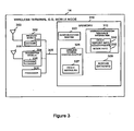
- Figure 3 illustrates an exemplary wireless terminal, e.g., mobile node, implemented in accordance with the present invention.
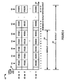
- FIG. 4 is a drawing of exemplary uplink dedicated control channel (DCCH) segments in an exemplary uplink timing and frequency structure in an exemplary orthogonal frequency division multiplexing (OFDM) multiple access wireless communications system.
- DCCH downlink dedicated control channel
- OFDM orthogonal frequency division multiplexing
- Figure 10 is a drawing illustrating an exemplary default mode of the full tone format in a beaconslot for a given DCCH tone.
- Figure 31 is a drawing of a table illustrating an example of mapping between indicator report information bits and the type of report carried by the corresponding flexible report.
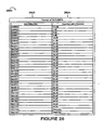
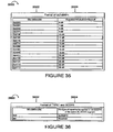
- Figure 34 provides an exemplary summary list of dedicated control reports (DCRs) in the split-tone format for the default mode.
- DCRs dedicated control reports
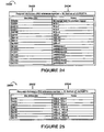
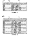
- Figure 36 is an example of mapping between indicator report information bits and the type of report carried by the corresponding flexible report.
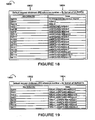
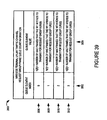
- Figure 38 is a drawing of a table illustrating an exemplary specification of uplink dedicated control channel segment modulation coding in split-tone format.
- Figure 56 is a drawing of an exemplary base station, e.g., access node, implemented in accordance with the present invention and using methods of the present invention.
- Figure 57 is a drawing of an exemplary wireless terminal, e.g., mobile node, implemented in accordance with the present invention and using methods of the present invention.
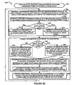
- Figure 60 is a flowchart of an exemplary method of operating a wireless terminal to provide transmission power information to a base station in accordance with the present invention.
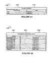
- Figure 62 is an exemplary table used to calculate exemplary control parameters y and z, the control parameters y and z being used in determining uplink multi-bit request reports conveying transmission request group queue information.
- Figure 75 is a drawing used to explain features of an exemplary embodiments of the present invention using a wireless terminal transmission power report.
- most parts referred to as embodiments are not embodiments of this invention in the sense of the claims.
- Each logical tone of the dedicated control channel may be assigned by the base station to a different wireless terminal using the base station as its current point of attachment. For example, logical (tone 0 506, tone 1 508, ... , tone 30 510) may be currently assigned to (WT A 530, WT B 532, ... , WT N' 534), respectively.
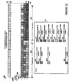
- Figure 7 includes a drawing 700 of an exemplary dedicated control channel in an exemplary uplink timing and frequency structure in an exemplary orthogonal frequency division multiplexing (OFDM) multiple access wireless communications system.
- Drawing 700 may represent the DCCH 400 of Figure 4 , at a time when some of the sets of DCCH segments corresponding to a tone are in the full-tone format and some of the sets of DCCH segments corresponding to a tone are in the split-tone format.
- Vertical axis 702 plots logical tone index of the DCCH while horizontal axis 704 plots the uplink index of the halfslot within a beaconslot.
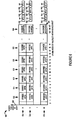
- Figure 8 is a drawing 800 illustrating the use of format and mode in an exemplary uplink DCCH in accordance with the present invention; the mode defining the interpretation of the information bits in the DCCH segments.
- Row 802 corresponding to one tone of the DCCH, illustrates 15 successive segments of the DCCH, in which the split tone-format is used and thus the tone is shared by three wireless terminals, and the mode used by any one of the three WTs can be different.
- row 804 illustrates 15 successive DCCH segments using the full tone format and is used by a single wireless terminal.
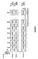
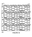
- FIG. 10 is a drawing 1099 illustrating an exemplary default mode of the full tone format in a beaconslot for a given DCCH tone.
- each block (1000, 1001, 1002, 1003, 1004, 1005, 1006, 1007, 1008, 1009, 1010, 1011, 1012, 1013, 1014, 1015, 1016, 1017, 1018, 1019, 1020, 1021, 1022, 1023, 1024, 1025, 1026, 1027, 1028, 1029, 1030, 1031, 1032, 1033, 1034, 1035, 1036, 1037, 1038, 1039) represents one segment whose index s2 (0, ..., 39) is shown above the block in rectangular region 1040.
- the uplink DCCH channel segments switch to the framing format of Figure 10 .
- the point of switching the framing format may or may not be the beginning of a beaconslot.
- there are five DCCH segments for a given DCCH tone for a superslot. For example, suppose that the first uplink superslot is of uplink beaconslot superslot index 2, where beaconslot superslot index range is from 0 to 7.
- the mapping of packets to request groups is done through higher layer protocols. In some exemplary embodiments, there is a default mapping of packets to request groups, that may be changed by the base station and/or WT through higher layer protocols. If the packet belongs to one request group, then, in this exemplary embodiment, all the MAC frames of that packet also belong to that same request group.
- the WT reports the number of MAC frames in the 4 request groups that the WT may intend to transmit. In the ARQ protocol, those MAC frames are marked as "new" or "to be retransmitted”.
- the WT should report the information about N[0:3] to the base station sector so that the base station sector can utilize the information in an uplink scheduling algorithm to determine the assignment of uplink traffic channel segments.
- multiple request dictionaries are supported.
- a request dictionary defines the interpretation of the information bits in uplink traffic channel request reports in the uplink dedicated control channel segments.
- the WT uses one request dictionary.
- the WT uses a default request dictionary.
- the WT and base station sector use an upper layer configuration protocol.
- the wireless terminal first calculates one or more of the following two control parameters y and z, and uses one of the request dictionaries, e.g., Request dictionnary (RD) reference number 0, RD reference number 1, RD reference number 2, RD reference number 3.
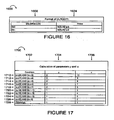
- Table 1700 of Figure 17 is an exemplary table used to calculate control parameters y and z. First column 1702 lists a condition; second column 1704 lists the corresponding value of output control parameter y; third column 1706 lists the corresponding value of output control parameter z.
- First column 2102 identifies the bit pattern and bit ordering, most significant bit to least significant bit.
- Second column 2104 identifies the interpretation associated with each bit pattern.
- An ULRQST3 of table 2100 conveys: (i) information about N[0] and (ii) information about N[2].
- First column 2202 identifies the bit pattern and bit ordering, most significant bit to least significant bit.
- Second column 2204 identifies the interpretation associated with each bit pattern.
- An ULRQST4 of table 2200 conveys one of : (i) no change from the previous 4 bit uplink request, (ii) information about the N[1], and (iii) information about a composite of N[2]+N[3] as a function of either control parameter y or control parameter z of table 1700 of Figure 17 .
- First column 2302 identifies the bit pattern and bit ordering, most significant bit to least significant bit.
- Second column 2304 identifies the interpretation associated with each bit pattern.
- An ULRQST3 of table 2300 conveys: (i) information about N[0] and (ii) information about N[1].
- the methods of the present invention facilitate a wide range of reporting possibilities.
- control parameters e.g., based on SNR and backoff reports
- Table 1800 of Figure 18 For a four bit request where each bit pattern corresponds to a fixed interpretations and does not rely on control parameters, 16 possibilities exists.
- four of the bit patterns (0011, 0100, 0101, and 0110) can each have two different interpretations since control parameter y can have value 1 or 2.
- control parameter z can have any of the values (1, 2, 3, 4, 5, 6, 7, 8, 9, 10). This use of control parameters expands the range of reporting for the 4 bit request report from 16 different possibilities to 111 possibilities.
- each power tier level is associated with a nominal bess power level (e.g., one of bssPowerNominal0, bssPowerNominal1, and bssPowerNominal2) and the pilot channel signal is transmitted at a relative power level with respect to a nominal bss power level for the tone block, e.g., 7.2dB above the nominal bss power level being used by the tone block; however, the beacon per tone relative transmission power level for the BSS is the same irrespective of the tone block from which the beacon is transmitted, e.g., 23.8 dB above the bss power level used by the power tier 0 block (bssPowerNominal0).
- a nominal bess power level e.g., one of bssPowerNominal0, bssPowerNominal1, and bssPowerNominal2
- the pilot channel signal is transmitted at a relative power level with respect to a nominal bss power level for the tone block
- both the generic and the special beacon ratios are determined from the calculated channel gain ratios G1, G2, ..., as follows.
- the WT receives an uplink loading factor sent in a downlink broadcast system subchannel and determines a variable b 0 from uplink loading factor table 2800 of Figure 28 .
- Table 2800 includes a first column 2802 listing eight different values that may be used for the uplink loading factor (0, 1, 2, 3, 4, 5, 6, 7); second column lists the corresponding values for the b value in dB (0, -1, -2, -3, -4, -6, -9, -infinity), respectively.
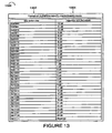
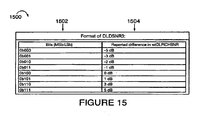
- Figure 29 is a table 2900 illustrating an exemplary format for a 4 bit downlink beacon ratio report (DLBNR4), in accordance with the present invention.
- First column 2902 lists the 16 various bit patterns that the report can convey, while second column 2904 lists the reported power ratio reported corresponding to each bit pattern, e.g., ranging from -3dB to 26dBs.
- the wireless terminal reports the generic and specific beacon ratio reports by selecting and communicating the DLBNR4 table entry that is closed to the determined report value.
- the generic and specific beacon ratio reports use the same table for DLBNR4, in some embodiments, different tables may be used.
- the WT derives the saturation level of the DL SNR, which is defined to be the DL SNR that the WT receiver would measure on a received signal if the BSS transmitted the signal at infinite power, if the base station were capable of transmitting such a signal and the wireless terminal was capable of measuring such a signal.
- the saturation level can be, and in some embodiments is, determined by the self-noise of the WT receiver, which may be caused by factor such as channel estimation errors.
- the following is an exemplary method to derive the saturation level of the DL SNR.
- DL.NCH downlink Null channel
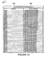
- Table 3000 of Figure 30 is such an exemplary table describing the format of DLSSNR4.
- First column 3002 indicates the 16 different possible bit patterns that can be conveyed by the DLSSNR4 report, and second column 3004 lists saturation levels of DL SNR that are communicated corresponding to each bit pattern ranging from 8.75dB to 29.75 dBs.
- a flexible report is included in the DCCH, such that the WT decides which type of report to communicate and, the type of report can change from one flexible reporting opportunity to the next for a given WT using its allocated dedicated control channel segments.
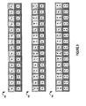
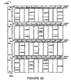
- FIG 32 is a drawing 3299 illustrating an exemplary default mode of the split tone format in a beaconslot for a given DCCH tone for a first WT.
- each block (3200, 3201, 3202, 3203 3204, 3205, 3206, 3207, 3208, 3209, 3210, 3211, 3212, 3213, 3214, 3215, 3216, 3217, 3218, 3219, 3220, 3221, 3222, 3223, 3224, 3225, 3226, 3227, 3228, 3229, 3230, 3231, 3232, 3323, 3234, 3235, 3236, 3237, 3238, 3239) represents one segment whose index s2 (0, ..., 39) is shown above the block in rectangular region 3240.
- the framing format shown in Figure 32 is used repeatedly in every beaconslot, when the default mode of split-tone format is used, with the following exception.
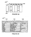
- the WT shall use the framing format shown in Figure 33 .
- the first uplink superslot is defined: for a scenario when the WT migrates to the ON state from the ACCESS state, for a scenario when the WT migrates to the ON state from a HOLD state, and for a scenario when the WT migrates to the ON state from the ON state of another connection.
- Figure 35 is a table 3500 identifying bit format and interpretations associated with each of 16 bit patterns for an exemplary 4 bit uplink transmission backoff report (ULTxBKF4), in accordance with the present invention.
- First column 3502 identifies the bit pattern and bit ordering, most significant bit to least significant bit.
- Second column 3504 identifies the reported WT uplink DCCH Backoff report values in dBs corresponding to each bit pattern each bit pattern. In this exemplary embodiment 16 distinct levels can be reported ranging from 6dB to 36dBs.
- a wireless terminal calculates wtULDCCHBackoff, e.g., as indicated above, selects the closest entry in table 3500 and uses that bit pattern for the report.
- the 4 bit DLBNR4 report follows the same format in the split-tone format default mode as used in the full-tone format default mode.
- the 3 bit ULRQST3 report follows the same format in the split-tone format default mode as used in the full-tone format default mode.
- the 4 bit ULRQST4 report follows the same format in the split-tone format default mode as used in the full-tone format default mode.
- a WT selects the TYPE1 and BODY4 reports by assessing the relative importance if the different types of reports from among which the selection may occur, e.g., the reports listed in table 3600.
- the WT can select the TYPE1 independently from one segment to another.
- b 5 , b 4 , b 3 , b 2 , b 1 , and b 0 denote the information bits to be transmitted in the uplink dedicated control channel segment, where b 5 is the most significant bit and b 0 is the least significant bit.
- c 2 c 1 c 0 (b 5 b 4 b 3 ). ⁇ (b 2 b 1 b 0 ), where . ⁇ is a bit-wise logical OR operation.
- the WT determines a group of seven modulation-symbols from information bit groups b 5 b 4 b 3 according to Table 3700 of Figure 37 .
- the seven modulation-symbols determined from b 7 b 6 b 5 b 4 are to be the seven most significant coded modulation-symbols of the output of the coding and modulation operation.
- Queue 1 information 4004 includes a count of the total number of frames, e.g., MAC frames, of queue 1 traffic (N[1]) that the WT intends to transmit 4020 and the corresponding frames of uplink traffic (frame 1 4022, frame 2, 4024, frame 3 4026, .... frame N 1 4028).
- Queue 2 4006 is the queue for request group 2 information.
- Queue 2 information 4006 includes a count of the total number of frames, e.g., MAC frames, of queue 2 traffic (N[2]) that the WT intends to transmit 4030 and the corresponding frames of uplink traffic (frame 1 4032, frame 2, 4034, frame 3 4036, ..., frame N 2 4038).
- Queue 3 4008 is the queue for request group 3 information.
- Queue 3 information 4008 includes a count of the total number of frames, e.g., MAC frames, of queue 3 traffic (N[3]) that the WT intends to transmit 4040 and the corresponding frames of uplink traffic (frame 1 4042, frame 2, 4044, frame 3 4046, ..., frame N 3 4048).
- the request queues, for at least some wireless terminals are priority queues.
- Drawing 4017 of Figure 73 illustrates exemplary mapping for a WT C at a second time T2, of uplink data stream traffic flows to its request group queues.
- First column 4019 includes information type of the data stream traffic flow;
- second column 4021 includes the identified queue (request group);
- third column 4023 includes comments.
- First row 4025 indicates that control information is mapped to request group 0 queue. Flows mapped to the request group 0 queue are considered high priority, have strict latency requirements, require low latency and/or have low bandwidth requirements.
- Second row 4027 indicates that voice application and a gaming application is mapped to request group 1 queue. Flows mapped to the request group 1 queue also require low latency but have a lower priority level than request group 0.
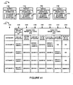
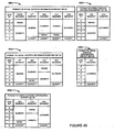
- Figure 41 illustrates an exemplary request group queue structure, multiple request dictionaries, a plurality of types of uplink traffic channel request reports, and grouping of sets of queues in accordance with exemplary formats used for each of the types of reports.
- the exemplary structure accommodates four request dictionaries.
- the exemplary structure uses three types of uplink traffic channel request reports (a 1 bit report, a 3-bit report, and a 4-bit report).
- Table 4118 identifies grouping of queue sets used by different types of request reports as a function of the dictionary in use.
- Column 4120 identifies the dictionary.
- the first type of exemplary report is, e.g., a 1 bit information report.
- Column 4122 identifies the first set of queues used for first type reports.
- the first set of queues is the set ⁇ queue 0 and queue 1 ⁇ for the first type of report irrespective of the request dictionary.
- Column 4124 identifies the second set of queues used for second type reports.
- the second set of queues is the set ⁇ queue 0 ⁇ for the second type of report irrespective of the request dictionary.
- Column 4126 identifies the third set of queues used for second type reports.
- the third set of queues is: (i) the set ⁇ queue 1, queue 2, queue 3 ⁇ for the second type of report for request dictionary 0, (ii) the set of ⁇ queue 2 ⁇ for the second type of report for request dictionary 1, and (iii) the set of ⁇ queue 1 ⁇ for the second type of report for dictionary 2 and 3.
- the third type of report uses a fourth and fifth set of queues for each dictionary.
- the third type of report uses a sixth set of queues for dictionaries 1, 2, and 3.
- the third type of report uses a seventh set of queues for dictionary 3. Column 4128 identifies that the fourth set of queues for the third type of report is the set ⁇ queue 0 ⁇ irrespective of the dictionary.
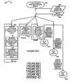
- Figures 42 comprising the combination of Figure 42A , Figure 42B , Figure 42C , Figure 42D , and Figure 42E is a flowchart 4200 of an exemplary method of operating a wireless terminal in accordance with the present invention.
- Operation of the exemplary method starts in step 4202, where the WT is powered on and initialized.
- Queue definition information 4204 e.g., mapping information defining mapping of traffic flows from various applications into MAC frames of specific request group queues and various grouping of request groups into sets of request groups, and sets of request dictionary information 4206 are available for use by the wireless terminal.
- the information 4204 and 4206 may be pre-stored in the wireless terminal in non-volatile memory.
- a default request dictionary from among the plurality of available request dictionaries is used by the wireless terminal initially, e.g., request dictionary 0. Operation proceeds from start step 4202 to steps 4208, 4210 and 4212.
- step 4208 the wireless terminal maintains transmission queue stats for a plurality of queues, e.g., request group 0 queue, request group 1 queue, request group 2 queue and request group 3 queue.
- Step 4208 includes sub-step 4214 and sub-step 4216.
- the wireless terminal increments queue stats when data to be transmitted is added to a queue. For example, new packets from an uplink data stream flow, e.g., a voice communications session flow, are mapped as MAC frames to one of the request groups, e.g., request group 1 queue and a queue stat, e.g., N[1] representing the total number of request group 1 frames that the WT intends to transmit is updated.
- different wireless terminals use different mappings.
- the WT decrements the queue stats when data to be transmitted is removed from a queue. For example, the data to be transmitted may be removed from the queue because the data has been transmitted, the data has been transmitted and a positive acknowledgement was received, the data no longer needs to be transmitted because a data validity timer has expired, or the data no longer needs to be transmitted because the communications session has been terminated.
- the wireless terminal In step 4210, the wireless terminal generates transmission power availability information. For example, the wireless terminals calculates the wireless terminal transmission backoff power, determines a wireless terminal transmission backoff power report value, and stores backoff power information. Step 4210 is performed on an ongoing basis with the stored information being updated, e.g., in accordance with a DCCH structure.
- the wireless terminal In step 4212, the wireless terminal generates transmission path loss information for at least two physical attachment points. For example, the wireless terminal measures received pilot and/or beacon signals from at least two physical attachment points calculates a ratio value, determines a beacon ratio report value, e.g., corresponding to a generic beacon ratio report of a first or second type or a specific beacon ratio report, and stores the beacon ratio report information. Step 4212 is performed on an ongoing basis with the stored information being updated, e.g. in accordance with a DCCH structure.
- each reporting opportunity in a (first, second, third) set of predetermined transmission queue stats reporting opportunities operation goes to (sub-routine 1 4224, sub-routine 2 4238, subroutine 3 4256), via (step 4218, step 4220, step 4222), respectively.
- each first set of predetermined transmission queue stat reporting opportunities corresponds to each one-bit uplink traffic channel request reporting opportunity in the timing structure. For example, if a WT is communicating over DCCH segments using the full-tone DCCH format default mode, e.g., of Figure 10 , the WT receives 16 opportunities to send ULRQST1 in a beaconslot.
- each second set of predetermined transmission queue stat reporting opportunities corresponds to each three-bit uplink traffic channel request reporting opportunity in the timing structure. For example, if a WT is communicating over DCCH segments using the full-tone DCCH format default mode, e.g., of Figure 10 , the WT receives 12 opportunities to send ULRQST3 in a beaconslot. If a WT is communicating over DCCH segments using the split-tone DCCH format default mode, e.g., of Figure 32 , the WT receives 6 opportunities to send ULRQST3 in a beaconslot.
- each third set of predetermined transmission queue stat reporting opportunities corresponds to each four-bit uplink traffic channel request reporting opportunity in the timing structure.
- step 4226 the WT receives backlog information for a first set of queues, e.g. the set of ⁇ Queue 0, Queue 1 ⁇ where the information received is N[0] + N[1]. Operation proceeds from step 4226 to step 4230.
- a first set of queues e.g. the set of ⁇ Queue 0, Queue 1 ⁇ where the information received is N[0] + N[1]. Operation proceeds from step 4226 to step 4230.
- step 4230 the WT transmits a first number of information bits, e.g., 1 information bit, indicating a traffic backlog in the first set of queues, e.g. the information bit is set equal to 1. Operation proceeds from either step 4232 or step 4234 to return step 4236.
- step 4240 the WT receives backlog information for a second set of queues, e.g. the set of ⁇ Queue 0 ⁇ where the information received is N[0].
- step 4240 the WT also receives backlog information for a third set of queues, e.g., the set ⁇ queue 1, queue2, queue3 ⁇ or ⁇ queue 2 ⁇ or ⁇ queue 1 ⁇ depending on the request dictionary in use by the WT. For example, corresponding to dictionary (1, 2, 3, 4), the WT may receive (N[1] + N[2] + R1[3], N[2], N[1], N[1]), respectively. Operation proceeds from step 4240 to step 4246.
- step 4246 the WT jointly encodes the backlog information corresponding to the second and third sets of queues into a second predetermined number of information bits, e.g., 3, said joint encoding optionally including quantization.
- sub-step 4248 and sub-step 4250 are performed as part of step 4246.
- sub-step 4248 and sub-step 4250 are performed as part of step 4246.
- Sub-step 4248 directs operation to a quantization level control factor subroutine.
- Sub-step 4250 calculates a quantization level as a function of a determined control factor.
- each of the quantization levels are calculated as a function of control factory.
- sub-steps 4248 and 4250 are performed in determining the information bit pattern to place in the ULRQST3 report.
- request dictionary 1 as shown in Figure 21 .
- none of the quantization levels are calculated as a function of a control factor, e.g. y or z, and therefore sub-step 4248 and 4250 are not performed.
- Exemplary traffic availability subroutine 3 4256 will now be described. Operation starts in step 4258, and the WT receives backlog information for a fourth set of queues, e.g. the set of ⁇ Queue 0 ⁇ where the information received is N[0].
- the WT also receives backlog information for a fifth set of queues, e.g., the set ⁇ queue 1, queue2, queue3 ⁇ or ⁇ queue 2 ⁇ or ⁇ queue 1 ⁇ depending on the request dictionary in use by the WT. For example, corresponding to dictionary (0, 1, 2, 3), the WT may receive (N[1] + R1[2] + N[3], N[2], N[1], N[1]), respectively.
- the WT may also receives backlog information for a sixth set of queues, e.g., the set ⁇ queue 1, queue3 ⁇ or ⁇ queue 2, queue3 ⁇ or ⁇ queue 2 ⁇ depending on the request dictionary in use by the WT. For example, corresponding to dictionary (1, 2, 3), the WT may receive (N[1] + N[3], N[2] + N[3], N[2]), respectively.
- the WT may also receive backlog information for a seventh set of queues, e.g., the set ⁇ queue 3 ⁇ if request dictionary 3 is in use by the WT. Operation proceeds from step 4258 to step 4266.
- step 4268 Operation proceeds from step 4268 to step 4274, where the WT transmits the coded backlog information for one of the fourth, fifth, sixth, and seventh sets of queues using the third predetermined number of information bits, e.g., 4 information bits. Operation proceeds from step 4274 to return step 4276.
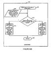
- FIG 43 is a flowchart 4300 of an exemplary method of operating a wireless terminal in accordance with the present invention. Operation starts in step 4302, where the wireless terminal is powered on, initialized, has established a connection with a base station. Operation proceeds from start step 4302 to step 4304.
- step 4306 the WT determines a set of 21 coded modulation-symbol values from 6 information bits (b5, b4, b3, b2, b1, b0).
- Step 4306 includes sub-steps 4312, 4314, 4316, and 4318.
- step 4310 the wireless terminal transmits the twenty-one determined modulation symbols of the segment.
- each DCCH segment corresponds to 21 OFDM tone symbols each tone-symbol of the DCCH segment using the same single logical tony in the plink timing and frequency structure.
- the logical tone may be hopped during a DCCH segment, e.g., the same logical tone may corresponds to three different physical tones in the uplink tone block being used for the connection, with each physical tone remaining the same for seven successive OFDM symbol transmission time periods.
- FIG. 44 is a flowchart 4400 of an exemplary method of operating a wireless terminal to report control information in accordance with the present invention. Operation starts in step 4402, where the wireless terminal is powered up and initialized. Operation proceeds from start step 4402 to step 4404. In step 4404, the WT checks as to whether or not one of the following has occurred: (i) a transition from a first mode of WT operation to a second mode of WT operation and (ii) a handoff operation from a first connection to a second connection while remaining in the second mode of operation.
- the second mode of operation is an ON mode of operation and said first mode of operation is one of a hold mode of operation, a sleep mode of operation, and an ACCESS mode of operation.
- step 4406 the WT transmits an initial control information report set, said transmission of the initial control information report set having a first duration equal to a first time period.
- the initial control information report set can include one or a plurality of reports. Operation proceeds from step 4406 to step 4408.
- step 4408 the WT checks as to whether or not the WT is in the 2 nd mode of operation. If the WT is in the second mode of operation, operation proceeds from step 4408 to step 4410; otherwise operation proceeds to step 4404.
- Figures 45 and 46 are used to illustrate an exemplary embodiment of the present invention. Figures 45 and 46 are applicable to some embodiments discussed with respect to flowchart 4400 of Figure 44 .
- Drawing 4500 of Figure 45 includes a initial control information report set 4502, followed by a first additional control information report set 4504, followed by a second additional control information report set 4506, followed by a 2 nd iteration of first additional control information report set 4508, followed by a 2 nd iteration of second additional control information 4510.
- Each control information report set (4502, 4504, 4506, 4508, 4510) has a corresponding transmission time period (4512, 4514, 4516, 4518, 4520), respectively, where the duration of each of the time periods (4512, 4514, 4516, 4518, 4520) is the same, the duration being 105 OFDM symbol transmission time periods.
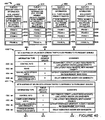
- Drawing 4630 describes the format of an exemplary 1 st additional control information report set.
- First column 4632 identifies the bit definition (5, 4, 3, 2, 1, 0).
- Second column 4634 identifies the first segment includes a DLSNR5 report and a ULRQST1 report.
- Third column 4636 identifies that the second segment includes a RSVD2 report and an ULRQST4 report.
- Fourth column 4638 identifies that the third segment includes a DLDSNR3 report and an ULRQST3 report.
- Fifth column 4640 identifies that the fourth segment includes a DLSNR5 report and a ULRQST1 report.
- Sixth column 4642 identifies that the sixth segment includes an RSVD2 report and an ULRQST4 report.
- the initial and first additional reports sets will be different because they use different formats.
- the initial control information report set includes at least two reports, DLBNR4 and ULTXBKF5, that are not included in the first additional control information report set.
- the DLBNR4 is an interference report and the ULTXBKF5 is a wireless terminal power availability report.
- the second additional report includes at least one additional report that is not included in the first additional report, RSVD1 report.
- step 4704 the communications device checks as to whether or at least one of the following has occurred: (i) a transition from a first mode of communications device operation to a second mode of communications device operation and (ii) a handoff operation from a first connection, e.g., with a first base station sector physical attachment point, to a second connection, e.g., with a second base station sector physical attachment point, while remaining in the second mode of communications device operation.
- the second mode of communications device operation is an ON mode of operation
- the first mode of operation is one of a hold mode of operation and a sleep mode of operation.
- the communications device can transmit user data on an uplink during the ON mode of operation and is precluded from transmitting user data on the uplink during the hold and sleep modes of operation.
- step 4704 If at least one of the tested conditions of step 4704 was satisfied, then operation proceeds from step 4704 to either step 4706 or step 4708 depending upon the embodiment.
- Step 4706 is an optional step included in some embodiments, but omitted in other embodiments.
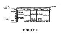
- the communications device uses the initial report set as indicated in Table 1199 of Figure 11 for the first superslot, and then uses the predetermined sequence of table 1099 of Figure 10 for subsequent superslots while remaining in the ON state.
- the initial report set can replace any of the sets corresponding to segment index grouping (0-4), (5-9), (10-14), (15-19), (20-24), (25-29), (30-34, (35-39), depending upon when the state transition to the ON mode of operation occurs.
- the format of initial control information report set #2 4850 is used; otherwise the format of initial control information report set #1 is used.
- the 4 bit downlink beacon ratio report, DLBNR4 only occurs once during a beaconslot, and it occurs in the 4 th superslot of the beaconslot.
- initial control information report set #2 4910 is used.
- initial control information report set #3 4920 is used.
- initial control information report set #4 4930 is used.
- initial control information report set #5 4940 is used.
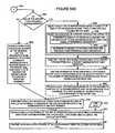
- each of the dedicated control channel segments includes the same number of tone-symbols, e.g., 21 tone-symbols. Operation proceeds from start step 5002 to step 5004.
- Two exemplary types of embodiments are illustrated in flowchart 5000.
- the base station sends mode control signals to command changes between first and second modes of operation. In such exemplary embodiments, operation proceeds from step 5002 to steps 5010 and 5020.
- the wireless terminal requests mode transitions between first and second modes. In such an embodiments, operation proceeds from step 5002 to steps 5026 and step 5034.
- Embodiments are also possible, in accordance with the present invention, where the base station can command mode changes without input from the wireless terminal, and where the wireless terminal can request mode changes, e.g., with the base station and wireless terminal each being capable of initiating a mode change.
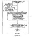
- step 5004 the WT checks as to whether the WT is currently in a first or second mode of operation. If the WT is currently in a first mode of operation, e.g., a full tone mode, operation proceeds from step 5004 to step 5006. In step 5006, the WT uses a first set of dedicated control channel segments during a first period of time, said first set including a first number of dedicated control channel segments. However, if it is determined in step 5004, that the WT is in a second mode of operation, e.g., a split tone mode, operation proceeds from step 5004 to step 5008. In step 5008, the WT uses a second set of dedicated control channel segments during a second period of time having the same duration of as said first time period, said second set of control channel segments including fewer segments than said first number of segments.
- a first mode of operation e.g., a full tone mode
- step 5006 the WT uses a first set of dedicated control channel segments during a first period of time, said first set including a first number of dedicated
- the first set in the full-tone mode includes 40 DCCH segments using a single logical tone
- the second set in the split-tone mode includes 13 DCCH segments using a single logical tone.
- the single logical tone used by the WT in the full-mode may be same or different than the single logical tone used in the split tone mode.
- the first set in full-tone mode includes 39 DCCH segments using a single logical tone
- the second set in the split-tone mode includes 13 DCCH segments using a single logical tone.
- the first number of segments divided by the second number of segments is the integer 3.
- the single logical tone used by the WT in the full-mode may be same or different than the single logical tone used in the split tone mode.
- the second set of dedicated control channel segments used by the WT is, iri some embodiments, a subset of a larger set of dedicated control channel segments that can be used by the same or a different WT in a full-tone mode of operation during a time period that is not the second time period.
- the first set of dedicated control channel segments used during the first period of time by the wireless terminal can be the larger set of dedicated control channel segments, and the first and second sets of dedicated control channel segments can correspond to the same logical tone.
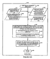
- step 5002 Operation proceeds from step 5002 to step 5010 for each 1 st type of mode control signal directed to the WT, e.g., a mode control signal commanding the WT to switch from a first mode to a second mode of operation.
- the WT receives a first type mode control signal from a base station.
- step 5012 the WT checks as to whether or not it is currently in a first mode of operation. If the wireless terminal is in a first mode of operation, operation proceeds to step 5014 where the WT switches from a first mode of operation to a second mode of operation in response to said received control signal.
- step 5012 determines whether the WT is currently in the first mode of operation. If it is determined in step 5012 that the WT is not currently in the first mode of operation, the WT proceeds via connecting node A 5016 to step 5018, where the WT stops the implementation of the mode change since there is a misunderstanding between the base station and WT.
- step 5022 determines whether the WT is currently in the second mode of operation. If it is determined in step 5022 that the WT is not currently in the second mode of operation, the WT proceeds via connecting node A 5016 to step 5018, where the WT stops the implementation of the mode change since there is a misunderstanding between the base station and WT.
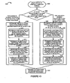
- Operation proceeds from step 5002 to step 5026 for each time that the wireless terminal proceeds to initiate a mode change from a first mode of operation, e.g., full-tone DCCH mode, to a second mode of operation, e.g., split-tone DCCH mode.
- the WT transmits a mode control signal to a base station.
- the WT receives an acknowledgement signal from the base station.
- Operation proceeds from step 5028 to step 5030.
- step 5030 if the received acknowledgement signal is a positive acknowledgment, operation proceeds to step 5032, where the wireless terminal switches from a first mode of operation to a second mode of operation in response to said received positive acknowledgement signal.
- the WT determines that the received signal is a negative acknowledgment signal or the WT cannot successfully decode the received signal the WT proceeds via connecting node A 5016 to step 5018 where the WT stops the mode change operation.
- Operation proceeds from step 5002 to step 5034 for each time that the wireless terminal proceeds to initiate a mode change from a second mode of operation, e.g., split-tone DCCH mode, to a first mode of operation, e.g., full-tone DCCH mode.
- the WT transmits a mode control signal to a base station.
- step 5034 the WT receives an acknowledgement signal from the base station.
- step 5036 the WT receives an acknowledgement signal from the base station.
- step 5038 if the received acknowledgement signal is a positive acknowledgment, operation proceeds to step 5040, where the wireless terminal switches from a second mode of operation to a first mode of operation in response to said received positive acknowledgement signal.
- the WT determines that the received signal is a negative acknowledgment signal or the WT cannot successfully decode the received signal the WT proceeds via connecting node A 5016 to step 5018 where the WT stops the mode change operation.
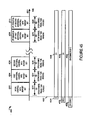
- Figure 51 is a drawing illustrating exemplary operation in accordance with the present invention.
- the dedicated control channel is structured to use a repeating pattern of 16 segments indexed from 0 to 15, for each logical tone in the dedicated control channel.
- Other embodiments, in accordance with the present invention may use a different number of indexed DCCH segments in a recurring pattern, e.g., 40 segments.
- Four exemplary logical DCCH tones, indexed (0, 1, 2, 3) are illustrated in Figure 51 .
- each segment occupies the same amount of air link resources.
- each segment has same number of tone-symbols, e.g., 21 tone-symbols.
- Drawing 5100 identifies the index of the segments over time for two successive iterations of the pattern corresponding to a logical tone in drawing 5104.
- WT1 is in full-tone DCCH mode during the first time period 5110 and uses a set of 15 segments (indexed 0-14) corresponding to logical tone 0 during that time period.
- WT1 is in split-tone DCCH mode and uses a set of 5 segments with index values (0, 3, 6, 9, 12) corresponding to logical tone 0, which is a subset of the set of segments used during the 1 st time period 5110.
- WT4 is in full-tone DCCH mode during 1 st time period 5110 and uses a set of 15 segments (indexed 0-14) corresponding to logical tone 2, and WT4 is in split tone format during 2 nd time period 5112 and uses a set of 5 segments with index values (1, 4. 7, 10, 13) corresponding to logical tone 3. It should also be observed that the set of 5 segments with index values (1, 4, 7, 10, 13) corresponding to logical tone 3 is part of a larger set of segments used by WT6 in full-tone DCCH mode during the 1 st time period 5110.
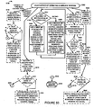
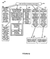
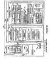
- FIG 52 is a flowchart 5200 of an exemplary method of operating a base station in accordance with the present invention. Operation of the exemplary method starts in step 5202, where the base station is powered on and initialized. Operation proceeds to steps 5204 and steps 5206.
- step 5204 the base station, on an ongoing basis, partitions the dedicated control channel resources between full-tone DCCH sub-channels and split tone DCCH sub-channel and allocates the full-tone and split tone DCCH sub-channels among a plurality of wireless terminals.
- the DCCH channel uses 31 logical tones and each logical tone corresponds to 40 DCCH channel segments in a single iteration of a repeating pattern, e.g., on a beaconslot basis.
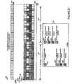
- Figure 53 illustrates exemplary partitioning and allocation of dedicated control channel resources for another exemplary embodiment, e.g., an embodiment using 16 indexed DCCH segments corresponding to a logical tone which repeat on a recurring basis.
- the method described with respect to Figure 53 may be used in step 5204 and may be extended to other embodiments.
- Step 5204 includes sub-step 5216, in which the base station communicates to the WTs sub-channel allocation information.
- Sub-step 5216 includes sub-step 5218.
- the base station assigns user identifiers to WTs receiving allocation of dedicated control channel segments, e.g., On state user identifiers.
- the base station receives uplink signals from WTs including dedicated control channel reports communicated on the allocated DCCH sub-channels.
- the wireless terminals use different coding to communicate information transmitted in DCCH segments during a full-tone DCCH mode of operation and during a split-tone DCCH mode of operation; therefore the base station performs different decoding operations based on the mode.
- the base station sends mode control signals to command changes between first and second modes of operation, e.g., between full-tone DCCH mode and split-tone DCCH mode. In such exemplary embodiments, operation proceeds from step 5202 to steps 5208 and 5010.
- the wireless terminal requests mode transitions between first and second modes, e.g., between full-tone DCCH mode and split-tone DCCH mode. In such an embodiment, operation proceeds from step 5202 to steps 5212 and step 5214.
- Embodiments are also possible, in accordance with the present invention, where the base station can command mode changes without input from the wireless terminal, and where the wireless terminal can request mode changes, e.g., with the base station and wireless terminal each being capable of initiating a mode change.
- step 5210 Operation proceeds to step 5210 for each instance where the base station decides to command a WT to change from the second mode, e.g., split-mode DCCH mode, to the first mode, e.g. full-tone DCCH mode.
- the base station sends a mode control signal to a WT to initiate a WT transition from the second mode, e.g., split-tone DCCH mode, to the first mode, e.g., full-tone DCCH mode.
- step 5212 Operation proceeds to step 5212 for each instance where the base station receives a request from a WT to change from a first mode, e.g., full-tone DCCH mode to a second mode, e.g. split-tone DCCH mode.
- the base station receives a mode control signal from a WT requesting a transition from a first mode of operation to a second mode of operation, e.g., from full-tone DCCH mode to split-tone DCCH mode.
- step 5220 if the base station decides to accommodate the request.
- the base station transmits a positive acknowledgement signal to the WT which sent the request.
- step 5214 Operation proceeds to step 5214 for each instance where the base station receives a request from a WT to change from a second mode, e.g., split-tone DCCH mode to a first mode, e.g. full-tone DCCH mode.
- the base station receives a mode control signal from a WT requesting a transition from a second mode of operation to a first mode of operation, e.g., from split-tone DCCH mode to full-tone DCCH mode.
- step 5222 if the base station decides to accommodate the request.
- the base station transmits a positive acknowledgement signal to the WT which sent the request.
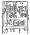
- Drawing 5304 plots logical DCCH tone index on vertical axis 5306 vs time on horizontal axis 5308.
- a first time period 5310 and a second time period 5312 are shown which have the same duration.
- Legend 5314 identifies: (i) squares with widely spaced crosshatch shading 5316 represents WT1 full-tone DCCH mode segments, (ii) squares with narrowly spaced crosshatch shading 5318 represents WT2 full-tone DCCH mode segments, (iii) squares with widely spaced vertical and horizontal line shading 5320 represent WT4 full-tone DCCH mode segments, (iv) squares with narrowly spaced vertical and horizontal line shading 5322 represent WT9 full-tone DCCH mode segments, (v) squares with widely spaced diagonal line shading sloping upward from left to right 5324 represent WT1 split-tone DCCH mode segments (vi) squares with narrowly spaced diagonal line shading sloping downward from left to right 5326 represent WT2 split-tone DCCH mode segments, (vii) squares with
- WT1 is in full-tone DCCH mode during the first time period 5310 and uses a set of 15 segments (indexed 0-14) corresponding to logical tone 0 during that time period.
- a base station allocated a first dedicated control sub-channel to WT1, the first dedicated control sub-channel including the set of 15 segments (indexed 0-14) corresponding to logical tone 0 for use during 1 st time period 5310.
- WT2, WT3, and WT4 are each split-tone DCCH mode during the first time period 5310 and each use a set of 5 segments indexed ((0, 3, 6, 9, 12), (1, 4, 7, 10, 13); (2, 5, 8, 11, 14)), respectively corresponding to the same logical tone, logical tone 1 during 1 st time period 5310.
- a base station allocated a (second, third, and fourth) dedicated control sub-channel to (WT2, WT3, WT3), the (second, third, and fourth) dedicated control sub-channels each including a set of 5 segments with index values.((0, 3, 6, 9, 12), (1, 4, 7, 10, 13), (2, 5, 8, 11, 14)), respectively corresponding to the same logical tone, logical tone 1 during 1st time period 5310.
- WT6, WT7, and WT8 are each split-tone DCCH mode during the first time period 5310 and each use a set of 5 segments indexed ((0, 3, 6, 9, 12), (1, 4, 7, 10, 13), (2, 5, 8, 11, 14)), respectively corresponding to the same logical tone, logical tone 2 during 1st time period 5310.
- a base station allocated a (fifth, sixth, and seventh) dedicated control sub-channel to (WT6, WT7, WT8), the (fifth, sixth, and seventh) dedicated control sub-channels each including a set of 5 segments with index values ((0, 3, 6, 9, 12), (1, 4, 7, 10,13). (2, 5, 8, 11, 14)), respectively corresponding to the same logical tone, logical tone 2 during 1 st time period 5310.
- (WT2) is in full-tone DCCH mode during the second time period 5312 and uses a set of 15 segments indexed (0-14) corresponding to logical tone 1 during the second time period 5312.
- a base station allocated a (tenth) dedicated control sub-channel to (WT2), the dedicated control sub-channel including the set of 15 segments indexed (0-14) corresponding to logical tone 1 during the second time period 5312.
- WT2 is one of the WTs from the set of (WT2, WT3, WT4) which used logical tone 1 during the first time period 5310.
- (WT9) is in full-tone DCCH mode during the second time period 5312 and each uses a set of 15 segments indexed (0-14) corresponding to logical tone 2 during the second time period 5312.
- a base station allocated an (eleventh) dedicated control sub-channel to (WT9), the dedicated control sub-channel including the set of 15 segments indexed (0-14) corresponding to logical tone 2 during the second time period 5312.
- WT9 is a different WT than the WTs (WT6, WT7, WT8) which used logical tone 2 during the first time period 5310.
- the logical tones (tone 0, tone 1, tone 2) are subjected to an uplink tone hopping operation which determines which physical tones the logical tones correspond to for each of a plurality of symbol transmission time periods, e.g., in the first time period 5310.
- logical tones 0, 1, and 2 may be part of a logical channel structure including 113 logical tones, which are hopped, in accordance with a hopping sequence to a set of 113 physical tones used for uplink signaling.
- each DCCH segment corresponds to a single logical tone and corresponds to 21 successive OFDM symbol transmission time intervals.
- the logical tone is hopped such that the logical tone corresponding to three physical tones, with the wireless terminal using each physical tone for seven consecutive symbol transmission time intervals of the segment.
- an exemplary 1 st and 2 nd time period may each include 39 DCCH segments, e.g., the first 39 DCCH segments of a beaconslot corresponding to the logical tone.
- a WT is allocated by the base station a set of 39 DCCH segments for the 1 st or 2 nd time period corresponding to the allocation.
- a WT is allocated a set of 13 DCCH segments for the 1 st or 2 nd time period corresponding to the allocation.
- the 40 th indexed segment can also be allocated to and used by the WT in full-tone mode.
- the 40 th indexed segment is a reserved segment.
- FIG. 54 is a drawing of a flowchart 5400 of an exemplary method of operating a wireless terminal in accordance with the present invention. Operation starts in step 5402 where the wireless terminal is powered on and initialized. Operation proceeds from step 5402 to steps 5404, 5406, and 5408.
- the wireless terminal measures the received power of a downlink null channel (DL.NCH) and determines an interference power (N).
- DL.NCH downlink null channel
- N interference power
- the Null channel corresponds to predetermined tone-symbols in an exemplary downlink timing and frequency structure used by the base station serving as the current attachment point for the wireless terminal in which the base station intentionally does not transmit using those tone-symbols; therefore, received power on the NULL channel measured by the wireless terminal receiver represents interference.
- step 5406 the wireless terminal measures the received power (G*P 0 ) of a downlink pilot channel (DL.PICH).
- step 5408 the wireless terminal measures the signal to noise ratio (SNR 0 ) of the downlink pilot channel (DL.PICH). Operation proceeds from steps 5404, 5406, and 5408 to step 5410.
- step 5412 the wireless terminal selects the closest value from a predetermined table of quantized level of saturation level of downlink SNR to represent the calculated saturation level in a dedicated control channel report, and the wireless terminal generates the report. Operation proceeds from step 5412 to step 5414.
- the wireless terminal transmits the generated report to the base station, said generated report being communicated using a dedicated control channel segment allocated to the wireless terminal, e.g., using a predetermined portion of a predetermined indexed dedicated control channel segment.
- FIG 55 is a drawing of an exemplary wireless terminal 5500, e.g., mobile node, implemented in accordance with the present invention and using methods of the present invention.
- Exemplary WT 5500 may be any of the wireless terminals of the exemplary system of Figure 1 .
- Exemplary wireless terminal 5500 includes a receiver module 5502, a transmitter module 5504, a processor 5506, user I/O devices 5508, and a memory 5510 coupled together via a bus 5512 over which the wireless terminal 5500 interchanges data and information.
- the receiver module 5502 e.g., an OFDM receiver, is coupled to a receive antenna 5503 via which the wireless terminal 5500 receives downlink signals from base stations.
- Downlink signals received by the wireless terminal 5500 include: mode control signals, mode control request response signals, assignment signals including the assignment of user identifiers, e.g., an ON identifier associated with a logical uplink dedicated control channel tone, uplink and/or downlink traffic channel assignment signals, downlink traffic channel signals, and downlink base station identification signals.
- Receiver module 5502 includes a decoder 5518 via which the wireless terminal 5500 decodes received signals which had been encoded prior to transmission by the base station.
- the transmitter module 5504 is coupled to a transmit antenna 5505 via which the wireless terminal 5500 transmits uplink signals to base stations.
- Uplink signals transmitted by the wirelessed include: mode requests signals, access signals, dedicated control channel segment signals during first and second modes of operation, and uplink traffic channel signals.
- Transmitter module 5504 includes an encoder 5520 via which the wireless terminal 5500 encodes at least some uplink signals prior to transmission.
- Encoder 5520 includes a 1 st coding module 5522 and a 2 nd Coding module 5524.
- 1 st coding module 5522 codes information to be transmitted in DCCH segments during the first mode of operation according to a first coding method.
- 2 nd coding module 5524 codes information to be transmitted in DCCH segments during the second mode of operation according to a second coding method; the first and second coding methods are different.
- User I/O devices 5508 e.g., microphone, keyboard, keypad, mouse, switches, camera, display, speaker, etc., are used to input data/information, output data/information, and control at least some functions of the wireless terminal, e.g., initiate a communications session.
- Memory 5510 includes routines 5526 and data/information 5528.
- the processor 5506 e.g., a CPU, executes the routines 5526 and uses the data/information 5528 in memory 5510 to control the operation of the wireless terminal 5500 and implement methods of the present invention.
- Routines 5526 include a communications routine 5530 and wireless terminal control routines 5532.
- the communications routine 5530 implements the various communications protocols used by the wireless terminal 5500.
- the wireless terminal control routines 5532 control operation of the wireless terminal 5500 including controlling operation of the receiver module 5502, transmitter module 5504 and user I/O devices 5508.
- Wireless terminal control routines 5532 include a first mode dedicated control channel communications module 5534, a second mode dedicated control channel communications module 5536, a dedicated control channel mode control module 5538, a mode request signal generation module 5540, a response detection module 5542, and an uplink dedicated control channel tone determination module 5543.
- the first mode dedicated control channel communications module 5534 controls dedicated control channel communications using a first set of dedicated control channel segments during a first mode of operation, said first set including a first number of control channel segments for a first period of time.
- the first mode is, in some embodiments, a full tone mode, of dedicated control channel operation.
- the second mode dedicated control channel communications module 5536 controls dedicated control channel communications using a second set of dedicated control channel segments during a second mode of operation, said second set of dedidated control channel segments corresponding to a time period having the same duration as said first period of time, said second set of dedicated control channel segments including fewer segments than said first number of dedicated control channel segments.
- the second mode is, in some embodiments, a split-tone mode, of dedicated control channel operation.
- a dedicated control channel segment whether in the first mode or the second mode of operation uses the same amount of uplink air link resources, e.g., the same number of tone-symbols, e.g., 21 tone-symbols.
- a dedicated control channel segment may correspond to one logical tone in the timing and frequency structure being used by the base station, but may correspond to three physical tones with three sets of seven tone-symbols each being associated with a different physical uplink tone in accordance with uplink tone hopping information.
- DCCH mode control module 5538 controls switching into a requested mode of operation which is one of the first mode of operation, e.g., full-tone DCCH mode, and the second mode of operation, e.g., split-tone DCCH mode, in response to a received affirmative request acknowledgment signal.
- a requested mode of operation which is one of the first mode of operation, e.g., full-tone DCCH mode, and the second mode of operation, e.g., split-tone DCCH mode
- Uplink DCCH tone determination module 5543 determines the physical tone to which an assigned logical DCCH tone corresponds to over time based on the uplink tone hopping information stored in the wireless terminal.
- Data/information 5528 includes user/device/session/resource information 5544, system data/information 5546, current mode of operation information 5548, terminal ID information 5550, DCCH logical tone information 5552, mode request signal information 5554, timing information 5556, base station identification information 5558, data 5560, DCCH segment signal information 5562, and mode request response signal information 5564.
- User/device/session/resource information 5544 includes information corresponding to peer nodes in communications sessions with WT 5500, address information, routing information, session information including authentication information, and resource information including allocated DCCH segments and uplink and/or downlink traffic channel segments associated with the communications session which are allocated to WT 5500.
- Current mode of operation information 5548 includes information identifying whether the wireless terminal is currently in a first, e.g., full-tone DCCH mode of operation, or a second, e.g., split-tone DCCH mode of operation. In some embodiments, the first and second modes of operation with respect to the DCCH both correspond to wireless terminal On states of operation. Current mode of operation information 5548 also includes information identifying other modes of wireless terminal operation, e.g., sleep, hold, etc. Terminal identifier information 5550 includes base station assigned wireless terminal identifiers, e.g., registered user identifier and/or an ON state identifier.
- the ON state identifier is associated with a DCCH logical tone being used by the base station sector attachment point which allocated the On state identifier to the wireless terminal.
- DCCH logical tone information 5552 includes, when the wireless terminal is in one of first mode of DCCH operation and a second mode of DCCH operation, information identifying the DCCH logical tone currently allocated to the wireless terminal to use when communicating uplink DCCH segment signals.
- Timing information 5556 includes information identifying the wireless terminals current timing within the repetitive timing structure being used by the base stations serving as an attachment point for the wireless terminal.
- Base station identification information 5558 includes base station identifiers, base station sector identifiers, and base station tone block and/or carrier identifiers associated with the base station sector attachment point being used by the wireless terminal.
- Data 5560 includes uplink and/or downlink user data being communicated in communications sessions, e.g., voice, audio data, image data, text data, file data.
- DCCH segment signal information 5562 includes information to be communicated corresponding to DCCH segments allocated to the wireless terminal, e.g., information bits to be communicated in DCCH segments representing various control information reports.
- Mode request signal information 5554 includes information corresponding to mode request signals generated by module 5540.
- Mode request response signal information 5564 includes response information detected by module 5 542.
- System data/information 5546 includes full tone mode DCCH information 5566, split-tone mode DCCH information 5568, and a plurality of sets of base station data/information (base station 1 data/information 5570, ..., base station M data/information 5572).
- Full tone mode DCCH information 5566 includes channel structure information 5574 and segment coding information 5576.
- Full tone mode DCCH channel structure information 5574 includes information identifying segments and reports to be communicated in segments when the wireless terminal is in a full-tone DCCH mode of operation.
- each logical DCCH tone when in the full-tone mode following a recurring pattern of forty DCCH segments associated with the single logical DCCH tone in the DCCH channel.
- Full tone mode DCCH segment coding information 5576 includes information used by 1 st coding module 5522 to encode DCCH segments.
- Split-tone mode DCCH information 5568 includes channel structure information 5578 and segment coding information 5580.
- Split-tone mode DCCH channel structure information 5578 includes information identifying segments and reports to be communicated in segments when the wireless terminal is in a split-tone DCCH mode of operation.
- each logical DCCH tone when in the split-tone mode is split over time among up to three different WTs.
- a WT receives a set of 13 DCCH segments to use out of 40 segments in a recurring pattern, each set of 13 DCCH segments being non-overlapping with the other two sets of 13 DCCH segments.
- Split-tone mode DCCH segment coding information 5580 includes information used by 2 nd coding module 5524 to encode DCCH segments.
- WT 5500 can be allocated a set of DCCH channel segments in a recurring structure while in the split-tone mode of DCCH operation which is a subset of a larger set of DCCH channel segments used in the full-tone mode of operation.
- Base station 1 data/information 5570 includes base station identification information used to identify base station, sector, carrier and/or tone block associated with an attachment point.
- Base station 1 data/information 5570 also includes downlink timing/frequency structure information 5582 and uplink timing/frequency structure information 5584.
- Uplink timing/frequency structure information 5584 includes uplink tone hopping information 5586.
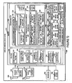
- FIG 56 is a drawing of an exemplary base station 5600, e.g., access node, implemented in accordance with the present invention and using methods of the present invention.
- Exemplary base station 5600 may be any of the base stations of the exemplary system of Figure 1 .
- Exemplary base station 5600 includes a receiver module 5602, a transmitter module 5604, a processor 5608, an I/O interface 5610, and a memory 5612, coupled together via a bus 5614 over which the various elements interchange data and information.
- the second decoder sub-module 5618 decodes information received in dedicated control channel segments corresponding to logical tones used in a split-tone DCCH mode of operation; the first and second decoder sub-modules (5616, 5618) implement different decoding methods.
- Memory 5612 includes routines 5620 and data/information 5622.
- the processor 5608 e.g. a CPU, executes the routines 5620 and uses the data/information 5622 in memory 5612 to control the operation of the base station 5600 and implement methods of the present invention.
- Routines 5620 include a communications routines 5624, and base station control routines 5626.
- the communications routines 5624 implement the various communications protocols used by the base station 5600.
- Base station control routines 5626 include a control channel resource allocation module 5628, a logical tone dedication module 5630, a wireless terminal dedicated control channel mode control module 5632, and a scheduler module 5634.
- the control channel resource allocation module 5628 allocates dedicated control channel resources including logical tones corresponding to dedicated control channel segments in an uplink.
- the control channel resource allocation module 5628 includes a full tone allocation sub-module 5636 and a split-tone allocation sub-module 5638.
- the full tone allocation sub-module 5636 allocates one of said logical tones corresponding to the dedicated control channel to a single wireless terminal.
- the split-tone allocation sub-module 5638 allocates different sets of dedicated control channel segments corresponding to one of the logical tones corresponding to the dedicated control channel to a plurality of wireless terminals to be used on a time shared basis with each of the plurality of wireless terminal being dedicated a different non-overlapping portion of time in which said logical tone is to be used on a time shared basis.
- base station 5600 for a given sector and uplink tone block uses a set of logical tones for the dedicated control channels, e.g., 31 logical tones, and at any given time the logical dedicated control channel tones are partitioned among full-tone mode logical tones and split-tone mode logical tones by logical tone dedication module 5630.
- Wireless terminal dedicated control channel mode control module 5632 generates control signals for indicating logical tone assignments and dedicated control channel mode assignments to wireless terminals.
- a wireless terminal is assigned an ON state identifier by the generated control signals, and the value of the ON identifier is associated with a particular logical dedicated control channel tone in the uplink channel structure.
- the assignments generated by module 5632 indicate that a wireless terminal corresponding to an assignment should operate in a full tone or split-tone mode with respect to an assigned logical tone.
- the split tone mode assignments further indicate which of a plurality of segments corresponding to an assigned logical dedicated control channel tone the wireless terminal corresponding to the assignment should use.
- Scheduler module 5634 schedules uplink and/or downlink traffic channel segments to wireless terminals, e.g., to wireless terminals which are using the base station 5600 as their point of network attachment, are in an On state and currently have an assigned dedicated control channel either in split-tone mode or full-tone mode.
- Data/information 5622 includes system data/information 5640, current DCCH logical tone implementation information 5642, received DCCH signal information 5644, DCCH control signal information 5646, and a plurality of sets of wireless terminal data/information 5648 (WT 1 data/information 5650,..., WT N data/information 5652).
- System data/information 5640 includes full tone mode DCCH information 5654, split-tone mode DCCH information 5656, downlink timing/frequency structure information 5658 and uplink timing/frequency structure information 5660.
- Full-tone mode DCCH information 5654 includes full-tone mode channel structure information 5662 and full tone mode segment coding information 5664.
- Split-tone mode DCCH information 5656 includes split-tone mode channel structure information 5666 and split-tone mode segment coding information 5668.
- Received DCCH information 5664 includes received DCCH reports associated with WT1, e.g., conveying uplink traffic channel requests, beacon ratio reports, power reports, self-noise reports, and/or signal two noise ratio reports.
- User data 5666 includes uplink and/or downlink traffic channel user data associated with WT1, e.g., voice data, audio data, image data, text data, file data, etc., corresponding to communications sessions and communicated via uplink and/or downlink traffic channel segments allocated to the WT1.
- FIG 57 is a drawing of an exemplary wireless terminal 5700, e.g., mobile node, implemented in accordance with the present invention and using methods of the present invention.
- Exemplary WT 5700 may be any of the wireless terminals of the exemplary system of Figure 1 .
- Exemplary wireless terminal 5700 includes a receiver module 5702, a transmitter module 5704, a processor 5706, user I/O devices 5708, and a memory 5710 coupled together via a bus 5712 over which the wireless terminal interchanges data and information.
- the receiver module 5702 e.g., an OFDM receiver, is coupled to a receive antenna 5703 via which the wireless terminal 5700 receives downlink signals from base stations.
- Downlink signals received by the wireless terminal 5700 include beacon signals, pilot signals, registration response signals, power control signals, timing control signals, assignments ofwireless terminal identifiers, e.g., an On state identifier corresponding to a DCCH channel logical tone, other DCCH assignment information, e.g., used to identify a set of DCCH channel segments in a uplink repetitive structure, assignments of uplink traffic channel segments and/or assignment of downlink traffic channel segments.
- Receiver module 5702 includes a decoder 5714 via which the wireless terminal 5700 decodes received signals which had been encoded prior to transmission by the base station.
- the transmitter module 5704 e.g., an OFDM transmitter, is coupled to a transmit antenna 5705 via which the wireless terminal 5700 transmits uplink signals to base stations.
- Uplink signals transmitted by the wireless terminal 5700 include: access signals, handoff signals, power control signals, timing control signals, DCCH channel segment signals, and uplink traffic channel segment signals.
- DCCH channel segment signals include initial DCCH report set signals and scheduled DCCH report set signals.
- the same antenna is used for transmitter and receiver.
- Transmitter module 5704 includes an encoder 5716 via which the wireless terminal 5700 encodes at least some uplink signals prior to transmission.
- Routines 5718 include a communications routine 5722 and wireless terminal control routines 5724.
- the communications routine 5722 implements the various communications protocols used by the wireless terminal 5700.
- the wireless terminal control routines 5724 control operation of the wireless terminal 5700 including controlling operation of the receiver module 5702, transmitter module 5704 and user I/O devices 5708.
- Wireless terminal control routines 5724 include a report transmission control module 5726, an initial report generation module 5728, a scheduled report generation module 5730, and a timing control module 5732.
- the report transmission control module 5726 includes a handoff detection module 5734.
- the initial report generation module 5728 includes a report size set determination sub-module 5736.
- Report transmission control module controls the wireless terminal 5700 to transmit an initial information report set following the transition by said wireless terminal from a first mode of operation to a second mode of operation and to transmit scheduled reports according to an uplink reporting schedule following transmission of said initial report set.
- the first mode of operation is one of a sleep state and a hold state and the second mode of operation is an ON state, e.g., an On state in which the wireless terminal is permitted to transmit user data.
- the wireless terminal in the second mode, e.g., ON state, the wireless terminal has a dedicated uplink reporting channel for reporting information including requests for uplink traffic channel resources which can be used to transmit user data.
- the wireless terminal in the first mode, e.g., sleep state or Hold state, the wireless terminal does not have a dedicated uplink reporting channel for reporting information including requests for uplink traffic channel resources which can be used to transmit user data.
- the handoff detection module 5734 detects a handoff from a first access node attachment point to a second access node attachment point and controls the wireless terminal to generate an initial information report set following certain types of identified handoffs, the generated initial information report set to be transmitted to the second access node attachment point.
- the certain types of identified handoffs include, in some embodiments, handoffs in which the wireless terminal transitions though an access state of operation with respect to the second access node attachment point before going to an On state with respect to the second access node.
- the first and access node attachment points may correspond to different access nodes located in different cells which are not timing synchronized with respect to one another and the wireless terminal needs to go through the access state to achieve timing synchronization with respect to the second access node.
- the handoff detection module 5734 controls the wireless terminal to forgo the generation and transmission of an initial information report following a handoff from a first access node attachment point to a second access node attachment point, under certain other types of handoffs, and to proceed directly into transmitting scheduled report information sets.
- the first and second access node attachment points may be timing synchronized and correspond to the same access node, e.g., different adjacent sectors and/or tone blocks
- the certain other type of handoff is, e.g., a handoff which involves a transition from an ON state with respect to the first attachment point to an On state with respect to the second attachment point without having to transition through an access state.
- Report set size determination sub-module 5736 determines an initial report set size as a function of the point in time with respect to the uplink transmission schedule at which said initial report is to be transmitted.
- an initial report information set size is, in some embodiments, one of a plurality of set sizes, e.g., corresponding to one, two, three, four or five DCCH segments, depending upon where in the uplink timing structure the initial report transmission is to be started, e.g., the point within a superslot.
- the types of reports included in the initial report set is a function of where in the uplink timing structure the initial report transmission is to be started, e.g., depending upon the superslot location within a beaconslot.
- Data/information 5720 includes user/device/session/resource information 5738, system data/information 5740, base station identification information 5742, terminal identification information 5744, timing control information 5746, current state of operation information 5748, DCCH channel information 5750, initial report time information 5752, determined initial report size information 5754, initial report control information 5756, generated initial report information set 5758, generated scheduled information report information sets 5760, handoff information 5762, uplink traffic request information 5764, and user data 5766.
- the initial report control information includes size information 5768 and time information 5770.
- User/device/session/resource information 5738 includes information user identification information, e.g., user log-in IDs, passwords and user priority information, device information, e.g., device identification information and device characteristic parameters, session information, e.g., information pertaining to peers, e.g., other WTs in communications sessions with WT 5700, communications session information such as session keys, addressing and/or routing information, and resource information, e.g., uplink and/or downlink air link segments and/or identifiers allocated to the WT 5700.
- user identification information e.g., user log-in IDs, passwords and user priority information
- device information e.g., device identification information and device characteristic parameters
- session information e.g., information pertaining to peers, e.g., other WTs in communications sessions with WT 5700
- communications session information such as session keys, addressing and/or routing information
- resource information e.g., uplink and/or downlink air link segments and
- Downlink timing/frequency structure information 5776 includes downlink logical tone structure identifying various channels and segments, e.g., assignment, beacon, pilot, downlink traffic channel, etc., in a repetitive downlink structure and identifying timing, e.g., OFDM symbol time duration, indexing, groupings of OFDM symbol times, e.g., into slots, superslots, beaconslots, ultraslots, etc.
- Information 5776 also includes base station identification information, e.g., cell, sector, and carrier/tone block identification information.
- Information 5776 also incudes downlink tone hopping information used to map logical tones to physical tones.
- Uplink timing/frequency structure information 5778 includes uplink logical tone structure identifying various channels and segments, e.g., access, assignment, power control channels, timing control channels, dedicated control channel (DCCH), uplink traffic channel, etc., in a repetitive uplink structure and identifying timing, e.g., OFDM symbol time duration, indexing, groupings of OFDM symbol times, e.g., into halfslots, slots, superslots, beaconslots, ultraslots, etc., as well as information correlating the downlink to uplink timing BS1, e.g., a timing offset between the uplink and downlink repetitive timing structures at the base station.
- Information 5778 also includes uplink tone hopping information used to map logical tones to physical tones.
- Recurring uplink reporting structure information 5780 includes DCCH reports' format information 5782, and DCCH report sets information 5784.
- DCCH report sets information 5784 includes sets information 5786 and time information 5788.
- the recurring uplink reporting structure information 5780 includes, in some embodiments, information identifying a recurring pattern of a fixed number of indexed DCCH segments, e.g., 40 indexed DCCH segments.
- Each of the indexed DCCH segments includes one of more types of DCCH reports, e.g., uplink traffic channel request reports, interference reports such as beacon ratio reports, different SNR reports, etc.
- Initial DCCH report information 5790 includes format information 5792 and report set information 5794.
- the format information 5792 includes information indicating the format of initial reports sets to be transmitted.
- the formats of the initial reports, groupings, and/or number of initial reports to be transmitted in an initial report set depend on the time at which the initial report set is to be transmitted, e.g., with respect to a recurring uplink timing structure.
- Report set information 5794 includes information identifying various initial reports sets, e.g., number of reports, types of reports, and ordered grouping of reports, e.g., associated with DCCH segments to be communicated in the initial report.
- Timing control information 5746 includes received downlink signals from the base station used by the timing control module 5732 for correlating the uplink reporting structure, at least some of the received downlink timing control signals being used for closed loop timing control. Timing control information 5746 also includes information identifying the current timing with respect to repetitive uplink and downlink timing structures, e.g., an OFDM symbol transmission time period with respect to the structures.
- Current state of operation information 5748 includes information identifying the wireless terminal's current state of operation, e.g., sleep, hold, ON. Current state of operation information 5748 also includes information identifying when a WT is in a full-tone DCCH mode of operation or in a split-tone mode of DCCH operation, in an access process, or in the process of a handoff.
- Generated initial report information set 5758 is an initial report set generated by wireless terminal initial report generation module 5728 using the data/information 5720 including initial DCCH report structure information 5790, initial report control information 5756, and information to be included in the reports of the initial report such as, e.g., uplink traffic channel request information 5764, SNR information, and measured interference information.
- Generated scheduled report information sets 5760 includes generated scheduled information report sets, e.g., each set corresponding to a scheduled DCCH segment to be used by the wireless terminal.
- FIG 58 is a drawing of an exemplary base station 5800, e.g., access node, implemented in accordance with the present invention and using methods of the present invention.
- Exemplary base station 5800 may be any of the base stations of the exemplary system of Figure 1 .
- Exemplary base station 5800 includes a receiver module 5802, a transmitter module 5804, a processor 5806, an I/O interface 5808, and a memory 5810 coupled together via a bus 5812 over which the various elements interchange data and information.
- Receiver module 5802 receives uplink signals from a plurality of wireless terminals via receive antenna 5803.
- the uplink signals include dedicated control channel report information sets from wireless terminals, access signals, requests for mode changes, and uplink traffic channel segment signals.
- Receiver module 5802 includes a decoder module 5814 for decoding uplink signals which were encoded prior to transmission by the wireless terminals.
- I/O interface 5808 provides an interface for coupling the base station 5800 to other network nodes, e.g., other base stations, AAA server nodes, home agent nodes, routers, etc., and/or the Internet. I/O interface 5808 allows a wireless terminal using base station 5800 as its point of network attachment to communicate with peer nodes, e.g., other wireless terminals, in different cells, via a backhaul communication network.
- network nodes e.g., other base stations, AAA server nodes, home agent nodes, routers, etc.
- I/O interface 5808 allows a wireless terminal using base station 5800 as its point of network attachment to communicate with peer nodes, e.g., other wireless terminals, in different cells, via a backhaul communication network.
- Memory 5810 includes routines 5820 and data/information 5822.
- the professor 5806 e.g. a CPU, executes the routines 5820 and uses the data/information 5822 in memory 5810 to control the operation of the base station 5800 and implement methods of the present invention.
- Routines 5820 include a communications routines 5824'and base station control routines 5826.
- the communications routines 5824 implement the various communications protocols used by the base station 5800.
- Base station control routines 5826 include a scheduler module 5828, a report set interpretation module 5830, an access module 5832, a handoff module 5834, and a registered wireless terminal state transition module 5836.
- Scheduler module 5828 schedules uplink and/or downlink traffic channel segments to wireless terminals, e.g., to wireless terminals which are using the base station 5800 as their point of network attachment, are in an On state and currently have an assigned dedicated control channel either in split-tone mode or full-tone mode.
- Report set interpretation module 5830 e.g., a DCCH report set interpretation module, includes an initial report set interpretation sub-module 5838 and a recurring reporting structure report set interpretation sub-module 5840. Report set interpretation module 5830 interprets each received DCCH report set in accordance with the initial DCCH report information 5850 or the recurring uplink reporting structure information 5848. Report set interpretation module 5830 is responsive to transitions by wireless terminals to the ON state.
- Report set interpretation module 5830 interprets as an initial information report set, a DCCH report information set received from a wireless terminal immediately after one of: a migration of the wireless terminal to an On state from a hold state with respect to the current connection, a migration of the wireless terminal to an On state from an access state with respect to the current connection, and a migration of the wireless terminal to an On state from an On state which existed with respect to another connection prior to a handoff to the base station.
- Report set interpretation module 5830 includes an initial report set interpretation sub-module 5838 and a recurring reporting structure report set interpretation sub-module 5840.
- Initial report set interpretation sub-module 5838 processes received information report sets, e.g., corresponding to a received DCCH segment, which have been determined to be an initial DCCH report set, using data/information 5822 including initial DCCH report information 5850, to obtain interpreted initial report set information.
- Recurring reporting structure report set interpretation sub-module 5840 processes received information report sets, e.g., corresponding to a received DCCH segment, which have been determined to be a recurring reporting structure DCCH report set, using data/information 5822 including recurring uplink reporting structure information 5848, to obtain interpreted recurring structure report set information.
- Access module 5832 controls operations relating to wireless terminal access operations. For example, a wireless terminal transitions through the access mode to an On state achieving uplink timing synchronization with a base station attachment point and-receiving a WT On state identifier associated with a logical DCCH channel tone in the uplink timing and frequency structure to be used to communicate uplink DCCH segment signals. Following this transition to the On state, the initial report set interpretation sub-module 5838 is activated to process DCCH segments for the remainder of a superslot, e.g., one, two, three, four, or five DCCH segments, then operation is transferred to the recurring reporting structure report set interpretation sub-module 5840 to process subsequent DCCH segments from the wireless terminal.
- the number of DCCH segments and/or the format used for those segments processed by module 5838 before transferring control to module 5840 is a function of the time at which the access occurs with respect to the recurring uplink DCCH reporting structure.
- Handoff module 5834 controls operations pertaining to handoffs a wireless terminal from one attachment point to another attachment point. For example, a wireless terminal in an ON state of operation with a first base station attachment point may perform a handoff operation to base station 5800 to transition into an ON state with respect to a second base station attachment point, the second base station attachment point being a base station 5800 attachment point, and the handoff module 5834 activates the initial report set interpretation sub-module 5838.
- Registered wireless terminal state transition module 5836 performs operations related to mode changes of wireless terminals which have registered with the base station. For example, a registered wireless terminal currently in a Hold state of operation in which the wireless terminal is precluded from transmitting uplink user data may transition to an On state of operation in which the WT is assigned an ON state identifier associated with a DCCH logical channel tone and in which the wireless terminal can receive uplink traffic channel segments which are to be used to communicate uplink user data. Registered WT state transition module 5836 activates initial report set interpretation sub-module 5838 in response to the mode transition from Hold to ON of the wireless terminal.
- Base station 5800 manages a plurality of ON state wireless terminals. For a set of received DCCH segments, communicated from different wireless terminals, corresponding to the same time interval, the base station, at some times, processes some of the segments using the initial report set interpretation sub-module 5838 and some of the reports using the recurring reporting structure set interpretation sub-module 5840.
- Data/information 5822 includes system data/information 5842, access signal information 5860, handoff signal information 5862, mode transition signaling information 5864, time information 5866, current DCCH logical tone implementation information 5868, received DCCH segments information 5870, base station identification information 5859, and WT data/information 5872.
- System data/information 5842 includes downlink timing/frequency structure information 5844, uplink timing/frequency structure information 5846, recurring uplink reporting structure information 5848, and initial DCCH report information 5850.
- Recurring uplink reporting structure information 5848 includes DCCH reports' format information 5852 and DCCH report sets information 5854.
- DCCH report sets information 5854 includes sets information 5856 and time information 5858.
- Initial DCCH report information 5850 includes format information 5851 and report set information 5853.
- Downlink timing/frequency structure information 5844 includes downlink logical tone structure identifying various channels and segments, e.g., assignment, beacon, pilot, downlink traffic channel, etc., in a repetitive downlink structure and identifying timing, e.g., OFDM symbol time duration, indexing, groupings of OFDM symbol times, e.g., into slots, superslots, beaconslots, ultraslots, etc.
- Information 5844 also includes base station identification information, e.g., cell, sector, and carrier/tone block identification information.
- Information 5844 also includes downlink tone hopping information used to map logical tones to physical tones.
- Uplink timing/frequency structure information 5846 includes uplink logical tone structure identifying various channels and segments, e.g., access, assignment, power control channels, power control channels, dedicated control channel (DCCH), uplink traffic channel, etc., in a repetitive uplink structure and identifying timing, e.g., OFDM symbol time duration, indexing, groupings of OFDM symbol times, e.g., into halfslots, slots, superslots, beaconslots, ultraslots, etc., as well as information correlating the downlink to uplink timing, e.g., a timing offset between the uplink and downlink repetitive timing structures at the base station.
- Information 5846 also includes uplink tone hopping information used to map logical tones to physical tones.
- Recurring uplink reporting structure information 5848 includes DCCH reports' format information 5852, and DCCH report sets information 5854.
- DCCH report sets information 5854 includes sets information 5856 and time information 5858.
- the recurring uplink reporting structure information 5848 includes, in some embodiments, information identifying a recurring pattern of a fixed number of indexed DCCH segments, e.g., 40 indexed DCCH segments.
- Each of the indexed DCCH segments includes one of more types of DCCH reports, e.g., uplink traffic channel request reports, interference reports such as beacon ratio reports, different SNR reports, etc.
- DCCH reports' format information 5852 e.g., for each type of report associating a fixed number of information bits with different potential bit patterns and interpretations of information conveyed by the corresponding bit pattern.
- DCCH report sets information 5854 identifies different grouping of reports associated with different indexed segments in the recurring DCCH reporting structure.
- Sets information 5856 identifies for each indexed DCCH segment identified by a corresponding time information entry 5858 a set of reports communicated in the segment and the order of those reports in the segment.
- Initial DCCH report information 5850 includes format information 5851 and report set information 5853.
- the format information 5851 includes information indicating the format of initial reports sets to be transmitted. In some embodiments, the formats of the initial reports, groupings, and/or number of initial reports to be transmitted in an initial report set depend on the time at which the initial report set is to be transmitted, e.g., with respect to a recurring uplink timing structure.
- Report set information 5853 includes information identifying various initial reports sets, e.g., number of reports, types of reports, and ordered grouping of reports, e.g., associated with DCCH segments to be communicated in the initial report set.
- Base station identification information 5859 includes information identifying the base station attachment point being used by the wireless terminal.
- Base station identification information 5859 includes physical attachment point identifiers, e.g., cell, sector and carrier/tone block identifiers associated with the base station attachment point. In some embodiments, at least some of the base station identifier information is communicated via beacon signals.
- Base station identification information also includes base station address information.
- Access signal information 5860 includes access request signals received from wireless terminals, access response signals sent to wireless terminal, timing signals related to the access, and base station internal signaling to activate the initial report interpretation sub-module 5838 in response to.a transition from the access state to the On state for a wireless terminal.
- Handoff signal information 5862 includes information pertaining to handoff operations including handoff signaling received from other base stations and base station internal signaling to activate the initial report interpretation sub-module 5838 in response to a transition from a WT ON state of another connection to a WT On state with respect to a base station 5800 attachment point connection.
- Mode transitioning signaling information 5864 includes signals between a currently registered wireless terminal and base station 5800 regarding state changes, e.g., a change from hold state to On state, and base station internal signaling to activate the initial report set interpretation sub-module 5838 in response to state transitions, e.g., Hold to On.
- Registered WT state transition module 5836 also deactivates recurring reporting structure report set interpretation sub-module 5840 with respect to a wireless terminal in response to some state changes, e.g., a wireless terminal transition from ON state to one of Hold state, sleep state, or Off state.
- Time information 5866 includes current time information, e.g., an indexed OFDM symbol time period within a recurring uplink timing structure being used by the base station.
- Current DCCH logical tone implementation information 5868 includes information identifying which of the base stations logical DCCH tones are currently in a full-tone DCCH mode and which are in a split-tone DCCH mode.
- Received DCCH segments information 5860 includes information from received DCCH segments corresponding to a plurality of WT users currently assigned logical DCCH tones.
- step 5910 the wireless terminal proceeds to step 5912 if the wireless terminal has determined that it in full-tone DCCH mode, while operation proceeds to step 5914 if the wireless terminal has determined that it in split-tone DCCH mode.
- the wireless terminal identifies DCCH communication segments allocated to the wireless terminal using time information 5906 and the identified logical DCCH tone. For example, in an exemplary embodiment, for each beacon slot, the wireless terminal identifies a set of 40 indexed DCCH segments corresponding to assigned logical DCCH tone. Operation proceeds from step 5912 to step 5916, for each identified communications segment. In step 5916, the wireless terminal using time information 5906, the indexed value of the DCCH segment within the recurring structure, and stored information associating sets of report types with each indexed segment, identifies a set of report types to be communicated in the DCCH communications segment. Operation proceeds from step 5916 via connecting node A 5920 to step 5924.
- step 5924 the wireless terminal checks as to whether any of report types identified in step 5916 include a flexible report. If any of the identified report types indicate a flexible report, then operation proceeds from step 5924 to step 5928; otherwise operation proceeds from step 5924 to step 5926.
- step 5926 the wireless terminal, for each fixed type information report of the segment, maps the information to be conveyed to a fixed number of information bits corresponding to the report size, said fixed type of information reports being dictated by a reporting schedule. Operation proceeds from step 5926 to step 5942.
- Step 5928 the wireless terminal selects which type of report from among a plurality of fixed type information report types to include as a flexible report body
- Step 5928 includes sub-step 5930.
- the wireless terminal performs the selection as a function of a report prioritization operation.
- Sub-step 5930 includes sub-step 5932 and 5934.
- the wireless terminal considers the amount of uplink data queued for communication to the access node, e.g., the backlog in a plurality of request queues, and at least one signal interference measurement, e.g., a beacon ratio report.
- a DCCH segment including a flexible report when in the full-tone mode utilizes the full number of information bits communicated by the segment for itself, e.g., the segment conveys 6 information bits, 2 bits are used for identifying the type of report and 4 bits used for conveying the body of the report.
- step 5940 is not performed.
- the total number of bits conveyed by a DCCH segment in the full-tone DCCH mode is greater than the number of bits represented by the flexible report and step 5940 is included to utilize the remaining information bits of the segment.
- the segment conveys a total of 7 information bits 6 of which are utilized by the flexible report and 1 is used for a fixed one information bit uplink traffic request report.
- step 5942 the wireless terminal performs coding and modulation operations to generate a set of modulation symbols to represent the one or more reports to be communicated in the DCCH segment. Operation proceeds from step 5942 to step 5944.
- step 5944 the wireless terminal, for each modulation symbol of the set of generated modulation symbols determines, using time information 5906 and tone hopping information, the physical tone to be used to convey the modulation symbol.
- each DCCH segment corresponds to 21 OFDM tone-symbols each tone symbol being used to convey one QPSK modulation symbol, each of the 21 OFDM tone-symbols corresponding to the same logical DCCH tone; however due to uplink tone hopping, 7 OFDM tone symbols in a first set of seven successive OFDM symbol time periods corresponding to a first physical tone, a second set of seven OFDM tone-symbols in a second set of seven successive OFDM symbol time periods corresponding to a second physical tone, and a third set of seven successive OFDM symbol time periods corresponding to a third physical tone, the first second and third physical tones being different. Operation proceeds from step 5944 to step 5946. In step 5946, the wireless terminal transmits each modulation symbol of the DCCH segment using the determined corresponding physical tone.
- the wireless terminal identifies DCCH communication segments allocated to the wireless terminal using time information 5906, the identified logical DCCH tone, and the information identifying the one among the plurality of sets of DCCH segments. For example, in an exemplary embodiment, for each beacon slot, the wireless terminal identifies a set of 13 indexed DCCH segments corresponding to assigned logical DCCH tone. Operation proceeds from step 5914 to step 5918, for each identified DCCH communications segment. In step 5918, the wireless terminal using time information 5906, the indexed value of the DCCH segment within the recurring structure, and stored information associating sets of report types with each indexed segment, identifies a set of report types to be communicated in the DCCH communications segment. Operation proceeds form step 5916 via connecting node B 5922 to step 5948.
- step 5948 the wireless terminal checks as to whether any of report types identified in step 5918 include a flexible report. If any of the identified report types indicate a flexible report, then operation proceeds from step 5948 to step 5952; otherwise operation proceeds from step 5948 to step 5950.
- step 5952 the wireless terminal selects which type of report from among a plurality of fixed type information report types to include as a flexible report body.
- Step 5952 includes sub-step 5954.
- the wireless terminal performs the selection as a function of a report prioritization operation.
- Sub-step 5954 includes sub-step 5956 and 5958.
- the wireless terminal considers the amount of uplink data queued for communication to the access node, e.g., the backlog in a plurality of request queues, and at least one signal interference measurement, e.g., a beacon ratio report.
- the wireless terminal determines an amount of change in information previously reported in at least one report, e.g., a measured change in a downlink saturation level of self-noise SNR report. Operation proceeds from step 5952 to step 5960.
- a DCCH segment including a flexible report when in the split-tone mode utilizes the full number of information bits communicated by the segment for itself, and in such an embodiment, step 5964 is not performed.
- the total number of bits conveyed by a DCCH- segment in the split-tone DCCH mode is greater than the number of bits represented by the flexible report and step 5940 is included to utilize the remaining information bits of the segments.
- the segment conveys a total of 8 information bits 6 of which are utilized by the flexible report and 1 information bit is used for a fixed one information bit uplink traffic request report, and 1 information bit is used for another predetermined report type.
- the size of the body of the flexible report varies corresponding to different selections of the type of report to be conveyed by the flexible report, e.g., a 4 bit uplink traffic channel request or a five bit uplink transmission power backoff report, and the remainder of the available bits in the segment can be allocated to predetermined fixed report types, e.g., 1 or 2 bits.
- step 5966 the wireless terminal performs coding and modulation operations to generate a set of modulation symbols to represent the one or more reports to be communicated in the DCCH segment. Operation proceeds from step 5966 to step 5968.
- step 5968 the wireless terminal, for each modulation symbol of the set of generated modulation symbols determines, using time information 5906 and tone hopping information, the physical tone to be used to convey the modulation symbol.
- each DCCH segment corresponds to 21 OFDM tone-symbols each tone symbol being used to convey one QPSK modulation symbol, each of the 21 OFDM tone-symbols corresponding to the same logical DCCH tone; however due to uplink tone hopping, 7 OFDM tone symbols in a first set of seven successive OFDM symbol time periods corresponding to a first physical tone, a second set of seven OFDM tone-symbols in a second set of seven successive OFDM symbol time periods corresponding to a second physical tone, and a third set of seven successive OFDM symbol time periods corresponding to a third physical tone, the first second and third physical tones being determined in accordance with tone hopping information and may be different. Operation proceeds from step 5968 to step 5970. In step 5970, the wireless terminal transmits each modulation symbol of the DCCH segment using the determined corresponding physical tone.
- Figure 60 is a flowchart 6000 of an exemplary method of operating a wireless terminal to provide transmission power information to a base station in accordance with the present invention. Operation starts in step 6002.
- the wireless terminal may have been previously powered on, established a connection with a base station, have transitioned in the ON state of operation, and been assigned dedicated control channel segments to use in either a full-tone or split tone mode of DCCH operation.
- the wireless terminal In step 6004, the wireless terminal generates a power report indicating a ratio of a maximum transmit power of the wireless terminal to the transmit power of a reference signal having a power level known to the wireless terminal at a point in time corresponding to the power report.
- the power report is a backoff report, e.g., a wireless terminal transmission power backoff report, indicating a dB value.
- the maximum transmission power value depends on a power output capability of the wireless terminal.
- the maximum transmission power is specified by a government regulation limiting the maximum output power level of the wireless terminal.
- the reference signal is controlled by the wireless terminal based upon at least one closed loop power level control signal received from a base station.
- the reference signal is a control information signal transmitted over a dedicated control channel to the base station.
- the reference signal in some embodiments, is measured for received power level by the base station to which it is transmitted.
- the dedicated control channel is a single tone control channel which corresponds to a single logical tone dedicated to the wireless terminal for use in transmitting control information.
- the power report is a power report corresponding to a single instant in time.
- the known reference signal is a signal transmitted on the same channel as the power report, e.g., the same DCCH channel.
- Step 6004 includes sub-step 6006, sub-step 6008, sub-step 6010, and sub-step 6012.
- the wireless terminal In sub-step 6010, the wireless terminal generates a power report in accordance with a first format, e.g., a 5 information bit power report. For example the result of sub-step 6006 is compared to a plurality of different levels, each level corresponding to a different 5 bit pattern, the level closes to the result of sub-step 6006 is selected for the report, and the bit pattern corresponding to that level is used for the report. In one exemplary embodiment, the levels range from 6.5dBs to 40dBs. (See Figure 26 .) In sub-step 6012 the wireless terminal generates a power report in accordance with a second format, e.g., a 4 information bit power report.
- a second format e.g., a 4 information bit power report.
- the result of sub-step 6006 is compared to a plurality of different levels, each level corresponding to a different 4 bit pattern, the level closet to the result of sub-step 6006 is selected for the report, and the bit pattern corresponding to that level is used for the report.
- the levels range from 6dBs to 36dBs. (See Figure 35 .) Operation proceeds from step 6004 to step 6014.
- the wireless terminal combines the generated power report with additional information bit(s), e.g., 1 additional information bit, and jointly codes the set of combined information bits, e.g., set of 6 information bits, to generate a set of modulation symbols for a DCCH segment, e.g., a set of 21 modulation symbols.
- additional information bit is, in some embodiments, a single information bit uplink traffic channel resource request report.
- the wireless terminal combines the generated power report with additional information bit(s), e.g., 4 additional information bits, and jointly codes the set of combined information bits, e.g., set of 8 information bits, to generate a set of modulation symbols for a DCCH segment, e.g., a set of 21 modulation symbols.
- additional information bit(s) e.g., 4 additional information bits
- the set of 4 additional information bit is, in some embodiments, a 4 information bit uplink traffic channel resource request report. Operation proceeds from sub-step 6018 or sub-step 6020 to sub-step 6022.
- sub-step 6022 the wireless terminal determines the single OFDM tone used during each of a plurality of consecutive OFDM symbol transmission time periods for the DCCH segment.
- Sub-step 6022 includes sub-step 6024 and sub-step 6026.
- sub-step 6024 the wireless terminal determines the logical DCCH channel tone assigned to the wireless terminal, and in sub-step 6026, the wireless terminal determines a physical tone to which the logical DCCH channel tone corresponds at different points in time based on tone hopping information.
- the WT reports the number of MAC frames in the 4 request groups that the WT may intend to transmit. In the ARQ protocol, those MAC frames are marked as "new" or "to be retransmitted".
- the WT reports the information about N[0:3] to the base station sector (BSS) so that the BSS can utilize the information in an uplink (UL) scheduling algorithm to determine the assignment of uplink traffic channel (UL.TCH) segments.
- BSS base station sector
- UL uplink
- the WT uses an ULRQST1 to report N[0]+N[1] according to Table 6100 of Figure 61 .
- the WT uses only one request dictionary.
- the WT uses the default request dictionary.
- the WT and the BSS uses an upper layer configuration protocol.
- the WT migrates from the ON state to the HOLD state, the WT keeps the last request dictionary used in the ON state so that when the WT migrates from the HOLD state to the ON state later, the WT continues to use the same request dictionary until the request dictionary is explicitly changed.
- the WT leaves the ACTIVE state, then the memory of the last request dictionary used is cleared.
- the base station sector broadcasts the value of ulTCHrateFlashAssignmentOffset in a downlink broadcast channel.
- the WT uses ulTCHrateFlashAssignmentOffset equal to OdB until the WT receives the value from the broadcast channel.
- the WT uses an ULRQST3 or ULRQST4 to report the actual N[0:3] of the MAC frame queues according to a request dictionary.
- a request dictionary is identified by a request dictionary (RD) reference number.
- any ULRQST4 or ULRQST3 report may not completely include the actual N[0:3].
- a report is in effect a quantized version of the actual N[0:3].
- a general guideline is that the WT should send a report to minimize the discrepancy between the reported and the actual MAC frames queues first for request groups 0 and 1, and then for request group 2, and finally for request group 3.
- the WT has the flexibility of determining a report to benefit the WT the most. For example, when the WT is using the request dictionary 2, the WT may use an ULRQST4 to report N[1]+N[3] and use an ULRQST3 to report N[2].
- Table 6300 of Figure 63 and Table 6400 of Figure 64 define an exemplary request dictionary with the RD reference number equal to 0.
- d 123 ceil(((N[1]+N[2]+N[3]-N 123.min )/(y*g)), whereN 123 , min and g are variables determined by the most recent ULRQST4 report as per Table 6300.
- Table 6500 of Figure 65 and Table 6600 of Figure 66 define an exemplary request dictionary with the RD reference number equal to 1.
- Table 6900 of Figure 69 and Table 7000 of Figure 70 define an exemplary request dictionary with the RD reference number equal to 3.
- FIG 71 is a drawing of an exemplary wireless terminal 7100, e.g., mobile node, implemented in accordance with the present invention and using methods of the present invention.
- Exemplary WT 7100 may be any of the wireless terminals of the exemplary system of Figure 1 .
- Exemplary WT 7100 may be any of the WTs (136, 138, 144, 146, 152, 154, 168, 170, 172, 174, 176, 178) of exemplary system 100 of Figure 1 .
- Exemplary wireless terminal 7100 includes a receiver module 7102, a transmitter module 7104, a processor 7106, user I/O devices 7108, and a memory 7110 coupled together via a bus 7112 via which the various elements may interchange data and information.
- Memory 7110 includes routines 7118 and data/information 7120.
- the processor 7106 e.g., a CPU, executes the routines 7118 and uses the data/information 7120 in memory 7110 to control the operation of the wireless terminal 7100 and implement methods of the present invention.
- Receiver module 7102 e.g., an OFDM receiver
- Receiver module 7102 is coupled to receive antenna 7103 via which the wireless terminal 7100 receives downlink signals from base stations.
- Receiver module 7102 includes a decoder 7114 which decodes at least some of the received downlink signals.
- Transmitter module 7104 e.g., an OFDM transmitter, is coupled to a transmit antenna 7105 via which the wireless terminal 7100 transmits uplink signals to base stations.
- Transmitter module 7104 is used for transmitting a plurality of different types of fixed reports using uplink dedicated control channel segments dedicated to the wireless terminal.
- Transmitter module 7104 is also used for transmitting flexible reports using uplink dedicated control channel segments dedicated to the wireless terminal, the uplink DCCH segments which include a flexible report being the same size as at least some of the uplink DCCH segments which include fixed type reports and do not include a flexible report.
- Transmitter module 7104 includes an encoder 7116 which is used to encode at least some of the uplink signals prior to transmission.
- each individual dedicated control channel uplink segment is encoded independently of other dedicated control channel uplink segments.
- the same antenna is used for both the transmitter and receiver.
- User I/O devices 7108 e.g., microphone, keyboard, keypad, switches, camera, speaker, display, etc., are used to input/output user data, control applications, and control the operation of the wireless terminal, e.g., allowing a user of WT 7100 to initiate a communications session.
- Routines 7118 includes a communications routine 7122 and wireless terminal control routines 7124.
- Communications routine 7122 performs various communications protocols used by wireless terminal 7100.
- Wireless terminal control routines 7124 include a fixed type report control module 7126, a flexible type report control module 7128, an uplink tone hopping module 7130, an identifier module 7132, and a coding module 7134.
- Fixed type report control module 7126 controls the transmission of a plurality of different types of fixed type information reports according to a reporting schedule, said fixed type information reports being of a type dictated by the reporting schedule.
- Flexible type report control module 7128 controls transmission of flexible reports at predetermined locations in the reporting schedule, said flexible type reports being of report types selected by the flexible report control module from a plurality of reports which can be reported using a flexible report.
- Flexible report control module 7128 includes a report prioritization module 7136.
- the report prioritization module 7136 takes into consideration the amount of uplink data queued for communication to the base station and a least one signal interference measurement, when determining which one of a plurality of alternative reports should be communicated in a flexible report.
- Report prioritization module 7138 also includes a change determination module 7138, which determines an amount of change in information previously reported in at least one report.
- Uplink tone hopping module 7130 determines, based on stored tone hopping information, for transmission purposes, the physical tone corresponding to the logical assigned DCCH channel tone at different points in time corresponding to the transmission of dedicated segments. For example, in one exemplary embodiments, a DCCH segment corresponds to three dwells, each dwell using the same physical tone for seven successive OFDM symbol transmission time intervals; however, the physical tone associated with the different dwells is determined by tone hopping information and may be different.
- Identifier module 7132 generates flexible type report identifiers to be communicated with flexible reports, the report type identifiers communicated with an individual flexible report indicating the type of flexible report being communicated. In various embodiments, the identifier module 7132 generates a report which indicates the type of flexible report which corresponds to the report type identifier. In this exemplary embodiment, an individual flexible type report is communicated in the same DCCH segment with the corresponding report type identifier. In this exemplary embodiment, identifier module 7132 is not used for fixed type reports as there is a predetermined understanding between the base station and wireless terminal as to the type of fixed report being communicated based on position of the fixed report within the recurring reporting structure.
- Coding module 7134 codes an individual flexible report identifier and a corresponding flexible report together in a single coding unit corresponding to the DCCH communications segment in which they are transmitted. In some embodiments, coding module 7134 operates in conjunction with encoder 7116.
- Data/information 7120 includes user/device/session/resource information 7140, system data/information 7142, generated fixed type report 1 7144, ..., generated fixed type report n 7146, selected type of flexible report 7148, generated flexible report 7150, flexible report type identifier 7152, coded DCCH segment information 7154, DCCH channel information 7156 including assigned logical tone information 7158, base station identification information 7160, terminal identification information 7162, timing information 7164, amount of uplink data queued 7166, signal interference information 7168, and report change information 7170.
- Assigned logical tone information 7158 identifies a base station assigned single logical uplink dedicated control channel tone to be used by the WT 7100 for communicating uplink DCCH segment signals conveying fixed and flexible reports.
- the single assigned logical DCCH tone is associated with a base station assigned ON state identifier.
- User/device/session/resource information 7140 includes information pertaining to communications sessions, e.g., peer node information, addressing information, routing information, state information, and resource information identifying uplink and downlink air link resources, e.g., segments, allocated to WT 7100.
- Generated fixed type of report 1 7144 is a fixed type.report corresponding to one of the plurality of fixed types of reports supported by WT 7100 and has been generated using fixed type report information 7188.
- Generated fixed type of report n 7146 is a fixed type report corresponding to one of the plurality of fixed types of reports supported by WT 7100 and has been generated using fixed type report information 7188.
- Selected type of flexible report 7148 is information identifying the wireless terminal's selection for the type of report to be communicated in the flexible report, e.g., a pattern of two bits identifying one of four patterns corresponding to a TYPE 2 report of Figure 31 .
- Generated flexible report 7150 is a flexible type report corresponding to one of the plurality of types of reports which may be selected by WT 7100 to be communicated in a flexible report and has been generated using flexible type report information 7190, e.g., a pattern of four bits corresponding to a BODY 4 report and representing a bit pattern of one of an ULRQST4 report, e.g., of Figure 18 , or a DLSSNR4 report of Figure 30 .
- Coded DCCH segment information 7154 is an output of coding module 7134, e.g., a coded DCCH segment corresponding to a Type 2 and Body 4 report or a coded DCCH segment corresponding to a mixture of fixed type reports.
- DCCH channel information 7156 includes information identifying DCCH segments allocated to WT 7100, e.g., information identifying a DCCH mode of operation, e.g., a full-tone DCCH mode or a split tone DCCH mode and information identifying an assigned logical DCCH tone 7158 in a DCCH channel structure being used by the base station attachment point.
- Base station identification information 7160 includes information identifying the base station attachment point being used by WT 7200, e.g., information identifying a base station, base station sector, and/or carrier or tone block pair associated with the attachment point.
- Terminal identification information 7162 includes WT 7100 identification information and base station assigned wireless terminal identifiers temporarily associated with WT 7100, e.g., a registered user identifier, an active user identifier, an ON state identifier associated with a logical DCCH channel tone.
- Timing information 7164 includes current timing information, e.g., identifying a current OFDM symbol time within a recurring timing structure. Timing information 7164 is used by fixed type control module 7126 in conjunction with uplink timing/frequency structure information 7178 and fixed type report transmission scheduling information 7184 in deciding when to transmit different types of fixed reports.
- System data/information 7142 includes a plurality of sets of base station data/information (BS 1 data/information 7172, ..., BS M data/information 7174), DCCH report transmission scheduling information 7182, fixed type report information 7188, and flexible type report information 7190.
- BS I data/information 7172 includes downlink timing and frequency structure information 7176 and uplink timing/frequency structure information 7178.
- Downlink timing/frequency structure information 7176 include downlink carrier information, downlink tone block information, number of downlink tones, downlink tone hopping information, downlink channel segment information, OFDM symbol timing information, and grouping of OFDM symbols.
- Uplink timing/frequency structure information 7178 includes uplink carrier information, uplink tone block information, number of uplink tones, uplink tone hopping information, uplink channel segment information, OFDM symbol timing information, and grouping of OFDM symbols.
- the uplink timing/frequency structure information 7178 includes tone hopping information 7180.
- DCCH report transmission scheduling information 7182 is used in controlling the transmission of reports to a base station, e.g., access node, using dedicated segments of a communications control channel.
- DCCH transmission scheduling information 7182 includes information identifying the composite of different DCCH segments in a recurring reporting schedule identifying the location and type of fixed type reports within the recurring schedule and identifying the location of flexible type reports within the recurring schedule.
- Report transmission scheduling information 7182 includes fixed type report information 7184 and flexible type report information 7186.
- the recurring schedule includes 40 indexed DCCH segments, and the composite of each indexed segment in terms of fixed and/or flexible report inclusion is identified by report transmission scheduling information 7182.
- Figure 10 provides an example of exemplary DCCH report transmission schedule information, corresponding to a recurring structure including 40 indexed DCCH segments used in a full-tone DCCH mode of operation occurring in a beaconslot.
- the BODY 4 reports are flexible reports and the TYPE2 reports are identifier reports identifying the type of report communicated in a corresponding BODY4 report for the same DCCH segment.
- the other illustrated reports e.g., DLSNR5 report, ULRQST1 report, DLDNSNR3 report, ULRQST3 report, RSVD2 report, ULRQST4 report, ULTXBKF5 report, DLBNR4 report, RSVD1 report, and DLSSNR4 report, are fixed type reports.
- Fixed type report information 7188 includes information identifying the format for each of the plurality of fixed types of reports communicate over the dedicated control channel, e.g., number of information bits associated with a report and interpretation given to each of the possible bit patterns that can be communicated.
- the plurality of fixed type information reports include: uplink traffic channel request reports, a wireless terminal self-nose report, e.g., a downlink saturation level of self-noise SNR report, an absolute report of downlink SNR, a relative report of downlink SNR; an uplink transmission power report, e.g., a WT transmission power backoff report, and an interference report, e.g., a beacon ratio report.
- Figures 13 , 15 , 16 , 18 , 19 , 26 , 29 , and 30 illustrate exemplary fixed type report information 7188 corresponding to a DLSNR5 report, a DLDSNR3 report, a ULRQST1 report, a ULRQST4 report, an ULRQST 3 report, an ULTxBKF5 report, and a DLBNR4 report, respectively.
- the flexible report can selected from a set of reports including a 4 bit uplink traffic channel request report and a 4 bit downlink saturation level of SNR report, the 4 bit uplink traffic channel request report and the 4 bit downlink saturation level of SNR report following the same format used when communicated as a fixed type report in a predetermined fixed position in the recurring reporting schedule.
- Figures 31 , 18 , and 30 illustrate exemplary flexible type report information 7190.
- Memory 7210 includes routines 7218 and data/information 7220.
- the processor 7206 e.g., a CPU, executes the routines 7218 and uses the data/information 7220 in memory 7210 to control the operation of the wireless terminal 7200 and implement methods of the present invention.
- User I/O devices 7208 e.g., microphone, keyboard, keypad, switches, camera, speaker, display, etc., are used to input/output user data, control applications, and control the operation of the wireless terminal, e.g., allowing a user of WT 7200 to initiate a communications session.
- Data/information 7220 includes user/device/session/resource information 7236, system data/information 7238, queue information 7240, DCCH channel information 7242 including assigned logical tone information 7244,base station identification information 7246, terminal identification information 7248, timing information 7250, combined request group information 7252, generated 1 bit uplink request report 7254, generated 3 bit uplink request report 7256, generated 4 bit uplink request report 7258, generated additional DCCH report 7260, and coded DCCH segment information 7262.
- DCCH channel information 7242 includes information identifying DCCH segments allocated to WT 7200, e.g., information identifying a DCCH mode of operation, e.g., a full-tone DCCH mode or a split tone DCCH mode and information identifying an assigned logical DCCH tone 7244 in a DCCH channel structure being used by the base station attachment point.
- Base station identification information 7246 includes information identifying the base station attachment point being used by WT 7200, e.g., information identifying a base station, base station sector, and/or carrier or tone block pair associated with the attachment point.
- Generated 1 bit uplink request report 7254 is a 1 information bit transmission backlog report generated by transmission backlog report generation module 7228 using queue information 7240 and/or combined request group information 7252, and 1 bit size report mapping information 7290.
- Generated 3 bit uplink request report 7256 is a 3 information bit transmission backlog report generated by transmission backlog report generation module 7228 using queue information 7240 and/or combined request group information 7252, and 3 bit size report mapping information 7292.
- Generated 4 bit uplink request report 7258 is a 4 information bit transmission backlog report generated by transmission backlog report generation module 7228 using queue information 7240 and/or combined request group information 7252, and 4 bit size report mapping information 7294.
- Generated additional DCCH report 7260 is, e.g., a generated downlink absolute SNR report, a generated delta SNR report, a generated interference report, e.g., a beacon ratio report, a generated self-noise report, e.g., a WT self-noise report of saturation level of SNR, a WT power report, e.g., a WT transmission power backoff report.
- Coding module 7234 codes a transmission backlog report 7254, 7256, 7258, with a generated additional report 7260, for a given DCCH segment, obtaining coded DCCH segment information.
- System data/information 7238 includes a plurality of sets of base station information (BS 1 data/information 7272, ..., BS M data/information 7274), dedicated control channel report transmission reporting schedule information 7280, stored transmission backlog report mapping information 7288, and queue sets' information 7296.
- BS 1 data/information 7272 includes downlink timing/frequency structure information 7276 and uplink timing/frequency structure information 7278.
- Downlink timing/frequency structure information 7276 includes downlink carrier information, downlink tone block information, number of downlink tones, downlink tone hopping information, downlink channel segment information, OFDM symbol timing information, and grouping of OFDM symbols.
- Uplink timing/frequency structure information 7278 includes uplink carrier information, uplink tone block information, number of uplink tones, uplink tone hopping information, uplink channel segment information, OFDM symbol timing information, and grouping of OFDM symbols.
- DCCH report transmission reporting schedule information 7280 includes stored transmission backlog reporting schedule information 7281.
- Figure 10 provides exemplary DCCH transmission schedule information corresponding to a recurring schedule of 40 indexed DCCH segments in a beaconslot for a full-tone DCCH mode of operation, the beaconslot being a structure used in the timing/frequency structure of the base station.
- Stored transmission backlog reporting schedule information includes information identifying the location of each of transmission backlog reports, e.g., the location of the ULRQST1, ULRQST3, and ULRQST4 reports in Figure 10 .
- the stored transmission backlog reporting scheduling information 7281 is used by the transmission backlog report control module 7230 in determining when to transmit a report of a particular bit size.
- the stored transmission backlog reporting schedule information 7281 includes 1 bit size report information 7282, 3 bit size report information 7284, and 4 bit size report information 7286.
- the stored transmission backlog scheduling information 7281 indicates that more 1 bit size backlog reports are to be transmitted than 3 bit size backlog reports in one iteration of the transmission report schedule.
- the stored transmission backlog scheduling information 7281 also indicates that more or the same number of 3 bit size backlog reports are to be transmitted than 4 bit size backlog reports in one iteration of the transmission report schedule. For example, in Figure 10 , there are 16 identified ULRQST1 reports, 12 identified ULRQST3 reports, and 9 identified ULRQST4 reports.
- the flexible reports may convey a 4 bit ULRQST report, and under a case where the 3 flexible reports, of one iteration of the reporting structure, carry a ULRQST4 report, the wireless terminal communicates 12 ULRQST4 reports.
- Stored transmission backlog report mapping information 7288 includes 1 bit size report information 7290, 3 bit size report information 7292, and 4 bit size report information 7294.
- Examples of 1 bit size report mapping information 7290 includes Figure 16 and Figure 61 .
- Examples of 3 bit size report mapping information include Figures 19 , 21 , 23 , 25 , 64 , 66 , 68 , and 70 .
- Examples of 4 bit size report mapping information include Figures 18 , 20 , 22 , 24 , 63 , 65 , 67 , and 69 .
- Stored transmission backlog mapping information 7288 includes information indicating a mapping between queue status information and bit patterns that can be communicated using the different bit size backlog reports.
- the 1 bit size backlog report provides backlog information corresponding to a plurality of different transmission queues; the one bit indicates the existence of information to be transmitted or lack thereof corresponding to the combination of request group 0 and request group 1.
- the smallest bit size, e.g., 1 bit size, backlog report is used for highest priority traffic, e.g., where the highest priority is voice or control traffic.
- the second bit size report e.g., the 3 bit size report, communicates a delta, with respect to a previously communicated third bit size report, e.g., 4 bit size report; Figures 63 and 64 illustrates such a relationship.
- Queue sets' information 7296 including information identifying grouping of queues to be used when generating transmission backlog reports.
- Figure 41 illustrates exemplary groupings of queues.used in various exemplary types of transmission backlog reports.
- Figure 74 is a drawing of an exemplary wireless terminal 7400, e.g., mobile node, implemented in accordance with the present invention and using methods of the present invention.
- Exemplary wireless terminal 7400 may be any of the wireless terminals of Figure 1 .
- Exemplary wireless terminal 7400 includes a receiver module 7402, a transmitter module 7404, a processor 7406, user I/O devices 7408, and memory 7410 coupled together via a bus 7412 over which the various elements interchange data and information.
- Memory 7410 includes routines 7418 and data/information 7420.
- the processor 7406 e.g., a CPU, executes the routines 7418 and uses the data/information 7420 in memory 7410 to control the operation of the wireless terminal 7400 and implement methods of the present invention.
- User I/O devices 7408 e.g., microphone, keyboard, keypad, switches, camera, display, speaker, etc., are used to input user data, output user data; allow a user to control applications, and/or control various functions of the wireless terminal, e.g., initiate a communications session.
- Receiver module 7402 e.g., an OFDM receiver, is coupled to a receive antenna 7403 via which the wireless terminal 7400 receives downlink signals from base stations.
- Received downlink signals include, e.g., beacon signals, pilot signals, downlink traffic channel signals, power control signals including closed loop power control signals, timing control signals, assignment signals, registration response signals, and signals including base station assigned wireless terminal identifiers, e.g., an ON state identifier associated with a DCCH logical channel tone.
- Receiver module 7402 includes a decoder 7414 used to decode at least some of the received downlink signals.
- Transmitter module 7404 e.g., an OFDM transmitter, is coupled to a transmit antenna 7405 via which the wireless terminal 7400 transmits uplink signals to base stations.
- the same antenna is used for receiver and transmitter, e.g., the antenna is coupled through a duplexer module to receiver module 7402 and transmitter module 7404.
- Uplink signals include, e.g., registration request signals, dedicated control channel segment signals, e.g., conveying a reference signal which can be measured by a base station and reports including WT power reports such as a WT transmission power backoff report, and uplink traffic channel segment signals.
- Transmitter module 7404 includes an encoder 7416 used to encode at least some of the uplink signals. DCCH segments, in this embodiment, are encoded on a per segment basis.
- Routines 7418 includes a communications routine 7422 and wireless terminal control routines 7422.
- the communications routine 7422 implements the various communications protocols used by the wireless terminal 7400.
- Wireless terminal control routines 7422 include a report generation module 7426, a wireless terminal transmission power control module 7430, a dedicated control channel control module 7432, a tone hopping module 7434, and a report format control module 7436.
- Report generation module 7426 includes a computation sub-module 7428.
- Wireless terminal transmission power control module 7430 performs closed loop power control adjustments of a transmission power level associated with the dedicated control channel.
- Dedicated control channel control module 7432 determines which single logical tone in a plurality of logical tones is to be used for the dedicated control channel signaling, said single logical tone being dedicated to the wireless terminal for use in transmitting control signaling using a set of dedicated control channel segments.
- Tone hopping module 7434 determines at different points in time a single physical OFDM tone to be used to communicate dedicated control channel information during a plurality of consecutive OFDM symbol transmission time intervals.
- a dedicated control channel segment corresponding to a single dedicated control channel logical tone includes 21 OFDM tone-symbol, the 21 OFDM tone-symbols comprising three sets of 7 OFDM tone-symbols, each set of seven OFDM tone-symbols corresponding to a half-slot of seven consecutive OFDM symbol transmission time periods and corresponding to a physical OFDM tone, each of the three sets may correspond to a different physical OFDM tone with the OFDM tone for a set being determined in accordance with tone hopping information.
- Report format control module 7436 controls the format of the power report as a function of which one of a plurality of dedicated control channel modes of operation is being used by the wireless terminal 7400 at the time the report is transmitted. For example, in one exemplary embodiment, the wireless terminal uses a 5 bit format for the power report when in a full-tone DCCH mode of operation and uses a 4 bit power report when in a split-tone mode of operation.
- the maximum transmission power value is a value which has been selected to be in compliance with a government regulation limiting the maximum output power level of the wireless terminal, e.g., the maximum transmission power value is selected to be the maximum permissible level.
- Different devices may have different maximum power level capabilities which may or may not be known to a base station.
- the base station can, and in some embodiments does, use the backoff report in determining the supportable uplink traffic channel data throughput, e.g., per transmission segment throughput, which can be supported by the wireless terminal. This is because the backoff report provides information about the additional power which can be used for traffic channel transmissions even though the base station may not know the actual transmission power level being used or the maximum capability of the wireless terminal since the backoff report is provided in the form of a ratio.
- the wireless terminal can support one or more wireless connections at the same time, each connection having a corresponding maximum transmission power level.
- the maximum transmission power levels may be different for different connections.
- the maximum transmission power level may vary over time, e.g., as the number of connections being supported by the wireless terminal varies.
- the backoff report provides information which informs the base station about the available power for a given connection without requiring the base station to know about other possible existing connections which may be consuming power resources.
- Data/information 7420 includes user/device/session/resource information 7440, system data 7442, received power control signal information 7484, maximum transmission power information 7486, DCCH power information 7490, timing information 7492, DCCH channel information 7494, base station identification information 7498, terminal identification information 7499, power report information 7495, additional DCCH reports' information 7493, coded DCCH segment information 7491, and DCCH mode information 7489.
- DCCH channel information 7494 includes assigned logical tone information 7496, e.g., information identifying the single logical DCCH channel tone currently allocated to the wireless terminal by a base station attachment point.
- User/device/session/resource information 7440 includes user identification information, username information, user security information, device identification information, device type information, device control parameters, session information such as peer node information, security information, state information, peer node identification information, peer node addressing information, routing information, air link resource information such as uplink and/or downlink channel segments assigned to WT 7400.
- Received power control information 7484 includes received WT power control commands from a base station, e.g., to increase, decrease or do not change the transmission power level of the wireless terminal with respect to a control channel being closed loop power controlled, e.g., a DCCH channel.
- Maximum transmit power information 7486 includes a maximum wireless terminal transmit power value to be used in generating a power report.
- Reference signal information 7496 includes information identifying the reference signal to be used in the power report calculation, e.g., as the DCCH channel signal, and a transmit power level of the reference signal at a point in time, the point in time being determined based on the start transmit time of the DCCH segment in which the power report is communicated and power report time offset information 7472.
- DCCH power information 7490 is the result of computation sub-module 7428 which the maximum transmit power information 7486 and the reference signal info 7497 as input.
- DCCH power information 7490 is represented by a bit pattern in power report information 7495 for communicating a power report.
- Additional DCCH reports' information 7493 includes information corresponding to other types of DCCH reports, e.g., other DCCH reports such as a 1 bit uplink traffic channel request report or a 4 bit uplink traffic channel request report, which is communicated in the same DCCH segment as a power report.
- Coded DCCH segment information 7491 includes information representing a coded DCCH segment, e.g., a DCCH segment conveying a power report and an additional report.
- Timing information 7492 includes information identifying the timing of the reference signal information and information identifying the timing of the start of a DCCH segment to be used to communicate a power report.
- Timing information 7492 includes information identifying the current timing, e.g., relating indexed OFDM symbol timing within an uplink timing and frequency structure to recurring DCCH reporting schedule information, e.g., to indexed DCCH segments. Timing information 7492 is also used by the tone hopping module 7344 to determine tone hopping.
- Base station identification information 7498 includes information identifying the base station, base station sector, and/or base station tone block associated with a base station attachment point being used by the wireless terminal.
- Terminal identification information 7499 includes wireless terminal identification information including base station assigned wireless terminal identifiers, e.g., a base station assigned wireless terminal ON state identifier to be associated with DCCH channel segments.
- System data/information 7442 includes a plurality of sets of base station data/information (BS 1 data/information 7444, BS M data/information 7446), DCCH transmission reporting schedule information 7462, power report time offset information 7472 and DCCH report format information 7476.
- BS 1 data/information 7442 includes downlink timing/frequency structure information 7448 and uplink timing/frequency structure information 7450.
- Downlink timing/frequency structure information 7448 includes information identifying downlink tone sets, e.g., a tone block of 113 tones, downlink channel segment structure, downlink tone hopping information, downlink carrier frequency information, and downlink timing information including OFDM symbol timing information and grouping of OFDM symbols, as well as timing information relating the downlink and uplink.
- Uplink timing/frequency structure information 7450 includes uplink logical tone set information 7452, tone hopping information 7456, timing structure information 7458, and carrier information 7460.
- Uplink logical tone set information 7452 e.g., information corresponding to a set of 113 uplink logical tones in an uplink channel structure being used by a base station attachment point
- DCCH logical channel tone information 7454 e.g., information corresponding to a subset of 31 logical tones used for the dedicated control channel with a wireless terminal in the.ON state using the BS 1 attachment point receiving one of the 31 tones to use for its dedicated control channel segment signaling.
- Carrier information 7460 includes information identifying the uplink carrier frequency corresponding to a base station 1 attachment point.
- DCCH transmission reporting schedule information 7462 includes DCCH full tone mode recurring reporting schedule information 7464 and split-tone mode recurring reporting schedule information 7466.
- Full tone mode recurring reporting schedule information 7464 includes power report schedule information 7468.
- Split tone mode recurring reporting schedule information 7466 includes power report schedule information 7470.
- DCCH report format information 7476 includes power report format information 7478.
- Power report format information 7478 includes full-tone mode information 7480 and split tone mode information 7482.
- DCCH transmission reporting scheduling information 7462 is used in controlling the transmission of generated DCCH reports.
- Full tone mode recurring reporting scheduling information 7464 is in for controlling DCCH reports when the wireless terminal 7400 is operating in a full-tone mode of DCCH operation.
- Drawing 1099 of Figure 10 illustrates exemplary full-tone mode DCCCH recurring reporting schedule information 7464.
- Drawing 3299 of Figure 32 illustrates exemplary split-tone mode DCCCH recurring reporting schedule information 7466.
- DCCH report format information 7476 indicates formats used for each of the DCCH reports, e.g., number of bits in a report, and the information associated with each of potential bit patterns that can be communicated with the report.
- Exemplary full-tone mode power report format information 7480 includes information corresponding to Table 2600 of Figure 26 illustrating the format of ULTxBKF5.
- Exemplary split-tone mode power report format information 7482 includes information corresponding to Table 3500 of Figure 35 illustrating the format of ULTxBKF4.
- Backoff Reports ULTxBKF5 and ULTxBKF4 indicate a dB value.
- the time offset information 7472 includes information indicating a time offset between the time to which the report information corresponds, e:g., the OFDM symbol transmission time interval prior to the transmission time of the report corresponding to the reference signal, e.g., DCCH signal, transmission power level and a start of the segment 1006 transmission.
- Figure 75 is a drawing 7500 used to explain features of an exemplary embodiment of the present invention using a wireless terminal transmission power report.
- Vertical axis 7502 represents the transmission power level of the wireless terminal's dedicated control channel, e.g., a single tone channel, while horizontal axis represents time 7504.
- the dedicated control channel is used by the wireless terminal to communicate various uplink control information reports via dedicated control channel segment signals.
- the various uplink control information reports include a wireless terminal transmission power report, e.g., a WT transmission power backoff report, and other addition control information reports, e.g., uplink traffic channel request reports, interference reports, SNR reports, self-noise reports, etc.
- Each small shaded circle e.g., circle 7506, is used to represent the transmission power level of the dedicated control channel at a corresponding point in time.
- each point in time corresponds to an OFDM symbol transmission time interval and the identified power level is the power level associated with the modulation symbol corresponding to the single tone of the WT's DCCH channel during that OFDM symbol transmission time interval.
- each point in time corresponds to a dwell, e.g., representing a fixed number, e.g., seven, of consecutive OFDM symbol transmission time periods using the same physical tone for the wireless terminal's DCCH channel.
- the exemplary transmission backoff report indicates a ratio of a maximum transmission power of the WT, e.g., a set value, to the transmit power of a reference signal.
- the reference signal is the DCCH channel signal at a point in time which is offset from the start of the DCCH segment used to communicate the transmission power backoff report.
- Time 7516 identifies the start of the DCCH segment conveying the WT transmission power backoff report.
- Time offset 7518 e.g., a predetermined value, relates time 7516 to time 7512 which is the transmission time of the reference signal used to generate the power report of segment 7514.
- X 7508 identifies the reference signal in terms of a power level 7510 and the time 7512.
- the system of the present invention also supports additional dedicated uplink control signaling channels, e.g., timing control channels and/or state transition request channels which may be dedicated to a wireless terminal.
- additional channels may exist in the case of the hold state in addition to the ON state with terminals in the ON-State being provided the DCCH control channel in addition to the timing and state transition request channels.
- Signaling on the timing control and/or state transition request channels occurs at a much lower rate than signaling on the DCCH control channel, e.g., at rate 1/5 or less from the wireless terminals perspective.
- the dedicated uplink channels provided in the hold state based on Active user IDs assigned by the base station attachment point while DCCH channel resources are allocated by the base station attachment point based on information including an ON state identifier assigned by the base station attachment point.
- the techniques of the present invention may be implemented using software, hardware and/or a combination of software and hardware.
- the present invention is directed to apparatus, e.g., mobile nodes such as mobile terminals, base stations, communications system which implement the present invention. It is also directed to methods, e.g., method of controlling and/or operating mobile nodes, base stations and/or communications systems, e.g., hosts, in accordance with the present invention.
- the present invention is also directed to machine readable medium, e.g., ROM, RAM, CDs, hard discs, etc., which.include machine readable instructions for controlling a machine to implement one or more steps in accordance with the present invention.
- nodes described herein are implemented using one or more modules to perform the steps corresponding to one or more methods of the present invention, for example, signal processing, message generation and/or transmission steps.
- modules may be implemented using software, hardware or a combination of software and hardware.
- Many of the above described methods or method steps can be implemented using machine executable instructions, such as software, included in a machine readable medium such as a memory device, e.g., RAM, floppy disk, etc. to control a machine, e.g., general purpose computer with or without additional hardware, to implement all or portions of the above described methods, e.g., in one or more nodes.
- the present invention is directed to a machine-readable medium including machine executable instructions for causing a machine, e.g., processor and associated hardware, to perform one or more of the steps of the above-described method(s).
- the methods and apparatus of the present invention may be, and in various embodiments are, used with CDMA, orthogonal frequency division multiplexing (OFDM), and/or various other types of communications techniques which may be used to provide wireless communications links between access nodes and mobile nodes.
- the access nodes are implemented as base stations which establish communications links with mobile nodes using OFDM and/or CDMA.
- the mobile nodes are implemented as notebook computers, personal data assistants (PDAs), or other portable devices including receiver/transmitter circuits and logic and/or routines, for implementing the methods of the present invention.
Landscapes
- Engineering & Computer Science (AREA)
- Signal Processing (AREA)
- Computer Networks & Wireless Communication (AREA)
- Quality & Reliability (AREA)
- Mobile Radio Communication Systems (AREA)
- Telephonic Communication Services (AREA)
Claims (10)
- Verfahren (5002) zum Betreiben eines drahtlosen Geräts aufweisend:Verwenden (5006) eines ersten Satzes von dedizierten Kontrollkanalsegmenten (5116) während eines ersten Betriebsmodus während einer ersten Zeitspanne (5110), wobei der erste Satz eine erste Anzahl von Kontrollkanalsegmenten umfasst; undVerwenden (5008) eines zweiten Satzes von dedizierten Kontrollkanalsegmenten (5124) während eines zweiten Betriebsmodus während einer zweiten Zeitspanne (5112), die die gleiche Dauer wie die erste Zeitspanne hat, wobei der zweite Satz von dedizierten Kontrollkanalsegmenten weniger Segmente als die erste Anzahl von Segmenten umfasst; wobei jedes der Segmente die gleiche Anzahl von Tonsymbolen umfasst; ferner aufweisendBetreiben des drahtlosen Geräts zum Senden (5026) eines Modus-Steuersignals an die Basisstation;Empfangen (5028) eines positiven Bestätigungssignals von der Basisstation;Wechseln (5032) von dem ersten Betriebsmodus in den zweiten Betriebsmodus als Antwort auf das empfangene positive Bestätigungssignal;Betreiben des drahtlosen Geräts zum Übertragen (5034) eines zweiten Modus-Steuersignals an die Basisstation;Empfangen (5036) eines zweiten positiven Bestätigungssignals von der Basisstation; undWechseln (5040) von dem zweiten Betriebsmodus in den ersten Betriebsmodus als Antwort auf das empfangene zweite positive Bestätigungssignal.
- Verfahren nach Anspruch 1, wobei der zweite Satz von dedizierten Kontrollkanalsegmenten eine zweite Anzahl von Segmenten umfasst, wobei die erste Anzahl von Segmenten geteilt durch die zweite Anzahl von Segmenten eine ganze Zahl ist.
- Verfahren nach Anspruch 2, wobei die ganze Zahl drei ist.
- Verfahren nach Anspruch 2, wobei der zweite Satz von dedizierten Kontrollkanalsegmenten ein Teilsatz eines größeren Satzes von dedizierten Kontrollkanalsegmenten ist, der während der ersten Zeitspanne von einem einzigen drahtlosen Gerät verwendet wird.
- Verfahren nach Anspruch 3, wobei die ersten und zweiten Zeitspannen jeweils 39 Segmente umfassen.
- Verfahren nach Anspruch 4, wobei das einzige drahtlose Gerät das genannte drahtlose Gerät ist; und
wobei der erste Satz von dedizierten Kontrollkanalsegmenten der größere Satz von dedizierten Kontrollkanalsegmenten ist. - Ein drahtloses Gerät (5500) umfassend:Mittel (5534) zum Steuern von Kommunikation über dedizierte Kontrollkanäle mittels eines ersten Satzes von dedizierten Kontrollkanalsegmenten während eines ersten Betriebsmodus, wobei der erste Satz eine erste Anzahl von Kontrollkanalsegmenten für eine erste Zeitspanne umfasst; undMittel (5536) zum Steuern von Kommunikation über dedizierte Kontrollkanäle mittels eines zweiten Satzes von dedizierten Kontrollkanalsegmenten während eines zweiten Betriebsmodus, wobei der zweite Satz von dedizierten Kontrollkanalsegmenten einer Zeitspanne entspricht, die die gleiche Dauer als die erste Zeitspanne hat, wobei der zweite Satz von dedizierten Kontrollkanalsegmenten weniger Segmente als die erste Anzahl von Segmenten umfasst; wobei jedes der Segmente die gleiche Anzahl von Tonsymbolen umfasst; ferner aufweisendMittel (5540) zum Erzeugen eines Modus-Anforderungssignals, das einen angeforderten DCCH-Betriebsmodus anzeigt;Mittel (5504) zum Übertragen des Modus-Anforderungssignals an die Basisstation und zum Übertragen von DCCH-Segmentsignalen während der ersten und zweiten Betriebsmodi;Mittel zum Detektieren eine Antwort auf das Modus-Anforderungssignal von einer Basisstation; undMittel (5538) zum Wechseln in den angeforderten Betriebsmodus als Antwort auf eine positive Anforderungsbestätigung, wobei der angeforderte Betriebsmodus einer der ersten und zweiten DCCH-Betriebsmodi ist.
- Das drahtlose Gerät gemäß Anspruch 7, ferner aufweisend:Mittel zum Empfangen eines Modus-Steuersignals von der Basisstation.
- Das drahtlose Gerät gemäß Anspruch 7, ferner aufweisend:erstes Mittel (5522) zum Kodieren von in DCCH-Segmenten zu übertragenden Informationen während des ersten Betriebsmodus gemäß einem ersten Kodierungsverfahren; undzweites Mittel (5524) zum Kodieren von in DCCH-Segmenten zu übertragenden Informationen während des zweiten Betriebsmodus gemäß einem zweiten Kodierungsverfahren.
- Maschinenlesbares Medium aufweisend maschinenausführbare Befehle zum Steuern einer Maschine zum Implementieren eines Verfahrens gemäß einem der Ansprüche 1 bis 6.
Priority Applications (1)
| Application Number | Priority Date | Filing Date | Title |
|---|---|---|---|
| PL09168938T PL2129185T3 (pl) | 2005-12-22 | 2006-12-20 | Sposoby i urządzenie do implementowania i/lub wykorzystywania dedykowanego kanału sterującego |
Applications Claiming Priority (3)
| Application Number | Priority Date | Filing Date | Title |
|---|---|---|---|
| US75297305P | 2005-12-22 | 2005-12-22 | |
| US11/333,792 US9338767B2 (en) | 2005-12-22 | 2006-01-17 | Methods and apparatus of implementing and/or using a dedicated control channel |
| EP06845855.3A EP1969889B1 (de) | 2005-12-22 | 2006-12-20 | Verfahren und Vorrichtungen zum implementieren und/oder verwenden eines festzugeordneten Steuerkanals |
Related Parent Applications (2)
| Application Number | Title | Priority Date | Filing Date |
|---|---|---|---|
| EP06845855.3A Division EP1969889B1 (de) | 2005-12-22 | 2006-12-20 | Verfahren und Vorrichtungen zum implementieren und/oder verwenden eines festzugeordneten Steuerkanals |
| EP06845855.3 Division | 2006-12-20 |
Publications (3)
| Publication Number | Publication Date |
|---|---|
| EP2129185A2 EP2129185A2 (de) | 2009-12-02 |
| EP2129185A3 EP2129185A3 (de) | 2009-12-30 |
| EP2129185B1 true EP2129185B1 (de) | 2012-01-25 |
Family
ID=38137658
Family Applications (11)
| Application Number | Title | Priority Date | Filing Date |
|---|---|---|---|
| EP20090169752 Active EP2120506B1 (de) | 2005-12-22 | 2006-12-20 | Verfahren und Vorrichtung zur Auswahl zwischen mehreren Wörterbüchern |
| EP06852016A Active EP1980126B1 (de) | 2005-12-22 | 2006-12-20 | Verfahren und vorrichtungen in Bezug auf die Auswahl einer Meldealternative in einer Anforderungsmeldung |
| EP20110159982 Withdrawn EP2330857A1 (de) | 2005-12-22 | 2006-12-20 | Verfahren zum Bestimmen und Übermitteln von Verzögerungsinformationen |
| EP20090168938 Active EP2129185B1 (de) | 2005-12-22 | 2006-12-20 | Verfahren und Vorrichtung zum Implementieren und/oder Verwenden eines dedizierten Steuerkanals |
| EP06845855.3A Active EP1969889B1 (de) | 2005-12-22 | 2006-12-20 | Verfahren und Vorrichtungen zum implementieren und/oder verwenden eines festzugeordneten Steuerkanals |
| EP06847850A Active EP1967034B1 (de) | 2005-12-22 | 2006-12-20 | Verfahren und Vorrichtung zur Auswahl einer Anforderungsgruppe für eine Anforderungsbericht |
| EP20110165270 Active EP2346298B1 (de) | 2005-12-22 | 2006-12-20 | Verfahren und Vorrichtungen zum Implementieren und/oder Verwenden eines fest zugeordneten Steuerkanals |
| EP06845873A Not-in-force EP1972168B1 (de) | 2005-12-22 | 2006-12-20 | Verfahren und Vorrichtung zur Bestimmung, Übermittlung und/oder Verwendung von Verzögerungsinformationen in einem drahtlosen Kommunikationssystem |
| EP06848059A Not-in-force EP1964435B1 (de) | 2005-12-22 | 2006-12-20 | Verfahren und Vorrichtung zum bestimmen, übermitteln und/oder verwenden von Verzögerungsinformationen |
| EP06847858A Active EP1964419B1 (de) | 2005-12-22 | 2006-12-20 | Verfahren und Vorrichtung zur Auswahl zwischen mehreren Wörterbüchern zur Berichterstattung in drahtloser Kommunikation |
| EP20090168951 Active EP2129186B1 (de) | 2005-12-22 | 2006-12-20 | Verfahren und Vorrichtung zum Implementieren und/oder Verwenden eines dedizierten Steuerkanals |
Family Applications Before (3)
| Application Number | Title | Priority Date | Filing Date |
|---|---|---|---|
| EP20090169752 Active EP2120506B1 (de) | 2005-12-22 | 2006-12-20 | Verfahren und Vorrichtung zur Auswahl zwischen mehreren Wörterbüchern |
| EP06852016A Active EP1980126B1 (de) | 2005-12-22 | 2006-12-20 | Verfahren und vorrichtungen in Bezug auf die Auswahl einer Meldealternative in einer Anforderungsmeldung |
| EP20110159982 Withdrawn EP2330857A1 (de) | 2005-12-22 | 2006-12-20 | Verfahren zum Bestimmen und Übermitteln von Verzögerungsinformationen |
Family Applications After (7)
| Application Number | Title | Priority Date | Filing Date |
|---|---|---|---|
| EP06845855.3A Active EP1969889B1 (de) | 2005-12-22 | 2006-12-20 | Verfahren und Vorrichtungen zum implementieren und/oder verwenden eines festzugeordneten Steuerkanals |
| EP06847850A Active EP1967034B1 (de) | 2005-12-22 | 2006-12-20 | Verfahren und Vorrichtung zur Auswahl einer Anforderungsgruppe für eine Anforderungsbericht |
| EP20110165270 Active EP2346298B1 (de) | 2005-12-22 | 2006-12-20 | Verfahren und Vorrichtungen zum Implementieren und/oder Verwenden eines fest zugeordneten Steuerkanals |
| EP06845873A Not-in-force EP1972168B1 (de) | 2005-12-22 | 2006-12-20 | Verfahren und Vorrichtung zur Bestimmung, Übermittlung und/oder Verwendung von Verzögerungsinformationen in einem drahtlosen Kommunikationssystem |
| EP06848059A Not-in-force EP1964435B1 (de) | 2005-12-22 | 2006-12-20 | Verfahren und Vorrichtung zum bestimmen, übermitteln und/oder verwenden von Verzögerungsinformationen |
| EP06847858A Active EP1964419B1 (de) | 2005-12-22 | 2006-12-20 | Verfahren und Vorrichtung zur Auswahl zwischen mehreren Wörterbüchern zur Berichterstattung in drahtloser Kommunikation |
| EP20090168951 Active EP2129186B1 (de) | 2005-12-22 | 2006-12-20 | Verfahren und Vorrichtung zum Implementieren und/oder Verwenden eines dedizierten Steuerkanals |
Country Status (13)
| Country | Link |
|---|---|
| US (2) | US9338767B2 (de) |
| EP (11) | EP2120506B1 (de) |
| JP (11) | JP4976418B2 (de) |
| KR (6) | KR20080087855A (de) |
| CN (4) | CN105072693A (de) |
| AR (3) | AR058637A1 (de) |
| AT (7) | ATE510439T1 (de) |
| DK (3) | DK1969889T3 (de) |
| ES (3) | ES2422457T3 (de) |
| PL (5) | PL2129186T3 (de) |
| PT (3) | PT1969889E (de) |
| TW (7) | TW200742342A (de) |
| WO (6) | WO2008100242A2 (de) |
Families Citing this family (62)
| Publication number | Priority date | Publication date | Assignee | Title |
|---|---|---|---|---|
| US9661519B2 (en) | 2003-02-24 | 2017-05-23 | Qualcomm Incorporated | Efficient reporting of information in a wireless communication system |
| US8811348B2 (en) | 2003-02-24 | 2014-08-19 | Qualcomm Incorporated | Methods and apparatus for generating, communicating, and/or using information relating to self-noise |
| US9544860B2 (en) | 2003-02-24 | 2017-01-10 | Qualcomm Incorporated | Pilot signals for use in multi-sector cells |
| US7218948B2 (en) | 2003-02-24 | 2007-05-15 | Qualcomm Incorporated | Method of transmitting pilot tones in a multi-sector cell, including null pilot tones, for generating channel quality indicators |
| WO2006044718A2 (en) | 2004-10-14 | 2006-04-27 | Flarion Technologies, Inc. | Methods and apparatus for determining, communicating and using information which can be used for interference control purposes |
| US8503938B2 (en) | 2004-10-14 | 2013-08-06 | Qualcomm Incorporated | Methods and apparatus for determining, communicating and using information including loading factors which can be used for interference control purposes |
| US8989084B2 (en) | 2005-10-14 | 2015-03-24 | Qualcomm Incorporated | Methods and apparatus for broadcasting loading information corresponding to neighboring base stations |
| US9191840B2 (en) | 2005-10-14 | 2015-11-17 | Qualcomm Incorporated | Methods and apparatus for determining, communicating and using information which can be used for interference control |
| US8514771B2 (en) | 2005-12-22 | 2013-08-20 | Qualcomm Incorporated | Methods and apparatus for communicating and/or using transmission power information |
| US9137072B2 (en) | 2005-12-22 | 2015-09-15 | Qualcomm Incorporated | Methods and apparatus for communicating control information |
| US9451491B2 (en) | 2005-12-22 | 2016-09-20 | Qualcomm Incorporated | Methods and apparatus relating to generating and transmitting initial and additional control information report sets in a wireless system |
| US9125092B2 (en) | 2005-12-22 | 2015-09-01 | Qualcomm Incorporated | Methods and apparatus for reporting and/or using control information |
| US9473265B2 (en) | 2005-12-22 | 2016-10-18 | Qualcomm Incorporated | Methods and apparatus for communicating information utilizing a plurality of dictionaries |
| US20070149132A1 (en) | 2005-12-22 | 2007-06-28 | Junyl Li | Methods and apparatus related to selecting control channel reporting formats |
| US9119220B2 (en) | 2005-12-22 | 2015-08-25 | Qualcomm Incorporated | Methods and apparatus for communicating backlog related information |
| US9572179B2 (en) | 2005-12-22 | 2017-02-14 | Qualcomm Incorporated | Methods and apparatus for communicating transmission backlog information |
| US9125093B2 (en) | 2005-12-22 | 2015-09-01 | Qualcomm Incorporated | Methods and apparatus related to custom control channel reporting formats |
| US20070253449A1 (en) | 2005-12-22 | 2007-11-01 | Arnab Das | Methods and apparatus related to determining, communicating, and/or using delay information |
| US9148795B2 (en) | 2005-12-22 | 2015-09-29 | Qualcomm Incorporated | Methods and apparatus for flexible reporting of control information |
| US8437251B2 (en) | 2005-12-22 | 2013-05-07 | Qualcomm Incorporated | Methods and apparatus for communicating transmission backlog information |
| US9338767B2 (en) | 2005-12-22 | 2016-05-10 | Qualcomm Incorporated | Methods and apparatus of implementing and/or using a dedicated control channel |
| TWI533721B (zh) * | 2006-01-31 | 2016-05-11 | 內數位科技公司 | 無線通信系統中提供及利用非競爭基礎頻道方法及裝置 |
| EP1992099B1 (de) * | 2006-02-07 | 2017-01-25 | Nokia Technologies Oy | Vorrichtung, verfahren und computerprogrammprodukt zur bereitstellung einer schnellen und zuverlässigen aufwärtsstreckensynchronisation unter verwendung fest zugeordneter betriebsmittel für benutzergeräte, die synchronisiert werden müssen |
| US20070243882A1 (en) | 2006-04-12 | 2007-10-18 | Qualcomm Incorporated | Method and apparatus for locating a wireless local area network associated with a wireless wide area network |
| US7787826B2 (en) * | 2006-07-14 | 2010-08-31 | Qualcomm Incorporated | Methods and apparatus for transitioning between states |
| CA2664913C (en) | 2006-10-02 | 2015-12-15 | Panasonic Corporation | Sequence allocation method in mobile communication system |
| US8131302B2 (en) * | 2007-07-20 | 2012-03-06 | Broadcom Corporation | Method and system for dynamically splitting jobs across multiple agnostic processors in wireless system |
| JP4988492B2 (ja) * | 2007-09-21 | 2012-08-01 | 株式会社日立国際電気 | 光伝送システム |
| US8917598B2 (en) | 2007-12-21 | 2014-12-23 | Qualcomm Incorporated | Downlink flow control |
| KR100964192B1 (ko) * | 2008-01-15 | 2010-06-17 | 한국전자통신연구원 | 중계국의 전송 타이밍 설정 방법 |
| US8699487B2 (en) * | 2008-02-04 | 2014-04-15 | Qualcomm Incorporated | Uplink delay budget feedback |
| US8656239B2 (en) | 2008-02-12 | 2014-02-18 | Qualcomm Incorporated | Control of data transmission based on HARQ in a wireless communication system |
| US8077638B2 (en) * | 2008-06-26 | 2011-12-13 | Qualcomm Incorporated | Methods and apparatus for providing quality of service in a peer to peer network |
| AU2009278433B2 (en) * | 2008-08-05 | 2015-09-17 | Sharp Kabushiki Kaisha | Wireless communication system, base station device, mobile station device, and communication method |
| FR2940691B1 (fr) * | 2008-12-31 | 2011-02-25 | Viaccess Sa | Procedes de transmission, de reception et d'identification, processeur de securite et support d'enregistrement d'informations pour ces procedes. |
| US9236985B2 (en) * | 2009-04-23 | 2016-01-12 | Qualcomm Incorporated | Method and apparatus for control and data multiplexing in a MIMO communication system |
| US9401784B2 (en) | 2009-10-21 | 2016-07-26 | Qualcomm Incorporated | Time and frequency acquisition and tracking for OFDMA wireless systems |
| US10111111B2 (en) | 2009-11-19 | 2018-10-23 | Qualcomm Incorporated | Per-cell timing and/or frequency acquisition and their use on channel estimation in wireless networks |
| EP2564650B1 (de) * | 2010-04-30 | 2014-12-17 | Telefonaktiebolaget LM Ericsson (publ) | Vorrichtung zur planung von verkehr mit geringer priorität |
| GB2495712B (en) * | 2011-10-17 | 2014-01-08 | Skype | Controlling transmission of data |
| CN102448147B (zh) | 2011-12-21 | 2014-12-03 | 华为技术有限公司 | 一种无线业务接入方法和装置 |
| US9131416B2 (en) * | 2012-02-02 | 2015-09-08 | Qualcomm Incorporated | Methods and apparatus for managing mobility in a multi-radio device |
| US9265037B2 (en) | 2012-09-14 | 2016-02-16 | Kt Corporation | Transmitting and receiving uplink control channel |
| CN103685705A (zh) * | 2012-09-20 | 2014-03-26 | 杭州点云信息技术有限公司 | 待办事项设置和回溯方法 |
| KR20140133408A (ko) * | 2013-05-10 | 2014-11-19 | 주식회사 팬택 | 무선 통신 시스템에서 최대송신전력 설정 및 시그널링 방법 및 장치 |
| US9800501B2 (en) | 2013-08-28 | 2017-10-24 | Qualcomm Incorporated | Methods and apparatus for multiple user uplink |
| JP6332442B2 (ja) * | 2014-05-09 | 2018-05-30 | 富士通株式会社 | 無線通信システム、基地局および端末 |
| WO2015198099A1 (en) * | 2014-06-26 | 2015-12-30 | Telefonaktiebolaget L M Ericsson (Publ) | Guaranteed download time |
| WO2015198102A1 (en) * | 2014-06-27 | 2015-12-30 | Telefonaktiebolaget L M Ericsson (Publ) | Volume-deadline scheduling |
| CN104581971A (zh) * | 2014-12-30 | 2015-04-29 | 北京邮电大学 | 一种无线资源调度方法及装置 |
| US9756635B2 (en) * | 2015-04-10 | 2017-09-05 | Qualcomm Incorporated | Distributed mechanism for medium reservation and prioritization of IOE communications |
| JP6441486B2 (ja) * | 2015-08-21 | 2018-12-19 | 日本電信電話株式会社 | 無線通信システムおよび無線通信方法 |
| EP3455965B1 (de) * | 2016-05-13 | 2023-08-09 | Nokia Technologies Oy | Flexible kanalstatusmeldung |
| JP6747513B2 (ja) | 2016-10-31 | 2020-08-26 | 日本電気株式会社 | 通信装置、通信システム、通信方法、及びプログラム |
| US10412716B2 (en) * | 2017-02-03 | 2019-09-10 | Qualcomm Incorporated | Communicating control data based on reference signals in wireless communications |
| US10595171B2 (en) * | 2017-02-28 | 2020-03-17 | T-Mobile Usa, Inc. | Dedicated uplink channel for multimedia multicast services in a wireless communication network |
| US10631195B2 (en) * | 2017-06-16 | 2020-04-21 | Hughes Network Systems, Llc | Buffer status report trigger enhancement in a long term evolution and satellite communication system |
| KR102412615B1 (ko) * | 2017-09-07 | 2022-06-23 | 삼성전자주식회사 | 단말간 전송들 사이 충돌들을 고려하는 무선 통신 방법 및 장치 |
| US10784997B2 (en) * | 2018-02-12 | 2020-09-22 | Mediatek Inc. | Techniques of transmitting overlapping uplink channels |
| CN111277972B (zh) * | 2019-01-25 | 2022-12-23 | 维沃移动通信有限公司 | 一种直接通信接口QoS参数确定方法及相关设备 |
| US11438849B1 (en) * | 2021-05-12 | 2022-09-06 | At&T Intellectual Property I, L.P. | Methods, systems, and devices for adjusting an antenna array of a communication device to provide coarse power adjustment |
| CN116156549A (zh) * | 2021-11-15 | 2023-05-23 | 中国移动通信有限公司研究院 | 信息处理方法、装置、设备及可读存储介质 |
Family Cites Families (506)
| Publication number | Priority date | Publication date | Assignee | Title |
|---|---|---|---|---|
| DE3047045A1 (de) | 1980-12-13 | 1982-07-29 | Licentia Patent-Verwaltungs-Gmbh, 6000 Frankfurt | Dienstintegriertes uebertragungssystem |
| US4660196A (en) | 1983-08-01 | 1987-04-21 | Scientific Atlanta, Inc. | Digital audio satellite transmission system |
| JPS60182825A (ja) * | 1984-02-29 | 1985-09-18 | Nec Corp | 無線電話方式 |
| JPH088806B2 (ja) | 1987-05-12 | 1996-01-31 | 株式会社クボタ | 田植機 |
| US4833701A (en) * | 1988-01-27 | 1989-05-23 | Motorola, Inc. | Trunked communication system with nationwide roaming capability |
| US5128938A (en) * | 1989-03-03 | 1992-07-07 | Motorola, Inc. | Energy saving protocol for a communication system |
| US5203013A (en) | 1990-09-10 | 1993-04-13 | Motorola, Inc. | Radio telephone system supporting busy and out-of-range function |
| US5940771A (en) | 1991-05-13 | 1999-08-17 | Norand Corporation | Network supporting roaming, sleeping terminals |
| JPH0677963A (ja) | 1992-07-07 | 1994-03-18 | Hitachi Ltd | 通信方式および端末装置 |
| US5404355A (en) | 1992-10-05 | 1995-04-04 | Ericsson Ge Mobile Communications, Inc. | Method for transmitting broadcast information in a digital control channel |
| US5387905A (en) * | 1992-10-05 | 1995-02-07 | Motorola, Inc. | Mutli-site group dispatch call method |
| ZA938324B (en) | 1992-11-24 | 1994-06-07 | Qualcomm Inc | Pilot carrier dot product circuit |
| JPH06268574A (ja) | 1993-03-11 | 1994-09-22 | Hitachi Ltd | セルラ移動通信システム |
| JP2908175B2 (ja) * | 1993-05-18 | 1999-06-21 | 日本電気株式会社 | 周波数安定化装置 |
| DE4319830A1 (de) | 1993-06-16 | 1995-03-09 | Philips Patentverwaltung | CDMA Übertragungssystem |
| US6075025A (en) | 1993-10-15 | 2000-06-13 | Schering Corporation | Tricyclic carbamate compounds useful for inhibition of G-protein function and for treatment of proliferative diseases |
| US6157668A (en) | 1993-10-28 | 2000-12-05 | Qualcomm Inc. | Method and apparatus for reducing the average transmit power of a base station |
| US5465389A (en) | 1994-02-25 | 1995-11-07 | At&T Corp. | Method of prioritizing handoff procedures in a cellular system |
| US5491837A (en) | 1994-03-07 | 1996-02-13 | Ericsson Inc. | Method and system for channel allocation using power control and mobile-assisted handover measurements |
| FI107854B (fi) | 1994-03-21 | 2001-10-15 | Nokia Networks Oy | Menetelmä häiriöiden poistamiseksi CDMA-solukkoverkossa |
| FI96468C (fi) | 1994-05-11 | 1996-06-25 | Nokia Mobile Phones Ltd | Liikkuvan radioaseman kanavanvaihdon ohjaaminen ja lähetystehon säätäminen radiotietoliikennejärjestelmässä |
| JP3432594B2 (ja) | 1994-06-20 | 2003-08-04 | 株式会社東芝 | 移動通信端末 |
| FI98598C (fi) | 1994-06-28 | 1997-07-10 | Nokia Telecommunications Oy | Matkaviestinjärjestelmä ja menetelmä tilaajakutsujen ohjaamiseksi matkaviestinjärjestelmässä |
| US5434848A (en) | 1994-07-28 | 1995-07-18 | International Business Machines Corporation | Traffic management in packet communications networks |
| JPH08256102A (ja) | 1995-01-19 | 1996-10-01 | Sony Corp | セルラーシステム |
| CN1089972C (zh) | 1995-01-25 | 2002-08-28 | Ntt移动通信网株式会社 | 移动通信系统 |
| GB2297460B (en) | 1995-01-28 | 1999-05-26 | Motorola Ltd | Communications system and a method therefor |
| US5579307A (en) | 1995-03-23 | 1996-11-26 | Motorola, Inc. | Packet routing system and method with quasi-real-time control |
| US5732328A (en) | 1995-04-25 | 1998-03-24 | Lucent Technologies Inc. | Method for power control in wireless networks for communicating multiple information classes |
| JP3581430B2 (ja) | 1995-05-18 | 2004-10-27 | キヤノン株式会社 | 無線交換システムおよび通信装置、通信方法 |
| US5915221A (en) | 1995-08-08 | 1999-06-22 | Telefonaktiebolaget Lm Ericsson | Neighbor cell list creation and verification in a telecommunications system |
| US5835847A (en) | 1996-04-02 | 1998-11-10 | Qualcomm Incorporated | Pilot signal strength control for a low earth orbiting satellite communications system |
| US6496700B1 (en) | 1996-04-04 | 2002-12-17 | At&T Wireless Services, Inc. | Method for determining organization parameters in a wireless communication system |
| JP3313573B2 (ja) | 1996-04-05 | 2002-08-12 | 株式会社エヌ・ティ・ティ・ドコモ | 移動通信システムにおける拡散コードの同期確立方法および移動局装置と基地局装置 |
| US6035000A (en) | 1996-04-19 | 2000-03-07 | Amati Communications Corporation | Mitigating radio frequency interference in multi-carrier transmission systems |
| JP3204088B2 (ja) | 1996-05-10 | 2001-09-04 | 三菱電機株式会社 | 無線通信制御装置および無線通信制御方法 |
| US6377583B1 (en) | 1996-06-27 | 2002-04-23 | Xerox Corporation | Rate shaping in per-flow output queued routing mechanisms for unspecified bit rate service |
| JP2839014B2 (ja) | 1996-07-05 | 1998-12-16 | 日本電気株式会社 | 符号分割多重方式セルラシステムの送信電力制御方法 |
| EP0923824B1 (de) | 1996-09-02 | 2003-05-28 | STMicroelectronics N.V. | Verbesserungen bei, oder in bezug auf, steuerkanäle für nachrichtenübertragungssysteme |
| US6233456B1 (en) | 1996-09-27 | 2001-05-15 | Qualcomm Inc. | Method and apparatus for adjacent coverage area handoff in communication systems |
| US6111870A (en) | 1996-11-07 | 2000-08-29 | Interdigital Technology Corporation | Method and apparatus for compressing and transmitting high speed data |
| US6075974A (en) | 1996-11-20 | 2000-06-13 | Qualcomm Inc. | Method and apparatus for adjusting thresholds and measurements of received signals by anticipating power control commands yet to be executed |
| JP3308835B2 (ja) | 1996-12-06 | 2002-07-29 | 株式会社日立製作所 | 無線通信システム |
| US6028842A (en) | 1996-12-23 | 2000-02-22 | Nortel Networks Corporation | Dynamic traffic conditioning |
| US5999534A (en) | 1996-12-26 | 1999-12-07 | Daewoo Electronics Co., Ltd. | Method and apparatus for scheduling cells for use in a static priority scheduler |
| CN1051675C (zh) | 1997-01-31 | 2000-04-26 | 屠乐平 | 果蔬保鲜剂及其生产方法 |
| US5933421A (en) | 1997-02-06 | 1999-08-03 | At&T Wireless Services Inc. | Method for frequency division duplex communications |
| JPH10290475A (ja) | 1997-02-12 | 1998-10-27 | Fujitsu Ltd | 移動通信システム |
| US6004276A (en) | 1997-03-03 | 1999-12-21 | Quinton Instrument Company | Open architecture cardiology information system |
| US6169896B1 (en) | 1997-03-12 | 2001-01-02 | Emerald Bay Systems, Inc. | System for evaluating communication network services |
| US6028843A (en) | 1997-03-25 | 2000-02-22 | International Business Machines Corporation | Earliest deadline first communications cell scheduler and scheduling method for transmitting earliest deadline cells first |
| US6073025A (en) | 1997-03-26 | 2000-06-06 | Nortel Networks Corporation | Base station power control during a soft hand-off |
| US5914950A (en) | 1997-04-08 | 1999-06-22 | Qualcomm Incorporated | Method and apparatus for reverse link rate scheduling |
| US5923650A (en) | 1997-04-08 | 1999-07-13 | Qualcomm Incorporated | Method and apparatus for reverse link rate scheduling |
| FI102866B (fi) | 1997-04-09 | 1999-02-26 | Nokia Telecommunications Oy | Häiriöiden vähentäminen matkaviestinjärjestelmässä |
| KR100245329B1 (ko) | 1997-04-30 | 2000-02-15 | 전주범 | 패킷망에서 지터를 조절하기 위한 큐관리장치 |
| ES2203802T3 (es) | 1997-05-09 | 2004-04-16 | Nokia Corporation | Metodo para determinar diferencias de temporizacion entre transmisores de radiocomunicaciones, red de radiocomunicaciones que utiliza dicho metodo y estacion movil correspondiente. |
| US6308080B1 (en) | 1997-05-16 | 2001-10-23 | Texas Instruments Incorporated | Power control in point-to-multipoint systems |
| US6259927B1 (en) | 1997-06-06 | 2001-07-10 | Telefonaktiebolaget Lm Ericsson | Transmit power control in a radio communication system |
| US6310857B1 (en) | 1997-06-16 | 2001-10-30 | At&T Corp. | Method and apparatus for smoothing and multiplexing video data flows |
| US6081536A (en) | 1997-06-20 | 2000-06-27 | Tantivy Communications, Inc. | Dynamic bandwidth allocation to transmit a wireless protocol across a code division multiple access (CDMA) radio link |
| US5867478A (en) | 1997-06-20 | 1999-02-02 | Motorola, Inc. | Synchronous coherent orthogonal frequency division multiplexing system, method, software and device |
| SE9702408L (sv) | 1997-06-24 | 1998-12-25 | Ericsson Telefon Ab L M | Sektorisering av ett cellulärt CDMA-system |
| US6002676A (en) | 1997-06-30 | 1999-12-14 | Motorola, Inc. | Method and apparatus for selecting a resource in a communication system with resources having unbalanced load capacity |
| JP3094957B2 (ja) | 1997-06-30 | 2000-10-03 | 日本電気株式会社 | 移動通信システムの上り選択サイトダイバーシチにおける無線基地局受信データ伝送システム |
| US6070072A (en) | 1997-07-16 | 2000-05-30 | Motorola, Inc. | Method and apparatus for intelligently generating an error report in a radio communication system |
| US6069871A (en) | 1997-07-21 | 2000-05-30 | Nortel Networks Corporation | Traffic allocation and dynamic load balancing in a multiple carrier cellular wireless communication system |
| US6055428A (en) | 1997-07-21 | 2000-04-25 | Qualcomm Incorporated | Method and apparatus for performing soft hand-off in a wireless communication system |
| US5966657A (en) | 1997-07-24 | 1999-10-12 | Telefonaktiebolaget L M Ericsson (Publ) | Method and system for radio frequency measurement and automatic frequency planning in a cellular radio system |
| US6038263A (en) | 1997-07-31 | 2000-03-14 | Motorola, Inc. | Method and apparatus for transmitting signals in a communication system |
| JP3011236B2 (ja) | 1997-08-12 | 2000-02-21 | 日本電気株式会社 | 符号分割多重セルラー移動無線通信システムの送信電力制御方法及び方式 |
| US6131016A (en) | 1997-08-27 | 2000-10-10 | At&T Corp | Method and apparatus for enhancing communication reception at a wireless communication terminal |
| US6456627B1 (en) | 1997-08-29 | 2002-09-24 | Telefonaktiebolaget Lm Ericsson (Publ) | Method for communicating information in a communication system that supports multiple modulation schemes |
| US6173005B1 (en) | 1997-09-04 | 2001-01-09 | Motorola, Inc. | Apparatus and method for transmitting signals in a communication system |
| US6236646B1 (en) | 1997-09-09 | 2001-05-22 | Telefonaktiebolaget Lm Ericsson (Publ) | Packet data communications scheduling in a spread spectrum communications system |
| US6128506A (en) | 1997-09-24 | 2000-10-03 | Telefonaktiebolaget Lm Ericsson | Integrated power control and congestion control in a communication system |
| US6567416B1 (en) | 1997-10-14 | 2003-05-20 | Lucent Technologies Inc. | Method for access control in a multiple access system for communications networks |
| US6141565A (en) | 1997-11-13 | 2000-10-31 | Metawave Communications Corporation | Dynamic mobile parameter optimization |
| JP3270015B2 (ja) | 1997-11-19 | 2002-04-02 | 沖電気工業株式会社 | 送信電力制御装置 |
| GB2332340B (en) | 1997-12-12 | 2003-04-02 | Orange Personal Comm Serv Ltd | Transmission of measurement reports in a cellular communication system |
| CN1286821A (zh) | 1998-01-21 | 2001-03-07 | 株式会社日立制作所 | 电动机 |
| US6201793B1 (en) | 1998-03-16 | 2001-03-13 | Lucent Technologies | Packet delay estimation in high speed packet switches |
| JP3463555B2 (ja) | 1998-03-17 | 2003-11-05 | ソニー株式会社 | 無線通信方法、無線通信システム、通信局、及び制御局 |
| FI105725B (fi) | 1998-04-08 | 2000-09-29 | Nokia Networks Oy | Laskentamenetelmä ja radiojärjestelmä |
| JP3309156B2 (ja) | 1998-04-13 | 2002-07-29 | 株式会社平和 | カード式パチンコ機 |
| JP3429674B2 (ja) | 1998-04-28 | 2003-07-22 | 沖電気工業株式会社 | 多重通信システム |
| KR19990084525A (ko) | 1998-05-07 | 1999-12-06 | 구자홍 | 이동통신 시스템의 미디엄 액세스 제어 부계층(mac)의 제어방법 |
| JP3423292B2 (ja) | 1998-05-13 | 2003-07-07 | サムスン エレクトロニクス カンパニー リミテッド | 基地局から伝送される信号を受信する移動局装置及び方法 |
| US6625133B1 (en) | 1998-05-17 | 2003-09-23 | Lucent Technologies Inc. | System and method for link and media access control layer transaction initiation procedures |
| US6334057B1 (en) | 1998-06-30 | 2001-12-25 | Telefonaktiebolaget Lm Ericsson (Publ) | Channel allocation in a telecommunications system with asymmetric uplink and downlink traffic |
| JP3461124B2 (ja) | 1998-07-30 | 2003-10-27 | 株式会社エヌ・ティ・ティ・ドコモ | 干渉信号電力測定方法 |
| KR100339034B1 (ko) | 1998-08-25 | 2002-10-11 | 삼성전자 주식회사 | 부호분할다중접속통신시스템의제어유지상태에서역방향폐루프전력제어장치및방법 |
| FI982121L (fi) | 1998-09-30 | 2000-03-31 | Nokia Networks Oy | Tehonsäätö radiojärjestelmässä |
| FI108696B (fi) | 1998-10-21 | 2002-02-28 | Nokia Corp | Menetelmä ja järjestelmä matkaviestintään |
| US6961314B1 (en) | 1998-10-30 | 2005-11-01 | Broadcom Corporation | Burst receiver for cable modem system |
| EP1129567B1 (de) | 1998-11-13 | 2005-11-23 | Robert Bosch Gmbh | Verfahren für einen stromsparenden betrieb von kommunikationsendgeräten in einem insbesondere drahtlosen kommunikationssystem |
| US6438561B1 (en) | 1998-11-19 | 2002-08-20 | Navigation Technologies Corp. | Method and system for using real-time traffic broadcasts with navigation systems |
| CA2316209C (en) | 1998-12-07 | 2004-04-27 | Samsung Electronics Co., Ltd. | Device and method for gating transmission in a cdma mobile communication system |
| FI107773B (fi) | 1998-12-11 | 2001-09-28 | Nokia Mobile Phones Ltd | Kanavaihdon ajoituksen määrittäminen |
| GB9827503D0 (en) | 1998-12-14 | 1999-02-10 | Nokia Mobile Phones Ltd | Method for determining service availability |
| DE69826898T2 (de) | 1998-12-18 | 2005-10-13 | Nokia Corp. | Verfahren zur verkehrsbelastungssteuerung in einem telekommunikationsnetzwerk |
| US6263392B1 (en) | 1999-01-04 | 2001-07-17 | Mccauley Jack J. | Method and apparatus for interfacing multiple peripheral devices to a host computer |
| US7406098B2 (en) | 1999-01-13 | 2008-07-29 | Qualcomm Incorporated | Resource allocation in a communication system supporting application flows having quality of service requirements |
| US6205129B1 (en) | 1999-01-15 | 2001-03-20 | Qualcomm Inc. | Method and apparatus for variable and fixed forward link rate control in a mobile radio communications system |
| US6256478B1 (en) | 1999-02-18 | 2001-07-03 | Eastman Kodak Company | Dynamic packet sizing in an RF communications system |
| EP1037491A1 (de) | 1999-03-17 | 2000-09-20 | Motorola Limited | Ein zellulares CDMA-Kommunikationssystem und Zugriffsverfahren dafür |
| CA2300385A1 (en) | 1999-03-18 | 2000-09-18 | Command Audio Corporation | Program links and bulletins for audio information delivery |
| US6377955B1 (en) | 1999-03-30 | 2002-04-23 | Cisco Technology, Inc. | Method and apparatus for generating user-specified reports from radius information |
| US6501969B1 (en) | 1999-05-05 | 2002-12-31 | Agere Systems Inc. | Extended power savings for electronic devices |
| US6597922B1 (en) | 1999-05-14 | 2003-07-22 | Qualcomm Incorporated | Method and apparatus for efficient candidate frequency search while initiating a handoff in a code division multiple access communication system |
| US6477169B1 (en) | 1999-05-14 | 2002-11-05 | Nortel Networks Limited | Multicast and unicast scheduling for a network device |
| US6445917B1 (en) | 1999-05-19 | 2002-09-03 | Telefonaktiebolaget Lm Ericsson (Publ) | Mobile station measurements with event-based reporting |
| EP1054518B1 (de) | 1999-05-21 | 2004-04-28 | Alcatel Alsthom Compagnie Generale D'electricite | Verfahren zur Verbesserung der Funktion eines mobilen Funkkommunikationssystems mittels Leistungssteuerung |
| WO2000074292A1 (en) | 1999-05-31 | 2000-12-07 | Samsung Electronics Co., Ltd. | Apparatus and method for gated transmission in cdma communication system |
| US6453151B1 (en) | 1999-06-21 | 2002-09-17 | Lucent Technologies, Inc. | Method of reducing resource assignment overhead in wireless communication systems |
| WO2001001366A2 (en) | 1999-06-25 | 2001-01-04 | Telemonitor, Inc. | Smart remote monitoring system and method |
| CA2515674A1 (en) | 1999-06-28 | 2001-01-04 | Samsung Electronics Co., Ltd. | Apparatus and method of controlling forward link power when in discontinuous transmission mode in a mobile communication system |
| JP2001016152A (ja) | 1999-06-30 | 2001-01-19 | Mitsubishi Electric Corp | 無線中継装置 |
| US6731904B1 (en) | 1999-07-20 | 2004-05-04 | Andrew Corporation | Side-to-side repeater |
| US6493539B1 (en) | 1999-07-28 | 2002-12-10 | Lucent Technologies Inc. | Providing an accurate timing source for locating the geographical position of a mobile |
| US6621808B1 (en) | 1999-08-13 | 2003-09-16 | International Business Machines Corporation | Adaptive power control based on a rake receiver configuration in wideband CDMA cellular systems (WCDMA) and methods of operation |
| US6298233B1 (en) | 1999-08-13 | 2001-10-02 | Motorola, Inc. | Method and apparatus in a two-way wireless communication system for detection and deferred reporting of a communication difficulty |
| US7054267B2 (en) | 1999-09-10 | 2006-05-30 | Lucent Technologies Inc. | Method and apparatus for scheduling traffic to meet quality of service requirements in a communication network |
| US6609007B1 (en) | 1999-09-14 | 2003-08-19 | Lucent Technologies Inc. | Apparatus and method for controlling the transmission power of the forward link of a wireless communication system |
| MY125299A (en) | 1999-09-15 | 2006-07-31 | Ericsson Inc | Methods and systems for specifying a quality of service for communication between a mobile station and a packet wireless communications network based upon an application that is executing on the mobile station. |
| BR0014053A (pt) | 1999-09-17 | 2002-05-21 | Nokia Corp | Processo e sistema para estimativa do aumento de potência de interferência na direção de ligação superior devido a uma transação em um sistema de telecomunicações celular de espectro disperso, processos de controle de admissão em um sistema de telecomunicações celular de espectro disperso, e para programação de pacotes de dados em um sistema de telecomunicações celular de espectro disperso, e, elemento de rede de uma rede de telecomunicações celular |
| GB9922217D0 (en) | 1999-09-20 | 1999-11-17 | Nokia Telecommunications Oy | Reporting in a cellular communication system |
| EP1216522B1 (de) | 1999-09-30 | 2007-01-10 | Telefonaktiebolaget LM Ericsson (publ) | Sendeleistungsregelung |
| US6885868B1 (en) | 1999-09-30 | 2005-04-26 | Nortel Networks Limited | Fair packet scheduler and scheduling method for packet data radio |
| US6680909B1 (en) | 1999-11-04 | 2004-01-20 | International Business Machines Corporation | Media access control scheduling methodology in master driven time division duplex wireless Pico-cellular systems |
| US6985466B1 (en) | 1999-11-09 | 2006-01-10 | Arraycomm, Inc. | Downlink signal processing in CDMA systems utilizing arrays of antennae |
| JP3506072B2 (ja) | 1999-11-10 | 2004-03-15 | 日本電気株式会社 | Cdma移動通信システムと通信制御方法 |
| US6405047B1 (en) | 1999-12-01 | 2002-06-11 | Samsung Electronics, Co., Ltd. | Device and method for tracking mobile station's position in mobile communication system |
| US6889257B1 (en) | 1999-12-03 | 2005-05-03 | Realnetworks, Inc. | System and method of transmitting data packets |
| JP2003520153A (ja) | 1999-12-09 | 2003-07-02 | オートリブ エーエスピー インコーポレイテッド | バーストディスクを開放する衝撃波を発生させる車両用インフレータ |
| US6967937B1 (en) | 1999-12-17 | 2005-11-22 | Cingular Wireless Ii, Llc | Collision-free multiple access reservation scheme for multi-tone modulation links |
| EP1240740B1 (de) | 1999-12-23 | 2005-03-16 | Cetacean Networks, Inc. | Netzwerkvermittlung mit paketfolgesteuerung |
| AU2001226986A1 (en) | 2000-01-18 | 2001-07-31 | Nortel Networks Limited | Multi-beam antenna system for high speed data |
| WO2001059968A1 (en) | 2000-02-09 | 2001-08-16 | Golden Bridge Technology, Inc. | Collision avoidance |
| US6590890B1 (en) | 2000-03-03 | 2003-07-08 | Lucent Technologies Inc. | Method of packet scheduling, with improved delay performance, for wireless networks |
| JP4495821B2 (ja) | 2000-03-06 | 2010-07-07 | 株式会社東芝 | データ伝送システムとその通信装置 |
| US6493331B1 (en) | 2000-03-30 | 2002-12-10 | Qualcomm Incorporated | Method and apparatus for controlling transmissions of a communications systems |
| JP3735003B2 (ja) | 2000-03-30 | 2006-01-11 | 松下電器産業株式会社 | 移動局装置および送信電力制御方法 |
| EP1143671B1 (de) * | 2000-04-07 | 2004-07-21 | NTT DoCoMo, Inc. | Verfahren und Einrichtung zur Reduktion des Verzögerungsjitters in der Datenübertragung |
| US6728551B2 (en) | 2000-04-26 | 2004-04-27 | Samsung Electronics Co., Ltd. | Method of supporting power control on a DCCH in a base station transceiver system and a base station controller |
| CN101127546A (zh) | 2000-04-27 | 2008-02-20 | 三星电子株式会社 | 在基站中支持辅助信道上的功率控制的方法 |
| BR0110674A (pt) | 2000-05-01 | 2003-04-29 | Interdigital Tech Corp | Controle de potência de "link" inferior para múltiplos espaços de tempo em "link" inferior em sistemas de comunicações tdd |
| ATE402577T1 (de) | 2000-05-03 | 2008-08-15 | Ericsson Telefon Ab L M | Kalibrierung von positionierungssystemen |
| US20010040877A1 (en) | 2000-05-09 | 2001-11-15 | Motorola, Inc. | Method of dynamic transmit scheduling using channel quality feedback |
| FI115268B (fi) | 2000-05-12 | 2005-03-31 | Nokia Corp | Tehonsäätö radiojärjestelmässä |
| US6742020B1 (en) | 2000-06-08 | 2004-05-25 | Hewlett-Packard Development Company, L.P. | System and method for managing data flow and measuring service in a storage network |
| US6542744B1 (en) | 2000-06-20 | 2003-04-01 | Motorola, Inc. | Handoff in a cellular network |
| DE60035683T2 (de) | 2000-08-01 | 2008-06-26 | Sony Deutschland Gmbh | Frequenzwiederverwendungsschema für OFDM-Systeme |
| JP2002051050A (ja) | 2000-08-02 | 2002-02-15 | Sony Corp | 無線伝送方法及び無線伝送装置 |
| ATE271301T1 (de) | 2000-08-09 | 2004-07-15 | Sk Telecom Co Ltd | Weiterreichungsverfahren in drahtlosen telekommunikationssystemen mit usts unterstützung |
| CA2351968A1 (en) | 2000-08-11 | 2002-02-11 | Lucent Technologies Inc. | Adaptive data scheduling using neighboring base station load information for tdma systems |
| US6980540B1 (en) | 2000-08-16 | 2005-12-27 | Lucent Technologies Inc. | Apparatus and method for acquiring an uplink traffic channel, in wireless communications systems |
| CN1471676A (zh) | 2000-08-30 | 2004-01-28 | ������Ϣϵͳ��˾ | 材料分析检查和报告系统 |
| US7215684B1 (en) | 2000-09-20 | 2007-05-08 | Qualcomm Incorporated | Method and apparatus for reducing transmission overhead in a communication system |
| JP3737353B2 (ja) | 2000-09-28 | 2006-01-18 | 株式会社エヌ・ティ・ティ・ドコモ | 通信装置及び通信回線割当方法 |
| US6745044B1 (en) | 2000-09-29 | 2004-06-01 | Qualcomm Incorporated | Method and apparatus for determining available transmit power in a wireless communication system |
| JP3877679B2 (ja) | 2000-10-04 | 2007-02-07 | サムスン エレクトロニクス カンパニー リミテッド | 移動通信システムにおけるdschの電力制御のための装置及び方法 |
| BRPI0114497B1 (pt) | 2000-10-09 | 2016-05-31 | Nokia Corp | método para uso em uma rede cobrindo uma região, e, gerenciador de recursos de rádio para uso na rede |
| AU2001252815A1 (en) | 2000-10-13 | 2002-04-22 | Blue2Space Ab | A method and an arrangement for implementing communication between distributed radio modules and a single baseband |
| KR100438447B1 (ko) | 2000-10-20 | 2004-07-03 | 삼성전자주식회사 | 이동통신시스템에서 버스트 파일롯 송신장치 및 방법 |
| US6810246B1 (en) | 2000-10-23 | 2004-10-26 | Verizon Laboratories Inc. | Method and system for analyzing digital wireless network performance |
| CN1227944C (zh) | 2000-11-07 | 2005-11-16 | 诺基亚有限公司 | 无线系统中对基于分组的数据业务进行上行链路安排的系统 |
| US8111689B2 (en) | 2001-01-16 | 2012-02-07 | Nokia Corporation | System for uplink scheduling packet based data traffic in wireless system |
| US8634481B1 (en) | 2000-11-16 | 2014-01-21 | Alcatel Lucent | Feedback technique for wireless systems with multiple transmit and receive antennas |
| US6901270B1 (en) | 2000-11-17 | 2005-05-31 | Symbol Technologies, Inc. | Apparatus and method for wireless communication |
| US6947748B2 (en) | 2000-12-15 | 2005-09-20 | Adaptix, Inc. | OFDMA with adaptive subcarrier-cluster configuration and selective loading |
| US7006841B2 (en) | 2000-12-20 | 2006-02-28 | Lucent Technologies Inc | Method to control base station transmit power drift during soft handoffs |
| US6891821B2 (en) | 2000-12-20 | 2005-05-10 | Lucent Technologies Inc. | Self-aligning backhaul system, method and apparatus |
| US6836673B1 (en) | 2000-12-22 | 2004-12-28 | Arraycomm, Inc. | Mitigating ghost signal interference in adaptive array systems |
| KR100754633B1 (ko) | 2000-12-27 | 2007-09-05 | 삼성전자주식회사 | 이동통신 시스템에서 패킷 데이터 서비스를 위한 송수신장치 및 방법 |
| US7224801B2 (en) | 2000-12-27 | 2007-05-29 | Logitech Europe S.A. | Wireless secure device |
| EP1220476B1 (de) | 2000-12-27 | 2011-04-27 | Canon Kabushiki Kaisha | Drahtloses Kommunikationsssystem mit Steuerung der Übertragungszeiteinstellung |
| US7039027B2 (en) | 2000-12-28 | 2006-05-02 | Symbol Technologies, Inc. | Automatic and seamless vertical roaming between wireless local area network (WLAN) and wireless wide area network (WWAN) while maintaining an active voice or streaming data connection: systems, methods and program products |
| EP1362127B1 (de) | 2001-01-26 | 2007-11-07 | The General Hospital Corporation | Serpin-arzneistoffe zur behandlung einer hiv-infektion und verfahren zu deren verwendung |
| US6665540B2 (en) | 2001-02-02 | 2003-12-16 | Nokia Mobile Phones, Ltd. | Method and system for locating a mobile terminal in a cellular radio network |
| US7164883B2 (en) | 2001-02-14 | 2007-01-16 | Motorola. Inc. | Method and system for modeling and managing terrain, buildings, and infrastructure |
| US7120134B2 (en) | 2001-02-15 | 2006-10-10 | Qualcomm, Incorporated | Reverse link channel architecture for a wireless communication system |
| WO2002072092A1 (en) | 2001-03-08 | 2002-09-19 | University Of Kentucky | Method for increasing leptin levels using nicotinic acid compounds |
| US6940827B2 (en) | 2001-03-09 | 2005-09-06 | Adaptix, Inc. | Communication system using OFDM for one direction and DSSS for another direction |
| US7058085B2 (en) | 2001-03-14 | 2006-06-06 | Nortel Networks Limited | Method and apparatus for transmitting data over a network within a specified time limit |
| US20020143858A1 (en) | 2001-03-29 | 2002-10-03 | William Teague | Report scheduler |
| SE0101281D0 (sv) | 2001-04-06 | 2001-04-06 | Ericsson Telefon Ab L M | Method and system of link control |
| US6978144B1 (en) | 2001-04-19 | 2005-12-20 | Cisco Technology, Inc. | Method and system for managing real-time bandwidth in a wireless network |
| US6895005B1 (en) | 2001-04-23 | 2005-05-17 | Sprint Spectrum L.P. | Business logic server for facilitating the transmission of a data download to a mobile wireless unit |
| US7123893B1 (en) | 2001-04-24 | 2006-10-17 | Bellsouth Intellectual Property Corp. | Wireless frequency re-use determination systems and methods |
| US6889056B2 (en) | 2001-04-30 | 2005-05-03 | Ntt Docomo, Inc. | Transmission control scheme |
| DE60125721T2 (de) | 2001-05-10 | 2007-11-08 | Nortel Networks Ltd., St. Laurent | System und Verfahren zur Umleitung von Kommunikation zwischen Mobiltelekommunikationsnetzen mit unterschiedlichen Funkzugangstechnologien |
| US7206840B2 (en) | 2001-05-11 | 2007-04-17 | Koninklike Philips Electronics N.V. | Dynamic frequency selection scheme for IEEE 802.11 WLANs |
| KR100917702B1 (ko) | 2001-05-14 | 2009-09-21 | 인터디지탈 테크날러지 코포레이션 | 다운링크 자원 할당을 위한 채널 품질 측정값 제공 방법, 무선 디지털 통신 시스템 및 사용자 장치 |
| US6662024B2 (en) | 2001-05-16 | 2003-12-09 | Qualcomm Incorporated | Method and apparatus for allocating downlink resources in a multiple-input multiple-output (MIMO) communication system |
| US7024460B2 (en) | 2001-07-31 | 2006-04-04 | Bytemobile, Inc. | Service-based compression of content within a network communication system |
| US6751187B2 (en) | 2001-05-17 | 2004-06-15 | Qualcomm Incorporated | Method and apparatus for processing data for transmission in a multi-channel communication system using selective channel transmission |
| EP1261147A1 (de) | 2001-05-21 | 2002-11-27 | Motorola, Inc. | Verfahren und System zur gleichzeitigen bidirektionalen drahtlosen Kommunikation zwischen einer Benutzerstation und einer ersten und zweiten Basisstation |
| GB2372172B (en) | 2001-05-31 | 2002-12-24 | Ericsson Telefon Ab L M | Congestion handling in a packet data network |
| US6865176B2 (en) | 2001-06-08 | 2005-03-08 | Motorola, Inc. | Method and apparatus for resolving half duplex message collisions |
| US7206350B2 (en) | 2001-06-11 | 2007-04-17 | Unique Broadband Systems, Inc. | OFDM multiple sub-channel communication system |
| JP2004535114A (ja) | 2001-06-13 | 2004-11-18 | タンティビ・コミュニケーションズ・インコーポレーテッド | 無線メンテナンス・チャネルの電力制御を管理するシステムおよびその方法 |
| US6771934B2 (en) | 2001-06-19 | 2004-08-03 | Telcordia Technologies, Inc. | Methods and systems for reducing interference across coverage cells |
| DE60120505T2 (de) | 2001-06-19 | 2007-01-04 | Nokia Corp. | Verfahren und system zur lastaufteilung unter einer vielzahl von zellen in einem mobilfunknetz |
| WO2003001696A2 (en) | 2001-06-21 | 2003-01-03 | Flarion Technologies, Inc. | Method of tone allocation for tone hopping sequences |
| CN1547861A (zh) | 2001-06-27 | 2004-11-17 | ���˹���Ѷ��� | 无线通信系统中控制信息的传递 |
| JP3608532B2 (ja) | 2001-06-28 | 2005-01-12 | 日本電気株式会社 | セルラシステムの隣接周波数干渉回避方法、セルラシステム、移動局、及び基地局制御装置 |
| US7058035B2 (en) | 2001-06-29 | 2006-06-06 | Qualcomm, Indorporated | Communication system employing multiple handoff criteria |
| US6697417B2 (en) | 2001-07-27 | 2004-02-24 | Qualcomm, Inc | System and method of estimating earliest arrival of CDMA forward and reverse link signals |
| US6807428B2 (en) | 2001-08-16 | 2004-10-19 | Qualcomm, Incorporated | Method and apparatus for time-based reception of transmissions in a wireless communication system |
| GB0120033D0 (en) | 2001-08-16 | 2001-10-10 | Fujitsu Ltd | Cell selection |
| KR100571802B1 (ko) | 2001-09-03 | 2006-04-17 | 삼성전자주식회사 | 통신 효율을 높이는 이동통신 시스템 및 그 방법 |
| US6738599B2 (en) | 2001-09-07 | 2004-05-18 | Nokia Corporation | Assembly, and associated method, for facilitating channel frequency selection in a communication system utilizing a dynamic frequency selection scheme |
| US20030064737A1 (en) | 2001-09-28 | 2003-04-03 | Patrik Eriksson | Method and apparatus for distortionless peak reduction |
| US7200144B2 (en) | 2001-10-18 | 2007-04-03 | Qlogic, Corp. | Router and methods using network addresses for virtualization |
| US7349667B2 (en) | 2001-10-19 | 2008-03-25 | Texas Instruments Incorporated | Simplified noise estimation and/or beamforming for wireless communications |
| KR100827147B1 (ko) | 2001-10-19 | 2008-05-02 | 삼성전자주식회사 | 부호분할다중접속 이동통신시스템에서 고속 데이터의효율적 재전송 및 복호화를 위한 송,수신장치 및 방법 |
| US6710651B2 (en) | 2001-10-22 | 2004-03-23 | Kyocera Wireless Corp. | Systems and methods for controlling output power in a communication device |
| KR100493079B1 (ko) | 2001-11-02 | 2005-06-02 | 삼성전자주식회사 | 고속 순방향 패킷 접속 방식을 사용하는 광대역 부호 분할다중 접속 통신 시스템에서 순방향 채널 품질을 보고하는장치 및 방법 |
| WO2003041436A1 (en) | 2001-11-05 | 2003-05-15 | Nokia Corporation | A method for identification of base stations and for checking measurement values of an observed time difference between transmissions from base stations |
| US6904016B2 (en) | 2001-11-16 | 2005-06-07 | Asustek Computer Inc. | Processing unexpected transmission interruptions in a wireless communications system |
| US7400901B2 (en) | 2001-11-19 | 2008-07-15 | At&T Corp. | WLAN having load balancing based on access point loading |
| JP3967115B2 (ja) | 2001-11-22 | 2007-08-29 | 株式会社エヌ・ティ・ティ・ドコモ | 基地局、無線リソース制御装置、端末装置、通信システム及び通信方法 |
| US6594501B2 (en) | 2001-12-14 | 2003-07-15 | Qualcomm Incorporated | Systems and techniques for channel gain computations |
| DE10162564A1 (de) | 2001-12-19 | 2003-07-03 | Siemens Ag | Intervallsteuerung für adaptive Modulation |
| AU2002219217A1 (en) | 2001-12-21 | 2003-07-09 | Nokia Corporation | Traffic control in an ip based network |
| US7126996B2 (en) | 2001-12-28 | 2006-10-24 | Motorola, Inc. | Adaptive transmission method |
| KR100434382B1 (ko) * | 2001-12-28 | 2004-06-04 | 엘지전자 주식회사 | 순방향 링크 속도 보상을 위한 스케쥴링 방법 및장치 |
| US7873985B2 (en) | 2002-01-08 | 2011-01-18 | Verizon Services Corp. | IP based security applications using location, port and/or device identifier information |
| US7299277B1 (en) | 2002-01-10 | 2007-11-20 | Network General Technology | Media module apparatus and method for use in a network monitoring environment |
| US6798761B2 (en) | 2002-01-10 | 2004-09-28 | Harris Corporation | Method and device for establishing communication links and handling SP slot connection collisions in a communication system |
| US6982987B2 (en) | 2002-01-10 | 2006-01-03 | Harris Corporation | Wireless communication network including data prioritization and packet reception error determination features and related methods |
| US20030144042A1 (en) | 2002-01-29 | 2003-07-31 | Aaron Weinfield | Negotiation of position information during low battery life |
| JP3828431B2 (ja) | 2002-01-31 | 2006-10-04 | 株式会社エヌ・ティ・ティ・ドコモ | 基地局、制御装置、通信システム及び通信方法 |
| JP2005526152A (ja) | 2002-02-01 | 2005-09-02 | チバ スペシャルティ ケミカルズ ホールディング インコーポレーテッド | ジケトピロロピロールを含む蛍光組成物 |
| GB2386513B (en) | 2002-02-07 | 2004-08-25 | Samsung Electronics Co Ltd | Apparatus and method for transmitting/receiving serving hs-scch set information in an hsdpa communication system |
| JP3634806B2 (ja) | 2002-02-18 | 2005-03-30 | エヌ・ティ・ティ・コムウェア株式会社 | 無線lanシステム用接続装置、無線lan接続方法、無線lanシステム用プログラム、及び無線lanシステム用記録媒体 |
| WO2003069925A1 (fr) | 2002-02-18 | 2003-08-21 | Sony Corporation | Systeme, dispositif et procede de communication sans fil, et programme informatique associe |
| US7333785B1 (en) | 2002-02-20 | 2008-02-19 | Logitech Europe S.A. | Power management for wireless peripheral device with force feedback |
| US7054643B2 (en) | 2002-02-20 | 2006-05-30 | Nokia Corporation | System for rate control of multicast data delivery in a wireless network |
| US7986672B2 (en) | 2002-02-25 | 2011-07-26 | Qualcomm Incorporated | Method and apparatus for channel quality feedback in a wireless communication |
| US7251228B2 (en) | 2002-03-05 | 2007-07-31 | Lucent Technologies Inc. | Method for cell switching in wireless communication systems |
| US7012978B2 (en) | 2002-03-26 | 2006-03-14 | Intel Corporation | Robust multiple chain receiver |
| FR2838279B1 (fr) | 2002-04-05 | 2004-09-24 | Nortel Networks Ltd | Procede de controle de ressources radio affectees a une communication entre un terminal mobile et une infrastructure cellulaire, et equipements pour la mise en oeuvre de ce procede |
| EP1494381B1 (de) | 2002-04-09 | 2013-06-12 | Panasonic Mobile Communications Co., Ltd. | Ofdm-kommunikationsverfahren und ofdm-kommunikationseinrichtung |
| WO2003086005A1 (de) | 2002-04-09 | 2003-10-16 | Siemens Aktiengesellschaft | Verfahren und anordnung sowie computerprogramm mit programmcode-mitteln und computerprogramm-produkt zur ermittlung einer position einer mobilen kommunikationseinrichtung in einem kommunikationsnetz |
| WO2003085878A1 (en) | 2002-04-10 | 2003-10-16 | Koninklijke Philips Electronics N.V. | Communication system using arq |
| US7340267B2 (en) | 2002-04-17 | 2008-03-04 | Lucent Technologies Inc. | Uplink power control algorithm |
| US20040203717A1 (en) | 2002-04-23 | 2004-10-14 | Edward Wingrowicz | Method, system and radio network management functionality for radio data mapping to physical location in a cellular telecommunications network |
| US20030202563A1 (en) | 2002-04-26 | 2003-10-30 | Arnab Das | Rate adaptation and antenna selection in a wireless communication system |
| US20040047312A1 (en) | 2002-04-29 | 2004-03-11 | Peter Muszynski | Method and apparatus for UL interference avoidance by DL measurements and IFHO |
| KR100932482B1 (ko) | 2002-05-03 | 2009-12-17 | 엘지전자 주식회사 | 셀 또는 섹터 스위칭을 위한 프레임 전송 방법 |
| US7099680B2 (en) * | 2002-05-03 | 2006-08-29 | M/A-Com Private Radio Systems, Inc. | Data interface protocol for two-way radio communication systems |
| TWI225373B (en) | 2002-05-03 | 2004-12-11 | Asustek Comp Inc | A flexible scheme for configuring traffic volume measurement reporting criteria |
| ATE385078T1 (de) | 2002-05-10 | 2008-02-15 | Interdigital Tech Corp | Verfahren zur überwachung von protokolldateneinheiten zugewiesenen übertragungssequenzzahlen zur erkennung und korrektur von übertragungsfehlern |
| US8089879B2 (en) | 2002-05-15 | 2012-01-03 | Alcatel Lucent | In-band flow control methods for communications systems |
| US7260054B2 (en) | 2002-05-30 | 2007-08-21 | Denso Corporation | SINR measurement method for OFDM communications systems |
| US6768715B2 (en) | 2002-06-07 | 2004-07-27 | Nokia Corporation | Apparatus, and associated method, for performing reverse-link traffic measurements in a radio communication system |
| US7551546B2 (en) | 2002-06-27 | 2009-06-23 | Nortel Networks Limited | Dual-mode shared OFDM methods/transmitters, receivers and systems |
| US7162203B1 (en) | 2002-08-01 | 2007-01-09 | Christopher Brunner | Method and system for adaptive modification of cell boundary |
| US6961595B2 (en) * | 2002-08-08 | 2005-11-01 | Flarion Technologies, Inc. | Methods and apparatus for operating mobile nodes in multiple states |
| US6788963B2 (en) | 2002-08-08 | 2004-09-07 | Flarion Technologies, Inc. | Methods and apparatus for operating mobile nodes in multiple a states |
| US8190163B2 (en) | 2002-08-08 | 2012-05-29 | Qualcomm Incorporated | Methods and apparatus of enhanced coding in multi-user communication systems |
| US7151755B2 (en) | 2002-08-23 | 2006-12-19 | Navini Networks, Inc. | Method and system for multi-cell interference reduction in a wireless communication system |
| DE10240238A1 (de) | 2002-08-31 | 2004-03-18 | Robert Bosch Gmbh | Anschlußleitung für einen Meßfühler |
| US20040081089A1 (en) | 2002-09-26 | 2004-04-29 | Sharp Laboratories Of America, Inc. | Transmitting data on scheduled channels in a centralized network |
| US20040062206A1 (en) | 2002-09-30 | 2004-04-01 | Soong Anthony C.K. | System and method for fast reverse link scheduling in a wireless communication network |
| WO2004031918A2 (en) | 2002-10-03 | 2004-04-15 | Flarion Technologies, Inc. | Method to convey uplink traffic information |
| JP4041719B2 (ja) | 2002-10-09 | 2008-01-30 | 株式会社エヌ・ティ・ティ・ドコモ | 無線通信システム、無線通信方法、これらに用いて好適な送信装置及び受信装置 |
| US8218609B2 (en) | 2002-10-25 | 2012-07-10 | Qualcomm Incorporated | Closed-loop rate control for a multi-channel communication system |
| JP3877158B2 (ja) | 2002-10-31 | 2007-02-07 | ソニー・エリクソン・モバイルコミュニケーションズ株式会社 | 周波数偏移検出回路及び周波数偏移検出方法、携帯通信端末 |
| US7333457B2 (en) | 2002-11-06 | 2008-02-19 | Lucent Technologies Inc. | High speed dedicated physical control channel for use in wireless data transmissions from mobile devices |
| JP4186042B2 (ja) | 2002-11-14 | 2008-11-26 | 日本電気株式会社 | 無線通信の情報収集方法、情報収集システムおよび移動無線端末 |
| JP2004180154A (ja) | 2002-11-28 | 2004-06-24 | Matsushita Electric Ind Co Ltd | 基地局装置および適応変調方法 |
| KR100462321B1 (ko) | 2002-12-16 | 2004-12-17 | 한국전자통신연구원 | 이동통신에서의 하향 링크 패킷 스케줄링 시스템 및 그방법, 그에 따른 프로그램이 저장된 기록매체 |
| US20040147276A1 (en) | 2002-12-17 | 2004-07-29 | Ralph Gholmieh | Reduced signaling power headroom feedback |
| GB2396523B (en) | 2002-12-17 | 2006-01-25 | Motorola Inc | Method and apparatus for power control for a transmitter in a cellular communication system |
| JP2006511140A (ja) | 2002-12-19 | 2006-03-30 | コーニンクレッカ フィリップス エレクトロニクス エヌ ヴィ | 無線ネットワークにおけるリアルタイムデータの保護 |
| US20040120289A1 (en) | 2002-12-20 | 2004-06-24 | Hamalainen Jyri K. | Transmission of information in a wireless communication system |
| US20040125776A1 (en) | 2002-12-26 | 2004-07-01 | Haugli Hans C. | Peer-to-peer wireless data communication system with progressive dynamic routing |
| KR100624074B1 (ko) | 2002-12-27 | 2006-09-19 | 마쯔시다덴기산교 가부시키가이샤 | 기지국 장치 및 통신단말장치 |
| US6839576B2 (en) | 2002-12-30 | 2005-01-04 | Motorola, Inc. | Multiple axis hinge assembly |
| US7280467B2 (en) | 2003-01-07 | 2007-10-09 | Qualcomm Incorporated | Pilot transmission schemes for wireless multi-carrier communication systems |
| KR100950652B1 (ko) | 2003-01-08 | 2010-04-01 | 삼성전자주식회사 | 직교 주파수 분할 다중 전송 방식에서 순방향 링크의 채널 상태 추정 방법 |
| WO2004066104A2 (en) | 2003-01-23 | 2004-08-05 | Flarion Technologies, Inc. | Methods of providing transmit traversity in wireless |
| KR100476456B1 (ko) | 2003-02-05 | 2005-03-17 | 삼성전자주식회사 | 디지털 가입자 라인 시스템의 전화국사측 송수신 유니트시험장치 및 그 방법 |
| US8422434B2 (en) | 2003-02-18 | 2013-04-16 | Qualcomm Incorporated | Peak-to-average power ratio management for multi-carrier modulation in wireless communication systems |
| FR2851400B1 (fr) | 2003-02-18 | 2005-06-10 | Nortel Networks Ltd | Procede de controle d'un mode de compte rendu de mesures sur une interface radio et controleur de reseau radio pour la mise en oeuvre du procede |
| US20040160922A1 (en) | 2003-02-18 | 2004-08-19 | Sanjiv Nanda | Method and apparatus for controlling data rate of a reverse link in a communication system |
| MXPA05008892A (es) | 2003-02-19 | 2006-05-25 | Qualcomm Flarion Tech | Codificacion de superposicion controlada en sistemas de comunicacion de usuarios multiples. |
| EP1597852B1 (de) | 2003-02-24 | 2016-06-22 | QUALCOMM Incorporated | Pilotsignale zur verwendung in mehrsektorzellen |
| US8811348B2 (en) | 2003-02-24 | 2014-08-19 | Qualcomm Incorporated | Methods and apparatus for generating, communicating, and/or using information relating to self-noise |
| US9661519B2 (en) | 2003-02-24 | 2017-05-23 | Qualcomm Incorporated | Efficient reporting of information in a wireless communication system |
| US7218948B2 (en) | 2003-02-24 | 2007-05-15 | Qualcomm Incorporated | Method of transmitting pilot tones in a multi-sector cell, including null pilot tones, for generating channel quality indicators |
| US9544860B2 (en) | 2003-02-24 | 2017-01-10 | Qualcomm Incorporated | Pilot signals for use in multi-sector cells |
| US7116982B2 (en) | 2003-02-28 | 2006-10-03 | Lucent Technologies Inc. | Methods and systems for assigning channels in a power controlled time slotted wireless communications system |
| US7551588B2 (en) | 2003-03-06 | 2009-06-23 | Nortel Networks Limited | Autonomous mode transmission from a mobile station |
| US7142548B2 (en) | 2003-03-06 | 2006-11-28 | Nortel Networks Limited | Communicating in a reverse wireless link information relating to buffer status and data rate of a mobile station |
| CN1316140C (zh) | 2003-03-21 | 2007-05-16 | 李国龙 | 组合式油水井作业平台 |
| WO2004084452A2 (en) | 2003-03-21 | 2004-09-30 | Telefonaktiebolaget L M Ericsson (Publ) | Method and apparatus for link adaptation |
| DE60323047D1 (de) | 2003-03-21 | 2008-10-02 | Ericsson Telefon Ab L M | Verfahren und Vorrichtung zur Verbindungsanpassung |
| WO2004086649A1 (en) | 2003-03-24 | 2004-10-07 | Research In Motion Limited | Method and system for power control during the traffic channel initialization period in a cdma network |
| JP4247019B2 (ja) | 2003-03-24 | 2009-04-02 | 京セラ株式会社 | 無線通信機 |
| JP2004297284A (ja) | 2003-03-26 | 2004-10-21 | Matsushita Electric Ind Co Ltd | 通信端末装置及び無線通信方法 |
| KR100553543B1 (ko) | 2003-03-29 | 2006-02-20 | 에스케이 텔레콤주식회사 | Cdma ev-do 이동통신 시스템에서 최소 전송지연을 보장하기 위한 패킷 스케쥴링 방법 및 시스템 |
| KR20040086490A (ko) | 2003-04-02 | 2004-10-11 | 삼성전자주식회사 | 이동통신 시스템에서 패킷 데이터의 역방향 데이터 전송률제어 장치 및 방법 |
| PL1620491T3 (pl) * | 2003-04-03 | 2007-10-31 | Dow Corning | Kompozycje organosiloksanowe utwardzalne przez wilgoć |
| CN101771445B (zh) | 2003-04-23 | 2013-05-01 | 高通股份有限公司 | 增强无线通信系统性能的方法和设备 |
| US7640373B2 (en) | 2003-04-25 | 2009-12-29 | Motorola, Inc. | Method and apparatus for channel quality feedback within a communication system |
| US6993342B2 (en) | 2003-05-07 | 2006-01-31 | Motorola, Inc. | Buffer occupancy used in uplink scheduling for a communication device |
| EP1625699B1 (de) | 2003-05-09 | 2014-07-23 | Koninklijke Philips N.V. | Vorrichtung und Verfahren zur Startzeitsbestimmung eines Messanforderungselements |
| RU2352074C2 (ru) | 2003-05-09 | 2009-04-10 | Конинклейке Филипс Электроникс Н.В. | Система и способ для помечания посредством метки времени отчета об измерении для гарантии правильности опорного времени |
| US20040228313A1 (en) | 2003-05-16 | 2004-11-18 | Fang-Chen Cheng | Method of mapping data for uplink transmission in communication systems |
| US7162250B2 (en) | 2003-05-16 | 2007-01-09 | International Business Machines Corporation | Method and apparatus for load sharing in wireless access networks based on dynamic transmission power adjustment of access points |
| JP4252842B2 (ja) | 2003-05-22 | 2009-04-08 | 株式会社エヌ・ティ・ティ・ドコモ | 管理ノード装置、無線通信システム、負荷分散方法およびプログラム |
| WO2004109476A2 (en) | 2003-06-05 | 2004-12-16 | Meshnetworks, Inc. | System and method to maximize channel utilization in a multi-channel wireless communication network |
| CA2431847A1 (en) | 2003-06-09 | 2004-12-09 | Mantha Ramesh | System and method for managing available uplink transmit power |
| JP2007527631A (ja) | 2003-06-10 | 2007-09-27 | ノキア コーポレイション | 自律送信とスケジュール送信間での移動局の切替えを行う方法及び装置 |
| US7412265B2 (en) | 2003-06-12 | 2008-08-12 | Industrial Technology Research Institute | Method and system for power-saving in a wireless local area network |
| KR100547734B1 (ko) | 2003-06-13 | 2006-01-31 | 삼성전자주식회사 | 직교 주파수 분할 다중 방식을 사용하는 이동 통신시스템에서 매체 접속 제어 계층의 동작 상태 제어 방법 |
| US7352720B2 (en) | 2003-06-16 | 2008-04-01 | Broadcom Corporation | System and method to determine a bit error probability of received communications within a cellular wireless network |
| US7158796B2 (en) | 2003-06-16 | 2007-01-02 | Qualcomm Incorporated | Apparatus, system, and method for autonomously managing reverse link communication resources in a distributed communication system |
| US7440755B2 (en) | 2003-06-17 | 2008-10-21 | Telefonaktiebolaget L M Ericsson (Publ) | System and method for locating a wireless local area network |
| KR20040110044A (ko) | 2003-06-20 | 2004-12-29 | 김영용 | CDMA2000 1x EV-DO 시스템에서 다양한 멀티미디어트래픽을 전송하기 위한 스케줄러(BBS:Buffer BasedScheduler)개발 |
| US6954643B2 (en) | 2003-06-25 | 2005-10-11 | Arraycomm Llc | Criteria for base station selection, including handover, in a wireless communication system |
| US8971913B2 (en) | 2003-06-27 | 2015-03-03 | Qualcomm Incorporated | Method and apparatus for wireless network hybrid positioning |
| US7266101B2 (en) | 2003-06-30 | 2007-09-04 | Motorola, Inc. | Fast handover through proactive registration |
| TWI259680B (en) | 2003-07-16 | 2006-08-01 | Interdigital Tech Corp | Method and system for transferring information between network management entities of a wireless communication system |
| US6958982B2 (en) | 2003-07-16 | 2005-10-25 | Interdigital Technology Corporation | Method and apparatus for storing mobile station physical measurements and MAC performance statistics in a management information base of an access point |
| US7213197B2 (en) | 2003-08-08 | 2007-05-01 | Intel Corporation | Adaptive bit loading with low density parity check forward error correction |
| CA2535555A1 (en) | 2003-08-13 | 2005-03-03 | Flarion Technologies, Inc. | Methods and apparatus of power control in wireless communication systems |
| KR101009861B1 (ko) | 2003-08-19 | 2011-01-19 | 삼성전자주식회사 | 이동통신 시스템에서의 데이터 전송 방법과 전송률 할당 방법 및 이를 위한 장치 |
| KR101170474B1 (ko) | 2003-08-20 | 2012-08-01 | 파나소닉 주식회사 | 무선 통신 장치 및 서브 캐리어의 할당 방법 |
| US7733846B2 (en) | 2003-08-26 | 2010-06-08 | Alcatel-Lucent Usa Inc. | Method and control channel for uplink signaling in a communication system |
| KR100689543B1 (ko) | 2003-08-26 | 2007-03-02 | 삼성전자주식회사 | 이동통신 시스템에서 상향링크 패킷 전송을 위한 스케쥴링 요청 방법 및 장치 |
| KR100500878B1 (ko) | 2003-08-27 | 2005-07-14 | 한국전자통신연구원 | 전력에 따른 패킷 스케줄링 방법 |
| KR101000391B1 (ko) | 2003-09-01 | 2010-12-13 | 엘지전자 주식회사 | 역방향 링크의 전송 데이터 레이트 제어 방법 |
| US20050053099A1 (en) | 2003-09-05 | 2005-03-10 | Spear Stephen L. | Timing advance determinations in wireless communications devices and methods |
| US20050063330A1 (en) | 2003-09-20 | 2005-03-24 | Samsung Electronics Co., Ltd. | Method for uplink bandwidth request and allocation based on a quality of service class in a broadband wireless access communication system |
| US20050064821A1 (en) | 2003-09-22 | 2005-03-24 | Telefonaktiebolaget Lm Ericsson (Publ) | Alternative service management |
| ATE506822T1 (de) | 2003-09-23 | 2011-05-15 | Panasonic Corp | Protokolkontextübertragung in einem mobilfunkkommunikationsystem |
| US7590099B2 (en) | 2003-09-25 | 2009-09-15 | Qualcomm Incorporated | Managing traffic in communications system having dissimilar CDMA channels |
| WO2005034438A1 (en) | 2003-09-30 | 2005-04-14 | Telefonaktiebolaget Lm Ericsson (Publ) | Method and apparatus for congestion control in high speed wireless packet data networks |
| GB0323246D0 (en) | 2003-10-03 | 2003-11-05 | Fujitsu Ltd | Virtually centralized uplink scheduling |
| GB0323245D0 (en) | 2003-10-03 | 2003-11-05 | Fujitsu Ltd | Soft handover techniques |
| US7317917B2 (en) | 2003-10-14 | 2008-01-08 | Via Telecom, Inc. | Mobile station connection management utilizing suitable parameter information |
| US8233462B2 (en) | 2003-10-15 | 2012-07-31 | Qualcomm Incorporated | High speed media access control and direct link protocol |
| US8462817B2 (en) | 2003-10-15 | 2013-06-11 | Qualcomm Incorporated | Method, apparatus, and system for multiplexing protocol data units |
| US8284752B2 (en) | 2003-10-15 | 2012-10-09 | Qualcomm Incorporated | Method, apparatus, and system for medium access control |
| US7039370B2 (en) * | 2003-10-16 | 2006-05-02 | Flarion Technologies, Inc. | Methods and apparatus of providing transmit and/or receive diversity with multiple antennas in wireless communication systems |
| EP1524804A1 (de) | 2003-10-17 | 2005-04-20 | Alcatel | Verfahren zur Übertragung von Datenpaketen von einer Funknetzsteuerung zu einer Basisstation |
| KR100505969B1 (ko) | 2003-10-24 | 2005-08-30 | 한국전자통신연구원 | 이동통신 시스템의 패킷 스케줄링 시스템 및 방법 |
| JP4558739B2 (ja) * | 2003-10-28 | 2010-10-06 | 株式会社エヌ・ティ・ティ・ドコモ | マルチキャストサービスを提供する方法 |
| DE10350894B4 (de) | 2003-10-31 | 2006-09-28 | Siemens Ag | Verfahren zur Übertragung von Daten |
| JP2005136773A (ja) | 2003-10-31 | 2005-05-26 | Sony Ericsson Mobilecommunications Japan Inc | 無線伝送システム、送信側装置および受信側装置 |
| US7391777B2 (en) * | 2003-11-03 | 2008-06-24 | Alcatel Lucent | Distance-sensitive scheduling of TDM-over-packet traffic in VPLS |
| US7558235B2 (en) | 2003-11-07 | 2009-07-07 | Motorola, Inc. | Method for efficient bandwidth utilization in a wireless radio network |
| JP2005142965A (ja) | 2003-11-07 | 2005-06-02 | Sharp Corp | 通信装置、通信方法、通信プログラム、および通信プログラムを記録した記録媒体 |
| KR20050044219A (ko) | 2003-11-07 | 2005-05-12 | 삼성전자주식회사 | 광대역 무선 접속 통신 시스템에서 피드백을 위한 상향링크 자원 할당 방법 |
| KR100651430B1 (ko) | 2003-11-07 | 2006-11-28 | 삼성전자주식회사 | 통신 시스템에서 핸드오버를 수행하는 시스템 및 방법 |
| EP1681887A1 (de) | 2003-11-07 | 2006-07-19 | Mitsubishi Denki Kabushiki Kaisha | Mobilstation, kommunikationssystem, kommunikationssteuerverfahren |
| CN100388675C (zh) | 2003-11-13 | 2008-05-14 | 中兴通讯股份有限公司 | 一种网管系统中实现对前台数据配置的方法 |
| US7706403B2 (en) | 2003-11-25 | 2010-04-27 | Telefonaktiebolaget Lm Ericsson (Publ) | Queuing delay based rate control |
| US8406235B2 (en) | 2003-11-26 | 2013-03-26 | Qualcomm Incorporated | Quality of service scheduler for a wireless network |
| US9473269B2 (en) | 2003-12-01 | 2016-10-18 | Qualcomm Incorporated | Method and apparatus for providing an efficient control channel structure in a wireless communication system |
| US7139536B2 (en) | 2003-12-02 | 2006-11-21 | Mediatek Inc. | Method and apparatus for I/Q imbalance calibration of a transmitter system |
| US7212821B2 (en) * | 2003-12-05 | 2007-05-01 | Qualcomm Incorporated | Methods and apparatus for performing handoffs in a multi-carrier wireless communications system |
| US7047009B2 (en) * | 2003-12-05 | 2006-05-16 | Flarion Technologies, Inc. | Base station based methods and apparatus for supporting break before make handoffs in a multi-carrier system |
| KR100770842B1 (ko) | 2003-12-10 | 2007-10-26 | 삼성전자주식회사 | 이동통신 시스템에서 이동국의 역방향 채널 정보 전송장치 및 방법 |
| WO2005056251A1 (en) | 2003-12-10 | 2005-06-23 | Koninklijke Philips Electronics N.V. | Shaving head with skin stretching member |
| US7751367B2 (en) | 2003-12-11 | 2010-07-06 | Qualcomm, Inc. | Conveying sector load information to mobile stations |
| WO2005060132A1 (en) | 2003-12-18 | 2005-06-30 | Electronics And Telecommunications Research Institute | Method and apparatus for requesting and reporting channel quality information in mobile communication system |
| GB0329312D0 (en) | 2003-12-18 | 2004-01-21 | Univ Durham | Mapping perceived depth to regions of interest in stereoscopic images |
| US7599698B2 (en) | 2003-12-29 | 2009-10-06 | Telefonaktiebolaget Lm Ericsson (Publ) | Network controlled channel information reporting |
| WO2005065056A2 (en) | 2004-01-02 | 2005-07-21 | Electronics And Telecommunications Research Institute | A method for traffic indication and channel adaptation for the sleep mode terminals, and an apparatus thereof |
| KR100592412B1 (ko) | 2004-01-05 | 2006-06-22 | 삼성전자주식회사 | 실시간 트래픽 특성을 고려하여 큐를 관리하는 액세스네트워크 장치 및 그 큐 관리 방법 |
| US20050152320A1 (en) | 2004-01-08 | 2005-07-14 | Interdigital Technology Corporation | Wireless communication method and apparatus for balancing the loads of access points by controlling access point transmission power levels |
| EP1704659B1 (de) | 2004-01-08 | 2009-04-08 | Interdigital Technology Corporation | Verfahren und vorrichtung der drahtlosen kommunikation zur optimierung der leistungsfähigkeit von zugangspunkten |
| KR100608844B1 (ko) | 2004-01-09 | 2006-08-08 | 엘지전자 주식회사 | VoIP 서비스를 제공하는 무선통신 시스템 |
| US7215655B2 (en) | 2004-01-09 | 2007-05-08 | Interdigital Technology Corporation | Transport format combination selection in a wireless transmit/receive unit |
| KR100871263B1 (ko) | 2004-01-20 | 2008-11-28 | 삼성전자주식회사 | 멀티미디어 방송캐스트/멀티캐스트 서비스를 지원하는 이동통신시스템에서 암호화에 따른 멀티미디어 방송캐스트/멀티캐스트 서비스 데이터 패킷 송/수신 방법 |
| KR100866237B1 (ko) | 2004-01-20 | 2008-10-30 | 삼성전자주식회사 | 고속 무선 데이터 시스템을 위한 변조 차수 결정 장치 및 방법과 그 데이터 수신 장치 및 방법 |
| US7283818B2 (en) * | 2004-01-23 | 2007-10-16 | Samsung Electronics Co., Ltd. | Apparatus and method using page response messages to change the slot cycle index of a selected mobile station in a wireless network |
| US8018911B2 (en) | 2004-02-02 | 2011-09-13 | Electronics and Telecommunications Research Insitiute | Method for requesting and reporting channel quality information in wireless portable internet system |
| US20050170782A1 (en) | 2004-02-04 | 2005-08-04 | Nokia Corporation | Method and apparatus to compensate quantization error of channel quality report |
| KR100713442B1 (ko) | 2004-02-14 | 2007-05-02 | 삼성전자주식회사 | 이동통신 시스템에서 향상된 역방향 전용채널을 통한 스케쥴링 정보의 전송방법 |
| KR20050081528A (ko) | 2004-02-14 | 2005-08-19 | 삼성전자주식회사 | 다중반송파 통신시스템을 위한 채널 상태정보 피드백 방법 |
| US20050181732A1 (en) | 2004-02-18 | 2005-08-18 | Kang Joseph H. | Method and apparatus for determining at least an indication of return loss of an antenna |
| US7376122B2 (en) | 2004-02-23 | 2008-05-20 | Microsoft Corporation | System and method for link quality source routing |
| US20070173208A1 (en) | 2004-02-26 | 2007-07-26 | Matsushita Electric Industrial Co., Ltd. | Mobile station device and transmission antenna selection method in the mobile station device |
| KR100619831B1 (ko) | 2004-02-27 | 2006-09-13 | 엘지전자 주식회사 | 이동통신 단말기의 스트리밍 서비스 제어 방법 |
| US8045638B2 (en) | 2004-03-05 | 2011-10-25 | Telefonaktiebolaget Lm Ericsson (Publ) | Method and apparatus for impairment correlation estimation in a wireless communication receiver |
| US7512185B2 (en) | 2004-03-08 | 2009-03-31 | Infineon Technologies Ag | Dual carrier modulator for a multiband OFDM UWB transceiver |
| JP4022625B2 (ja) * | 2004-03-08 | 2007-12-19 | 独立行政法人情報通信研究機構 | 通信システム、通信方法、基地局、および移動局 |
| US20050207373A1 (en) | 2004-03-16 | 2005-09-22 | Interdigital Technology Corporation | Method and system for allocating time slots for a common control channel |
| US8243633B2 (en) | 2004-03-16 | 2012-08-14 | Nokia Corporation | Enhanced uplink dedicated channel—application protocol over lub/lur |
| US7859985B2 (en) | 2004-03-22 | 2010-12-28 | Texas Instruments Incorporated | Control on at least one frequency selecting data carrier frequencies |
| US7161909B2 (en) | 2004-04-23 | 2007-01-09 | Samsung Electronics Co., Ltd. | Method and system for acknowledging the receipt of a transmitted data stream in a wireless communication system |
| US7835454B2 (en) | 2004-04-30 | 2010-11-16 | Analog Devices, B.V. | Multicarrier modulation systems |
| TWI406516B (zh) | 2004-04-30 | 2013-08-21 | Interdigital Tech Corp | 控制下鏈增強上鏈頻道功率偏差的裝置 |
| EP2571324A3 (de) | 2004-04-30 | 2013-05-08 | Mitsubishi Denki Kabushiki Kaisha | Übertragungszeitkontrolle per Kommunikationsdienst |
| DE602004011479T2 (de) | 2004-05-04 | 2009-02-05 | Alcatel Lucent | Verfahren zur Interzell-Interferenzskoordination mit Leistungsplanung in einem OFDM-Mobilkommunikationssystem |
| MXPA06012747A (es) | 2004-05-05 | 2007-02-19 | Qualcomm Inc | Metodo y aparato para gestion de restraso adaptivo en un sistema de comunicacion inalambrica. |
| US7747275B2 (en) | 2004-05-06 | 2010-06-29 | M-Stack Limited | Cell selection in mobile communications |
| US20050250510A1 (en) | 2004-05-07 | 2005-11-10 | Jorma Kaikkonen | Reduced performance mode of operation for use as needed by a wireless communication terminal |
| US7643419B2 (en) | 2004-05-07 | 2010-01-05 | Interdigital Technology Corporation | Method and apparatus for implementing a data lifespan timer for enhanced dedicated channel transmissions |
| US7034254B2 (en) | 2004-05-11 | 2006-04-25 | The Scott Fetzer Company | Heated delivery system |
| KR100678184B1 (ko) | 2004-05-19 | 2007-02-02 | 삼성전자주식회사 | 이동통신 시스템에서 향상된 역방향 전용채널의 스케줄링방법 및 장치 |
| KR100965694B1 (ko) | 2004-06-15 | 2010-06-24 | 삼성전자주식회사 | 광대역 무선 접속 통신 시스템에서 소프트 핸드오버 지원을 위한 시스템 및 방법 |
| KR100713394B1 (ko) | 2004-06-16 | 2007-05-04 | 삼성전자주식회사 | 이동통신 시스템에서 전송일련번호와 타임스탬프를 이용한 상향링크 데이터 패킷들의 재정렬 방법 및 장치 |
| US8452316B2 (en) | 2004-06-18 | 2013-05-28 | Qualcomm Incorporated | Power control for a wireless communication system utilizing orthogonal multiplexing |
| CN1969483B (zh) | 2004-06-18 | 2011-08-24 | 松下电器产业株式会社 | 通信终端装置、用于通信终端装置的发送方法 |
| EP1766789B1 (de) | 2004-06-22 | 2019-02-27 | Apple Inc. | Verfahren und systeme zur ermöglichung von rückmeldungen in drahtlosen kommunikationsnetzen |
| US20060015357A1 (en) | 2004-07-16 | 2006-01-19 | First American Real Estate Solutions, L.P. | Method and apparatus for spatiotemporal valuation of real estate |
| US9148256B2 (en) | 2004-07-21 | 2015-09-29 | Qualcomm Incorporated | Performance based rank prediction for MIMO design |
| US8099110B2 (en) | 2004-07-29 | 2012-01-17 | Samsung Electronics Co., Ltd. | Apparatus and method for efficient determination of mobile station location in a wireless network |
| WO2006020636A2 (en) | 2004-08-10 | 2006-02-23 | Nextel Communications, Inc. | System and method for handoff between base stations |
| JP4440037B2 (ja) | 2004-08-11 | 2010-03-24 | 株式会社東芝 | 通信装置及び通信方法 |
| US7668085B2 (en) | 2004-08-27 | 2010-02-23 | Telefonaktiebolaget Lm Ericsson (Publ) | Common rate control command generation |
| EP3654721A1 (de) | 2004-09-08 | 2020-05-20 | Mitsubishi Denki Kabushiki Kaisha | Mobilstation, basisstation, kommunikationssystem und kommunikationsverfahren |
| US20070298728A1 (en) | 2004-09-10 | 2007-12-27 | Matsushita Electric Industrial Co. Ltd. | Wireless Communication Apparatus and Wireless Communication Method |
| DE602004006624T2 (de) | 2004-09-13 | 2008-01-31 | Alcatel Lucent | Abschätzung der Übertragungsqualität in einem Funknetz |
| GB2418105A (en) | 2004-09-13 | 2006-03-15 | Fujitsu Ltd | Relative indicators used for scheduling of uplink transmissions |
| US7356635B2 (en) | 2004-09-24 | 2008-04-08 | Cypress Semiconductor Corp. | Compressed report descriptors for USB devices |
| US7450950B2 (en) | 2004-10-07 | 2008-11-11 | Samsung Electronics Co., Ltd. | Apparatus and method for measuring and reporting uplink load in a cellular mobile communication system |
| WO2006044718A2 (en) | 2004-10-14 | 2006-04-27 | Flarion Technologies, Inc. | Methods and apparatus for determining, communicating and using information which can be used for interference control purposes |
| US8503938B2 (en) | 2004-10-14 | 2013-08-06 | Qualcomm Incorporated | Methods and apparatus for determining, communicating and using information including loading factors which can be used for interference control purposes |
| US20060092881A1 (en) | 2004-10-14 | 2006-05-04 | Rajiv Laroia | Methods and apparatus for determining, communicating and using information which can be used for interference control purposes |
| EP1810424A4 (de) | 2004-10-18 | 2011-04-06 | Lg Electronics Inc | Verfahren zur sendung von feedback-informationen in einem mobilen kommunikationssystem mit orthogonalem frequenzteilungs-multiplexing-zugang |
| CN101044698A (zh) | 2004-10-19 | 2007-09-26 | 三星电子株式会社 | 在移动通信系统中用信令方式发送用于上行链路数据传送的用户设备状态信息的方法和装置 |
| US20060089104A1 (en) | 2004-10-27 | 2006-04-27 | Nokia Corporation | Method for improving an HS-DSCH transport format allocation |
| US7421260B2 (en) | 2004-10-29 | 2008-09-02 | Broadcom Corporation | Method and system for a second order input intercept point (IIP2) correction |
| EP1655983B1 (de) | 2004-11-04 | 2011-02-23 | Samsung Electronics Co., Ltd. | Vorrichtung und Verfahren zur Signalübertragung und Signalempfang unter Verwendung von Abwärtskanalinformationen in einem Schlafmodus in einem BWA-Kommunikationssystem |
| KR101141649B1 (ko) | 2004-11-09 | 2012-05-17 | 엘지전자 주식회사 | 고속의 상향 데이터 전송을 위한 데이터 채널의 제어정보송수신 방법 |
| US20060104240A1 (en) | 2004-11-12 | 2006-05-18 | Benoist Sebire | Trigger for sending scheduling information in HSUPA |
| KR100689364B1 (ko) | 2004-11-15 | 2007-03-02 | 삼성전자주식회사 | 채널 품질 정보를 통신하는 시스템 |
| KR100576834B1 (ko) | 2004-11-23 | 2006-05-10 | 삼성전자주식회사 | 폴링 기반 무선 랜 시스템의 패킷 재전송 방법 |
| JP4758437B2 (ja) | 2004-12-06 | 2011-08-31 | テレフオンアクチーボラゲット エル エム エリクソン(パブル) | 無線ネットワークにおける移動端末及び通信システム |
| US7474627B2 (en) | 2004-12-17 | 2009-01-06 | Nortel Networks Limited | Voice over internet protocol (VoIP) call admission and call regulation in a wireless network |
| US7242956B2 (en) | 2004-12-20 | 2007-07-10 | Motorola, Inc. | Rapid channel quality based power control for high speed channels |
| US7430420B2 (en) | 2004-12-23 | 2008-09-30 | Lucent Technologies Inc. | Cell selection and inter-frequency handover |
| CA2590670C (en) | 2004-12-27 | 2014-01-28 | Lg Electronics Inc. | A method of transmitting feedback information using an extended subheader |
| KR100617835B1 (ko) | 2005-01-05 | 2006-08-28 | 삼성전자주식회사 | 통신 시스템에서 채널 품질 정보 송수신 장치 및 방법 |
| GB0500588D0 (en) | 2005-01-12 | 2005-02-16 | Koninkl Philips Electronics Nv | Method of, and apparatus for, scheduling the transmission of data units in a communication system |
| US7729243B2 (en) | 2005-01-18 | 2010-06-01 | Airvana, Inc. | Reverse link rate and stability control |
| TWI382713B (zh) | 2005-01-21 | 2013-01-11 | 皇家飛利浦電子股份有限公司 | 差異式服務無線網路中測量與監視服務品質 |
| US7796505B2 (en) | 2005-01-26 | 2010-09-14 | M-Stack Limited | Method for processing traffic data in a wireless communications system |
| US7430207B2 (en) | 2005-02-07 | 2008-09-30 | Reti Corporation | Preemptive weighted round robin scheduler |
| US8040831B2 (en) | 2005-03-04 | 2011-10-18 | Cisco Technology, Inc. | Method and system for control channel beamforming |
| US8306541B2 (en) * | 2005-03-08 | 2012-11-06 | Qualcomm Incorporated | Data rate methods and apparatus |
| US7974253B2 (en) | 2005-03-08 | 2011-07-05 | Qualcomm Incorporated | Methods and apparatus for implementing and using a rate indicator |
| US7826807B2 (en) * | 2005-03-09 | 2010-11-02 | Qualcomm Incorporated | Methods and apparatus for antenna control in a wireless terminal |
| KR101208520B1 (ko) | 2005-03-12 | 2012-12-05 | 엘지전자 주식회사 | 피드백 정보 통신 방법 |
| US7525971B2 (en) | 2005-03-16 | 2009-04-28 | Alcatel-Lucent Usa Inc. | Software-hardware partitioning of a scheduled medium-access protocol |
| US20060215604A1 (en) | 2005-03-24 | 2006-09-28 | Jens Mueckenheim | Scheduling method for enhanced uplink channels |
| US7317921B2 (en) | 2005-04-19 | 2008-01-08 | Lucent Technologies Inc. | Responding to changes in measurement of system load in spread spectrum communication systems |
| US7817667B2 (en) | 2005-04-29 | 2010-10-19 | Nokia Corporation | Method, apparatus and computer program to dynamically adjust segmentation at a protocol layer, such as at the medium access control (MAC) layer |
| US20090103507A1 (en) | 2005-05-11 | 2009-04-23 | Jian Gu | Method, Apparatus and Computer Program Product to Provide Enhanced Reverse Link Medium Access Control in a Multi-Carrier Wireless Communications System |
| US20060256747A1 (en) | 2005-05-16 | 2006-11-16 | Mikko Jaakkola | Terminal assisted WLAN access point rate adaptation |
| US7269406B2 (en) | 2005-05-26 | 2007-09-11 | Intel Corporation | Methods and apparatus for providing information indicative of traffic delay of a wireless link |
| WO2006128948A1 (en) | 2005-05-31 | 2006-12-07 | Nokia Corporation | A method for reducing interference |
| US7403470B2 (en) * | 2005-06-13 | 2008-07-22 | Qualcomm Incorporated | Communications system, methods and apparatus |
| EP1896988B1 (de) | 2005-06-16 | 2018-11-21 | Qualcomm Incorporated | Vereinbarte kanalinformationsmeldung in einem drahtlosen kommunikationssystem |
| US7519013B2 (en) | 2005-06-30 | 2009-04-14 | Nokia Corporation | Spatial reuse in a wireless communications network |
| US7539475B2 (en) | 2005-07-08 | 2009-05-26 | Qualcomm Incorporated | Wireless terminal methods and apparatus for DC tone special treatment |
| US7929499B2 (en) * | 2005-07-13 | 2011-04-19 | Alcatel-Lucent Usa Inc. | Methods of multipath acquisition for dedicated traffic channels |
| JP4150388B2 (ja) | 2005-07-19 | 2008-09-17 | 松下電器産業株式会社 | 無線送信装置およびガード周波数帯設定方法 |
| US7457588B2 (en) | 2005-08-01 | 2008-11-25 | Motorola, Inc. | Channel quality indicator for time, frequency and spatial channel in terrestrial radio access network |
| US9184898B2 (en) | 2005-08-01 | 2015-11-10 | Google Technology Holdings LLC | Channel quality indicator for time, frequency and spatial channel in terrestrial radio access network |
| CN101238688B (zh) | 2005-08-05 | 2014-07-02 | 诺基亚公司 | 增加高速上行链路分组接入容量的方法、用户设备、网元以及系统 |
| US7463892B2 (en) | 2005-08-12 | 2008-12-09 | Toshiba America Research, Inc. | Latency-aware service opportunity window-based (LASO) scheduling |
| US20070054624A1 (en) | 2005-09-07 | 2007-03-08 | Sharp Kabushiki Kaisha | Broadcasting base station device, mobile terminal device, hierarchical modulation setup method, broadcast system, and hierarchical modulation setup computer program |
| US7450130B2 (en) | 2005-09-14 | 2008-11-11 | Microsoft Corporation | Adaptive scheduling to maintain smooth frame rate |
| US20080219201A1 (en) | 2005-09-16 | 2008-09-11 | Koninklijke Philips Electronics, N.V. | Method of Clustering Devices in Wireless Communication Network |
| US9078084B2 (en) | 2005-12-22 | 2015-07-07 | Qualcomm Incorporated | Method and apparatus for end node assisted neighbor discovery |
| US7567791B2 (en) * | 2005-09-19 | 2009-07-28 | Qualcomm Incorporated | Wireless terminal methods and apparatus for use in a wireless communications system that uses a multi-mode base station |
| US8983468B2 (en) | 2005-12-22 | 2015-03-17 | Qualcomm Incorporated | Communications methods and apparatus using physical attachment point identifiers |
| US20070070894A1 (en) | 2005-09-26 | 2007-03-29 | Fan Wang | Method to determine a scheduling priority value for a user data connection based on a quality of service requirement |
| US7953417B2 (en) | 2005-11-04 | 2011-05-31 | Qualcomm Incorporated | Methods and apparatus for selecting and signaling a preferred link among a plurality of maintained wireless communications links |
| US8989084B2 (en) | 2005-10-14 | 2015-03-24 | Qualcomm Incorporated | Methods and apparatus for broadcasting loading information corresponding to neighboring base stations |
| US9191840B2 (en) | 2005-10-14 | 2015-11-17 | Qualcomm Incorporated | Methods and apparatus for determining, communicating and using information which can be used for interference control |
| US8396141B2 (en) | 2005-11-29 | 2013-03-12 | Telefonaktiebolaget L M Ericsson (Publ) | Efficient cell selection |
| US7593384B2 (en) | 2005-12-15 | 2009-09-22 | Telefonaktiebolaget Lm Ericsson (Publ) | Efficient channel quality reporting and link adaptation for multi-carrier broadband wireless communication |
| US7558572B2 (en) | 2005-12-21 | 2009-07-07 | Qualcomm Incorporated | Methods and apparatus for determining and/or communicating parameter switching point information in wireless communications systems including wireless terminals supporting multiple wireless connections |
| US20070149132A1 (en) | 2005-12-22 | 2007-06-28 | Junyl Li | Methods and apparatus related to selecting control channel reporting formats |
| US8437251B2 (en) | 2005-12-22 | 2013-05-07 | Qualcomm Incorporated | Methods and apparatus for communicating transmission backlog information |
| US9473265B2 (en) | 2005-12-22 | 2016-10-18 | Qualcomm Incorporated | Methods and apparatus for communicating information utilizing a plurality of dictionaries |
| US9125093B2 (en) | 2005-12-22 | 2015-09-01 | Qualcomm Incorporated | Methods and apparatus related to custom control channel reporting formats |
| US9148795B2 (en) | 2005-12-22 | 2015-09-29 | Qualcomm Incorporated | Methods and apparatus for flexible reporting of control information |
| US9572179B2 (en) | 2005-12-22 | 2017-02-14 | Qualcomm Incorporated | Methods and apparatus for communicating transmission backlog information |
| US9119220B2 (en) | 2005-12-22 | 2015-08-25 | Qualcomm Incorporated | Methods and apparatus for communicating backlog related information |
| US9338767B2 (en) | 2005-12-22 | 2016-05-10 | Qualcomm Incorporated | Methods and apparatus of implementing and/or using a dedicated control channel |
| US9137072B2 (en) | 2005-12-22 | 2015-09-15 | Qualcomm Incorporated | Methods and apparatus for communicating control information |
| US9125092B2 (en) | 2005-12-22 | 2015-09-01 | Qualcomm Incorporated | Methods and apparatus for reporting and/or using control information |
| US9451491B2 (en) | 2005-12-22 | 2016-09-20 | Qualcomm Incorporated | Methods and apparatus relating to generating and transmitting initial and additional control information report sets in a wireless system |
| US20070169326A1 (en) | 2005-12-22 | 2007-07-26 | Bryan Douglas Smith | Bottle cap with integrated valve core remover |
| US8514771B2 (en) | 2005-12-22 | 2013-08-20 | Qualcomm Incorporated | Methods and apparatus for communicating and/or using transmission power information |
| US20070253449A1 (en) | 2005-12-22 | 2007-11-01 | Arnab Das | Methods and apparatus related to determining, communicating, and/or using delay information |
| US7848241B2 (en) | 2006-01-31 | 2010-12-07 | Motorola Mobility, Inc. | Method and apparatus for handoff control in mobile communications systems |
| JP4716907B2 (ja) | 2006-03-28 | 2011-07-06 | 富士通株式会社 | サブバンド通知方法及び端末装置 |
| US20070243882A1 (en) | 2006-04-12 | 2007-10-18 | Qualcomm Incorporated | Method and apparatus for locating a wireless local area network associated with a wireless wide area network |
| US8121552B2 (en) | 2006-09-05 | 2012-02-21 | Motorola Mobility, Inc. | Method and apparatus for providing channel quality feedback in a wireless communication system |
| US8325621B2 (en) | 2007-04-20 | 2012-12-04 | Telefonaktiebolaget Lm Ericsson (Publ) | Inter-cell interference co-ordination |
| US7743284B1 (en) | 2007-04-27 | 2010-06-22 | Netapp, Inc. | Method and apparatus for reporting storage device and storage system data |
| US8185716B2 (en) | 2007-10-22 | 2012-05-22 | Qimonda Ag | Memory system and method for using a memory system with virtual address translation capabilities |
| US8560026B2 (en) | 2010-11-23 | 2013-10-15 | Motorola Mobility Llc | Methods and devices for power-aware data synchronization in wireless devices |
-
2006
- 2006-01-17 US US11/333,792 patent/US9338767B2/en active Active
- 2006-12-20 ES ES06845855T patent/ES2422457T3/es active Active
- 2006-12-20 EP EP20090169752 patent/EP2120506B1/de active Active
- 2006-12-20 EP EP06852016A patent/EP1980126B1/de active Active
- 2006-12-20 EP EP20110159982 patent/EP2330857A1/de not_active Withdrawn
- 2006-12-20 EP EP20090168938 patent/EP2129185B1/de active Active
- 2006-12-20 WO PCT/US2006/048652 patent/WO2008100242A2/en not_active Ceased
- 2006-12-20 WO PCT/US2006/048527 patent/WO2007075746A2/en not_active Ceased
- 2006-12-20 WO PCT/US2006/048501 patent/WO2007075728A2/en not_active Ceased
- 2006-12-20 PL PL09168951T patent/PL2129186T3/pl unknown
- 2006-12-20 ES ES09168938T patent/ES2378499T3/es active Active
- 2006-12-20 EP EP06845855.3A patent/EP1969889B1/de active Active
- 2006-12-20 DK DK06845855.3T patent/DK1969889T3/da active
- 2006-12-20 DK DK09168938T patent/DK2129185T3/da active
- 2006-12-20 AT AT06848059T patent/ATE510439T1/de not_active IP Right Cessation
- 2006-12-20 EP EP06847850A patent/EP1967034B1/de active Active
- 2006-12-20 PL PL06852016T patent/PL1980126T3/pl unknown
- 2006-12-20 EP EP20110165270 patent/EP2346298B1/de active Active
- 2006-12-20 JP JP2008547506A patent/JP4976418B2/ja active Active
- 2006-12-20 JP JP2008547468A patent/JP4870781B2/ja not_active Expired - Fee Related
- 2006-12-20 JP JP2008547629A patent/JP4971359B2/ja active Active
- 2006-12-20 KR KR20087018029A patent/KR20080087855A/ko not_active Ceased
- 2006-12-20 CN CN201510387430.8A patent/CN105072693A/zh active Pending
- 2006-12-20 PT PT68458553T patent/PT1969889E/pt unknown
- 2006-12-20 AT AT06847858T patent/ATE494749T1/de not_active IP Right Cessation
- 2006-12-20 KR KR20087018031A patent/KR101011955B1/ko active Active
- 2006-12-20 CN CN201210264026.8A patent/CN102781038B/zh active Active
- 2006-12-20 EP EP06845873A patent/EP1972168B1/de not_active Not-in-force
- 2006-12-20 DK DK09168951T patent/DK2129186T3/da active
- 2006-12-20 AT AT06847850T patent/ATE515905T1/de not_active IP Right Cessation
- 2006-12-20 WO PCT/US2006/048675 patent/WO2007075829A2/en not_active Ceased
- 2006-12-20 KR KR20087018053A patent/KR101013350B1/ko active Active
- 2006-12-20 CN CN201210299414.XA patent/CN102857979B/zh active Active
- 2006-12-20 AT AT09168938T patent/ATE543367T1/de active
- 2006-12-20 CN CN201210086626.XA patent/CN102612146B/zh active Active
- 2006-12-20 KR KR20087018043A patent/KR100956259B1/ko active Active
- 2006-12-20 JP JP2008558254A patent/JP5265386B2/ja not_active Expired - Fee Related
- 2006-12-20 AT AT06852016T patent/ATE477696T1/de not_active IP Right Cessation
- 2006-12-20 PT PT09168951T patent/PT2129186E/pt unknown
- 2006-12-20 KR KR20087018035A patent/KR101013348B1/ko active Active
- 2006-12-20 PL PL06847858T patent/PL1964419T3/pl unknown
- 2006-12-20 WO PCT/US2006/049085 patent/WO2007087057A2/en not_active Ceased
- 2006-12-20 PL PL06845855T patent/PL1969889T3/pl unknown
- 2006-12-20 PL PL09168938T patent/PL2129185T3/pl unknown
- 2006-12-20 JP JP2008547459A patent/JP5096367B2/ja active Active
- 2006-12-20 ES ES09168951T patent/ES2378438T3/es active Active
- 2006-12-20 EP EP06848059A patent/EP1964435B1/de not_active Not-in-force
- 2006-12-20 KR KR20087018030A patent/KR101005451B1/ko not_active Expired - Fee Related
- 2006-12-20 WO PCT/US2006/048653 patent/WO2007075814A2/en not_active Ceased
- 2006-12-20 AT AT06845873T patent/ATE518402T1/de not_active IP Right Cessation
- 2006-12-20 PT PT09168938T patent/PT2129185E/pt unknown
- 2006-12-20 AT AT09168951T patent/ATE537681T1/de active
- 2006-12-20 EP EP06847858A patent/EP1964419B1/de active Active
- 2006-12-20 EP EP20090168951 patent/EP2129186B1/de active Active
- 2006-12-20 JP JP2008547515A patent/JP5054029B2/ja active Active
- 2006-12-21 AR ARP060105748 patent/AR058637A1/es active IP Right Grant
- 2006-12-21 TW TW095148328A patent/TW200742342A/zh unknown
- 2006-12-21 TW TW95148259A patent/TWI413423B/zh active
- 2006-12-21 TW TW103140089A patent/TWI561101B/zh active
- 2006-12-21 AR ARP060105751 patent/AR058639A1/es active IP Right Grant
- 2006-12-21 TW TW95148325A patent/TWI451779B/zh active
- 2006-12-21 TW TW095148262A patent/TW200742377A/zh unknown
- 2006-12-21 TW TW095148273A patent/TWI481235B/zh active
- 2006-12-21 TW TW95148195A patent/TWI471044B/zh active
-
2011
- 2011-03-10 AR ARP110100763 patent/AR080582A2/es active IP Right Grant
-
2012
- 2012-05-31 JP JP2012124752A patent/JP2012213191A/ja active Pending
- 2012-06-07 JP JP2012130008A patent/JP5301714B2/ja active Active
- 2012-07-10 JP JP2012154717A patent/JP5524286B2/ja not_active Expired - Fee Related
-
2013
- 2013-03-11 JP JP2013048207A patent/JP5628362B2/ja active Active
-
2014
- 2014-12-05 JP JP2014247422A patent/JP2015080249A/ja active Pending
-
2016
- 2016-05-06 US US15/149,055 patent/US10645693B2/en active Active
Also Published As
Similar Documents
| Publication | Publication Date | Title |
|---|---|---|
| EP2129185B1 (de) | Verfahren und Vorrichtung zum Implementieren und/oder Verwenden eines dedizierten Steuerkanals | |
| EP2150080B1 (de) | Verfahren und Vorrichtung zur Übermittlung von Steuerinformationen einer Kommunikationsvorrichtung | |
| EP2958382B1 (de) | Verfahren und vorrichtung zur kommunikation und/oder übertragung von energieinformation | |
| EP2330858B1 (de) | Verfahren und Vorrichtung zur Mitteilung von Übertragungs-Backlog-Informationen | |
| US10159006B2 (en) | Methods and apparatus for reporting and/or using control information | |
| EP1964431B1 (de) | Verfahren und Vorrichtung zum flexiblen Berichten von Steuerinformationen | |
| EP1969891B1 (de) | Verfahren und Vorrichtung zur Übermittlung von Steuerinformationen | |
| HK1136924A1 (en) | Methods and apparatus of implementing and/or using a dedicated control channel | |
| HK1136924B (en) | Methods and apparatus of implementing and/or using a dedicated control channel | |
| HK1138142B (en) | Methods and apparatus of implementing and/or using a dedicated control channel | |
| HK1160335B (en) | Methods and apparatus of implementing and/or using a dedicated control channel | |
| HK1126347B (en) | Methods and apparatus of implementing and/or using a dedicated control channel | |
| HK1124198B (en) | Methods and apparatus for communicating control information |
Legal Events
| Date | Code | Title | Description |
|---|---|---|---|
| PUAI | Public reference made under article 153(3) epc to a published international application that has entered the european phase |
Free format text: ORIGINAL CODE: 0009012 |
|
| PUAL | Search report despatched |
Free format text: ORIGINAL CODE: 0009013 |
|
| 17P | Request for examination filed |
Effective date: 20090828 |
|
| AC | Divisional application: reference to earlier application |
Ref document number: 1969889 Country of ref document: EP Kind code of ref document: P |
|
| AK | Designated contracting states |
Kind code of ref document: A2 Designated state(s): AT BE BG CH CY CZ DE DK EE ES FI FR GB GR HU IE IS IT LI LT LU LV MC NL PL PT RO SE SI SK TR |
|
| AK | Designated contracting states |
Kind code of ref document: A3 Designated state(s): AT BE BG CH CY CZ DE DK EE ES FI FR GB GR HU IE IS IT LI LT LU LV MC NL PL PT RO SE SI SK TR |
|
| REG | Reference to a national code |
Ref country code: HK Ref legal event code: DE Ref document number: 1136924 Country of ref document: HK |
|
| 17Q | First examination report despatched |
Effective date: 20100722 |
|
| GRAP | Despatch of communication of intention to grant a patent |
Free format text: ORIGINAL CODE: EPIDOSNIGR1 |
|
| GRAS | Grant fee paid |
Free format text: ORIGINAL CODE: EPIDOSNIGR3 |
|
| GRAA | (expected) grant |
Free format text: ORIGINAL CODE: 0009210 |
|
| AC | Divisional application: reference to earlier application |
Ref document number: 1969889 Country of ref document: EP Kind code of ref document: P |
|
| AK | Designated contracting states |
Kind code of ref document: B1 Designated state(s): AT BE BG CH CY CZ DE DK EE ES FI FR GB GR HU IE IS IT LI LT LU LV MC NL PL PT RO SE SI SK TR |
|
| REG | Reference to a national code |
Ref country code: GB Ref legal event code: FG4D |
|
| REG | Reference to a national code |
Ref country code: CH Ref legal event code: EP |
|
| REG | Reference to a national code |
Ref country code: AT Ref legal event code: REF Ref document number: 543367 Country of ref document: AT Kind code of ref document: T Effective date: 20120215 |
|
| REG | Reference to a national code |
Ref country code: IE Ref legal event code: FG4D Ref country code: CH Ref legal event code: NV Representative=s name: HEPP WENGER RYFFEL AG |
|
| REG | Reference to a national code |
Ref country code: RO Ref legal event code: EPE |
|
| REG | Reference to a national code |
Ref country code: PT Ref legal event code: SC4A Free format text: AVAILABILITY OF NATIONAL TRANSLATION Effective date: 20120308 |
|
| REG | Reference to a national code |
Ref country code: DE Ref legal event code: R096 Ref document number: 602006027381 Country of ref document: DE Effective date: 20120322 |
|
| REG | Reference to a national code |
Ref country code: ES Ref legal event code: FG2A Ref document number: 2378499 Country of ref document: ES Kind code of ref document: T3 Effective date: 20120413 |
|
| REG | Reference to a national code |
Ref country code: SE Ref legal event code: TRGR |
|
| REG | Reference to a national code |
Ref country code: NL Ref legal event code: T3 |
|
| REG | Reference to a national code |
Ref country code: DK Ref legal event code: T3 |
|
| REG | Reference to a national code |
Ref country code: GR Ref legal event code: EP Ref document number: 20120400925 Country of ref document: GR Effective date: 20120518 |
|
| LTIE | Lt: invalidation of european patent or patent extension |
Effective date: 20120125 |
|
| PG25 | Lapsed in a contracting state [announced via postgrant information from national office to epo] |
Ref country code: BG Free format text: LAPSE BECAUSE OF FAILURE TO SUBMIT A TRANSLATION OF THE DESCRIPTION OR TO PAY THE FEE WITHIN THE PRESCRIBED TIME-LIMIT Effective date: 20120425 Ref country code: LT Free format text: LAPSE BECAUSE OF FAILURE TO SUBMIT A TRANSLATION OF THE DESCRIPTION OR TO PAY THE FEE WITHIN THE PRESCRIBED TIME-LIMIT Effective date: 20120125 Ref country code: IS Free format text: LAPSE BECAUSE OF FAILURE TO SUBMIT A TRANSLATION OF THE DESCRIPTION OR TO PAY THE FEE WITHIN THE PRESCRIBED TIME-LIMIT Effective date: 20120525 |
|
| REG | Reference to a national code |
Ref country code: PL Ref legal event code: T3 |
|
| PG25 | Lapsed in a contracting state [announced via postgrant information from national office to epo] |
Ref country code: LV Free format text: LAPSE BECAUSE OF FAILURE TO SUBMIT A TRANSLATION OF THE DESCRIPTION OR TO PAY THE FEE WITHIN THE PRESCRIBED TIME-LIMIT Effective date: 20120125 |
|
| PG25 | Lapsed in a contracting state [announced via postgrant information from national office to epo] |
Ref country code: CY Free format text: LAPSE BECAUSE OF FAILURE TO SUBMIT A TRANSLATION OF THE DESCRIPTION OR TO PAY THE FEE WITHIN THE PRESCRIBED TIME-LIMIT Effective date: 20120125 |
|
| REG | Reference to a national code |
Ref country code: HK Ref legal event code: GR Ref document number: 1136924 Country of ref document: HK |
|
| PG25 | Lapsed in a contracting state [announced via postgrant information from national office to epo] |
Ref country code: EE Free format text: LAPSE BECAUSE OF FAILURE TO SUBMIT A TRANSLATION OF THE DESCRIPTION OR TO PAY THE FEE WITHIN THE PRESCRIBED TIME-LIMIT Effective date: 20120125 Ref country code: CZ Free format text: LAPSE BECAUSE OF FAILURE TO SUBMIT A TRANSLATION OF THE DESCRIPTION OR TO PAY THE FEE WITHIN THE PRESCRIBED TIME-LIMIT Effective date: 20120125 Ref country code: SI Free format text: LAPSE BECAUSE OF FAILURE TO SUBMIT A TRANSLATION OF THE DESCRIPTION OR TO PAY THE FEE WITHIN THE PRESCRIBED TIME-LIMIT Effective date: 20120125 |
|
| REG | Reference to a national code |
Ref country code: HU Ref legal event code: AG4A Ref document number: E014311 Country of ref document: HU |
|
| PG25 | Lapsed in a contracting state [announced via postgrant information from national office to epo] |
Ref country code: SK Free format text: LAPSE BECAUSE OF FAILURE TO SUBMIT A TRANSLATION OF THE DESCRIPTION OR TO PAY THE FEE WITHIN THE PRESCRIBED TIME-LIMIT Effective date: 20120125 |
|
| PLBE | No opposition filed within time limit |
Free format text: ORIGINAL CODE: 0009261 |
|
| STAA | Information on the status of an ep patent application or granted ep patent |
Free format text: STATUS: NO OPPOSITION FILED WITHIN TIME LIMIT |
|
| 26N | No opposition filed |
Effective date: 20121026 |
|
| REG | Reference to a national code |
Ref country code: DE Ref legal event code: R097 Ref document number: 602006027381 Country of ref document: DE Effective date: 20121026 |
|
| PG25 | Lapsed in a contracting state [announced via postgrant information from national office to epo] |
Ref country code: MC Free format text: LAPSE BECAUSE OF NON-PAYMENT OF DUE FEES Effective date: 20121231 |
|
| PG25 | Lapsed in a contracting state [announced via postgrant information from national office to epo] |
Ref country code: TR Free format text: LAPSE BECAUSE OF FAILURE TO SUBMIT A TRANSLATION OF THE DESCRIPTION OR TO PAY THE FEE WITHIN THE PRESCRIBED TIME-LIMIT Effective date: 20120125 |
|
| PG25 | Lapsed in a contracting state [announced via postgrant information from national office to epo] |
Ref country code: LU Free format text: LAPSE BECAUSE OF NON-PAYMENT OF DUE FEES Effective date: 20121220 |
|
| REG | Reference to a national code |
Ref country code: FR Ref legal event code: PLFP Year of fee payment: 10 |
|
| REG | Reference to a national code |
Ref country code: FR Ref legal event code: PLFP Year of fee payment: 11 |
|
| REG | Reference to a national code |
Ref country code: FR Ref legal event code: PLFP Year of fee payment: 12 |
|
| PGFP | Annual fee paid to national office [announced via postgrant information from national office to epo] |
Ref country code: CH Payment date: 20250101 Year of fee payment: 19 |
|
| PGFP | Annual fee paid to national office [announced via postgrant information from national office to epo] |
Ref country code: PL Payment date: 20250917 Year of fee payment: 20 |
|
| PGFP | Annual fee paid to national office [announced via postgrant information from national office to epo] |
Ref country code: PT Payment date: 20251125 Year of fee payment: 20 |
|
| PGFP | Annual fee paid to national office [announced via postgrant information from national office to epo] |
Ref country code: NL Payment date: 20251113 Year of fee payment: 20 |
|
| REG | Reference to a national code |
Ref country code: CH Ref legal event code: U11 Free format text: ST27 STATUS EVENT CODE: U-0-0-U10-U11 (AS PROVIDED BY THE NATIONAL OFFICE) Effective date: 20260101 |
|
| PGFP | Annual fee paid to national office [announced via postgrant information from national office to epo] |
Ref country code: DE Payment date: 20251118 Year of fee payment: 20 |
|
| PGFP | Annual fee paid to national office [announced via postgrant information from national office to epo] |
Ref country code: GB Payment date: 20251113 Year of fee payment: 20 |
|
| PGFP | Annual fee paid to national office [announced via postgrant information from national office to epo] |
Ref country code: AT Payment date: 20251125 Year of fee payment: 20 |
|
| PGFP | Annual fee paid to national office [announced via postgrant information from national office to epo] |
Ref country code: IT Payment date: 20251212 Year of fee payment: 20 Ref country code: FI Payment date: 20251126 Year of fee payment: 20 Ref country code: DK Payment date: 20251126 Year of fee payment: 20 |
|
| PGFP | Annual fee paid to national office [announced via postgrant information from national office to epo] |
Ref country code: HU Payment date: 20251128 Year of fee payment: 20 Ref country code: FR Payment date: 20251111 Year of fee payment: 20 |
|
| PGFP | Annual fee paid to national office [announced via postgrant information from national office to epo] |
Ref country code: BE Payment date: 20251114 Year of fee payment: 20 Ref country code: GR Payment date: 20251125 Year of fee payment: 20 |
|
| PGFP | Annual fee paid to national office [announced via postgrant information from national office to epo] |
Ref country code: SE Payment date: 20251208 Year of fee payment: 20 |
|
| PGFP | Annual fee paid to national office [announced via postgrant information from national office to epo] |
Ref country code: IE Payment date: 20251111 Year of fee payment: 20 |
|
| PGFP | Annual fee paid to national office [announced via postgrant information from national office to epo] |
Ref country code: RO Payment date: 20251128 Year of fee payment: 20 |
|
| PGFP | Annual fee paid to national office [announced via postgrant information from national office to epo] |
Ref country code: ES Payment date: 20260120 Year of fee payment: 20 |