EP2065251B1 - Fahrzeugsitz - Google Patents
Fahrzeugsitz Download PDFInfo
- Publication number
- EP2065251B1 EP2065251B1 EP08711651A EP08711651A EP2065251B1 EP 2065251 B1 EP2065251 B1 EP 2065251B1 EP 08711651 A EP08711651 A EP 08711651A EP 08711651 A EP08711651 A EP 08711651A EP 2065251 B1 EP2065251 B1 EP 2065251B1
- Authority
- EP
- European Patent Office
- Prior art keywords
- seat cushion
- seat
- disposed
- cushion
- storage position
- Prior art date
- Legal status (The legal status is an assumption and is not a legal conclusion. Google has not performed a legal analysis and makes no representation as to the accuracy of the status listed.)
- Active
Links
- 230000008878 coupling Effects 0.000 description 18
- 238000010168 coupling process Methods 0.000 description 18
- 238000005859 coupling reaction Methods 0.000 description 18
- 230000002452 interceptive effect Effects 0.000 description 4
- 239000000463 material Substances 0.000 description 3
- RTZKZFJDLAIYFH-UHFFFAOYSA-N Diethyl ether Chemical compound CCOCC RTZKZFJDLAIYFH-UHFFFAOYSA-N 0.000 description 2
- 238000010586 diagram Methods 0.000 description 1
- 230000000694 effects Effects 0.000 description 1
Images


Classifications
-
- B—PERFORMING OPERATIONS; TRANSPORTING
- B60—VEHICLES IN GENERAL
- B60N—SEATS SPECIALLY ADAPTED FOR VEHICLES; VEHICLE PASSENGER ACCOMMODATION NOT OTHERWISE PROVIDED FOR
- B60N2/00—Seats specially adapted for vehicles; Arrangement or mounting of seats in vehicles
- B60N2/24—Seats specially adapted for vehicles; Arrangement or mounting of seats in vehicles for particular purposes or particular vehicles
- B60N2/30—Non-dismountable or dismountable seats storable in a non-use position, e.g. foldable spare seats
- B60N2/3002—Non-dismountable or dismountable seats storable in a non-use position, e.g. foldable spare seats back-rest movements
- B60N2/3004—Non-dismountable or dismountable seats storable in a non-use position, e.g. foldable spare seats back-rest movements by rotation only
- B60N2/3009—Non-dismountable or dismountable seats storable in a non-use position, e.g. foldable spare seats back-rest movements by rotation only about transversal axis
- B60N2/3013—Non-dismountable or dismountable seats storable in a non-use position, e.g. foldable spare seats back-rest movements by rotation only about transversal axis the back-rest being hinged on the vehicle frame
-
- B—PERFORMING OPERATIONS; TRANSPORTING
- B60—VEHICLES IN GENERAL
- B60N—SEATS SPECIALLY ADAPTED FOR VEHICLES; VEHICLE PASSENGER ACCOMMODATION NOT OTHERWISE PROVIDED FOR
- B60N2/00—Seats specially adapted for vehicles; Arrangement or mounting of seats in vehicles
- B60N2/24—Seats specially adapted for vehicles; Arrangement or mounting of seats in vehicles for particular purposes or particular vehicles
- B60N2/30—Non-dismountable or dismountable seats storable in a non-use position, e.g. foldable spare seats
- B60N2/3038—Cushion movements
- B60N2/3063—Cushion movements by composed movement
- B60N2/3065—Cushion movements by composed movement in a longitudinal-vertical plane
-
- B—PERFORMING OPERATIONS; TRANSPORTING
- B60—VEHICLES IN GENERAL
- B60N—SEATS SPECIALLY ADAPTED FOR VEHICLES; VEHICLE PASSENGER ACCOMMODATION NOT OTHERWISE PROVIDED FOR
- B60N2/00—Seats specially adapted for vehicles; Arrangement or mounting of seats in vehicles
- B60N2/24—Seats specially adapted for vehicles; Arrangement or mounting of seats in vehicles for particular purposes or particular vehicles
- B60N2/30—Non-dismountable or dismountable seats storable in a non-use position, e.g. foldable spare seats
- B60N2/3088—Non-dismountable or dismountable seats storable in a non-use position, e.g. foldable spare seats characterised by the mechanical link
- B60N2/309—Non-dismountable or dismountable seats storable in a non-use position, e.g. foldable spare seats characterised by the mechanical link rods
-
- B—PERFORMING OPERATIONS; TRANSPORTING
- B60—VEHICLES IN GENERAL
- B60N—SEATS SPECIALLY ADAPTED FOR VEHICLES; VEHICLE PASSENGER ACCOMMODATION NOT OTHERWISE PROVIDED FOR
- B60N2/00—Seats specially adapted for vehicles; Arrangement or mounting of seats in vehicles
- B60N2/24—Seats specially adapted for vehicles; Arrangement or mounting of seats in vehicles for particular purposes or particular vehicles
- B60N2/30—Non-dismountable or dismountable seats storable in a non-use position, e.g. foldable spare seats
- B60N2/3088—Non-dismountable or dismountable seats storable in a non-use position, e.g. foldable spare seats characterised by the mechanical link
- B60N2/3093—Non-dismountable or dismountable seats storable in a non-use position, e.g. foldable spare seats characterised by the mechanical link slides
-
- B—PERFORMING OPERATIONS; TRANSPORTING
- B60—VEHICLES IN GENERAL
- B60N—SEATS SPECIALLY ADAPTED FOR VEHICLES; VEHICLE PASSENGER ACCOMMODATION NOT OTHERWISE PROVIDED FOR
- B60N2/00—Seats specially adapted for vehicles; Arrangement or mounting of seats in vehicles
- B60N2/24—Seats specially adapted for vehicles; Arrangement or mounting of seats in vehicles for particular purposes or particular vehicles
- B60N2/32—Seats specially adapted for vehicles; Arrangement or mounting of seats in vehicles for particular purposes or particular vehicles convertible for other use
- B60N2/36—Seats specially adapted for vehicles; Arrangement or mounting of seats in vehicles for particular purposes or particular vehicles convertible for other use into a loading platform
Definitions
- the present invention relates to a vehicular seat.
- the rear seat of the above-described configuration has a configuration where the seat cushion is slid horizontally using slide rails. For this reason, the normal use position and the storage position of the seat cushion are set to the same height, and the space above the storage position (i.e., cargo compartment space above the rear deck) becomes narrow.
- the link member of the support mechanism rotates rearward when the seat cushion is moved from the use position to the storage position, so the seat cushion necessarily moves to a more rear lower side than the use position.
- the seat back is rotated to the forwardly collapsed position in a state where the seat cushion has been moved to the storage position, the seat back is disposed (stored) in line in front of the seat cushion.
- the storage position of the seat cushion is set on the rear lower side of the use position, so the space above the storage position can be widely ensured.
- the support mechanism that supports the seat cushion such that the seat cushion is movable between the use position and the storage position is configured to include the link member (a member that rotates by the movement of the seat cushion) that is rotatably coupled to the seat cushion and the vehicle body floor. For this reason, the movement of the seat cushion can be easily automated by an urging member that imparts rotational force to the link member.
- the link member is disposed along the vehicle body floor in a state where the seat cushion has been moved to the storage position.
- the seat cushion can be moved to the storage position, when the link member is disposed along the vehicle body floor. Consequently, a situation where the link member becomes an obstacle in the stored state of the seat cushion can be controlled.
- the seat cushion when the holding of the seat cushion in the use position by the holding mechanism is released, the seat cushion is moved to the storage position by the urging force of the urging member. Consequently, the seat cushion can be moved to the storage position by a simple operation.
- the seat cushion includes a cushion frame that serves as a skeleton member, a rod portion that configures the skeleton of the seat cushion together with the cushion frame is disposed on the one end side of the link member, one end side of the urging member is locked to the rod portion, and the other end side of the urging member is locked to the cushion frame.
- the rod portion that is disposed on the one end side of the link member configures the skeleton of the seat cushion together with the cushion frame. Consequently, the structure of the cushion frame that serves as a skeleton member can be simplified. Moreover, the seat cushion is urged toward the storage position by the urging member, one end side of which is locked to the rod portion of the link member and the other end side of which is locked to the cushion frame. Consequently, the seat cushion can be urged toward the storage position by a simple configuration.
- the one end side of the link member is coupled to a front end portion of the seat cushion
- the support mechanism includes projections that are disposed on both left and right sides of a rear end portion of the seat cushion and guide members that are disposed on both left and right sides of the seat cushion, are attached to the vehicle body floor, and in which are formed guide grooves into which the projections fit such that the projections are relatively movable.
- the projections that are disposed on both the left and right sides of the rear end portion of the seat cushion move along the guide grooves in the guide members that are disposed on both the left and right sides of the seat cushion and are attached to the vehicle body floor, whereby the movement of the rear end portion of the seat cushion is guided between the use position and the storage position.
- the locus of movement of the rear end portion of the seat cushion can be set to an optimum locus of movement by appropriately setting and changing the shapes of the guide grooves.
- the guide members include a pair of wall portions that face each other in a left-right direction, with the guide grooves being formed in one wall and with the seat back being supported on the other wall via a reclining mechanism that is disposed between both walls.
- the guide grooves that guide the movement of the seat cushion are formed in the one wall of the guide members, and the seat back is supported on the other wall via the reclining mechanism that is disposed between both walls. Consequently, an appropriate disposition where there is no danger of interfering while the seat cushion and the seat back are in the middle of moving can be realized with little space.
- the storage position is set on a lower side of a deck board that configures a floor of a cargo compartment.
- the storage position of the seat cushion is set on the lower side of the deck board that configures the floor of the cargo compartment. For this reason, in a state where the seat back has been disposed in line in front of the seat cushion that has been disposed in the storage position (a state where the cargo compartment has been expanded), the upper surface of the deck board and the back surface of the seat back configure the floor of the cargo compartment. Consequently, a situation where dirt or the like on cargo that is placed in the cargo compartment adheres to the surfaces of the seat back and the seat cushion can be prevented or controlled.
- the seat cushion can be stored in line in back of the seat back, and the space above the storage position of the seat cushion can be widely ensured.
- the configuration of the cushion frame can be simplified, and the seat cushion can be urged toward the storage position by a simple configuration.
- the locus of movement of the rear end portion of the seat cushion can be set to an optimum locus of movement.
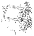
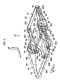
- FIG 1 and FIG 2 there is shown, in perspective views, the configuration of relevant portions of a rear seat 10 that serves as a vehicular seat pertaining to the embodiment of the present invention. Further, in FIG 3 and FIG. 4 , there is shown, in side views, the configuration of relevant portions of this rear seat 10.
- arrow FR represents a vehicle front direction
- arrow UP represents a vehicle up direction
- arrow W represents a vehicle width direction.
- the rear seat 10 pertaining to the embodiment of the present invention is a seat in a rearmost portion of an unillustrated automobile (e.g., a so-called van type or minivan type of automobile) and, as shown in FIG. 3 and FIG. 4 , is installed on the upper portion of a floor 14 (vehicle body floor) that is formed flatly overall. It will be noted that, in the present embodiment, the directionality of front, rear, left, right, up and down of the rear seat 10 coincides with the directionality of front, rear, left, right, up and down of the automobile in which this rear seat 10 is installed.
- This rear seat 10 includes a seat cushion 16 for seating a passenger and a seat back 18 that supports the back of a passenger who is seated on this seat cushion 16.
- the seat cushion 16 includes a cushion frame 20 that serves as a skeleton member that configures the skeleton of the seat cushion 16.
- the cushion frame 20 is disposed with a pair of left and right extension portions 20A and 20B that extend along the front-rear direction inside both width direction side portions of the seat cushion 16.
- the pair of extension portions 20A and 20B are formed in plate shapes and are disposed in a state where their plate thickness direction is along the vehicle width direction.
- the rear end portions of the pair of extension portions 20A and 20B are coupled together by a plate-shaped coupling portion 20C that extends along the vehicle width direction, and the cushion frame 20 is formed in a substantial U shape when seen from above.
- An elastically deformable cushion pad is attached via a cushion pan (both of which are not shown) to this cushion frame 20, and the surface of the cushion pad is covered by a surface material 22.
- the seat cushion 16 of the above-described configuration is coupled to the floor 14 via a link mechanism 24 and a pair of rails 26 (guide members) that configure a support mechanism, and the seat cushion 16 is configured to be movable between a use position (the position shown in FIG 1 and FIG. 3 ) where a passenger is capable of sitting on the seat cushion 16 and a storage position (the position shown in FIG. 2 and FIG. 4 ) that is set in back of this use position on the lower side (a position lower than the use position) of a deck board 25 that configures the floor of a cargo compartment 12 (it will be noted that, below, the space on the lower side of the deck board 25 will be called a storage compartment 31).
- the pair of rails 26 are for coupling the rear end portion of the seat cushion 16 to the floor 14 and are disposed on both the left and right sides of the storage compartment 31 (the rear lower side of the seat cushion 16 that has been disposed in the use position).
- These rails 26 include vertical walls 26A (one wall) that are respectively formed in plate shapes. These vertical walls 26A are formed so as to be long along the vehicle front-rear direction and are disposed so as to face the side portions of the seat cushion 16 in a state where the seat cushion 16 has been disposed in the storage position.
- Fixing pieces 26B extend from the lower end portions of the vertical walls 26A toward the opposite side of the seat cushion 16. These fixing pieces 26B are fastened to the floor 14 by unillustrated fasteners, whereby the rails 26 are attached to the floor 14.
- guide grooves 28 (long holes) that are formed in substantial crank shapes are formed in the vertical walls 26A.
- Each of the guide grooves 28 includes a first horizontal portion 28A that is disposed in the front end portion of the vertical wall 26A, a second horizontal portion 28B that is disposed in the rear end side of the vertical wall 26A and a slanted portion 28C that is disposed between the first horizontal portion 28A and the second horizontal portion 28B.
- the second horizontal portion 28B extends substantially horizontally with respect to the floor 14 in the vicinity of the floor 14, and the first horizontal portion 28A is disposed in a higher position than the second horizontal portion 28B and extends substantially horizontally with respect to the floor 14.
- the slanted portion 28C slants in a rearward descending state with respect to the floor 14.
- the rear end portion of the seat cushion 16 is coupled to the floor 14 via the rails 26.
- the moving direction of the rear end portion of the seat cushion 16 is guided as a result of the projections 30 moving along the guide grooves 28.
- the projections 30 are disposed in the first horizontal portions 28A and the rear end portion of the seat cushion 16 is away from the floor 14.
- the projections 30 move along the slanted portions 28C, whereby the rear end portion of the seat cushion 16 is lowered toward the floor 14 (see arrow A in FIG 3 ).
- the projections 30 enter the second horizontal portions 28B from the slanted portions 28C and are moved along the second horizontal portions 28B, the rear end portion of the seat cushion 16 is moved horizontally with respect to the floor 14.
- the projections 30 move along the slanted portions 28C, whereby the rear end portion of the seat cushion 16 is moved away (raised) from the floor 14. Then, when the projections 30 enter the first horizontal portions 28A from the slanted portions 28C and contact the inner peripheries of the front end portions of the first horizontal portions 28A, movement of the seat cushion 16 toward the front side of the vehicle is limited, and the seat cushion 16 is disposed in the use position (the state shown in FIG 1 and FIG 3 ).
- the aforementioned link mechanism 24 is for coupling the front end portion of the seat cushion 16 to the floor 14 and includes a fixing member 32 that is fixed to the floor 14. As shown in FIG. 1 and FIG 2 , the fixing member 32 is disposed with a body portion 32A that is formed in a plate shape that is long along the vehicle width direction, and this body portion 32A is fastened to the floor 14 by an unillustrated fastener. Plate-shaped coupling pieces 32B extend upward from both longitudinal direction end portions of the body portion 32A. A link member 34 is coupled to these coupling pieces 32B.
- the link member 34 is disposed with a pair of arm portions 34A that are formed in long plate shapes. One longitudinal direction end portion of each of these arm portions 34A is rotatably coupled to the coupling pieces 32B via a support rod. The ether longitudinal direction end portion of each of the pair of arm portions 34A is fixed in a state where a torque rod 34B (rod portion) formed in a pipe shape is passed therethrough, and the pair of arm portions 34A are coupled together by this torque rod 34B.
- One axial line direction end portion of the torque rod 34B is rotatably coupled to the front end portion of the one extension portion 20A of the cushion frame 20, and the other axial line direction end portion of the torque rod 34B is rotatably coupled to the front end portion of the other extension portion 20B.
- This torque rod 34B configures the skeleton of the seat cushion 16 together with the cushion frame 20.
- the link member 34 of the above-described configuration is configured to stand upright between the seat cushion 16 and the floor 14 and support the seat cushion 16 in the use position in a state where the seat cushion 16 has been disposed in the use position. Further, when the seat cushion 16 is moved from the use position to the storage position, the link member 34 is moved (rotated) toward the rear side of the vehicle together with the seat cushion 16, whereby the moving direction of the front end portion of the seat cushion 16 is guided (see arrow C in FIG 3 ).
- the front end portion of the seat cushion 16 is moved along the rotational locus of the torque rod 34B resulting from the link member 34, so the link member 34 is lowered toward the floor 14 as it collapses toward the rear side of the vehicle. Then, when the link member 34 completely collapses on the rear side of the fixing member 32 (when the link member 34 is disposed along the vehicle floor 14), the seat cushion 16 is disposed in the storage position (the state shown in FIG 2 and FIG. 4 ).
- the front end portion of the seat cushion 16 is raised as the link member 34 is stood upright toward the front side of the vehicle (see arrow D in FIG 4 ). Then, movement of the seat cushion 16 toward the front side of the vehicle is limited by the aforementioned rails 26 (guide grooves 28), whereby rotation of the link member 34 is limited and the seat cushion 16 is disposed in the use position (the state shown in FIG 1 and FIG 3 ).
- the rear seat 10 pertaining to the present embodiment includes a torsion spring 38 (urging member) that urges the seat cushion 16 toward the storage position and a holding mechanism that holds the seat cushion 16 in the use position.
- a torsion spring 38 urging member
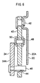
- the aforementioned holding mechanism includes a ratchet 40 that is formed in a long plate shape. As shown in FIG 6 , one longitudinal direction end portion (upper end portion) of this ratchet 40 is rotatably coupled to the one extension portion 20A of the cushion frame 20 via a support rod 42. Further, a cutout 44 that opens to one width direction side (rear side of the vehicle, one side in the rotational direction) of the ratchet 40 is formed in the other longitudinal direction end portion (lower end portion) of the ratchet 40. A circular column-shaped lock-use projecting portion 46 that is disposed on one of the arm portions 34A of the link member 34 fits into this cutout 44 in a state where the seat cushion 16 has been disposed in the use position (see FIG. 7 ).
- a tension coil spring 48 is disposed between the ratchet 40 and the one extension portion 20A, and this tension coil spring 48 urges the ratchet 40 toward the rear side of the vehicle (in the direction where the lock-use projecting portion 46 fits into the cutout 44). In a state where the lock-use projecting portion 46 is fitted into the cutout 44 in the ratchet 40, rotation of the link member 34 is limited; thus, the seat cushion 16 is held in the use position.
- a strap member 50 is coupled to the longitudinal direction intermediate portion of the ratchet 40, and when this strap member 50 is pulled toward the front side of the vehicle counter to the urging force of the tension coil spring 48, the ratchet 40 is rotated toward the front side of the vehicle such that the fitted state between the cutout 44 and the lock-use projecting portion 46 is released.
- the fitted state between the cutout 44 and the lock-use projecting portion 46 is released in this manner, rotation of the link member 34 toward the rear side of the vehicle becomes possible such that the seat cushion 16 can move to the storage position.
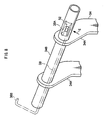
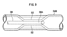
- the aforementioned torsion spring 38 is formed in a long rod shape by a spring material and, as shown in FIG 8 , one longitudinal direction end side and the longitudinal direction intermediate portion thereof are inserted (inset) inside the torque rod 34B of the link member 34.
- One longitudinal direction end portion of the torsion spring 38 is bent in a substantial U shape, and a one end side locking portion 38A for locking the torsion spring 38 to the torque rod 34B is formed.
- crush working is administered to a position of the torque rod 34B that corresponds to the one end side locking portion 38A such that a pair of crushed portions 52 are formed, and the one end side locking portion 38A is held between the pair of crushed portions 52.
- relative rotation of the one longitudinal direction end portion of the torsion spring 38 with respect to the torque rod 34B is limited.
- the other longitudinal direction end side of the torsion spring 38 that projects outside the torque rod 34B is bent in a substantial U shape, and another end side locking portion 38B is formed on the other longitudinal direction end portion of the torsion spring 38. This other end side locking portion 38B is locked to the other extension portion 20B of the cushion frame 20.
- This torsion spring 38 is twisted as a result of the link member 34 rotating relatively with respect to the cushion frame 20 when the seat cushion 16 is moved from the storage position to the use position; thus, the torsion spring 38 urges the seat cushion 16 that has been disposed in the use position toward the storage position.
- Plate-shaped coupling pieces 26C that extend upward from the end portions on the front end sides of the fixing pieces 26B on the opposite sides of the verticai walls 26A are disposed on the aforementioned rails 26.
- the coupling pieces 26C are coupled and fixed in a state where the lower end portions of coupling plates 54 (other wall, guide members) that are formed in plate shapes overlap them in the plate thickness direction.
- These coupling plates 54 are for supporting the aforementioned seat back 18 on the floor 14 and face the vertical walls 26A (one wall) along the left-right direction of the rear seat 10.
- the seat back 18 includes a back frame 56 that serves as a skeleton member that configures the skeleton of the seat back 18.
- the back frame 56 is disposed with a pair of plate-shaped side portions 56A and 56B, which are disposed inside both width direction side portions of the seat back 18 and extend in the height direction of the seat back 18, and a pipe-shaped upper portion 56C, which is disposed along the width direction of the seat back 18 inside the upper end portion of the seat back 18 and is coupled to the upper end portions of the pair of side portions 56A and 56B, such that the back frame 56 is formed in a substantial U shape when seen from the front.
- An elastically deformable back pad is attached via a back mat (both of which are not shown) to this back frame 56, and the surface of the back pad is covered by a surface material 58. It will be noted that a recessed portion 60 for preventing the seat cushion 16 from interfering with the seat back 18 when the seat cushion 16 moves between the use position and the storage position is formed in the lower end portion of the back pad.
- the lower end portions of the side portions 56A and 56B of the back frame 56 are respectively disposed between the coupling plates 54 and the vertical walls 26A on both the left and right sides of the seat back 18 and are rotatably coupled to the coupling plates 54 via support rods 62 (see FIG 5 ).
- a well-known reclining mechanism 64 is intervened between the one side portion 56A and one of the coupling plates 54, and the back frame 56 (the seat back 18) is supported on that coupling plate 54 via this reclining mechanism 64.
- a lever 66 is disposed in this reclining mechanism 64, and rotation of the back frame 56 (the seat back 18) with respect to the floor 14 is allowed only when this lever 66 is operated.
- the seat back 18 of the above-described configuration is configured to be rotatable between an upright position (the position shown in FIG 1 and FIG. 3 ) where the seat back 18 supports the back of a passenger seated on the seat cushion 16 that has been disposed in the use position and a forwardly collapsed position (the position shown in FIG. 2 and FIG 4 ) where the seat back 18 is disposed in line in front of the seat cushion 16 that has been moved to the storage position.
- the front end portion of the seat cushion 16 is inserted inside the recessed portion 60 in the seat back 18 such that the seat back 18 and the seat cushion 16 are stored continuously from front to back.
- the storage position of the seat cushion 16 is disposed on the lower side of the deck board 25 that configures the floor of the cargo compartment 12 as mentioned previously, and the back surface of the seat back 18 that has been disposed in the forwardly collapsed position is disposed in substantially the same height as the upper surface of the deck board 25 (see FIG. 4 ).
- a rotating board 68 that is formed in a plate shape is rotatably coupled to the front end portion of the deck board 25 (the end portion on the seat back 18 side) via a hinge 70.
- This rotating board 68 is disposed upright along the back surface of the seat back 18 in a state where the seat back 18 has been disposed in the upright position. Further, this rotating board 68 is urged toward the front side of the vehicle (toward the seat back 18) by an unillustrated urging member, and when the seat back 18 is rotated toward the front side of the vehicle (toward the forwardly collapsed position), the rotating board 68 is rotated toward the front side of the vehicle together with the seat back 18.
- this rotating board 68 is disposed so as to span the distance between the back surface of the seat back 18 and the deck board 25 in a state where the seat back 18 has been disposed in the forwardly collapsed position.
- the gap between the back surface of the seat back 18 and the deck board 25 is blocked off by the rotating board 68 such that a continuous floor surface is formed by the back surface of the seat back, the upper surface of the rotating board 68 and the upper surface of the deck board 25.
- the seat back 18 when the seat back 18 is rotated to the forwardly collapsed position in a state where the seat cushion 16 has been moved to the storage position, the seat back 18 is disposed in line in front of the seat cushion 16 (the seat back 18 and the seat cushion 16 are stored in parallel from front to back). Consequently, the seat back 18 and the seat cushion 16 can be thinly stored in the up-down direction of the vehicle. Moreover, the storage position of the seat cushion 16 is set on the rear lower side of the use position, so the space above the storage position.(the space of the cargo compartment 12 above the deck board 25) can be widely ensured.
- the link member 34 is disposed along the floor 14 in a state where the seat cushion 16 has been moved to the storage position. Consequently, a situation where the link member 34 becomes an obstacle in the stored state of the seat cushion 16 can be controlled.
- the torque rod 34B that is disposed on the one end side of the link member 34 configures the skeleton of the seat cushion 16 together with the cushion frame 20. Consequently, the structure of the cushion frame 20 can be simplified, and a reduction in the number of parts, a reduction in weight and a reduction in cost can be achieved.
- the seat cushion 16 is urged toward the storage position by the torsion spring 38, one longitudinal direction end side of which is locked to the torque rod 34B and the other longitudinal direction end side of which is locked to the cushion frame 20. Consequently, the seat cushion 16 can be urged toward the storage position by a simple configuration.
- the one longitudinal direction end side and the longitudinal direction intermediate portion of the torsion spring 38 are inserted (housed) inside the torque rod 34B, so the torsion spring 38 can be compactly installed.
- the projections 30 that are disposed on both the left and right sides of the rear end portion of the cushion frame 20 move along the guide grooves 28 in the rails 26 that are disposed on both the left and right sides of the seat cushion 16 and are attached to the floor 14, whereby the movement of the rear end portion of the seat cushion 16 is guided between the use position and the storage position.
- the locus of movement of the rear end portion of the seat cushion 16 can be set to an optimum locus of movement by appropriately setting and changing the shapes of the guide grooves 28.
- the rails 26 are disposed in the storage compartment 31 in which the seat cushion 16 is stored. Consequently, the rails 26 do not become an obstacle in the stored state of the seat cushion 16.
- the vertical walls 26A of the rails 26 and the coupling plates 54 face each other in the left-right direction, the guide grooves 28 that guide the movement of the seat cushion 16 are formed in the vertical walls 26A (one wall), and the seat back 18 is supported on the coupling plates 54 (other wall) via the reclining mechanism 64 that is disposed between the vertical walls 26A and the coupling plates 54 (between both walls). Consequently, an appropriate disposition where there is no danger of interfering while the seat cushion 16 and the seat back 18 are in the middle of moving can be realized with little space.
- the storage position of the seat cushion 16 is set on the lower side of the deck board 25 that configures the floor of the cargo compartment 12, and in a state where the seat back 18 has been disposed in the forwardly collapsed position (in a state where the cargo compartment 12 has been expanded), the floor of the cargo compartment is configured by the back surface of the seat back 18, the upper surface of the rotating board 68 and the upper surface of the deck board 25. Consequently, a situation where dirt or the like on cargo that is placed on the floor of the cargo compartment 12 adheres to the surfaces of the seat back 18 and the seat cushion 16 can be prevented or controlled.
- the rear seat 10 pertaining to the above-described embodiment has been given a configuration where the seat cushion 16 is moved to the storage position by the urging force of the torsion spring 38 (urging member), the present invention is not limited to this and the urging member may also be omitted. Further, the invention may also be given a configuration where the seat cushion is automatically moved between the use position and the storage position by the driving force of a motor or the like.
- the support mechanism that supports the seat cushion is configured to include the link member (member that rotates by the movement of the seat cushion), so by giving the invention a configuration where the driving force (rotating force) of a motor or the like is transmitted to the link member, the movement of the seat cushion can be easily automated.
- the present invention is not limited to this and may also be given a configuration where the torque rod 34B is omitted. In this case, the configuration becomes one where the pair of arm portions 34A of the link member 34 are rotatably coupled to the pair of extension portions 20A and 20B of the cushion frame 20.
- the rear seat 10 pertaining to the above-described embodiment has been given a configuration where part of the torsion spring 38 (urging member) is inset in the torque rod 34B of the link member 34, the present invention is not limited to this, and the disposition of the urging member can be appropriately set and changed.
- the present invention is not limited to this and may also be given a configuration where the moving direction of the rear end portion of the seat cushion 16 is guided by link members or rail-shaped members.
Landscapes
- Engineering & Computer Science (AREA)
- Aviation & Aerospace Engineering (AREA)
- Transportation (AREA)
- Mechanical Engineering (AREA)
- Seats For Vehicles (AREA)
Claims (5)
- Fahrzeugsitz mit:einem Sitzpolster (16) für einen Fahrgast, wobei das Sitzpolster einen Polsterrahmen aufweist, der als ein Gerüstelement dient;einem Stützmechanismus, der gestaltet ist, ein Verbindungselement (24) aufzuweisen, von dem ein Ende mittels eines Stababschnitts drehbar mit dem Sitzpolster (16) gekoppelt ist und von dem das andere Ende drehbar mit einem Fahrzeugboden (14) gekoppelt sein kann, und der das Sitzpolster (16) bezüglich des Fahrzeugbodens stützt, so dass das Sitzpolster (16) zwischen einer Gebrauchsposition, in der ein Fahrgast in der Lage ist, auf dem Sitzpolster (16) zu sitzen, und einer Aufbewahrungsposition bewegbar ist, die an einer heckseitigen unteren Seite der Gebrauchsposition festgelegt ist; undeiner Sitzlehne (18), die an dem Fahrzeugboden (14) gestützt werden kann, so dass die Sitzlehne (18) zwischen einer aufrechten Position, in der die Sitzlehne den Rücken eines Fahrgastes stützt, der auf dem Sitzpolster sitzt, das in die Gebrauchsposition angeordnet worden ist, und einer nach vorne zusammengeklappten Position drehbar ist, in der die Sitzlehne (18) auf eine Linie vor dem Sitzpolster (16) angeordnet ist, das in die Aufbewahrungsposition bewegt worden ist;einem Haltemechanismus (40), der das Sitzpolster (16) in der Gebrauchsposition hält und in der Lage ist, den Halt zu lösen; gekennzeichnet durchein drängendes Element (38), das das Sitzpolster (16) zu der Aufbewahrungsposition drängt, wobei ein Ende des drängenden Elements (38) in den Stababschnitt eingeführt und an dem Stababschnitt gesichert ist, und das andere Ende des drängenden Elements (38) an dem Polsterrahmen gesichert ist.
- Fahrzeugsitz nach Anspruch 1, wobei das Verbindungselement (24) in einem Zustand, in dem das Sitzpolster (16) in die Aufbewahrungsposition bewegt worden ist, entlang dem Fahrzeugboden (14) angeordnet ist.
- Fahrzeugsitz nach Anspruch 1 oder 2, wobei das eine Ende des Verbindungselements (24) an einem frontseitigen Endabschnitt des Sitzpolsters (16) gekoppelt ist, und der Stützmechanismus Vorsprünge (30), die an beiden Seiten, links und rechts, eines heckseitigen Endabschnitts des Sitzpolsters (16) angeordnet sind, und Führungselemente (28) aufweist, die an beiden Seiten, links und rechts, des Sitzpolsters angeordnet sind, an dem Fahrzeugboden angebracht werden können und in denen Führungsnuten (28) ausgebildet sind, in denen die Vorsprünge (30) hineinpassen, so dass die Vorsprünge (30) relativ bewegbar sind.
- Fahrzeugsitz nach Anspruch 3, wobei die Führungselemente (28) zwei Wände (26A, 26C) aufweisen, die einander von links nach rechts zugewandt sind, wobei die Führungsnuten (28) in einer Wand (26a) ausgebildet sind und die Sitzlehne an der anderen Wand (26C) über einen Neigungsmechanismus gestütz ist, der zwischen beiden Wänden angeordnet ist.
- Fahrzeugsitz nach einem der Ansprüche 1 bis 4, wobei die Aufbewahrungsposition an einer unteren Seite einer Abdeckplatte festgelegt ist, die einen Boden eines Frachtraums bildet.
Applications Claiming Priority (2)
| Application Number | Priority Date | Filing Date | Title |
|---|---|---|---|
| JP2007044655A JP4850750B2 (ja) | 2007-02-23 | 2007-02-23 | 車両用シート |
| PCT/JP2008/052845 WO2008102800A1 (ja) | 2007-02-23 | 2008-02-20 | 車両用シート |
Publications (3)
| Publication Number | Publication Date |
|---|---|
| EP2065251A1 EP2065251A1 (de) | 2009-06-03 |
| EP2065251A4 EP2065251A4 (de) | 2010-02-03 |
| EP2065251B1 true EP2065251B1 (de) | 2012-12-12 |
Family
ID=39710074
Family Applications (1)
| Application Number | Title | Priority Date | Filing Date |
|---|---|---|---|
| EP08711651A Active EP2065251B1 (de) | 2007-02-23 | 2008-02-20 | Fahrzeugsitz |
Country Status (6)
| Country | Link |
|---|---|
| US (1) | US8177279B2 (de) |
| EP (1) | EP2065251B1 (de) |
| JP (1) | JP4850750B2 (de) |
| CN (1) | CN101616821B (de) |
| AU (1) | AU2008218038B2 (de) |
| WO (1) | WO2008102800A1 (de) |
Families Citing this family (24)
| Publication number | Priority date | Publication date | Assignee | Title |
|---|---|---|---|---|
| US7878592B2 (en) * | 2007-03-14 | 2011-02-01 | Aisin Seiki Kabushiki Kaisha | Seat apparatus for vehicle |
| JP5298457B2 (ja) * | 2007-05-18 | 2013-09-25 | アイシン精機株式会社 | 車両用シート装置 |
| JP5119910B2 (ja) * | 2007-12-26 | 2013-01-16 | トヨタ紡織株式会社 | 車両用シート |
| JP5398336B2 (ja) | 2009-04-27 | 2014-01-29 | アイシン精機株式会社 | 車両用シートのロック装置 |
| JP5353537B2 (ja) * | 2009-08-03 | 2013-11-27 | トヨタ紡織株式会社 | 隙間カバー付き乗物用シート |
| JP5342961B2 (ja) * | 2009-08-18 | 2013-11-13 | トヨタ紡織株式会社 | ベルトバックル付き乗物用シート |
| JP5289233B2 (ja) * | 2009-08-21 | 2013-09-11 | アイシン精機株式会社 | 車両用シート |
| JP5429539B2 (ja) | 2009-08-21 | 2014-02-26 | アイシン精機株式会社 | シート状態変更装置 |
| JP5448642B2 (ja) * | 2009-08-21 | 2014-03-19 | アイシン精機株式会社 | 電動格納車両シートのロック装置 |
| JP5418827B2 (ja) * | 2009-08-21 | 2014-02-19 | アイシン精機株式会社 | シート制御機構 |
| JP5448155B2 (ja) * | 2009-08-21 | 2014-03-19 | アイシン精機株式会社 | シート姿勢変更装置 |
| JP5291573B2 (ja) * | 2009-08-21 | 2013-09-18 | アイシン精機株式会社 | シート状態変更装置 |
| JP5446588B2 (ja) * | 2009-08-21 | 2014-03-19 | トヨタ紡織株式会社 | 車両用シート装置 |
| JP5527681B2 (ja) * | 2009-08-21 | 2014-06-18 | アイシン精機株式会社 | シート状態変更装置 |
| JP5291574B2 (ja) * | 2009-08-21 | 2013-09-18 | アイシン精機株式会社 | シート姿勢変更装置 |
| JP5301392B2 (ja) * | 2009-08-21 | 2013-09-25 | アイシン精機株式会社 | 車両用シート装置 |
| JP5418826B2 (ja) * | 2009-08-21 | 2014-02-19 | アイシン精機株式会社 | シート状態変更装置 |
| US8550549B2 (en) | 2010-08-30 | 2013-10-08 | Honda Motor Co., Ltd. | Seat flap for a vehicle seat |
| US8398164B2 (en) | 2010-08-30 | 2013-03-19 | Honda Motor Co., Ltd. | Seat flap for a vehicle seat |
| JP5679882B2 (ja) * | 2011-03-31 | 2015-03-04 | 富士機工株式会社 | シートの固定装置 |
| WO2017022675A1 (ja) * | 2015-07-31 | 2017-02-09 | テイ・エス テック株式会社 | 車両用シート |
| US10632873B2 (en) * | 2018-04-04 | 2020-04-28 | Ford Global Technologies, Llc | Seat structure dual motion recliner pivot mechanism |
| JP6739465B2 (ja) * | 2018-04-18 | 2020-08-12 | 本田技研工業株式会社 | 車両用シート装置 |
| CN111204264A (zh) * | 2018-11-22 | 2020-05-29 | 博泽科堡汽车零件有限公司 | 车辆座椅、其吸能装置和包括车辆座椅的车辆 |
Family Cites Families (25)
| Publication number | Priority date | Publication date | Assignee | Title |
|---|---|---|---|---|
| US3202453A (en) * | 1963-07-09 | 1965-08-24 | Ford Motor Co | Retractable seat |
| US3171682A (en) * | 1963-09-23 | 1965-03-02 | Gen Motors Corp | Folding vehicle seats |
| FR2411105A1 (fr) * | 1977-12-09 | 1979-07-06 | Peugeot | Siege transformable perfectionne pour vehicules automobiles |
| JPS6054632A (ja) * | 1983-09-07 | 1985-03-29 | 大和鉄工株式会社 | 製麺用ミキサ |
| JPS6054632U (ja) * | 1983-09-24 | 1985-04-17 | 池田物産株式会社 | 座席装置 |
| US6183033B1 (en) * | 1998-03-31 | 2001-02-06 | Ikeda Bussan Co., Ltd. | Automobile seat |
| JP3926485B2 (ja) * | 1998-07-27 | 2007-06-06 | ジョンソン コントロールズ オートモーティブ システムズ株式会社 | 自動車のフラット化シート構造 |
| JP2000343994A (ja) * | 1999-06-02 | 2000-12-12 | Takashimaya Nippatsu Kogyo Co Ltd | 自動車用リヤシート |
| JP2000351345A (ja) | 1999-06-09 | 2000-12-19 | Ikeda Bussan Co Ltd | 車両のフラット化反転シート構造 |
| JP4024428B2 (ja) * | 1999-06-16 | 2007-12-19 | ジョンソン コントロールズ オートモーティブ システムズ株式会社 | 車両のフラット化シート構造 |
| GB2356557B (en) * | 1999-11-26 | 2003-12-17 | Autoliv Dev | Improvements in or relating to a vehicle seat unit |
| FR2804072B1 (fr) * | 2000-01-26 | 2002-04-19 | Peugeot Citroen Automobiles Sa | Siege pliant a demies-assises pour vehicule automobile |
| JP4666724B2 (ja) * | 2000-07-10 | 2011-04-06 | 株式会社デルタツーリング | 折り畳み式シート |
| FR2826321B1 (fr) | 2001-06-21 | 2003-09-26 | Faurecia Sieges Automobile | Siege de vehicule et vehicule equipe d'un tel siege |
| GB0120250D0 (en) * | 2001-08-21 | 2001-10-10 | Ford Global Tech Inc | Vehicle seating |
| JP3662873B2 (ja) * | 2001-10-16 | 2005-06-22 | 本田技研工業株式会社 | 車両用シート |
| EP1316468A1 (de) | 2001-11-28 | 2003-06-04 | Ford Global Technologies, Inc. | Sitzanordnung |
| DE10307149A1 (de) * | 2003-02-20 | 2004-09-16 | Deere & Company, Moline | Klappbarer Fahrzeugsitz |
| JP2004330915A (ja) | 2003-05-08 | 2004-11-25 | Daihatsu Motor Co Ltd | 車両のシート構造 |
| JP2004359158A (ja) * | 2003-06-06 | 2004-12-24 | Toyota Motor Corp | 車両用シート格納構造 |
| DE10349911A1 (de) | 2003-10-25 | 2005-06-16 | Dr.Ing.H.C. F. Porsche Ag | Fahrzeugsitz |
| US7188883B2 (en) * | 2005-01-07 | 2007-03-13 | Ford Global Technologies, Llc | Collapsible seat assembly |
| DE102005020334A1 (de) | 2005-04-27 | 2006-11-02 | Sitech Sitztechnik Gmbh | Mechanische oder elektrische Sitzverlagerung in Abhängigkeit der Lehnenklappung |
| FR2887826B1 (fr) | 2005-06-30 | 2007-08-10 | Renault Sas | Siege apte a etre monte sur une structure de support |
| JP5298457B2 (ja) | 2007-05-18 | 2013-09-25 | アイシン精機株式会社 | 車両用シート装置 |
-
2007
- 2007-02-23 JP JP2007044655A patent/JP4850750B2/ja active Active
-
2008
- 2008-02-20 CN CN200880005761.9A patent/CN101616821B/zh active Active
- 2008-02-20 EP EP08711651A patent/EP2065251B1/de active Active
- 2008-02-20 AU AU2008218038A patent/AU2008218038B2/en not_active Ceased
- 2008-02-20 US US12/443,379 patent/US8177279B2/en active Active
- 2008-02-20 WO PCT/JP2008/052845 patent/WO2008102800A1/ja active Application Filing
Also Published As
| Publication number | Publication date |
|---|---|
| AU2008218038A1 (en) | 2008-08-28 |
| CN101616821A (zh) | 2009-12-30 |
| EP2065251A4 (de) | 2010-02-03 |
| AU2008218038B2 (en) | 2011-01-27 |
| US20100019526A1 (en) | 2010-01-28 |
| WO2008102800A1 (ja) | 2008-08-28 |
| EP2065251A1 (de) | 2009-06-03 |
| JP2008207636A (ja) | 2008-09-11 |
| US8177279B2 (en) | 2012-05-15 |
| JP4850750B2 (ja) | 2012-01-11 |
| CN101616821B (zh) | 2013-04-24 |
Similar Documents
| Publication | Publication Date | Title |
|---|---|---|
| EP2065251B1 (de) | Fahrzeugsitz | |
| EP1697161B1 (de) | Fahrzeugsitzanordnung und bodenschiene für laterales hin- und herbewegen eines sitzes | |
| US6070934A (en) | Folding seat mounting apparatus | |
| US7762604B1 (en) | Vehicle seating arrangement | |
| JP3400066B2 (ja) | 自動車のシートスライド装置 | |
| EP0881970B1 (de) | Automatischer Höhen-und Neigungsverstellmechanismus einer Rückenlehne | |
| EP2540556B1 (de) | Fahrzeugsitz | |
| US20100295353A1 (en) | Fold and kneel seat assembly with stand up mechanism | |
| EP2322381B1 (de) | Sitzvorrichtung für ein Fahrzeug | |
| US20120267930A1 (en) | Seating apparatus adjustment system | |
| CA2706460C (en) | Manual retracting head restraint | |
| US6290292B1 (en) | Seat back structure of hinged vehicle seat | |
| JP2003312340A (ja) | 自動車用シート | |
| JP6547586B2 (ja) | 乗り物用シート | |
| WO2005039921A1 (en) | Vehicle child seat assembly | |
| JP5507529B2 (ja) | 車両用荷室内構造 | |
| JP7393629B2 (ja) | 乗物用シート | |
| JP7389329B2 (ja) | 乗物用シート | |
| JP5094105B2 (ja) | 自動車のシート装置 | |
| JP2004009877A (ja) | 車両のシートのスライド装置 | |
| JP4380417B2 (ja) | 車両用シート装置 | |
| KR20230082382A (ko) | 시트프레임 | |
| JP2004017703A (ja) | 車両のシートのスライド装置 | |
| JPH11342778A (ja) | 自動車の後部座席 | |
| JP2004009876A (ja) | 車両のシートのスライド装置 |
Legal Events
| Date | Code | Title | Description |
|---|---|---|---|
| PUAI | Public reference made under article 153(3) epc to a published international application that has entered the european phase |
Free format text: ORIGINAL CODE: 0009012 |
|
| 17P | Request for examination filed |
Effective date: 20090401 |
|
| AK | Designated contracting states |
Kind code of ref document: A1 Designated state(s): AT BE BG CH CY CZ DE DK EE ES FI FR GB GR HR HU IE IS IT LI LT LU LV MC MT NL NO PL PT RO SE SI SK TR |
|
| A4 | Supplementary search report drawn up and despatched |
Effective date: 20100107 |
|
| RIC1 | Information provided on ipc code assigned before grant |
Ipc: B60N 2/30 20060101ALI20110712BHEP Ipc: B60N 2/36 20060101AFI20110712BHEP |
|
| 17Q | First examination report despatched |
Effective date: 20110727 |
|
| GRAP | Despatch of communication of intention to grant a patent |
Free format text: ORIGINAL CODE: EPIDOSNIGR1 |
|
| DAX | Request for extension of the european patent (deleted) | ||
| GRAS | Grant fee paid |
Free format text: ORIGINAL CODE: EPIDOSNIGR3 |
|
| GRAA | (expected) grant |
Free format text: ORIGINAL CODE: 0009210 |
|
| AK | Designated contracting states |
Kind code of ref document: B1 Designated state(s): AT BE BG CH CY CZ DE DK EE ES FI FR GB GR HR HU IE IS IT LI LT LU LV MC MT NL NO PL PT RO SE SI SK TR |
|
| RBV | Designated contracting states (corrected) |
Designated state(s): AT BE BG CH CY CZ DE DK EE ES FI FR GB GR HR HU IE IS IT LI LT LU LV MC MT NL NO PL PT RO SE SI SK TR |
|
| REG | Reference to a national code |
Ref country code: GB Ref legal event code: FG4D |
|
| REG | Reference to a national code |
Ref country code: CH Ref legal event code: EP |
|
| REG | Reference to a national code |
Ref country code: AT Ref legal event code: REF Ref document number: 588164 Country of ref document: AT Kind code of ref document: T Effective date: 20121215 |
|
| REG | Reference to a national code |
Ref country code: IE Ref legal event code: FG4D |
|
| REG | Reference to a national code |
Ref country code: DE Ref legal event code: R096 Ref document number: 602008020774 Country of ref document: DE Effective date: 20130207 |
|
| RAP2 | Party data changed (patent owner data changed or rights of a patent transferred) |
Owner name: AISIN SEIKI KABUSHIKI KAISHA Owner name: TOYOTA JIDOSHA KABUSHIKI KAISHA |
|
| PG25 | Lapsed in a contracting state [announced via postgrant information from national office to epo] |
Ref country code: HR Free format text: LAPSE BECAUSE OF FAILURE TO SUBMIT A TRANSLATION OF THE DESCRIPTION OR TO PAY THE FEE WITHIN THE PRESCRIBED TIME-LIMIT Effective date: 20121212 Ref country code: ES Free format text: LAPSE BECAUSE OF FAILURE TO SUBMIT A TRANSLATION OF THE DESCRIPTION OR TO PAY THE FEE WITHIN THE PRESCRIBED TIME-LIMIT Effective date: 20130323 Ref country code: FI Free format text: LAPSE BECAUSE OF FAILURE TO SUBMIT A TRANSLATION OF THE DESCRIPTION OR TO PAY THE FEE WITHIN THE PRESCRIBED TIME-LIMIT Effective date: 20121212 Ref country code: NO Free format text: LAPSE BECAUSE OF FAILURE TO SUBMIT A TRANSLATION OF THE DESCRIPTION OR TO PAY THE FEE WITHIN THE PRESCRIBED TIME-LIMIT Effective date: 20130312 Ref country code: SE Free format text: LAPSE BECAUSE OF FAILURE TO SUBMIT A TRANSLATION OF THE DESCRIPTION OR TO PAY THE FEE WITHIN THE PRESCRIBED TIME-LIMIT Effective date: 20121212 Ref country code: LT Free format text: LAPSE BECAUSE OF FAILURE TO SUBMIT A TRANSLATION OF THE DESCRIPTION OR TO PAY THE FEE WITHIN THE PRESCRIBED TIME-LIMIT Effective date: 20121212 |
|
| REG | Reference to a national code |
Ref country code: NL Ref legal event code: VDEP Effective date: 20121212 |
|
| REG | Reference to a national code |
Ref country code: AT Ref legal event code: MK05 Ref document number: 588164 Country of ref document: AT Kind code of ref document: T Effective date: 20121212 |
|
| REG | Reference to a national code |
Ref country code: LT Ref legal event code: MG4D |
|
| PG25 | Lapsed in a contracting state [announced via postgrant information from national office to epo] |
Ref country code: SI Free format text: LAPSE BECAUSE OF FAILURE TO SUBMIT A TRANSLATION OF THE DESCRIPTION OR TO PAY THE FEE WITHIN THE PRESCRIBED TIME-LIMIT Effective date: 20121212 Ref country code: GR Free format text: LAPSE BECAUSE OF FAILURE TO SUBMIT A TRANSLATION OF THE DESCRIPTION OR TO PAY THE FEE WITHIN THE PRESCRIBED TIME-LIMIT Effective date: 20130313 Ref country code: LV Free format text: LAPSE BECAUSE OF FAILURE TO SUBMIT A TRANSLATION OF THE DESCRIPTION OR TO PAY THE FEE WITHIN THE PRESCRIBED TIME-LIMIT Effective date: 20121212 |
|
| PG25 | Lapsed in a contracting state [announced via postgrant information from national office to epo] |
Ref country code: AT Free format text: LAPSE BECAUSE OF FAILURE TO SUBMIT A TRANSLATION OF THE DESCRIPTION OR TO PAY THE FEE WITHIN THE PRESCRIBED TIME-LIMIT Effective date: 20121212 Ref country code: BE Free format text: LAPSE BECAUSE OF FAILURE TO SUBMIT A TRANSLATION OF THE DESCRIPTION OR TO PAY THE FEE WITHIN THE PRESCRIBED TIME-LIMIT Effective date: 20121212 Ref country code: IS Free format text: LAPSE BECAUSE OF FAILURE TO SUBMIT A TRANSLATION OF THE DESCRIPTION OR TO PAY THE FEE WITHIN THE PRESCRIBED TIME-LIMIT Effective date: 20130412 Ref country code: SK Free format text: LAPSE BECAUSE OF FAILURE TO SUBMIT A TRANSLATION OF THE DESCRIPTION OR TO PAY THE FEE WITHIN THE PRESCRIBED TIME-LIMIT Effective date: 20121212 Ref country code: EE Free format text: LAPSE BECAUSE OF FAILURE TO SUBMIT A TRANSLATION OF THE DESCRIPTION OR TO PAY THE FEE WITHIN THE PRESCRIBED TIME-LIMIT Effective date: 20121212 Ref country code: BG Free format text: LAPSE BECAUSE OF FAILURE TO SUBMIT A TRANSLATION OF THE DESCRIPTION OR TO PAY THE FEE WITHIN THE PRESCRIBED TIME-LIMIT Effective date: 20130312 Ref country code: CZ Free format text: LAPSE BECAUSE OF FAILURE TO SUBMIT A TRANSLATION OF THE DESCRIPTION OR TO PAY THE FEE WITHIN THE PRESCRIBED TIME-LIMIT Effective date: 20121212 |
|
| PG25 | Lapsed in a contracting state [announced via postgrant information from national office to epo] |
Ref country code: RO Free format text: LAPSE BECAUSE OF FAILURE TO SUBMIT A TRANSLATION OF THE DESCRIPTION OR TO PAY THE FEE WITHIN THE PRESCRIBED TIME-LIMIT Effective date: 20121212 Ref country code: NL Free format text: LAPSE BECAUSE OF FAILURE TO SUBMIT A TRANSLATION OF THE DESCRIPTION OR TO PAY THE FEE WITHIN THE PRESCRIBED TIME-LIMIT Effective date: 20121212 Ref country code: PT Free format text: LAPSE BECAUSE OF FAILURE TO SUBMIT A TRANSLATION OF THE DESCRIPTION OR TO PAY THE FEE WITHIN THE PRESCRIBED TIME-LIMIT Effective date: 20130412 Ref country code: PL Free format text: LAPSE BECAUSE OF FAILURE TO SUBMIT A TRANSLATION OF THE DESCRIPTION OR TO PAY THE FEE WITHIN THE PRESCRIBED TIME-LIMIT Effective date: 20121212 |
|
| PG25 | Lapsed in a contracting state [announced via postgrant information from national office to epo] |
Ref country code: MC Free format text: LAPSE BECAUSE OF NON-PAYMENT OF DUE FEES Effective date: 20130228 |
|
| REG | Reference to a national code |
Ref country code: CH Ref legal event code: PL |
|
| PLBE | No opposition filed within time limit |
Free format text: ORIGINAL CODE: 0009261 |
|
| STAA | Information on the status of an ep patent application or granted ep patent |
Free format text: STATUS: NO OPPOSITION FILED WITHIN TIME LIMIT |
|
| PG25 | Lapsed in a contracting state [announced via postgrant information from national office to epo] |
Ref country code: DK Free format text: LAPSE BECAUSE OF FAILURE TO SUBMIT A TRANSLATION OF THE DESCRIPTION OR TO PAY THE FEE WITHIN THE PRESCRIBED TIME-LIMIT Effective date: 20121212 Ref country code: CH Free format text: LAPSE BECAUSE OF NON-PAYMENT OF DUE FEES Effective date: 20130228 Ref country code: LI Free format text: LAPSE BECAUSE OF NON-PAYMENT OF DUE FEES Effective date: 20130228 |
|
| 26N | No opposition filed |
Effective date: 20130913 |
|
| PG25 | Lapsed in a contracting state [announced via postgrant information from national office to epo] |
Ref country code: CY Free format text: LAPSE BECAUSE OF FAILURE TO SUBMIT A TRANSLATION OF THE DESCRIPTION OR TO PAY THE FEE WITHIN THE PRESCRIBED TIME-LIMIT Effective date: 20121212 |
|
| REG | Reference to a national code |
Ref country code: IE Ref legal event code: MM4A |
|
| PG25 | Lapsed in a contracting state [announced via postgrant information from national office to epo] |
Ref country code: IT Free format text: LAPSE BECAUSE OF FAILURE TO SUBMIT A TRANSLATION OF THE DESCRIPTION OR TO PAY THE FEE WITHIN THE PRESCRIBED TIME-LIMIT Effective date: 20121212 |
|
| REG | Reference to a national code |
Ref country code: DE Ref legal event code: R097 Ref document number: 602008020774 Country of ref document: DE Effective date: 20130913 |
|
| PG25 | Lapsed in a contracting state [announced via postgrant information from national office to epo] |
Ref country code: IE Free format text: LAPSE BECAUSE OF NON-PAYMENT OF DUE FEES Effective date: 20130220 |
|
| PG25 | Lapsed in a contracting state [announced via postgrant information from national office to epo] |
Ref country code: MT Free format text: LAPSE BECAUSE OF FAILURE TO SUBMIT A TRANSLATION OF THE DESCRIPTION OR TO PAY THE FEE WITHIN THE PRESCRIBED TIME-LIMIT Effective date: 20121212 |
|
| PG25 | Lapsed in a contracting state [announced via postgrant information from national office to epo] |
Ref country code: TR Free format text: LAPSE BECAUSE OF FAILURE TO SUBMIT A TRANSLATION OF THE DESCRIPTION OR TO PAY THE FEE WITHIN THE PRESCRIBED TIME-LIMIT Effective date: 20121212 |
|
| PG25 | Lapsed in a contracting state [announced via postgrant information from national office to epo] |
Ref country code: HU Free format text: LAPSE BECAUSE OF FAILURE TO SUBMIT A TRANSLATION OF THE DESCRIPTION OR TO PAY THE FEE WITHIN THE PRESCRIBED TIME-LIMIT; INVALID AB INITIO Effective date: 20080220 Ref country code: LU Free format text: LAPSE BECAUSE OF NON-PAYMENT OF DUE FEES Effective date: 20130220 |
|
| REG | Reference to a national code |
Ref country code: DE Ref legal event code: R084 Ref document number: 602008020774 Country of ref document: DE |
|
| REG | Reference to a national code |
Ref country code: FR Ref legal event code: PLFP Year of fee payment: 9 |
|
| REG | Reference to a national code |
Ref country code: FR Ref legal event code: PLFP Year of fee payment: 10 |
|
| REG | Reference to a national code |
Ref country code: FR Ref legal event code: PLFP Year of fee payment: 11 |
|
| REG | Reference to a national code |
Ref country code: GB Ref legal event code: 746 Effective date: 20180530 |
|
| REG | Reference to a national code |
Ref country code: DE Ref legal event code: R081 Ref document number: 602008020774 Country of ref document: DE Owner name: TOYOTA JIDOSHA KABUSHIKI KAISHA, TOYOTA-SHI, JP Free format text: FORMER OWNERS: AISIN SEIKI KABUSHIKI KAISHA, KARIYA-SHI, AICHI-KEN, JP; TOYOTA JIDOSHA KABUSHIKI KAISHA, TOYOTA-SHI, AICHI-KEN, JP Ref country code: DE Ref legal event code: R081 Ref document number: 602008020774 Country of ref document: DE Owner name: TOYOTA BOSHOKU KABUSHIKI KAISHA, KARIYA-SHI, JP Free format text: FORMER OWNERS: AISIN SEIKI KABUSHIKI KAISHA, KARIYA-SHI, AICHI-KEN, JP; TOYOTA JIDOSHA KABUSHIKI KAISHA, TOYOTA-SHI, AICHI-KEN, JP |
|
| REG | Reference to a national code |
Ref country code: GB Ref legal event code: 732E Free format text: REGISTERED BETWEEN 20231116 AND 20231122 |
|
| PGFP | Annual fee paid to national office [announced via postgrant information from national office to epo] |
Ref country code: DE Payment date: 20231228 Year of fee payment: 17 Ref country code: GB Payment date: 20240108 Year of fee payment: 17 |
|
| PGFP | Annual fee paid to national office [announced via postgrant information from national office to epo] |
Ref country code: FR Payment date: 20240103 Year of fee payment: 17 |