EP2053437B1 - Movable body driving mechanism - Google Patents
Movable body driving mechanism Download PDFInfo
- Publication number
- EP2053437B1 EP2053437B1 EP08151175A EP08151175A EP2053437B1 EP 2053437 B1 EP2053437 B1 EP 2053437B1 EP 08151175 A EP08151175 A EP 08151175A EP 08151175 A EP08151175 A EP 08151175A EP 2053437 B1 EP2053437 B1 EP 2053437B1
- Authority
- EP
- European Patent Office
- Prior art keywords
- region
- cam
- frame
- cam follower
- lateral surface
- Prior art date
- Legal status (The legal status is an assumption and is not a legal conclusion. Google has not performed a legal analysis and makes no representation as to the accuracy of the status listed.)
- Active
Links
- 238000003384 imaging method Methods 0.000 claims description 35
- 230000007423 decrease Effects 0.000 claims description 2
- 238000004519 manufacturing process Methods 0.000 abstract description 6
- 230000003287 optical effect Effects 0.000 description 20
- 238000005266 casting Methods 0.000 description 5
- 230000004888 barrier function Effects 0.000 description 4
- 230000002093 peripheral effect Effects 0.000 description 2
- 230000000694 effects Effects 0.000 description 1
- 238000000605 extraction Methods 0.000 description 1
- 230000002452 interceptive effect Effects 0.000 description 1
Images


Classifications
-
- G—PHYSICS
- G02—OPTICS
- G02B—OPTICAL ELEMENTS, SYSTEMS OR APPARATUS
- G02B7/00—Mountings, adjusting means, or light-tight connections, for optical elements
- G02B7/02—Mountings, adjusting means, or light-tight connections, for optical elements for lenses
- G02B7/04—Mountings, adjusting means, or light-tight connections, for optical elements for lenses with mechanism for focusing or varying magnification
- G02B7/10—Mountings, adjusting means, or light-tight connections, for optical elements for lenses with mechanism for focusing or varying magnification by relative axial movement of several lenses, e.g. of varifocal objective lens
- G02B7/102—Mountings, adjusting means, or light-tight connections, for optical elements for lenses with mechanism for focusing or varying magnification by relative axial movement of several lenses, e.g. of varifocal objective lens controlled by a microcomputer
-
- G—PHYSICS
- G02—OPTICS
- G02B—OPTICAL ELEMENTS, SYSTEMS OR APPARATUS
- G02B7/00—Mountings, adjusting means, or light-tight connections, for optical elements
- G02B7/02—Mountings, adjusting means, or light-tight connections, for optical elements for lenses
- G02B7/04—Mountings, adjusting means, or light-tight connections, for optical elements for lenses with mechanism for focusing or varying magnification
- G02B7/08—Mountings, adjusting means, or light-tight connections, for optical elements for lenses with mechanism for focusing or varying magnification adapted to co-operate with a remote control mechanism
-
- G—PHYSICS
- G03—PHOTOGRAPHY; CINEMATOGRAPHY; ANALOGOUS TECHNIQUES USING WAVES OTHER THAN OPTICAL WAVES; ELECTROGRAPHY; HOLOGRAPHY
- G03B—APPARATUS OR ARRANGEMENTS FOR TAKING PHOTOGRAPHS OR FOR PROJECTING OR VIEWING THEM; APPARATUS OR ARRANGEMENTS EMPLOYING ANALOGOUS TECHNIQUES USING WAVES OTHER THAN OPTICAL WAVES; ACCESSORIES THEREFOR
- G03B11/00—Filters or other obturators specially adapted for photographic purposes
- G03B11/04—Hoods or caps for eliminating unwanted light from lenses, viewfinders or focusing aids
- G03B11/043—Protective lens closures or lens caps built into cameras
-
- Y—GENERAL TAGGING OF NEW TECHNOLOGICAL DEVELOPMENTS; GENERAL TAGGING OF CROSS-SECTIONAL TECHNOLOGIES SPANNING OVER SEVERAL SECTIONS OF THE IPC; TECHNICAL SUBJECTS COVERED BY FORMER USPC CROSS-REFERENCE ART COLLECTIONS [XRACs] AND DIGESTS
- Y10—TECHNICAL SUBJECTS COVERED BY FORMER USPC
- Y10T—TECHNICAL SUBJECTS COVERED BY FORMER US CLASSIFICATION
- Y10T74/00—Machine element or mechanism
- Y10T74/16—Alternating-motion driven device with means during operation to adjust stroke
- Y10T74/1625—Stroke adjustable to zero and/or reversible in phasing
- Y10T74/1683—Cam and follower drive
Definitions
- the present invention relates to an imaging apparatus.
- the present invention relates to an imaging apparatus including a movable body driving mechanism capable of expanding and retracting a movable body by cam driving.
- This movable body driving mechanism is applicable to a lens barrel or the like.
- a lens and a barrel mounted in an imaging apparatus such as a digital camera or a video camera can be moved along an optical axis direction by a cam mechanism formed in the barrel.
- an imaging apparatus in order to obtain a high quality optical image, it is necessary to move the lens with high accuracy and restrict the lens position.
- JP 5(1993 )- 29013 U discloses a configuration including a biasing means for biasing a cam follower toward a cam groove, in which a tip portion of the cam follower is made to contact an inclined surface of the cam groove constantly, thus avoiding the looseness of a lens frame.
- a lens barrel according to EP 1 033 599 A1 includes a cam tube having a female helicoid and a cam formed in an inner wall thereof, a first tube which holds a lens and has a male helicoid formed on an outer wall thereof to engage the female helicoid, the first tube being arranged to be moved in an optical axis direction by rotation of the cam tube, and a lens holding member which holds a lens and has a cam pin provided thereon for engaging the cam of the cam tube, the lens holding member being arranged to be moved in the optical axis direction by a cam action of rotation of the cam tube, wherein the female helicoid and the cam of the cam tube respectively have loci which are continuous and uninterrupted without interfering with each other.
- the imaging apparatus according to the present invention is defined in claim 1.
- a lateral surface of the cam follower can be made to contact a lateral surface of the cam groove constantly, thus achieving the cam driving without looseness. Also, since the biasing means or the like is not needed, it is possible both to simplify the configuration and to reduce the number of manufacturing steps.
- FIG. 1 illustrates an example of an apparatus including a movable body driving mechanism in the present embodiment.
- the apparatus shown in FIG. 1 is an imaging apparatus mounted in a digital camera.
- An imaging apparatus 1 includes various lenses such as a zoom lens and a focus lens, an imaging device that converts incident light into an electric signal and outputs this signal, etc. It should be noted that the imaging apparatus illustrated in the present embodiment merely is an example and can be mounted in not only the digital camera but also a video camera or the like.
- a fixed frame 10 a drive frame 20 and a first group unit 40 are arranged at coaxial positions. Further, a gear 11 is disposed near the fixed frame 10. The gear 11 is driven rotationally by a driving means such as a motor.
- the drive frame 20 and the first group unit 40 are configured to be moved in a direction indicated by an arrow A by rotating the gear 11 in a direction indicated by an arrow C and moved in a direction indicated by an arrow B by rotating the gear 11 in a direction indicated by an arrow D.
- FIG. 1 shows the imaging apparatus 1 in the state where the drive frame 20 and the first group unit 40 are received in the fixed frame 10 (in the following, referred to as a collapsed state), and the drive frame 20 and the first group unit 40 can be expanded in the direction indicated by the arrow A by rotating the gear 11. Also, an end face of the first group unit 40 is provided with a plate-like lens barrier 41. The lens barrier 41 can open or close an opening 42 of the first group unit 40.
- FIG. 2 is an exploded perspective view showing individual units constituting the imaging apparatus 1.
- the imaging apparatus 1 includes the fixed frame 10, the drive frame 20, a rectilinear frame 30, the first group unit 40, a second group unit 50 and a base 60.
- an outer peripheral surface of a cylindrical portion in substantially cylindrical members such as the fixed frame 10, the drive frame 20 and the rectilinear frame 30 is referred to as an "outer surface,” and an inner peripheral surface of the cylindrical portion therein is referred to as an "inner surface.”
- the inner surface of the fixed frame 10 is provided with cam grooves 12.
- the fixed frame 10 is fixed to a chassis (not shown) of the imaging apparatus 1 together with the base 60. It is preferable to provide a plurality of the cam grooves 12. In the present embodiment, three cam grooves 12 are provided. Further, the inner surface of the fixed frame 10 is provided with a rectilinear groove 13 substantially in parallel with an optical axis direction.
- the drive frame 20 is disposed inside the fixed frame 10. Also, the drive frame 20 is provided in such a manner as to be rotatable in a circumferential direction and movable in the optical axis direction. The drive frame 20 is movable between a position at which it is received in the fixed frame 10 and a position at which it partially protrudes in the optical axis direction beyond the fixed frame 10. Additionally, the outer surface of the drive frame 20 is provided with cam followers 22. It is preferable to provide a plurality of the cam followers 22. In the present embodiment, the number of the cam followers 22 is three, which is the same as the number of the cam grooves 12. The cam followers 22 are fitted movably in the cam grooves 12 formed in the fixed frame 10.
- the inner surface of the drive frame 20 is provided with a plurality of cam grooves 23.
- the outer surface of the drive frame 20 is provided with a rack 21 along the circumferential direction. The rack 21 is in engagement with the gear 11 when the drive frame 20 is attached to the fixed frame 10. In this way, by rotating the gear 11 in the direction indicated by the arrow C or the arrow D, it is possible to rotate the drive frame 20 in a direction indicated by an arrow E or an arrow F.
- the rectilinear frame 30 is disposed inside the drive frame 20. Also, the rectilinear frame 30 is provided in such a manner as to be rotatable in the circumferential direction. Further, the rectilinear frame 30 is provided so as to move together with the drive frame 20 when the drive frame 20 moves in the direction indicated by the arrow A or the arrow B (see FIG. 1 ). Moreover, a plurality of elongated holes 31 are formed in the cylindrical portion of the rectilinear frame 30. The elongated holes 31 are formed in such a manner as to be substantially in parallel with the optical axis direction of the rectilinear frame 30 and to penetrate from the outer surface to the inner surface of the rectilinear frame 30.
- the outer surface of the rectilinear frame 30 is provided with a cam follower 32. The cam follower 32 is fitted movably in the rectilinear groove 13 in the fixed frame 10.
- the first group unit 40 is disposed inside the rectilinear frame 30. Also, the first group unit 40 includes an objective lens, etc. Further, the first group unit 40 has at its end face in the optical axis direction the lens barrier 41 capable of opening and closing the opening 42.
- the outer surface of the first group unit 40 is provided with a plurality of cam followers 43.
- the cam followers 43 are fitted movably in the cam grooves 23 formed in the drive frame 20 through the elongated holes 31 formed in the rectilinear frame 30. Accordingly, the drive frame 20 rotates in the direction indicated by the arrow E or the arrow F, whereby the first group unit 40 moves in the optical axis direction.
- the second group unit 50 includes a shutter unit, a second group lens, etc.
- the base 60 is fixed to a chassis (not shown) of the imaging apparatus 1. Further, the base 60 includes a focus lens, an imaging device, etc.
- the fixed frame 10 is an example of a first frame.
- the drive frame 20 is an example of a second frame.
- the directions indicated by the arrow A and the arrow B are substantially in parallel with the optical axis of the imaging apparatus 1.
- the directions indicated by the arrow E and the arrow F are circumferential directions, with the optical axis of the imaging apparatus 1 serving as the center.
- the collapsed state shown in FIG. 1 corresponds to a power-off state of a digital camera including the imaging apparatus 1.
- the drive frame 20, the rectilinear frame 30, the first group unit 40 and the second group unit 50 are received in the fixed frame 10. Further, the lens barrier 41 is closed.
- the driving means such as the motor to be energized and start driving.
- the gear 11 which is in direct or indirect engagement with an output shaft of the motor, rotates in the direction indicated by the arrow C.
- the gear 11 By the rotation of the gear 11 in the direction indicated by the arrow C, the drive frame 20 rotates in the direction indicated by the arrow E because the gear 11 and the rack 21 are in engagement with each other.
- the rotation of the drive frame 20 causes the cam followers 22 to move inside the cam grooves 12, whereby the drive frame 20 moves in the direction indicated by the arrow A by the cam driving of the cam grooves 12 and the cam followers 22. In other words, the drive frame 20 moves from the collapsed state shown in FIG.
- the recognition of an operating state of various operating means such as a power supply switch in the digital camera and the control of individual portions in the digital camera are executed by a control means such as a control microcomputer.
- This state corresponds to an image capturing standby state.
- the control means controls a zoom lens (not shown) to move in the optical axis direction and perform a zooming operation.
- the digital camera including the imaging apparatus 1 can execute not only the zooming operation but also a focusing operation, an image capturing operation, etc., the description thereof will be omitted in the instant specification.
- FIG. 3 shows the structures of the fixed frame 10 and the drive frame 20.
- the inner surface of the fixed frame 10 is provided with three cam grooves 12.
- the outer surface of the drive frame 20 is provided with three cam followers 22.
- the cam followers 22 are fitted in the cam grooves 12, whereby the drive frame 20 becomes ready for the cam driving with respect to the fixed frame 10 and movable in the optical axis direction relative to the fixed frame 10.
- FIG. 4 is an enlarged perspective view showing the vicinity of the cam follower 22 in the drive frame 20.
- FIG. 5 is an enlarged plan view showing the vicinity of the cam follower 22 in the drive frame 20.
- the cam follower 22 is formed such that a top surface 22a and a bottom surface 22b thereof have a non-circular shape when viewed from above.
- the top surface 22a and the bottom surface 22b only have to have at least two diameters and are formed to have a substantially elliptical shape in the present embodiment.
- the cam follower 22 is formed such that the bottom surface 22b has a larger area than the top surface 22a, and a plane linearly connecting edges of the top surface 22a and the bottom surface 22b is inclined (an inclined surface 22c).
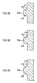
- a vertical section of the cam follower 22 has a substantially trapezoidal shape as illustrated in FIGs. 6A to 6C .
- the top surface of the cam follower 22 is provided with a substantially part-spherical protrusion 22g.
- the protrusion 22g can contact a bottom surface 12m of the cam groove 12 at least when the cam follower 22 moves inside the cam groove 12. This makes it possible to reduce a contact area between the protrusion 22g and the bottom surface 12m. Consequently, the sliding resistance during the movement of the cam follower 22 can be reduced, thereby achieving smooth cam driving.
- FIG. 6A illustrates a cross-section taken at a portion H1 in FIG. 5 .
- FIG. 6B illustrates a cross-section taken at a portion H2 in FIG. 5 .
- FIG. 6C illustrates a cross-section taken at a portion H3 in FIG. 5 .
- the inclined surface 22c includes a first lateral surface 22d (see FIG. 6C ), a second lateral surface 22e (see FIG. 6B ) and a third lateral surface 22f (see FIG. 6A ) that have different inclination angles from each other.
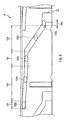
- FIG. 7 is a developmental view of the fixed frame 10, showing an inner structure of the fixed frame 10.
- Each of the cam grooves 12 includes first to sixth regions.
- the first region 12a corresponds to a moving range of the cam follower 22 when the drive frame 20 shifts from the collapsed state to the image capturing standby state.
- the second region 12b corresponds to a moving range of the cam follower 22 in the image capturing standby state.
- the third region 12c corresponds to a moving range of the cam follower 22 when an optical zooming operation is carried out.
- the fourth region 12d corresponds to a moving range of the cam follower 22 when the zoom lens in the optical zooming operation is at a telephoto end.
- the fifth region 12e corresponds to a moving range of the cam follower 22 in the collapsed state.
- the sixth region 12f is a region for inserting the cam follower 22 in the cam groove 12. Further, in each of the regions, the cam groove 12 is set to have an optimal inclination angle with respect to the circumfer
- FIG. 8A illustrates a cross-section taken at a portion M1 in FIG. 7 .
- FIG. 8B illustrates a cross-section taken at a portion M2 in FIG. 7 .
- FIG. 8C illustrates a cross-section taken at a portion M3 in FIG. 7 .
- the cam groove 12 includes a first lateral surface 12g (see FIG. 8A ), a second lateral surface 12h (see FIG. 8B ) and a third lateral surface 12k (see FIG. 8C ) that have different inclination angles from each other.
- ⁇ 4 indicates the inclination angle of the first lateral surface 12g
- ⁇ 5 indicates the inclination angle of the second lateral surface 12h
- ⁇ 6 indicates the inclination angle of the third lateral surface 12k
- the cam groove 12 in the first region 12a is wider than that in the second region 12b and the third region 12c. Also, an inclination angle ⁇ 11 of the cam groove 12 in the first region 12a is larger than the inclination angles thereof in the other regions.
- the inclination angle of the lateral surface 12g of the cam groove 12 in the first region 12a forms a large angle with respect to a depth direction of the cam groove 12. This angle is about 20°, for example. In other words, the angle ⁇ 4 between the lateral surface 12g and the bottom surface 12m is about 110°.
- the lateral surface 12 g of the cam groove 12 contacts the first lateral surface 22d of the cam follower 22 (see FIGs. 5 and 6 ).
- the inclination angle of the first lateral surface 22d is substantially the same as that of the lateral surface 12g. Therefore, the cam follower 22 can move inside the first region 12a without looseness.
- the cam groove 12 is formed substantially in parallel with the circumferential direction of the fixed frame 10. Accordingly, when the cam follower 22 moves inside the second region 12b and the fourth region 12d, the drive frame 20 does not move in the optical axis direction.
- the third region 12c is formed by the cam grooves 12 having an inclination angle ⁇ 12 with respect to the circumferential direction of the fixed frame 10 ( ⁇ 12 ⁇ ⁇ 11).
- the cam follower 22 moves inside the third region 12c
- the drive frame 20 slightly moves in the optical axis direction.
- the imaging apparatus 1 can change an optical zooming factor.
- the inclination angle of the lateral surface 12h of the cam groove 12 in the second region 12b forms a small angle with respect to the depth direction of the cam groove 12.
- the inclination angle of the lateral surface 12h is about 5°, for example.
- the angle ⁇ 5 between the lateral surface 12h and the bottom surface 12m is about 95°.
- the inclination angle of the lateral surface of the cam groove 12 in the fourth region 12d is equivalent to the inclination angle ⁇ 5 shown in FIG. 8B .
- the inclination angle of the lateral surface 12k of the cam groove 12 in the third region 12c forms a small angle with respect to the depth direction of the cam groove 12.
- the inclination angle of the lateral surface 12k is about 5°, for example.
- the angle ⁇ 6 between the lateral surface 12k and the bottom surface 12m is about 95°. It should be noted that the angle ⁇ 6 may be made slightly smaller than the angle ⁇ 5.
- the cam follower 22 moves inside the third region 12c, the lateral surface 12k constantly contacts the second lateral surface 22e of the cam follower 22. Also, when the cam follower 22 moves inside the second region 12b and the fourth region 12d, the lateral surface 12h constantly contacts the third lateral surface 22f of the cam follower 22. Consequently, the cam follower 22 can move inside the cam groove 12 in the second region 12b, the third region 12c and the fourth region 12d without looseness.
- the groove width of the cam groove 12 and the inclination angle of the lateral surface thereof in the fifth region 12e are equivalent to those in the second region 12b.
- FIG. 9 is a drawing for describing the moving operation of the cam follower 22, which shows part of the inner surface of the fixed frame 10.
- numerals 122a to 122e indicate positions of the cam follower 22.
- the cam follower 22 is located in the fifth region 12e as indicated by the position 122a. At this time, the third lateral surface 22f (see FIG. 6A ) of the cam follower 22 contacts the lateral surface of the cam groove 12, thereby suppressing the generation of looseness.
- the control means controls the motor (not shown) to start driving.
- a driving force of the motor is transmitted via the gear 11 (see FIG. 2 ) and the rack 21 (see FIG. 2 ) to the drive frame 20.
- the drive frame 20 rotates in the direction indicated by the arrow E.
- the cam follower 22 moves from the position 122a into the first region 12a. Since the cam groove 12 in the first region 12a is formed so as to be inclined at a large angle with respect to the circumferential direction of the fixed frame 10, the drive frame 20 moves in the direction indicated by the arrow A (see FIG. 2 ) while the cam follower 22 is moving inside the first region 12a. Also, when the cam follower 22 is located in the first region 12a, the first lateral surface 22d (see FIG. 6C ) contacts the first lateral surface 12g (see FIG. 8A ) of the cam groove 12, thereby suppressing the generation of looseness.
- the control means stops the driving of the motor so as to stop the rotational operation of the drive frame 20.
- the zoom lens is at a wide angle end.
- the cam follower 22 is located in the second region 12b, the third lateral surface 22f (see FIG. 6A ) contacts the second lateral surface 12h (see FIG. 8B ) of the cam groove 12, thereby suppressing the generation of looseness.
- the control means controls the motor to perform driving again.
- the drive frame 20 further is driven rotationally in the direction indicated by the arrow E, and the cam follower 22 moves from the position 122c into the third region 12c.
- the cam follower 22 is located in the third region 12c (for example, at the position 122d)
- the second lateral surface 22e contacts the third lateral surface 12k (see FIG. 8C ) of the cam groove 12, thereby suppressing the generation of looseness.
- the cam follower 22 When the zoom lens is moved to the telephoto end, the cam follower 22 is located in the fourth region 12d (for example, at the position 122e). At this time, the third lateral surface 22f (see FIG. 6A ) of the cam follower 22 contacts the lateral surface (equivalent to the second lateral surface 12h shown in FIG. 8B ) of the cam groove 12, thereby suppressing the generation of looseness.
- the lateral surface of the cam follower 22 constantly contacts the lateral surface of the cam groove 12 in each of the fourth region 12d, the third region 12c and the second region 12b, so that the cam follower 22 moves inside the cam groove 12 while suppressing the generation of looseness.
- the control means controls the motor to perform driving.
- the motor performs driving in a reversed direction of rotation, thus driving the drive frame 20 rotationally in the direction indicated by the arrow F (see FIG. 2 ).
- the cam follower 22 moves inside the cam groove 12 toward the fifth region 12e. Since the lateral surface of the cam follower 22 and the lateral surface of the cam groove 12 contact each other constantly during the movement of the cam follower 22 toward the fifth region 12e, the cam follower 22 moves inside the cam groove 12 while suppressing the generation of looseness.
- the cam follower 22 arrives in the fifth region 12e, the movable members such as the drive frame 20, etc. reach the collapsed state shown in FIG. 1 .
- the drive frame 20 and various lenses accompanying the drive frame 20 can be driven with high accuracy. Also, it is possible to suppress the generation of noise resulting from the looseness.
- the inclination angle of the lateral surface of the cam groove 12 in the second region 12b, the third region 12c and the fourth region 12d and the inclination angles of the second lateral surface 22e and the third lateral surface 22f of the cam follower 22 are set to be small. Consequently, even when a large external force due to impact from dropping or the like is applied when the cam follower 22 is located in the regions in which the optical zooming can be changed (the second region 12b, the third region 12c and the fourth region 12d), the cam follower 22 does not demate from the cam groove 12 easily, resulting in an improved impact resistance.
- the cam follower 22 is located in the second region 12b, the third region 12c and the fourth region 12d, a user actually is using the digital camera. Thus, it is of significant importance to improve the impact resistance.
- the inclination angle of the lateral surface 12g of the cam groove 12 in the first region 12a forms a large angle with respect to the depth direction of the cam groove 12. Accordingly, it is possible to provide a die for forming the fixed frame 10 with a large draft. This facilitates the extraction of an inner die for forming the fixed frame 10 from a casting. Also, since it can be made easier to extract the inner die from the casting, the number of split of the inner die can be reduced. Therefore, the production is easy. In the case of a casting whose inner lateral surface is provided with the cam grooves 12, the inner die has to be split into plural parts and extracted inwardly after casting. In this case, reducing the number of splits of the inner die leads to a reduced cost for the die, thus making it easier to produce the casting.
- the number of the cam grooves 12 and the number of the cam followers 22 are not limited to those in the present embodiment. Also, the shape, angle, width, etc. of the cam grooves 12 are not limited to those in the present embodiment. Further, although the cam followers 22 have a substantially elliptical shape in the present embodiment, they also may have other shapes as long as at least two outer diameters are present.
- the present embodiment is directed to the configuration of the imaging apparatus 1 shown in FIG. 2 , there is no particular limitation to this configuration.
- the present invention can be applied to a movable body driving mechanism that is capable of moving by cam driving. More specifically, the present invention is applicable to a lens barrel or the like mounted in a digital still camera, a video camera, a mobile telephone terminal with a camera function, or the like.
- the present invention is directed to a movable body driving mechanism including a first frame and a second frame that is capable of moving relative to the first frame.
- the movable body driving mechanism includes a cam groove that is formed in the first frame, and a cam follower that is formed in the second frame and inserted movably in the cam groove.
- the cam groove includes a plurality of regions having different widths.
- the cam follower is formed to have a shape with a plurality of outer diameters, and different parts of the cam follower contact an inner lateral surface of the cam groove in each of the plurality of regions.
- the lateral surface of the cam follower can be made to contact the lateral surface of the cam groove constantly, thus achieving the cam driving without looseness. Also, since the biasing means or the like is not needed, it is possible both to simplify the configuration and to reduce the number of manufacturing steps.
- the fixed frame 10 in the present embodiment is an example of the first frame.
- the drive frame 20 is an example of the second frame.
- the cam follower can have a protruding shape whose outer diameter decreases from a side of the second frame toward a top portion.
- a lateral surface in a vertical section of the cam follower can have different inclination angles depending on a sectioned position.
Landscapes
- Physics & Mathematics (AREA)
- General Physics & Mathematics (AREA)
- Optics & Photonics (AREA)
- Engineering & Computer Science (AREA)
- General Engineering & Computer Science (AREA)
- Lens Barrels (AREA)
- Transmission Devices (AREA)
Priority Applications (1)
| Application Number | Priority Date | Filing Date | Title |
|---|---|---|---|
| EP12156019.7A EP2458418B1 (en) | 2007-02-08 | 2008-02-07 | Movable body driving mechanism |
Applications Claiming Priority (1)
| Application Number | Priority Date | Filing Date | Title |
|---|---|---|---|
| JP2007028935 | 2007-02-08 |
Related Child Applications (2)
| Application Number | Title | Priority Date | Filing Date |
|---|---|---|---|
| EP12156019.7A Division EP2458418B1 (en) | 2007-02-08 | 2008-02-07 | Movable body driving mechanism |
| EP12156019.7 Division-Into | 2012-02-17 |
Publications (3)
| Publication Number | Publication Date |
|---|---|
| EP2053437A2 EP2053437A2 (en) | 2009-04-29 |
| EP2053437A3 EP2053437A3 (en) | 2009-05-06 |
| EP2053437B1 true EP2053437B1 (en) | 2012-04-25 |
Family
ID=39684711
Family Applications (2)
| Application Number | Title | Priority Date | Filing Date |
|---|---|---|---|
| EP08151175A Active EP2053437B1 (en) | 2007-02-08 | 2008-02-07 | Movable body driving mechanism |
| EP12156019.7A Not-in-force EP2458418B1 (en) | 2007-02-08 | 2008-02-07 | Movable body driving mechanism |
Family Applications After (1)
| Application Number | Title | Priority Date | Filing Date |
|---|---|---|---|
| EP12156019.7A Not-in-force EP2458418B1 (en) | 2007-02-08 | 2008-02-07 | Movable body driving mechanism |
Country Status (5)
| Country | Link |
|---|---|
| US (1) | US8023200B2 (enExample) |
| EP (2) | EP2053437B1 (enExample) |
| JP (4) | JP4988620B2 (enExample) |
| CN (2) | CN101241219B (enExample) |
| AT (1) | ATE555406T1 (enExample) |
Families Citing this family (18)
| Publication number | Priority date | Publication date | Assignee | Title |
|---|---|---|---|---|
| JP5020026B2 (ja) * | 2007-10-19 | 2012-09-05 | パナソニック株式会社 | レンズ鏡筒およびカメラ |
| US8547647B2 (en) * | 2008-01-25 | 2013-10-01 | Panasonic Corporation | Lens barrel |
| WO2010058722A1 (ja) * | 2008-11-21 | 2010-05-27 | コニカミノルタオプト株式会社 | レンズユニット |
| JP5073716B2 (ja) * | 2009-07-03 | 2012-11-14 | Hoya株式会社 | レンズ鏡筒の回転環組付構造 |
| JP5914819B2 (ja) | 2009-07-27 | 2016-05-11 | パナソニックIpマネジメント株式会社 | レンズ鏡筒および撮像装置 |
| JP5671684B2 (ja) * | 2009-08-31 | 2015-02-18 | パナソニックIpマネジメント株式会社 | レンズ鏡筒、撮像装置および携帯端末装置 |
| JP5493851B2 (ja) * | 2009-12-30 | 2014-05-14 | ソニー株式会社 | レンズ鏡筒及び撮像装置 |
| JP5231601B2 (ja) * | 2010-06-14 | 2013-07-10 | パナソニック株式会社 | レンズ鏡筒 |
| CN103135193A (zh) * | 2011-11-24 | 2013-06-05 | 华晶科技股份有限公司 | 变焦机构及其摄像装置 |
| CN103163619B (zh) * | 2011-12-15 | 2015-04-01 | 华晶科技股份有限公司 | 镜头驱动模块及其摄像装置 |
| JP6191119B2 (ja) * | 2012-10-23 | 2017-09-06 | 株式会社ニコン | レンズ鏡筒および撮像装置 |
| JP5966850B2 (ja) * | 2012-10-23 | 2016-08-10 | 株式会社ニコン | レンズ鏡筒および撮像装置 |
| CN104076479B (zh) * | 2013-03-28 | 2017-07-14 | 浙江大华技术股份有限公司 | 镜筒滑块、聚焦镜头、图像采集设备、控制器及控制方法 |
| US9475385B1 (en) | 2015-08-18 | 2016-10-25 | Borgwarner Inc. | Electronic shift on the fly part-time electro mechanical transfer case |
| US9463691B1 (en) | 2016-01-08 | 2016-10-11 | Borgwarner Inc. | Electronic shift on the fly part-time electro mechanical transfer case |
| JP2017203853A (ja) * | 2016-05-10 | 2017-11-16 | キヤノン株式会社 | レンズ鏡筒及びこれを用いた光学機器 |
| JP6485505B2 (ja) * | 2017-08-10 | 2019-03-20 | 株式会社ニコン | レンズ鏡筒および撮像装置 |
| JP2019079079A (ja) * | 2019-02-20 | 2019-05-23 | 株式会社ニコン | レンズ鏡筒および撮像装置 |
Family Cites Families (20)
| Publication number | Priority date | Publication date | Assignee | Title |
|---|---|---|---|---|
| JPS6092216U (ja) * | 1983-11-29 | 1985-06-24 | コニカ株式会社 | レンズ鏡筒 |
| JPH0529013A (ja) | 1991-07-19 | 1993-02-05 | Toshiba Corp | 燃料電池発電システム |
| JPH0529013U (ja) | 1991-09-26 | 1993-04-16 | 株式会社タムロン | レンズ鏡筒 |
| JPH0651178A (ja) * | 1992-07-31 | 1994-02-25 | Olympus Optical Co Ltd | 鏡 筒 |
| US5805353A (en) * | 1992-12-25 | 1998-09-08 | Canon Kabushiki Kaisha | Optical system moving device |
| JPH06250063A (ja) * | 1993-02-24 | 1994-09-09 | Canon Inc | レンズ鏡筒および円筒部材の嵌合機構 |
| JPH07191252A (ja) * | 1993-12-27 | 1995-07-28 | Canon Inc | カメラ |
| JPH09189844A (ja) * | 1996-01-10 | 1997-07-22 | Fuji Photo Optical Co Ltd | レンズ鏡筒 |
| JP4051781B2 (ja) * | 1998-11-11 | 2008-02-27 | 株式会社ニコン | 可変焦点距離レンズ鏡筒 |
| US6195212B1 (en) * | 1998-11-11 | 2001-02-27 | Nikon Corporation | Variable focal length lens barrel |
| JP3610254B2 (ja) * | 1999-02-26 | 2005-01-12 | キヤノン株式会社 | レンズ鏡筒およびカメラ |
| JP4070350B2 (ja) * | 1999-04-06 | 2008-04-02 | 富士フイルム株式会社 | 光学機器 |
| JP2001235669A (ja) * | 2000-02-23 | 2001-08-31 | Fuji Photo Optical Co Ltd | レンズ装置 |
| US6487025B2 (en) * | 2000-03-31 | 2002-11-26 | Olympus Optical Co., Ltd. | Lens barrel having a plurality of lens frames which are relatively movable in forward and backward directions |
| JP4580516B2 (ja) * | 2000-07-12 | 2010-11-17 | オリンパス株式会社 | 鏡枠装置 |
| JP4695298B2 (ja) * | 2001-06-28 | 2011-06-08 | オリンパス株式会社 | レンズ鏡筒 |
| JP2003084186A (ja) * | 2001-09-10 | 2003-03-19 | Fuji Photo Optical Co Ltd | レンズ鏡胴 |
| JP4638665B2 (ja) * | 2002-10-11 | 2011-02-23 | Hoya株式会社 | レンズ鏡筒 |
| JP2004361519A (ja) * | 2003-06-02 | 2004-12-24 | Nidec Copal Corp | レンズ鏡胴の駆動装置 |
| JP4724363B2 (ja) * | 2003-11-05 | 2011-07-13 | キヤノン株式会社 | レンズ鏡筒及び撮像装置 |
-
2008
- 2008-02-05 CN CN2008100048999A patent/CN101241219B/zh active Active
- 2008-02-05 CN CN201210142547.6A patent/CN102654633B/zh not_active Expired - Fee Related
- 2008-02-06 JP JP2008026829A patent/JP4988620B2/ja active Active
- 2008-02-07 EP EP08151175A patent/EP2053437B1/en active Active
- 2008-02-07 EP EP12156019.7A patent/EP2458418B1/en not_active Not-in-force
- 2008-02-07 US US12/027,610 patent/US8023200B2/en active Active
- 2008-02-07 AT AT08151175T patent/ATE555406T1/de active
-
2011
- 2011-12-12 JP JP2011271590A patent/JP5465710B2/ja not_active Expired - Fee Related
- 2011-12-12 JP JP2011271592A patent/JP5444317B2/ja not_active Expired - Fee Related
- 2011-12-12 JP JP2011271591A patent/JP5444316B2/ja active Active
Also Published As
| Publication number | Publication date |
|---|---|
| JP2012053496A (ja) | 2012-03-15 |
| EP2053437A3 (en) | 2009-05-06 |
| EP2458418B1 (en) | 2014-07-02 |
| CN102654633B (zh) | 2014-11-26 |
| JP4988620B2 (ja) | 2012-08-01 |
| CN102654633A (zh) | 2012-09-05 |
| US20080190241A1 (en) | 2008-08-14 |
| JP5444316B2 (ja) | 2014-03-19 |
| CN101241219A (zh) | 2008-08-13 |
| CN101241219B (zh) | 2012-09-05 |
| ATE555406T1 (de) | 2012-05-15 |
| EP2458418A2 (en) | 2012-05-30 |
| JP2012053494A (ja) | 2012-03-15 |
| JP2008217000A (ja) | 2008-09-18 |
| EP2053437A2 (en) | 2009-04-29 |
| EP2458418A3 (en) | 2012-09-12 |
| JP2012053495A (ja) | 2012-03-15 |
| JP5444317B2 (ja) | 2014-03-19 |
| JP5465710B2 (ja) | 2014-04-09 |
| US8023200B2 (en) | 2011-09-20 |
Similar Documents
| Publication | Publication Date | Title |
|---|---|---|
| EP2053437B1 (en) | Movable body driving mechanism | |
| US7369333B2 (en) | Lens unit and image capturing apparatus | |
| US8780456B2 (en) | Lens barrel | |
| JP2008242068A (ja) | レンズ鏡胴、撮像装置および情報端末装置 | |
| CN105116513A (zh) | 透镜镜筒和凸轮机构 | |
| JP4461244B2 (ja) | レンズ移動装置 | |
| JP5566163B2 (ja) | レンズ鏡筒及び撮像装置 | |
| JP5566164B2 (ja) | レンズ鏡筒及び撮像装置 | |
| US9182568B2 (en) | Lens barrel | |
| EP1830208A1 (en) | Zoom lens device | |
| JP4572914B2 (ja) | レンズの移動機構 | |
| JP6271996B2 (ja) | レンズ鏡筒及び撮影装置 | |
| JP2008242396A (ja) | レンズ鏡筒及びカメラ | |
| JP5963589B2 (ja) | レンズ鏡筒、及び撮像装置 | |
| KR200416180Y1 (ko) | 줌렌즈 조립체 | |
| JP2007064992A (ja) | レンズ鏡胴ユニット | |
| KR20070089291A (ko) | 줌렌즈 조립체 | |
| JP2006038972A (ja) | 光学装置 | |
| JP2001356255A (ja) | レンズ鏡筒 |
Legal Events
| Date | Code | Title | Description |
|---|---|---|---|
| PUAI | Public reference made under article 153(3) epc to a published international application that has entered the european phase |
Free format text: ORIGINAL CODE: 0009012 |
|
| PUAL | Search report despatched |
Free format text: ORIGINAL CODE: 0009013 |
|
| AK | Designated contracting states |
Kind code of ref document: A2 Designated state(s): AT BE BG CH CY CZ DE DK EE ES FI FR GB GR HR HU IE IS IT LI LT LU LV MC MT NL NO PL PT RO SE SI SK TR |
|
| AX | Request for extension of the european patent |
Extension state: AL BA MK RS |
|
| AK | Designated contracting states |
Kind code of ref document: A3 Designated state(s): AT BE BG CH CY CZ DE DK EE ES FI FR GB GR HR HU IE IS IT LI LT LU LV MC MT NL NO PL PT RO SE SI SK TR |
|
| AX | Request for extension of the european patent |
Extension state: AL BA MK RS |
|
| 17P | Request for examination filed |
Effective date: 20091106 |
|
| AKX | Designation fees paid |
Designated state(s): AT BE BG CH CY CZ DE DK EE ES FI FR GB GR HR HU IE IS IT LI LT LU LV MC MT NL NO PL PT RO SE SI SK TR |
|
| 17Q | First examination report despatched |
Effective date: 20100331 |
|
| GRAP | Despatch of communication of intention to grant a patent |
Free format text: ORIGINAL CODE: EPIDOSNIGR1 |
|
| RIN1 | Information on inventor provided before grant (corrected) |
Inventor name: FUJINAKA, HIROYASU,C/O PANASONIC CORPORATION Inventor name: KUWAHARA, TAKUMI,C/O PANASONIC CORPORATION |
|
| GRAS | Grant fee paid |
Free format text: ORIGINAL CODE: EPIDOSNIGR3 |
|
| GRAA | (expected) grant |
Free format text: ORIGINAL CODE: 0009210 |
|
| AK | Designated contracting states |
Kind code of ref document: B1 Designated state(s): AT BE BG CH CY CZ DE DK EE ES FI FR GB GR HR HU IE IS IT LI LT LU LV MC MT NL NO PL PT RO SE SI SK TR |
|
| REG | Reference to a national code |
Ref country code: GB Ref legal event code: FG4D |
|
| REG | Reference to a national code |
Ref country code: CH Ref legal event code: EP |
|
| REG | Reference to a national code |
Ref country code: AT Ref legal event code: REF Ref document number: 555406 Country of ref document: AT Kind code of ref document: T Effective date: 20120515 |
|
| REG | Reference to a national code |
Ref country code: IE Ref legal event code: FG4D |
|
| REG | Reference to a national code |
Ref country code: DE Ref legal event code: R096 Ref document number: 602008015126 Country of ref document: DE Effective date: 20120621 |
|
| REG | Reference to a national code |
Ref country code: NL Ref legal event code: VDEP Effective date: 20120425 |
|
| REG | Reference to a national code |
Ref country code: AT Ref legal event code: MK05 Ref document number: 555406 Country of ref document: AT Kind code of ref document: T Effective date: 20120425 |
|
| LTIE | Lt: invalidation of european patent or patent extension |
Effective date: 20120425 |
|
| PG25 | Lapsed in a contracting state [announced via postgrant information from national office to epo] |
Ref country code: SE Free format text: LAPSE BECAUSE OF FAILURE TO SUBMIT A TRANSLATION OF THE DESCRIPTION OR TO PAY THE FEE WITHIN THE PRESCRIBED TIME-LIMIT Effective date: 20120425 Ref country code: FI Free format text: LAPSE BECAUSE OF FAILURE TO SUBMIT A TRANSLATION OF THE DESCRIPTION OR TO PAY THE FEE WITHIN THE PRESCRIBED TIME-LIMIT Effective date: 20120425 Ref country code: CY Free format text: LAPSE BECAUSE OF FAILURE TO SUBMIT A TRANSLATION OF THE DESCRIPTION OR TO PAY THE FEE WITHIN THE PRESCRIBED TIME-LIMIT Effective date: 20120425 Ref country code: LT Free format text: LAPSE BECAUSE OF FAILURE TO SUBMIT A TRANSLATION OF THE DESCRIPTION OR TO PAY THE FEE WITHIN THE PRESCRIBED TIME-LIMIT Effective date: 20120425 Ref country code: IS Free format text: LAPSE BECAUSE OF FAILURE TO SUBMIT A TRANSLATION OF THE DESCRIPTION OR TO PAY THE FEE WITHIN THE PRESCRIBED TIME-LIMIT Effective date: 20120825 Ref country code: PL Free format text: LAPSE BECAUSE OF FAILURE TO SUBMIT A TRANSLATION OF THE DESCRIPTION OR TO PAY THE FEE WITHIN THE PRESCRIBED TIME-LIMIT Effective date: 20120425 Ref country code: NO Free format text: LAPSE BECAUSE OF FAILURE TO SUBMIT A TRANSLATION OF THE DESCRIPTION OR TO PAY THE FEE WITHIN THE PRESCRIBED TIME-LIMIT Effective date: 20120725 |
|
| PG25 | Lapsed in a contracting state [announced via postgrant information from national office to epo] |
Ref country code: SI Free format text: LAPSE BECAUSE OF FAILURE TO SUBMIT A TRANSLATION OF THE DESCRIPTION OR TO PAY THE FEE WITHIN THE PRESCRIBED TIME-LIMIT Effective date: 20120425 Ref country code: LV Free format text: LAPSE BECAUSE OF FAILURE TO SUBMIT A TRANSLATION OF THE DESCRIPTION OR TO PAY THE FEE WITHIN THE PRESCRIBED TIME-LIMIT Effective date: 20120425 Ref country code: GR Free format text: LAPSE BECAUSE OF FAILURE TO SUBMIT A TRANSLATION OF THE DESCRIPTION OR TO PAY THE FEE WITHIN THE PRESCRIBED TIME-LIMIT Effective date: 20120726 Ref country code: HR Free format text: LAPSE BECAUSE OF FAILURE TO SUBMIT A TRANSLATION OF THE DESCRIPTION OR TO PAY THE FEE WITHIN THE PRESCRIBED TIME-LIMIT Effective date: 20120425 Ref country code: PT Free format text: LAPSE BECAUSE OF FAILURE TO SUBMIT A TRANSLATION OF THE DESCRIPTION OR TO PAY THE FEE WITHIN THE PRESCRIBED TIME-LIMIT Effective date: 20120827 |
|
| PG25 | Lapsed in a contracting state [announced via postgrant information from national office to epo] |
Ref country code: BE Free format text: LAPSE BECAUSE OF FAILURE TO SUBMIT A TRANSLATION OF THE DESCRIPTION OR TO PAY THE FEE WITHIN THE PRESCRIBED TIME-LIMIT Effective date: 20120425 |
|
| PG25 | Lapsed in a contracting state [announced via postgrant information from national office to epo] |
Ref country code: SK Free format text: LAPSE BECAUSE OF FAILURE TO SUBMIT A TRANSLATION OF THE DESCRIPTION OR TO PAY THE FEE WITHIN THE PRESCRIBED TIME-LIMIT Effective date: 20120425 Ref country code: AT Free format text: LAPSE BECAUSE OF FAILURE TO SUBMIT A TRANSLATION OF THE DESCRIPTION OR TO PAY THE FEE WITHIN THE PRESCRIBED TIME-LIMIT Effective date: 20120425 Ref country code: EE Free format text: LAPSE BECAUSE OF FAILURE TO SUBMIT A TRANSLATION OF THE DESCRIPTION OR TO PAY THE FEE WITHIN THE PRESCRIBED TIME-LIMIT Effective date: 20120425 Ref country code: DK Free format text: LAPSE BECAUSE OF FAILURE TO SUBMIT A TRANSLATION OF THE DESCRIPTION OR TO PAY THE FEE WITHIN THE PRESCRIBED TIME-LIMIT Effective date: 20120425 Ref country code: RO Free format text: LAPSE BECAUSE OF FAILURE TO SUBMIT A TRANSLATION OF THE DESCRIPTION OR TO PAY THE FEE WITHIN THE PRESCRIBED TIME-LIMIT Effective date: 20120425 Ref country code: NL Free format text: LAPSE BECAUSE OF FAILURE TO SUBMIT A TRANSLATION OF THE DESCRIPTION OR TO PAY THE FEE WITHIN THE PRESCRIBED TIME-LIMIT Effective date: 20120425 Ref country code: CZ Free format text: LAPSE BECAUSE OF FAILURE TO SUBMIT A TRANSLATION OF THE DESCRIPTION OR TO PAY THE FEE WITHIN THE PRESCRIBED TIME-LIMIT Effective date: 20120425 |
|
| PG25 | Lapsed in a contracting state [announced via postgrant information from national office to epo] |
Ref country code: IT Free format text: LAPSE BECAUSE OF FAILURE TO SUBMIT A TRANSLATION OF THE DESCRIPTION OR TO PAY THE FEE WITHIN THE PRESCRIBED TIME-LIMIT Effective date: 20120425 |
|
| PLBE | No opposition filed within time limit |
Free format text: ORIGINAL CODE: 0009261 |
|
| STAA | Information on the status of an ep patent application or granted ep patent |
Free format text: STATUS: NO OPPOSITION FILED WITHIN TIME LIMIT |
|
| 26N | No opposition filed |
Effective date: 20130128 |
|
| PG25 | Lapsed in a contracting state [announced via postgrant information from national office to epo] |
Ref country code: ES Free format text: LAPSE BECAUSE OF FAILURE TO SUBMIT A TRANSLATION OF THE DESCRIPTION OR TO PAY THE FEE WITHIN THE PRESCRIBED TIME-LIMIT Effective date: 20120805 |
|
| REG | Reference to a national code |
Ref country code: DE Ref legal event code: R097 Ref document number: 602008015126 Country of ref document: DE Effective date: 20130128 |
|
| PG25 | Lapsed in a contracting state [announced via postgrant information from national office to epo] |
Ref country code: BG Free format text: LAPSE BECAUSE OF FAILURE TO SUBMIT A TRANSLATION OF THE DESCRIPTION OR TO PAY THE FEE WITHIN THE PRESCRIBED TIME-LIMIT Effective date: 20120725 |
|
| PG25 | Lapsed in a contracting state [announced via postgrant information from national office to epo] |
Ref country code: MC Free format text: LAPSE BECAUSE OF NON-PAYMENT OF DUE FEES Effective date: 20130228 |
|
| REG | Reference to a national code |
Ref country code: CH Ref legal event code: PL |
|
| PG25 | Lapsed in a contracting state [announced via postgrant information from national office to epo] |
Ref country code: CH Free format text: LAPSE BECAUSE OF NON-PAYMENT OF DUE FEES Effective date: 20130228 Ref country code: LI Free format text: LAPSE BECAUSE OF NON-PAYMENT OF DUE FEES Effective date: 20130228 |
|
| REG | Reference to a national code |
Ref country code: IE Ref legal event code: MM4A |
|
| PG25 | Lapsed in a contracting state [announced via postgrant information from national office to epo] |
Ref country code: IE Free format text: LAPSE BECAUSE OF NON-PAYMENT OF DUE FEES Effective date: 20130207 |
|
| PG25 | Lapsed in a contracting state [announced via postgrant information from national office to epo] |
Ref country code: MT Free format text: LAPSE BECAUSE OF FAILURE TO SUBMIT A TRANSLATION OF THE DESCRIPTION OR TO PAY THE FEE WITHIN THE PRESCRIBED TIME-LIMIT Effective date: 20120425 |
|
| PG25 | Lapsed in a contracting state [announced via postgrant information from national office to epo] |
Ref country code: TR Free format text: LAPSE BECAUSE OF FAILURE TO SUBMIT A TRANSLATION OF THE DESCRIPTION OR TO PAY THE FEE WITHIN THE PRESCRIBED TIME-LIMIT Effective date: 20120425 |
|
| PG25 | Lapsed in a contracting state [announced via postgrant information from national office to epo] |
Ref country code: HU Free format text: LAPSE BECAUSE OF FAILURE TO SUBMIT A TRANSLATION OF THE DESCRIPTION OR TO PAY THE FEE WITHIN THE PRESCRIBED TIME-LIMIT; INVALID AB INITIO Effective date: 20080207 Ref country code: LU Free format text: LAPSE BECAUSE OF NON-PAYMENT OF DUE FEES Effective date: 20130207 |
|
| REG | Reference to a national code |
Ref country code: FR Ref legal event code: PLFP Year of fee payment: 9 |
|
| REG | Reference to a national code |
Ref country code: FR Ref legal event code: PLFP Year of fee payment: 10 |
|
| REG | Reference to a national code |
Ref country code: FR Ref legal event code: PLFP Year of fee payment: 11 |
|
| PGFP | Annual fee paid to national office [announced via postgrant information from national office to epo] |
Ref country code: DE Payment date: 20250218 Year of fee payment: 18 |
|
| PGFP | Annual fee paid to national office [announced via postgrant information from national office to epo] |
Ref country code: FR Payment date: 20250221 Year of fee payment: 18 |
|
| PGFP | Annual fee paid to national office [announced via postgrant information from national office to epo] |
Ref country code: GB Payment date: 20250219 Year of fee payment: 18 |