EP2048115A2 - Zeolithzusammensetzung - Google Patents
Zeolithzusammensetzung Download PDFInfo
- Publication number
- EP2048115A2 EP2048115A2 EP09075049A EP09075049A EP2048115A2 EP 2048115 A2 EP2048115 A2 EP 2048115A2 EP 09075049 A EP09075049 A EP 09075049A EP 09075049 A EP09075049 A EP 09075049A EP 2048115 A2 EP2048115 A2 EP 2048115A2
- Authority
- EP
- European Patent Office
- Prior art keywords
- zeolite
- composition
- trap
- soot
- exhaust
- Prior art date
- Legal status (The legal status is an assumption and is not a legal conclusion. Google has not performed a legal analysis and makes no representation as to the accuracy of the status listed.)
- Withdrawn
Links
Images


Classifications
-
- F—MECHANICAL ENGINEERING; LIGHTING; HEATING; WEAPONS; BLASTING
- F01—MACHINES OR ENGINES IN GENERAL; ENGINE PLANTS IN GENERAL; STEAM ENGINES
- F01N—GAS-FLOW SILENCERS OR EXHAUST APPARATUS FOR MACHINES OR ENGINES IN GENERAL; GAS-FLOW SILENCERS OR EXHAUST APPARATUS FOR INTERNAL-COMBUSTION ENGINES
- F01N3/00—Exhaust or silencing apparatus having means for purifying, rendering innocuous, or otherwise treating exhaust
- F01N3/08—Exhaust or silencing apparatus having means for purifying, rendering innocuous, or otherwise treating exhaust for rendering innocuous
- F01N3/0807—Exhaust or silencing apparatus having means for purifying, rendering innocuous, or otherwise treating exhaust for rendering innocuous by using absorbents or adsorbents
- F01N3/0828—Exhaust or silencing apparatus having means for purifying, rendering innocuous, or otherwise treating exhaust for rendering innocuous by using absorbents or adsorbents characterised by the absorbed or adsorbed substances
- F01N3/0835—Hydrocarbons
-
- B—PERFORMING OPERATIONS; TRANSPORTING
- B01—PHYSICAL OR CHEMICAL PROCESSES OR APPARATUS IN GENERAL
- B01D—SEPARATION
- B01D53/00—Separation of gases or vapours; Recovering vapours of volatile solvents from gases; Chemical or biological purification of waste gases, e.g. engine exhaust gases, smoke, fumes, flue gases, aerosols
- B01D53/34—Chemical or biological purification of waste gases
- B01D53/92—Chemical or biological purification of waste gases of engine exhaust gases
- B01D53/94—Chemical or biological purification of waste gases of engine exhaust gases by catalytic processes
- B01D53/9404—Removing only nitrogen compounds
- B01D53/9409—Nitrogen oxides
- B01D53/9431—Processes characterised by a specific device
-
- B—PERFORMING OPERATIONS; TRANSPORTING
- B01—PHYSICAL OR CHEMICAL PROCESSES OR APPARATUS IN GENERAL
- B01J—CHEMICAL OR PHYSICAL PROCESSES, e.g. CATALYSIS OR COLLOID CHEMISTRY; THEIR RELEVANT APPARATUS
- B01J29/00—Catalysts comprising molecular sieves
- B01J29/04—Catalysts comprising molecular sieves having base-exchange properties, e.g. crystalline zeolites
- B01J29/06—Crystalline aluminosilicate zeolites; Isomorphous compounds thereof
- B01J29/08—Crystalline aluminosilicate zeolites; Isomorphous compounds thereof of the faujasite type, e.g. type X or Y
- B01J29/16—Crystalline aluminosilicate zeolites; Isomorphous compounds thereof of the faujasite type, e.g. type X or Y containing arsenic, antimony, bismuth, vanadium, niobium, tantalum, polonium, chromium, molybdenum, tungsten, manganese, technetium or rhenium
- B01J29/166—Y-type faujasite
-
- B—PERFORMING OPERATIONS; TRANSPORTING
- B01—PHYSICAL OR CHEMICAL PROCESSES OR APPARATUS IN GENERAL
- B01J—CHEMICAL OR PHYSICAL PROCESSES, e.g. CATALYSIS OR COLLOID CHEMISTRY; THEIR RELEVANT APPARATUS
- B01J29/00—Catalysts comprising molecular sieves
- B01J29/04—Catalysts comprising molecular sieves having base-exchange properties, e.g. crystalline zeolites
- B01J29/06—Crystalline aluminosilicate zeolites; Isomorphous compounds thereof
- B01J29/40—Crystalline aluminosilicate zeolites; Isomorphous compounds thereof of the pentasil type, e.g. types ZSM-5, ZSM-8 or ZSM-11, as exemplified by patent documents US3702886, GB1334243 and US3709979, respectively
- B01J29/42—Crystalline aluminosilicate zeolites; Isomorphous compounds thereof of the pentasil type, e.g. types ZSM-5, ZSM-8 or ZSM-11, as exemplified by patent documents US3702886, GB1334243 and US3709979, respectively containing iron group metals, noble metals or copper
- B01J29/44—Noble metals
-
- B—PERFORMING OPERATIONS; TRANSPORTING
- B01—PHYSICAL OR CHEMICAL PROCESSES OR APPARATUS IN GENERAL
- B01J—CHEMICAL OR PHYSICAL PROCESSES, e.g. CATALYSIS OR COLLOID CHEMISTRY; THEIR RELEVANT APPARATUS
- B01J29/00—Catalysts comprising molecular sieves
- B01J29/04—Catalysts comprising molecular sieves having base-exchange properties, e.g. crystalline zeolites
- B01J29/06—Crystalline aluminosilicate zeolites; Isomorphous compounds thereof
- B01J29/70—Crystalline aluminosilicate zeolites; Isomorphous compounds thereof of types characterised by their specific structure not provided for in groups B01J29/08 - B01J29/65
- B01J29/78—Crystalline aluminosilicate zeolites; Isomorphous compounds thereof of types characterised by their specific structure not provided for in groups B01J29/08 - B01J29/65 containing arsenic, antimony, bismuth, vanadium, niobium, tantalum, polonium, chromium, molybdenum, tungsten, manganese, technetium or rhenium
-
- B—PERFORMING OPERATIONS; TRANSPORTING
- B01—PHYSICAL OR CHEMICAL PROCESSES OR APPARATUS IN GENERAL
- B01J—CHEMICAL OR PHYSICAL PROCESSES, e.g. CATALYSIS OR COLLOID CHEMISTRY; THEIR RELEVANT APPARATUS
- B01J35/00—Catalysts, in general, characterised by their form or physical properties
- B01J35/19—Catalysts containing parts with different compositions
-
- F—MECHANICAL ENGINEERING; LIGHTING; HEATING; WEAPONS; BLASTING
- F01—MACHINES OR ENGINES IN GENERAL; ENGINE PLANTS IN GENERAL; STEAM ENGINES
- F01N—GAS-FLOW SILENCERS OR EXHAUST APPARATUS FOR MACHINES OR ENGINES IN GENERAL; GAS-FLOW SILENCERS OR EXHAUST APPARATUS FOR INTERNAL-COMBUSTION ENGINES
- F01N13/00—Exhaust or silencing apparatus characterised by constructional features
- F01N13/009—Exhaust or silencing apparatus characterised by constructional features having two or more separate purifying devices arranged in series
- F01N13/0097—Exhaust or silencing apparatus characterised by constructional features having two or more separate purifying devices arranged in series the purifying devices are arranged in a single housing
-
- F—MECHANICAL ENGINEERING; LIGHTING; HEATING; WEAPONS; BLASTING
- F01—MACHINES OR ENGINES IN GENERAL; ENGINE PLANTS IN GENERAL; STEAM ENGINES
- F01N—GAS-FLOW SILENCERS OR EXHAUST APPARATUS FOR MACHINES OR ENGINES IN GENERAL; GAS-FLOW SILENCERS OR EXHAUST APPARATUS FOR INTERNAL-COMBUSTION ENGINES
- F01N3/00—Exhaust or silencing apparatus having means for purifying, rendering innocuous, or otherwise treating exhaust
- F01N3/02—Exhaust or silencing apparatus having means for purifying, rendering innocuous, or otherwise treating exhaust for cooling, or for removing solid constituents of, exhaust
- F01N3/021—Exhaust or silencing apparatus having means for purifying, rendering innocuous, or otherwise treating exhaust for cooling, or for removing solid constituents of, exhaust by means of filters
- F01N3/023—Exhaust or silencing apparatus having means for purifying, rendering innocuous, or otherwise treating exhaust for cooling, or for removing solid constituents of, exhaust by means of filters using means for regenerating the filters, e.g. by burning trapped particles
- F01N3/0231—Exhaust or silencing apparatus having means for purifying, rendering innocuous, or otherwise treating exhaust for cooling, or for removing solid constituents of, exhaust by means of filters using means for regenerating the filters, e.g. by burning trapped particles using special exhaust apparatus upstream of the filter for producing nitrogen dioxide, e.g. for continuous filter regeneration systems [CRT]
-
- F—MECHANICAL ENGINEERING; LIGHTING; HEATING; WEAPONS; BLASTING
- F01—MACHINES OR ENGINES IN GENERAL; ENGINE PLANTS IN GENERAL; STEAM ENGINES
- F01N—GAS-FLOW SILENCERS OR EXHAUST APPARATUS FOR MACHINES OR ENGINES IN GENERAL; GAS-FLOW SILENCERS OR EXHAUST APPARATUS FOR INTERNAL-COMBUSTION ENGINES
- F01N3/00—Exhaust or silencing apparatus having means for purifying, rendering innocuous, or otherwise treating exhaust
- F01N3/02—Exhaust or silencing apparatus having means for purifying, rendering innocuous, or otherwise treating exhaust for cooling, or for removing solid constituents of, exhaust
- F01N3/021—Exhaust or silencing apparatus having means for purifying, rendering innocuous, or otherwise treating exhaust for cooling, or for removing solid constituents of, exhaust by means of filters
- F01N3/033—Exhaust or silencing apparatus having means for purifying, rendering innocuous, or otherwise treating exhaust for cooling, or for removing solid constituents of, exhaust by means of filters in combination with other devices
- F01N3/035—Exhaust or silencing apparatus having means for purifying, rendering innocuous, or otherwise treating exhaust for cooling, or for removing solid constituents of, exhaust by means of filters in combination with other devices with catalytic reactors
-
- F—MECHANICAL ENGINEERING; LIGHTING; HEATING; WEAPONS; BLASTING
- F01—MACHINES OR ENGINES IN GENERAL; ENGINE PLANTS IN GENERAL; STEAM ENGINES
- F01N—GAS-FLOW SILENCERS OR EXHAUST APPARATUS FOR MACHINES OR ENGINES IN GENERAL; GAS-FLOW SILENCERS OR EXHAUST APPARATUS FOR INTERNAL-COMBUSTION ENGINES
- F01N3/00—Exhaust or silencing apparatus having means for purifying, rendering innocuous, or otherwise treating exhaust
- F01N3/08—Exhaust or silencing apparatus having means for purifying, rendering innocuous, or otherwise treating exhaust for rendering innocuous
- F01N3/0807—Exhaust or silencing apparatus having means for purifying, rendering innocuous, or otherwise treating exhaust for rendering innocuous by using absorbents or adsorbents
- F01N3/0828—Exhaust or silencing apparatus having means for purifying, rendering innocuous, or otherwise treating exhaust for rendering innocuous by using absorbents or adsorbents characterised by the absorbed or adsorbed substances
- F01N3/0842—Nitrogen oxides
-
- F—MECHANICAL ENGINEERING; LIGHTING; HEATING; WEAPONS; BLASTING
- F01—MACHINES OR ENGINES IN GENERAL; ENGINE PLANTS IN GENERAL; STEAM ENGINES
- F01N—GAS-FLOW SILENCERS OR EXHAUST APPARATUS FOR MACHINES OR ENGINES IN GENERAL; GAS-FLOW SILENCERS OR EXHAUST APPARATUS FOR INTERNAL-COMBUSTION ENGINES
- F01N2330/00—Structure of catalyst support or particle filter
- F01N2330/06—Ceramic, e.g. monoliths
-
- F—MECHANICAL ENGINEERING; LIGHTING; HEATING; WEAPONS; BLASTING
- F01—MACHINES OR ENGINES IN GENERAL; ENGINE PLANTS IN GENERAL; STEAM ENGINES
- F01N—GAS-FLOW SILENCERS OR EXHAUST APPARATUS FOR MACHINES OR ENGINES IN GENERAL; GAS-FLOW SILENCERS OR EXHAUST APPARATUS FOR INTERNAL-COMBUSTION ENGINES
- F01N2330/00—Structure of catalyst support or particle filter
- F01N2330/12—Metallic wire mesh fabric or knitting
-
- F—MECHANICAL ENGINEERING; LIGHTING; HEATING; WEAPONS; BLASTING
- F01—MACHINES OR ENGINES IN GENERAL; ENGINE PLANTS IN GENERAL; STEAM ENGINES
- F01N—GAS-FLOW SILENCERS OR EXHAUST APPARATUS FOR MACHINES OR ENGINES IN GENERAL; GAS-FLOW SILENCERS OR EXHAUST APPARATUS FOR INTERNAL-COMBUSTION ENGINES
- F01N2370/00—Selection of materials for exhaust purification
- F01N2370/22—Selection of materials for exhaust purification used in non-catalytic purification apparatus
- F01N2370/24—Zeolitic material
-
- F—MECHANICAL ENGINEERING; LIGHTING; HEATING; WEAPONS; BLASTING
- F01—MACHINES OR ENGINES IN GENERAL; ENGINE PLANTS IN GENERAL; STEAM ENGINES
- F01N—GAS-FLOW SILENCERS OR EXHAUST APPARATUS FOR MACHINES OR ENGINES IN GENERAL; GAS-FLOW SILENCERS OR EXHAUST APPARATUS FOR INTERNAL-COMBUSTION ENGINES
- F01N2510/00—Surface coverings
- F01N2510/06—Surface coverings for exhaust purification, e.g. catalytic reaction
- F01N2510/065—Surface coverings for exhaust purification, e.g. catalytic reaction for reducing soot ignition temperature
-
- F—MECHANICAL ENGINEERING; LIGHTING; HEATING; WEAPONS; BLASTING
- F01—MACHINES OR ENGINES IN GENERAL; ENGINE PLANTS IN GENERAL; STEAM ENGINES
- F01N—GAS-FLOW SILENCERS OR EXHAUST APPARATUS FOR MACHINES OR ENGINES IN GENERAL; GAS-FLOW SILENCERS OR EXHAUST APPARATUS FOR INTERNAL-COMBUSTION ENGINES
- F01N2570/00—Exhaust treating apparatus eliminating, absorbing or adsorbing specific elements or compounds
- F01N2570/10—Carbon or carbon oxides
-
- F—MECHANICAL ENGINEERING; LIGHTING; HEATING; WEAPONS; BLASTING
- F01—MACHINES OR ENGINES IN GENERAL; ENGINE PLANTS IN GENERAL; STEAM ENGINES
- F01N—GAS-FLOW SILENCERS OR EXHAUST APPARATUS FOR MACHINES OR ENGINES IN GENERAL; GAS-FLOW SILENCERS OR EXHAUST APPARATUS FOR INTERNAL-COMBUSTION ENGINES
- F01N2570/00—Exhaust treating apparatus eliminating, absorbing or adsorbing specific elements or compounds
- F01N2570/12—Hydrocarbons
-
- F—MECHANICAL ENGINEERING; LIGHTING; HEATING; WEAPONS; BLASTING
- F01—MACHINES OR ENGINES IN GENERAL; ENGINE PLANTS IN GENERAL; STEAM ENGINES
- F01N—GAS-FLOW SILENCERS OR EXHAUST APPARATUS FOR MACHINES OR ENGINES IN GENERAL; GAS-FLOW SILENCERS OR EXHAUST APPARATUS FOR INTERNAL-COMBUSTION ENGINES
- F01N2570/00—Exhaust treating apparatus eliminating, absorbing or adsorbing specific elements or compounds
- F01N2570/14—Nitrogen oxides
-
- F—MECHANICAL ENGINEERING; LIGHTING; HEATING; WEAPONS; BLASTING
- F01—MACHINES OR ENGINES IN GENERAL; ENGINE PLANTS IN GENERAL; STEAM ENGINES
- F01N—GAS-FLOW SILENCERS OR EXHAUST APPARATUS FOR MACHINES OR ENGINES IN GENERAL; GAS-FLOW SILENCERS OR EXHAUST APPARATUS FOR INTERNAL-COMBUSTION ENGINES
- F01N3/00—Exhaust or silencing apparatus having means for purifying, rendering innocuous, or otherwise treating exhaust
- F01N3/02—Exhaust or silencing apparatus having means for purifying, rendering innocuous, or otherwise treating exhaust for cooling, or for removing solid constituents of, exhaust
- F01N3/021—Exhaust or silencing apparatus having means for purifying, rendering innocuous, or otherwise treating exhaust for cooling, or for removing solid constituents of, exhaust by means of filters
- F01N3/022—Exhaust or silencing apparatus having means for purifying, rendering innocuous, or otherwise treating exhaust for cooling, or for removing solid constituents of, exhaust by means of filters characterised by specially adapted filtering structure, e.g. honeycomb, mesh or fibrous
- F01N3/0222—Exhaust or silencing apparatus having means for purifying, rendering innocuous, or otherwise treating exhaust for cooling, or for removing solid constituents of, exhaust by means of filters characterised by specially adapted filtering structure, e.g. honeycomb, mesh or fibrous the structure being monolithic, e.g. honeycombs
-
- F—MECHANICAL ENGINEERING; LIGHTING; HEATING; WEAPONS; BLASTING
- F01—MACHINES OR ENGINES IN GENERAL; ENGINE PLANTS IN GENERAL; STEAM ENGINES
- F01N—GAS-FLOW SILENCERS OR EXHAUST APPARATUS FOR MACHINES OR ENGINES IN GENERAL; GAS-FLOW SILENCERS OR EXHAUST APPARATUS FOR INTERNAL-COMBUSTION ENGINES
- F01N3/00—Exhaust or silencing apparatus having means for purifying, rendering innocuous, or otherwise treating exhaust
- F01N3/02—Exhaust or silencing apparatus having means for purifying, rendering innocuous, or otherwise treating exhaust for cooling, or for removing solid constituents of, exhaust
- F01N3/021—Exhaust or silencing apparatus having means for purifying, rendering innocuous, or otherwise treating exhaust for cooling, or for removing solid constituents of, exhaust by means of filters
- F01N3/022—Exhaust or silencing apparatus having means for purifying, rendering innocuous, or otherwise treating exhaust for cooling, or for removing solid constituents of, exhaust by means of filters characterised by specially adapted filtering structure, e.g. honeycomb, mesh or fibrous
- F01N3/0226—Exhaust or silencing apparatus having means for purifying, rendering innocuous, or otherwise treating exhaust for cooling, or for removing solid constituents of, exhaust by means of filters characterised by specially adapted filtering structure, e.g. honeycomb, mesh or fibrous the structure being fibrous
-
- F—MECHANICAL ENGINEERING; LIGHTING; HEATING; WEAPONS; BLASTING
- F01—MACHINES OR ENGINES IN GENERAL; ENGINE PLANTS IN GENERAL; STEAM ENGINES
- F01N—GAS-FLOW SILENCERS OR EXHAUST APPARATUS FOR MACHINES OR ENGINES IN GENERAL; GAS-FLOW SILENCERS OR EXHAUST APPARATUS FOR INTERNAL-COMBUSTION ENGINES
- F01N3/00—Exhaust or silencing apparatus having means for purifying, rendering innocuous, or otherwise treating exhaust
- F01N3/08—Exhaust or silencing apparatus having means for purifying, rendering innocuous, or otherwise treating exhaust for rendering innocuous
- F01N3/0807—Exhaust or silencing apparatus having means for purifying, rendering innocuous, or otherwise treating exhaust for rendering innocuous by using absorbents or adsorbents
- F01N3/0821—Exhaust or silencing apparatus having means for purifying, rendering innocuous, or otherwise treating exhaust for rendering innocuous by using absorbents or adsorbents combined with particulate filter
-
- F—MECHANICAL ENGINEERING; LIGHTING; HEATING; WEAPONS; BLASTING
- F01—MACHINES OR ENGINES IN GENERAL; ENGINE PLANTS IN GENERAL; STEAM ENGINES
- F01N—GAS-FLOW SILENCERS OR EXHAUST APPARATUS FOR MACHINES OR ENGINES IN GENERAL; GAS-FLOW SILENCERS OR EXHAUST APPARATUS FOR INTERNAL-COMBUSTION ENGINES
- F01N3/00—Exhaust or silencing apparatus having means for purifying, rendering innocuous, or otherwise treating exhaust
- F01N3/08—Exhaust or silencing apparatus having means for purifying, rendering innocuous, or otherwise treating exhaust for rendering innocuous
- F01N3/0807—Exhaust or silencing apparatus having means for purifying, rendering innocuous, or otherwise treating exhaust for rendering innocuous by using absorbents or adsorbents
- F01N3/0871—Exhaust or silencing apparatus having means for purifying, rendering innocuous, or otherwise treating exhaust for rendering innocuous by using absorbents or adsorbents using means for controlling, e.g. purging, the absorbents or adsorbents
-
- F—MECHANICAL ENGINEERING; LIGHTING; HEATING; WEAPONS; BLASTING
- F01—MACHINES OR ENGINES IN GENERAL; ENGINE PLANTS IN GENERAL; STEAM ENGINES
- F01N—GAS-FLOW SILENCERS OR EXHAUST APPARATUS FOR MACHINES OR ENGINES IN GENERAL; GAS-FLOW SILENCERS OR EXHAUST APPARATUS FOR INTERNAL-COMBUSTION ENGINES
- F01N3/00—Exhaust or silencing apparatus having means for purifying, rendering innocuous, or otherwise treating exhaust
- F01N3/08—Exhaust or silencing apparatus having means for purifying, rendering innocuous, or otherwise treating exhaust for rendering innocuous
- F01N3/10—Exhaust or silencing apparatus having means for purifying, rendering innocuous, or otherwise treating exhaust for rendering innocuous by thermal or catalytic conversion of noxious components of exhaust
- F01N3/24—Exhaust or silencing apparatus having means for purifying, rendering innocuous, or otherwise treating exhaust for rendering innocuous by thermal or catalytic conversion of noxious components of exhaust characterised by constructional aspects of converting apparatus
- F01N3/28—Construction of catalytic reactors
- F01N3/2803—Construction of catalytic reactors characterised by structure, by material or by manufacturing of catalyst support
- F01N3/2807—Metal other than sintered metal
-
- F—MECHANICAL ENGINEERING; LIGHTING; HEATING; WEAPONS; BLASTING
- F01—MACHINES OR ENGINES IN GENERAL; ENGINE PLANTS IN GENERAL; STEAM ENGINES
- F01N—GAS-FLOW SILENCERS OR EXHAUST APPARATUS FOR MACHINES OR ENGINES IN GENERAL; GAS-FLOW SILENCERS OR EXHAUST APPARATUS FOR INTERNAL-COMBUSTION ENGINES
- F01N3/00—Exhaust or silencing apparatus having means for purifying, rendering innocuous, or otherwise treating exhaust
- F01N3/08—Exhaust or silencing apparatus having means for purifying, rendering innocuous, or otherwise treating exhaust for rendering innocuous
- F01N3/10—Exhaust or silencing apparatus having means for purifying, rendering innocuous, or otherwise treating exhaust for rendering innocuous by thermal or catalytic conversion of noxious components of exhaust
- F01N3/24—Exhaust or silencing apparatus having means for purifying, rendering innocuous, or otherwise treating exhaust for rendering innocuous by thermal or catalytic conversion of noxious components of exhaust characterised by constructional aspects of converting apparatus
- F01N3/28—Construction of catalytic reactors
- F01N3/2803—Construction of catalytic reactors characterised by structure, by material or by manufacturing of catalyst support
- F01N3/2825—Ceramics
- F01N3/2828—Ceramic multi-channel monoliths, e.g. honeycombs
-
- Y—GENERAL TAGGING OF NEW TECHNOLOGICAL DEVELOPMENTS; GENERAL TAGGING OF CROSS-SECTIONAL TECHNOLOGIES SPANNING OVER SEVERAL SECTIONS OF THE IPC; TECHNICAL SUBJECTS COVERED BY FORMER USPC CROSS-REFERENCE ART COLLECTIONS [XRACs] AND DIGESTS
- Y02—TECHNOLOGIES OR APPLICATIONS FOR MITIGATION OR ADAPTATION AGAINST CLIMATE CHANGE
- Y02A—TECHNOLOGIES FOR ADAPTATION TO CLIMATE CHANGE
- Y02A50/00—TECHNOLOGIES FOR ADAPTATION TO CLIMATE CHANGE in human health protection, e.g. against extreme weather
- Y02A50/20—Air quality improvement or preservation, e.g. vehicle emission control or emission reduction by using catalytic converters
-
- Y—GENERAL TAGGING OF NEW TECHNOLOGICAL DEVELOPMENTS; GENERAL TAGGING OF CROSS-SECTIONAL TECHNOLOGIES SPANNING OVER SEVERAL SECTIONS OF THE IPC; TECHNICAL SUBJECTS COVERED BY FORMER USPC CROSS-REFERENCE ART COLLECTIONS [XRACs] AND DIGESTS
- Y02—TECHNOLOGIES OR APPLICATIONS FOR MITIGATION OR ADAPTATION AGAINST CLIMATE CHANGE
- Y02T—CLIMATE CHANGE MITIGATION TECHNOLOGIES RELATED TO TRANSPORTATION
- Y02T10/00—Road transport of goods or passengers
- Y02T10/10—Internal combustion engine [ICE] based vehicles
- Y02T10/12—Improving ICE efficiencies
Definitions
- the present invention relates to an exhaust system and method for removing pollutants from a diesel engine exhaust stream. More particularly, the present invention relates to exhaust systems and methods for removing particulate matter from diesel engine exhaust streams that contain nitrogen dioxide and particulate matter.
- the VOF volatile organic fraction
- soot soot fraction
- the VOF condenses on the soot in layers, and is derived from the diesel fuel and oil.
- the VOF can exist in diesel exhaust either as a vapor or as an aerosol (fine droplets of liquid condensate) depending on the temperature of the exhaust gas. Soot is predominately composed of particles of carbon.
- the particulate matter from diesel exhaust is highly respirable due to its fine particle size, which poses health risks at higher exposure levels.
- the VOF contains polycyclic aromatic hydrocarbons, some of which are suspected carcinogens.
- Catalysts have been designed to catalyze the oxidation of the VOF and thus at least partially reduce the particulate mass. These catalysts include platinum based catalysts which have the added benefit of oxidizing at least a portion of the hydrocarbons and carbon monoxide also present in the diesel exhaust. In addition, as disclosed in United States Patent No. 5,627,124 a ceria-alumina catalyst can effectively be used to oxidize the VOF.
- the soot is conventionally reduced by the incorporation of a soot filter in the diesel engine exhaust system.
- the soot filter is composed of wire mesh, or is more commonly a porous ceramic structure. As the soot is trapped in the filter, however, back pressure in the exhaust system increases. One strategy for relieving this back pressure is to combust the soot deposited on the filter, thus unclogging the filter.
- Some soot filters incorporate catalysts specifically for the combustion of the soot (soot combustion catalysts). The temperatures at which soot combusts with air (containing O 2 ), however, is in excess of 500°C, which may be damaging to the soot filter depending on the accumulated soot.
- NOx nitrogen oxides
- the NO 2 is also preferentially produced over NO in the exhaust of diesel engines at certain operating conditions, for example, at low load, when many cold zones exist that inhibit the decomposition of NO 2 to NO. NO 2 is also formed at low speed where the gases reside longer in the presence of oxygen.
- the NO 2 may not effectively combust the soot deposited on the soot filter at lower exhaust temperatures. At lower exhaust temperatures the soot may not combust even when the combustion is aided by a soot combustion catalyst.
- the NO 2 formed at lower temperatures, requires additional strategies and devices such as lean NOx catalysts and a reductant source (e.g., a hydrocarbon source such as toluene or propylene) to treat the NO 2 before it is vented to the atmosphere.
- a reductant source e.g., a hydrocarbon source such as toluene or propylene
- the invention relates to a diesel engine exhaust system containing low temperature NO 2 trap material and a soot filter.
- the low temperature NO 2 trap material is deposited on a carrier upstream and in train with the soot filter.
- the low temperature NO 2 trap material contains acidic zeolites or base metal-exchanged zeolites.
- the exhaust systems of the invention typically contain a diesel oxidation catalyst disposed upstream of the soot filter.
- the zeolites are preferably selected from ZSM-5, ETS-10, Y zeolite, Beta zeolite, ferrierite, mordenite, titanium silicates, and aluminum phosphates.
- Base metals include on or more cations of Mn, Cu, Fe, Co, W, Re, Sn, Ag, Zn, Mg, Li, Na, K, Cs, Nd, and Pr.
- the low temperature NO 2 trap material is deposited on a carrier that is interposed and in train with the diesel oxidation catalyst and the soot filter.
- the carrier with the deposited low temperature NO 2 trap material is typically a flow through carrier, disposed upstream of the soot filter.
- the exhaust system has a canister, housing both the low temperature NO 2 trap material and the soot filter.
- the soot filter is a ceramic monolithic structure having an upstream axial end and a downstream axial end.
- the structure contains parallel flow channels with macro porous walls. Channels having an opening at the upstream axial end are closed to the gas stream at the downstream axial end. The channels having an opening at the downstream axial end are closed to the gas stream at the upstream axial end. Upstream and downstream sides of the channel walls are defined by the construction.
- catalyst compositions are coated on the soot filter.
- the catalyst composition is deposited on the downstream side of the channel walls of the soot filter.
- the catalyst composition may be a lean NOx catalyst composition or a composition effective for the combustion of unburned hydrocarbons and carbon monoxide.
- the invention in another aspect, relates to a method of treating a diesel exhaust stream containing NO 2 and soot.
- the method includes the step of passing the exhaust stream through the exhaust system containing low temperature NO 2 trap material and a soot filter.
- at least some of the NO 2 is adsorbed onto the NO 2 trap material, and at least some of the soot is adsorbed on the soot filter.
- the method includes the step of desorbing at least some of the adsorbed NO 2 from the NO 2 trap material as the exhaust temperature increases. Finally, at least some of the adsorbed soot is oxidized by the desorbed NO 2 .
- the invention also relates to a method for treating a diesel exhaust stream containing NO 2 and unburned hydrocarbons.
- the method includes the step of passing the exhaust stream through a diesel engine exhaust system containing a soot filter and low temperature NO 2 trap material deposited on a carrier upstream of the soot filter.
- at least some of the NO 2 is adsorbed onto the NO 2 trap material and at least some of the unburned hydrocarbons is adsorbed onto the NO 2 trap material.
- the low temperature NO 2 trap material comprises zeolites selected from the group consisting of acidic zeolites and base-metal exchanged zeolites
- the invention relates to a method for removing NO 2 from an inlet gas stream.
- the inlet gas stream is contacted with low temperature NO 2 trap material to adsorb at least some of the NO 2 onto the trap material.
- the invention provides a composition for adsorbing gaseous components from an inlet gas stream.
- the composition contains zeolites exchanged with base metal cations.
- Zeolites include one or more of ZSM-5, ferrierite, titanium silicates, aluminum phosphates, gallosilicates and borosilicates.
- the zeolites are titanium silicates (particularly ETS-10).
- Base metals include one or more of the cations of Mn, Cu, Fe, Co, W, Re, Sn, Ag, Zn, Mg, Li, Na, K, Cs, Nd and Pr.
- Preferred base metals include Co and Mn.
- inlet temperature shall mean the temperature of the exhaust, test gas or other stream being treated immediately prior to initial contact of the exhaust, test gas or other stream with NO 2 trap material.
- supports refer to particulate materials that are part of the NO 2 trap or catalyst composition including inorganic oxides including oxide support such as activated alumina, zirconia, titania, cerium oxide and silica.
- Applicants have found it advantageous to equip a diesel engine exhaust system with low temperature NO 2 trap material, and a soot filter to remove particulate matter, particularly the soot fraction.
- the low temperature trap material adsorbs NO 2 from the exhaust at lower exhaust temperatures, and releases the NO 2 at higher temperatures.
- the reaction temperature necessary to combust the soot with the NO 2 gas the released NO 2 serves as a convenient source of oxidant for combustion of the soot trapped on the soot filter.
- the NO 2 collected at the lower temperatures is effectively treated at higher temperatures by reaction with soot without additional provisions that specifically address only NOx abatement.
- low temperature NO 2 trap materials are used in combination with the soot filter.
- the trap materials are deposited on a carrier that is upstream (as sensed by the exhaust gas stream) of the soot filter.
- the low temperature NO 2 trap materials are used in combination with catalytic materials that are typically present in diesel engine exhaust gas platforms.
- catalyst materials include materials effective to aid the combustion of gaseous pollutants, for example, unburned hydrocarbons, carbon monoxide and the VOF; as well as materials effective to aid in the combustion of the soot fraction.
- the low temperature trap materials are physically segregated from the catalyst materials, while in other embodiments the trap materials are used in admixture with the catalyst materials.
- the NO 2 trap material used in the invention is preferably low temperature trap material.
- low-temperature trap material refers to trap material that adsorbs NO 2 at lower temperatures and releases the stored NO 2 into the exhaust stream at higher temperatures to regenerate the NO 2 trap material.
- the temperature at which the trap stores NO 2 and also releases NO 2 can be changed. This property advantageously provides a flexible approach adaptable to various exhaust compositions and temperatures that result from different diesel engine platforms.
- the invention preferably uses low temperature NO 2 trap materials that release the stored NO 2 with increasing temperature.
- the trap materials of the invention contrast with conventional NO 2 trap materials such as alkali and alkaline earth metal oxides such as barium oxide and strontium oxide that rely on lowering the air/fuel ratio (A/F ratio) in the exhaust gas stream to trigger the release of the stored NO 2 .
- Low temperature NO 2 trap materials are advantageous since A/F ratios in the exhaust from diesel engines are almost always on the lean side.
- Preferred low temperature NO 2 trap materials include molecular sieves exchanged with either a proton (H+) or a cation of a base metal.
- the base metal-exchanged zeolites used in the invention effectively trap NO 2 . at lower temperature and release the NO 2 when the exhaust temperatures are sufficiently high enough to combust soot deposited on the soot filter with the released NO 2 .
- Zeolites used in the invention preferably include a three-dimensional zeolites characterized by pore openings whose smallest cross-sectional dimension are at least about 5 Angstroms.
- the zeolites preferably have a silicon to aluminum ratio ("Si:Al atomic ratio") of greater than 5, and typically greater than 25, e.g., with a useful Si:Al ratio of from about 5 to 400.
- the zeolites are crystalline materials which are made up of a network of SiO 4 and M 2 O 4 tetrahedrons, wherein M 2 is a trivalent element which, together with the Si, forms the oxidic skeleton of the zeolite.
- M 2 is a trivalent element which, together with the Si, forms the oxidic skeleton of the zeolite.
- the individual tetrahedrons are attached to one another by oxygen bridges via the corners of the tetrahedrons and form a three-dimensional network uniformly permeated by passages and voids.
- the individual zeolite structures differ from one another in the arrangement and size of the passages and voids and in their composition. Exchangeable cations are incorporated to compensate the negative charge of the lattice which arises out of the M 2 component.
- M 2 is often aluminum, although it may be partly or completely replaced by other trivalent elements.
- the trivalent element comprises at least one metal selected from the group consisting of Al, B, Ga, In, Fe, Cr, V, As and Sb.
- Zeolites particularly useful in accordance with the invention include crystalline aluminosilicates including ZSM-5, Y zeolite, Beta zeolite, ferrierite, and mordenite. Gallo- and borosilicates can also be used.
- the zeolites include titanium silicates such as ETS-10.
- aluminum phosphates can be used.
- Useful cations that are incorporated into the zeolite by ion-exchange include cations of hydrogen, Mn, Cu, Fe, Co, W, Re, Sn, Ag, Zn, Mg, Li, Na, K, Cs, Nd, and Pr.
- combinations of metal cations can be prepared by ion-exchange of the zeolites and are useful in the invention, for example, a combination of Co and Mn cations.
- the zeolite is exchanged with either a proton (H+) or a cation of Mn, Fe, Cu or Co.
- the zeolite material can be proton exchanged by any manner.
- a proton exchanged zeolite e.g., ZSM-5
- ZSM-5 a proton exchanged zeolite
- an acidic solution e.g., an aqueous solution with a pH of about 3.
- the resulting slurry can be combined with other components of the washcoat and is comminuted by, for example, a ball-mill.
- the metal cations are incorporated into the zeolite material both by ion exchange and/or precipitation.
- This incorporation can be achieved in a conventional manner, i.e., by the immersion of the zeolite material into a solution containing soluble salts of the metal species.
- the pH of the solution can be adjusted, e.g., by the addition of ammonium hydroxide, to induce precipitation of the catalytically active metal cations onto the zeolite material as well.
- ZSM-5 zeolite is immersed in a solution containing a soluble salt, e.g., copper nitrate, for a time sufficient to allow the incorporation of the copper cations into the zeolite material by ion exchange, and then ammonium hydroxide is added to incorporate the copper ions in the solution onto the zeolite material by precipitation.
- a soluble salt e.g., copper nitrate
- ammonium hydroxide is added to incorporate the copper ions in the solution onto the zeolite material by precipitation.
- the zeolite material can then be washed, dried and calcined.
- ion exchange of the metal cations into the zeolite material is carried out at room temperature, or at a temperature up to 80 °C over a period of 1 to 24 hours, at a pH of about 3-7.
- the resulting material can be dried at about 100-120 °C overnight, and calcined at about 450-550 °C.
- the zeolite material prepared as described above serves as effective NO 2 trap material that adsorbs NO 2 from a gas stream at lower temperature, e.g., ambient (about 25 °C) to about 150-200 °C and then releases the NO 2 at higher temperatures, e.g., above 175-200 °C.
- the trap material absorbs NO 2 from ambient to at least 130 °C, and releases it at a temperature that is at least above 175-200 °C.
- the temperature at which the NO 2 is effectively stored and released can be adjusted by changing the composition of the zeolite trap material.
- the zeolite itself and the cation incorporated therein affect the storage and release temperatures.
- the temperature ranges in which the zeolite material stores and releases NO 2 can be advantageously tuned to a particular diesel exhaust system's performance requirements.
- Certain of the zeolite materials used as NO 2 traps described above also simultaneously trap unburned hydrocarbons at lower temperatures, e.g., ambient to about 150 °C. Some of these properties are described in United States Patent Application No. 6,093,378 , herein incorporated by reference.
- the stored hydrocarbons are released from the zeolite trap materials at higher temperatures, which often overlap with the temperature ranges at which the NO 2 is released from the zeolite materials.
- NO 2 serves as an effective oxidant for the combustion of unburned hydrocarbons in addition to the soot fraction of the exhaust.
- the trapped hydrocarbons are either oxidized within the zeolite or released from the zeolite when the temperature of the catalyst composition is high enough to effectively catalyze oxidation of the trapped hydrocarbons, or both.
- the trap materials of the present invention are therefore able to trap hydrocarbon molecules which might otherwise, during periods when the exhaust gas is relatively cool, escape untreated from the exhaust system. Many of the zeolite trap materials disclosed herein are therefore simultaneously useful for the abatement of hydrocarbons in addition to the NO 2 and the soot fraction.
- the NO 2 trap materials of the invention are preferably formed as components of washcoat compositions, which are deposited on metallic or ceramic honeycomb carriers.
- the washcoat compositions of the present invention can optionally contain binders for the zeolite.
- Preferred binders are alumina, silica, silica-alumina and zirconia.
- the amount of binder is from 1 to 10, and preferably from 3 to 7 and most preferably 3 to 5 weight percent based on the weight of the zeolite.
- Other materials useful as binders include titania and rare earth materials such as ceria and their precursors. Materials useful as supports (reviewed below) can also serve as binders.
- the washcoat composition can also include a zeolite stabilizer such as a lanthanum, cerium, praseodymium, neodymium, samarium or barium salts, which upon calcination are converted to the respective oxides.
- a zeolite stabilizer such as a lanthanum, cerium, praseodymium, neodymium, samarium or barium salts, which upon calcination are converted to the respective oxides.
- a washcoat composition water is added to the zeolite along with milled alumina having a particle size of 5-10 microns. A sufficient volume of water is added so that that the resulting slurry has a solids content of about 30-35% solids.
- a high shear mixer is used to disperse the zeolite with the binder, e.g., an alumina binder.
- the NO 2 trap material typically comprises about 80% of the total solid content of the slurry.
- the slurry is coated on a carrier such as a flow through carrier (also referred to as a honeycomb carrier) to a level of about 0.25-1.5 g/in 3 and preferably about 0.5-1.25 g/in 3 . On flow through carriers, about 2-4 a/in 3 of the washcoat can be applied. After coating, the coated carrier is dried at 120 °C and calcined between 450-550 °C.
- the NO 2 trap material is incorporated in admixture with catalytic washcoat compositions.
- catalytic washcoat compositions containing both the trap material and platinum group metals, can be deposited, for example, on a suitable flow through carrier to form the diesel oxidation catalyst.
- the catalyst washcoat compositions that include the low temperature NO 2 trap materials of the present invention can be made by any suitable method.
- a preferred method includes preparing a solution of water-soluble, catalytic metal component, and finely-divided, high surface area, refractory oxide which is sufficiently dry to absorb essentially all of the solution to form a slurry.
- the catalytic metal component is preferably comminuted in the slurry. In particularly preferred embodiments, the slurry is comminuted to result in substantially all of the solids having particle sizes of less than about 10 micrometers in average diameter.
- the supported catalytic metal component in the resulting slurry can be converted to a water insoluble form by a fixing step.
- the catalytic metal component can be converted to insoluble form thermally, chemically or by calcining.
- the catalytic metal can be thermally fixed to the support in air, preferably at about 50 °C to 550 °C for about 0.5 to 2.0 hours.
- a slurry containing the fixed catalytic metal component in a suitable solvent, preferably water, can be combined with low temperature trap material components and various other additives such as promoters and stabilizers and comminuted as a slurry to provide solid particles that are preferably of a size of less than about 10 microns.
- the slurry can be used to coat a carrier, typically having a low surface area, and the composite is dried and can be calcined.
- the washcoats containing the low temperature NO 2 trap material are deposited on to flow through carriers.
- a flow through carrier contains a plurality of fine, parallel gas flow passages extending along its axial length from an inlet to an outlet face of the carrier, so that the passages are open to fluid flow therethrough.
- the passages which are essentially straight from their fluid inlet to their fluid outlet, are defined by walls on which the catalytic material is coated as a washcoat so that the gases flowing through the passages contact the catalytic material.
- the flow passages of the monolithic carrier are thin-walled channels which can be of any suitable cross-sectional shape and size such as trapezoidal, rectangular, square, sinusoidal, hexagonal, oval, circular.
- Such structures can contain from about 60 to about 600 or more gas inlet openings ("cells") per square inch (“cpsi”) of cross section.
- the ceramic carrier can be made of any suitable refractory material, for example, cordierite, cordierite-alpha alumina, silicon nitride, zircon mullite, spodumene, alumina-silica magnesia, zircon silicate, sillimanite, magnesium silicates, zircon, petalite, alpha alumina and aluminosilicates.
- the metallic honeycomb can be made of a refractory metal such as a stainless steel or other suitable iron based corrosion resistant alloys.
- the exhaust systems of the invention contain a soot filter to trap the particulate matter and prevent the material from venting directly to the atmosphere.
- Soot filters can be, for example, metal wire mesh structures formed, for example, from stainless steel. The mesh structures are often coated with alumina.
- the soot filter is a ceramic wallflow filter.
- Typical ceramic soot filters are composed of refractory materials such as cordierite or silicon-carbide.
- Wallflow filter elements are particularly useful to filter particulate matter from diesel engine exhaust gases.
- a common ceramic wallflow filter construction is a multichannel honeycomb structure (15) having the ends of alternate channels on the upstream and downstream sides of the honeycomb structure plugged (see Figure 1 ). This construction results in a checkerboard-type pattern on either end. Channels plugged on the upstream or inlet axial end are open on the downstream or outlet axial end. This permits the exhaust gas with the entrained particulate matter to enter the open upstream channels, flow through the porous walls and exit through the channels having open downstream axial ends. The particulate matter is thereby filtered on to the walls of the filter. The gas pressure forces the exhaust gas through the porous structural walls into the channels closed at the upstream axial end and open at the downstream axial end.
- the wallflow filters can contain catalytic agents on various catalyst supports on or in the filter.
- the catalytic agents can promote the combustion of the particulate matter at lower temperatures, e.g., at 150-300 °C.
- the catalytic agents can be, for example, deposited on the soot filter using catalytic washcoats.
- Catalytic agents effective in combusting the particulate matter with nitrogen dioxide include platinum on a catalyst support (e.g., activated alumina, zirconia).
- catalytic agents effective for promoting the combustion of soot include V 2 O 5 , WO 3 , Ag 2 O, Re 2 O 7 , CeO 2 , FeO 2 , MnO 2 , NiO, CuO and combinations thereof. These catalytic agents can be used alone or on supports such as alumina or zirconia.
- a lean NOx catalyst on the soot filter to promote the combustion of unburned hydrocarbons that with NO 2 or O 2 .
- the NO 2 serves as an effective oxidant for the unburned hydrocarbon.
- Lean NOx catalysts are known in the art, and include zeolite materials doped with platinum or rhodium.
- a preferred lean NOx catalyst is platinum doped ZSM-5.
- the exhaust system of the invention can include a diesel oxidation catalyst.
- Oxidation catalysts comprising a platinum group metal dispersed on a refractory metal oxide support are known for use in treating the exhaust of diesel engines in order to convert both hydrocarbon and carbon monoxide gaseous pollutants by catalyzing the oxidation of these pollutants to carbon dioxide and water.
- Such catalysts have been generally contained in units called diesel oxidation catalysts, or more simply catalytic converters or catalyzers, which are placed in the exhaust train of diesel power systems to treat the exhaust before it vents to the atmosphere.
- the diesel oxidation catalysts are formed on ceramic or metallic carriers (such as the flow through monolith carriers described above) upon which catalytic washcoat compositions are deposited.
- the catalytic washcoats generally contain base metal catalytic agents, platinum group metal catalytic agents or combinations of both that are supported on refractory metal oxides, e.g., activated alumina.
- Preferred base metal catalytic agents include rare earth metal oxides, particularly lanthanum oxide, cerium oxide and praseodymium oxide.
- Preferred platinum group metal catalytic agents include platinum, palladium, and rhodium.
- the diesel oxidation catalysts used in the invention include at least one platinum group metal, so that the conversions of NO to NO 2 are also catalyzed as described in United States Patent No. 4,902,482 .
- the platinum group metal-catalyzed conversion of NO supplements the levels of NO 2 oxidant in the exhaust stream to ensure adequate combustion of the soot deposited on the soot filter downstream.
- the catalytic washcoat compositions also typically contain other additives such as promoters and stabilizers.
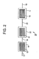
- the NO 2 trap material in the form of a layer deposited on a separate flow through carrier (21) that is interposed and in train with an upstream diesel oxidation catalyst (12) and a downstream soot filter (15).
- Exhaust gases flow from the engine to the canister (16) housing the diesel oxidation catalyst through the engine exhaust gas line (17).
- the diesel oxidation catalyst (12) From the diesel oxidation catalyst (12) the exhaust gases flow through an upstream exhaust gas line (19) to a canister (22) housing the flow through carrier (21) with the low temperature NO 2 trap material.
- the carrier (21) is a ceramic or metallic carrier having a plurality of channels along its longitudinal axis.
- the exhaust gases flow through a downstream exhaust gas line (13) to a canister (11) housing a soot filter (15).
- a soot filter 15
- An exhaust gas line (18) vents the treated exhaust from the soot filter to a muffler (not shown) and then to the atmosphere.
- the trap material and the soot filter are housed in the same canister (11) in the diesel engine exhaust train (10).
- the canister (11) is placed downstream of the diesel oxidation catalyst (12).
- Exhaust gases flow from the engine to the canister (16) housing the diesel oxidation catalyst through the engine exhaust gas line (17).
- the diesel oxidation catalyst (12) From the diesel oxidation catalyst (12) the exhaust gases flow through the exhaust gas line (13) to a canister (11) housing both a separate carrier (14) coated with NO 2 trap material and a soot filter (15).
- the NO 2 trap is formed by coating a carrier (e.g, ceramic monolith carrier) with a washcoat composition containing the trap material.
- the NO 2 trap is placed immediately adjacent to and upstream of the soot filter.
- the released NO 2 can be utilized as an oxidant to combust the soot in the soot filter.
- An exhaust gas line (18) vents the treated exhaust from the soot filter to a mutter and then to the atmosphere.
- a layer (32) containing a catalyst effective for the oxidation of soot can be deposited on the upstream side of the walls of the soot filter (33) as depicted in the sectional view of the soot filter in Figure 4 .
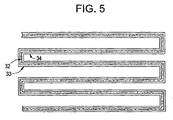
- the downstream side of the soot filter may remain uncoated as depicted in Figure 4 , or the downstream side of the soot filter can be coated with a catalyst washcoat composition (34) (preferably containing platinum group metals), effective to combust unburned hydrocarbons and carbon monoxide, as depicted in the sectional view of the soot filter in Figure 5 .
- This alternate coating architecture depicted in Figure 5 has the advantage that carbon monoxide produced during the combustion of the soot is converted to carbon dioxide (catalyzed by the platinum group metals deposited on the downstream side of the channel of the soot filter) before being emitted to the atmosphere.
- the channel walls (32) remain uncoated on the upstream side, and the downstream side of the channel walls contain a catalyst layer (34) as depicted in Figure 6 .
- the coating architectures depicted in Figure 5 or 6 can also be used to deposit a lean NOx catalyst composition on the soot filter.
- a washcoat containing platinum doped ZSM-5 can be deposited on the downstream side of the channel walls of the soot filter to aid in the combustion of unburned hydrocarbons.
- the hydrocarbons and NO 2 are trapped in the zeolite material deposited on a carrier upstream of the soot filter at cooler exhaust temperatures. As the temperature rises, the hydrocarbons and NO 2 are released, pass through the soot filter walls, and are reacted in the layer containing the lean NOx catalyst deposited on the downstream side of the channel walls.
- the upstream axial end of the soot filter is dipped into a reservoir containing a washcoat composition containing a desired catalyst material.
- the volume of the coating slurry is adjusted so that the level of the liquid in the reservoir remains below the downstream axial end of the soot filter. This precaution ensures that only the upstream side of the channel walls of the soot filter are coated with the desired catalyst material.
- the soot filter is then typically dried and calcined.
- the coated soot filter described in Figure 4 is further processed.
- the downstream axial end of the soot filter is dipped into a reservoir containing a washcoat containing a second catalyst composition.
- the volume of the coating slurry in the reservoir is adjusted so that the level of the liquid is below the upstream axial end of the soot filter to ensure that only the downstream side of the channel walls are coated with the second catalyst composition.
- the soot filter is then dried and calcined.
- the low temperature NO 2 trap materials of the invention can also be used in other applications where the removal of NO 2 from an inlet gas stream is desirable.
- the trap materials can be used for removing NO 2 from flue gases and other stationary sources.
- the trap materials can conveniently be regenerated by heating to temperatures effective to release the adsorbed NO 2 .
- the trap materials are referred to herein as "% M/zeolite".
- the "%M” refers to the weight percentage of the exchanged metal cation relative to the weight of the combined metal and zeolite.
- the "zeolite” refers to the specific zeolite used in the composition.
- a 3% Mn/ETS-10 zeolite refers to ETS-10 zeolite material containing 3% by weight of manganese cation.
- concentrations of the individual components of the test gas compositions are referred to in the examples as either percentage by volume or parts-per-million (ppm) of the test gas composition.
- the low temperature NO 2 trap materials were prepared using the following general procedure: A metal salt solution containing the metal to be exchanged, is prepared in about 300 g of water to give a predetermined amount of the metal on the corresponding zeolites. 100 g of ammonium form zeolite was then added to the metal salt solution and stirred for 2 hours at ambient conditions. After 2 hours a predetermined amount of ammonium hydroxide solution was added to precipitate the excess metal in the solution (pH about 8-9). The exchanged zeolite was then filtered out and washed with about 500 mL of water. The filtrate was then made into a slurry using about 10 g of alumina as a binder.
- the slurry contained about 30-35% solids, and was coated onto 0.5"x 1.0" cordierite ceramic 400 cpsi carriers to achieve a loading of 2 g/in 3 .
- the coated carriers were then dried at 100 °C for 2 hours and calcined at 550 °C for 1 hour in dry air. This procedure was used to prepare 3% Mn/ZSM-5, 3% Mn/ETS-10, 3% Mn 3%Co/ETS-10, 5% Fe/ZSM-5, 3% Cu/ZSM-5, and 3% Mn/Y zeolite.
- the corresponding metal solution e.g., Co or Mn nitrate salt solutions
- a desired metal concentration in the zeolite was used to incorporate a desired metal concentration in the zeolite using the same procedure outlined above.
- a honeycomb carrier of 0.5 in diameter with a 1 in length was packed tightly in a quartz reactor where a gas feed with a total flow of about 1-1.5 L/min was introduced, usually at room temperature, to give a GHSV of about 30,000-45,000 hr -1 .
- the gas composition of the feed typically contained 250 ppm NO 2 , 1000 ppm Cl as toluene or propylene, 20 ppm SO 2 , 1.5% water, 5% O 2 and the balance was N 2 .
- the level of water depended upon the procedure used and will be indicated in each example. To obtain 1.5% water, air was bubbled into a 1 L container kept at room temperature to achieve complete saturation (100% humidity).
- the 10% steam in the feed was obtained using a syringe pump. Detection of the NOx in the outlet gas stream was achieved by chemiluminescence techniques. The disappearance of NO 2 was measured relative to the amount of fed NOx (NOx in -NOx out /NOx in * 100).
- ETS-10 is a titanium silicate type molecular sieve whose preparation is described in United States Patent Nos. 4,853,202 and 5,244,650 , herein incorporated by reference. These are large port size molecular sieves.
- Figure 7 shows the NO 2 storage and.release of a 3 wt. % Mn exchanged ETS-10 trap (Mn/ETS-10) material coated on honeycomb carrier in a gas stream containing NO 2 with increasing time.
- the gas feed contained water saturated air (about 1.5% water), 250 ppm NO 2 , 1000 ppm toluene , 20 ppm SO 2 , 15% O 2 and the balance was N 2 .
- the gas feed was introduced into the reactor at about 30 °C.
- the temperature of the gas feed was increased at a rate of 13 °C/min from ambient (about 25 °C) to about 450 °C over a 30 minute time period.
- the left ordinate corresponds to the percentage disappearance of the NOx and the toluene
- the right ordinate corresponds to the inlet temperature
- the abscissa corresponds to the time in minutes.
- the solid curve represents the inlet temperature
- the curve containing squares represents the NOx
- the curve containing the circles represents the toluene.
- the Mn/ETS-10 trap material shows NO 2 absorbance at 30 to 120 °C with an efficiency of over 60% for a period of about 5 minutes.
- the NO 2 adsorption efficiency dropped with increasing catalyst temperature to 150 °C.
- the NO 2 was released at temperatures greater than 150 °C with a maximum release efficiency of 100% (measured at -100%) occurring at 200 °C.
- Complete regeneration of the trap occurred at about 240 °C.
- the honeycomb monolith coated with the Mn/ETS-10 trap material adsorbs NO 2 from a gas stream containing NO 2 with an efficiency of 60% over a 10 minute period.
- the trapping efficiency was reduced as the trap became saturated, with trapping efficiency dropping to 0 after 20 minutes.
- the data clearly demonstrated that the trap material had high NO 2 trapping efficiency over a period of 20 minutes.
- the temperature of the feed gas was increased at a rate of 13 °C/min to a temperature of 450 °C.
- NOx release was observed to occur at about 140 °C, and regeneration of the trap was complete after less than 10 minutes at about 240 °C.
- the rate of NOx release depended on the inlet temperature.
- Maximum NOx release efficiency of 100% over the Mn/ETS-10 was observed at 200 °C. The release of the NO 2 and the regeneration of the trap were therefore demonstrated.
- the capability of the Mn/ETS-10 trap material to trap and release NO 2 was also demonstrated by performing several regeneration cycles over the same catalyst carrier.
- Example 4 Storage and Release Properties of a 3% Co 3% Mn/ETS-10 Trap
- Example 3 3% Co 3% Mn/ETS-10 material was prepared and coated onto a monolith carrier as described in Example 1.
- the test gas composition contained water saturated air (about 1.5% water), 250 ppm NO 2 , 1000 ppm toluene, 20 ppm SO 2 , 15% O 2 and the balance was N 2 .
- the space velocity of the gas feed was 30,000 hr -1 .
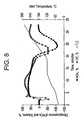
- FIG. 9 The trapping and release efficiencies of a CoMn/ETS-10 trap material coated on a honeycomb substrate from ambient (25 °C) to 450 °C is presented in Figure 9 .
- the left ordinate corresponds to the percentage disappearance of the NOx and toluene
- the right ordinate corresponds to the inlet temperature
- the abscissa corresponds to the time in minutes.
- the solid curve represents the inlet temperature
- the curve containing squares represents the NOx
- the curve containing the circles represents the toluene.
- the 3% Co 3% Mn/ETS-10 material had about the same NO 2 trapping efficiency, however, the temperature at which the NO 2 was released was increased from 140 to 160 °C.
- the temperature of the feed gas containing water-saturated air, i.e., about 1.5% water
- the NO 2 was trapped with an efficiency of 60% over 10 minutes ( Figure 9 ).
- the NO 2 trapping efficiency drops to 0 at 160 °C.
- the NO 2 was released at temperatures greater than 160 °C with a maximum release efficiency of 70% (measured at -70%) occurring at 200 °C.
- the trap was completely regenerated at about 300 °C.
- the complete release of the NO 2 from the trap occured at temperature ranges that are practically achieved in diesel engine exhaust platforms. In diesel engine exhaust systems, the released NO 2 could be used, for example, to combust soot deposited on a soot filter.
- the NO 2 trapping efficiency was about 40-50% of the inlet NO 2 for over 40 minutes.
- This data demonstrated the Co/Mn/ETS-10 material showed good trapping capacity.
- the stored NO 2 was released with increasing in reactor temperature and the NO 2 was completely released at 300 °C.
- the properties of the CoMn/ETS-10 material appear to be well-suited for both the effective storage of NO 2 , and release of the stored NO 2 at temperatures convenient to burn the soot trapped on a soot filter.
- Example 5 Storage and Release Properties of a 3%Mn/Y-zeolite Trap
- a monolith carrier coated with 3% Mn/Y-zeolite trap material was prepared according to Example 1.
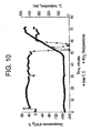
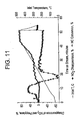
- the trapping and release efficiencies of the 3% Mn/Y-zeolite trap material coated on a honeycomb substrate from ambient (25 °C) to 450 °C was examined, and the results are displayed in Figure 11 .
- the feed gas contained 250 ppm of NO 2 , 333 ppm propylene, 25 ppm SO 2 , and 10% steam, 12% O 2 , and the balance was N 2 .
- the space velocity was 25,000 hr -1 .
- the inlet temperature of the feed gas was increased at 13 °/min from ambient to 450 °C.
- the left ordinate corresponds to the percentage disappearance of the NOx and the propylene
- the right ordinate corresponds to the inlet temperature (in °C)
- the abscissa corresponds to the time (in minutes).
- the solid curve represents the inlet temperature
- the curve containing the circles represents the NOx
- the curve containing the inverted triangles represents the propylene.
- the NO 2 was trapped with an efficiency of 50% in the temperature range of 75 to 1 50 °C.
- the NO 2 trapping efficiency drops to 0% at 170 °C.
- the NO 2 was released at temperatures greater than 170 °C with a maximum release efficiency of 90% (measured at -90%) occurring at 200 °C.
- the NO 2 storage and release properties of the 3% Mn/Y-zeolite trap material appear to be well-suited for the regeneration of a soot filter in a diesel engine exhaust system.
- Example 6 NO 2 Reduction Using A System Having an Upstream 3% Mn/Y-zeolite Trap and a Downstream Pt/ZSM-5 Zeolite NOx Catalyst
- the performance of a system containing two monolith carriers was determined.
- the monolith carrier coated with the 10% Mn/Y zeolite composition was placed upstream of a second monolith carrier coated with a washcoat composition of platinum exchanged on ZSM-5 zeolite material (referred to as Pt/ZSM-5 material).
- the Pt/ZSM-5 catalyst was prepared as follows: 11.7 g of platinum hydroxide as amine solubilized monoethanolamine platinum complex (MEA) x Pt(OH) 6 was diluted in water to a total solution weight of 156 g.
- ZSM-5 was added and mixed for about 30 minutes.
- 15 g of acetic acid and 30.29 g of silica sol (Nalco 1056) was added as binder.
- the slurry was ballmilled until a slurry having 90% of the particles with a particle size of less than 10 microns was achieved.
- a ceramic substrate of 0.5 in x 1.0 in dimension was coated with the slurry to a level of about 2 g/in 3 by applying the slurry twice, drying and calcining in between. The coated catalyst was then dried and calcined at 550 °C for 2 hours.
- the system was exposed to a test gas composition with a space velocity of 25,000 hr -1 .
- the test gas composition was composed of 250 ppm NO 2 , 1000 ppm propylene, 25 ppm SO 2 , 10% steam, 10% O 2 . and the balance was nitrogen.
- the results of the experiment are graphically represented in Figure 12 , the left ordinate corresponds to the percentage disappearance of the NOx and the propylene, the right ordinate corresponds to the inlet temperature (in °C) and the abscissa displays the time (in minutes).
- the solid line represents the inlet temperature, the line with the circles shows the NO 2 disappearance and the line with the inverted triangles shows the propylene disappearance.
- the NO 2 disappearance was better than 40% in the temperature range of 70 to 150 °C. As temperature increased, some of the trapped NO 2 was released. At 200 °C, the released NO 2 was reduced.
- This experiment demonstrates the ability of the released NO 2 to be successfully used as an oxidant to oxidize a substrate material (in this case, propylene) at temperature ranges above 200 °C.
- a substrate material in this case, propylene
- the NO 2 released could be utilized to oxidize the soot deposited on a soot filter.
Landscapes
- Chemical & Material Sciences (AREA)
- Engineering & Computer Science (AREA)
- Combustion & Propulsion (AREA)
- Chemical Kinetics & Catalysis (AREA)
- General Engineering & Computer Science (AREA)
- Mechanical Engineering (AREA)
- Materials Engineering (AREA)
- Organic Chemistry (AREA)
- Crystallography & Structural Chemistry (AREA)
- Analytical Chemistry (AREA)
- Environmental & Geological Engineering (AREA)
- General Chemical & Material Sciences (AREA)
- Oil, Petroleum & Natural Gas (AREA)
- Biomedical Technology (AREA)
- Health & Medical Sciences (AREA)
- Exhaust Gas After Treatment (AREA)
- Catalysts (AREA)
- Exhaust Gas Treatment By Means Of Catalyst (AREA)
- Processes For Solid Components From Exhaust (AREA)
- Filtering Of Dispersed Particles In Gases (AREA)
- Silicates, Zeolites, And Molecular Sieves (AREA)
- Solid-Sorbent Or Filter-Aiding Compositions (AREA)
Applications Claiming Priority (2)
| Application Number | Priority Date | Filing Date | Title |
|---|---|---|---|
| US10/032,200 US6912847B2 (en) | 2001-12-21 | 2001-12-21 | Diesel engine system comprising a soot filter and low temperature NOx trap |
| EP02797265A EP1456511A2 (de) | 2001-12-21 | 2002-12-11 | Abgassystem und verfahren zur entfernung von festteilchen aus dem abgas eines dieselmotors |
Related Parent Applications (1)
| Application Number | Title | Priority Date | Filing Date |
|---|---|---|---|
| EP02797265A Division EP1456511A2 (de) | 2001-12-21 | 2002-12-11 | Abgassystem und verfahren zur entfernung von festteilchen aus dem abgas eines dieselmotors |
Publications (2)
| Publication Number | Publication Date |
|---|---|
| EP2048115A2 true EP2048115A2 (de) | 2009-04-15 |
| EP2048115A3 EP2048115A3 (de) | 2009-07-29 |
Family
ID=21863638
Family Applications (2)
| Application Number | Title | Priority Date | Filing Date |
|---|---|---|---|
| EP09075049A Withdrawn EP2048115A3 (de) | 2001-12-21 | 2002-12-11 | Zeolithzusammensetzung |
| EP02797265A Withdrawn EP1456511A2 (de) | 2001-12-21 | 2002-12-11 | Abgassystem und verfahren zur entfernung von festteilchen aus dem abgas eines dieselmotors |
Family Applications After (1)
| Application Number | Title | Priority Date | Filing Date |
|---|---|---|---|
| EP02797265A Withdrawn EP1456511A2 (de) | 2001-12-21 | 2002-12-11 | Abgassystem und verfahren zur entfernung von festteilchen aus dem abgas eines dieselmotors |
Country Status (6)
| Country | Link |
|---|---|
| US (1) | US6912847B2 (de) |
| EP (2) | EP2048115A3 (de) |
| JP (1) | JP2005514551A (de) |
| KR (1) | KR20040077683A (de) |
| AU (1) | AU2002362131A1 (de) |
| WO (1) | WO2003056150A2 (de) |
Families Citing this family (107)
| Publication number | Priority date | Publication date | Assignee | Title |
|---|---|---|---|---|
| US20020007629A1 (en) * | 2000-07-21 | 2002-01-24 | Toyota Jidosha Kabushiki Kaisha | Device for purifying the exhaust gas of an internal combustion engine |
| AU2001293841A1 (en) * | 2000-09-29 | 2002-04-08 | Omg Ag And Co. Kg | Catalytic soot filter and use thereof in treatment of lean exhaust gases |
| WO2003011437A1 (en) * | 2001-08-01 | 2003-02-13 | Johnson Matthey Public Limited Company | Gasoline engine with an exhaust system for combusting particulate matter |
| US20030101718A1 (en) * | 2001-10-06 | 2003-06-05 | Marcus Pfeifer | Method and device for the catalytic conversion of gaseous pollutants in the exhaust gas of combustion engines |
| EP1312776A3 (de) * | 2001-11-16 | 2004-05-12 | Isuzu Motors Limited | Abgasreinigungsvorrichtung |
| JP2003206733A (ja) * | 2002-01-16 | 2003-07-25 | Hitachi Ltd | 内燃機関用排気ガス浄化装置 |
| GB0206613D0 (en) * | 2002-03-21 | 2002-05-01 | Johnson Matthey Plc | Exhaust system for an internal combustion engine |
| DE10214343A1 (de) * | 2002-03-28 | 2003-10-09 | Omg Ag & Co Kg | Partikelfilter mit einer katalytisch aktiven Beschichtung zur Beschleunigung der Verbrennung der auf dem Filter gesammelten Rußpartikel während einer Regenerationsphase |
| GB0218540D0 (en) * | 2002-08-09 | 2002-09-18 | Johnson Matthey Plc | Engine exhaust treatment |
| WO2004018850A1 (ja) * | 2002-08-26 | 2004-03-04 | Hitachi, Ltd. | ディーゼルエンジンの排気ガス浄化装置および排気ガス浄化方法 |
| ES2239187T3 (es) * | 2002-08-27 | 2005-09-16 | Audi Ag | Procedimiento para calentar filtro de hollin en sistema de gases de escape de un motor de combustion interna -en particular un motor diesel- con al menos un catalizador y un filtro de hollin dispuesto aguas abajo de estos en la direccion de salida, a fin de almacenar el hollin. |
| JP2005538300A (ja) * | 2002-09-13 | 2005-12-15 | ジョンソン、マッセイ、パブリック、リミテッド、カンパニー | 圧縮着火機関およびそのための排気機構 |
| US6925853B2 (en) * | 2002-10-24 | 2005-08-09 | Midwest Research Institute | Air quality sampler using solid phase coated material |
| US7582270B2 (en) | 2002-10-28 | 2009-09-01 | Geo2 Technologies, Inc. | Multi-functional substantially fibrous mullite filtration substrates and devices |
| US7574796B2 (en) | 2002-10-28 | 2009-08-18 | Geo2 Technologies, Inc. | Nonwoven composites and related products and methods |
| US6946013B2 (en) | 2002-10-28 | 2005-09-20 | Geo2 Technologies, Inc. | Ceramic exhaust filter |
| US7572311B2 (en) | 2002-10-28 | 2009-08-11 | Geo2 Technologies, Inc. | Highly porous mullite particulate filter substrate |
| DE10300298A1 (de) * | 2003-01-02 | 2004-07-15 | Daimlerchrysler Ag | Abgasnachbehandlungseinrichtung und -verfahren |
| KR100469066B1 (ko) * | 2003-04-14 | 2005-02-02 | 에스케이 주식회사 | 디젤차량 입자상 물질 제거용 필터 및 이의 제조방법 |
| DE10322148B4 (de) * | 2003-05-16 | 2006-11-02 | Umicore Ag & Co. Kg | Abgasreinigungsanlage mit Partikelfilter und Verfahren zu ihrem Betrieb mit verbesserter Regeneration des Partikelfilters |
| JP4158697B2 (ja) * | 2003-06-17 | 2008-10-01 | トヨタ自動車株式会社 | 内燃機関の排気浄化装置および排気浄化方法 |
| US7229597B2 (en) | 2003-08-05 | 2007-06-12 | Basfd Catalysts Llc | Catalyzed SCR filter and emission treatment system |
| JP4006645B2 (ja) * | 2003-08-27 | 2007-11-14 | トヨタ自動車株式会社 | 排ガス浄化装置 |
| RU2350379C2 (ru) * | 2003-08-29 | 2009-03-27 | Дау Глобал Текнолоджиз Инк. | Фильтр для выхлопных газов дизельных двигателей |
| US20050100494A1 (en) | 2003-11-06 | 2005-05-12 | George Yaluris | Ferrierite compositions for reducing NOx emissions during fluid catalytic cracking |
| JP2005224682A (ja) * | 2004-02-12 | 2005-08-25 | Hitachi Ltd | 内燃機関用排ガス浄化装置及び排ガス浄化方法 |
| JP4218556B2 (ja) * | 2004-03-11 | 2009-02-04 | トヨタ自動車株式会社 | 内燃機関排気浄化装置の粒子状物質再生制御装置 |
| DE102004024519A1 (de) | 2004-05-18 | 2005-12-15 | Adam Opel Ag | Minimierung von PAK-Emissionen bei der Regeneration von Partikelfiltern |
| US7238332B2 (en) * | 2004-06-14 | 2007-07-03 | Feaver William B | Material and process for the filtration of nitric acid and NO2 from streams of air |
| JP2006077591A (ja) * | 2004-09-07 | 2006-03-23 | Hino Motors Ltd | 排気浄化装置 |
| US7146802B2 (en) * | 2004-10-07 | 2006-12-12 | General Motors Corporation | Reducing NOx emissions with a staged catalyst |
| DE102004000044B4 (de) * | 2004-11-17 | 2013-08-29 | Mann + Hummel Gmbh | Luftfiltersystem |
| US20060168949A1 (en) * | 2005-02-02 | 2006-08-03 | Lifeng Xu | Alumina-based lean NOx trap system and method of use in dual-mode HCCI engines |
| US20060168948A1 (en) * | 2005-02-02 | 2006-08-03 | Lifeng Xu | Alumina-based lean NOx trap system and method of use |
| US20060179825A1 (en) * | 2005-02-16 | 2006-08-17 | Eaton Corporation | Integrated NOx and PM reduction devices for the treatment of emissions from internal combustion engines |
| US7918991B2 (en) * | 2005-04-27 | 2011-04-05 | W. R. Grace & Co.-Conn. | Compositions and processes for reducing NOx emissions during fluid catalytic cracking |
| US7533524B2 (en) * | 2005-05-18 | 2009-05-19 | Cummins Inc. | Method and apparatus for soot filter catalyst temperature control with oxygen flow constraint |
| US20070251223A1 (en) * | 2005-07-07 | 2007-11-01 | Toyota Jidosha Kabushiki Kaisha | Exhaust Gas Control Apparatus for Internal Combustion Engine |
| US8209962B2 (en) * | 2005-09-28 | 2012-07-03 | Detroit Diesel Corporation | Diesel particulate filter soot permeability virtual sensors |
| DE102005049655A1 (de) * | 2005-10-18 | 2007-04-19 | Man Nutzfahrzeuge Ag | Verfahren zur Vermeidung von unerwünschten NO2-Emissionen bei Brennkraftmaschinen |
| KR100871898B1 (ko) | 2005-10-28 | 2008-12-05 | 에스케이에너지 주식회사 | 디젤 엔진의 배기가스 정화 장치 |
| US7211232B1 (en) | 2005-11-07 | 2007-05-01 | Geo2 Technologies, Inc. | Refractory exhaust filtering method and apparatus |
| US7682578B2 (en) | 2005-11-07 | 2010-03-23 | Geo2 Technologies, Inc. | Device for catalytically reducing exhaust |
| US7451849B1 (en) | 2005-11-07 | 2008-11-18 | Geo2 Technologies, Inc. | Substantially fibrous exhaust screening system for motor vehicles |
| US7682577B2 (en) | 2005-11-07 | 2010-03-23 | Geo2 Technologies, Inc. | Catalytic exhaust device for simplified installation or replacement |
| JP4270224B2 (ja) * | 2005-11-09 | 2009-05-27 | トヨタ自動車株式会社 | 内燃機関の排気浄化装置 |
| US8119075B2 (en) * | 2005-11-10 | 2012-02-21 | Basf Corporation | Diesel particulate filters having ultra-thin catalyzed oxidation coatings |
| US7506504B2 (en) * | 2005-12-21 | 2009-03-24 | Basf Catalysts Llc | DOC and particulate control system for diesel engines |
| US7992375B2 (en) * | 2005-12-27 | 2011-08-09 | Chevron U.S.A. Inc. | Treatment of engine exhaust using molecular sieve SSZ-73 |
| US7722828B2 (en) | 2005-12-30 | 2010-05-25 | Geo2 Technologies, Inc. | Catalytic fibrous exhaust system and method for catalyzing an exhaust gas |
| US7444805B2 (en) | 2005-12-30 | 2008-11-04 | Geo2 Technologies, Inc. | Substantially fibrous refractory device for cleaning a fluid |
| US7343736B2 (en) | 2006-02-27 | 2008-03-18 | Detroit Diesel Corporation | Flexible exhaust emission aftertreatment system for compression cycle diesel engines |
| US7563415B2 (en) | 2006-03-03 | 2009-07-21 | Geo2 Technologies, Inc | Catalytic exhaust filter device |
| JP2007245050A (ja) * | 2006-03-17 | 2007-09-27 | Toyota Central Res & Dev Lab Inc | 窒素酸化物吸着材、その製造方法、及びそれを用いた窒素酸化物の除去方法 |
| JP2007291981A (ja) * | 2006-04-26 | 2007-11-08 | Hino Motors Ltd | 排気浄化装置 |
| JP2007291980A (ja) * | 2006-04-26 | 2007-11-08 | Hino Motors Ltd | 排気浄化装置 |
| US7576031B2 (en) * | 2006-06-09 | 2009-08-18 | Basf Catalysts Llc | Pt-Pd diesel oxidation catalyst with CO/HC light-off and HC storage function |
| US7434387B2 (en) | 2006-07-26 | 2008-10-14 | Eaton Corporation | Integrated DPF-reformer |
| US7614214B2 (en) | 2006-07-26 | 2009-11-10 | Eaton Corporation | Gasification of soot trapped in a particulate filter under reducing conditions |
| GB0617070D0 (en) | 2006-08-30 | 2006-10-11 | Johnson Matthey Plc | Low Temperature Hydrocarbon SCR |
| US20080078171A1 (en) * | 2006-09-29 | 2008-04-03 | Dacosta Herbert F M | Chemically functionalized filter system |
| US7550126B2 (en) * | 2007-01-25 | 2009-06-23 | Southwest Research Institute | NOx augmentation in exhaust gas simulation system |
| US7810315B2 (en) * | 2007-02-20 | 2010-10-12 | Eaton Corporation | LNT regeneration strategy to reduce NOx spike |
| US20080196398A1 (en) * | 2007-02-20 | 2008-08-21 | Eaton Corporation | HC mitigation to reduce NOx spike |
| JP4349425B2 (ja) * | 2007-03-19 | 2009-10-21 | 日産自動車株式会社 | NOx触媒の診断装置 |
| JP2008264702A (ja) | 2007-04-20 | 2008-11-06 | Toyota Motor Corp | NOx吸着材の製造方法及びNOx吸着材 |
| DE102007032734A1 (de) * | 2007-07-13 | 2009-01-15 | Emitec Gesellschaft Für Emissionstechnologie Mbh | Verfahren zur Regeneration wenigstens eines Partikelagglomerators sowie Kraftfahrzeug umfassend eine Abgasnachbehandlungsanlage |
| JP5590640B2 (ja) * | 2007-08-01 | 2014-09-17 | 日産自動車株式会社 | 排気ガス浄化システム |
| JP4849034B2 (ja) * | 2007-08-08 | 2011-12-28 | マツダ株式会社 | 触媒付パティキュレートフィルタ |
| US7806956B2 (en) * | 2007-08-09 | 2010-10-05 | Cummins Filtration Ip, Inc. | Tuning particulate filter performance through selective plugging and use of multiple particulate filters to reduce emissions and improve thermal robustness |
| EP2318673B1 (de) * | 2008-02-05 | 2019-09-18 | BASF Corporation | Partikelfilter aufweisende systeme zur behandlung von benzinmotoremissionen |
| KR101251499B1 (ko) * | 2008-12-05 | 2013-04-05 | 오덱(주) | 질소 산화물 제거용 제올라이트 촉매, 이의 제조 방법 및 이를 이용한 질소 산화물 제거 방법 |
| DE102009000208A1 (de) * | 2009-01-14 | 2010-07-15 | Robert Bosch Gmbh | Bauelement, insbesondere Dieselpartikelfilter, mit einer oxidischen Beschichtung |
| US8231701B2 (en) * | 2009-01-21 | 2012-07-31 | Corning Incorporated | Particulate filters and methods for regenerating particulate filters |
| US8097554B2 (en) * | 2009-02-09 | 2012-01-17 | Airflow Catalyst Systems, Inc. | Apparatus for removing soot from diesel engine exhaust streams at temperatures at or below 150° C. |
| GB0903262D0 (en) * | 2009-02-26 | 2009-04-08 | Johnson Matthey Plc | Filter |
| JP2010227767A (ja) * | 2009-03-26 | 2010-10-14 | Ngk Insulators Ltd | ハニカムフィルタ |
| CN105749747A (zh) | 2009-04-17 | 2016-07-13 | 约翰逊马西有限公司 | 小孔分子筛负载铜催化剂 |
| US8596063B2 (en) * | 2009-06-18 | 2013-12-03 | GM Global Technology Operations LLC | Exhaust treatment system for an internal combustion engine |
| JP5531501B2 (ja) * | 2009-08-21 | 2014-06-25 | 三菱自動車工業株式会社 | 排ガス浄化装置 |
| US9657625B2 (en) * | 2009-11-13 | 2017-05-23 | Basf Corporation | Wall flow filter loaded with SCR catalyst, systems and methods of exhaust gas treatment |
| GB2478132A (en) * | 2010-02-25 | 2011-08-31 | Gm Global Tech Operations Inc | Device to reduce NOx for all driving profiles at both low and high exhaust temperatures. |
| JP4998579B2 (ja) * | 2010-04-01 | 2012-08-15 | トヨタ自動車株式会社 | 排気浄化触媒 |
| US8815189B2 (en) | 2010-04-19 | 2014-08-26 | Basf Corporation | Gasoline engine emissions treatment systems having particulate filters |
| JP2012077693A (ja) * | 2010-10-01 | 2012-04-19 | Mitsubishi Motors Corp | 排気浄化装置 |
| US8845974B2 (en) * | 2010-11-24 | 2014-09-30 | Basf Corporation | Advanced catalyzed soot filters and method of making and using the same |
| US20120124976A1 (en) * | 2010-11-24 | 2012-05-24 | Airflow Catalyst Systems, Inc. | Apparatus for removing mixed nitrogen oxides, carbon monoxide, hydrocarbons and diesel particulate matter from diesel engine exhaust streams at temperatures at or below 280 degrees c |
| KR20120095747A (ko) * | 2011-02-21 | 2012-08-29 | 한국에너지기술연구원 | 다기능성 배기가스 정화필터 및 이를 이용한 배기가스 정화장치 |
| US20120308439A1 (en) | 2011-06-01 | 2012-12-06 | Johnson Matthey Public Limited Company | Cold start catalyst and its use in exhaust systems |
| US10226762B1 (en) * | 2011-06-17 | 2019-03-12 | Johnson Matthey Public Limited Company | Alumina binders for SCR catalysts |
| KR101724453B1 (ko) * | 2011-07-13 | 2017-04-10 | 현대자동차 주식회사 | 배기 가스 정화 장치 및 이를 제어하는 방법 |
| KR101684496B1 (ko) | 2011-09-09 | 2016-12-09 | 현대자동차 주식회사 | 배기가스 정화 장치 및 이를 제어하는 방법 |
| US8997461B2 (en) | 2012-05-21 | 2015-04-07 | Cummins Emission Solutions Inc. | Aftertreatment system having two SCR catalysts |
| WO2014125305A1 (en) | 2013-02-18 | 2014-08-21 | Johnson Matthey Public Limited Company | NOx TRAP COMPOSITION |
| CN105792914A (zh) | 2013-12-06 | 2016-07-20 | 庄信万丰股份有限公司 | 冷启动催化剂和其在排气系统中的用途 |
| GB2522977B (en) * | 2013-12-06 | 2017-02-08 | Johnson Matthey Plc | Passive NOx adsorber |
| DE102015000955B4 (de) | 2014-01-20 | 2025-01-23 | Cummins Inc. | Systeme und Verfahren zur Minderung von NOx- und HC-Emissionen |
| US9512761B2 (en) | 2014-02-28 | 2016-12-06 | Cummins Inc. | Systems and methods for NOx reduction and aftertreatment control using passive NOx adsorption |
| US9567888B2 (en) | 2014-03-27 | 2017-02-14 | Cummins Inc. | Systems and methods to reduce reductant consumption in exhaust aftertreament systems |
| CN103949283B (zh) * | 2014-04-12 | 2016-07-06 | 北京工业大学 | 一种用于SCR反应的Mn-ETS-10催化剂的合成方法 |
| SE539523C2 (en) | 2016-01-27 | 2017-10-10 | Scania Cv Ab | Exhaust gas treatment system |
| US10105691B2 (en) | 2016-03-31 | 2018-10-23 | Ford Global Technologies, Llc | Multiple zeolite hydrocarbon traps |
| KR102515969B1 (ko) * | 2016-07-22 | 2023-04-03 | 존슨 맛쎄이 퍼블릭 리미티드 컴파니 | 배기 가스 촉매 및 필터 기재에 대한 촉매 결합제 |
| MX2019009034A (es) | 2017-01-31 | 2019-11-21 | Corning Inc | Cuerpos de panal de abeja con patrón conectado, filtros de partículas y troqueles de extrusión de los mismos. |
| JP7615030B2 (ja) * | 2018-12-19 | 2025-01-16 | ビーエーエスエフ モバイル エミッションズ カタリスツ エルエルシー | 触媒物品ならびにそれを製造および使用する方法 |
| US10876450B2 (en) * | 2019-05-22 | 2020-12-29 | FEV Europe GmbH | Splitflow catalyst system |
| US20240214721A1 (en) * | 2022-12-27 | 2024-06-27 | Aac Technologies (Nanjing) Co., Ltd. | Molecular sieve material for sound absorption and method for preparing the same |
Citations (5)
| Publication number | Priority date | Publication date | Assignee | Title |
|---|---|---|---|---|
| US4853202A (en) | 1987-09-08 | 1989-08-01 | Engelhard Corporation | Large-pored crystalline titanium molecular sieve zeolites |
| US4902482A (en) | 1987-07-28 | 1990-02-20 | Faust Paul A | Device and receptacle for inhibiting contamination for infections waste |
| US4902487A (en) | 1988-05-13 | 1990-02-20 | Johnson Matthey, Inc. | Treatment of diesel exhaust gases |
| US5244650A (en) | 1989-06-29 | 1993-09-14 | Engelhard Corporation | Large-pored molecular sieves with charged octahedral titanium and charged tetrahedral aluminum sites |
| US5627124A (en) | 1991-11-26 | 1997-05-06 | Engelhard Corporation | Ceria-alumina oxidation catalyst |
Family Cites Families (25)
| Publication number | Priority date | Publication date | Assignee | Title |
|---|---|---|---|---|
| US6051040A (en) * | 1988-12-28 | 2000-04-18 | Clean Diesel Technologies, Inc. | Method for reducing emissions of NOx and particulates from a diesel engine |
| US5208006A (en) * | 1990-05-28 | 1993-05-04 | Engelhard Corporation | Large-pored molecular sieves containing at least one octahedral site comprising titanium and at least silicon as a tetrahedral site |
| JPH05168857A (ja) | 1991-12-17 | 1993-07-02 | Mitsubishi Heavy Ind Ltd | 燃焼排ガス中の窒素酸化物低減法 |
| JPH0679137A (ja) | 1992-09-03 | 1994-03-22 | Mitsubishi Heavy Ind Ltd | 希薄窒素酸化物含有空気の処理方法 |
| US6087295A (en) | 1992-12-14 | 2000-07-11 | Asec Manufacturing | Reduction of NOx in the exhaust gases from internal combustion engines containing excess oxygen |
| DE69434059T2 (de) | 1993-11-04 | 2006-02-23 | Enitecnologie S.P.A. | Katalysator zur Reduktion von NOx in Verbrennungsabgasen |
| US5776423A (en) | 1994-05-10 | 1998-07-07 | Engelhard Corporation | Trimetallic zeolite catalyst and method of NOx abatement using the same |
| US6080377A (en) * | 1995-04-27 | 2000-06-27 | Engelhard Corporation | Method of abating NOx and a catalytic material therefor |
| US5682740A (en) * | 1995-05-12 | 1997-11-04 | Isuzu Ceramics Research Institute Co., Ltd. | Diesel particulate filter apparatus |
| JP3358392B2 (ja) | 1995-06-15 | 2002-12-16 | トヨタ自動車株式会社 | ディーゼル機関の排気浄化装置 |
| US5874057A (en) | 1995-07-12 | 1999-02-23 | Engelhard Corporation | Lean NOx catalyst/trap method |
| JP3899534B2 (ja) | 1995-08-14 | 2007-03-28 | トヨタ自動車株式会社 | ディーゼル機関の排気浄化方法 |
| US5727385A (en) | 1995-12-08 | 1998-03-17 | Ford Global Technologies, Inc. | Lean-burn nox catalyst/nox trap system |
| US6038854A (en) * | 1996-08-19 | 2000-03-21 | The Regents Of The University Of California | Plasma regenerated particulate trap and NOx reduction system |
| DE19640161A1 (de) | 1996-09-28 | 1998-04-02 | Volkswagen Ag | NOx-Abgasreinigungsverfahren |
| WO1998048153A1 (en) * | 1997-04-24 | 1998-10-29 | Toyota Jidosha Kabushiki Kaisha | Exhaust emission control system for internal combustion engines |
| US6093378A (en) * | 1997-05-07 | 2000-07-25 | Engelhard Corporation | Four-way diesel exhaust catalyst and method of use |
| JP3228232B2 (ja) * | 1998-07-28 | 2001-11-12 | トヨタ自動車株式会社 | 内燃機関の排気浄化装置 |
| US6146602A (en) | 1999-02-08 | 2000-11-14 | Ford Global Technologies, Inc. | Mesoporous oxide molecular sieves for absorbing nitrogen oxides in oxidizing engine exhaust gas |
| US6182443B1 (en) | 1999-02-09 | 2001-02-06 | Ford Global Technologies, Inc. | Method for converting exhaust gases from a diesel engine using nitrogen oxide absorbent |
| EP1055806A3 (de) | 1999-05-28 | 2003-03-12 | Ford Global Technologies, Inc. | Stickoxidfalle und Partikelfilter für eine Brennkraftmaschine |
| US6167696B1 (en) * | 1999-06-04 | 2001-01-02 | Ford Motor Company | Exhaust gas purification system for low emission vehicle |
| FR2796985B1 (fr) | 1999-07-28 | 2002-09-06 | Renault | Systeme et procede de traitement des particules et des oxydes d'azote pour un moteur a combustion |
| GB9919013D0 (en) | 1999-08-13 | 1999-10-13 | Johnson Matthey Plc | Reactor |
| US6314722B1 (en) * | 1999-10-06 | 2001-11-13 | Matros Technologies, Inc. | Method and apparatus for emission control |
-
2001
- 2001-12-21 US US10/032,200 patent/US6912847B2/en not_active Expired - Lifetime
-
2002
- 2002-12-11 AU AU2002362131A patent/AU2002362131A1/en not_active Abandoned
- 2002-12-11 KR KR10-2004-7009860A patent/KR20040077683A/ko not_active Abandoned
- 2002-12-11 EP EP09075049A patent/EP2048115A3/de not_active Withdrawn
- 2002-12-11 WO PCT/US2002/039497 patent/WO2003056150A2/en not_active Ceased
- 2002-12-11 JP JP2003556648A patent/JP2005514551A/ja active Pending
- 2002-12-11 EP EP02797265A patent/EP1456511A2/de not_active Withdrawn
Patent Citations (5)
| Publication number | Priority date | Publication date | Assignee | Title |
|---|---|---|---|---|
| US4902482A (en) | 1987-07-28 | 1990-02-20 | Faust Paul A | Device and receptacle for inhibiting contamination for infections waste |
| US4853202A (en) | 1987-09-08 | 1989-08-01 | Engelhard Corporation | Large-pored crystalline titanium molecular sieve zeolites |
| US4902487A (en) | 1988-05-13 | 1990-02-20 | Johnson Matthey, Inc. | Treatment of diesel exhaust gases |
| US5244650A (en) | 1989-06-29 | 1993-09-14 | Engelhard Corporation | Large-pored molecular sieves with charged octahedral titanium and charged tetrahedral aluminum sites |
| US5627124A (en) | 1991-11-26 | 1997-05-06 | Engelhard Corporation | Ceria-alumina oxidation catalyst |
Also Published As
| Publication number | Publication date |
|---|---|
| KR20040077683A (ko) | 2004-09-06 |
| AU2002362131A1 (en) | 2003-07-15 |
| JP2005514551A (ja) | 2005-05-19 |
| US6912847B2 (en) | 2005-07-05 |
| WO2003056150A2 (en) | 2003-07-10 |
| US20030115859A1 (en) | 2003-06-26 |
| AU2002362131A8 (en) | 2003-07-15 |
| WO2003056150A3 (en) | 2003-12-04 |
| EP2048115A3 (de) | 2009-07-29 |
| EP1456511A2 (de) | 2004-09-15 |
Similar Documents
| Publication | Publication Date | Title |
|---|---|---|
| US6912847B2 (en) | Diesel engine system comprising a soot filter and low temperature NOx trap | |
| JP4497560B2 (ja) | フォーウエイディーゼル排気ガス触媒および使用方法 | |
| RU2609796C2 (ru) | Покрытая катализатором подложка и система выпуска выхлопных газов для двигателей внутреннего сгорания | |
| RU2658822C2 (ru) | Зонированный катализатор на монолитной подложке | |
| CA2629129C (en) | Diesel particulate filters having ultra-thin catalyzed oxidation coatings | |
| CN107405606B (zh) | 柴油机氧化催化剂 | |
| JP4147591B2 (ja) | 再生可能な触媒を用いた捕捉および装置そしてそれの使用方法 | |
| RU2692809C1 (ru) | Катализатор для холодного запуска и его применение в выхлопных системах | |
| US20080253950A1 (en) | Hydrothermally stable ag-zeolite traps for small olefin hydrocarbon molecules | |
| JP2018535818A (ja) | すす触媒とscr触媒を有する触媒フィルタ | |
| RU2747358C2 (ru) | КАТАЛИЗАТОР-АДСОРБЕР NOx | |
| WO2018078587A1 (en) | Catalytic and sorptive articles comprising metal fiber felt substrates | |
| KR20200055744A (ko) | 조합된 NOx 흡수제 및 SCR 촉매 | |
| JP7579260B2 (ja) | 窒素酸化物を還元するための触媒 | |
| JP2019520508A (ja) | 排気システム | |
| HK1026654B (en) | Four-way diesel exhaust catalyst and method of use |
Legal Events
| Date | Code | Title | Description |
|---|---|---|---|
| PUAI | Public reference made under article 153(3) epc to a published international application that has entered the european phase |
Free format text: ORIGINAL CODE: 0009012 |
|
| AC | Divisional application: reference to earlier application |
Ref document number: 1456511 Country of ref document: EP Kind code of ref document: P |
|
| AK | Designated contracting states |
Kind code of ref document: A2 Designated state(s): AT BE BG CH CY CZ DE DK EE ES FI FR GB GR IE IT LI LU MC NL PT SE SI SK TR |
|
| PUAL | Search report despatched |
Free format text: ORIGINAL CODE: 0009013 |
|
| AK | Designated contracting states |
Kind code of ref document: A3 Designated state(s): AT BE BG CH CY CZ DE DK EE ES FI FR GB GR IE IT LI LU MC NL PT SE SI SK TR |
|
| 17P | Request for examination filed |
Effective date: 20100129 |
|
| AKX | Designation fees paid |
Designated state(s): AT BE BG CH CY CZ DE DK EE ES FI FR GB GR IE IT LI LU MC NL PT SE SI SK TR |
|
| 17Q | First examination report despatched |
Effective date: 20100407 |
|
| STAA | Information on the status of an ep patent application or granted ep patent |
Free format text: STATUS: THE APPLICATION IS DEEMED TO BE WITHDRAWN |
|
| 18D | Application deemed to be withdrawn |
Effective date: 20100818 |