EP2006579B1 - Steuervorrichtung mit Schaltstellungsdetektor und Antriebsstrang mit der Steuervorrichtung - Google Patents
Steuervorrichtung mit Schaltstellungsdetektor und Antriebsstrang mit der Steuervorrichtung Download PDFInfo
- Publication number
- EP2006579B1 EP2006579B1 EP08164879.2A EP08164879A EP2006579B1 EP 2006579 B1 EP2006579 B1 EP 2006579B1 EP 08164879 A EP08164879 A EP 08164879A EP 2006579 B1 EP2006579 B1 EP 2006579B1
- Authority
- EP
- European Patent Office
- Prior art keywords
- shift position
- position detecting
- detecting device
- board
- control board
- Prior art date
- Legal status (The legal status is an assumption and is not a legal conclusion. Google has not performed a legal analysis and makes no representation as to the accuracy of the status listed.)
- Expired - Fee Related
Links
Images


Classifications
-
- F—MECHANICAL ENGINEERING; LIGHTING; HEATING; WEAPONS; BLASTING
- F16—ENGINEERING ELEMENTS AND UNITS; GENERAL MEASURES FOR PRODUCING AND MAINTAINING EFFECTIVE FUNCTIONING OF MACHINES OR INSTALLATIONS; THERMAL INSULATION IN GENERAL
- F16H—GEARING
- F16H59/00—Control inputs to control units of change-speed-, or reversing-gearings for conveying rotary motion
- F16H59/02—Selector apparatus
- F16H59/08—Range selector apparatus
-
- H—ELECTRICITY
- H05—ELECTRIC TECHNIQUES NOT OTHERWISE PROVIDED FOR
- H05K—PRINTED CIRCUITS; CASINGS OR CONSTRUCTIONAL DETAILS OF ELECTRIC APPARATUS; MANUFACTURE OF ASSEMBLAGES OF ELECTRICAL COMPONENTS
- H05K7/00—Constructional details common to different types of electric apparatus
- H05K7/02—Arrangements of circuit components or wiring on supporting structure
-
- F—MECHANICAL ENGINEERING; LIGHTING; HEATING; WEAPONS; BLASTING
- F16—ENGINEERING ELEMENTS AND UNITS; GENERAL MEASURES FOR PRODUCING AND MAINTAINING EFFECTIVE FUNCTIONING OF MACHINES OR INSTALLATIONS; THERMAL INSULATION IN GENERAL
- F16H—GEARING
- F16H59/00—Control inputs to control units of change-speed-, or reversing-gearings for conveying rotary motion
- F16H59/02—Selector apparatus
- F16H59/08—Range selector apparatus
- F16H59/10—Range selector apparatus comprising levers
- F16H59/105—Range selector apparatus comprising levers consisting of electrical switches or sensors
-
- F—MECHANICAL ENGINEERING; LIGHTING; HEATING; WEAPONS; BLASTING
- F16—ENGINEERING ELEMENTS AND UNITS; GENERAL MEASURES FOR PRODUCING AND MAINTAINING EFFECTIVE FUNCTIONING OF MACHINES OR INSTALLATIONS; THERMAL INSULATION IN GENERAL
- F16H—GEARING
- F16H61/00—Control functions within control units of change-speed- or reversing-gearings for conveying rotary motion ; Control of exclusively fluid gearing, friction gearing, gearings with endless flexible members or other particular types of gearing
- F16H61/0003—Arrangement or mounting of elements of the control apparatus, e.g. valve assemblies or snapfittings of valves; Arrangements of the control unit on or in the transmission gearbox
- F16H61/0006—Electronic control units for transmission control, e.g. connectors, casings or circuit boards
-
- H—ELECTRICITY
- H05—ELECTRIC TECHNIQUES NOT OTHERWISE PROVIDED FOR
- H05K—PRINTED CIRCUITS; CASINGS OR CONSTRUCTIONAL DETAILS OF ELECTRIC APPARATUS; MANUFACTURE OF ASSEMBLAGES OF ELECTRICAL COMPONENTS
- H05K5/00—Casings, cabinets or drawers for electric apparatus
- H05K5/0026—Casings, cabinets or drawers for electric apparatus provided with connectors and printed circuit boards [PCB], e.g. automotive electronic control units
- H05K5/0082—Casings, cabinets or drawers for electric apparatus provided with connectors and printed circuit boards [PCB], e.g. automotive electronic control units specially adapted for transmission control units, e.g. gearbox controllers
-
- Y—GENERAL TAGGING OF NEW TECHNOLOGICAL DEVELOPMENTS; GENERAL TAGGING OF CROSS-SECTIONAL TECHNOLOGIES SPANNING OVER SEVERAL SECTIONS OF THE IPC; TECHNICAL SUBJECTS COVERED BY FORMER USPC CROSS-REFERENCE ART COLLECTIONS [XRACs] AND DIGESTS
- Y10—TECHNICAL SUBJECTS COVERED BY FORMER USPC
- Y10T—TECHNICAL SUBJECTS COVERED BY FORMER US CLASSIFICATION
- Y10T74/00—Machine element or mechanism
- Y10T74/19—Gearing
- Y10T74/19219—Interchangeably locked
- Y10T74/19251—Control mechanism
Landscapes
- Engineering & Computer Science (AREA)
- General Engineering & Computer Science (AREA)
- Microelectronics & Electronic Packaging (AREA)
- Mechanical Engineering (AREA)
- Control Of Transmission Device (AREA)
- Arrangement Or Mounting Of Control Devices For Change-Speed Gearing (AREA)
Claims (6)
- Steuergerät mit einer Schaltstellungserfassungseinrichtung, in dem
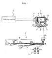
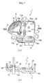
eine Schaltstellungserfassungseinrichtung (7) zum Erfassen einer Schaltstellung, die sich gemäß einer Betätigung einer Schaltvorrichtung durch einen Fahrzeugführer ändert, und eine Steuereinheit (5) mit einer Steuerplatine (10), die mehrere Vorrichtungen zum Steuern eines Getriebezuges basierend auf einem Erfassungssignal mindestens eines Fahrzeugfahrtzustandes aufweist, integriert und in einem Gehäuse (4) aufgenommen sind,
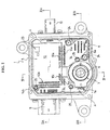
wobei die Schaltstellungserfassungseinrichtung (7) und die Steuereinheit (5) mit einer Verbindungsplatine (14) verbunden sind, und ein anderer Raum innerhalb des Gehäuses (4) als ein Raum, in dem die Steuerplatine (10) und die Schaltstellungserfassungseinrichtung (7) angeordnet sind, im Wesentlichen durch die Verbindungsplatine (14) besetzt ist, und
einen Verbinderabschnitt aufweist, der mit der Schaltstellungserfassungseinrichtung (7) und der Steuereinheit (5) integriert ist, und mit einer außerhalb des Gehäuses (4) angeordneten elektrischen Einheit verbindbar ist, wobei der Verbinderabschnitt über die Verbindungsplatine (14) mit der Steuerplatine (10) verbunden ist,
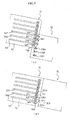
wobei der Verbinderabschnitt einen ersten Verbinder (8), der mit einer elektrischen Einheit innerhalb des Getriebezuges verbindbar ist, und einen zweiten Verbinder (9), der mit einem Fahrzeugsystem außerhalb des Getriebezuges verbindbar ist, aufweist, und
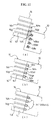
die Verbindungsplatine (14) eine erste Verbindungsplatine (14d) zum Verbinden der Schaltstellungserfassungseinrichtung (7) mit der Steuerplatine (10), eine zweite Verbindungsplatine (14e) zum Verbinden des zweiten Verbinders (9) mit der Steuerplatine (10) und eine dritte Verbindungsplatine zum Verbinden des ersten Verbinders (8) mit der Steuerplatine (10) aufweist, und
wobei von den ersten bis dritten Verbindungsplatinen zwei Verbindungsplatinen aus einer gemeinsamen Einzelplatine (14d) gebildet sind und die andere Verbindungsplatine (14e) von der gemeinsamen Einzelplatine getrennt ist. - Steuergerät mit Schaltstellungserfassungseinrichtung nach Anspruch 1, wobei die erste und die dritte Verbindungsplatine die gemeinsame Einzelplatine bilden, die von der zweiten Verbindungsplatine (14e) getrennt ist.
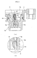
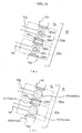
- Steuergerät mit Schaltstellungserfassungseinrichtung nach Anspruch 1 oder 2, wobei die Steuerplatine (10) in Form eines Rechtecks mit einer langen und einer kurzen Seite ausgebildet ist, und die Schaltstellungserfassungseinrichtung (7) und der erste Verbinder (8) in der Nähe der langen Seite angeordnet sind und der zweite Verbinder (9) in der Nähe der kurzen Seite.
- Steuergerät mit Schaltstellungserfassungseinrichtung nach Anspruch 3, wobei ein Verbindungsabschnitt des ersten Verbinders (8) und der Steuereinheit (5) eine Seite der Schaltstellungserfassungseinrichtung (7) überlappt.
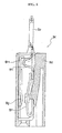
- Steuergerät mit Schaltstellungserfassungseinrichtung nach einem der Ansprüche 1 bis 4, wobei der Verbinderabschnitt, der mit einer elektrischen Einheit außerhalb des Gehäuses (4) verbindbar ist, einen Spannung absorbierenden und verringernden Abschnitt (8h1) aufweist.
- Getriebezug, dadurch gekennzeichnet, dass er das Steuergerät mit Schaltstellungserfassungseinheit nach einem der Ansprüche 1 bis 5 aufweist.
Priority Applications (1)
| Application Number | Priority Date | Filing Date | Title |
|---|---|---|---|
| EP10174343.3A EP2256374A3 (de) | 2002-03-27 | 2003-03-27 | Steuervorrichtung mit Schaltstellungsdetektor und Antriebsstrang mit der Steuervorrichtung |
Applications Claiming Priority (3)
| Application Number | Priority Date | Filing Date | Title |
|---|---|---|---|
| JP2002090011 | 2002-03-27 | ||
| JP2002090012 | 2002-03-27 | ||
| EP03715537A EP1489339B1 (de) | 2002-03-27 | 2003-03-27 | Steuervorrichtung mit schaltstellungsdetektor |
Related Parent Applications (1)
| Application Number | Title | Priority Date | Filing Date |
|---|---|---|---|
| EP03715537A Division EP1489339B1 (de) | 2002-03-27 | 2003-03-27 | Steuervorrichtung mit schaltstellungsdetektor |
Related Child Applications (1)
| Application Number | Title | Priority Date | Filing Date |
|---|---|---|---|
| EP10174343.3A Division-Into EP2256374A3 (de) | 2002-03-27 | 2003-03-27 | Steuervorrichtung mit Schaltstellungsdetektor und Antriebsstrang mit der Steuervorrichtung |
Publications (3)
| Publication Number | Publication Date |
|---|---|
| EP2006579A2 EP2006579A2 (de) | 2008-12-24 |
| EP2006579A3 EP2006579A3 (de) | 2009-10-14 |
| EP2006579B1 true EP2006579B1 (de) | 2014-12-17 |
Family
ID=28456311
Family Applications (4)
| Application Number | Title | Priority Date | Filing Date |
|---|---|---|---|
| EP08164879.2A Expired - Fee Related EP2006579B1 (de) | 2002-03-27 | 2003-03-27 | Steuervorrichtung mit Schaltstellungsdetektor und Antriebsstrang mit der Steuervorrichtung |
| EP10174343.3A Withdrawn EP2256374A3 (de) | 2002-03-27 | 2003-03-27 | Steuervorrichtung mit Schaltstellungsdetektor und Antriebsstrang mit der Steuervorrichtung |
| EP03715537A Expired - Fee Related EP1489339B1 (de) | 2002-03-27 | 2003-03-27 | Steuervorrichtung mit schaltstellungsdetektor |
| EP08165065A Withdrawn EP2017500A3 (de) | 2002-03-27 | 2003-03-27 | Steuervorrichtung mit Schaltstellungsdetektor und Antriebsstrang mit der Steuervorrichtung |
Family Applications After (3)
| Application Number | Title | Priority Date | Filing Date |
|---|---|---|---|
| EP10174343.3A Withdrawn EP2256374A3 (de) | 2002-03-27 | 2003-03-27 | Steuervorrichtung mit Schaltstellungsdetektor und Antriebsstrang mit der Steuervorrichtung |
| EP03715537A Expired - Fee Related EP1489339B1 (de) | 2002-03-27 | 2003-03-27 | Steuervorrichtung mit schaltstellungsdetektor |
| EP08165065A Withdrawn EP2017500A3 (de) | 2002-03-27 | 2003-03-27 | Steuervorrichtung mit Schaltstellungsdetektor und Antriebsstrang mit der Steuervorrichtung |
Country Status (8)
| Country | Link |
|---|---|
| US (1) | US7178419B2 (de) |
| EP (4) | EP2006579B1 (de) |
| JP (3) | JP4273325B2 (de) |
| KR (4) | KR20080048091A (de) |
| CN (1) | CN100425884C (de) |
| AU (1) | AU2003220823A1 (de) |
| DE (1) | DE60329908D1 (de) |
| WO (1) | WO2003081087A1 (de) |
Families Citing this family (25)
| Publication number | Priority date | Publication date | Assignee | Title |
|---|---|---|---|---|
| EP1789703B1 (de) * | 2004-09-16 | 2011-10-12 | Continental Automotive GmbH | Steuergerät für ein kraftfahrzeuggetriebe |
| DE102005020926B4 (de) * | 2005-05-04 | 2007-01-18 | Siemens Ag | Steuergerät für ein Kraftfahrzeuggetriebe |
| DE112006000371A5 (de) * | 2005-04-15 | 2007-11-22 | Conti Temic Microelectronic Gmbh | Steuergerät |
| CN100400936C (zh) * | 2006-05-29 | 2008-07-09 | 长沙航空工业中南传动机械厂 | 机械自动变速器换档执行机构 |
| US7539571B2 (en) * | 2006-06-05 | 2009-05-26 | Cnh America Llc | Non-contact neutral sensing with directional feedback |
| DE102006047187B3 (de) * | 2006-10-05 | 2008-04-10 | Siemens Ag | Steuervorrichtung |
| DE102007014354A1 (de) | 2007-03-26 | 2008-10-02 | Robert Bosch Gmbh | Steuergerät eines automatischen Getriebes mit einer Wählhebelstellungs-Detektoreinrichtung |
| DE102007032139A1 (de) | 2007-06-30 | 2009-01-02 | Robert Bosch Gmbh | Steuervorrichtung mit Positionssensor |
| KR100857076B1 (ko) * | 2007-08-08 | 2008-09-05 | 현대자동차주식회사 | 전자제어장치 |
| JP2009083573A (ja) * | 2007-09-28 | 2009-04-23 | Aisin Aw Co Ltd | 電気装置収納ユニット |
| CN101680538A (zh) * | 2007-09-28 | 2010-03-24 | 爱信艾达株式会社 | 自动变速器控制单元 |
| JP2009154564A (ja) * | 2007-12-25 | 2009-07-16 | Fujikura Ltd | レバーシャフトポジション検出装置 |
| US7767920B1 (en) * | 2009-03-04 | 2010-08-03 | Niles America Wintech, Inc. | Switch and welding method of same |
| FR2960378B1 (fr) * | 2010-05-21 | 2014-11-21 | Valeo Vision | Assemblage d'au moins deux cartes electriques |
| JP5459090B2 (ja) * | 2010-06-14 | 2014-04-02 | 株式会社デンソー | 自動変速機の制御装置 |
| DE102011088037A1 (de) * | 2011-12-08 | 2013-06-13 | Robert Bosch Gmbh | Anordnung eines Elektronikmoduls zwischen Getrieberaum und Motorraum |
| JP5863106B2 (ja) * | 2012-01-27 | 2016-02-16 | ミネベア株式会社 | モーター制御装置 |
| DE102012206783A1 (de) * | 2012-04-25 | 2013-10-31 | Zf Friedrichshafen Ag | Steuergerät, Zusatzsteuergerät sowie Steuersystem für ein Getriebe eines Fahrzeugs und Verfahren zum Zusammensetzen eines Steuersystems für ein Getriebe eines Fahrzeugs |
| CN104633077A (zh) * | 2013-11-12 | 2015-05-20 | 陕西国力信息技术有限公司 | 一种基于amt系统的选档主核控制cpu |
| CN104132808B (zh) * | 2014-07-15 | 2016-08-24 | 重庆山青机械制造有限公司 | 一种换挡换位组件检测装置 |
| EP3246601B1 (de) | 2015-01-14 | 2020-01-08 | Hitachi Automotive Systems, Ltd. | Elektronische steuerungsvorrichtung |
| CN106321819B (zh) * | 2015-06-25 | 2018-06-01 | 泰科电子(上海)有限公司 | 位置传感器及位置感测系统 |
| DE102015219571A1 (de) * | 2015-10-09 | 2017-04-13 | Conti Temic Microelectronic Gmbh | Sensordom-Anordnung |
| WO2019065423A1 (ja) * | 2017-09-29 | 2019-04-04 | アイシン・エィ・ダブリュ株式会社 | 車両用駆動装置 |
| CN108072342B (zh) * | 2017-11-23 | 2020-06-09 | 无锡合壮智慧交通有限公司 | 一种手动挡机动车档位的自动检测方法及装置 |
Citations (1)
| Publication number | Priority date | Publication date | Assignee | Title |
|---|---|---|---|---|
| EP1193423A2 (de) * | 2000-09-27 | 2002-04-03 | Aisin Aw Co., Ltd. | Automatisches Getriebe mit elektronischer Steuereinheit |
Family Cites Families (40)
| Publication number | Priority date | Publication date | Assignee | Title |
|---|---|---|---|---|
| JPS61159795A (ja) | 1984-12-29 | 1986-07-19 | マスプロ電工株式会社 | 電子機器 |
| US4790204A (en) * | 1987-07-16 | 1988-12-13 | Automotive Products, Plc | Electric shift apparatus |
| JPH023741A (ja) * | 1988-06-20 | 1990-01-09 | Jatco Corp | 電子制御式自動変速機 |
| US5042133A (en) * | 1989-03-15 | 1991-08-27 | Automotive Products (Usa) Inc. | Testing method for electric shift control apparatus |
| US5064975A (en) * | 1990-09-10 | 1991-11-12 | Caterpillar Inc. | Electrical transmission control mechanism |
| US5161422A (en) * | 1991-07-12 | 1992-11-10 | Prince Corporation | Universal control for electrically controlled vehicle transmission |
| US5101677A (en) | 1991-07-29 | 1992-04-07 | General Motors Corporation | Transmission mounted range selector |
| JPH0595175A (ja) | 1991-10-01 | 1993-04-16 | Mitsubishi Electric Corp | プリント基板の配線装置 |
| JPH0851019A (ja) | 1994-08-08 | 1996-02-20 | Nok Corp | 電装ユニット及びコネクタ |
| JPH08289505A (ja) * | 1995-04-17 | 1996-11-01 | Mitsubishi Electric Corp | 制御装置内蔵形電動機 |
| JP3601170B2 (ja) * | 1995-04-19 | 2004-12-15 | アイシン精機株式会社 | 車両の操舵制御装置 |
| DE19515622C2 (de) * | 1995-04-28 | 2000-06-08 | Telefunken Microelectron | Steuermodul von Kraftfahrzeugen |
| JPH08320064A (ja) * | 1995-05-25 | 1996-12-03 | Aisin Aw Co Ltd | 位置検出装置 |
| JPH0976785A (ja) * | 1995-09-18 | 1997-03-25 | Aisin Aw Co Ltd | 自動変速機の制御装置 |
| JP3802591B2 (ja) * | 1995-09-18 | 2006-07-26 | アイシン・エィ・ダブリュ株式会社 | 電子制御装置 |
| KR100433040B1 (ko) * | 1995-09-18 | 2004-08-09 | 아이신에이더블류 가부시키가이샤 | 위치검출장치 부착 전자제어장치 |
| US5847344A (en) * | 1996-07-08 | 1998-12-08 | Ford Global Technologies, Inc. | Position sensor for transmission gear selector switch |
| US5823071A (en) * | 1996-10-31 | 1998-10-20 | Borg-Warner Automotive, Inc. | Integrated transmission control system |
| KR19980036688A (ko) * | 1996-11-19 | 1998-08-05 | 모리 하루오 | 위치검출장치 |
| JP3478029B2 (ja) * | 1996-11-22 | 2003-12-10 | アイシン・エィ・ダブリュ株式会社 | 自動変速機用位置検出スイッチ一体型電子制御ユニット |
| KR100500522B1 (ko) * | 1996-11-22 | 2005-11-22 | 아이신에이더블류 가부시키가이샤 | 자동변속기용위치검출스위치일체형전자제어유닛 |
| EP0845620B1 (de) * | 1996-11-29 | 2007-01-10 | Aisin Aw Co., Ltd. | Wähleinrichtung mit elektronischer Steuereinheit für Automatikgetriebe |
| JP3470532B2 (ja) * | 1996-11-29 | 2003-11-25 | アイシン・エィ・ダブリュ株式会社 | ニュートラルスタートスイッチ一体型電子制御ユニット |
| JP3616980B2 (ja) * | 1997-04-22 | 2005-02-02 | ジヤトコ株式会社 | 自動変速機用制御ユニット |
| JPH10315797A (ja) * | 1997-05-15 | 1998-12-02 | Hitachi Ltd | 自動変速機用制御装置及び自動変速機 |
| JPH1131890A (ja) | 1997-07-10 | 1999-02-02 | Matsushita Electric Ind Co Ltd | 回路基板 |
| DE19745537B4 (de) * | 1997-10-15 | 2006-04-20 | Siemens Ag | Elektronisches Steuergerät zur Unterbringung in einem Kraftfahrzeug-Automatikgetriebe |
| JP3269449B2 (ja) * | 1998-02-24 | 2002-03-25 | 日産自動車株式会社 | バスバーインサート樹脂板 |
| JP2000052895A (ja) * | 1998-08-07 | 2000-02-22 | Anden | 車両用負荷制御装置 |
| US6144273A (en) * | 1998-08-31 | 2000-11-07 | Niles Parts Co., Ltd. | Inhibitor switch having magnetic contact portion |
| JP3248880B2 (ja) * | 1998-08-31 | 2002-01-21 | ナイルス部品株式会社 | インヒビタスイッチ |
| JP3456426B2 (ja) * | 1998-11-24 | 2003-10-14 | 住友電気工業株式会社 | 電子制御ユニット |
| JP3038656B1 (ja) * | 1998-12-16 | 2000-05-08 | ナイルス部品株式会社 | インヒビタスイッチ |
| JP3767844B2 (ja) * | 1999-04-30 | 2006-04-19 | 株式会社リコー | 機能拡張用制御装置 |
| KR100316883B1 (ko) * | 1999-05-10 | 2001-12-22 | 이계안 | 전자 공압식 변속장치의 변속 충격 저감 제어방법 |
| JP2001135202A (ja) * | 1999-10-29 | 2001-05-18 | Denso Corp | プリント基板の装着機構 |
| JP2001214773A (ja) | 2000-02-01 | 2001-08-10 | Toyota Motor Corp | 触媒保護装置 |
| JP2001214776A (ja) * | 2000-02-03 | 2001-08-10 | Hitachi Ltd | 自動車用制御装置 |
| JP3850199B2 (ja) * | 2000-03-10 | 2006-11-29 | ナイルス株式会社 | インヒビタスイッチ |
| JP3799270B2 (ja) * | 2001-12-21 | 2006-07-19 | 株式会社日立製作所 | 自動車の駆動状態を切り換える為の制御装置 |
-
2003
- 2003-03-27 EP EP08164879.2A patent/EP2006579B1/de not_active Expired - Fee Related
- 2003-03-27 EP EP10174343.3A patent/EP2256374A3/de not_active Withdrawn
- 2003-03-27 KR KR1020087011353A patent/KR20080048091A/ko not_active Application Discontinuation
- 2003-03-27 JP JP2003578785A patent/JP4273325B2/ja not_active Expired - Fee Related
- 2003-03-27 KR KR1020087027513A patent/KR100914373B1/ko not_active IP Right Cessation
- 2003-03-27 KR KR1020037016935A patent/KR100807492B1/ko active IP Right Grant
- 2003-03-27 EP EP03715537A patent/EP1489339B1/de not_active Expired - Fee Related
- 2003-03-27 CN CNB038010062A patent/CN100425884C/zh not_active Expired - Lifetime
- 2003-03-27 DE DE60329908T patent/DE60329908D1/de not_active Expired - Lifetime
- 2003-03-27 WO PCT/JP2003/003865 patent/WO2003081087A1/ja active Application Filing
- 2003-03-27 AU AU2003220823A patent/AU2003220823A1/en not_active Abandoned
- 2003-03-27 US US10/489,107 patent/US7178419B2/en not_active Expired - Lifetime
- 2003-03-27 EP EP08165065A patent/EP2017500A3/de not_active Withdrawn
- 2003-03-27 KR KR1020077028780A patent/KR20070122582A/ko not_active Application Discontinuation
-
2008
- 2008-12-26 JP JP2008332384A patent/JP4973884B2/ja not_active Expired - Fee Related
- 2008-12-26 JP JP2008332383A patent/JP4998751B2/ja not_active Expired - Lifetime
Patent Citations (1)
| Publication number | Priority date | Publication date | Assignee | Title |
|---|---|---|---|---|
| EP1193423A2 (de) * | 2000-09-27 | 2002-04-03 | Aisin Aw Co., Ltd. | Automatisches Getriebe mit elektronischer Steuereinheit |
Also Published As
| Publication number | Publication date |
|---|---|
| JP4998751B2 (ja) | 2012-08-15 |
| JP4273325B2 (ja) | 2009-06-03 |
| US7178419B2 (en) | 2007-02-20 |
| JP2009074698A (ja) | 2009-04-09 |
| KR20040108530A (ko) | 2004-12-24 |
| US20050028624A1 (en) | 2005-02-10 |
| KR20080106480A (ko) | 2008-12-05 |
| EP1489339B1 (de) | 2009-11-04 |
| EP1489339A1 (de) | 2004-12-22 |
| EP2017500A2 (de) | 2009-01-21 |
| EP2006579A3 (de) | 2009-10-14 |
| EP2017500A3 (de) | 2009-10-14 |
| EP2006579A2 (de) | 2008-12-24 |
| KR20080048091A (ko) | 2008-05-30 |
| EP1489339A4 (de) | 2006-08-09 |
| AU2003220823A1 (en) | 2003-10-08 |
| KR20070122582A (ko) | 2007-12-31 |
| JP2009074699A (ja) | 2009-04-09 |
| WO2003081087A1 (fr) | 2003-10-02 |
| EP2256374A3 (de) | 2014-01-08 |
| CN1554001A (zh) | 2004-12-08 |
| JPWO2003081087A1 (ja) | 2005-08-25 |
| CN100425884C (zh) | 2008-10-15 |
| KR100914373B1 (ko) | 2009-08-28 |
| DE60329908D1 (de) | 2009-12-17 |
| EP2256374A2 (de) | 2010-12-01 |
| JP4973884B2 (ja) | 2012-07-11 |
| KR100807492B1 (ko) | 2008-02-25 |
Similar Documents
| Publication | Publication Date | Title |
|---|---|---|
| EP2006579B1 (de) | Steuervorrichtung mit Schaltstellungsdetektor und Antriebsstrang mit der Steuervorrichtung | |
| US7621367B2 (en) | Electric power steering apparatus | |
| US7445081B2 (en) | Electric power steering apparatus | |
| US5311398A (en) | Housing for motor vehicle electronic system | |
| KR19990082019A (ko) | 차량용 제어 디바이스 | |
| JP2008516404A (ja) | フレキシブルな導体路におけるケーブルの接触接続 | |
| US6892699B2 (en) | Throttle body and air intake equipment for internal combustion engine | |
| US7080575B2 (en) | Mechatronic transmission control | |
| EP1403967A2 (de) | Verbindungsstruktur für eine Zusatzvorrichtung, Kabelwasserdichtungsstruktur für eine Zusatzvorrichtung und eine Montagestruktur für eine Zusatzvorrichtung | |
| CN113353145A (zh) | 电动助力转向装置和制造方法 | |
| JP3849477B2 (ja) | 自動変速機のコネクタシール装置 | |
| JP2001073829A (ja) | エンジン一体型制御装置、及びそれに用いられる回路体 | |
| JP2004314901A (ja) | 回転センサ付き回転コネクタ | |
| CN215870008U (zh) | 电子控制单元和车载压缩机 | |
| JP3470533B2 (ja) | ニュートラルスタートスイッチ一体型電子制御ユニット | |
| US20230148272A1 (en) | Rotating device | |
| JPH1041648A (ja) | 支持プレートにケーブルハーネスを固定するための装置 | |
| CN101216100B (zh) | 带换档位置检测装置的控制装置 | |
| JPS63302709A (ja) | 電子回路内臓型電気接続箱 | |
| JPH1169723A (ja) | 配線基板内蔵型モータ |
Legal Events
| Date | Code | Title | Description |
|---|---|---|---|
| PUAI | Public reference made under article 153(3) epc to a published international application that has entered the european phase |
Free format text: ORIGINAL CODE: 0009012 |
|
| AC | Divisional application: reference to earlier application |
Ref document number: 1489339 Country of ref document: EP Kind code of ref document: P |
|
| AK | Designated contracting states |
Kind code of ref document: A2 Designated state(s): DE FR GB |
|
| PUAL | Search report despatched |
Free format text: ORIGINAL CODE: 0009013 |
|
| AK | Designated contracting states |
Kind code of ref document: A3 Designated state(s): DE FR GB |
|
| 17P | Request for examination filed |
Effective date: 20091230 |
|
| 17Q | First examination report despatched |
Effective date: 20100202 |
|
| AKX | Designation fees paid |
Designated state(s): DE FR GB |
|
| GRAP | Despatch of communication of intention to grant a patent |
Free format text: ORIGINAL CODE: EPIDOSNIGR1 |
|
| INTG | Intention to grant announced |
Effective date: 20140528 |
|
| GRAS | Grant fee paid |
Free format text: ORIGINAL CODE: EPIDOSNIGR3 |
|
| RIN1 | Information on inventor provided before grant (corrected) |
Inventor name: FUKUDA, ATSUSHI Inventor name: TAKAMATSU, JUN Inventor name: OGASAWARA, NAOTO Inventor name: SUZUKI, KENJI Inventor name: MURAKAMI, NAOTAKA |
|
| RAP1 | Party data changed (applicant data changed or rights of an application transferred) |
Owner name: AISIN AW CO., LTD. |
|
| GRAA | (expected) grant |
Free format text: ORIGINAL CODE: 0009210 |
|
| AC | Divisional application: reference to earlier application |
Ref document number: 1489339 Country of ref document: EP Kind code of ref document: P |
|
| AK | Designated contracting states |
Kind code of ref document: B1 Designated state(s): DE FR GB |
|
| REG | Reference to a national code |
Ref country code: GB Ref legal event code: FG4D |
|
| REG | Reference to a national code |
Ref country code: DE Ref legal event code: R096 Ref document number: 60347123 Country of ref document: DE Effective date: 20150129 |
|
| REG | Reference to a national code |
Ref country code: DE Ref legal event code: R097 Ref document number: 60347123 Country of ref document: DE |
|
| PLBE | No opposition filed within time limit |
Free format text: ORIGINAL CODE: 0009261 |
|
| STAA | Information on the status of an ep patent application or granted ep patent |
Free format text: STATUS: NO OPPOSITION FILED WITHIN TIME LIMIT |
|
| 26N | No opposition filed |
Effective date: 20150918 |
|
| REG | Reference to a national code |
Ref country code: FR Ref legal event code: PLFP Year of fee payment: 14 |
|
| REG | Reference to a national code |
Ref country code: FR Ref legal event code: PLFP Year of fee payment: 15 |
|
| REG | Reference to a national code |
Ref country code: FR Ref legal event code: PLFP Year of fee payment: 16 |
|
| PGFP | Annual fee paid to national office [announced via postgrant information from national office to epo] |
Ref country code: DE Payment date: 20190312 Year of fee payment: 17 Ref country code: GB Payment date: 20190327 Year of fee payment: 17 |
|
| PGFP | Annual fee paid to national office [announced via postgrant information from national office to epo] |
Ref country code: FR Payment date: 20190213 Year of fee payment: 17 |
|
| REG | Reference to a national code |
Ref country code: DE Ref legal event code: R119 Ref document number: 60347123 Country of ref document: DE |
|
| PG25 | Lapsed in a contracting state [announced via postgrant information from national office to epo] |
Ref country code: DE Free format text: LAPSE BECAUSE OF NON-PAYMENT OF DUE FEES Effective date: 20201001 Ref country code: FR Free format text: LAPSE BECAUSE OF NON-PAYMENT OF DUE FEES Effective date: 20200331 |
|
| GBPC | Gb: european patent ceased through non-payment of renewal fee |
Effective date: 20200327 |
|
| PG25 | Lapsed in a contracting state [announced via postgrant information from national office to epo] |
Ref country code: GB Free format text: LAPSE BECAUSE OF NON-PAYMENT OF DUE FEES Effective date: 20200327 |