EP2004014B1 - Vorrichtung für die bewegungsbeeinflussung eines bewegbaren möbelteils und möbel mit einer solchen vorrichtung - Google Patents
Vorrichtung für die bewegungsbeeinflussung eines bewegbaren möbelteils und möbel mit einer solchen vorrichtung Download PDFInfo
- Publication number
- EP2004014B1 EP2004014B1 EP07723975.4A EP07723975A EP2004014B1 EP 2004014 B1 EP2004014 B1 EP 2004014B1 EP 07723975 A EP07723975 A EP 07723975A EP 2004014 B1 EP2004014 B1 EP 2004014B1
- Authority
- EP
- European Patent Office
- Prior art keywords
- furniture
- configuration mode
- control unit
- furniture part
- configuration
- Prior art date
- Legal status (The legal status is an assumption and is not a legal conclusion. Google has not performed a legal analysis and makes no representation as to the accuracy of the status listed.)
- Not-in-force
Links
Images
Classifications
-
- A—HUMAN NECESSITIES
- A47—FURNITURE; DOMESTIC ARTICLES OR APPLIANCES; COFFEE MILLS; SPICE MILLS; SUCTION CLEANERS IN GENERAL
- A47B—TABLES; DESKS; OFFICE FURNITURE; CABINETS; DRAWERS; GENERAL DETAILS OF FURNITURE
- A47B88/00—Drawers for tables, cabinets or like furniture; Guides for drawers
- A47B88/40—Sliding drawers; Slides or guides therefor
- A47B88/453—Actuated drawers
- A47B88/457—Actuated drawers operated by electrically-powered actuation means
-
- A—HUMAN NECESSITIES
- A47—FURNITURE; DOMESTIC ARTICLES OR APPLIANCES; COFFEE MILLS; SPICE MILLS; SUCTION CLEANERS IN GENERAL
- A47B—TABLES; DESKS; OFFICE FURNITURE; CABINETS; DRAWERS; GENERAL DETAILS OF FURNITURE
- A47B88/00—Drawers for tables, cabinets or like furniture; Guides for drawers
- A47B88/50—Safety devices or the like for drawers
- A47B88/53—Safety devices or the like for drawers preventing unintentional closing, e.g. anti-pinch devices
Definitions
- the invention relates to a device according to claims 1 to 12 or a furniture according to claim 13.
- Devices for influencing the movement of a plurality of furniture parts movable relative to a stationary furniture part are known from the prior art.
- the movable furniture parts are driven by means of a drive unit and a control unit for movement control of the movable furniture parts movable.
- movably guided or hinged to fittings furniture parts eg. As drawers, flaps, doors, folding doors and flaps, tray drawers, pharmacy cabinets and the like.
- furniture body mechanically or electrically supported z. B. be driven driven by an electric motor.
- the requirements increase with respect to individual wishes of the end user, for example, to allow a relatively high ease of use. In this case, the relevant effort for the manufacture, installation or commissioning of the device or the furniture should be kept relatively low.
- the US 6 109 774 A relates to a drawer operating system for dispensing goods from a locked storage.
- Object of the present invention is to provide a device for influencing the driven movement of movable furniture parts or equipped with such a device furniture, which requirements in terms of individual needs of the end user can be met and a necessary effort is minimized.
- the invention relates to a device for influencing the movement of a movable furniture part, which is driven by a drive unit via a control unit for controlling movement of the movable furniture part relative to a fixed furniture part movable.
- An essential aspect of the invention is that the control unit is operable in a working mode and in a configuration mode, wherein the control unit is designed to enter with additives in a configuration mode in which a configuration of the device can take place. In addition to a working mode, this makes it possible to provide a configuration mode selectively or comparatively easily. It can be easily accessed from the working mode in the configuration mode and vice versa.
- the activation means for activating and / or deactivating the configuration mode are switchable. In this way, the configuration mode can be defined via a switching process and set clearly recognizable or it can be left again.
- the control unit is designed with the additives which are formed as a separate additional component in the To enter configuration mode.
- a person can thus use a configuration mode particularly convenient. For example, it works well with a compact or handy additional component.
- inadvertent reconfiguration in particular can be virtually ruled out.
- the additional component is used in particular only for the configuration mode and can exercise influence on the control unit, for example, set an existing passive program to active or make a programming. Outside the configuration mode or in its deactivation state, the additional component represents in particular a passive element, which concerns the device for influencing the movement.
- the removable additional component may remain in the passive state in its mounting position or may be removed from the device or the Anbringplatz eg furniture.
- the separate additional component is designed as an attachment.
- the additional component of a person with a handle or easily attached to the device or be removed from this again. By attaching the necessary contacts or connections can be generated.
- a power supply for the Ansteckteil or the additional component via the plugging done. As a rule, the power supply via the power supply for the device for influencing the movement takes place.
- Configuration mode made possible or worked at any time by the user.
- basic settings for the operation of the device for influencing the movement or a piece of furniture equipped therewith can be defined.
- individual requirements or various settings can be made in the configuration mode, or they can be changed or undone again.
- the additives it is also ensured that an accidental or accidental adjustment of basic settings is almost impossible.
- the additives constitute, as it were, both a safety barrier and an access key for working in the configuration mode.
- the additives are different from a conventional PC or computer or a conventional arithmetic unit, whereby the additives are compared to significantly less expensive or less complex to provide.
- the additives include, for example, a portable small computer, laptop, PDA, USB stick or the like.
- the additives are provided in the control unit.
- the control unit form such that the control unit comprises the additive completely or partially.
- control unit can be understood to mean, for example, a control or computer unit, which in particular comprises a component for controlling the movement of a plurality of movable furniture parts and possibly responsible for all relevant movable furniture parts is or is controlled in each case.
- control unit can communicate with one another several times Having subunits, which are responsible for the movement control of the plurality of movable furniture parts, wherein a subunit controls at least one of the movable furniture parts.
- the additives may comprise, for example, a program stored in the control unit or be present as a structural unit in the control unit or the movement-influencing device.
- activation means for the activation and / or deactivation of the configuration mode which are permanently installed on the device and / or the relevant furniture parts, be provided.
- appropriate tripping commands may be necessary. Tripping orders can be executed in particular by a person from the outside.
- switchable operating or activating means provided via which a person can consciously activate a configuration mode or deactivate it to leave the configuration mode.
- the activation means a variety of configurations are conceivable, for example, as a separate or specially set up controls or as another function of a necessary for other purposes control.
- the activating means are provided by the movable furniture part, with its manual Movement by an operator of the configuration mode can be activated and / or deactivated.
- the configuration mode can be activated or deactivated particularly elegantly and with almost no additional effort compared to conventional arrangements.
- the activation of the configuration mode can be realized in a particularly simple manner by way of a specific or predefinable operation or an action on the movable furniture part.
- working in the activated configuration mode, in particular for setting target variables can also take place by acting on the relevant movable furniture part.
- the additional component may be at the control unit, especially if this is easily accessible, be attached directly or with this over appropriate connections, eg with lines or distribution elements with the control unit over a considerable distance in contact. So it is conceivable, for example, if a control unit, which is usually provided for a plurality of fixed furniture parts, is connected to these via at least one connecting line to connect the additional component to the connecting line or to a connection line connected to this indirectly. If appropriate, one or more distributor elements can be integrated in the connecting lines, for example one distributor element per stationary furniture part.
- the attachment to furniture sections for example, on walls, side, front parts or floor parts, also be provided in particular suitable connections to the movement-influencing device or the control unit.
- the additional component can also be used for other control units or a maintenance, repair or a change of the internal structure or a programming of the additional component is advantageously possible.
- the separate additional component has at least one operating element. This allows a switching operation to be performed directly on the additional component.
- the configuration mode can be switched on or off.
- one of several available different configuration modes can be selected or activated, if necessary. This can be done via exactly one control element or several control elements. If several control elements are present on the separate additional component, these can be used to execute other operating commands in the configuration mode or transmit them to the control unit.
- the configuration mode can be activated, deactivated or selected via other means.
- an operating element may be present on the furniture or the furniture parts, for example as a switch, sensor and the like.
- a control element in a broader sense comes as already explained, a movable furniture part in question, e.g. by this is moved or acted on, in particular by pressure and / or train.
- output means are provided to indicate to a person information about the configuration mode. Particularly in the configuration mode, it may be advantageous for a person executing the configuration mode if information about the configuration mode is displayed or feedback is provided with regard to configuration steps that have been carried out.
- the information may be such as to indicate to the person whether the configuration mode is active or not active, which configuration mode of several possible ones is currently active and / or which state currently prevails or has been reached in the current configuration mode. This can advantageously be done via output means of the additive or the separate additional component.
- the output means can be designed such that in particular acoustic, haptic and / or optical information can be transmitted to a person.
- control unit is designed to operate in a configuration mode of several possible configuration modes.
- configuration modes In modern systems, or when different objectives are to be achieved with the configuration, it is often advantageous if different configuration modes are available from which to select for a desired configuration.
- a configuration of a system can often be done by only one configuration mode, but there are also cases conceivable in which the configuration makes multiple selectable configuration modes necessary or the entire configuration includes several individual configurations in each case different configuration modes.
- the different configuration modes can be activated or selected in particular via the additives, for which purpose they can be equipped without or with at least one operating element.
- control unit is configured to operate in a configuration mode which is suitable for setting a closing part which is formed between a front part of the movable furniture part in the closed position with respect to the stationary furniture part.
- a front or closing gap is formed between the movable furniture part and the associated part in the closed state of the movable furniture part, which is preferably adjustable or variable.
- the control unit is designed accordingly, in particular in order to make an adjustment or adjustment of the closing gap in the configuration mode, which can be supported in particular by the drive unit and / or electrically.
- control unit is configured to operate in a configuration mode to allow assignment of the respective movable furniture parts to the associated stationary furniture part.
- control unit may be configured to operate in a configuration mode to allow for the allocation of adjacent stationary furniture parts in the presence of several fixed furniture parts.
- the additional component can be designed as a so-called "dongle".
- the dongle can have a copy or program protection function or have the function of an electrical key.
- at least one switching or operating element can be provided on the additional component or the dongle with which, in particular, the configuration mode can be switched on or off.
- the dongle can have a multi-level, in particular eg 3-level, switch or a control element.
- a reset function can be stored, for example, for a kitchen application to delete a kitchen configuration and return to the default setting.
- the kitchen or the device for influencing the movement of the kitchen area is set in configuration readiness.
- stage 2 for example, an electronic adjustment of a front gap of a movable furniture part respectively.
- further stages may be integrated in the switch or operating element, in particular for additional or later inflowing functions, for example for a child safety device.
- a basic setting can correspond to a factory setting, which in particular ensures emergency operation.
- a movable furniture part or power supply can be open and only this furniture part can be in motion.
- the configuration process can be performed by a person or a fitter.
- the dongle or the additional component with the switch or control element to "Level 1" is plugged into a slot, whereby the kitchen or the device for influencing the movement of the kitchen area is put into the configuration mode.
- the person or the fitter taps from bottom to top all movable furniture parts of stacked furniture parts. Thus, the furniture parts are extended and remain in the open state.
- the control unit knows which movable furniture part belongs to the same stationary furniture part. Thereafter, for each additional fixed furniture part, e.g. for all other carcasses a kitchen proceeded accordingly.
- a corresponding interior logic can be configured or can thus be avoided when collapsing an interior furniture part front collisions.
- a movable furniture part is opened, for example, to the maximum opening path or end stop and should open in the same body another movable furniture part be stopped this movable furniture part just before the opening path of the previously opened movable furniture part, for example, about 3 cm in front of it.
- the invention is also directed to a device for influencing the movement of a movable furniture part, which is driven by a drive unit via a control unit for movement control of the movable furniture part relative to a fixed furniture part movable.
- the control unit is designed to allow a movement influencing, after which the movement of the movable furniture parts is carried out immediately after one another within a corresponding stationary furniture part according to a predeterminable sequence.
- Such possibly cascaded movement of e.g. several open-standing movable furniture parts in a fixed furniture part may be advantageous to avoid collisions or injury to a person.
- a cascade-like opening profile within a fixed furniture part can proceed as follows: After all fixed furniture parts were configured in the above manner, a configuration for adjacent eg over-arranged furniture parts done by simultaneously tapping the two lowest movable furniture parts of the two over-positioned fixed furniture parts. As a result, the control unit recognizes adjacent, for example, over each other fixed furniture parts and does not allow simultaneous driving or be open of movable furniture parts of these two fixed furniture parts.
- adjacent stationary furniture parts can be proceeded accordingly, in particular to minimize a risk of collision or pinch by juxtaposed in each other fixed furniture parts at the same time moving furniture parts.
- the unconfigured movable furniture part remains open after deduction of the additional component or in case of incorrect configuration of a movable interior furniture part and the associated movable exterior furniture part. In this case, the partial configuration is discarded when subtracting the additional component.
- first movable furniture part or a power supply can move driven.
- Another or second movable furniture part may start about 10 to 70, especially 40 millimeters before closing the moving furniture part.
- a risk of crushing can be kept low.
- Movable furniture parts of two over-arranged or juxtaposed stationary furniture parts can not move at the same time.
- a movable furniture part may only be open or move with a stationary furniture part.
- the additional component may e.g. on a motor unit, e.g. an electric motor, be attached to the power supply or to the control unit of the device for influencing the movement.
- the additional component or the dongle can also be attached to a cabinet distributor on the furniture.
- acoustic information can be transmitted, which indicates to a person in a suitable manner, for example, a currently valid configuration mode. This can be done for example by a beep, which e.g. every 5 seconds.
- a "reset setting" can be made. This can be done for example via a switch or a control element on the additional component or the dongle.
- an operating action that does not occur in practice can also be specified, which must be carried out for this purpose.
- an operating element for example, serve one or more fronts of a movable furniture part. If a front or movable furniture part is e.g. ten times without waiting time in succession opened, thereby the configuration mode can be activated.
- the invention also relates to a piece of furniture with a fixed furniture part and at least one driven furniture part, in particular with a drawer.
- a piece of furniture with a fixed furniture part and at least one driven furniture part, in particular with a drawer.
- one of the devices described above is provided in the furniture.
- the resulting benefits for a corresponding furniture can be realized.
- the furniture with the device for influencing movement is designed in particular such that the additives are attachable to the furniture in the form of a separate additional component.
- the additional component for the configuration on the furniture can be attached to a corresponding attachment device, e.g. plugged in or connected and removed after configuration.
- the additional component can be affixed to the furniture at a favorable location or can be easily reached by a person, in particular via an interface of the control unit.
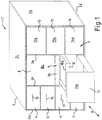
- FIG. 1 is a piece of furniture 1 with a fixed furniture part or a furniture body 2 and on this movably guided furniture drawers 3 with several drawers 4 to 14 shown.
- An outer drawer 11 can cover the front part 9a of an inner drawer 9 and the front part 10a of an inner drawer 10 with its front part 11a.
- the furniture 1 shows a cuboid shape.
- the furniture body 2 comprises two outer side walls 2a and 2b, an upper part 2c, a bottom part 2d and also an in FIG. 1 unrecognizable back wall.
- the furniture body 2 also has inside the furniture body parallel to the side walls 2a, 2b extending inner walls 2e and 2f.
- the furniture drawers 3 can be inserted or extended according to the double arrow P relative to the furniture body 2.
- the drawers 4 to 9 and 12 to 14 are each in the closed position, whereas the inner drawer 10 is approximately half or the outer drawer 11 is completely open relative to the furniture body 2.
- the front of the furniture 1 with front parts of the furniture drawers 3 represent an operating page for the operation of the drawers 4 to 14 by a person.
- the arrangement of the drawers with a view of the front of the furniture 1 according FIG. 1 includes three columns, each with several layers positioned drawers.
- the left column, seen from the front, comprises between the side wall 2b and the inner wall 2f the similar drawers 4 to 7 and the middle gaps between the inner walls 2e and 2f the drawers 8 to 11 and the right column between the inner wall 2e and the side wall 2a Drawers 12 to 14.
- each furniture push 4 to 14 relative to the furniture body 2 is a device, not shown, for example according to the in the WO 2006/029 894 A1 described device, provided for influencing the movement of the furniture drawers 3, wherein the driven movement takes place with a drive unit or a control unit for controlling movement of the furniture drawers 3. Also not shown are connecting lines or the like, for example for supplying the device for influencing the movement.
- the drawers 4 to 6 are provided at their drawer fronts each with a handle element 15 to 17 and the drawer 7 with an unrecognizable handle element to manually grab the drawer in question and in particular to pull on the drawer. Therefore, it is basically possible that the drawers 4 to 7 are not driven by the drive unit but only manually operated are movable. It is also conceivable that the drawers 4 to 7 are driven and manually movable, e.g. in their manually performed by a person movement to assist with the drive unit, especially when opening.
- the other drawers are movable in particular with the drive unit, and it is conceivable that a driven movable drawer can also be moved manually.
- the drive unit can be designed in many ways and work with electrical means, for example by means of an electric motor or not electrically by mechanical means or with a combination of these means function.
- the opening and / or closing movement can be wholly or partially driven, for example, when ejection means are provided for ejecting the movable furniture part from a closed position to an at least partially open position.
- the drawers 8 to 14 are provided at their front parts 8a to 14a without contour or without a handle element or other assistance for pulling on the respective furniture part.
- the drawers 4 to 14 may be with or without e.g. be provided in particular ejector or touch-latch functionality.
- the drawers 8 to 14 can be triggered, for example, by tapping on the front of a drawer or open or close.
- the additional component can be permanently integrated in the device for influencing the movement or even temporarily connected to it.
- the additional component can be attached to the device, for example, with a simple handle and removed again, e.g. by attaching or removing.
- the additional component can comprise a separate component, for example a small or mainframe computer, a laptop, a PDA, a network structure, a chip element or the like or integrated in the device or the control unit.
- input and / or output means may be present, e.g. a keypad or at least a switch.
- the additional component can also be designed as an electronic switch or as a so-called dongle, for example in the manner of an electronic key.
- the dongle can, for example, tell a bus master that the configuration is being carried out.
- an additional element or dongle can be delivered with, in particular to allow the general and in particular the closing gap configuration.
- the dongle can for example be plugged in at a free outlet of a horizontal wiring. This makes the configuration easy for laymen to perform.
- the dongle can in particular have a switch position "configuration" that can be selected by a person.
- the dongle only needs to be plugged into a slot, e.g. a drawer system are plugged.
- a short release tone sounds, the readiness of the dongle is reached.
- the system detection expires, which can take for example about 1 minute.
- the configuration process in the setting mode is only started after a continuously repeated signal tone.
- a reset to basic settings or a "reset" function can be done by resetting the dongle to emergency operation.
- a switch on the dongle can be set to emergency mode.
- the dongle is put on a free outlet on the furniture or the device for influencing the movement and a corresponding signal sounds for confirmation. Now one waits until a continuously repeated signal sounds and then the dongle can be removed. This procedure restores a basic setting.
- a front view can be set up, in which all relevant fronts of the movable furniture parts or drawers are flush with each other. For example, a corresponding drawer is tapped when the dongle is plugged in and the system or control unit is added to the dongle preset default setting or a touch-latch position an impulse. The drawer moves to a new touch latch position, which has a new front gap dimension.
- the configuration mode is terminated when the desired closing gap is reached, for example, by the expiration of a time specification by itself or by actuation of the switch on the additional component or of another operating element.
- FIG. 1 shows a furniture with several drawers.
- the invention also relates to other furniture with driven movable furniture parts such as doors, flaps, tray drawers, wire baskets, pharmacy cabinets, bogies, carousels or the like.
Landscapes
- Drawers Of Furniture (AREA)
- Power-Operated Mechanisms For Wings (AREA)
- Invalid Beds And Related Equipment (AREA)
- Two-Way Televisions, Distribution Of Moving Picture Or The Like (AREA)
- Specific Sealing Or Ventilating Devices For Doors And Windows (AREA)
Description
- Die Erfindung betrifft eine Vorrichtung nach den Ansprüchen 1 bis 12 bzw. ein Möbel nach Anspruch 13.
- Aus dem Stand der Technik sind Vorrichtungen für die Beeinflussung der Bewegung von mehreren gegenüber einem feststehenden Möbelteil bewegbaren Möbelteile bekannt. Die bewegbaren Möbelteile sind mit Hilfe einer Antriebseinheit und einer Kontrolleinheit zur Bewegungskontrolle der bewegbaren Möbelteile angetrieben bewegbar.
- Beispielsweise können verfahrbar geführte oder an Beschlägen verschwenkbare Möbelteile, z. B. Schubladen, Klappen, Türen, Falttüren bzw. -klappen, Tablarauszüge, Apothekenschränke und dgl. gegenüber einem Möbelkorpus mechanisch bzw. elektrisch unterstützt z. B. über einen Elektromotor angetrieben bewegt werden. Insbesondere bei modernen Anwendungen, steigen die Anforderungen im Hinblick auf individuelle Wünsche des Endnutzers, beispielsweise um einen relativ hohen Bedienkomfort zu ermöglichen. Dabei soll der diesbezügliche Aufwand für die Herstellung, Installation bzw. Inbetriebnahme der Vorrichtung bzw. des Möbels vergleichsweise gering gehalten werden.
- Die
US 6 109 774 A betrifft ein Schubladenbetätigungssystem zur Ausgabe von Gütern aus einer abgeschlossenen Aufbewahrung. - Aufgabe der vorliegenden Erfindung ist es, eine Vorrichtung für die Beeinflussung der angetriebenen Bewegung von bewegbaren Möbelteilen bzw. ein mit einer solchen Vorrichtung ausgestattetes Möbels bereitzustellen, wodurch Anforderungen im Hinblick auf individuelle Wünsche des Endnutzers erfüllbar sind und ein dafür notwendiger Aufwand minimiert ist.
- Diese Aufgabe wird durch die Ansprüche 1 und 13 gelöst. In den abhängigen Ansprüchen sind vorteilhafte Ausführungsformen der Erfindung aufgezeigt.
- Die Erfindung geht aus von einer Vorrichtung für die Bewegungsbeeinflussung eines bewegbaren Möbelteils, das mittels einer Antriebseinheit über eine Kontrolleinheit zur Bewegungskontrolle des bewegbaren Möbelteils relativ zu einem feststehenden Möbelteil angetrieben bewegbar ist. Ein wesentlicher Aspekt der Erfindung liegt darin, dass die Kontrolleinheit in einem Arbeitsmodus und in einem Konfiguriermodus betreibbar ist, wobei die Kontrolleinheit ausgebildet ist, mit Zusatzmittel in einen Konfiguriermodus zu gelangen, in welchem eine Konfigurierung der Vorrichtung erfolgen kann. Damit lässt sich neben einem Arbeitsmodus wahlweise bzw. vergleichsweise einfach ein Konfiguriermodus bereitstellen. Dabei kann ohne Weiteres aus dem Arbeitsmodus in den Konfiguriermodus und umgekehrt gelangt werden.
- Die Aktivierungsmittel zum Aktivieren und/oder Deaktivieren des Konfiguriermodus sind schaltbar. Auf diese Weise lässt sich über einen Schaltvorgang der Konfiguriermodus definiert und deutlich erkennbar einstellen bzw. kann dieser wieder verlassen werden.
- Die Kontrolleinheit ist ausgelegt, mit den Zusatzmitteln, die als eine separate Zusatzkomponente ausgebildet sind, in den Konfiguriermodus zu gelangen. Eine Person kann damit einen Konfiguriermodus besonders bequem nutzen. Beispielsweise lässt es sich mit einer kompakten bzw. handlichen Zusatzkomponente gut arbeiten. Darüber hinaus kann insbesondere ein versehentliches Umkonfigurieren nahezu ausgeschlossen werden. Die Zusatzkomponente wird insbesondere lediglich für den Konfiguriermodus verwendet und kann dabei Einfluss auf die Kontrolleinheit ausüben, z.B. ein vorhandenes passives Programm auf aktiv setzen bzw. eine Programmierung vornehmen. Außerhalb des Konfiguriermodus bzw. in dessen Deaktivierungszustand stellt die Zusatzkomponente insbesondere ein passives Element dar, was die Vorrichtung zur Bewegungsbeeinflussung angeht. Die entfernbare Zusatzkomponente kann im passiven Zustand in ihrer Anbringposition verbleiben oder kann von der Vorrichtung bzw. dem Anbringplatz z.B. am Möbel abgenommen werden.
- Die separate Zusatzkomponente ist als Ansteckteil ausgestaltet. Damit kann die Zusatzkomponente von einer Person mit einem Handgriff bzw. auf einfache Weise an der Vorrichtung angebracht bzw. von dieser wieder entfernt werden. Mit dem Aufstecken können auch die notwendigen Kontakte bzw. Verbindungen generiert werden. Falls nötig, z.B. wenn die Zusatzkomponente eine eigene Energiequelle benötigt und keine eigene Energiezuleitung bzw. batterie- oder akkugestützte Energieversorgung der Zusatzkomponente vorhanden ist, kann auch eine Energieversorgung für das Ansteckteil bzw. die Zusatzkomponente über das Anstecken erfolgen. In der Regel erfolgt die Energieversorgung über die Energieversorgung für die Vorrichtung zur Bewegungsbeeinflussung.
- Bisher wurde mit der Fertigstellung der Vorrichtung bzw. des damit ausgestatteten Möbels ab Werk eine insbesondere universelle Grundeinstellung zur Verfügung gestellt, die vom Endnutzer bzw. Laien nicht praktikabel veränderbar ist.
- Mit den vorgeschlagenen Zusatzmitteln kann der
- Konfiguriermodus möglich gemacht bzw. darin jederzeit vom Nutzer gearbeitet werden. Im Konfiguriermodus lassen sich insbesondere grundlegende Einstellungen für den Betrieb der Vorrichtung für die Bewegungsbeeinflussung bzw. ein damit ausgestattetes Möbel festlegen. Mit Hilfe der Zusatzmittel lassen sich im Konfiguriermodus individuelle Anforderungen bzw. unterschiedlichste Einstellungen vornehmen bzw. auch wieder ändern oder rückgängig machen. Mit den Zusatzmitteln ist es außerdem sichergestellt, dass ein ungewolltes bzw. versehentliches Verstellen von Grundeinstellungen nahezu ausgeschlossen ist. Die Zusatzmittel stellen sozusagen sowohl eine Sicherheitsbarriere als auch ein Zugangsschlüssel zum Arbeiten im Konfiguriermodus dar.
- Vorteilhafterweise sind die Zusatzmittel von einem herkömmlichen PC bzw. Computer bzw. einer herkömmlichen Recheneinheit verschieden, wodurch die Zusatzmittel im Vergleich dazu deutlich kostengünstiger bzw. weniger komplex bereitstellbar sind. Es ist aber auch denkbar, dass die Zusatzmittel zum Beispiel einen tragbaren Kleinrechner, Laptop, PDA, USB-Stick oder dergleichen umfassen.
- Bevorzugt sind die Zusatzmittel in der Kontrolleinheit bereitgestellt. Auf diese Weise lässt sich ohne dass eine weitere Einrichtung nötig ist bzw. mit wenig Aufwand die Kontrolleinheit derart ausbilden, dass die Kontrolleinheit die Zusatzmittel ganz oder teilweise umfasst.
- Unter dem Begriff der Kontrolleinheit kann im Sinne der Erfindung z.B. eine Regel- bzw. Steuereinheit verstanden werden, insbesondere eine Rechen- bzw. Computereinheit, die insbesondere ein Bauelement für die Bewegungskontrolle einer Mehrzahl von bewegbaren Möbelteilen umfasst und ggf. für alle betreffenden bewegbaren Möbelteile zuständig ist bzw. diese jeweils kontrolliert. Alternativ oder zusätzlich kann die Kontrolleinheit mehrere miteinander kommunizierende Teileinheiten aufweisen, die für die Bewegungskontrolle der mehreren bewegbaren Möbelteile verantwortlich sind, wobei eine Teileinheit zumindest eines der bewegbaren Möbelteile kontrolliert.
- Die Zusatzmittel können beispielsweise ein in der Kontrolleinheit hinterlegtes Programm umfassen oder als Baueinheit in der Kontrolleinheit bzw. der Bewegungsbeeinflussungs-Vorrichtung vorhanden sein.
- Weiter wird vorgeschlagen, dass fest an der Vorrichtung und/oder den betreffenden Möbelteilen installierte Aktivierungsmittel für die Aktivierung und/oder Deaktivierung des Konfiguriermodus vorhanden sind. Um insbesondere aus dem Arbeitsmodus, in welchem sich die Vorrichtung in der Regel befindet, in einen Konfiguriermodus zu gelangen bzw. diesen zu aktivieren, können entsprechende Auslösebefehle notwendig sein. Auslösebefehle können insbesondere von außen durch eine Person ausgeführt werden. Dazu sind z.B. schaltbare Bedien- bzw. Aktivierungsmittel vorgesehen, über welche eine Person bewusst einen Konfiguriermodus aktivieren bzw. zum Verlassen des Konfiguriermodus diesen deaktivieren kann. Als Aktivierungsmittel sind die unterschiedlichsten Ausgestaltungen denkbar, beispielsweise als separate bzw. eigens dafür eingerichtete Bedienelemente oder als weitere Funktion eines für andere Zwecke notwendigen Bedienelements.
- In einer vorteilhaften Ausführungsform des Erfindungsgegenstandes werden die Aktivierungsmittel durch das bewegbare Möbelteil bereitgestellt, mit dessen manueller Bewegung durch eine Bedienperson der Konfiguriermodus aktivierbar und/oder deaktivierbar ist. Auf diese Weise kann besonders elegant und nahezu ohne zusätzlichen Aufwand gegenüber herkömmlichen Anordnungen der Konfiguriermodus aktiviert bzw. deaktiviert werden. Dies ist zudem vorteilhaft, da ein Einwirken auf die bewegbaren Möbelteile zu deren Bedienung ohnehin für einen Benutzer einen gewohnten Vorgang darstellt. Über eine gezielte bzw. vorgebbare Bedienung bzw. ein Einwirken auf das bewegbare Möbelteil kann die Aktivierung des Konfiguriermodus besonders einfach realisiert werden. Gegebenenfalls kann auch das Arbeiten im aktivierten Konfiguriermodus, insbesondere zum Einstellen von Zielgrößen, durch das Einwirken auf das betreffende bewegbare Möbelteil erfolgen.
- Die Zusatzkomponente kann an der Kontrolleinheit, besonders wenn diese gut zugänglich ist, direkt angebracht werden oder mit dieser über entsprechende Verbindungen, z.B. mit Leitungen bzw. Verteilerelementen mit der Kontrolleinheit auch über einen merklichen Abstand in Kontakt stehen. So ist es beispielsweise denkbar, wenn eine Kontrolleinheit, die in der Regel für mehrere feststehende Möbelteile vorgesehen ist, mit diesen über zumindest eine Verbindungsleitung verbunden ist, die Zusatzkomponente an der Verbindungsleitung oder an einer mit dieser verbundenen Verbindungsleitung indirekt zu verbinden. In den Verbindungsleitungen kann ggf. ein oder können mehrere Verteilerelement(en) integriert sein, z.B. je ein Verteilerelement pro feststehendem Möbelteil.
- Erfolgt die Anbringung an Möbelabschnitten zum Beispiel an Wandungen, Seiten-, Frontteilen oder Bodenteilen, sind ebenfalls insbesondere geeignete Verbindungen zur Bewegungsbeeinflussungs-Vorrichtung bzw. zur Kontrolleinheit vorzusehen. Mit der Abnehmbarkeit der Zusatzkomponente lässt sich die Zusatzkomponente auch für andere Kontrolleinheiten nutzen bzw. ist eine Wartung, Reparatur oder eine Veränderung der inneren Struktur bzw. eine Programmierung der Zusatzkomponente vorteilhaft möglich.
- In einer bevorzugten Ausführungsform des Erfindungsgegenstandes weist die separate Zusatzkomponente zumindest ein Bedienelement auf. Damit lässt sich direkt an der Zusatzkomponente ein Schaltvorgang ausführen. Insbesondere kann damit der Konfiguriermodus ein- bzw. ausgeschaltet werden. Außerdem kann damit ggf. einer von mehreren zur Verfügung stehenden unterschiedlichen Konfiguriermodi ausgewählt bzw. aktiviert werden. Dies kann über genau ein Bedienelement oder über mehrere Bedienelemente erfolgen. Wenn mehrere Bedienelemente an der separaten Zusatzkomponente vorhanden sind, können mit diesen im Konfiguriermodus sonstige Bedienbefehle ausgeführt bzw. an die Kontrolleinheit übermittelt werden.
- Es ist aber auch eine Ausgestaltung der Zusatzkomponente möglich, bei der diese keine Schalt- bzw. Bedienelemente aufweist. Dann kann über andere Mittel der Konfiguriermodus aktiviert, deaktiviert bzw. ausgewählt werden. Beispielsweise kann ein Bedienelement an dem Möbel bzw. den Möbelteilen vorhanden sein, zum Beispiel als Schalter, Sensor und dergleichen. Als Bedienelement im weiteren Sinne kommt wie bereits erläutert auch ein bewegbares Möbelteil in Frage, z.B. indem dieses bewegt bzw. darauf eingewirkt wird, insbesondere durch Druck und/oder Zug.
- Vorteilhafterweise sind Ausgabemittel vorhanden, um einer Person Informationen über den Konfiguriermodus anzuzeigen. Insbesondere im Konfiguriermodus kann es für eine den Konfiguriermodus ausführende Person von Vorteil sein, wenn Informationen über den Konfiguriermodus angezeigt werden bzw. eine Rückkopplung bezüglich getätigten Konfigurierschritten erfolgt. Die Information kann derart sein, dass der Person angezeigt wird, ob der Konfiguriermodus aktiv bzw. nicht aktiv ist, welcher Konfiguriermodus von mehreren mögliche gerade aktiv ist und/oder welcher Zustand gerade im aktuellen Konfiguriermodus herrscht bzw. erreicht ist. Dies kann vorteilhafterweise über Ausgabemittel der Zusatzmittel bzw. der separaten Zusatzkomponente geschehen. Die Ausgabemittel können derart ausgestaltet sein, dass insbesondere akustische, haptische und/oder optische Informationen an eine Person übermittelt werden können.
- Weiter wird vorgeschlagen, dass die Kontrolleinheit ausgebildet ist, in einem Konfiguriermodus von mehreren möglichen Konfiguriermodi zu arbeiten. Bei modernen Systemen bzw. wenn unterschiedliche Ziele mit der Konfigurierung erreicht werden sollen, ist es häufig vorteilhaft, wenn unterschiedliche Konfiguriermodi zur Verfügung stehen, aus denen für eine gewünscht Konfigurierung ausgewählt werden kann. Denn eine Konfigurierung eines Systems kann zwar häufig durch nur einen Konfiguriermodus erledigt werden, es sind aber auch Fälle denkbar, in denen die Konfigurierung mehrere wählbare Konfiguriermodi notwendig macht bzw. die gesamte Konfigurierung mehrere einzelne Konfigurierungen in jeweils unterschiedlichen Konfiguriermodi umfasst.
- Die unterschiedlichen Konfiguriermodi sind insbesondere über die Zusatzmittel aktivierbar bzw. auswählbar, wofür diese ohne oder mit zumindest einem Bedienelement ausgestattet sein können.
- Vorteilhafterweise ist die Kontrolleinheit ausgestaltet, in einem Konfiguriermodus zu arbeiten, der zum Einstellen eines Schließteils geeignet ist, der zwischen einer Frontpartie des bewegbaren Möbelteils in Schließposition gegenüber dem feststehenden Möbelteil ausgebildet ist. Häufig wird zwischen dem bewegbaren Möbelteil und dem dazugehörigen Teil im Schließzustand des bewegbaren Möbelteils ein Front- bzw. Schließspalt ausgebildet, der bevorzugt einstellbar bzw. veränderbar ist. Dies kann beispielsweise bei so genannten Touch-Latch-Anordnungen vorteilhaft bzw. notwendig sein. Hierfür ist die Kontrolleinheit entsprechend ausgestaltet, insbesondere um im Konfiguriermodus eine Verstellung bzw. eine Einstellung des Schließspalts vornehmen zu können, was insbesondere von der Antriebseinheit und/oder elektrisch unterstützt werden kann.
- Vorteilhafterweise ist die Kontrolleinheit ausgestaltet, in einem Konfiguriermodus zu arbeiten, um eine Zuordnung der betreffenden bewegbaren Möbelteile zu dem dazugehörigen feststehenden Möbelteils zu ermöglichen.
- Außerdem kann die Kontrolleinheit ausgestaltet sein, in einem Konfiguriermodus zu arbeiten, um bei Vorhandensein von mehreren feststehenden Möbelteilen, eine Zuordnung von benachbarten feststehenden Möbelteilen zu ermöglichen.
- Insbesondere kann die Zusatzkomponente als so genanntes "Dongle" ausgebildet sein. Das Dongle kann eine Kopier- bzw. Programmierschutzfunktion aufweisen bzw. die Funktion eines elektrischen Schlüssels besitzen. An der Zusatzkomponente bzw. dem Dongle kann insbesondere zumindest ein Schalt- bzw. Bedienelement vorgesehen sein, mit dem insbesondere der Konfiguriermodus ein- bzw. ausgeschaltet werden kann.
- Beispielsweise kann das Dongle über einen mehrstufigen, insbesondere z.B. 3-stufigen Schalter bzw. ein Bedienelement verfügen. In einer ersten Stellung bzw. "Stufe 0" kann beispielsweise eine Reset-Funktion hinterlegt sein, um z.B. für eine Küchen-Anwendung eine Küchenkonfiguration zu löschen und in die Grundeinstellung zurück zu gelangen. In einer zweiten Stellung bzw. "Stufe 1" wird die Küche bzw. die Vorrichtung zur Bewegungsbeeinflussung für den Küchenbereich in Konfigurationsbereitschaft gesetzt. In einer dritten Stellung bzw. "Stufe 2" kann z.B. eine elektronische Einstellung eines Frontspalts eines bewegbaren Möbelteils erfolgen. Gegebenenfalls können noch weitere Stufen im Schalter bzw. Bedienelement integriert sein, insbesondere für zusätzliche bzw. später einfließende Funktionen z.B. für eine Kindersicherung.
- Eine Grundeinstellung kann einer Werkseinstellung entsprechen, die insbesondere einen Notbetrieb gewährleistet. Zum Beispiel kann nur ein bewegbares Möbelteil bzw. Netzteil offen sein und nur dieses Möbelteil kann in Bewegung sein.
- Der Konfiguriervorgang kann von einer Person bzw. einem Monteur vorgenommen werden. Das Dongle bzw. die Zusatzkomponente mit dem Schalter bzw. Bedienelement auf "Stufe 1" wird an einem Steckplatz aufgesteckt, wodurch die Küche bzw. die Vorrichtung zur Bewegungsbeeinflussung für den Küchenbereich in den Konfiguriermodus versetzt wird. Die Person bzw. der Monteur tippt von unten nach oben alle bewegbaren Möbelteile von übereinander angeordneten Möbelteilen an. Damit werden die Möbelteile ausgefahren und bleiben in geöffnetem Zustand stehen. Durch nochmaliges Antippen des ersten bzw. untersten Möbelteils wird das feststehende Möbelteil abgeschlossen und die bewegbaren Möbelteile schließen automatisch von oben nach unten. Dadurch weiß die Kontrolleinheit, welches bewegbare Möbelteil zum selben feststehenden Möbelteil gehört. Danach wird für jedes weitere feststehende Möbelteile z.B. für alle weiteren Korpusse einer Küche entsprechend vorgegangen.
- Werden einem bewegbaren Außen-Möbelteil zugehörige Innen-Möbelteile zugeordnet, kann eine entsprechende Innenlogik konfiguriert bzw. können damit Frontkollisionen bei Absenkung eines Innen-Möbelteils vermieden werden.
- Wird ein bewegbares Möbelteil geöffnet, beispielsweise auf den maximalen Öffnungsweg bzw. Endanschlag und soll im gleichen Korpus ein weiteres bewegbares Möbelteil geöffnet werden, stoppt dieses bewegbare Möbelteil kurz vor dem Öffnungsweg des vorher geöffneten bewegbaren Möbelteils, zum Beispiel ca. 3 cm davor. Damit stoppt innerhalb eines Korpus jedes bewegbare Möbelteil kurz vor dem Öffnungsweg des bereits geöffneten bewegbaren Möbelteils, z.B. ca. 3 cm davor. Wenn ein bewegbares Möbelteil geschlossen werden soll, schließen vorher automatisch alle weniger weit geöffneten bewegbaren Möbelteile, bevor das betätigte bewegbare Möbelteil selbst schließt. Durch dieses kaskadenartige Bewegungsprofil innerhalb eines feststehenden Möbelteils wird keine Logik für bewegbare Innen-Möbelteile notwendig und auch eine Kollisionsgefahr zwischen über- oder untereinander liegenden bewegbare Möbelteile ist eliminiert.
- Die Erfindung ist zudem auf eine Vorrichtung zur Bewegungsbeeinflussung eines bewegbaren Möbelteils gerichtet, das mittels einer Antriebseinheit über eine Kontrolleinheit zur Bewegungskontrolle-des bewegbaren Möbelteils relativ zu einem feststehenden Möbelteil angetrieben bewegbar ist. Ein wesentlicher Aspekt ist dabei, dass die Kontrolleinheit ausgestaltet ist, eine Bewegungsbeeinflussung zu ermöglichen, wonach die Bewegung der bewegbaren Möbelteile innerhalb eines dazugehörigen feststehenden Möbelteils nach einem vorgebbaren Ablauf unmittelbar nacheinander ausgeführt wird. Eine solche ggf. kaskadenartig ablaufende Bewegung von z.B. mehreren offen stehenden bewegbaren Möbelteilen in einem feststehenden Möbelteil kann zur Vermeidung von Kollisionen oder Verletzungen einer Person vorteilhaft sein.
- Für ein kaskadenartiges Öffnungsprofil innerhalb eines feststehenden Möbelteils kann folgendermaßen vorgegangen werden: Nachdem alle feststehenden Möbelteile in der oben genannten Weise konfiguriert wurden, erfolgt eine Konfiguration für benachbarte z.B. übereck angeordnete Möbelteile durch gleichzeitiges Antippen der beiden untersten bewegbaren Möbelteile der beiden übereck positionierten feststehenden Möbelteile. Dadurch erkennt die Kontrolleinheit benachbarte z.B. übereck zueinander feststehende Möbelteile und erlaubt kein gleichzeitiges Fahren bzw. offen stehen von bewegbaren Möbelteilen aus diesen beiden feststehenden Möbelteilen.
- Auch für nebeneinander stehende feststehende Möbelteile kann entsprechend vorgegangen werden, um insbesondere eine Kollisions- bzw. Einklemmgefahr durch nebeneinander in jeweils anderen feststehenden Möbelteilen sich gleichzeitig bewegenden Möbelteile zu minimieren.
- Wenn ein bewegbares Möbelteil von einem ersten der beiden feststehenden Möbelteile geöffnet ist oder fährt, können gleichzeitig keine bewegbaren Möbelteile des zweiten feststehenden Möbelteils geöffnet werden. Die Konfiguration für übereck bzw. nebeneinander feststehende Möbelteile wird erst angenommen, wenn die Gesamt-Konfiguration an sich abgeschlossen wird bzw. wenn für alle anderen bewegbaren Möbelteile, die nicht z.B. übereck bzw. nebeneinander angeordnet sind, durch Antippen die Konfiguration abgeschlossen wurde.
- Falls die Konfiguration unvollständig ist bzw. beim Vorgehen durch Antippen die Betätigung eines bewegbaren Möbelteils vergessen wurde, bleibt das nicht konfigurierte bewegbare Möbelteil nach Abzug der Zusatzkomponente offen bzw. bei fehlerhafter Konfiguration eines bewegbaren Innen-Möbelteils auch das zugehörige bewegbare Außen-Möbelteil geöffnet. In diesem Falle wird beim Abziehen der Zusatzkomponente die unvollständige Konfiguration wieder verworfen.
- Für einen Betrieb nach der Konfiguration kann gelten:
Immer nur ein erstes bewegbares Möbelteil bzw. ein Netzteil kann sich angetrieben bewegen. Ein weiteres bzw. zweites bewegbares Möbelteil darf ca. 10 bis 70, insbesondere 40 Millimeter vor Schließung des zufahrenden Möbelteils starten. Damit kann eine Quetschgefahr gering gehalten werden. - Es können insbesondere mehrere bewegbare Möbelteile gleichzeitig offen sein.
- Es wird ein kaskadenartiges Öffnungsprofil innerhalb eines feststehenden Möbelteils zur Vermeidung von Frontkollisionen zwischen über- oder untereinander angeordneten Laden vorgegeben.
- Bewegbare Möbelteile zweier übereck bzw. nebeneinander angeordneten feststehenden Möbelteilen können sich nicht gleichzeitig bewegen. Insbesondere darf nur bei einem feststehenden Möbelteil ein bewegbares Möbelteil geöffnet sein bzw. sich bewegen.
- Die Zusatzkomponente kann z.B. an einer Motoreinheit, z.B. einem Elektromotor, am Netzteil oder an der Kontrolleinheit der Vorrichtung für die Bewegungsbeeinflussung angebracht werden. Die Zusatzkomponente bzw. das Dongle kann auch an einem Korpusverteiler am Möbel angebracht werden.
- Über die Zusatzkomponente bzw. das Dongle ist eine z.B. akustische Information übermittelbar, die einer Person im geeigneter Weise beispielsweise einen aktuell gültigen Konfiguriermodus anzeigt. Dies kann beispielsweise durch einen Piepston geschehen, welcher z.B. alle 5 Sekunden ertönt.
- Insbesondere in einem eigenen Konfiguriermodus kann eine "Reset-Einstellung" vorgenommen werden. Dies kann beispielsweise über einen Schalter bzw. ein Bedienelement an der Zusatzkomponente bzw. dem Dongle erfolgen.
- Um in den Konfiguriermodus zu gelangen, kann auch eine in der Praxis nicht vorkommende Bedienaktion vorgegeben werden, die dafür ausgeführt werden muss. Als Bedienelement kann beispielsweise eine oder mehrere Fronten eines bewegbaren Möbelteils dienen. Wird eine Front bzw. ein bewegbares Möbelteil z.B. zehnmal ohne Wartezeit hintereinander geöffnet, kann dadurch der Konfiguriermodus aktivieret werden.
- Des Weiteren kann eine Schließspalt- bzw. FrontspaltEinstellung mit den Zusatzmitteln bzw. der separaten Zusatzkomponente beispielsweise auf elektronische Weise erfolgen.
- Die Erfindung betrifft außerdem ein Möbel mit einem feststehenden Möbelteil und wenigstens einem angetrieben bewegbaren Möbelteil, insbesondere mit einer Schublade. Vorteilhafterweise ist bei dem Möbel eine der oben beschriebenen Vorrichtungen vorgesehen. Damit lassen sich die daraus resultierenden Vorteile für ein entsprechendes Möbel realisieren.
- Das Möbel mit der Vorrichtung zur Bewegungsbeeinflussung ist insbesondere derart ausgestaltet, dass die Zusatzmittel in Form einer separaten Zusatzkomponente am Möbel anbringbar sind. Beispielsweise kann die Zusatzkomponente für die Konfigurierung am Möbel an einer entsprechenden Anbringeinrichtung z.B. aufgesteckt bzw. verbunden und nach der Konfigurierung wieder entfernt werden. Insbesondere ist die Zusatzkomponente an einer günstigen bzw. für eine Person gut erreichbaren Stelle am Möbel anbringbar, insbesondere über eine Schnittstelle der Kontrolleinheit.
- Ein stark schematisch dargestelltes Ausführungsbeispiel der Erfindung ist in der einzigen Figur dargestellt und unter Angabe weiterer Vorteile und Details näher beschrieben.
- Figur 1
- zeigt ein schematisiertes Möbel in perspektivischer Frontansicht schräg von oben.
- In
Figur 1 ist ein Möbel 1 mit einem feststehenden Möbelteil bzw. einem Möbelkorpus 2 und an diesem bewegbar geführte Möbelschübe 3 mit mehreren Schubladen 4 bis 14 gezeigt. Eine Außenschublade 11 kann mit ihrer Frontpartie 11a die Frontpartie 9a einer Innenschublade 9 und die Frontpartie 10a einer Innenschublade 10 überdecken. Im geschlossenen Zustand der Möbelschübe 3 zeigt das Möbel 1 eine quaderförmig Gestalt. Der Möbelkorpus 2 umfasst zwei äußere Seitenwände 2a bzw. 2b, ein Oberteil 2c, ein Bodenteil 2d und außerdem eine inFigur 1 nicht erkennbare Rückwand. Der Möbelkorpus 2 verfügt außerdem über im Inneren des Möbelkorpus parallel zu den Seitenwänden 2a, 2b verlaufende Innenwände 2e und 2f. - Im Möbelkorpus 2 sind über nicht dargestellte Auszugsführungen die Möbelschübe 3 an den Seitenwänden 2a, 2b bzw. den Innenwänden 2e, 2f verfahrbar aufgenommen, zum Beispiel über bekannte Vollauszüge. Die Möbelschübe 3 können gemäß dem Doppelpfeil P relativ zum Möbelkorpus 2 eingeschoben bzw. ausgefahren werden. Die Schubladen 4 bis 9 und 12 bis 14 befinden sich jeweils in Schließposition, wohingegen die Innenschublade 10 in etwa halb bzw. die Außenschublade 11 ganz geöffnet gegenüber dem Möbelkorpus 2 ist.
- Die Vorderseite des Möbels 1 mit Frontpartien der Möbelschübe 3 stellen eine Bedienseite für die Bedienung der Schubladen 4 bis 14 durch eine Person dar. Die Anordnung der Schubladen mit Blick vorne auf das Möbel 1 gemäß
Figur 1 umfasst drei Spalten mit jeweils mehreren übereinander positionierten Schubladen. Die von vorne gesehen linke Spalte umfasst zwischen der Seitenwand 2b und der Innenwand 2f die gleichartigen Schubladen 4 bis 7 bzw. die mittlere Spalte zwischen den Innenwänden 2e und 2f die Schubladen 8 bis 11 und die rechte Spalte zwischen der Innenwand 2e und der Seitenwand 2a die Schubladen 12 bis 14. - Zur angetriebenen Bewegung insbesondere jedes Möbelschubs 4 bis 14 relativ zum Möbelkorpus 2 ist eine nicht dargestellte Vorrichtung, z.B. entsprechend der in der
WO 2006/029 894 A1 beschriebenen Vorrichtung, zur Bewegungsbeeinflussung der Möbelschübe 3 vorgesehen, wobei die angetriebenen Bewegung mit einer Antriebseinheit bzw. einer Kontrolleinheit zur Bewegungskontrolle der Möbelschübe 3 erfolgt. Ebenfalls nicht dargestellt sind Verbindungsleitungen oder dergleichen z.B. zur Versorgung der Vorrichtung zur Bewegungsbeeinflussung. - Die Schubladen 4 bis 6 sind an ihren Schubladenfronten jeweils mit einem Griffelement 15 bis 17 bzw. die Schublade 7 mit einem nicht erkennbaren Griffelement versehen, um die betreffende Schublade manuell zu greifen und insbesondere an der Schublade zu ziehen. Daher ist es grundsätzlich möglich, dass die Schubladen 4 bis 7 nicht mit der Antriebseinheit angetrieben sondern lediglich manuell betätigt bewegbar sind. Es ist auch denkbar, dass die Schubladen 4 bis 7 angetrieben und manuell bewegbar sind, um z.B. bei deren manuell von einer Person ausgeführten Bewegung diese mit der Antriebseinheit zu unterstützen, insbesondere beim Öffnen.
- Die anderen Schubladen sind insbesondere mit der Antriebseinheit bewegbar, wobei es denkbar ist, dass eine angetrieben bewegbare Schublade auch manuell bewegt werden kann. Die Antriebseinheit kann vielfältig ausgestaltet sein und mit elektrischen Mitteln z.B. mit Hilfe eines Elektromotors oder nicht elektrisch mit mechanischen Mitteln arbeiten bzw. mit einer Kombination aus diesen Mitteln funktionieren. Die Öffnungs- und/oder Schließbewegung kann ganz oder teilweise angetrieben erfolgen, z.B. wenn Ausstoßmittel zum Ausstoßen des bewegbaren Möbelteils aus einer Schließstellung in eine zumindest teilweise geöffnete Stellung vorgesehen sind.
- Die Schubladen 8 bis 14 sind an ihren Frontpartien 8a bis 14a ohne Kontur bzw. ohne ein Griffelement oder eine sonstige Hilfe zum Ziehen an dem betreffenden Möbelteil ausgestattet. Die Schubladen 4 bis 14 können mit oder ohne z.B. insbesondere Ausstoßer- bzw. Touch-Latch-Funktionalität versehen sein. Die Schubladen 8 bis 14 lassen sich zum Beispiel durch Antippen auf die Frontseite einer Schublade auslösen bzw. öffnen oder schließen.
- Als Zusatzkomponente sind unterschiedliche Ausgestaltungen denkbar. Die Zusatzkomponente kann dauerhaft in der Vorrichtung zur Bewegungsbeeinflussung integriert sein oder auch nur zeitweise mit dieser in Verbindung stehen. Die Zusatzkomponente kann beispielsweise mit einem einfachen Handgriff an der Vorrichtung angebracht und wieder entfernt werden, z.B. durch Aufstecken bzw. Abziehen. Die Zusatzkomponente kann ein separates Bauteil umfassen, bspw. einen Klein- oder Großrechner, ein Laptop, ein PDA, eine Netzwerkstruktur, ein Chipelement oder ähnliches oder integriert in der Vorrichtung bzw. der Kontrolleinheit vorhanden sein. Am Zusatzelement können Eingabe- und/oder Ausgabemittel vorhanden sein, z.B. ein Tastenfeld oder zumindest ein Schalter.
- Die Zusatzkomponente kann auch als elektronischer Schalter bzw. als so genanntes Dongle ausgeführt sein, beispielsweise in der Art eines elektronischen Schlüssels. Das Dongle kann z.B. einem Busmaster mitteilen, dass die Konfiguration durchgeführt wird. Für jede Möbeleinheit bzw. für eine ausgelieferte Gruppe von Möbel z.B. für eine Küche mit entsprechenden Küchenmöbel, kann ein Zusatzelement bzw. Dongle mit ausgeliefert werden, um insbesondere die allgemeine und insbesondere auch die Schließspalt-Konfiguration zu ermöglichen. Das Dongle kann beispielsweise an einem freien Abgang einer horizontalen Verkabelung eingesteckt werden. Damit lässt sich die Konfiguration auch für Laien problemlos durchführen.
- Zur Vorbereitung der Konfiguration kann das Dongle insbesondere eine Schalterstellung "Konfiguration" aufweisen, die von einer Person angewählt werden kann. Hierzu muss das Dongle lediglich auf einen Steckplatz z.B. eines Schubladensystems aufgesteckt werden. Nach Abwarten bis ein kurzer Freigabeton ertönt, ist die Bereitschaft des Dongles erreicht. Dann läuft die Systemerkennung ab, welche beispielsweise ca. 1 Minute dauern kann. Der Konfigurationsvorgang im Einstellmodus wird erst nach einem stetig sich wiederholenden Signalton gestartet.
- Eine Rückstellung auf Grundeinstellungen bzw. eine "Reset"-Funktion kann durch Zurücksetzen des Dongles auf Notbetrieb erfolgen. Alternativ kann ein Schalter am Dongle auf Notbetrieb gestellt werden. Hierzu wird das Dongle auf einen freien Abgang am Möbel bzw. der Vorrichtung zur Bewegungsbeeinflussung gesteckt und ein entsprechendes Signal zur Bestätigung ertönt. Nun wartet man, bis ein stetig wiederholendes Signal ertönt und danach kann das Dongle entfernt werden. Mit diesem Vorgehen wird eine Grundeinstellung wieder hergestellt.
- Zur optionalen Frontspalteinstellung mit dem Dongle kann eine Frontansicht eingerichtet werden, bei der alle betreffenden Fronten der bewegbaren Möbelteile bzw. Schubladen gleich bzw. fluchtend zueinander stehen. Zum Beispiel wird eine entsprechende Schublade bei angestecktem Dongle angetippt und das System bzw. die Kontrolleinheit addiert zur voreingestellten Grundeinstellung bzw. einer Touch-Latch-Position einen Impuls. Die Schublade fährt eine neue Touch-Latch-Position an, die eine neue Frontspalt-Abmessung aufweist. Der Konfiguriermodus wird bei erreichtem gewünschten Schließspalt beispielsweise durch Ablauf einer Zeitvorgabe von selbst oder durch eine Betätigung des Schalters an der Zusatzkomponente oder eines anderen Bedienelements beendet.
- Das Ausführungsbeispiel gemäß.
Figur 1 zeigt ein Möbel mit mehreren Schubladen. Die Erfindung betrifft aber auch andere Möbel mit angetrieben bewegbaren Möbelteilen wie beispielsweise Türen, Klappen, Tablarauszüge, Drahtkörbe, Apothekenschränke, Drehgestelle, Karusselle oder dergleichen. -
- 1
- Möbel
- 2
- Möbelkorpus
- 2a
- Seitenwand
- 2b
- Seitenwand
- 2c
- Oberteil
- 2d
- Bodenteil
- 2e
- Innenwand
- 2f
- Innenwand
- 3
- Möbelschübe
- 4
- Schublade
- 5
- Schublade
- 6
- Schublade
- 7
- Schublade
- 8
- Schublade
- 8a
- Frontpartie
- 9
- Innenschublade
- 9a
- Frontpartie
- 10
- Innenschublade
- 10a
- Frontpartie
- 11
- Außenschublade
- 11a
- Frontpartie
- 12
- Schublade
- 12a
- Frontpartie
- 13
- Schublade
- 13a
- Frontpartie
- 14
- Schublade
- 14a
- Frontpartie
- 15
- Griffelement
- 16
- Griffelement
- 17
- Griffelement
Claims (13)
- Vorrichtung für die Bewegungsbeeinflussung eines bewegbaren Möbelteils (4 bis 14), das mittels einer Antriebseinheit über eine Kontrolleinheit zur Bewegungskontrolle des bewegbaren Möbelteils relativ zu einem feststehenden Möbelteil (2) angetrieben bewegbar ist, die Vorrichtung umfassend eine Antriebseinheit, eine Kontrolleinheit sowie Zusatzmittel, wobei die Kontrolleinheit in einem Arbeitsmodus und in einem Konfiguriermodus betreibbar ist, wobei die Kontrolleinheit ausgebildet ist, mit Zusatzmittel in einen Konfiguriermodus zu gelangen, in welchem eine Konfigurierung der Vorrichtung erfolgen kann, dadurch gekennzeichnet, dass die Zusatzmittel eine als Ansteckteil ausgestaltete separate Zusatzkomponente umfassen, womit Aktivierungsmittel für die Aktivierung und/oder Deaktivierung des Konfiguriermodus vorhanden sind,
die zum Aktivieren und/oder Deaktivieren des Konfiguriermodus schaltbar sind. - Vorrichtung nach Anspruch 1, dadurch gekennzeichnet, dass die Zusatzmittel in der Kontrolleinheit bereitgestellt sind.
- Vorrichtung nach Anspruch 1 oder 2, dadurch gekennzeichnet, dass fest an der Vorrichtung und/oder den betreffenden Möbelteilen (2, 3) installierte Aktivierungsmittel für die Aktivierung und/oder Deaktivierung des Konfiguriermodus vorhanden sind.
- Vorrichtung nach einem der vorhergehenden Ansprüche, dadurch gekennzeichnet, dass die Aktivierungsmittel durch das bewegbare Möbelteil (4 bis 14) bereitgestellt werden, mit dessen manueller Bewegung durch eine Bedienperson der Konfiguriermodus aktivierbar und/oder deaktivierbar ist.
- Vorrichtung nach einem der vorhergehenden Ansprüche, dadurch gekennzeichnet, dass die separate Zusatzkomponente zumindest ein Bedienelement aufweist.
- Vorrichtung nach einem der vorhergehenden Ansprüche, dadurch gekennzeichnet, dass Ausgabemittel vorhanden sind, um einer Person Informationen über den Konfiguriermodus anzuzeigen.
- Vorrichtung nach einem der vorhergehenden Ansprüche, dadurch gekennzeichnet, dass die Kontrolleinheit ausgebildet ist, in einem Konfiguriermodus von mehreren möglichen Konfiguriermodi zu arbeiten.
- Vorrichtung nach einem der vorhergehenden Ansprüche, dadurch gekennzeichnet, dass die Kontrolleinheit ausgestaltet ist, in einem Konfiguriermodus zu arbeiten, um in eine voreingestellte Grundkonfiguration zu gelangen.
- Vorrichtung nach einem der vorhergehenden Ansprüche, dadurch gekennzeichnet, dass die Kontrolleinheit ausgestaltet ist, in einem Konfiguriermodus zu arbeiten, der zum Einstellen eines Schließspalts geeignet ist, der zwischen einer Frontpartie des bewegbaren Möbelteils (4 bis 14) in Schließposition gegenüber dem feststehenden Möbelteil (2) ausgebildet ist.
- Vorrichtung nach einem der vorhergehenden Ansprüche, dadurch gekennzeichnet, dass die Kontrolleinheit ausgestaltet ist, in einem Konfiguriermodus zu arbeiten, um eine Zuordnung der betreffenden bewegbaren Möbelteile (4 bis 14) zu dem dazugehörigen feststehenden Möbelteil (2) zu ermöglichen.
- Vorrichtung nach einem der vorhergehenden Ansprüche, dadurch gekennzeichnet, dass die Kontrolleinheit ausgestaltet ist, in einem Konfiguriermodus zu arbeiten, um bei Vorhandensein von mehreren feststehenden Möbelteilen, eine Zuordnung von benachbarten feststehenden Möbelteilen zu ermöglichen.
- Vorrichtung nach dem Oberbegriff des Anspruchs 1, insbesondere nach einem der vorhergehenden Ansprüche, dadurch gekennzeichnet, dass die Kontrolleinheit ausgestaltet ist, eine Bewegungsbeeinflussung zu ermöglichen, wonach die Bewegung der bewegbaren Möbelteile innerhalb eines dazugehörigen feststehenden Möbelteils nach einem vorgebbaren Ablauf unmittelbar nacheinander ausgeführt wird.
- Möbel (1) mit einem feststehenden Möbelteil (2) und wenigstens einem angetrieben bewegbaren Möbelteil, insbesondere mit einer Schublade (4 bis 14), mit einer Vorrichtung nach einem der vorhergehenden Ansprüche.
Applications Claiming Priority (2)
| Application Number | Priority Date | Filing Date | Title |
|---|---|---|---|
| DE202006005581 | 2006-04-04 | ||
| PCT/EP2007/003034 WO2007115763A2 (de) | 2006-04-04 | 2007-04-04 | Vorrichtung für die bewegungsbeeinflussung eines bewegbaren möbelteils und möbel mit einer solchen vorrichtung |
Publications (2)
| Publication Number | Publication Date |
|---|---|
| EP2004014A2 EP2004014A2 (de) | 2008-12-24 |
| EP2004014B1 true EP2004014B1 (de) | 2018-08-15 |
Family
ID=38581441
Family Applications (3)
| Application Number | Title | Priority Date | Filing Date |
|---|---|---|---|
| EP07723967.1A Not-in-force EP2004009B1 (de) | 2006-04-04 | 2007-04-04 | Verfahren zur einstellung eines schliessspalts bei einem möbel und vorrichtung zum bewegen eines bewegbaren möbelteils relativ zu einem feststehenden möbelteil und möbel |
| EP07723975.4A Not-in-force EP2004014B1 (de) | 2006-04-04 | 2007-04-04 | Vorrichtung für die bewegungsbeeinflussung eines bewegbaren möbelteils und möbel mit einer solchen vorrichtung |
| EP07723974.7A Not-in-force EP2001331B1 (de) | 2006-04-04 | 2007-04-04 | Vorrichtung für die bewegungsbeeinflussung von zueinander bewegbaren möbelteilen und möbel |
Family Applications Before (1)
| Application Number | Title | Priority Date | Filing Date |
|---|---|---|---|
| EP07723967.1A Not-in-force EP2004009B1 (de) | 2006-04-04 | 2007-04-04 | Verfahren zur einstellung eines schliessspalts bei einem möbel und vorrichtung zum bewegen eines bewegbaren möbelteils relativ zu einem feststehenden möbelteil und möbel |
Family Applications After (1)
| Application Number | Title | Priority Date | Filing Date |
|---|---|---|---|
| EP07723974.7A Not-in-force EP2001331B1 (de) | 2006-04-04 | 2007-04-04 | Vorrichtung für die bewegungsbeeinflussung von zueinander bewegbaren möbelteilen und möbel |
Country Status (5)
| Country | Link |
|---|---|
| US (3) | US7816880B2 (de) |
| EP (3) | EP2004009B1 (de) |
| CN (4) | CN101420884B (de) |
| ES (1) | ES2606391T3 (de) |
| WO (3) | WO2007115762A2 (de) |
Families Citing this family (23)
| Publication number | Priority date | Publication date | Assignee | Title |
|---|---|---|---|---|
| US8217613B2 (en) | 2008-03-26 | 2012-07-10 | Lg Electronics Inc. | System and method for driving a drawer of a refrigerator and refrigerator employing same |
| CN101981397B (zh) * | 2008-03-26 | 2013-08-21 | Lg电子株式会社 | 用于驱动冰箱中的抽屉的系统及方法 |
| KR101441133B1 (ko) * | 2008-03-26 | 2014-09-17 | 엘지전자 주식회사 | 냉장고의 드로어 구동 제어 방법 |
| WO2009119924A1 (en) | 2008-03-26 | 2009-10-01 | Lg Electronics Inc. | Refrigerator, system and method for driving a drawer of the refrigerator |
| KR101380557B1 (ko) * | 2008-03-26 | 2014-04-01 | 엘지전자 주식회사 | 냉장고의 드로어 구동 시스템 및 제어 방법 |
| WO2009119921A1 (en) * | 2008-03-26 | 2009-10-01 | Lg Electronics Inc. | System and method for driving a drawer in a refrigerator |
| KR101532796B1 (ko) | 2008-03-26 | 2015-07-01 | 엘지전자 주식회사 | 냉장고 |
| KR101592574B1 (ko) * | 2009-03-20 | 2016-02-05 | 엘지전자 주식회사 | 냉장고 및 그 제어 방법 |
| KR101592575B1 (ko) * | 2009-03-20 | 2016-02-05 | 엘지전자 주식회사 | 냉장고 |
| KR101592573B1 (ko) * | 2009-03-20 | 2016-02-05 | 엘지전자 주식회사 | 냉장고 |
| KR101592572B1 (ko) * | 2009-03-20 | 2016-02-05 | 엘지전자 주식회사 | 냉장고 및 그 제어 방법 |
| KR101592571B1 (ko) * | 2009-03-20 | 2016-02-05 | 엘지전자 주식회사 | 냉장고 및 그 제어 방법 |
| DE202009008816U1 (de) * | 2009-06-25 | 2010-11-04 | Grass Gmbh | Möbel und Vorrichtung zur Erfassung von Daten auf Grundlage von in einem Erfassungszeitraum ausgeführten Bewegungsvorgängen eines Möbelteils |
| DE202010009754U1 (de) * | 2010-07-01 | 2011-10-04 | Grass Gmbh | Möbel mit mehreren an einer Seite eines Möbelkorpus ausfahrbaren Möbelelementen |
| US8851300B2 (en) * | 2010-12-13 | 2014-10-07 | Proper Storage Systems, LLC | Roll-out shelving storage rack system |
| USD667658S1 (en) * | 2011-04-23 | 2012-09-25 | Plug-In Storage Systems, Inc. | Cabinet drawer |
| DE202011100573U1 (de) * | 2011-05-12 | 2012-08-13 | Grass Gmbh | Vorrichtung zum Bewegen eines bewegbaren Möbelteils und Möbel |
| AT511446B1 (de) | 2011-09-02 | 2012-12-15 | Blum Gmbh Julius | Möbel mit auf- und abfahrbarem innenkorpus und klappe zum abdecken desselben |
| US9074404B2 (en) * | 2012-05-30 | 2015-07-07 | Bsh Home Applicances Corporation | Household appliance having system for aligning doors and method thereof |
| DE102014107692A1 (de) * | 2014-06-02 | 2015-12-03 | Paul Hettich Gmbh & Co. Kg | Schubanordnung |
| DE102015100914A1 (de) * | 2015-01-22 | 2016-07-28 | Grass Gmbh & Co. Kg | Verfahren zur Herstellung eines Sensors zu einem Möbelteil |
| DE102016120588A1 (de) * | 2016-10-27 | 2018-05-03 | Paul Hettich Gmbh & Co. Kg | Möbel und Verfahren zum Öffnen eines Schubkastens und eines Innenschubkastens |
| CN110857612B (zh) * | 2018-08-24 | 2021-07-09 | 比亚迪股份有限公司 | 保存柜 |
Citations (2)
| Publication number | Priority date | Publication date | Assignee | Title |
|---|---|---|---|---|
| EP0497040A1 (de) * | 1991-01-31 | 1992-08-05 | Meridian, Inc. | Einsteckbares Programmiergerät für Aktenschrank |
| US6109774A (en) * | 1995-08-01 | 2000-08-29 | Pyxis Corporation | Drawer operating system |
Family Cites Families (32)
| Publication number | Priority date | Publication date | Assignee | Title |
|---|---|---|---|---|
| DE8802343U1 (de) * | 1988-02-23 | 1988-03-31 | SieMatic Möbelwerke GmbH & Co, 4972 Löhne | Auszug mit ankoppelbarem Schubkasten |
| DE8802655U1 (de) * | 1988-02-29 | 1988-07-07 | Nixdorf Computer Ag, 4790 Paderborn | Schrank mit einer Vielzahl von Schubladen |
| US5158347A (en) * | 1990-02-21 | 1992-10-27 | Meridian Incorporated | Subcabinet movement initiator |
| CN2127272Y (zh) * | 1992-07-02 | 1993-02-24 | 李毓良 | 台式卷帘门办公箱 |
| AT401860B (de) * | 1993-07-20 | 1996-12-27 | Blum Gmbh Julius | Schublade |
| CN2270998Y (zh) * | 1996-09-13 | 1997-12-17 | 茅金声 | 叠层报警文件橱 |
| DE10105756A1 (de) | 2000-02-14 | 2001-08-16 | Fulterer Gmbh Lustenau | Steuerungsverfahren |
| US6685288B1 (en) * | 2000-10-16 | 2004-02-03 | Compx International Inc. | Drawer slide with sequence control mechanism |
| CN2544591Y (zh) * | 2001-11-02 | 2003-04-16 | 赵志晖 | 电动书橱桌 |
| AT413631B (de) | 2001-12-27 | 2006-04-15 | Blum Gmbh Julius | Anordnung mit einem bewegbaren möbelteil, mit einer antriebseinheit und mit einer regeleinrichtung |
| AT413632B (de) | 2001-12-27 | 2006-04-15 | Blum Gmbh Julius | Bewegbarer möbelteil |
| AT500362B1 (de) * | 2002-06-27 | 2007-01-15 | Blum Gmbh Julius | Anordnung mit einem bewegbaren möbelteil und mit einer antriebseinheit |
| GB2398732A (en) * | 2003-02-26 | 2004-09-01 | Jason Michael Chaplin | Powered opening and closing apparatus for drawers and doors |
| GB2401974B (en) * | 2003-05-17 | 2005-11-09 | Smarta Systems Ltd | Electronic safety control system |
| AT503998B1 (de) | 2003-05-19 | 2010-07-15 | Blum Gmbh Julius | Verfahren zum antreiben eines bewegbaren möbelteils |
| AT502574B1 (de) | 2003-05-19 | 2007-08-15 | Blum Gmbh Julius | Möbel mit einem bewegbaren möbelteil |
| DE202004007170U1 (de) | 2003-05-19 | 2004-08-26 | Julius Blum Ges.M.B.H. | Möbel mit einer Möbelschublade oder Möbeltüre |
| DE20308256U1 (de) | 2003-05-23 | 2004-05-19 | Dewert Antriebs- Und Systemtechnik Gmbh & Co Kg | Möbelantrieb |
| AT413934B (de) * | 2003-11-07 | 2006-07-15 | Blum Gmbh Julius | Möbelanordnung |
| AT413935B (de) | 2003-12-17 | 2006-07-15 | Blum Gmbh Julius | Bewegbares möbelteil |
| AT414004B (de) * | 2004-02-19 | 2006-08-15 | Blum Gmbh Julius | Möbel |
| AT7723U1 (de) | 2004-06-28 | 2005-08-25 | Grass Gmbh | Schubladensystem |
| AT413633B (de) | 2004-08-16 | 2006-04-15 | Blum Gmbh Julius | Auslösung für bewegbare möbelteile |
| DE102004045568B4 (de) | 2004-09-17 | 2016-11-03 | Grass Gmbh | Steuer- und/oder Regelvorrichtung für eine elektromotorisch betätigbare Verstelleinrichtung zum Verstellen, vorzugsweise zum translatorischen Verschieben, wenigstens eines Möbelteils |
| DE102004045567A1 (de) | 2004-09-17 | 2006-04-06 | Küster Automotive Door Systems GmbH | Verstellvorrichtung zum Verstellen, insbesondere zum translatorischen Verschieben, eines Möbelteils |
| DE202005006945U1 (de) | 2005-04-28 | 2006-05-04 | Grass Gmbh | Öffnungs- und Schließsystem, insbesondere für Möbelteile |
| DE202006002103U1 (de) | 2005-04-28 | 2006-07-20 | Julius Blum Gmbh | Möbel |
| AT502204B1 (de) * | 2005-07-20 | 2012-10-15 | Blum Gmbh Julius | Antrieb für ein bewegbares möbelteil |
| DE202005013128U1 (de) | 2005-08-19 | 2005-10-27 | E-MAKE CO., LTD., Shen Kang Hsiang | Sicherungsvorrichtung für einen Schubladenschrank |
| DE202006012656U1 (de) | 2005-08-20 | 2007-01-04 | Paul Hettich Gmbh & Co. Kg | Schrank mit einem Auszugsteil |
| AT502324B1 (de) | 2005-09-06 | 2009-12-15 | Blum Gmbh Julius | Verriegelbare ausstossvorrichtung |
| DE202005018353U1 (de) | 2005-11-24 | 2006-02-09 | Küster Automotive Door Systems GmbH | Bedienvorrichtung zum Öffnen griffloser Schubladen |
-
2007
- 2007-04-04 CN CN2007800122469A patent/CN101420884B/zh not_active Expired - Fee Related
- 2007-04-04 EP EP07723967.1A patent/EP2004009B1/de not_active Not-in-force
- 2007-04-04 CN CN2007800120764A patent/CN101448432B/zh not_active Expired - Fee Related
- 2007-04-04 WO PCT/EP2007/003033 patent/WO2007115762A2/de not_active Ceased
- 2007-04-04 WO PCT/EP2007/003034 patent/WO2007115763A2/de not_active Ceased
- 2007-04-04 EP EP07723975.4A patent/EP2004014B1/de not_active Not-in-force
- 2007-04-04 CN CN200780012156XA patent/CN101420883B/zh not_active Expired - Fee Related
- 2007-04-04 CN CN200780016168XA patent/CN101437422B/zh not_active Expired - Fee Related
- 2007-04-04 WO PCT/EP2007/003026 patent/WO2007115755A2/de not_active Ceased
- 2007-04-04 ES ES07723974.7T patent/ES2606391T3/es active Active
- 2007-04-04 EP EP07723974.7A patent/EP2001331B1/de not_active Not-in-force
-
2008
- 2008-10-02 US US12/244,158 patent/US7816880B2/en active Active
- 2008-10-02 US US12/244,148 patent/US8013558B2/en active Active
- 2008-10-03 US US12/244,891 patent/US7812561B2/en not_active Expired - Fee Related
Patent Citations (2)
| Publication number | Priority date | Publication date | Assignee | Title |
|---|---|---|---|---|
| EP0497040A1 (de) * | 1991-01-31 | 1992-08-05 | Meridian, Inc. | Einsteckbares Programmiergerät für Aktenschrank |
| US6109774A (en) * | 1995-08-01 | 2000-08-29 | Pyxis Corporation | Drawer operating system |
Also Published As
| Publication number | Publication date |
|---|---|
| EP2004014A2 (de) | 2008-12-24 |
| WO2007115763A3 (de) | 2008-04-17 |
| EP2004009A2 (de) | 2008-12-24 |
| ES2606391T3 (es) | 2017-03-23 |
| CN101420884B (zh) | 2012-01-11 |
| US20090079309A1 (en) | 2009-03-26 |
| CN101437422A (zh) | 2009-05-20 |
| US20090091223A1 (en) | 2009-04-09 |
| EP2004009B1 (de) | 2013-06-05 |
| WO2007115762A2 (de) | 2007-10-18 |
| CN101420883B (zh) | 2010-11-17 |
| WO2007115762A3 (de) | 2008-04-24 |
| CN101448432A (zh) | 2009-06-03 |
| CN101437422B (zh) | 2012-07-04 |
| WO2007115763A2 (de) | 2007-10-18 |
| CN101448432B (zh) | 2011-03-02 |
| WO2007115755A2 (de) | 2007-10-18 |
| EP2001331A2 (de) | 2008-12-17 |
| CN101420883A (zh) | 2009-04-29 |
| US20090138134A1 (en) | 2009-05-28 |
| CN101420884A (zh) | 2009-04-29 |
| WO2007115755A3 (de) | 2008-08-21 |
| EP2001331B1 (de) | 2016-09-07 |
| US8013558B2 (en) | 2011-09-06 |
| US7816880B2 (en) | 2010-10-19 |
| US7812561B2 (en) | 2010-10-12 |
Similar Documents
| Publication | Publication Date | Title |
|---|---|---|
| EP2004014B1 (de) | Vorrichtung für die bewegungsbeeinflussung eines bewegbaren möbelteils und möbel mit einer solchen vorrichtung | |
| EP1125525B1 (de) | Möbel mit einer motorbetriebenen Ausziehvorrichtung | |
| EP2004011B1 (de) | Vorrichtung zum bewegen eines ersten möbelteils relativ zu einem zweiten möbelteil | |
| EP2004012B1 (de) | Vorrichtung zum bewegen eines ersten möbelteils relativ zu einem zweiten möbelteil sowie möbel | |
| WO2007006061A1 (de) | Möbel | |
| WO2007025396A1 (de) | Verfahren und steuervorrichtung zur steuerung einer oder mehrerer maschinen | |
| WO2013029071A1 (de) | Möbel mit auf- und abfahrbarem innenkorpus und klappe zum abdecken desselben | |
| EP2584270B1 (de) | Küchengerät mit einem Anschluss für insbesondere elektronische und / oder elektrische Medien | |
| WO2016023900A1 (de) | Elektrisches küchengerät | |
| EP2001328B1 (de) | Vorrichtung für die bewegungsbeeinflussung von mehreren bewegbaren möbelteilen, verfahren zur konfigurierung einer solchen vorrichtung und möbel | |
| EP3839357B1 (de) | Einbaumodul für ein haushaltgerät und verfahren zum einbau eines haushaltgerätes in einen möbelkorpus | |
| DE102011016712A1 (de) | Berührungsempfindlicher Bildschirm | |
| WO2007115761A1 (de) | Vorrichtung für die bewegungsbeeinflussung von zueinander bewegbaren möbelteilen und möbel | |
| EP2001330B1 (de) | Vorrichtung für die bewegungsbeeinflussung von mehreren bewegbaren möbelteilen und verfahren zur konfigurierung einer solchen vorrichtung und möbel | |
| DE212007000006U1 (de) | Vorrichtung für die Bewegungsbeeinflussung von zueinander bewegbaren Möbelteilen und Möbel | |
| DE202015105623U1 (de) | Gargerät | |
| DE102024126890A1 (de) | Möbel mit einem Bewegungsbeschlag und einer Antriebsanordnung | |
| DE102011084416A1 (de) | Dunstabzugshaube mit Auszugsschirm | |
| DE202013100824U1 (de) | Warenautomat |
Legal Events
| Date | Code | Title | Description |
|---|---|---|---|
| PUAI | Public reference made under article 153(3) epc to a published international application that has entered the european phase |
Free format text: ORIGINAL CODE: 0009012 |
|
| 17P | Request for examination filed |
Effective date: 20081030 |
|
| AK | Designated contracting states |
Kind code of ref document: A2 Designated state(s): AT BE BG CH CY CZ DE DK EE ES FI FR GB GR HU IE IS IT LI LT LU LV MC MT NL PL PT RO SE SI SK TR |
|
| RIN1 | Information on inventor provided before grant (corrected) |
Inventor name: ZIPP, JUERGEN Inventor name: OBERPICHLER, FRANK Inventor name: WENZEL, HOLGER Inventor name: WETSCHKO, HELMUT Inventor name: MEDEBACH, STEFFEN Inventor name: GUTIERREZ, CARMELO |
|
| DAX | Request for extension of the european patent (deleted) | ||
| RAP1 | Party data changed (applicant data changed or rights of an application transferred) |
Owner name: GRASS GMBH |
|
| 17Q | First examination report despatched |
Effective date: 20151015 |
|
| REG | Reference to a national code |
Ref country code: DE Ref legal event code: R079 Ref document number: 502007016336 Country of ref document: DE Free format text: PREVIOUS MAIN CLASS: A47B0088040000 Ipc: A47B0088400000 |
|
| GRAP | Despatch of communication of intention to grant a patent |
Free format text: ORIGINAL CODE: EPIDOSNIGR1 |
|
| RIC1 | Information provided on ipc code assigned before grant |
Ipc: A47B 88/457 20170101ALI20180111BHEP Ipc: A47B 88/40 20170101AFI20180111BHEP |
|
| STAA | Information on the status of an ep patent application or granted ep patent |
Free format text: STATUS: GRANT OF PATENT IS INTENDED |
|
| GRAJ | Information related to disapproval of communication of intention to grant by the applicant or resumption of examination proceedings by the epo deleted |
Free format text: ORIGINAL CODE: EPIDOSDIGR1 |
|
| STAA | Information on the status of an ep patent application or granted ep patent |
Free format text: STATUS: EXAMINATION IS IN PROGRESS |
|
| INTG | Intention to grant announced |
Effective date: 20180215 |
|
| GRAP | Despatch of communication of intention to grant a patent |
Free format text: ORIGINAL CODE: EPIDOSNIGR1 |
|
| STAA | Information on the status of an ep patent application or granted ep patent |
Free format text: STATUS: GRANT OF PATENT IS INTENDED |
|
| INTC | Intention to grant announced (deleted) | ||
| INTG | Intention to grant announced |
Effective date: 20180329 |
|
| GRAS | Grant fee paid |
Free format text: ORIGINAL CODE: EPIDOSNIGR3 |
|
| GRAA | (expected) grant |
Free format text: ORIGINAL CODE: 0009210 |
|
| STAA | Information on the status of an ep patent application or granted ep patent |
Free format text: STATUS: THE PATENT HAS BEEN GRANTED |
|
| AK | Designated contracting states |
Kind code of ref document: B1 Designated state(s): AT BE BG CH CY CZ DE DK EE ES FI FR GB GR HU IE IS IT LI LT LU LV MC MT NL PL PT RO SE SI SK TR |
|
| REG | Reference to a national code |
Ref country code: CH Ref legal event code: EP Ref country code: GB Ref legal event code: FG4D Free format text: NOT ENGLISH Ref country code: AT Ref legal event code: REF Ref document number: 1028745 Country of ref document: AT Kind code of ref document: T Effective date: 20180815 |
|
| REG | Reference to a national code |
Ref country code: IE Ref legal event code: FG4D Free format text: LANGUAGE OF EP DOCUMENT: GERMAN |
|
| REG | Reference to a national code |
Ref country code: DE Ref legal event code: R096 Ref document number: 502007016336 Country of ref document: DE |
|
| REG | Reference to a national code |
Ref country code: NL Ref legal event code: MP Effective date: 20180815 |
|
| REG | Reference to a national code |
Ref country code: LT Ref legal event code: MG4D |
|
| PG25 | Lapsed in a contracting state [announced via postgrant information from national office to epo] |
Ref country code: FI Free format text: LAPSE BECAUSE OF FAILURE TO SUBMIT A TRANSLATION OF THE DESCRIPTION OR TO PAY THE FEE WITHIN THE PRESCRIBED TIME-LIMIT Effective date: 20180815 Ref country code: LT Free format text: LAPSE BECAUSE OF FAILURE TO SUBMIT A TRANSLATION OF THE DESCRIPTION OR TO PAY THE FEE WITHIN THE PRESCRIBED TIME-LIMIT Effective date: 20180815 Ref country code: BG Free format text: LAPSE BECAUSE OF FAILURE TO SUBMIT A TRANSLATION OF THE DESCRIPTION OR TO PAY THE FEE WITHIN THE PRESCRIBED TIME-LIMIT Effective date: 20181115 Ref country code: IS Free format text: LAPSE BECAUSE OF FAILURE TO SUBMIT A TRANSLATION OF THE DESCRIPTION OR TO PAY THE FEE WITHIN THE PRESCRIBED TIME-LIMIT Effective date: 20181215 Ref country code: NL Free format text: LAPSE BECAUSE OF FAILURE TO SUBMIT A TRANSLATION OF THE DESCRIPTION OR TO PAY THE FEE WITHIN THE PRESCRIBED TIME-LIMIT Effective date: 20180815 Ref country code: GR Free format text: LAPSE BECAUSE OF FAILURE TO SUBMIT A TRANSLATION OF THE DESCRIPTION OR TO PAY THE FEE WITHIN THE PRESCRIBED TIME-LIMIT Effective date: 20181116 Ref country code: SE Free format text: LAPSE BECAUSE OF FAILURE TO SUBMIT A TRANSLATION OF THE DESCRIPTION OR TO PAY THE FEE WITHIN THE PRESCRIBED TIME-LIMIT Effective date: 20180815 |
|
| REG | Reference to a national code |
Ref country code: CH Ref legal event code: PK Free format text: BERICHTIGUNGEN |
|
| RIC2 | Information provided on ipc code assigned after grant |
Ipc: A47B 88/40 20170101AFI20180111BHEP Ipc: A47B 88/457 20170101ALI20180111BHEP |
|
| PG25 | Lapsed in a contracting state [announced via postgrant information from national office to epo] |
Ref country code: ES Free format text: LAPSE BECAUSE OF FAILURE TO SUBMIT A TRANSLATION OF THE DESCRIPTION OR TO PAY THE FEE WITHIN THE PRESCRIBED TIME-LIMIT Effective date: 20180815 Ref country code: LV Free format text: LAPSE BECAUSE OF FAILURE TO SUBMIT A TRANSLATION OF THE DESCRIPTION OR TO PAY THE FEE WITHIN THE PRESCRIBED TIME-LIMIT Effective date: 20180815 |
|
| PG25 | Lapsed in a contracting state [announced via postgrant information from national office to epo] |
Ref country code: IT Free format text: LAPSE BECAUSE OF FAILURE TO SUBMIT A TRANSLATION OF THE DESCRIPTION OR TO PAY THE FEE WITHIN THE PRESCRIBED TIME-LIMIT Effective date: 20180815 Ref country code: EE Free format text: LAPSE BECAUSE OF FAILURE TO SUBMIT A TRANSLATION OF THE DESCRIPTION OR TO PAY THE FEE WITHIN THE PRESCRIBED TIME-LIMIT Effective date: 20180815 Ref country code: PL Free format text: LAPSE BECAUSE OF FAILURE TO SUBMIT A TRANSLATION OF THE DESCRIPTION OR TO PAY THE FEE WITHIN THE PRESCRIBED TIME-LIMIT Effective date: 20180815 Ref country code: CZ Free format text: LAPSE BECAUSE OF FAILURE TO SUBMIT A TRANSLATION OF THE DESCRIPTION OR TO PAY THE FEE WITHIN THE PRESCRIBED TIME-LIMIT Effective date: 20180815 Ref country code: RO Free format text: LAPSE BECAUSE OF FAILURE TO SUBMIT A TRANSLATION OF THE DESCRIPTION OR TO PAY THE FEE WITHIN THE PRESCRIBED TIME-LIMIT Effective date: 20180815 |
|
| REG | Reference to a national code |
Ref country code: DE Ref legal event code: R097 Ref document number: 502007016336 Country of ref document: DE |
|
| PG25 | Lapsed in a contracting state [announced via postgrant information from national office to epo] |
Ref country code: DK Free format text: LAPSE BECAUSE OF FAILURE TO SUBMIT A TRANSLATION OF THE DESCRIPTION OR TO PAY THE FEE WITHIN THE PRESCRIBED TIME-LIMIT Effective date: 20180815 Ref country code: SK Free format text: LAPSE BECAUSE OF FAILURE TO SUBMIT A TRANSLATION OF THE DESCRIPTION OR TO PAY THE FEE WITHIN THE PRESCRIBED TIME-LIMIT Effective date: 20180815 |
|
| PLBE | No opposition filed within time limit |
Free format text: ORIGINAL CODE: 0009261 |
|
| STAA | Information on the status of an ep patent application or granted ep patent |
Free format text: STATUS: NO OPPOSITION FILED WITHIN TIME LIMIT |
|
| 26N | No opposition filed |
Effective date: 20190516 |
|
| PG25 | Lapsed in a contracting state [announced via postgrant information from national office to epo] |
Ref country code: SI Free format text: LAPSE BECAUSE OF FAILURE TO SUBMIT A TRANSLATION OF THE DESCRIPTION OR TO PAY THE FEE WITHIN THE PRESCRIBED TIME-LIMIT Effective date: 20180815 |
|
| REG | Reference to a national code |
Ref country code: CH Ref legal event code: PL |
|
| REG | Reference to a national code |
Ref country code: BE Ref legal event code: MM Effective date: 20190430 |
|
| GBPC | Gb: european patent ceased through non-payment of renewal fee |
Effective date: 20190404 |
|
| PG25 | Lapsed in a contracting state [announced via postgrant information from national office to epo] |
Ref country code: MC Free format text: LAPSE BECAUSE OF FAILURE TO SUBMIT A TRANSLATION OF THE DESCRIPTION OR TO PAY THE FEE WITHIN THE PRESCRIBED TIME-LIMIT Effective date: 20180815 Ref country code: LU Free format text: LAPSE BECAUSE OF NON-PAYMENT OF DUE FEES Effective date: 20190404 |
|
| PG25 | Lapsed in a contracting state [announced via postgrant information from national office to epo] |
Ref country code: GB Free format text: LAPSE BECAUSE OF NON-PAYMENT OF DUE FEES Effective date: 20190404 Ref country code: CH Free format text: LAPSE BECAUSE OF NON-PAYMENT OF DUE FEES Effective date: 20190430 Ref country code: LI Free format text: LAPSE BECAUSE OF NON-PAYMENT OF DUE FEES Effective date: 20190430 |
|
| PG25 | Lapsed in a contracting state [announced via postgrant information from national office to epo] |
Ref country code: BE Free format text: LAPSE BECAUSE OF NON-PAYMENT OF DUE FEES Effective date: 20190430 Ref country code: FR Free format text: LAPSE BECAUSE OF NON-PAYMENT OF DUE FEES Effective date: 20190430 |
|
| PG25 | Lapsed in a contracting state [announced via postgrant information from national office to epo] |
Ref country code: TR Free format text: LAPSE BECAUSE OF FAILURE TO SUBMIT A TRANSLATION OF THE DESCRIPTION OR TO PAY THE FEE WITHIN THE PRESCRIBED TIME-LIMIT Effective date: 20180815 |
|
| PG25 | Lapsed in a contracting state [announced via postgrant information from national office to epo] |
Ref country code: IE Free format text: LAPSE BECAUSE OF NON-PAYMENT OF DUE FEES Effective date: 20190404 |
|
| PG25 | Lapsed in a contracting state [announced via postgrant information from national office to epo] |
Ref country code: PT Free format text: LAPSE BECAUSE OF FAILURE TO SUBMIT A TRANSLATION OF THE DESCRIPTION OR TO PAY THE FEE WITHIN THE PRESCRIBED TIME-LIMIT Effective date: 20181215 |
|
| PG25 | Lapsed in a contracting state [announced via postgrant information from national office to epo] |
Ref country code: CY Free format text: LAPSE BECAUSE OF FAILURE TO SUBMIT A TRANSLATION OF THE DESCRIPTION OR TO PAY THE FEE WITHIN THE PRESCRIBED TIME-LIMIT Effective date: 20180815 |
|
| PG25 | Lapsed in a contracting state [announced via postgrant information from national office to epo] |
Ref country code: HU Free format text: LAPSE BECAUSE OF FAILURE TO SUBMIT A TRANSLATION OF THE DESCRIPTION OR TO PAY THE FEE WITHIN THE PRESCRIBED TIME-LIMIT; INVALID AB INITIO Effective date: 20070404 Ref country code: MT Free format text: LAPSE BECAUSE OF FAILURE TO SUBMIT A TRANSLATION OF THE DESCRIPTION OR TO PAY THE FEE WITHIN THE PRESCRIBED TIME-LIMIT Effective date: 20180815 |
|
| PGFP | Annual fee paid to national office [announced via postgrant information from national office to epo] |
Ref country code: DE Payment date: 20220307 Year of fee payment: 16 |
|
| PGFP | Annual fee paid to national office [announced via postgrant information from national office to epo] |
Ref country code: AT Payment date: 20220309 Year of fee payment: 16 |
|
| REG | Reference to a national code |
Ref country code: DE Ref legal event code: R119 Ref document number: 502007016336 Country of ref document: DE |
|
| REG | Reference to a national code |
Ref country code: AT Ref legal event code: MM01 Ref document number: 1028745 Country of ref document: AT Kind code of ref document: T Effective date: 20230404 |
|
| PG25 | Lapsed in a contracting state [announced via postgrant information from national office to epo] |
Ref country code: DE Free format text: LAPSE BECAUSE OF NON-PAYMENT OF DUE FEES Effective date: 20231103 Ref country code: AT Free format text: LAPSE BECAUSE OF NON-PAYMENT OF DUE FEES Effective date: 20230404 |