EP1999783B1 - Verfahren zur herstellung einer halbleiterstruktur - Google Patents
Verfahren zur herstellung einer halbleiterstruktur Download PDFInfo
- Publication number
- EP1999783B1 EP1999783B1 EP07726749A EP07726749A EP1999783B1 EP 1999783 B1 EP1999783 B1 EP 1999783B1 EP 07726749 A EP07726749 A EP 07726749A EP 07726749 A EP07726749 A EP 07726749A EP 1999783 B1 EP1999783 B1 EP 1999783B1
- Authority
- EP
- European Patent Office
- Prior art keywords
- porous region
- semiconductor substrate
- silicon
- doping
- temperature
- Prior art date
- Legal status (The legal status is an assumption and is not a legal conclusion. Google has not performed a legal analysis and makes no representation as to the accuracy of the status listed.)
- Not-in-force
Links
Images

Classifications
-
- H—ELECTRICITY
- H10—SEMICONDUCTOR DEVICES; ELECTRIC SOLID-STATE DEVICES NOT OTHERWISE PROVIDED FOR
- H10P—GENERIC PROCESSES OR APPARATUS FOR THE MANUFACTURE OR TREATMENT OF DEVICES COVERED BY CLASS H10
- H10P32/00—Diffusion of dopants within, into or out of wafers, substrates or parts of devices
- H10P32/10—Diffusion of dopants within, into or out of semiconductor bodies or layers
- H10P32/16—Diffusion of dopants within, into or out of semiconductor bodies or layers between a solid phase and a liquid phase
-
- H—ELECTRICITY
- H10—SEMICONDUCTOR DEVICES; ELECTRIC SOLID-STATE DEVICES NOT OTHERWISE PROVIDED FOR
- H10P—GENERIC PROCESSES OR APPARATUS FOR THE MANUFACTURE OR TREATMENT OF DEVICES COVERED BY CLASS H10
- H10P32/00—Diffusion of dopants within, into or out of wafers, substrates or parts of devices
- H10P32/10—Diffusion of dopants within, into or out of semiconductor bodies or layers
- H10P32/12—Diffusion of dopants within, into or out of semiconductor bodies or layers between a solid phase and a gaseous phase
-
- H—ELECTRICITY
- H10—SEMICONDUCTOR DEVICES; ELECTRIC SOLID-STATE DEVICES NOT OTHERWISE PROVIDED FOR
- H10P—GENERIC PROCESSES OR APPARATUS FOR THE MANUFACTURE OR TREATMENT OF DEVICES COVERED BY CLASS H10
- H10P32/00—Diffusion of dopants within, into or out of wafers, substrates or parts of devices
- H10P32/10—Diffusion of dopants within, into or out of semiconductor bodies or layers
- H10P32/14—Diffusion of dopants within, into or out of semiconductor bodies or layers within a single semiconductor body or layer in a solid phase; between different semiconductor bodies or layers, both in a solid phase
-
- H—ELECTRICITY
- H10—SEMICONDUCTOR DEVICES; ELECTRIC SOLID-STATE DEVICES NOT OTHERWISE PROVIDED FOR
- H10P—GENERIC PROCESSES OR APPARATUS FOR THE MANUFACTURE OR TREATMENT OF DEVICES COVERED BY CLASS H10
- H10P32/00—Diffusion of dopants within, into or out of wafers, substrates or parts of devices
- H10P32/10—Diffusion of dopants within, into or out of semiconductor bodies or layers
- H10P32/17—Diffusion of dopants within, into or out of semiconductor bodies or layers characterised by the semiconductor material
- H10P32/171—Diffusion of dopants within, into or out of semiconductor bodies or layers characterised by the semiconductor material being group IV material
-
- H—ELECTRICITY
- H10—SEMICONDUCTOR DEVICES; ELECTRIC SOLID-STATE DEVICES NOT OTHERWISE PROVIDED FOR
- H10P—GENERIC PROCESSES OR APPARATUS FOR THE MANUFACTURE OR TREATMENT OF DEVICES COVERED BY CLASS H10
- H10P95/00—Generic processes or apparatus for manufacture or treatments not covered by the other groups of this subclass
- H10P95/90—Thermal treatments, e.g. annealing or sintering
-
- H—ELECTRICITY
- H10—SEMICONDUCTOR DEVICES; ELECTRIC SOLID-STATE DEVICES NOT OTHERWISE PROVIDED FOR
- H10P—GENERIC PROCESSES OR APPARATUS FOR THE MANUFACTURE OR TREATMENT OF DEVICES COVERED BY CLASS H10
- H10P14/00—Formation of materials, e.g. in the shape of layers or pillars
- H10P14/20—Formation of materials, e.g. in the shape of layers or pillars of semiconductor materials
- H10P14/29—Formation of materials, e.g. in the shape of layers or pillars of semiconductor materials characterised by the substrates
- H10P14/2901—Materials
- H10P14/2902—Materials being Group IVA materials
- H10P14/2904—Silicon carbide
-
- H—ELECTRICITY
- H10—SEMICONDUCTOR DEVICES; ELECTRIC SOLID-STATE DEVICES NOT OTHERWISE PROVIDED FOR
- H10P—GENERIC PROCESSES OR APPARATUS FOR THE MANUFACTURE OR TREATMENT OF DEVICES COVERED BY CLASS H10
- H10P14/00—Formation of materials, e.g. in the shape of layers or pillars
- H10P14/20—Formation of materials, e.g. in the shape of layers or pillars of semiconductor materials
- H10P14/29—Formation of materials, e.g. in the shape of layers or pillars of semiconductor materials characterised by the substrates
- H10P14/2901—Materials
- H10P14/2902—Materials being Group IVA materials
- H10P14/2905—Silicon, silicon germanium or germanium
-
- H—ELECTRICITY
- H10—SEMICONDUCTOR DEVICES; ELECTRIC SOLID-STATE DEVICES NOT OTHERWISE PROVIDED FOR
- H10P—GENERIC PROCESSES OR APPARATUS FOR THE MANUFACTURE OR TREATMENT OF DEVICES COVERED BY CLASS H10
- H10P14/00—Formation of materials, e.g. in the shape of layers or pillars
- H10P14/20—Formation of materials, e.g. in the shape of layers or pillars of semiconductor materials
- H10P14/34—Deposited materials, e.g. layers
- H10P14/3402—Deposited materials, e.g. layers characterised by the chemical composition
- H10P14/3404—Deposited materials, e.g. layers characterised by the chemical composition being Group IVA materials
- H10P14/3411—Silicon, silicon germanium or germanium
-
- H—ELECTRICITY
- H10—SEMICONDUCTOR DEVICES; ELECTRIC SOLID-STATE DEVICES NOT OTHERWISE PROVIDED FOR
- H10P—GENERIC PROCESSES OR APPARATUS FOR THE MANUFACTURE OR TREATMENT OF DEVICES COVERED BY CLASS H10
- H10P14/00—Formation of materials, e.g. in the shape of layers or pillars
- H10P14/20—Formation of materials, e.g. in the shape of layers or pillars of semiconductor materials
- H10P14/36—Formation of materials, e.g. in the shape of layers or pillars of semiconductor materials characterised by treatments done before the formation of the materials
-
- H—ELECTRICITY
- H10—SEMICONDUCTOR DEVICES; ELECTRIC SOLID-STATE DEVICES NOT OTHERWISE PROVIDED FOR
- H10P—GENERIC PROCESSES OR APPARATUS FOR THE MANUFACTURE OR TREATMENT OF DEVICES COVERED BY CLASS H10
- H10P14/00—Formation of materials, e.g. in the shape of layers or pillars
- H10P14/20—Formation of materials, e.g. in the shape of layers or pillars of semiconductor materials
- H10P14/38—Formation of materials, e.g. in the shape of layers or pillars of semiconductor materials characterised by treatments done after the formation of the materials
- H10P14/3802—Crystallisation or recrystallisation of non-monocrystalline semiconductor materials, e.g. regrowth
Definitions
- the present invention relates to a method for producing a semiconductor structure.
- the present invention relates to a change in the material properties of a semiconductor substrate, silicon or silicon carbide starting from a surface of the semiconductor substrate.
- Such changes may, for example, consist in the setting of a specific conductivity or conductivity type (p or n doping).
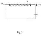
- Fig. 3 shows a schematic cross-sectional view of a known semiconductor structure.
- Reference numeral 1 denotes a semiconductor substrate of silicon, for example, p-type
- reference numeral 5 denotes a doping region on the surface OF of the semiconductor substrate 1, for example of the n-type, having a depth t 'of 10 ⁇ m.
- doping regions 5 are caused by diffusion of foreign atoms into the semiconductor substrate 1, starting from the surface OF.
- a source of dopants is deposited on the wafer surface (eg phosphorus glass for p-doping or boron glass for p-doping) and then thermally driven at high temperature, ie the dopants for diffusion into the silicon Semiconductor substrate 1 excited starting from the surface OF.
- the dopants may be incorporated into the wafer surface in a layer of typically 1 to 2 microns thickness are implanted, which is subsequently thermally diffused deeper into the silicon semiconductor substrate 1.
- Such diffusion processes are generally limited to a relatively small layer thickness starting from the surface OF of the semiconductor substrate 1, since foreign substances, such as. B. dopant atoms, diffuse only slowly in silicon, even at very high temperatures and therefore can reach in practice only depths of typically 20 to 25 microns in silicon, at least within economically acceptable diffusion times. There are also foreign atoms such. As antimony (Sb) or germanium (Ge), etc., which diffuse only extremely slowly due to their large atomic diameter, so that the specified limit of typically 20 to 25 microns in silicon can not even be achieved with these impurities, but the diffusion depths within reasonable time, on the other hand.
- Sb antimony
- Ge germanium
- thicker layers of eg silicon or silicon carbide with altered layer properties eg.
- layer properties eg.
- thick n-type monocrystalline silicon layers of, for example, 100 to 200 ⁇ m in thickness on a p-type semiconductor substrate may be cited as would be advantageously used for high-pressure sensors in silicon in conjunction with an electrochemical etch stop from p to n-type silicon.
- the problem underlying the present invention therefore consists in the provision of a method for producing a semiconductor structure, which enables a process-technically simple production of deep doping regions in a semiconductor substrate.
- the inventive method for producing a semiconductor structure according to claim 1 has the advantage that it allows the production of thick layers of crystalline semiconductor material of silicon or silicon carbide with altered properties by introducing foreign atoms or foreign substances.
- modified layers can be produced in such great thickness that they can not be economically produced in these large layer thicknesses.
- foreign atoms can be introduced, which diffuse only very slowly and therefore can not be introduced in a practical manner in layers according to the prior art, for. As antimony or germanium or other atoms with a large atomic radius.
- the idea underlying the present invention is to provide a porous region adjacent to a surface of a semiconductor substrate into which a dopant is introduced, after which the porous region is thermally recrystallized.
- Porous silicon or porous silicon carbide can be produced nanoporous or mesoporous by selecting appropriate anodization conditions, essentially current density and hydrofluoric acid concentration.
- the dopants can be supplied either in the form of a carrier gas (eg, diborane, arsine, phosphine, etc.), which penetrates into the structure.
- a carrier gas eg, diborane, arsine, phosphine, etc.
- a glass, z. B. boron glass or phosphorus glass are deposited on the surface or a dissolved in liquid precursor be impregnated into the porous structure.
- Suitable precursors are organic and inorganic compounds of boron, phosphorus (eg trimethylphosphite, phosphorus pentaxyde), arsenic (vinylarsine), antimony, germanium (tetraethylgerman), aluminum, iron, lead, etc. or their soluble salts (eg.
- the dopants are supplied in the form of a carrier gas, wherein the gas homogeneously passes through the porous region at high temperature of, for example, 900 ° C. and the impurities simultaneously diffuse from the gas phase into the nanostructure.
- the temperature treatment for deposition and the temperature treatment for driving in the dopant coincide in time.
- impregnation of the porous region with a solution of impurities in a liquid, especially in supercritical CO 2 may take place at room temperature, followed immediately by a temperature step at 900 ° C for driving and another at 950 ° C for recrystallization and Driving in take place.
- the step of driving the foreign atoms thermally is carried out separately at a temperature at which no structural rearrangement can take place yet.
- the foreign atoms diffuse into the filigree nanostructures in the entire volume of the porous structure at a temperature of, for example, 900 ° C. in silicon and penetrate them almost homogeneously.
- the stability of the nanostructure is additionally supported by the fact that natural oxides on the structural surfaces additionally stabilize them and prevent thermal rearrangement. In the case of silicon such oxides decompose above 950 ° C, in the case of silicon carbide only above 1200 ° C.
- the porous region is heated at high temperatures, e.g. from above 950 ° C in the case of silicon and from above 1200 ° C in the case of silicon carbide thermally collapsed, resulting in rearrangement of the silicon atoms or the silicon carbide again a monocrystalline massive layer in the sense of bulk material.
- This rearrangement was initially undesirable, so that the foreign atoms could still reach the nanostructure anywhere and there was no injury to individual areas of the structure.
- the native, the nanostructured oxide layers are now evaporated, which can be additionally supported by the addition of hydrogen gas. Without the stabilization by the surface oxides, the thermal rearrangement of the structure can rapidly begin and continue until a complete densification into a single crystalline material.
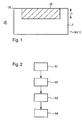
- FIG. 1a-d show schematic cross-sectional views of the essential manufacturing steps of a method for producing a semiconductor structure according to an embodiment of the present invention
- Fig. 2 FIG. 10 is a flowchart for explaining the procedure of the essential manufacturing steps of the method of manufacturing a semiconductor structure according to the embodiment of the present invention.
- Reference numeral 1 denotes a p-type silicon semiconductor substrate having a surface OF.
- a mask 2 made of silicon nitride is deposited (step S1) and subsequently a nanoporous area 10 with a depth t of 100 ⁇ m is introduced by means of an electrochemical anodization (step S2), which has a mesh of pores 10a which are interconnected Form skeleton.
- a glass 12 for example, phosphorus, first introduced into the porous region 10 at a temperature of 900 ° C, wherein at this temperature immediately at the same time a diffusion of the phosphorus in the Skeleton made of nanoscale silicon and the latter is thus penetrated homogeneously by the phosphorus.
- a temperature step S4 takes place at a temperature of more than 950 ° C., resulting in rearrangement of the silicon atoms, a thermal recrystallization of the porous region 10 in a crystalline doping region 10 'of the semiconductor substrate 1, the doping, doping concentration and doping distribution of that or those of the semiconductor substrate 1 deviates.
- the dopants may be either in the form of a carrier gas or in the form of a liquid solution which penetrates into the porous structure.
- the semiconductor structure has been formed using the silicon nitride mask in the above example, it is also possible to provide edge doping in the semiconductor substrate which laterally surrounds the porosified region and serves as an etching mask. Also, for the anodic process, a doping of the back of the substrate can be provided.
- micromechanical pressure sensor is purely exemplary and can be modified as desired.
Landscapes
- Recrystallisation Techniques (AREA)
- Pressure Sensors (AREA)
- Weting (AREA)
Applications Claiming Priority (2)
| Application Number | Priority Date | Filing Date | Title |
|---|---|---|---|
| DE102006012857A DE102006012857A1 (de) | 2006-03-21 | 2006-03-21 | Verfahren zur Herstellung einer Halbleiterstruktur und entsprechende Halbleiterstruktur |
| PCT/EP2007/052227 WO2007107461A1 (de) | 2006-03-21 | 2007-03-09 | Verfahren zur herstellung einer halbleiterstruktur und entsprechende halbleiterstruktur |
Publications (2)
| Publication Number | Publication Date |
|---|---|
| EP1999783A1 EP1999783A1 (de) | 2008-12-10 |
| EP1999783B1 true EP1999783B1 (de) | 2011-02-16 |
Family
ID=37983457
Family Applications (1)
| Application Number | Title | Priority Date | Filing Date |
|---|---|---|---|
| EP07726749A Not-in-force EP1999783B1 (de) | 2006-03-21 | 2007-03-09 | Verfahren zur herstellung einer halbleiterstruktur |
Country Status (5)
| Country | Link |
|---|---|
| US (2) | US8148234B2 (https=) |
| EP (1) | EP1999783B1 (https=) |
| JP (1) | JP5080555B2 (https=) |
| DE (2) | DE102006012857A1 (https=) |
| WO (1) | WO2007107461A1 (https=) |
Families Citing this family (3)
| Publication number | Priority date | Publication date | Assignee | Title |
|---|---|---|---|---|
| CN104118842B (zh) * | 2014-07-02 | 2017-01-18 | 上海师范大学 | 碳化硅介孔阵列材料及其制备方法 |
| US9805931B2 (en) * | 2015-08-28 | 2017-10-31 | Varian Semiconductor Equipment Associates, Inc. | Liquid immersion doping |
| CH711498B1 (fr) * | 2015-09-08 | 2020-03-13 | Nivarox Sa | Procédé de fabrication d'une pièce micromécanique horlogère et ladite pièce micromécanique horlogère. |
Family Cites Families (13)
| Publication number | Priority date | Publication date | Assignee | Title |
|---|---|---|---|---|
| JPS51132974A (en) | 1975-05-14 | 1976-11-18 | Nec Corp | Semiconductor device |
| US4262295A (en) * | 1978-01-30 | 1981-04-14 | Hitachi, Ltd. | Semiconductor device |
| JPS56130914A (en) * | 1980-03-17 | 1981-10-14 | Matsushita Electric Ind Co Ltd | Manufacture of semiconductor device |
| JPS6366929A (ja) * | 1986-09-08 | 1988-03-25 | Tokyo Ohka Kogyo Co Ltd | アンチモン拡散用シリカ系被膜形成組成物 |
| FR2655193B1 (fr) | 1989-11-30 | 1994-09-23 | Telemecanique | Dispositif semiconducteur de puissance symetrique et son procede de fabrication. |
| JP3079575B2 (ja) * | 1990-12-20 | 2000-08-21 | 株式会社日立製作所 | 半導体装置の製造方法 |
| DE4440390A1 (de) * | 1994-11-11 | 1996-05-15 | Stuttgart Mikroelektronik | Epitaxie-Verfahren zur Herstellung von Halbleiterschichtsystemen mit ultrakurzen, lateralen Dotierungsübergängen |
| WO1997040527A1 (de) | 1996-04-22 | 1997-10-30 | Siemens Aktiengesellschaft | Verfahren zur herstellung eines dotierten gebietes in einem halbleitersubstrat |
| DE10032579B4 (de) | 2000-07-05 | 2020-07-02 | Robert Bosch Gmbh | Verfahren zur Herstellung eines Halbleiterbauelements sowie ein nach dem Verfahren hergestelltes Halbleiterbauelement |
| DE10127950B4 (de) | 2001-06-08 | 2007-04-12 | Infineon Technologies Ag | Verfahren zur Herstellung eines Halbleiterbauelements und Halbleiterbauelement |
| JP2004095645A (ja) * | 2002-08-29 | 2004-03-25 | Seiko Epson Corp | 半導体装置および半導体装置の製造方法 |
| DE102004036035B4 (de) | 2003-12-16 | 2015-10-15 | Robert Bosch Gmbh | Verfahren zur Herstellung eines Halbleiterbauelements sowie ein Halbleiterbauelement, insbesondere ein Membransensor |
| JP2005259859A (ja) * | 2004-03-10 | 2005-09-22 | Toshiba Ceramics Co Ltd | 拡散ウエハおよびその製造方法 |
-
2006
- 2006-03-21 DE DE102006012857A patent/DE102006012857A1/de not_active Withdrawn
-
2007
- 2007-03-09 DE DE502007006500T patent/DE502007006500D1/de active Active
- 2007-03-09 WO PCT/EP2007/052227 patent/WO2007107461A1/de not_active Ceased
- 2007-03-09 JP JP2009500813A patent/JP5080555B2/ja not_active Expired - Fee Related
- 2007-03-09 EP EP07726749A patent/EP1999783B1/de not_active Not-in-force
- 2007-03-09 US US12/282,842 patent/US8148234B2/en not_active Expired - Fee Related
-
2012
- 2012-02-03 US US13/366,067 patent/US20120132925A1/en not_active Abandoned
Also Published As
| Publication number | Publication date |
|---|---|
| EP1999783A1 (de) | 2008-12-10 |
| DE102006012857A1 (de) | 2007-09-27 |
| US20120132925A1 (en) | 2012-05-31 |
| US20090236610A1 (en) | 2009-09-24 |
| US8148234B2 (en) | 2012-04-03 |
| WO2007107461A1 (de) | 2007-09-27 |
| JP2009537967A (ja) | 2009-10-29 |
| DE502007006500D1 (de) | 2011-03-31 |
| JP5080555B2 (ja) | 2012-11-21 |
Similar Documents
| Publication | Publication Date | Title |
|---|---|---|
| DE102006003283A1 (de) | Verfahren zur Herstellung eines Halbleiterbauelements mit unterschiedlich stark dotierten Bereichen | |
| DE102004036032A1 (de) | Verfahren zur Herstellung eines Halbleiterbauelements sowie ein Halbleiterbauelement, insbesondere ein Membransensor | |
| DE10123858A1 (de) | Verfahren zum Bilden von Silicium-haltigen Dünnschichten durch Atomschicht-Abscheidung mittels SI2CL6 und NH3 | |
| DE2030805A1 (de) | Verfahren zur Ausbildung epitaxialer Kristalle oder Plattchen in ausgewählten Bereichen von Substraten | |
| DE102012222116A1 (de) | Doppelschicht-Gate-Dielektrikum mit geringer äquivalenter Oxiddicke für Graphen-Bauelemente | |
| DE2239686A1 (de) | Verfahren zur herstellung von dielektrisch isolierten schichtbereichen aus einem siliciumhalbleitermaterial auf einer traegerschicht | |
| EP1999783B1 (de) | Verfahren zur herstellung einer halbleiterstruktur | |
| WO2010057652A1 (de) | Nonodrähte auf substratoberflächen, verfahren zu deren herstellung sowie deren verwendung | |
| DE2509585C3 (de) | Halbleiterbauelement mit mehreren epitaktischen Halbleiterschichten, insbesondere Halbleiterlaser oder Feldeffektransistor, sowie Verfahren zu dessen Herstellung | |
| DE102004036803A1 (de) | Verfahren zum Ätzen einer Schicht auf einem Substrat | |
| DE19654791B4 (de) | Verfahren und Vorrichtung zum Trennen einer Halbleiterschicht von einem Substrat | |
| DE102005010080B4 (de) | Verfahren zum Herstellen einer Dünnschicht-Struktur | |
| DE2239687B2 (de) | Verfahren zum aetzen eines mehrschichtigen halbleiterkoerpers mit einem fluessigen aetzmittel | |
| EP2491577B1 (de) | Verfahren zum ausbilden eines dotierstoffprofils | |
| WO2000052738A2 (de) | Verfahren zur herstellung hochdotierter halbleiterbauelemente | |
| DE2519360A1 (de) | Aluminiumhaltiges mittel und ein verfahren zu seinem auftragen auf ein substrat | |
| WO2007147670A1 (de) | Verfahren zur herstellung eines siliziumsubstrats mit veränderten oberflächeneigenschaften sowie ein derartiges siliziumsubstrat | |
| DE2041439A1 (de) | Verfahren zur Herstellung einer Halbleitervorrichtung | |
| EP0520214B1 (de) | Verfahren zur Herstellung eines dotierten Gebietes in einem Substrat und Anwendung bei der Herstellung eines Bipolartransistors | |
| DE1444396C3 (de) | Verfahren zum Gasplattieren durch thermische Zersetzung von Dämpfen | |
| DE102006041996B4 (de) | Verfahren zur Herstellung einer optischen Vorrichtung | |
| DE69916699T2 (de) | Verfahren zur epitaktischen Abscheidung von einer Siliziumschicht auf einem stark dotierten Siliziumsubstrat | |
| DE102017120290B3 (de) | Verfahren zum Prozessieren einer Schichtstruktur | |
| DE69509286T2 (de) | Verfahren zum Bedecken oder Füllen einer Reliefstruktur durch Abscheidung aus der Gasphase und Verwendung dieses Verfahrens für die Herstellung von Halbleiterbauelementen | |
| DE2421609C2 (de) | Halbleiteranordnung |
Legal Events
| Date | Code | Title | Description |
|---|---|---|---|
| PUAI | Public reference made under article 153(3) epc to a published international application that has entered the european phase |
Free format text: ORIGINAL CODE: 0009012 |
|
| AK | Designated contracting states |
Kind code of ref document: A1 Designated state(s): DE FR GB IT |
|
| 17P | Request for examination filed |
Effective date: 20090613 |
|
| R17P | Request for examination filed (corrected) |
Effective date: 20081021 |
|
| 17Q | First examination report despatched |
Effective date: 20100312 |
|
| DAX | Request for extension of the european patent (deleted) | ||
| RBV | Designated contracting states (corrected) |
Designated state(s): DE FR GB IT |
|
| RTI1 | Title (correction) |
Free format text: METHOD FOR FABRICATING A SEMICONDUCTOR STRUCTURE |
|
| GRAP | Despatch of communication of intention to grant a patent |
Free format text: ORIGINAL CODE: EPIDOSNIGR1 |
|
| GRAS | Grant fee paid |
Free format text: ORIGINAL CODE: EPIDOSNIGR3 |
|
| GRAA | (expected) grant |
Free format text: ORIGINAL CODE: 0009210 |
|
| AK | Designated contracting states |
Kind code of ref document: B1 Designated state(s): DE FR GB IT |
|
| REG | Reference to a national code |
Ref country code: GB Ref legal event code: FG4D Free format text: NOT ENGLISH |
|
| REF | Corresponds to: |
Ref document number: 502007006500 Country of ref document: DE Date of ref document: 20110331 Kind code of ref document: P |
|
| REG | Reference to a national code |
Ref country code: DE Ref legal event code: R096 Ref document number: 502007006500 Country of ref document: DE Effective date: 20110331 |
|
| PLBE | No opposition filed within time limit |
Free format text: ORIGINAL CODE: 0009261 |
|
| STAA | Information on the status of an ep patent application or granted ep patent |
Free format text: STATUS: NO OPPOSITION FILED WITHIN TIME LIMIT |
|
| 26N | No opposition filed |
Effective date: 20111117 |
|
| REG | Reference to a national code |
Ref country code: DE Ref legal event code: R097 Ref document number: 502007006500 Country of ref document: DE Effective date: 20111117 |
|
| PGFP | Annual fee paid to national office [announced via postgrant information from national office to epo] |
Ref country code: IT Payment date: 20140325 Year of fee payment: 8 Ref country code: FR Payment date: 20140319 Year of fee payment: 8 |
|
| PGFP | Annual fee paid to national office [announced via postgrant information from national office to epo] |
Ref country code: GB Payment date: 20140324 Year of fee payment: 8 |
|
| PGFP | Annual fee paid to national office [announced via postgrant information from national office to epo] |
Ref country code: DE Payment date: 20140523 Year of fee payment: 8 |
|
| REG | Reference to a national code |
Ref country code: DE Ref legal event code: R119 Ref document number: 502007006500 Country of ref document: DE |
|
| GBPC | Gb: european patent ceased through non-payment of renewal fee |
Effective date: 20150309 |
|
| PG25 | Lapsed in a contracting state [announced via postgrant information from national office to epo] |
Ref country code: IT Free format text: LAPSE BECAUSE OF NON-PAYMENT OF DUE FEES Effective date: 20150309 |
|
| REG | Reference to a national code |
Ref country code: FR Ref legal event code: ST Effective date: 20151130 |
|
| PG25 | Lapsed in a contracting state [announced via postgrant information from national office to epo] |
Ref country code: GB Free format text: LAPSE BECAUSE OF NON-PAYMENT OF DUE FEES Effective date: 20150309 Ref country code: DE Free format text: LAPSE BECAUSE OF NON-PAYMENT OF DUE FEES Effective date: 20151001 |
|
| PG25 | Lapsed in a contracting state [announced via postgrant information from national office to epo] |
Ref country code: FR Free format text: LAPSE BECAUSE OF NON-PAYMENT OF DUE FEES Effective date: 20150331 |