EP1997653B1 - Luftreifen - Google Patents
Luftreifen Download PDFInfo
- Publication number
- EP1997653B1 EP1997653B1 EP08009713A EP08009713A EP1997653B1 EP 1997653 B1 EP1997653 B1 EP 1997653B1 EP 08009713 A EP08009713 A EP 08009713A EP 08009713 A EP08009713 A EP 08009713A EP 1997653 B1 EP1997653 B1 EP 1997653B1
- Authority
- EP
- European Patent Office
- Prior art keywords
- rubber
- tire
- rubbers
- sidewall
- tread
- Prior art date
- Legal status (The legal status is an assumption and is not a legal conclusion. Google has not performed a legal analysis and makes no representation as to the accuracy of the status listed.)
- Ceased
Links
- 229920001971 elastomer Polymers 0.000 claims description 237
- 239000005060 rubber Substances 0.000 claims description 237
- 239000000463 material Substances 0.000 claims description 41
- 239000011324 bead Substances 0.000 claims description 33
- 239000003208 petroleum Substances 0.000 description 18
- 244000043261 Hevea brasiliensis Species 0.000 description 16
- 229920003052 natural elastomer Polymers 0.000 description 16
- 229920001194 natural rubber Polymers 0.000 description 16
- VYPSYNLAJGMNEJ-UHFFFAOYSA-N Silicium dioxide Chemical compound O=[Si]=O VYPSYNLAJGMNEJ-UHFFFAOYSA-N 0.000 description 14
- 239000006229 carbon black Substances 0.000 description 12
- 229910052751 metal Inorganic materials 0.000 description 12
- 239000002184 metal Substances 0.000 description 12
- 239000003921 oil Substances 0.000 description 10
- 235000019198 oils Nutrition 0.000 description 10
- 229920003043 Cellulose fiber Polymers 0.000 description 9
- 239000002994 raw material Substances 0.000 description 9
- 239000012744 reinforcing agent Substances 0.000 description 9
- 239000000835 fiber Substances 0.000 description 8
- 230000003014 reinforcing effect Effects 0.000 description 8
- 239000000654 additive Substances 0.000 description 7
- 239000000203 mixture Substances 0.000 description 7
- 239000000377 silicon dioxide Substances 0.000 description 7
- 239000003925 fat Substances 0.000 description 6
- ZCYVEMRRCGMTRW-UHFFFAOYSA-N 7553-56-2 Chemical compound [I] ZCYVEMRRCGMTRW-UHFFFAOYSA-N 0.000 description 5
- 229910052740 iodine Inorganic materials 0.000 description 5
- 239000011630 iodine Substances 0.000 description 5
- 238000009825 accumulation Methods 0.000 description 4
- 239000003795 chemical substances by application Substances 0.000 description 4
- 239000013078 crystal Substances 0.000 description 4
- 230000003247 decreasing effect Effects 0.000 description 4
- 239000011256 inorganic filler Substances 0.000 description 4
- 229910003475 inorganic filler Inorganic materials 0.000 description 4
- 229920003051 synthetic elastomer Polymers 0.000 description 4
- 239000005061 synthetic rubber Substances 0.000 description 4
- 235000015112 vegetable and seed oil Nutrition 0.000 description 4
- 235000019871 vegetable fat Nutrition 0.000 description 4
- 239000008158 vegetable oil Substances 0.000 description 4
- 239000005062 Polybutadiene Substances 0.000 description 3
- 229920000297 Rayon Polymers 0.000 description 3
- 229920005549 butyl rubber Polymers 0.000 description 3
- 230000000052 comparative effect Effects 0.000 description 3
- 230000007423 decrease Effects 0.000 description 3
- 230000000694 effects Effects 0.000 description 3
- 230000007257 malfunction Effects 0.000 description 3
- 150000002739 metals Chemical class 0.000 description 3
- 238000000034 method Methods 0.000 description 3
- 229920001778 nylon Polymers 0.000 description 3
- 229920002857 polybutadiene Polymers 0.000 description 3
- 239000002964 rayon Substances 0.000 description 3
- 239000004627 regenerated cellulose Substances 0.000 description 3
- 238000005096 rolling process Methods 0.000 description 3
- 229920002994 synthetic fiber Polymers 0.000 description 3
- 239000012209 synthetic fiber Substances 0.000 description 3
- VTYYLEPIZMXCLO-UHFFFAOYSA-L Calcium carbonate Chemical compound [Ca+2].[O-]C([O-])=O VTYYLEPIZMXCLO-UHFFFAOYSA-L 0.000 description 2
- 229920000433 Lyocell Polymers 0.000 description 2
- PXHVJJICTQNCMI-UHFFFAOYSA-N Nickel Chemical compound [Ni] PXHVJJICTQNCMI-UHFFFAOYSA-N 0.000 description 2
- 239000004677 Nylon Substances 0.000 description 2
- 239000003963 antioxidant agent Substances 0.000 description 2
- 230000003078 antioxidant effect Effects 0.000 description 2
- 239000010692 aromatic oil Substances 0.000 description 2
- 229920002678 cellulose Polymers 0.000 description 2
- 239000001913 cellulose Substances 0.000 description 2
- 238000005336 cracking Methods 0.000 description 2
- 238000002425 crystallisation Methods 0.000 description 2
- 230000008025 crystallization Effects 0.000 description 2
- 238000001035 drying Methods 0.000 description 2
- 235000019197 fats Nutrition 0.000 description 2
- 239000000446 fuel Substances 0.000 description 2
- 150000004676 glycans Chemical class 0.000 description 2
- 238000005259 measurement Methods 0.000 description 2
- 239000000025 natural resin Substances 0.000 description 2
- 235000014593 oils and fats Nutrition 0.000 description 2
- 229920000728 polyester Polymers 0.000 description 2
- 229920001282 polysaccharide Polymers 0.000 description 2
- 239000005017 polysaccharide Substances 0.000 description 2
- 235000005713 safflower oil Nutrition 0.000 description 2
- 239000003813 safflower oil Substances 0.000 description 2
- -1 sericite Chemical compound 0.000 description 2
- 229920003048 styrene butadiene rubber Polymers 0.000 description 2
- 238000004073 vulcanization Methods 0.000 description 2
- 238000004804 winding Methods 0.000 description 2
- RSWGJHLUYNHPMX-UHFFFAOYSA-N Abietic-Saeure Natural products C12CCC(C(C)C)=CC2=CCC2C1(C)CCCC2(C)C(O)=O RSWGJHLUYNHPMX-UHFFFAOYSA-N 0.000 description 1
- 229910000838 Al alloy Inorganic materials 0.000 description 1
- 229920002101 Chitin Polymers 0.000 description 1
- 229920001661 Chitosan Polymers 0.000 description 1
- 241000196324 Embryophyta Species 0.000 description 1
- 235000018330 Macadamia integrifolia Nutrition 0.000 description 1
- 240000000912 Macadamia tetraphylla Species 0.000 description 1
- 235000003800 Macadamia tetraphylla Nutrition 0.000 description 1
- 240000007594 Oryza sativa Species 0.000 description 1
- 235000007164 Oryza sativa Nutrition 0.000 description 1
- 235000019482 Palm oil Nutrition 0.000 description 1
- 235000019483 Peanut oil Nutrition 0.000 description 1
- 235000019484 Rapeseed oil Nutrition 0.000 description 1
- KHPCPRHQVVSZAH-HUOMCSJISA-N Rosin Natural products O(C/C=C/c1ccccc1)[C@H]1[C@H](O)[C@@H](O)[C@@H](O)[C@@H](CO)O1 KHPCPRHQVVSZAH-HUOMCSJISA-N 0.000 description 1
- 241000872198 Serjania polyphylla Species 0.000 description 1
- 229920002472 Starch Polymers 0.000 description 1
- 229910000831 Steel Inorganic materials 0.000 description 1
- 235000019486 Sunflower oil Nutrition 0.000 description 1
- GWEVSGVZZGPLCZ-UHFFFAOYSA-N Titan oxide Chemical compound O=[Ti]=O GWEVSGVZZGPLCZ-UHFFFAOYSA-N 0.000 description 1
- 229920006221 acetate fiber Polymers 0.000 description 1
- WNROFYMDJYEPJX-UHFFFAOYSA-K aluminium hydroxide Chemical compound [OH-].[OH-].[OH-].[Al+3] WNROFYMDJYEPJX-UHFFFAOYSA-K 0.000 description 1
- PNEYBMLMFCGWSK-UHFFFAOYSA-N aluminium oxide Inorganic materials [O-2].[O-2].[O-2].[Al+3].[Al+3] PNEYBMLMFCGWSK-UHFFFAOYSA-N 0.000 description 1
- 239000007864 aqueous solution Substances 0.000 description 1
- 239000004760 aramid Substances 0.000 description 1
- 229920003235 aromatic polyamide Polymers 0.000 description 1
- 238000005452 bending Methods 0.000 description 1
- 230000033228 biological regulation Effects 0.000 description 1
- 230000015572 biosynthetic process Effects 0.000 description 1
- 229910000019 calcium carbonate Inorganic materials 0.000 description 1
- 239000010495 camellia oil Substances 0.000 description 1
- 239000004359 castor oil Substances 0.000 description 1
- 235000019438 castor oil Nutrition 0.000 description 1
- 239000004927 clay Substances 0.000 description 1
- 229910052570 clay Inorganic materials 0.000 description 1
- 235000019864 coconut oil Nutrition 0.000 description 1
- 239000003240 coconut oil Substances 0.000 description 1
- 239000004020 conductor Substances 0.000 description 1
- 235000005687 corn oil Nutrition 0.000 description 1
- 239000002285 corn oil Substances 0.000 description 1
- 235000012343 cottonseed oil Nutrition 0.000 description 1
- 239000002385 cottonseed oil Substances 0.000 description 1
- 238000013461 design Methods 0.000 description 1
- 230000006866 deterioration Effects 0.000 description 1
- 230000005611 electricity Effects 0.000 description 1
- 230000007613 environmental effect Effects 0.000 description 1
- ZEMPKEQAKRGZGQ-XOQCFJPHSA-N glycerol triricinoleate Natural products CCCCCC[C@@H](O)CC=CCCCCCCCC(=O)OC[C@@H](COC(=O)CCCCCCCC=CC[C@@H](O)CCCCCC)OC(=O)CCCCCCCC=CC[C@H](O)CCCCCC ZEMPKEQAKRGZGQ-XOQCFJPHSA-N 0.000 description 1
- 238000009413 insulation Methods 0.000 description 1
- 229940119170 jojoba wax Drugs 0.000 description 1
- 239000000944 linseed oil Substances 0.000 description 1
- 235000021388 linseed oil Nutrition 0.000 description 1
- 229910003002 lithium salt Inorganic materials 0.000 description 1
- 159000000002 lithium salts Chemical class 0.000 description 1
- ZLNQQNXFFQJAID-UHFFFAOYSA-L magnesium carbonate Chemical compound [Mg+2].[O-]C([O-])=O ZLNQQNXFFQJAID-UHFFFAOYSA-L 0.000 description 1
- 239000001095 magnesium carbonate Substances 0.000 description 1
- 229910000021 magnesium carbonate Inorganic materials 0.000 description 1
- VTHJTEIRLNZDEV-UHFFFAOYSA-L magnesium dihydroxide Chemical compound [OH-].[OH-].[Mg+2] VTHJTEIRLNZDEV-UHFFFAOYSA-L 0.000 description 1
- 239000000347 magnesium hydroxide Substances 0.000 description 1
- 229910001862 magnesium hydroxide Inorganic materials 0.000 description 1
- 239000000395 magnesium oxide Substances 0.000 description 1
- CPLXHLVBOLITMK-UHFFFAOYSA-N magnesium oxide Inorganic materials [Mg]=O CPLXHLVBOLITMK-UHFFFAOYSA-N 0.000 description 1
- AXZKOIWUVFPNLO-UHFFFAOYSA-N magnesium;oxygen(2-) Chemical compound [O-2].[Mg+2] AXZKOIWUVFPNLO-UHFFFAOYSA-N 0.000 description 1
- 239000007769 metal material Substances 0.000 description 1
- 238000002156 mixing Methods 0.000 description 1
- 238000012986 modification Methods 0.000 description 1
- 230000004048 modification Effects 0.000 description 1
- 229910052759 nickel Inorganic materials 0.000 description 1
- 239000010466 nut oil Substances 0.000 description 1
- 239000004006 olive oil Substances 0.000 description 1
- 235000008390 olive oil Nutrition 0.000 description 1
- 239000012766 organic filler Substances 0.000 description 1
- 239000003346 palm kernel oil Substances 0.000 description 1
- 235000019865 palm kernel oil Nutrition 0.000 description 1
- 239000002540 palm oil Substances 0.000 description 1
- 239000010690 paraffinic oil Substances 0.000 description 1
- 239000000312 peanut oil Substances 0.000 description 1
- 239000011846 petroleum-based material Substances 0.000 description 1
- 239000010665 pine oil Substances 0.000 description 1
- 239000011297 pine tar Substances 0.000 description 1
- 229940068124 pine tar Drugs 0.000 description 1
- 229920006149 polyester-amide block copolymer Polymers 0.000 description 1
- 230000002787 reinforcement Effects 0.000 description 1
- 235000009566 rice Nutrition 0.000 description 1
- 235000011803 sesame oil Nutrition 0.000 description 1
- 239000008159 sesame oil Substances 0.000 description 1
- 239000000344 soap Substances 0.000 description 1
- 235000002316 solid fats Nutrition 0.000 description 1
- 235000012424 soybean oil Nutrition 0.000 description 1
- 239000003549 soybean oil Substances 0.000 description 1
- 239000008107 starch Substances 0.000 description 1
- 235000019698 starch Nutrition 0.000 description 1
- 230000003068 static effect Effects 0.000 description 1
- 239000010959 steel Substances 0.000 description 1
- 239000002600 sunflower oil Substances 0.000 description 1
- 239000000454 talc Substances 0.000 description 1
- 229910052623 talc Inorganic materials 0.000 description 1
- 239000003784 tall oil Substances 0.000 description 1
- 238000012360 testing method Methods 0.000 description 1
- OGIDPMRJRNCKJF-UHFFFAOYSA-N titanium oxide Inorganic materials [Ti]=O OGIDPMRJRNCKJF-UHFFFAOYSA-N 0.000 description 1
- KHPCPRHQVVSZAH-UHFFFAOYSA-N trans-cinnamyl beta-D-glucopyranoside Natural products OC1C(O)C(O)C(CO)OC1OCC=CC1=CC=CC=C1 KHPCPRHQVVSZAH-UHFFFAOYSA-N 0.000 description 1
- 239000002383 tung oil Substances 0.000 description 1
- 239000003981 vehicle Substances 0.000 description 1
- 239000001993 wax Substances 0.000 description 1
Images


Classifications
-
- B—PERFORMING OPERATIONS; TRANSPORTING
- B60—VEHICLES IN GENERAL
- B60C—VEHICLE TYRES; TYRE INFLATION; TYRE CHANGING; CONNECTING VALVES TO INFLATABLE ELASTIC BODIES IN GENERAL; DEVICES OR ARRANGEMENTS RELATED TO TYRES
- B60C19/00—Tyre parts or constructions not otherwise provided for
- B60C19/08—Electric-charge-dissipating arrangements
Definitions
- the present invention relates to a pneumatic tire capable of preventing electrostatic accumulation, more particularly to a pneumatic tire having in a sidewall portion an electrically conducting path formed by a ribbon-like electrically conductive rubber strip extending linearly in a radial direction.
- tire-constituting components occupying 50 % or more of the overall weight of a tire are made of petroleum-based materials derived from petroleum as a raw material.
- general radial tires for passenger cars contain about 20 % by weight or more of a synthetic rubber, about 20 % by weight or more of a carbon black, and others, e.g., a petroleum-based oil such as aromatic oil and a synthetic fiber, based on the overall tire weight.
- JP-A-2003-063206 proposes an ecological tire comprising raw materials derived from non-petroleum resources in an amount of at least 75 % by weight based on the total weight of the tire.
- a means for preventing electrostatic accumulation is known, for example, from JP-A-2007-008269 (which is considered as the closest prior art document) wherein, as conceptually shown in Fig. 9 , an electrically conducting rubber layer "a" is disposed between a carcass and a sidewall rubber to provide electric continuity between a tread ground contact surface and a rim.
- this electrically conducting rubber layer "a” is formed over the whole circumference of a tire, its volume is relatively large. Since this layer requires the use of carbon black, the proposed tire does not sufficiently meet the need of utilization of non-petroleum resources in tires.
- a pneumatic tire comprising at least 75 % by weight, based on the overall weight of the tire, of tire-constituting components made of nonpetroleum-based materials, said tire comprising a carcass extending from a tread portion to each of bead cores in a pair of bead portions through a pair of sidewall portions, and tire rubber members including a tread rubber disposed radially outward of said carcass to provide an outer surface of said tread portion, a pair of sidewall rubbers disposed axially outward of said carcass to provide an outer surface of said sidewall portions, and a pair of clinch rubbers forming an outer surface of said bead portions, wherein said tread rubber comprises a cap rubber which provides a ground contact surface of said tread portion, a base rubber disposed radially inward of said cap rubber, and a pair of wing rubbers disposed axially outward of said cap rubber, a boundary surface between said cap rubber and each of said wing rubbers has
- volume resistivity denotes a value measured by an electric resistance meter ADVANTESTER 8340A available from Advantest Co. under conditions of applied voltage 500 V, temperature 25°C and humidity 50 % using a rubber specimen of 15 cm ⁇ 15 cm ⁇ 2 mm (thickness).
- ground contact surface or "tread ground contact surface” as used herein denotes a region in the tread surface which can come into contact with the ground when a tire is mounted on a standard rim and inflated to a normal inner pressure and this tire in the normal inner pressure state is then loaded with a normal load. Further, the maximum axial width of this ground contact surface is herein called “ground contact width” or “tread ground contact width”.
- rim contact region denotes a region in the outer surface of the bead portion, which comes into contact with a rim in the normal inner pressure state.
- standard rim denotes a rim defined for every tire in a standardizing system on which the tire is based and is, for example, “standard rim” in JATMA, "Design Rim” in TRA and “Measuring Rim” in ETRTO.
- normal inner pressure denotes an air pressure defined for every tire in the standardizing system and is, for example, the “maximum air pressure” in JATMA, the maximum value recited in the table of "Tire Load Limits at Various Cold Inflation Pressures" in TRA, and the “Inflation Pressure” in ETRTO", provided that in case of tires for passenger cars, the "normal inner pressure” is 180 kPa.
- normal load denotes a load defined for every tire in the standardizing system and is, for example, the maximum load capacity in JATMA, the maximum value recited in the table of "Tire Load Limits at Various Cold Inflation Pressures" in TRA, and the “Load Capacity” in ETRTO.
- the pneumatic tires of the present invention having a structure as mentioned above can reduce the electric resistance while suppressing the amount of carbon black as small as possible, and can prevent radio disturbance, electrical malfunction and so on, which are caused by electrostatic accumulation, while achieving utilization of nonpetroleum-based materials in high proportions.
- a pneumatic tire according to the present invention at least 75 % by weight of tire-constituting components or materials based on the overall weight of the tire are made of nonpetroleum-based materials, in other words, raw materials derived from nonpetroleum resources.
- a pneumatic tire 1 is provided at least with a carcass 6 extending from a tread portion 2 to each of bead cores 5 in opposing bead portions 4 through sidewall portions 3; and tire rubber members G including, at least, a tread rubber 2G disposed radially outward of the carcass 6 to provide an outer surface of the tread portion 2, a pair of sidewall rubbers 3G disposed axially outward of the carcass 6 to provide an outer surface of the sidewall portions 3, and a pair of clinch rubbers 4G forming an outer surface of the bead portions 4.
- the carcass 6 comprises at least one carcass ply 6A (in this embodiment, one carcass ply) in which carcass cords are disposed at an angle of 70 to 90° with respect to the tire circumferential direction and are covered with a topping rubber.
- the carcass ply 6A is composed of a toroidal main portion 6a that extends from one bead core 5 to the opposing bead core 5, passing through a crown region of the tire, and turnup portions 6b that are continuous with the both ends of the main portion 6a and are turned up around the bead cores 5 from the axially inside toward the axially outside of the tire to thereby anchor the carcass ply.
- a bead apex rubber 8 that extends radially outwardly from the bead core 5 in a tapered manner.
- Each of the bead cores 5 comprises a ring body which is formed, for instance, by winding a bead wire 5w multiple times to have a predetermined cross sectional shape. It serves to sufficiently ensure engagement with a rim R and to enhance the steering stability and the bead durability.
- a tread-reinforcing cord layer 10 is disposed radially outward of the carcass 6 in the tread portion 2.
- the tread-reinforcing cord layer 10 comprises a belt 7 superposed on the carcass 6 and a band 9 superposed on the belt 7.
- the belt 7 comprises at least two plies of belt cords which are arranged at an angle of, for instance, 15 to 40° with respect to the tire circumferential direction and covered with a topping rubber.
- the belt 7 shown in this embodiment comprises two belt plies 7A and 7B.
- the belt plies are stacked so that the belt cords in one ply cross the cords in the other belt ply, whereby the rigidity of the belt is raised to reinforce the tread portion 2 over approximately full width thereof by a hoop effect.
- the band 9 comprises at least one band ply 9A of a band cord which is spirally wound at an angle of at most 5° with respect to the tire circumferential direction and covered with a topping rubber.
- the band 9 binds the belt 7 to enhance the steering stability, high speed durability and the like.
- As the band ply 9A are adoptable a pair of right and left edge band plies which are disposed to cover only axially outer edge portions of the belt 7, a full band ply which covers approximately full width of the belt 7, and a combination of them.
- the band 9 shown in this embodiment comprises one full band ply.
- the tread-reinforcing cord layer 10 may be composed of only the belt 7 or only the band 9.
- a reinforcing ply (now shown) of reinforcing cords covered with a topping rubber may be additionally disposed in the bead portion 4 and/or the sidewall portion 3, as occasion demands.
- the clinch rubber 4G is made of a high modulus rubber which is superior in wear resistance, as well known in the art.
- the clinch rubber extends radially outwardly from a bead heel to form the outer surface of the bead portion 4 including at least a region RS contacting a rim flange Rf (hereinafter referred to as rim-contacting region RS).
- the clinch rubber 4G serves to prevent damage of the bead portion owing to slippage of the rim.
- the sidewall rubber 3G is made of a relatively low modulus rubber which is superior in bending resistance. It flexibly bends to follow tire deformation to thereby prevent generation of cracks in the outer surface of the sidewall portion 3.
- a radially inner edge portion of the sidewall rubber 3G is in contact with the clinch rubber 4G to form a boundary surface Q1 which extends from a radially inner end point PL on the outer surface of the sidewall portion 3 toward the carcass 6, particularly to a point PC on the outer surface of the carcass turnup portion 6b, approximately parallel to the tire equator plane or with slightly inclining axially inwardly.
- a radially outer edge portion of the sidewall rubber 3G is formed into a so-called TOS (tread over sidewall) structure in which the radially outer edge portion of the sidewall rubber 3G is covered with an axially outer edge portion of the tread rubber 2G. Therefore, the sidewall rubber 3G and the tread rubber 2G are in contact with each other to form a boundary surface Q2 which extends from a radially outer end point PU on the outer surface of the sidewall portion 3 to an axially outer edge of the belt 7 with inclining radially outwardly.
- the tread rubber 2G comprises a cap rubber 2G 1 which provides a ground contact surface 2S of the tread portion 2, a base rubber 2G2 disposed radially inward of the cap rubber 2G1, and a pair of wing rubbers 2G3 disposed axially outward of the cap rubber 2G1.
- An axially outer edge portion of the tread rubber 2G is bent radially inwardly so that it locates axially outward of an axially outer edge of the tread-reinforcing cord layer 10 and an axially outer edge portion of the base rubber 2G2 is located axially inward of an axially outer edge portion of the cap rubber 2G1.
- the tread rubber 2G can be produced using a known three layer co-extruder by which cap rubber 2G1, base rubber 2G2 and wing rubber 2G3 are co-extruded to form an integrated single body.
- a boundary surface Q3 between the cap rubber 2G1 and the wing rubber 2G3 has an exposing end Q3p which exposes at the outer surface of the tread portion 2.
- the axial distance L from the exposing end Q3p to the tire equator C is not less than 0.4 times the tread ground contact width TW and less than 0.5 times the tread ground contact width TW. That is to say, the wing rubber 2G3 extends axially inwardly beyond a tread ground contact edge Te so that an axially inner edge portion of the wing rubber is located in a ground contact region.
- a part of the wing rubber 2G3 can contact the ground when running. If the distance L is less than 0.4 times the ground contact width TW (L/TW ⁇ 0.4), uneven wear occurs between the cap rubber 2G1 and the wing rubber 2G3 to deteriorate the appearance. If the distance L is not less than 0.5 times the ground contact width TW, the wing rubber 2G3 does not surely contact the ground. Therefore, preferably the distance L is at least 0.42 times the ground contact width TW and at most 0.46 times the ground contact width TW.
- the wing rubber 2G3 is in the form of a sheet having a thickness of 0.5 to 2.0 mm. Therefore, its rubber volume is kept low, but the wing rubber 2G3 can surely contact the ground even in the case that the tread rubber 2G is worn away, since the radially outer edge portion of the wing rubber is located axially inward of the tread ground contact edge Te.
- carcass cords bead wire, belt cords, band cords, reinforcing cords and so on may be generically called "tire cords”.
- the tire rubber members G include, for instance, besides the above-mentioned tread rubber 2G, sidewall rubber 3G and clinch rubber 4G, an inner liner rubber (not shown) which forms a tire cavity surface, the bead apex rubber 8, and topping rubbers used for respective plies.
- nonpetroleum-based materials as used herein means materials derived from raw materials other than petroleum and encompasses, for instance, metals, natural rubber, inorganic fillers and/or biofillers, natural fats and oils, natural resins, natural waxes, natural fibers, processed products of these materials, and the like.
- cords made of nonpetroleum-based materials are used for a part or all of the tire cords.
- synthetic fiber cords made of raw materials derived from petroleum resources, e.g., nylon polyester and aromatic polyamide.
- a part or all of such synthetic fiber cords are replaced with cords made of nonpetroleum-based materials.
- the cords made of nonpetroleum-based materials can be used metal cords made of metals and natural fiber cords made of natural fibers or processed products thereof. Natural fiber cords are preferred from the viewpoint of suppressing increase of fuel consumption owing to weight increase.
- the natural fiber cords can be suitably used cords of regenerated cellulose fibers such as rayon, cuprammonium rayon (cupro) and acetate fibers, and cords of refined cellulose fibers such as lyocell (available under the trade mark "Tencel” from Lenzing AG).
- regenerated cellulose fibers and refined cellulose fibers have a high breaking strength comparable to nylon fibers and polyester fibers and, therefore, are suitable for use as a tire cord.
- the refined cellulose fibers have a feature of having a high modulus, since the degree of crystallization thereof is high as compared with the regenerated cellulose fibers and the orientation of crystal portion and non-crystal portion is high.
- the refined cellulose fibers have the feature that moisture is hard to enter between cellulose molecular chains and therefore the stability of strength and elongation to moisture is high, whereas rayon tends to cause deterioration of strength owing to moisture. Therefore, the stability of strength and elongation to moisture can be enhanced by using the refined cellulose fiber cords as a carcass cord and/or a band cord.
- the refined cellulose fiber cords is not mere replacement with petroleum-based fiber cords, but produces an effect of improving the high speed durability and the high speed steering stability as compared with conventional tires using nylon cords, polyester cords and so on.
- metal cords e.g., steel cords, as carcass cords or reinforcing cords in the same manner as conventional heavy duty tires.
- Metal cords and metal wires have been conventionally used as belt cords or bead wires.
- the metal cords or wires are applied to the belt cords and bead wires in the same manner as conventional tires. From the viewpoint of preventing the fuel cost from increasing owing to increase in weight, it is preferable to use metal cords and wires in an amount of at most 20 % by weight based on the overall weight of the tire.
- the tire rubber members G are produced from various rubber compositions containing a rubber component and additives known for use in tires.
- a part or all of the rubber component and a part or all of the additives are constituted by nonpetroleum-based materials.
- the rubber component a blend of a nonpetroleum-based material, natural rubber, with a synthetic rubber prepared from a raw material derived from a petroleum resource, such as styrene-butadiene rubber (SBR), butadiene rubber (BR) or butyl rubber (IIR).
- Natural rubber (including modified natural rubbers) is used as a rubber made of a nonpetroleum-based material.
- a typical example of the modified natural rubber is an epoxidized natural rubber.
- the epoxidized natural rubber tends to have superior performances such as grip performance, low rolling resistance and flex cracking resistance. Accordingly, a blend of natural rubber and epoxidized natural rubber can be suitably used in various tire rubber members which require different properties from each other, by suitably changing the blending ratio.
- Examples of the additives to be incorporated into the tire rubber members G are, for instance, a reinforcing agent, a softener, a vulcanizing agent, a vulcanization accelerator, an antioxidant, a tackifier, and the like.
- a reinforcing agent for instance, a softener, a vulcanizing agent, a vulcanization accelerator, an antioxidant, a tackifier, and the like.
- reinforcing agent, softener and vulcanizing agent are added to a rubber component as essential components, and other additives are used as occasion demands.
- a carbon black prepared using a petroleum resource as a raw material As a reinforcing agent has been conventionally used a carbon black prepared using a petroleum resource as a raw material, from the viewpoint of reinforcing effect.
- the amount of carbon black is about 20 % by weight or more based on the overall weight of a tire.
- a part or all of the carbon black is replaced with a nonpetroleum-based reinforcing agent, i.e., an inorganic filler and/or a biofiller.
- the inorganic filler are, for instance, silica, sericite, calcium carbonate, clay, alumina, talc, magnesium carbonate, aluminum hydroxide, magnesium hydroxide, magnesium oxide, titanium oxide, and the like.
- biofiller examples include, for instance, plant-derived polysaccharides such as starch and cellulose, and animal-derived polysaccharides such as chitin and chitosan. Of these, silica is preferred from the viewpoint of ensuring the effect of reinforcing a rubber.
- a softener have been conventionally used petroleum-based oils such as paraffinic oils, aromatic oils and naphthenic oils which are derived from petroleum resources.
- the petroleum-based oils are generally used in an amount of about 8 % by weight based on the overall weight of a tire.
- a part or all of the petroleum-based oils are replaced by a nonpetroleum-based softener, i.e., natural oils and fats. Vegetable oils and fats can be used as the natural oils and fats.
- vegetable oils and fats are, for instance, castor oil, cotton seed oil, linseed oil, rape seed oil, soybean oil, palm oil, coconut oil, peanut oil, rosin, pine oil, pine tar, tall oil, corn oil, rice oil, safflower oil, sesame oil, olive oil, sunflower oil, palm kernel oil, camellia oil, jojoba oil, macadamia nut oil, safflower oil and tung oil.
- vegetable oils and fats having a low degree of unsaturation are preferred, e.g., semi-drying oils having an iodine number of 100 to 130, non-drying oils having an iodine number of at most 100, and solid fats.
- the "iodine number” denotes the number of grams of iodine absorbed by 100 g of sample. If the iodine number of vegetable oils and fats is more than 130, there is a tendency that the loss factor (tan ⁇ ) increases and the hardness decreases, thus causing increase of rolling resistance and decrease of steering stability.
- additives such as vulcanizing agent, vulcanization accelerator, antioxidant and tackifier have a great influence on rubber properties, although the amounts thereof are very small as compared with the reinforcing agent and the softener. Therefore, as these additives, conventionally used ones are preferably used in the present invention.
- At least the cap rubber 2G1, the base rubber 2G2, the sidewall rubber 3G and the topping rubber of carcass 6 are formed of insulating rubber materials which contains an organic filler such as silica as a reinforcing agent to have a volume resistivity of at least 1 ⁇ 10 8 ⁇ cm.
- an organic filler such as silica as a reinforcing agent to have a volume resistivity of at least 1 ⁇ 10 8 ⁇ cm.
- rubber members other than the wing rubber 2G3 and a ribbon-like electrically conductive rubber strip 21 (shown in Fig. 1 ) for forming an electrically conducting path 20 described after are prepared from the insulating rubber materials.
- the wing rubber 2G3 and the electrically conductive rubber strip 21 are formed of electrically conductive rubber materials having a volume resistivity of at most 1 ⁇ 10 7 ⁇ cm for the purpose of decreasing the electric resistance.
- the volume resistivity is decreased usually by using a large amount of carbon black as a reinforcing agent, but it may be used in combination with an ionic conductive material such as a lithium salt or a metal material such as nickel in order to decrease the volume resistivity within the above-mentioned range.
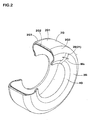
- At least one electrically conducting path 20 (in the present embodiment, one conducting path 20) made of an electrically conductive rubber strip 21 is formed in the sidewall portion 3, as shown in Figs. 1 and 2 , in order to achieve electric conduction between the wing rubber 2G3 and the rim R.
- the electrically conductive rubber strip 21 is a ribbon-like material having a width Ws (shown in Figs. 2 and 3 ) of 10 to 40 mm.
- a radially outer end portion of the strip 21 (conducting path 20) has a conducting part 21A which is in contact with the wing rubber 2G3.
- the conductive rubber strip 21 (conducting path 20) extends straight from the wing rubber-contacting part 21A in a radially inward direction through an axial outside of the carcass 6.
- the radially outer end portion of the conductive rubber strip 21 is disposed at the boundary surface Q2 between the sidewall rubber 3G and the tread rubber 2G to form a nip-holding portion 21a which is sandwiched between the sidewall rubber 3G and the tread rubber 2G and held thereby.
- the conducting part 21A which is in contact with the wing rubber 2G3 is located at a part of the nip-holding portion 21a.
- the conductive rubber strip 21 (conducting path 20) has a main portion 21b which is continuous with the nip-holding portion 21a and extends radially inwardly while contacting the outer surfaces of the sidewall rubber 3G and the clinch rubber 4G.
- a lower end portion 21b1 of the main portion 21 b can terminate to expose at the rim-contacting region RS of the clinch rubber 4G.
- an insulating rubber material can be used for the clinch rubber 4G.
- the conductive rubber strip 21 (conducting path 20) electrically connects the wing rubber 2G3 and the rim R at a minimal distance, it exhibits an excellent conducting performance and accordingly can sufficiently lower the electric resistance of a tire in spite of a single narrow-width ribbon-like material having a width Ws of 10 mm or less.
- the outer end portion (nip-holding portion 21a) of the rubber strip 21 (conducting path 20) is sandwiched between the tread rubber 2G and the sidewall rubber 3G so as to contact the wing rubber 2G3 at the conducting part 21A. Therefore, stable electric conduction with the wing rubber 2G3 is secured.
- the radially inner end portion of the rubber strip 21 which is located at the rim-contacting region RS is always in contact with the rim R with pressure, stable electric conduction with the rim R is also secured although the strip 21 is a single narrow-width ribbon-like material.
- the width Ws of the rubber strip 21 is less than 10 mm, the conducting performance tends to be insufficient for sufficiently lower the electric resistance. If the width Ws is more than 40 mm, the volume of the rubber strip 21 and the amount of carbon black incorporated therein unnecessarily increase. From the same viewpoints, it is preferable that the thickness of the electrically conductive rubber strip 21 is from 0.5 to 2.0 mm.
- the conducting rubber strip 21 (conductive path 20) has a narrow width, it does not exert a bad influence on the tire performances including uniformity. Therefore, unbalanced arrangement of the conducting path 20 is possible.
- the conducting path 20 may be formed in only one of a pair of sidewall portions 3 and/or only single conducting path 20 may be formed.
- the conductive rubber strip 21 is preferably embedded in the sidewall rubber 3G so that the surface of the rubber strip 21 forms a single flat surface with the surface of the sidewall rubber 3G and the surface of the clinch rubber 4G.
- the clinch rubber 4G may be formed of an electrically conductive rubber material, although it is undesirable from the viewpoint of increasing the proportion of nonpetroleum-based materials in tires.
- the radially inner end of the conducting path 20 may terminate at a location radially outward of the rim-contacting region RS so long as the radially inner end portion 21 b 1 of the main portion 21b is in contact with the clinch rubber 4G.
- the conducting path 20 is electrically connected to the rim R through the conductive clinch rubber 4G.
- the sidewall rubber 3G is formed, for example, by winding a raw rubber sheet for sidewall rubber around a tire forming drum in the circumferential direction of tire. Therefore, as shown in Fig. 5 , the conducting path 20 can also be formed by interposing the conductive rubber strip 21 between a wind starting end portion E1 of the raw rubber sheet for sidewall rubber and a wind finishing end portion E2 of the raw rubber sheet. One edge of the rubber strip 21 comes into contact with the carcass 6, and the other edge exposes at the outer surface of the sidewall portion 3. In this case, the exposing area of the conducting path 20 can be decreased.
- a conducting path 20 is formed in a pneumatic tire 1 having a so-called SOT (sidewall over tread) structure.
- SOT sidewall over tread
- an axially edge portion of the tread rubber 2G is covered with a radially outer edge portion of the sidewall rubber 3G, and the tread rubber 2G and the sidewall rubber 3G are in contact with each other to form a boundary surface Q2 which extends from a radially outer end point PU on the outer surface of the sidewall portion 3 to a radially inner end point PL on the carcass 6.
- the conductive rubber strip 21 (conducting path 20) is composed of a nip-holding portion 21 a which is located at the boundary surface Q2 and sandwiched between the sidewall rubber 3G and the tread rubber 2G (wing rubber 2G3), and a main portion 21b which is continuous with the nip-holding portion 21a and extends radially inwardly through a location between the carcass 6 and the sidewall rubber 3G and a location between the carcass 6 and the clinch rubber 4G.
- a lower end portion 21b1 of the main portion 21 b is exposed at a bead bottom 4S to achieve electric conduction with the rim R, as shown in Fig. 7(A) .
- the lower end portion 21b1 may be passed through the clinch rubber 4G and be exposed at the rim-contacting region RS.
- Pneumatic tires (size: 215/ 45ZR 17) having a base structure shown in Fig. 1 were manufactured based on the specifications shown in Table 1, and the electric resistance thereof was measured by the method described below. Specifications of tires which are not described in the table are common to all tires.
- rubber members other than a wing rubber and a conductive rubber strip for electric conduction were formed of an insulating rubber member containing 30 parts by weight of silica per 100 parts by weight of a rubber component (natural rubber) and having a volume resistivity of 1 ⁇ 10 8 ⁇ cm or more.
- the wing rubber and the conductive rubber strip were formed of an electrically conductive rubber member containing 30 parts by weight of carbon black per 100 parts by weight of a rubber component (natural rubber) and having a volume resistivity of 8.0 ⁇ 10 5 ⁇ cm.
- the electric resistance of a tire-rim assembly was measured according to a JATMA standard by using a measuring apparatus having, as shown in Fig. 8 , a grounded insulating plate 51, a conductive metal plate 52 mounted on the insulating plate 51, a tire mounting shaft 53 for holding an assembly of a tire T and a rim R, and an electric resistance meter 54.
- the measuring range of the electric resistance meter 54 is from 1.0 ⁇ 10 3 to 1.6 ⁇ 10 16 .
- the surface of the metal plate 52 was smoothly polished and its electric resistance was set to 10 ⁇ or less.
- the electric resistance of the insulating plate 51 was set to 10 12 ⁇ or more.
- the measurement was made at a temperature of 25°C and a humidity of 50 % according to the following procedures.
Landscapes
- Engineering & Computer Science (AREA)
- Mechanical Engineering (AREA)
- Tires In General (AREA)
Claims (10)
- Luftreifen (1), der zumindest 75 Gew.-%, bezogen auf das Gesamtgewicht des Reifens, reifenbildende Bestandteile umfasst, die aus nicht auf Mineralöl basierenden Materialien hergestellt sind, wobei der Reifen eine Karkasse (6), die sich von einem Laufflächenabschnitt (2) zu einem jeden von Wulstkernen (5) in einem Paar Wulstabschnitten (4) durch ein Paar Seitenwandabschnitte (3) erstreckt, und Reifenkautschukelemente (G) umfasst, die einen Laufflächenkautschuk (2G), der radial außen von der Karkasse angeordnet ist, um eine Außenfläche des Laufflächenabschnitts vorzusehen, ein Paar Seitenwandkautschuke (3G), die axial außen von der Karkasse angeordnet sind, um eine Außenfläche der Seitenwandabschnitte vorzusehen, und ein Paar Abriebstreifenkautschuke (4G) umfassen, die eine Außenfläche der Wulstabschnitte (4) bilden,
wobei der Laufflächenkautschuk einen Deckkautschuk (2G1), der eine Bodenkontaktfläche (2S) des Laufflächenabschnitts (2) bereitstellt, einen Basiskautschuk (2G2), der radial innen von dem Deckkautschuk angeordnet ist, und ein Paar Flügelkautschuke (2G3) umfasst, die axial außen von dem Deckkautschuk angeordnet sind,
eine Grenzfläche (Q3) zwischen dem Deckkautschuk (2G1) und jedem der Flügelkautschuke (2G3) ein freigelegtes Ende (Q3P) aufweist, das an der Außenfläche des Laufflächenabschnitts freigelegt ist, und der axiale Abstand L von dem freigelegten Ende zu dem Reifenäquator (C) nicht kleiner als das 0,4-fache einer Laufflächenbodenkontaktbreite (TW) und kleiner als das 0,5-fache der Laufflächenbodenkontaktbreite ist, und
wobei ein jeder von dem Basiskautschuk, dem Deckkautschuk, den Seitenwandkautschuken und einem Gummierungskautschuk der Karkasse aus einem isolierenden Kautschukmaterial gebildet ist, das einen spezifischen Volumenwiderstand von zumindest 1 x 10⁸ Ωcm aufweist, und die Flügelkautschuke (2G3) aus einem elektrisch leitfähigen Kautschukmaterial gebildet sind, das einen spezifischen Volumenwiderstand von höchstens 1 x 10⁷ Ωcm aufweist, und
die Seitenwandabschnitte (3) mit zumindest einer elektrisch leitenden Strecke (20) versehen sind, die aus einem bandartigen, leitfähigen Kautschukstreifen (21) gebildet ist, der aus einem elektrisch leitfähigen Kautschukmaterial hergestellt ist, das einen spezifischen Volumenwiderstand von höchstens 1 x 10⁷ Ωcm aufweist, und der eine Breite Ws von 10 bis 40 mm aufweist, in welchem ein radial äußerer Endabschnitt des leitfähigen Kautschukstreifens einen elektrisch leitenden Teil bereitstellt, der mit einem der Flügelkautschuke (2G3) in Kontakt steht, und der leitfähige Kautschukstreifen sich geradlinig in einer Richtung radial nach innen von dem elektrisch leitenden Teil erstreckt, so dass er einen der Abriebstreifenkautschuke (4G) erreicht. - Luftreifen nach Anspruch 1,
wobei der leitfähige Kautschukstreifen eine Dicke von 0,5 bis 2,0 mm aufweist. - Luftreifen nach Anspruch 1 oder 2,
wobei der leitfähige Kautschukstreifen derart angeordnet ist, dass er an der Außenfläche des Seitenwandabschnitts freigelegt ist. - Luftreifen nach Anspruch 1 oder 2,
wobei der leitfähige Kautschukstreifen derart angeordnet ist, dass er zwischen der Karkasse und dem Seitenwandkautschuk verläuft. - Luftreifen nach einem der Ansprüche 1 bis 4,
wobei die Abriebstreifenkautschuke aus einem elektrisch leitfähigen Kautschukmaterial gebildet sind, und ein radial innerer Endabschnitt des leitfähigen Kautschukstreifens unter Kontaktierung des Abriebstreifenkautschuks endet. - Luftreifen nach einem der Ansprüche 1 bis 4,
wobei die Abriebstreifenkautschuke aus einem elektrisch isolierenden Kautschukmaterial gebildet sind, und ein radial innerer Endabschnitt des leitfähigen Kautschukstreifens derart endet, dass er an einem Felgenkontaktbereich freigelegt ist, an welchem die Außenfläche des Wulstabschnitts mit einer Felge in Kontakt gelangt. - Luftreifen nach einem der Ansprüche 1 bis 4,
wobei die Abriebstreifenkautschuke aus einem elektrisch isolierenden Kautschukmaterial gebildet sind, und ein radial innerer Endabschnitt des leitfähigen Kautschukstreifens derart endet, dass er an der Unterseite des Wulstabschnitts freigelegt ist. - Luftreifen nach Anspruch 6 oder 7,
wobei andere Reifenkautschukelemente als die Flügelkautschuke und der leitfähige Kautschukstreifen aus einem isolierenden Kautschukmaterial gebildet sind. - Luftreifen nach einem der Ansprüche 1 bis 8,
wobei der radial äußere Endabschnitt des leitfähigen Kautschukstreifens zwischen dem Laufstreifenkautschuk und dem Seitenwandkautschuk geschichtet angeordnet ist. - Luftreifen nach einem der Ansprüche 1 bis 9,
wobei der leitfähige Kautschukstreifen derart angeordnet ist, dass eine Kante davon in Kontakt mit der Karkasse steht und die andere Kante an der Außenfläche des Seitenwandabschnitts freigelegt ist.
Applications Claiming Priority (1)
| Application Number | Priority Date | Filing Date | Title |
|---|---|---|---|
| JP2007142216A JP4348380B2 (ja) | 2007-05-29 | 2007-05-29 | 空気入りタイヤ |
Publications (2)
| Publication Number | Publication Date |
|---|---|
| EP1997653A1 EP1997653A1 (de) | 2008-12-03 |
| EP1997653B1 true EP1997653B1 (de) | 2010-07-14 |
Family
ID=39713863
Family Applications (1)
| Application Number | Title | Priority Date | Filing Date |
|---|---|---|---|
| EP08009713A Ceased EP1997653B1 (de) | 2007-05-29 | 2008-05-28 | Luftreifen |
Country Status (5)
| Country | Link |
|---|---|
| US (1) | US20080295934A1 (de) |
| EP (1) | EP1997653B1 (de) |
| JP (1) | JP4348380B2 (de) |
| CN (1) | CN101314314B (de) |
| DE (1) | DE602008001751D1 (de) |
Cited By (1)
| Publication number | Priority date | Publication date | Assignee | Title |
|---|---|---|---|---|
| EP4446135A4 (de) * | 2021-12-08 | 2025-03-19 | Bridgestone Corporation | Reifen |
Families Citing this family (26)
| Publication number | Priority date | Publication date | Assignee | Title |
|---|---|---|---|---|
| JP4635090B2 (ja) * | 2009-01-09 | 2011-02-16 | 住友ゴム工業株式会社 | 空気入りタイヤ |
| JP5602750B2 (ja) * | 2009-10-05 | 2014-10-08 | 株式会社ブリヂストン | ランフラットタイヤ |
| JP5091938B2 (ja) * | 2009-12-15 | 2012-12-05 | 住友ゴム工業株式会社 | 空気入りタイヤ |
| JP4611451B1 (ja) | 2010-06-09 | 2011-01-12 | 東洋ゴム工業株式会社 | 空気入りタイヤ |
| JP5255026B2 (ja) * | 2010-08-25 | 2013-08-07 | 住友ゴム工業株式会社 | クリンチ、チェーファー又はサイドウォール用ゴム組成物並びに空気入りタイヤ |
| DE102010037711B4 (de) | 2010-09-22 | 2023-05-04 | Continental Reifen Deutschland Gmbh | Verfahren zur Herstellung eines Fahrzeugluftreifens |
| JP5520240B2 (ja) | 2011-02-10 | 2014-06-11 | 東洋ゴム工業株式会社 | 空気入りタイヤ及び空気入りタイヤの製造方法 |
| JP5679875B2 (ja) | 2011-03-17 | 2015-03-04 | 東洋ゴム工業株式会社 | 空気入りタイヤ |
| MY156378A (en) * | 2011-06-10 | 2016-02-15 | Lembaga Getah Malaysia | Epoxidised natural rubber-based blend with reversible electrical behaviour |
| JP5852401B2 (ja) * | 2011-10-20 | 2016-02-03 | 東洋ゴム工業株式会社 | 空気入りタイヤ |
| JP6127375B2 (ja) * | 2012-04-04 | 2017-05-17 | 横浜ゴム株式会社 | 空気入りタイヤ及びその製造方法 |
| DE102013226443A1 (de) * | 2013-12-18 | 2015-06-18 | Continental Reifen Deutschland Gmbh | Fahrzeugluftreifen |
| DE102013226442A1 (de) * | 2013-12-18 | 2015-06-18 | Continental Reifen Deutschland Gmbh | Fahrzeugluftreifen |
| JP6075285B2 (ja) * | 2013-12-26 | 2017-02-08 | 横浜ゴム株式会社 | 空気入りタイヤ |
| DE102014218428A1 (de) * | 2014-04-30 | 2015-11-05 | Continental Reifen Deutschland Gmbh | Fahrzeugluftreifen aufweisend einen Streifen aus einer elektrisch leitfähigen Gummimischung |
| WO2016035709A1 (ja) * | 2014-09-05 | 2016-03-10 | 横浜ゴム株式会社 | 空気入りタイヤ |
| JP6555054B2 (ja) * | 2015-09-28 | 2019-08-07 | 住友ゴム工業株式会社 | 空気入りタイヤ |
| DE102015220492A1 (de) * | 2015-10-21 | 2017-04-27 | Continental Reifen Deutschland Gmbh | Fahrzeugluftreifen |
| FR3051168B1 (fr) * | 2016-05-13 | 2019-05-10 | Valeo Systemes D'essuyage | Lame d'essuyage pour balai d'essuie-glace |
| EP3481652B1 (de) | 2016-07-07 | 2020-09-16 | Bridgestone Americas Tire Operations, LLC | Elektrisch leitender kautschukstreifen |
| JP6883417B2 (ja) * | 2016-12-15 | 2021-06-09 | Toyo Tire株式会社 | ゴム組成物 |
| JPWO2019116636A1 (ja) * | 2017-12-13 | 2020-12-03 | 株式会社ブリヂストン | 空気入りタイヤ |
| JP7002314B2 (ja) * | 2017-12-13 | 2022-02-10 | 株式会社ブリヂストン | 空気入りタイヤ |
| JP6594509B1 (ja) * | 2018-10-03 | 2019-10-23 | Toyo Tire株式会社 | タイヤおよびタイヤの製造方法 |
| JP7186067B2 (ja) * | 2018-11-14 | 2022-12-08 | Toyo Tire株式会社 | タイヤおよびタイヤの製造方法 |
| US20250074116A1 (en) * | 2023-08-28 | 2025-03-06 | The Goodyear Tire & Rubber Company | Tire with asymmetric conductivity path |
Family Cites Families (7)
| Publication number | Priority date | Publication date | Assignee | Title |
|---|---|---|---|---|
| US2339546A (en) * | 1944-01-18 | Nonstatic tire | ||
| KR100717292B1 (ko) * | 1998-10-28 | 2007-05-15 | 피렐리 타이어 소시에떼 퍼 아찌오니 | 타이어 및 타이어 제조 방법 |
| JP2003063206A (ja) | 2001-08-24 | 2003-03-05 | Sumitomo Rubber Ind Ltd | エコタイヤ |
| US7284582B2 (en) * | 2003-10-23 | 2007-10-23 | The Goodyear Tire & Rubber Company | Pneumatic tire with electrically conductive cord extending between a bead portion and a tread portion of the tire |
| US7011125B2 (en) * | 2003-11-18 | 2006-03-14 | The Goodyear Tire & Rubber Company | Tire with rubber sidewall containing internal electrically conductive rubber strip |
| DE602005004481T2 (de) * | 2004-11-18 | 2009-01-22 | Société de Technologie Michelin | Elektrisch leitender Gummistreifen |
| JP4628888B2 (ja) * | 2005-06-29 | 2011-02-09 | 住友ゴム工業株式会社 | タイヤ |
-
2007
- 2007-05-29 JP JP2007142216A patent/JP4348380B2/ja not_active Expired - Fee Related
-
2008
- 2008-05-27 CN CN2008100977675A patent/CN101314314B/zh not_active Expired - Fee Related
- 2008-05-28 DE DE602008001751T patent/DE602008001751D1/de active Active
- 2008-05-28 US US12/153,960 patent/US20080295934A1/en not_active Abandoned
- 2008-05-28 EP EP08009713A patent/EP1997653B1/de not_active Ceased
Cited By (1)
| Publication number | Priority date | Publication date | Assignee | Title |
|---|---|---|---|---|
| EP4446135A4 (de) * | 2021-12-08 | 2025-03-19 | Bridgestone Corporation | Reifen |
Also Published As
| Publication number | Publication date |
|---|---|
| CN101314314B (zh) | 2011-06-01 |
| DE602008001751D1 (de) | 2010-08-26 |
| JP4348380B2 (ja) | 2009-10-21 |
| JP2008296634A (ja) | 2008-12-11 |
| US20080295934A1 (en) | 2008-12-04 |
| CN101314314A (zh) | 2008-12-03 |
| EP1997653A1 (de) | 2008-12-03 |
Similar Documents
| Publication | Publication Date | Title |
|---|---|---|
| EP1997653B1 (de) | Luftreifen | |
| JP5091938B2 (ja) | 空気入りタイヤ | |
| JP5027643B2 (ja) | 空気入りタイヤ | |
| JP4220569B1 (ja) | 空気入りタイヤ | |
| EP1288022B1 (de) | Öko-Reifen | |
| JP4575979B2 (ja) | 空気入りタイヤ及びその製造方法 | |
| JP4392444B2 (ja) | 空気入りタイヤ及びその製造方法 | |
| US20180207997A1 (en) | Pneumatic tire | |
| JP6271325B2 (ja) | 空気入りタイヤ | |
| JP6022802B2 (ja) | 空気入りタイヤ | |
| EP4389458B1 (de) | Reifen | |
| JP7826678B2 (ja) | タイヤ | |
| JP6610149B2 (ja) | 空気入りタイヤ | |
| JP2024180071A (ja) | タイヤ | |
| EP4385756B1 (de) | Reifen | |
| EP3636454B1 (de) | Reifen | |
| EP4338983B1 (de) | Reifen | |
| EP4385760B1 (de) | Reifen | |
| EP4385757A1 (de) | Reifen | |
| JP7400240B2 (ja) | 空気入りタイヤ | |
| JP2024180070A (ja) | タイヤ | |
| WO2025164145A1 (ja) | 空気入りタイヤ |
Legal Events
| Date | Code | Title | Description |
|---|---|---|---|
| PUAI | Public reference made under article 153(3) epc to a published international application that has entered the european phase |
Free format text: ORIGINAL CODE: 0009012 |
|
| AK | Designated contracting states |
Kind code of ref document: A1 Designated state(s): AT BE BG CH CY CZ DE DK EE ES FI FR GB GR HR HU IE IS IT LI LT LU LV MC MT NL NO PL PT RO SE SI SK TR |
|
| AX | Request for extension of the european patent |
Extension state: AL BA MK RS |
|
| 17P | Request for examination filed |
Effective date: 20090331 |
|
| AKX | Designation fees paid |
Designated state(s): DE FR IT |
|
| GRAP | Despatch of communication of intention to grant a patent |
Free format text: ORIGINAL CODE: EPIDOSNIGR1 |
|
| GRAS | Grant fee paid |
Free format text: ORIGINAL CODE: EPIDOSNIGR3 |
|
| GRAA | (expected) grant |
Free format text: ORIGINAL CODE: 0009210 |
|
| AK | Designated contracting states |
Kind code of ref document: B1 Designated state(s): DE FR IT |
|
| REF | Corresponds to: |
Ref document number: 602008001751 Country of ref document: DE Date of ref document: 20100826 Kind code of ref document: P |
|
| PLBE | No opposition filed within time limit |
Free format text: ORIGINAL CODE: 0009261 |
|
| STAA | Information on the status of an ep patent application or granted ep patent |
Free format text: STATUS: NO OPPOSITION FILED WITHIN TIME LIMIT |
|
| 26N | No opposition filed |
Effective date: 20110415 |
|
| REG | Reference to a national code |
Ref country code: DE Ref legal event code: R097 Ref document number: 602008001751 Country of ref document: DE Effective date: 20110415 |
|
| REG | Reference to a national code |
Ref country code: FR Ref legal event code: PLFP Year of fee payment: 9 |
|
| PGFP | Annual fee paid to national office [announced via postgrant information from national office to epo] |
Ref country code: IT Payment date: 20160524 Year of fee payment: 9 |
|
| REG | Reference to a national code |
Ref country code: FR Ref legal event code: PLFP Year of fee payment: 10 |
|
| REG | Reference to a national code |
Ref country code: FR Ref legal event code: PLFP Year of fee payment: 11 |
|
| PG25 | Lapsed in a contracting state [announced via postgrant information from national office to epo] |
Ref country code: IT Free format text: LAPSE BECAUSE OF NON-PAYMENT OF DUE FEES Effective date: 20170528 |
|
| PGFP | Annual fee paid to national office [announced via postgrant information from national office to epo] |
Ref country code: DE Payment date: 20210505 Year of fee payment: 14 Ref country code: FR Payment date: 20210412 Year of fee payment: 14 |
|
| REG | Reference to a national code |
Ref country code: DE Ref legal event code: R119 Ref document number: 602008001751 Country of ref document: DE |
|
| PG25 | Lapsed in a contracting state [announced via postgrant information from national office to epo] |
Ref country code: FR Free format text: LAPSE BECAUSE OF NON-PAYMENT OF DUE FEES Effective date: 20220531 |
|
| PG25 | Lapsed in a contracting state [announced via postgrant information from national office to epo] |
Ref country code: DE Free format text: LAPSE BECAUSE OF NON-PAYMENT OF DUE FEES Effective date: 20221201 |