EP1944836A2 - Boîtier de connexion électrique et procédé d'assemblage de la boîte de connexion électrique - Google Patents
Boîtier de connexion électrique et procédé d'assemblage de la boîte de connexion électrique Download PDFInfo
- Publication number
- EP1944836A2 EP1944836A2 EP08000310A EP08000310A EP1944836A2 EP 1944836 A2 EP1944836 A2 EP 1944836A2 EP 08000310 A EP08000310 A EP 08000310A EP 08000310 A EP08000310 A EP 08000310A EP 1944836 A2 EP1944836 A2 EP 1944836A2
- Authority
- EP
- European Patent Office
- Prior art keywords
- mounting member
- shaft portion
- mounting surface
- electrical connection
- connection box
- Prior art date
- Legal status (The legal status is an assumption and is not a legal conclusion. Google has not performed a legal analysis and makes no representation as to the accuracy of the status listed.)
- Granted
Links
- 238000000034 method Methods 0.000 title claims description 14
- 238000003780 insertion Methods 0.000 claims abstract description 45
- 230000037431 insertion Effects 0.000 claims abstract description 45
- 230000003014 reinforcing effect Effects 0.000 claims description 8
- 210000000078 claw Anatomy 0.000 description 16
- 239000002184 metal Substances 0.000 description 4
- 229920003002 synthetic resin Polymers 0.000 description 4
- 239000000057 synthetic resin Substances 0.000 description 4
- 238000010276 construction Methods 0.000 description 3
- 230000002093 peripheral effect Effects 0.000 description 3
- 230000003247 decreasing effect Effects 0.000 description 1
- 230000002950 deficient Effects 0.000 description 1
- 230000000694 effects Effects 0.000 description 1
- 230000007257 malfunction Effects 0.000 description 1
- 230000013011 mating Effects 0.000 description 1
- 238000012986 modification Methods 0.000 description 1
- 230000004048 modification Effects 0.000 description 1
Images


Classifications
-
- H—ELECTRICITY
- H01—ELECTRIC ELEMENTS
- H01R—ELECTRICALLY-CONDUCTIVE CONNECTIONS; STRUCTURAL ASSOCIATIONS OF A PLURALITY OF MUTUALLY-INSULATED ELECTRICAL CONNECTING ELEMENTS; COUPLING DEVICES; CURRENT COLLECTORS
- H01R13/00—Details of coupling devices of the kinds covered by groups H01R12/70 or H01R24/00 - H01R33/00
- H01R13/62—Means for facilitating engagement or disengagement of coupling parts or for holding them in engagement
- H01R13/627—Snap or like fastening
- H01R13/6271—Latching means integral with the housing
-
- H—ELECTRICITY
- H01—ELECTRIC ELEMENTS
- H01R—ELECTRICALLY-CONDUCTIVE CONNECTIONS; STRUCTURAL ASSOCIATIONS OF A PLURALITY OF MUTUALLY-INSULATED ELECTRICAL CONNECTING ELEMENTS; COUPLING DEVICES; CURRENT COLLECTORS
- H01R13/00—Details of coupling devices of the kinds covered by groups H01R12/70 or H01R24/00 - H01R33/00
- H01R13/62—Means for facilitating engagement or disengagement of coupling parts or for holding them in engagement
- H01R13/629—Additional means for facilitating engagement or disengagement of coupling parts, e.g. aligning or guiding means, levers, gas pressure electrical locking indicators, manufacturing tolerances
- H01R13/631—Additional means for facilitating engagement or disengagement of coupling parts, e.g. aligning or guiding means, levers, gas pressure electrical locking indicators, manufacturing tolerances for engagement only
-
- H—ELECTRICITY
- H01—ELECTRIC ELEMENTS
- H01R—ELECTRICALLY-CONDUCTIVE CONNECTIONS; STRUCTURAL ASSOCIATIONS OF A PLURALITY OF MUTUALLY-INSULATED ELECTRICAL CONNECTING ELEMENTS; COUPLING DEVICES; CURRENT COLLECTORS
- H01R12/00—Structural associations of a plurality of mutually-insulated electrical connecting elements, specially adapted for printed circuits, e.g. printed circuit boards [PCB], flat or ribbon cables, or like generally planar structures, e.g. terminal strips, terminal blocks; Coupling devices specially adapted for printed circuits, flat or ribbon cables, or like generally planar structures; Terminals specially adapted for contact with, or insertion into, printed circuits, flat or ribbon cables, or like generally planar structures
- H01R12/50—Fixed connections
- H01R12/51—Fixed connections for rigid printed circuits or like structures
- H01R12/52—Fixed connections for rigid printed circuits or like structures connecting to other rigid printed circuits or like structures
-
- Y—GENERAL TAGGING OF NEW TECHNOLOGICAL DEVELOPMENTS; GENERAL TAGGING OF CROSS-SECTIONAL TECHNOLOGIES SPANNING OVER SEVERAL SECTIONS OF THE IPC; TECHNICAL SUBJECTS COVERED BY FORMER USPC CROSS-REFERENCE ART COLLECTIONS [XRACs] AND DIGESTS
- Y10—TECHNICAL SUBJECTS COVERED BY FORMER USPC
- Y10T—TECHNICAL SUBJECTS COVERED BY FORMER US CLASSIFICATION
- Y10T29/00—Metal working
- Y10T29/49—Method of mechanical manufacture
- Y10T29/49826—Assembling or joining
Definitions
- This invention relates to an electrical connection box to be mounted on a vehicle or the like and an assembling method of the electrical connection box, and more particularly to an electrical connection box in which a body and a mounting member are connected together at their one ends through a hinge, and the body and the mounting member are positioned relative to each other for attaching purposes by the hinge, and are connected together in a superposed manner.
- An electrical connection box for mounting on an automobile or the like includes a plurality of boards on which electronic parts, power bus bars, etc., are mounted.
- each board is beforehand received within a board case (serving as a mounting member) or a body, and the board case and the body are connected together to provide the electrical connection box.
- an electrical connection box disclosed in Patent Literature 1 includes a first board case (that is, a mounting member) having a board (on which a plurality of electronic parts are mounted) received within a housing, and a second board case (that is, a body) having a board (on which a circuit for connection to the plurality of electronic parts is formed) received within a housing.
- a first board case that is, a mounting member
- a second board case that is, a body having a board (on which a circuit for connection to the plurality of electronic parts is formed
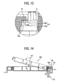
- An electrical connection box 100 disclosed in Patent Literature 2 and shown in Fig. 14 includes a body 102, and a cover 101 (that is, a mounting member), and a body-side hook 112 and a cover-side hook 111 are formed respectively at end portions of the body 102 and the cover 101.
- the cover-side hook 111 is inserted through an insertion port 120, and is engaged with the body-side hook 112, thereby forming a hinge mechanism 110.
- the cover-side hook 111 is inserted into the insertion port 120 in the body to thereby form the hinge mechanism 110, and the cover is pivotally moved about the hinge mechanism 110, and therefore the positioning of the cover and the body relative to each other for attaching purposes can be effected accurately.
- the insertion port 120 in the body is narrow, and besides there is provided no guide means for guiding the insertion of the cover-side hook 111, and therefore the insertion of the cover-side hook 111 is difficult, which has invited a problem that the efficiency of the operation is low.
- an object of this invention to provide an electrical connection box in which when assembling the electrical connection box, a body and a mounting member to be attached thereto can be accurately and easily positioned relative to each other, and an assembling method of the electrical connection box.
- an electrical connection box of the invention including:
- the mounting member includes a contact surface face-contacted with the mounting surface when the mounting member is attached to the body, and the shaft portion is provided far from the contact surface in a direction perpendicular to the contact surface.
- the limiting portion allows the inserting movement of the shaft portion in which the shaft portion is inserted into the receiving portion in a first inclining condition of the mounting member and limits the inserting movement of the shaft portion in a second inclining condition of the mounting member.
- an angle of the mounting member to the mounting surface is larger than a predetermined angle so that a distance between a top of the shaft portion and the mounting surface is smaller than the length of the insertion port.
- an angle of the mounting member to the mounting surface is smaller than or equal to a predetermined angle so that a distance between a top of the shaft portion and the mounting surface is longer than the length of the insertion port.
- the body includes a first printed circuit board having a first connector mounted thereon
- the mounting member includes a second printed circuit board having a second connector mounted thereon, and when the mounting member is attached to the body, the first connector is mated to the second connector to electrically connect the first printed circuit to the second printed circuit.
- the shaft portion has a reinforcing unit interposed between the shaft portion and the mounting member to reinforce the shaft portion.
- the mounting member is inclined in a condition in which an angle of the mounting member to the mounting surface is set to be larger than a predetermined angle.
- the body and the mounting member are connected together by the hinge formed by the shaft portion and the bearing portion, and the bearing portion has the insertion port through which the shaft portion, while sliding over the mounting surface toward the bearing portion, passes. Therefore, when assembling the electrical connection box, the shaft portion of the mounting member is slid over the mounting surface of the body toward the insertion port, and by doing so, the shaft portion can be inserted into the receiving portion through the insertion port. Therefore, the positioning for the purpose of passing the shaft portion through the insertion port can be easily effected, that is, the initial positioning of the body and the mounting member relative to each other can be easily effected, and therefore the efficiency of an operation for assembling the electrical connection box can be enhanced.
- the bearing portion includes the receiving portion for receiving the shaft portion passed through the insertion port, and the limiting portion for preventing the shaft portion from being disengaged from the receiving portion when the mounting member is pivotally moved. Therefore, even when the mounting member is pivotally moved about the hinge after the shaft portion is inserted into the receiving portion, the shaft portion is held in position by the limiting portion, and will not be disengaged from the receiving portion, so that the body and the mounting member are kept in their proper mounting positions, and therefore the efficiency of the operation for assembling the electrical connection box can be enhanced.
- the shaft portion is formed on the mounting member in such a manner that when the shaft portion is slid toward the bearing portion while the mounting member is kept inclined relative to the mounting surface at the angle smaller than or equal to the predetermined angle, the shaft portion is prevented from passing through the insertion port. Therefore, in order that the shaft portion can pass through the insertion port to be inserted into the bearing portion, the angle of inclination of the mounting member need to be larger than the above predetermined angle.
- the mounting member is inclined at such an angle that the shaft portion can pass through the insertion port to be inserted into the bearing portion, and by doing so, the angle of inclination of the mounting member is necessarily larger than the above predetermined angle, and parts mounted on and projecting from the opposed surfaces of the body and the mounting member are prevented from striking against each other. Therefore, damage of the parts due to an error during the assembling operation of the electrical connection box can be avoided, and therefore the operation for assembling the electrical connection box can be positively effected.
- the printed circuit board having the connector mounted thereon is received within the body, while the printed circuit board having the connector mounted thereon is received within the mounting member, and simultaneously when the mounting member is mounted on the mounting surface of the body in superposed relation thereto, the two connectors are fitted together. Therefore, simultaneously when the body and the mounting member are connected together by the hinge, and are positioned relative to each other for mounting purposes, the connectors are also positioned relative to each other. Therefore, simultaneously when the electrical connection box is assembled, the two connectors are fitted together. At this time, the two connectors are accurately fitted together without striking against each other and therefore without being damaged, and therefore the efficiency of the operation for assembling the electrical connection box can be enhanced.
- the shaft portion has the reinforcing unit which is interposed between the shaft portion and the mounting member to reinforce the shaft portion. Therefore, the strength of the shaft portion can be increased by the reinforcing unit, and therefore the strength of the hinge can be increased, and the assembled condition of the body and the mounting member can be more positively maintained.
- Fig. 1 is a perspective view showing one preferred embodiment of an electrical connection box of the present invention.
- Fig. 2 is a perspective view of the electrical connection box as seen from an angle different from that of Fig. 1 .
- Fig. 3 is a perspective view of the electrical connection box showing a condition in which shaft portions are inserted respectively in bearing portions.
- Fig. 4 is a top plan view of the electrical connection box as seen from an upper side of a mounting member, showing a condition in which the mounting member is attached to a body.
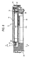
- Figs. 5 to 8 are cross-sectional views taken along the line X-X of Fig. 4 , showing a series of operations from the step of inserting the shaft portions into the respective bearing portions to the step of attaching the mounting member to the body.
- Figs. 1 is a perspective view showing one preferred embodiment of an electrical connection box of the present invention.
- Fig. 2 is a perspective view of the electrical connection box as seen from an angle different from that of Fig. 1 .
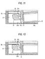
- FIG. 9 to 12 are enlarged views of a hinge portion of Figs. 5 to 8 .
- Fig. 13 is a cross-sectional view taken along the line Y-Y of Fig. 8 .
- Fig. 14 is a cross-sectional view of an important portion of a conventional electrical connection box.
- the electrical connection box 1 includes the body 20, and the mounting member 10 to be attached to the body 20.
- the mounting member 10 is an electronic control unit (also called an ECU which is an abbreviation of an Engine Control Unit or an Electronic Control Unit) of a vehicle.
- ECU Engine Control Unit
- this mounting member 10 is supplied with electric power from the body 2, and also controls electronic parts (such as relays and others) mounted within the body 20.
- the body 20 and the mounting member 10 are pivotally or rotatably and releasably connected together by the hinges 5 (see Fig. 3 ).
- the hinge 5 includes the shaft portion 19 formed on the mounting member 10, and the bearing portion 22 formed at the body 20.
- the mounting member 10 and the body 20, when connected together through the hinges 5, are positioned relative to each other, and therefore the electrical connection box can be properly assembled.
- the mounting member 10 includes a housing 11 made of an insulative synthetic resin, and a printed circuit board 15 (see Fig. 5 ).
- the housing 11 has a generally flattened box-like outer shape defined by six faces (or surfaces), that is, a contact surface 11A, an upper surface 11B and side surfaces 11a, 11b, 11c and 11d.
- the housing 11 has an internal space for receiving the printed circuit board 15 therein.
- the shaft portions 19 are formed on the side surface 11 a, and a lock claw 14 is formed on the side surface 11c facing away from the side surface 11a.
- the contact surface 11A is adapted to be contacted with (or abuts against) a mounting surface 21A of the body 20, and has a hole 11e (see Fig. 5 ) through which a connector mounted on the body 20 is passed when the contact surface 11A is held against the mounting surface 21A.
- the lock claw 14 is formed on a central portion of the side surface 11c, and projects downwardly ( Fig. 5 ). When the mounting member 10 and the body 20 are contacted with each other to be combined together, the lock claw 14 fits in a lock mechanism 24 provided at a housing 21 of the body 20, thereby fixing the mounting member 10 and the body 20 to each other.
- the shaft portion 19 is formed on and projects perpendicularly from the side surface 11a.
- the two (a pair of) shaft portions 19 are formed respectively at opposite end portions of the side surface 11a disposed adjacent respectively to the side surfaces 11 b and 11 d.
- the shaft portion 19 includes a support portion 12, and an engagement portion 13.
- the support portion 12 of each of the pair of shaft portions is formed by two walls, that is, a bottom wall 12a and a side wall 12b, and the two walls 12a and 12b extend perpendicularly from the side surface 11a.
- the bottom wall 12a is a flat plate-like wall disposed parallel to and above the contact surface 11A, and corresponds to reinforcing unit.
- the side wall 12b is connected integrally with the bottom wall 12a in intersecting relation thereto, and its outer surface is coplanar with the corresponding side surface 11b or 11d.
- the side wall 12b has a generally elliptic cross-section, and is gradually decreasing in size from its proximal end (disposed immediately adjacent to the side surface 11a) toward its distal end.
- the engagement portion 13 is formed at the distal end of the side wall 12b, and projects toward the other shaft portion 19, and the side wall 12b and the engagement portion 13 are formed integrally with and supported by the bottom wall 12a. Therefore, the bottom wall 12a serves to reinforce the shaft portion 19, so that the shaft portion 19 has an increased strength.
- any other suitable reinforcing unit may be provided in order to further increase the strength. For example, three or more walls may be provided, or the thickness of the wall may be increased.
- the engagement portion 13 of each of the pair of the shaft portions 19 includes a pillar portion 13a of a generally cylindrical shape, and a fixing claw 13b formed on the pillar portion 13a.
- the pair of pillar portions 13a are formed respectively at the distal ends of the side walls 12b of the support portions 12, and project toward each other in opposed relation, with their axes disposed parallel to the contact surface 11A. That end (lower end in Fig. 9 ) of the pillar portion 13a disposed close to the contact surface 11A is disposed on the upper side (see Fig. 9 ) of the bottom wall 12a, so that the pillar portion 13a projects upwardly from the bottom wall 12a.
- the fixing claw 13b has a triangular cross-section, and has a distal end edge (apex) directed upwardly.
- the fixing claw 13b is formed on the upper end (in Fig. 9 ) of the pillar portion 13 remote from the bottom wall 12a in parallel relation to the axis of the pillar portion 13.
- the fixing claw 13b is adapted to be bitingly engaged with fixing claws 22d (described later) of the bearing portion 22 to thereby fix the mounting member 10 and the body 20 to each other (see Figs. 12 and 13 ).
- the shaft portion 19 is formed by the support portion 12 and the engagement portion 13 as described above, the shaft portion 19 is not limited to this configuration, and may have any other suitable configuration in so far as it can be engaged with a projecting wall (corresponding to a limiting portion) of the bearing portion (described later).
- the shaft portion may have an engagement portion formed at a distal end of a support portion and projecting in a direction different from a direction of extending of this support portion.
- the bottom wall 12a is disposed at a level above the mating wall 11A, and the engagement portion 13 is formed on the upper side of the bottom wall 12a. Therefore, if the angle of the mounting member 10 relative to the mounting surface 21A is small when the engagement portions 13 are located on the mounting surface 21A, a corner portion 11f ( Fig. 10 ) formed by the contact surface 11A and the side surface 11a of the mounting member 10 abuts against the mounting surface 21A. Therefore, the engagement portion 13 is moved upwardly apart from the mounting surface 21A (see Figs. 10 and 11 ), so that the projecting wall 22c prevents the engagement portion 13 from passing through an insertion port 28 as described later.
- the inclined mounting member 10 is kept at an angle more than a certain angle.
- the pair of shaft portions 19 are so formed and disposed that the mounting member 10 can be kept at such an angle (a predetermined angle) that connectors 26 and 16 mounted respectively at the contact surfaces of the body 20 and the mounting member 10 will not interfere with each other.
- the shape and disposition of each shaft portion need to be suitably determined.
- the printed circuit board 15 is a well-known printed circuit board having a CPU (central processing unit) mounted thereon, the CPU controlling relays, etc., mounted on a printed circuit board 25 (described later) received within the body 20 as shown in Fig. 5 .
- the printed circuit board 15 is received within the housing 11 in parallel relation to the contact surface 11A, and is fixed to the housing 11 by screws or the like.
- the printed circuit board 15 has the connector 16 mounted thereon, and is connected to the printed circuit board 25 (described later) through this connector 16.
- the connector 16 includes a connector housing made of an insulative synthetic resin, and metal terminals received in this connector housing.
- the connector 16 is mounted on the printed circuit board 15, and extends perpendicularly therefrom toward the body 20, and is fitted to the connector 26 (mounted on the printed circuit board 25) through the hole 11e formed through the contact surface 11A.
- the body 20 includes the housing 21 made of an insulative synthetic resin, and the printed circuit board 25.
- the housing 21 has a generally flattened box-like outer shape, and has an internal space for receiving the printed circuit board 25 therein.
- the housing 21 includes the mounting surface 21A for the placing of the mounting member 10 thereon, side walls 21 a and 21 b and receiving walls 21 c and 21d extending upwardly from edge portions of the mounting surface 21A toward the mounting member 10, the lock mechanism 24, and the bearing portions 22.
- the mounting surface 21A is to be contacted with (that is, be held against) the contact surface 11A of the mounting member 10, and the side walls 21a and 21b and the receiving walls 21c and 21d extend upwardly from the edge portions of the contact surface 11A.
- the mounting member 10 is received in a region surrounded by these walls, and is attached to the mounting surface 21A.
- the mounting surface 21A has a hole 21e for enabling the connectors to be fitted together when attaching the mounting member 10 to the body 20.
- the side wall 21 b is disposed parallel to the direction (left-right direction in Fig. 4 ) of inserting of each shaft portion 19 into the corresponding bearing portion 22.
- the side surface 11 b of the mounting member 10 is slid along the side wall 21 b, and the shaft portions 19 are inserted respectively into the bearing portions 22, and by doing so, the mounting member 10 can be positioned relative to the body 2 in a direction (upward-downward direction in Fig. 4 ) perpendicular to the inserting direction.
- the side wall 21b is the wall extending upwardly from the mounting surface 21A
- the invention is not limited to this construction, and any other suitable guide portions can be used in so far as it has a guide function of positioning the mounting member 10 relative to the body 20 in the direction perpendicular to the direction of inserting of each shaft portion 19 into the bearing portion 22.
- the lock mechanism 24 is provided at the end (or edge) of the mounting surface 21A, and is disposed midway between the side wall 21 b and the receiving wall 21c.
- the lock mechanism 24 is fitted to the lock claw 14 of the mounting member 10, thereby combining and fixing the mounting member 10 and the body 20 together.
- the bearing portion 22 includes the insertion port 28, a receiving portion 27, side walls 22a and 22e, an upper wall 22b, and the projecting wall 22c.
- the insertion port 28 is an opening formed between a distal end of the projecting wall 22c (corresponding to the limiting portion) and the mounting surface 21A, and enables the shaft portion 19 to be inserted into the bearing portion 22 therethrough.
- the insertion port 28 is formed into a size slightly larger than the diameter of the pillar portion 13a. Part of a peripheral edge of the insertion port 28 is formed by the mounting surface 21A, and therefore the engagement portion 13 can be slid over the mounting surface 21A toward the bearing portion 22, and can pass through the insertion port 28.
- the insertion port 28 has the size slightly larger than the diameter of the pillar portion 13a, and also the engagement portion 13a is formed on the upper side of the bottom wall 12a disposed above the contact surface 11A. Therefore, when the mounting member 10 is pivotally moved toward the mounting surface 21A after each engagement portion 13 passes through the corresponding insertion port 28, the corner portion 11f (see Figs. 10 and 11 ) formed by the contact surface 11A and the side surface 11a of the mounting member 10 is brought into abutting engagement with the mounting surface 21A, and when this pivotal movement is further effected, each engagement portion 13 is moved upwardly apart from the mounting surface 21A.
- the receiving portion 27 is a region surrounded by the side walls 22a and 22e, the upper wall 22b, the projecting wall 22c and the mounting surface 21A, and this receiving portion 27 receives the shaft portion 19 inserted thereinto through the insertion port 28.
- the receiving portions 27 hold the respective shaft portions 19 in position, and hence the body 20 and the mounting member 10 are held in a mutually-positioned condition.
- the side walls 22a are formed upright respectively at the opposite ends of that side of the mounting surface 21A at which the side wall 21 a is formed, and extend upwardly from the mounting surface 21A, the side walls 22a being disposed in parallel relation to the side wall 21 a.
- the side wall 22e extends upwardly from the mounting surface 21A, and this side wall 22e perpendicularly intersects the side wall 22a in continuous relation thereto.
- the upper wall 22b is connected at its peripheral edge with a distal end of the side wall 22a and a distal end of the side wall 22e, and extends parallel to the mounting surface 21A in overlapping relation thereto.
- the two fixing claws 22d of a triangular cross-section are formed on an inner surface of the upper wall 22b, with their distal end edges directed toward the mounting surface 21A, the fixing claws 22d extending parallel to the direction of inserting of the shaft portion 19. These fixing claws 22d are bitingly engaged with the fixing claw 13b of the shaft portion 19, thereby fixing the mounting member 10 and the body 20 to each other (see Figs. 12 and 13 ).
- the projecting wall 22c (corresponding to the limiting portion) extends perpendicularly from a distal end of the upper wall 22b toward the mounting surface 21A, and is integrally connected at its one edge with the side wall 22e.
- the insertion port 28 for the passage of the engagement portion 13 (that is, the shaft portion 19) therethrough is formed between a distal end of the projecting wall 22c and the mounting surface 21A.
- the projecting wall 22c is coplanar with the side wall 21 a in continuous relation thereto.
- the projecting wall 22c is so shaped as to be retainingly engaged with the shaft portion 19 having the engagement portion 13 projecting upwardly relative to the mounting surface 21A.
- the projecting wall 22c that is, the limiting portion
- the limiting portion is not limited to this construction, and any other suitable limiting portion may be adopted in so far as it is disposed above the mounting surface, and can be engaged with the shaft portion inserted through the insertion port formed between the limiting portion and the mounting surface, and will not be disengaged from the shaft portion even when the shaft portion is pivotally moved.
- the projecting wall 22c is coplanar with the side wall 21 a in continuous relation thereto, the invention is not limited to this construction, and the positional relation of the projecting wall 22c (that is, the limiting portion) with other surfaces than the mounting surface is not of absolute necessity.
- the printed circuit board 25 is a well-known printed circuit board having relays and fuses mounted thereon. This printed circuit board 25 is received within the housing 21 in parallel relation to the mounting surface 21A, and is fixed to the housing 21 by screws or the like.
- the printed circuit board 25 has the connector 26 for connecting this printed circuit board to the printed circuit board 15.
- the connector 26 includes a connector housing made of an insulative synthetic resin, and metal terminals received within this connector housing.
- the connector 26 is mounted on the printed circuit board 25, and extends upwardly from the printed circuit board 25 toward the body 20, and is fitted to the connector 16 (mounted on the printed circuit board 15) through the hole 21e in the mounting surface 21A.
- the connectors 26 and 16 are so mounted respectively on the printed circuit boards 25 and 15 as to be accurately fitted together when the mounting member 10 is attached in a superposed manner to the mounting surface 21A of the body 20.
- the engagement portions 13 are located on the mounting surface 21A, with the mounting member 10 inclined relative to the mounting surface 21A of the body 20 at such an angle that the connectors 26 and 16 mounted respectively on the body 20 and the mounting member 10 will not interfere with each other, as shown in Fig. 5 .
- the positioning of the mounting member 10 in the upward-downward direction is effected.
- the corner portion 11f see Fig.
- each engagement portion 13 can be inserted into the bearing portion 22.
- the mounting member 10 while kept inclined at the above angle, is slid in a direction of arrow A with the engagement portions 13 kept in sliding contact with the mounting surface 21 a until the mounting member 10 is brought into abutting engagement with the side wall 21a.
- the engagement portions 13 slide over the mounting surface 21A, and also the side surface 11b of the mounting member 10 slides along the side wall 21b, and by doing so, in addition to the positioning in the upward-downward direction, the positioning in the direction from the rear side toward the front side can be effected.
- each engagement portion 13 passes through the insertion port 28, and is inserted into the receiving portion 27, and the engagement portion 13 (that is, the shaft portion 19) and the bearing portion 22 jointly form the hinge as shown in Fig. 6 .
- the mounting member 10 is pivotally moved toward the mounting surface 21A in a direction of arrow B about the hinges.
- the corner portion 11f see Fig. 10
- the corner portion 11f is brought into abutting engagement with the mounting surface 21A as shown in Fig. 7 .
- each engagement portion 13 interferes with the projecting wall 22c (that is, the limiting portion), and is retainingly engaged with this projecting wall 22c, and the movement of the mounting member 10 is limited such that the engagement portion 13 is located within the receiving portion 27.
- the positioning of the mounting member 10 for attaching purposes is effected, and thereafter the mounting member 10 will not be disengaged from the body 20.
- the positioning of the mounting member 10 for attaching purposes is thus effected, and therefore at the same time the positioning of the connectors 16 and 26 is effected.
- the connectors 16 and 26 are fitted together as shown in Fig. 8 , and the metal terminals within the connector 16 are contacted respectively with the metal terminals within the connector 26, so that the printed circuit boards 15 and 25 are electrically connected together. Also, the lock claw 14 and the lock mechanism 24 are fitted together, so that the mounting member 10 and the body 20 are fixed to each other at their one ends.
- each engagement portion 13 and the fixing claws 22d of the corresponding bearing portion 22 are bitingly engaged with each other, and the engagement portion 13 is urged by the bearing portion 22 toward the mounting surface 21A, so that the mounting member 10 and the body 20 are fixed to each other at the other ends thereof, thus assembling the electrical connection box 1.
- the body 20 and the mounting member 10 are connected together by the hinges 5 each formed by the shaft portion 19 and the bearing portion 22, and the bearing portion 22 has the insertion port 28 through which the shaft portion 19, while sliding over the mounting surface 21A toward the bearing portion 22, passes. Therefore, when assembling the electrical connection box 1, the shaft portions 19 of the mounting member 10 are held in contact with the mounting surface 21A of the body 20, and in this condition each shaft portion 19 is slid toward the insertion port 28, and by doing so, the shaft portion 19 can be inserted into the receiving portion 27 through the insertion port 28.
- the bearing portion 22 includes the receiving portion 27 for receiving the shaft portion 19 passed through the insertion port 28, and the projecting wall 22c (that is, the limiting portion) for preventing the shaft portion 19 from being disengaged from the receiving portion 27 when the mounting member 10 is pivotally moved.
- each shaft portion 19 is held in position by the projecting wall 22c, and will not be disengaged from the receiving portion 27, so that the body 20 and the mounting member 10 are kept in their proper mounting positions, and therefore the efficiency of the operation for assembling the electrical connection box 1 can be enhanced.
- each engagement portion 13 is formed on the mounting member 10 in such a manner that when each engagement portion 13 is slid toward the bearing portion 22 while the mounting member 10 is kept inclined relative to the mounting surface 21A at an angle smaller than the predetermined angle at which the connectors 26 and 16 will not interfere with each other, the engagement portion 13 is prevented from passing through the insertion port 28. Therefore, in order that the engagement portion 13 can pass through the insertion port 28 to be inserted into the bearing portion 22, the angle of inclination of the mounting member 10 need to be not smaller than the above predetermined angle.
- the mounting member 10 is inclined at such an angle that the engagement portion 13 can pass through the insertion port 28 to be inserted into the bearing portion 22, and by doing so, the angle of inclination of the mounting member 10 is necessarily not smaller than the above predetermined angle, and the connectors 26 and 16 mounted respectively at the opposed surfaces of the body 20 and the mounting member 10 can be prevented from striking against each other. Therefore, damage of the connectors 26 and 16 due to an error during the assembling operation of the electrical connection box can be avoided, and therefore the operation for assembling the electrical connection box 1 can be positively effected.
- the printed circuit board 25 having the connector 26 mounted thereon is received within the body 20, while the printed circuit board 15 having the connector 16 mounted thereon is received within the mounting member 10, and simultaneously when the mounting member 10 is mounted on the mounting surface 21A of the body 20 in superposed relation thereto, the two connectors 26 and 16 are fitted together. Therefore, simultaneously when the body 20 and the mounting member 10 are connected together by the hinges, and are positioned relative to each other for mounting purposes, the connectors 26 and 16 are also positioned relative to each other. Therefore, simultaneously when the electrical connection box 1 is assembled, the two connectors 26 and 16 are fitted together. At this time, the two connectors 26 and 16 are accurately fitted together without striking against each other and therefore without being damaged, and therefore the efficiency of the operation for assembling the electrical connection box 1 can be enhanced.
- the body 20 has the side wall 21 b serving as the guide portion for abutting against the mounting member 10 so as to guide the same toward the insertion ports 28. Therefore, when assembling the electrical connection box 1, the mounting member 10 is held in contact with both of the mounting surface 21A and the side wall 21b of the body 20, and in this condition the mounting member 10 is slid toward the insertion ports 28, and by doing so, the positioning of the mounting member 10 for passing the engagement portions 13 through the respective insertion ports 28 can be effected in the plurality of directions, and therefore the efficiency of the operation for assembling the electrical connection box 1 can be further enhanced.
- the shaft portion 19 includes the support portion 12 having the two walls (that is, the bottom wall 12a and the side wall 12b extending perpendicularly from the mounting member 10), and therefore the bottom wall 12a serves as the reinforcing unit for supporting the side wall 12b and the engagement portion 13, and can increase the strength of the shaft portion 19. Therefore, the strength of each hinge 5 can be increased, and the assembled condition of the body 20 and the mounting member 10 can be more positively maintained.
- the invention is not limited to such electrical connection box, but can be applied to any other suitable structural assembling unit in which a box-like member is mounted on a member having a mounting surface.
Landscapes
- Connection Or Junction Boxes (AREA)
- Casings For Electric Apparatus (AREA)
Applications Claiming Priority (1)
| Application Number | Priority Date | Filing Date | Title |
|---|---|---|---|
| JP2007002378A JP5088811B2 (ja) | 2007-01-10 | 2007-01-10 | 電気接続箱 |
Publications (3)
| Publication Number | Publication Date |
|---|---|
| EP1944836A2 true EP1944836A2 (fr) | 2008-07-16 |
| EP1944836A3 EP1944836A3 (fr) | 2012-12-05 |
| EP1944836B1 EP1944836B1 (fr) | 2014-04-23 |
Family
ID=39276062
Family Applications (1)
| Application Number | Title | Priority Date | Filing Date |
|---|---|---|---|
| EP08000310.6A Active EP1944836B1 (fr) | 2007-01-10 | 2008-01-09 | Boîtier de connexion électrique et procédé d'assemblage de la boîte de connexion électrique |
Country Status (5)
| Country | Link |
|---|---|
| US (1) | US7507094B2 (fr) |
| EP (1) | EP1944836B1 (fr) |
| JP (1) | JP5088811B2 (fr) |
| CN (1) | CN101222127B (fr) |
| AU (1) | AU2008200111B2 (fr) |
Cited By (1)
| Publication number | Priority date | Publication date | Assignee | Title |
|---|---|---|---|---|
| EP3534473A1 (fr) * | 2018-03-02 | 2019-09-04 | GIRA GIERSIEPEN GmbH & Co. KG | Appareil d'installation électronique de la technique des systèmes de bâtiments |
Families Citing this family (25)
| Publication number | Priority date | Publication date | Assignee | Title |
|---|---|---|---|---|
| US7718892B2 (en) * | 2007-04-06 | 2010-05-18 | Flextronics Automotive Inc. | Control module housing |
| DE102008052912A1 (de) * | 2008-10-23 | 2010-05-06 | Abb Technology Ag | Feldgerät, insbesondere Durchflussmessgerät |
| JP5272836B2 (ja) * | 2009-03-23 | 2013-08-28 | 株式会社デンソー | 電子接続箱と電子制御装置との組付け構造、それに用いられる電子制御装置および電子接続箱 |
| JP2012022973A (ja) * | 2010-07-16 | 2012-02-02 | Yazaki Corp | 電線の圧接接続構造 |
| JP5666924B2 (ja) * | 2011-01-18 | 2015-02-12 | 古河電気工業株式会社 | 車両用の電気接続箱 |
| JP5798781B2 (ja) * | 2011-01-28 | 2015-10-21 | 矢崎総業株式会社 | 電気接続箱 |
| JP5704350B2 (ja) | 2012-06-20 | 2015-04-22 | 住友電装株式会社 | 電気接続箱 |
| US8723035B2 (en) * | 2012-08-31 | 2014-05-13 | Flextronics Ap, Llc | Vibration reduction rib |
| JP5900839B2 (ja) | 2012-10-09 | 2016-04-06 | 住友電装株式会社 | 電気接続箱 |
| JP5999638B2 (ja) * | 2012-11-12 | 2016-09-28 | 矢崎総業株式会社 | 電子ユニット取付構造 |
| JP2014121148A (ja) * | 2012-12-14 | 2014-06-30 | Toshiba Corp | 車両用電力変換装置及び鉄道車両 |
| JP5958831B2 (ja) * | 2013-03-27 | 2016-08-02 | 住友電装株式会社 | 電気接続箱 |
| CN203250925U (zh) * | 2013-05-03 | 2013-10-23 | 泰科电子(上海)有限公司 | 连接器插头和连接器组件 |
| JP6281707B2 (ja) | 2014-10-23 | 2018-02-21 | 住友電装株式会社 | 電気接続箱 |
| JP6277109B2 (ja) * | 2014-11-14 | 2018-02-07 | 住友電装株式会社 | 電気接続箱 |
| CN106151817B (zh) * | 2015-03-25 | 2017-12-08 | 赛尔富电子有限公司 | 一种安装装置及其组装、拆卸方法 |
| DE102016201426A1 (de) * | 2016-01-29 | 2017-08-03 | Eaton Protection Systems Ip Gmbh & Co. Kg | Kasten mit Gelenkeinrichtung |
| WO2017179650A1 (fr) * | 2016-04-14 | 2017-10-19 | 株式会社オートネットワーク技術研究所 | Dispositif de stockage d'énergie |
| WO2018051892A1 (fr) * | 2016-09-14 | 2018-03-22 | 住友電装株式会社 | Boîte de jonction électrique |
| JP6836889B2 (ja) * | 2016-12-06 | 2021-03-03 | 矢崎総業株式会社 | 電気接続箱、及び、ワイヤハーネス |
| JP6798409B2 (ja) * | 2017-04-28 | 2020-12-09 | 住友電装株式会社 | 電池配線モジュール |
| CN107887193A (zh) * | 2017-12-12 | 2018-04-06 | 无锡优耐特能源科技有限公司 | 一种多地控制紧急停止和多地启动控制开关的安装架 |
| JP7068252B2 (ja) * | 2019-09-30 | 2022-05-16 | 矢崎総業株式会社 | 電気接続箱ユニット |
| US11623590B2 (en) | 2021-01-08 | 2023-04-11 | Lear Corporation | Electrical connector cover |
| US11855429B2 (en) * | 2021-07-29 | 2023-12-26 | Sumitomo Wiring Systems, Ltd. | Electric junction box assembly with removable cover |
Citations (2)
| Publication number | Priority date | Publication date | Assignee | Title |
|---|---|---|---|---|
| JPH09163552A (ja) | 1995-12-07 | 1997-06-20 | Yazaki Corp | 電気接続箱 |
| JP2003009347A (ja) | 2001-06-20 | 2003-01-10 | Sumitomo Wiring Syst Ltd | 電気接続箱 |
Family Cites Families (17)
| Publication number | Priority date | Publication date | Assignee | Title |
|---|---|---|---|---|
| GB442364A (en) * | 1935-05-30 | 1936-02-07 | Callenders Cable & Const Co | Improvements relating to hinged connections |
| JP3779742B2 (ja) * | 1994-10-14 | 2006-05-31 | 三甲株式会社 | 缶状物品収納ケース |
| JP3351499B2 (ja) * | 1996-06-24 | 2002-11-25 | 矢崎総業株式会社 | コネクタ装置 |
| US6683950B1 (en) * | 1997-06-25 | 2004-01-27 | Charles Industries, Ltd. | Cover for a remote terminal |
| JP2001057723A (ja) * | 1999-08-10 | 2001-02-27 | Yazaki Corp | 電気接続箱への電子ユニット取付構造 |
| JP3365365B2 (ja) | 1999-09-02 | 2003-01-08 | 住友電装株式会社 | 電気接続箱の取付構造 |
| JP3985570B2 (ja) * | 2002-04-08 | 2007-10-03 | 住友電装株式会社 | 電気接続箱 |
| JP3948657B2 (ja) * | 2002-07-16 | 2007-07-25 | 矢崎総業株式会社 | 電気接続箱 |
| JP4064766B2 (ja) * | 2002-08-30 | 2008-03-19 | 矢崎総業株式会社 | 電気接続箱 |
| JP2005176539A (ja) | 2003-12-12 | 2005-06-30 | Yazaki Corp | 箱体の固定構造 |
| KR100516513B1 (ko) * | 2004-02-19 | 2005-09-26 | 타이코에이엠피 주식회사 | 차량용 정션박스 및 그 조립방법 |
| JP4342433B2 (ja) | 2004-12-24 | 2009-10-14 | 矢崎総業株式会社 | ジャンクションボックス |
| JP4408826B2 (ja) * | 2005-03-23 | 2010-02-03 | 矢崎総業株式会社 | 電気回路基板収容箱 |
| JP4475160B2 (ja) * | 2005-04-13 | 2010-06-09 | 株式会社デンソー | 電子装置の製造方法 |
| JP4832263B2 (ja) * | 2006-11-16 | 2011-12-07 | 株式会社オートネットワーク技術研究所 | 電気接続箱 |
| US7616438B2 (en) * | 2006-11-21 | 2009-11-10 | Autonetworks Technologies, Ltd. | Electric connection box |
| JP4835451B2 (ja) * | 2007-02-01 | 2011-12-14 | 住友電装株式会社 | 自動車用の電気接続箱 |
-
2007
- 2007-01-10 JP JP2007002378A patent/JP5088811B2/ja active Active
-
2008
- 2008-01-08 US US11/970,927 patent/US7507094B2/en active Active
- 2008-01-09 AU AU2008200111A patent/AU2008200111B2/en active Active
- 2008-01-09 EP EP08000310.6A patent/EP1944836B1/fr active Active
- 2008-01-10 CN CN2008100004488A patent/CN101222127B/zh active Active
Patent Citations (2)
| Publication number | Priority date | Publication date | Assignee | Title |
|---|---|---|---|---|
| JPH09163552A (ja) | 1995-12-07 | 1997-06-20 | Yazaki Corp | 電気接続箱 |
| JP2003009347A (ja) | 2001-06-20 | 2003-01-10 | Sumitomo Wiring Syst Ltd | 電気接続箱 |
Cited By (1)
| Publication number | Priority date | Publication date | Assignee | Title |
|---|---|---|---|---|
| EP3534473A1 (fr) * | 2018-03-02 | 2019-09-04 | GIRA GIERSIEPEN GmbH & Co. KG | Appareil d'installation électronique de la technique des systèmes de bâtiments |
Also Published As
| Publication number | Publication date |
|---|---|
| JP5088811B2 (ja) | 2012-12-05 |
| CN101222127A (zh) | 2008-07-16 |
| CN101222127B (zh) | 2010-08-04 |
| JP2008172889A (ja) | 2008-07-24 |
| US20080166909A1 (en) | 2008-07-10 |
| AU2008200111A1 (en) | 2008-07-24 |
| EP1944836A3 (fr) | 2012-12-05 |
| EP1944836B1 (fr) | 2014-04-23 |
| AU2008200111B2 (en) | 2011-02-17 |
| US7507094B2 (en) | 2009-03-24 |
Similar Documents
| Publication | Publication Date | Title |
|---|---|---|
| EP1944836B1 (fr) | Boîtier de connexion électrique et procédé d'assemblage de la boîte de connexion électrique | |
| US7777132B2 (en) | Electrical connection box | |
| EP1936749B1 (fr) | Organe de contact, connecteur et procédé de fabrication | |
| EP1944835B1 (fr) | Boîtier de connexion électrique | |
| EP3208893B1 (fr) | Connecteur avec assurance de position de borne | |
| US6364681B1 (en) | Connector assembly and method of mounting same | |
| EP0889559B1 (fr) | Méthode de fabrication d'un connecteur pour carte imprimée | |
| JP4577209B2 (ja) | コネクタ | |
| JP2007537566A (ja) | プラグコネクタ及び該プラグコネクタのプレアセンブリ方法 | |
| EP1882286B1 (fr) | Connecteur electrique | |
| JP2001155810A (ja) | コネクタ | |
| JP4990635B2 (ja) | 電気接続箱 | |
| US7775815B2 (en) | LIF connector | |
| JPH11312551A (ja) | コネクタの接続構造 | |
| JP2001319712A (ja) | コネクタ及びコネクタと回路基板の接続構造 | |
| US20010039147A1 (en) | Assembling structure of electronic unit to electrical connecting box | |
| JPH11176517A (ja) | 組み合わせコネクタ及び組み合わせコネクタとケーシングとの結合構造 | |
| JP6574453B2 (ja) | コネクタユニット | |
| JP4091497B2 (ja) | 電気接続箱とその組立方法 | |
| JP2000294321A (ja) | コネクタの装着構造 | |
| JP3980944B2 (ja) | 接続装置 | |
| JPH10321291A (ja) | コネクタの取付構造 | |
| CN115714278A (zh) | 壳体与连接器的嵌合构造 | |
| JP3178339B2 (ja) | 端子挿入補助具およびその補助具を含むコネクタ保持具 | |
| EP3316412A1 (fr) | Connecteur destiné à connecter un câble électrique à une carte |
Legal Events
| Date | Code | Title | Description |
|---|---|---|---|
| PUAI | Public reference made under article 153(3) epc to a published international application that has entered the european phase |
Free format text: ORIGINAL CODE: 0009012 |
|
| AK | Designated contracting states |
Kind code of ref document: A2 Designated state(s): AT BE BG CH CY CZ DE DK EE ES FI FR GB GR HR HU IE IS IT LI LT LU LV MC MT NL NO PL PT RO SE SI SK TR |
|
| AX | Request for extension of the european patent |
Extension state: AL BA MK RS |
|
| PUAL | Search report despatched |
Free format text: ORIGINAL CODE: 0009013 |
|
| AK | Designated contracting states |
Kind code of ref document: A3 Designated state(s): AT BE BG CH CY CZ DE DK EE ES FI FR GB GR HR HU IE IS IT LI LT LU LV MC MT NL NO PL PT RO SE SI SK TR |
|
| AX | Request for extension of the european patent |
Extension state: AL BA MK RS |
|
| RIC1 | Information provided on ipc code assigned before grant |
Ipc: H01R 13/627 20060101AFI20121029BHEP Ipc: H01R 13/631 20060101ALI20121029BHEP |
|
| 17P | Request for examination filed |
Effective date: 20130415 |
|
| AKX | Designation fees paid |
Designated state(s): DE FR GB |
|
| GRAP | Despatch of communication of intention to grant a patent |
Free format text: ORIGINAL CODE: EPIDOSNIGR1 |
|
| INTG | Intention to grant announced |
Effective date: 20131114 |
|
| GRAS | Grant fee paid |
Free format text: ORIGINAL CODE: EPIDOSNIGR3 |
|
| GRAA | (expected) grant |
Free format text: ORIGINAL CODE: 0009210 |
|
| AK | Designated contracting states |
Kind code of ref document: B1 Designated state(s): DE FR GB |
|
| REG | Reference to a national code |
Ref country code: GB Ref legal event code: FG4D |
|
| REG | Reference to a national code |
Ref country code: DE Ref legal event code: R096 Ref document number: 602008031638 Country of ref document: DE Effective date: 20140605 |
|
| REG | Reference to a national code |
Ref country code: DE Ref legal event code: R097 Ref document number: 602008031638 Country of ref document: DE |
|
| PLBE | No opposition filed within time limit |
Free format text: ORIGINAL CODE: 0009261 |
|
| STAA | Information on the status of an ep patent application or granted ep patent |
Free format text: STATUS: NO OPPOSITION FILED WITHIN TIME LIMIT |
|
| 26N | No opposition filed |
Effective date: 20150126 |
|
| REG | Reference to a national code |
Ref country code: DE Ref legal event code: R097 Ref document number: 602008031638 Country of ref document: DE Effective date: 20150126 |
|
| REG | Reference to a national code |
Ref country code: FR Ref legal event code: PLFP Year of fee payment: 9 |
|
| REG | Reference to a national code |
Ref country code: FR Ref legal event code: PLFP Year of fee payment: 10 |
|
| REG | Reference to a national code |
Ref country code: FR Ref legal event code: PLFP Year of fee payment: 11 |
|
| PGFP | Annual fee paid to national office [announced via postgrant information from national office to epo] |
Ref country code: GB Payment date: 20231130 Year of fee payment: 17 |
|
| PGFP | Annual fee paid to national office [announced via postgrant information from national office to epo] |
Ref country code: FR Payment date: 20231212 Year of fee payment: 17 |
|
| PGFP | Annual fee paid to national office [announced via postgrant information from national office to epo] |
Ref country code: DE Payment date: 20231128 Year of fee payment: 17 |