EP1944835B1 - Boîtier de connexion électrique - Google Patents
Boîtier de connexion électrique Download PDFInfo
- Publication number
- EP1944835B1 EP1944835B1 EP08000306.4A EP08000306A EP1944835B1 EP 1944835 B1 EP1944835 B1 EP 1944835B1 EP 08000306 A EP08000306 A EP 08000306A EP 1944835 B1 EP1944835 B1 EP 1944835B1
- Authority
- EP
- European Patent Office
- Prior art keywords
- arm
- mounting member
- electrical connection
- lock
- connection box
- Prior art date
- Legal status (The legal status is an assumption and is not a legal conclusion. Google has not performed a legal analysis and makes no representation as to the accuracy of the status listed.)
- Active
Links
- 238000010276 construction Methods 0.000 description 6
- 238000013461 design Methods 0.000 description 3
- 238000003780 insertion Methods 0.000 description 3
- 230000037431 insertion Effects 0.000 description 3
- 238000011161 development Methods 0.000 description 2
- 229920003002 synthetic resin Polymers 0.000 description 2
- 239000000057 synthetic resin Substances 0.000 description 2
- 230000003247 decreasing effect Effects 0.000 description 1
- 230000000994 depressogenic effect Effects 0.000 description 1
- 230000002708 enhancing effect Effects 0.000 description 1
- 238000012423 maintenance Methods 0.000 description 1
- 230000007257 malfunction Effects 0.000 description 1
- 238000000034 method Methods 0.000 description 1
Images


Classifications
-
- H—ELECTRICITY
- H01—ELECTRIC ELEMENTS
- H01R—ELECTRICALLY-CONDUCTIVE CONNECTIONS; STRUCTURAL ASSOCIATIONS OF A PLURALITY OF MUTUALLY-INSULATED ELECTRICAL CONNECTING ELEMENTS; COUPLING DEVICES; CURRENT COLLECTORS
- H01R13/00—Details of coupling devices of the kinds covered by groups H01R12/70 or H01R24/00 - H01R33/00
- H01R13/62—Means for facilitating engagement or disengagement of coupling parts or for holding them in engagement
- H01R13/627—Snap or like fastening
- H01R13/6271—Latching means integral with the housing
-
- H—ELECTRICITY
- H01—ELECTRIC ELEMENTS
- H01R—ELECTRICALLY-CONDUCTIVE CONNECTIONS; STRUCTURAL ASSOCIATIONS OF A PLURALITY OF MUTUALLY-INSULATED ELECTRICAL CONNECTING ELEMENTS; COUPLING DEVICES; CURRENT COLLECTORS
- H01R12/00—Structural associations of a plurality of mutually-insulated electrical connecting elements, specially adapted for printed circuits, e.g. printed circuit boards [PCB], flat or ribbon cables, or like generally planar structures, e.g. terminal strips, terminal blocks; Coupling devices specially adapted for printed circuits, flat or ribbon cables, or like generally planar structures; Terminals specially adapted for contact with, or insertion into, printed circuits, flat or ribbon cables, or like generally planar structures
- H01R12/70—Coupling devices
- H01R12/71—Coupling devices for rigid printing circuits or like structures
Definitions
- This invention relates to an electrical connection box to be mounted on a vehicle or the like, and more particularly to an electrical connection box in which a body and a mounting member to be mounted on the body are releasably connected together through a hinge.
- An electrical connection box also called a junction block
- a body including a housing having a plurality of electronic parts (such for example as fuses, relays, etc.) received therein, and an electronic control unit (ECU) (serving as a mounting member) having a control circuit for controlling the plurality of electronic parts.
- ECU electronice control unit
- the above electrical connection box is constructed such that the electronic control unit is incorporated in the housing of the body (see, for example, Patent Literature 1).
- Patent Literature 1 In recent years, however, in order to enhance the efficiency of maintenance in the event of a malfunction of the control circuit or the electronic control unit and also to reduce the cost required for exchanging parts, there have been used electrical connection boxes of the type in which an electronic control unit having a control circuit received in a housing separate from a housing of a body is fixedly attached to the body by fixing means such as a lock, a hinge, screws or others (see, for example, Patent Literature 2).
- the electronic control unit and the body are fixed to each other by a hinge and locks so that the former can be easily attached to the body with less time and labor.
- This hinge includes a hook formed at one end of the electronic control unit, and a hook receiving recess which is formed at one end of the body such that the hook can be rotatably and releasably received in this hook receiving recess.
- the lock includes a lock arm formed at the other end of the electronic control unit, and a lock arm insertion hole which is formed in the other end of the body such that the lock arm can be engaged in this lock arm insertion hole.
- the hook is engaged in the hook receiving recess, and then the electronic control unit is rotatably moved toward the body about the hook, so that the lock arm is engaged in the lock arm insertion hole, thereby fixing the electronic control unit to the body.
- the above problem of the shaking movement can be dealt with, for example, by fixing the electronic control unit and the body together by screws after the former is attached to the latter. In this case, however, there arises another problem that the number of component parts increases, and besides the operation for mounting the electronic control unit on the body becomes cumbersome.
- an electrical connection box of the invention which includes a body; a mounting member attached to the body; a lock arm which is provided at one of the body and the mounting member, the lock arm including:
- one of the first engaging portion and the second engaging portion has a through hole, and the other of the first engaging portion and the second engaging portion has a convex shape.
- one of the first engaging portion and the second engaging portion has a concave shape, and the other of the first engaging portion and the second engaging portion has a convex shape.
- a plurality of the projections are provided so as to hold the arm portion therebetween.
- a plurality of the projections are provided in such a manner that the projections are spaced to each other along the surface of the receiving portion.
- a clearance is formed between an outer wall providing the lock arm and an outer wall providing the lock receiving portion.
- the body and the mounting member are rotatably connected together at their one ends through a hinge, and the lock arm and the lock receiving portion are provided at the other ends of the body and the mounting member.
- the body includes a first board having a first connector
- the mounting member includes a second board having a second connector and when the mounting member is attached to the body, the first connector is fitted to the second connector so that the first board is electrically connected to the second board.
- the engaging portion is formed on that portion of the inner surface of the receiving portion disposed deeper than the lock projection in the direction of inserting of the arm portion into the receiving portion, and abuts against the arm portion to locate the lock arm in the predetermined position thereof, thereby locating the mounting member in the predetermined position thereof relative to the body. Therefore, even when a clearance is formed between the mounting member and the body, the mounting member can be located in the predetermined position relative to the body merely by engaging the lock arm with the lock receiving portion without fixing the mounting member and the body to each other by screws or the like. Therefore, there can be provided the electrical connection box in which the mounting member can be easily attached to the body, and also a relative shaking movement between the mounting member and the body can be prevented from developing after the mounting member is attached to the body.
- the engaging portion shaped in a convex or concave, or having a through hole is formed on that portion of the inner surface of the tubular portion disposed deeper than the projection receiving portion in the direction of inserting of the arm portion into the tubular portion, and abuts against the arm portion to locate the lock arm in the predetermined position thereof, thereby locating the mounting member in the predetermined position thereof relative to the body. Therefore, even when a clearance is formed between the mounting member and the body, the mounting member can be located in the predetermined position relative to the body merely by engaging the lock arm with the lock receiving portion without fixing the mounting member and the body to each other by screws or the like. Therefore, there can be provided the electrical connection box in which the mounting member can be easily attached to the body, and also a relative shaking movement between the mounting member and the body can be prevented from developing after the mounting member is attached to the body.
- the plurality of projecting portions are provided so as to hold the arm portion therebetween. Therefore, the arm portion can be located in a generally central region of the receiving portion in a direction of opposing of the projecting portions to each other, and therefore the arm portion can be positioned with a smaller amount of movement of the arm portion as compared with the case where the arm portion is positioned by causing a projecting portion to abut against only one side (or surface) of the arm portion such that the arm portion abuts against that portion of the inner surface of the receiving portion opposed to this projecting portion. Therefore, the mounting member can be more smoothly attached to the body.
- the projecting portions are formed on and along the inner surface of the receiving portion, and are spaced from each other. Therefore, the area of contact of these projecting portions with the arm portion can be reduced, and a frictional resistance can be reduced, and therefore the arm portion can be located in the predetermined position within the receiving portion with a smaller force. And besides, a lightweight design of the electrical connection box can be achieved.
- the clearance is formed between the outer wall having the lock arm formed thereon and the outer wall having the lock receiving portion formed thereon. Therefore, the mounting member can be smoothly attached to the body without being caught thereon, and therefore the mounting member can be more easily attached to the body
- the body and the mounting member are pivotally connected together at their one ends through the hinge, and the fixing portion is provided at the other ends of the body and the mounting member. Therefore, the mounting member can be quite easily attached to the body without effecting a precise positioning. Furthermore, the mounting member, while pivotally moved about the hinge, is attached to the body, and with this construction a larger clearance must be formed between the mounting member and the body as compared with the case where the mounting member is moved linearly toward the body, and is attached thereto.
- the board having the connector mounted thereof is mounted within the body and the board having the connector mounted thereon is mounted within the mounting member, and when the mounting member is attached to the body, the connectors are fitted to each other, so that the boards are electrically connected together.
- this electrical connection box a relative shaking movement between the mounting member and the body can be prevented, and therefore wear of terminals of the connectors can be prevented, and also the reliability of connection between the terminals and hence the reliability of connection between the boards can be secured.
- the electrical connection box 1 of this embodiment is fixed to a panel forming a vehicle body of an automobile or other portion of the automobile, and various electronic equipments mounted on the automobile are electrically connected together in a predetermined pattern through this electrical connection box 1.
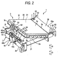
- the electrical connection box 1 includes a body 2, and an electronic control unit (hereinafter referred to as "ECU” which is an abbreviation of Engine Control Unit) 3 serving as a mounting member to be attached to the body 2, hinges 8 rotatably and releasably connecting the body 2 and the ECU 3 together, a fixing portion 9 for fixing the body 2 and the ECU 3 to each other.
- ECU electronice control unit
- the body 2 includes a housing 20 made of an insulative synthetic resin, and a printed circuit board 21 (see Figs. 6 to 8 ) mounted on the housing 20.
- the housing 20 includes a mounting surface portion 2a in the form of a square plate, a block-like interconnecting portion 26 formed integrally at one end of the mounting surface portion 2a (that is, one outer edge of the mounting surface portion 2a), an upstanding wall 2c formed on and extending downwardly ( Fig. 1 ) from the other end of the mounting surface portion 2a (that is, that outer edge of the mounting surface portion 2a remote from the interconnecting block 26), an upstanding portion 46 continuous with the upstanding wall 2c and extending upwardly ( Fig. 1 ) from the mounting surface portion 2a, and a guide wall 2f formed on and extending upwardly from that outer edge of the mounting surface portion 2a lying between the interconnecting portion 26 and the upstanding wall 2c.
- the connecting portion 26 includes a surface 26e extending in a direction perpendicular to the mounting surface portion 2a and intersecting the one end of the mounting surface portion 2a, and a surface 26a extending from that end of the surface 26e disposed above the mounting surface portion 2a (in Fig. 1 ) in a direction parallel to the mounting surface portion 2a.
- the upstanding portion 46 is in the form of a square plate, and provided in a direction perpendicular to the mounting surface portion 2a.
- the guide wall 2f extends upwardly (in Fig. 1 ) from the outer edge of the mounting surface portion 2a, that is, in a direction perpendicular to the mounting surface portion 2a.
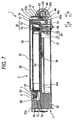
- the printed circuit board 21 is a well-known printed circuit board having relays and fuses mounted thereon. As shown in Figs. 5 to 7 , this printed circuit board 21 is disposed under the mounting surface portion 2a (in Fig. 6 ) in parallel to the mounting surface portion 2a. The printed circuit board 21 has a connector 24 for electrically connecting this printed circuit board 21 to a printed circuit board 31 (described later) of the ECU 3.
- the connector 24 includes bar-like male terminals 22 which are connected to a circuit pattern formed on the printed circuit board 21 and extend upwardly toward the mounting surface portion 2a, and a synthetic resin-made connector housing 23 of a tubular shape surrounding the plurality of the male terminals 22.
- This connector 24 passes through a through hole formed through the mounting surface portion 2a such that part of the connector 24 projects upwardly (in Fig. 5 ) beyond the mounting surface portion 2a.
- the ECU 3 includes a housing 30 made of an insulative synthetic resin, and the printed circuit board 31 (see Figs. 5 to 7 ) received within the housing 30.
- the housing 30 includes an upper wall 3a in the form of a square plate generally identical in shape to the mounting surface portion 2a, side walls 3c, 3d, 3e and 3f extending perpendicularly respectively from four side (or outer) edges of the upper wall 3a, and a lower wall 3b disposed in opposed, spaced relation to the upper wall 3a and integrally connected to lower edges of the side walls 3c, 3d, 3e and 3f remote from the upper wall 3a.
- this housing 30 has a flat plate-like outer shape, and has an internal space for receiving the printed circuit board 31 therein.
- the housing 30 is attached to the body 2 in such a manner that the lower wall 3b abuts against the mounting surface portion 2a and that the side wall 3f abuts against the guide wall 2f (see Figs. 3 and 4 ). Namely, the housing 30 is received in a frame-like space formed by the surface 26e, the guide wall 2f and the upstanding portion 46. A dimension of the housing 30 from an outer surface of the side wall 3c to an outer surface of the side wall 3e is slightly smaller than a dimension of the housing 20 from the upstanding portion 46 to the surface 26e.
- the printed circuit board 31 is a well-known printed circuit board having a control circuit for controlling the relays and fuses mounted on the printed circuit board 21 of the body 2. As shown in Figs. 5 to 7 , the printed circuit board 31 is received within the housing 30 in parallel relation to the upper wall 3a and the lower wall 3b. The printed circuit board 31 has a connector 34 for electrically connecting this printed circuit board 31 to the printed circuit board 21 of the body 2.
- the connector 34 includes tubular female terminals 32 which are connected to a circuit pattern formed on the printed circuit board 31 and extend downwardly toward the lower wall 3b, and a synthetic resin-made connector housing 33 of a tubular shape receiving the female terminals 32.
- a through hole is formed through that portion of the lower wall 3b corresponding to the connector 34, and the connector 24 of the body 2 is fitted to the connector 34 through this through hole.
- the fitting of these connectors means that the male terminals 22 are inserted respectively into the female terminal 32 to be electrically connected thereto.
- Each of the hinges 8 includes a rotation portion 7 formed at one end of the ECU 3, and a shaft receiving portion 6 formed at one end of the body 2.
- the rotation portion 7 includes a shaft leg 71 formed on the side wall 3e and extending in a direction away from the side wall 3c, and a shaft portion 72 formed at a distal end of the shaft leg 71 (remote from the side wall 3e) and extending along a direction of opposing of the side wall 3f and the side wall 3d to each other.
- the two rotation portions 7 are provided at the ECU 3, and one of these rotation portions 7 is provided at one longitudinal end of the side wall 3e disposed immediately adjacent to the side wall 3d, while the other rotation portion 7 is provided at the other longitudinal end of the side wall 3e disposed immediately adjacent to the side wall 3f.
- the shaft portions 72 of the pair of rotation portions 7 extend toward each other. Namely, the side wall 3e forms one end of the ECU 3 serving as the mounting member, while the side wall 3c forms the other end of the ECU 3.
- the shaft receiving portion 6 includes a receiving recess 60 formed at the interconnecting portion 25 and receiving the rotation portion 7 therein, and a first limitation wall 61 and a second limitation wall 62 which prevent the shaft portion 72 from being disengaged from the receiving recess 60 during the rotative movement of the rotation portion 7.
- the two shaft receiving portions 6 are provided at the interconnecting portion 26 of the body 2, and are spaced from each other, and are disposed respectively at the opposite end portions of the interconnecting portion 26 so as to correspond respectively to the pair of rotation portions 7.
- the receiving recess 60 is a cavity extending from the surface 26e of the interconnecting portion 26 in a direction away from the upstanding wall 2c. This receiving recess 60 is open to both of the surface 26e and the surface 26a.
- the first limitation wall 61 is in the form of a plate, and is disposed in a plane in which the surface 26e lies, and this first limitation wall 61 partially closes an opening of the receiving recess 60 open to the surface 26e. More specifically, this first limitation wall 61 closes that portion of this opening disposed at the inner side of the body 2 (in Fig. 1 ) and disposed adjacent to the surface 26a.
- the first limitation wall 61 of this construction prevents the shaft portion 72, located or received in the receiving recess 60, from being disengaged from the receiving recess 60 through the above opening during the rotative movement of the rotation portion 7.
- the second limitation wall 62 is in the form of a plate, and is disposed in a plane in which the surface 26a lies, and this second limitation wall 62 partially closes an opening of the receiving recess 60 open to the surface 26a. More specifically, this second limitation wall 62 closes that portion of this opening disposed at the inner side of the body 2 (in Fig. 1 ).
- the second limitation wall 62 of this construction prevents the shaft portion 72, received in the receiving recess 60, from being disengaged from the receiving recess 60 through the above opening during the rotative movement of the rotation portion 7.
- the fixing portion 9 includes a lock arm 5 formed on and extending from the side wall 3c, and a lock receiving portion 4 formed integrally with the upstanding portion 46 so as to be engaged with the lock arm 5.
- the lock arm 5 includes an extension portion 51 extending perpendicularly from the side wall 3c, an arm portion 52 extending from a distal end of the extension portion 51 (which is remote from the side wall 3c) in a direction from the upper wall 3a to the lower wall 3b (that is, in a direction of superposing of the ECU 3 on the body 2), and a through hole 52a formed in the arm portion 52 and serving as a projection receiving portion or an engaging portion.
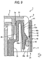
- the lock receiving portion 4 includes a tubular portion 40 formed integrally with the upstanding portion 46, an elastic piece portion 41, a lock projection 42 serving as an engaging portion, a first projecting portion 43, and second projecting portions 44.
- the tubular portion 40 is formed into a hollow tubular shape with a generally rectangular cross-section, and this tubular portion 40 includes a first wall 40a formed integrally with that end of the upstanding portion 46 remote from the upstanding wall 2c and extending downwardly ( Fig. 8 ), a second wall 40b spaced from the first wall 40b in opposed relation thereto, a third wall 40c having opposite side edges integrally connected respectively to the first and second walls 40a and 40b, and a fourth wall 40d having opposite side edges integrally connected respectively to the first and second walls 40a and 40b.
- the upstanding portion 46 and the first wall 40a are continuous with each other to assume a generally U-shaped cross-section as shown in Fig. 8 .
- the tubular portion 40 extends parallel to the upstanding wall 2c and the upstanding portion 46. Namely, the tubular portion 40 extends in the direction of superposing of the ECU 3 on the body 2.
- the tubular portion 40 is so shaped and sized that the arm portion 52 can be received in this tubular portion 40 with a clearance formed therebetween as shown in Fig. 8 .
- This clearance is formed according to the difference between the dimension of the housing 20 from the upstanding portion 46 to the surface 26e and the dimension of the housing 30 from the outer surface of the side wall 3c to the outer surface of the side wall 3e.
- the elastic piece portion 41 forms part of the first wall 40a as shown in Fig. 9 .
- two slits are formed in the first wall 40a, and extend in the direction of superposing of the ECU 3 on the body 2, and that portion of the first wall 40a lying between the two slits and assuming a strip-like shape defines the elastic piece portion 41.
- One longitudinal end of the elastic piece portion 41 is integrally connected to the upstanding portion 46, while the other end (distal end) thereof serves as a free end, and thus the elastic piece portion 41 has a cantilever-like shape.
- the elastic piece portion 41 can be deformed in a direction of opposing of the upstanding portion 46 and the second wall 40b to each other. This elastic piece portion 41 is inclined toward the second wall 40b such that the distance between the two is gradually decreasing toward the distal end of the elastic piece portion 41.
- the lock projection 42 is formed on a generally longitudinally-central portion of the elastic piece portion 41, and projects toward the second wall 40b.
- the lock projection 42 has a generally triangular cross-section as shown in Fig. 9 .
- This lock projection 42 is adapted to be engaged in the through hole 52a formed in the lock arm 5 when the lock arm 5 is received in the tubular portion 40.
- the first projecting portion 43 is formed on that portion of the elastic piece portion 41 disposed below the lock projection 42, that is, disposed deeper than the lock projection 42 in a direction of inserting of the arm portion 52 into the tubular portion 40, and projects toward the second wall 40b.
- the expression "the first projecting portion 43 projects” means that the first projecting portion 43 projects more toward the second wall 40b than that portion of the elastic piece portion 41 disposed above the lock projection 42.
- the second projecting portions 44 are formed on that portion of the second wall 40b disposed generally below the lock projection 42, that is, disposed deeper than the lock projection 42 in the direction of inserting of the arm portion 52 into the tubular portion 40, and project toward the first wall 40a.
- the expression "the second projecting portions 44 project” means that the second projecting portions 44 project more toward the first wall 40a than that portion of the second wall 40b disposed above the lock projection 42.
- the first projecting portion 43 and the second projecting portions 44 are so disposed that the arm portion 52 can be located and held between the first projecting portion 43 and the second projecting portions 44.
- a dimension between those portion of the elastic piece portion 41 (that is, the first wall 40a) and the second wall 40b which are disposed above the lock projection 42 is larger than a thickness of the arm portion 52 to be located therebetween. Also, a dimension between the first projecting portion 43 and the second projecting portions 44 which are disposed below the lock projection 42 is smaller than the thickness of the arm portion 52 to be located therebetween.
- an internal space of the tubular portion 40 is relatively large, and when a distal end portion of the arm portion 52 slides over the lock projection 42, this distal end portion is held between (or gripped by) the first projecting portion 43 and the second projecting portions 44, so that the arm portion 52 (that is, the lock arm 5) is located in a predetermined position.
- This predetermined position means a position where the lock arm 5 is located when the ECU 3 is located in a predetermined position (that is, a proper mounting position) relative to the body 2. Namely, when the lock arm 5 is located in its predetermined position, the ECU 3 is located in its predetermined position relative to the body 2.
- the first wall 40a is formed by the elastic piece portion 41 having elasticity, and therefore when this elastic piece portion 41 is elastically deformed toward the upstanding portion 46, the arm portion 52 is held between the elastic piece portion 41 and the second projecting portions 44 with no clearance formed therebetween. Therefore, the lock arm 5 is positively located in the predetermined position thereof.
- each shaft portion 72 is slid over (that is, moved in sliding contact with) the mounting surface portion 2a toward the inner end of the corresponding receiving recess 60, with the ECU 3 kept inclined relative to the mounting surface portion 2a as shown in Figs. 2 and 5 , and as a result the rotation portions 7 are located or received respectively in the receiving recesses 60.
- the rotation portions 7 are inserted respectively into the receiving recesses 60 until the side wall 3e of the ECU 3 is brought into abutting engagement with the first limitation walls 61, and in this condition the ECU 3 is rotatably moved about the shaft portions 72 in such a manner that the other end (that is, the side wall 3c) of the ECU 3 is moved toward the mounting surface portion 2a as shown in Fig. 6 .
- the lower wall 3b of the ECU 3 is superposed on the mounting surface portion 2a, and also the lock arm 5 is engaged with the lock receiving portion 4, thereby fixing the ECU 3 to the body 2 as shown in Figs. 3 and 7 .
- the ECU 3 is attached to the body 2.
- the lock arm 5 is located in the predetermined position thereof by the first projecting portion 43 and the second projecting portions 44 at a final stage of the operation of engagement of the lock arm 5 with the lock receiving portion 4, and therefore the ECU 3 is located in its predetermined position (that is, its proper attaching position) relative to the body 2 at a final stage of the operation of attaching of the ECU 3 on the body 2. Therefore, a relative shaking movement between the ECU 3 and the body 2 in the direction of opposing of the side walls 3e and 3c to each other is prevented from developing.
- each shaft portion 72 is prevented by the first and second limitation walls 61 and 62 from being disengaged from the receiving recess 60. And besides, simultaneously when the ECU 3 is attached to the body 2, the connectors 24 and 34 are fitted together, so that the printed circuit boards 21 and 31 are electrically connected together.
- the projecting portions 43 and 44 are formed on and project from those portions of the inner surface of the tubular portion 40 disposed deeper than the lock projection 42 in the direction of inserting of the arm portion 52 into the tubular portion 40, and abut against the arm portion 52 to locate the lock arm 5 in the predetermined position thereof, thereby locating the ECU 3 in the predetermined position thereof relative to the body 2. Therefore, even when a clearance is formed between the tubular portion 40 and the arm portion 52, the development of a relative shaking movement between the ECU 3 and the body 2 after attaching the ECU 3 to the body 2 can be prevented merely by engaging the lock arm 5 with the lock receiving portion 4 without the need for fixing the ECU 3 and the body 3 together by screws or the like. Therefore, there can be provided the electrical connection box 1 in which the ECU 3 can be easily attached to the body 2 without being caught thereon, and also a relative shaking movement between the ECU 3 and the body 2 can be prevented from developing after the ECU 3 is attached to the body 2.
- the first projecting portion 43 and the second projecting portions 44 are so disposed as to hold the arm portion 52 therebetween, and therefore the arm portion 52 can be located in a generally central region of the tubular portion 40 in the direction of opposing of the first projecting portion 43 and the second projecting portions 44 to each other, and therefore the arm portion 52 can be positioned (that is, located in the above predetermined position) with a smaller amount of movement of the arm portion 52 as compared with the case where the arm portion 52 is positioned by causing a projecting portion to abut against only one side (or surface) of the arm portion 52 such that the arm portion 52 abuts against that portion of the inner surface of the tubular portion 40 opposed to this projecting portion. Therefore, the ECU 3 can be more smoothly attached to the body 2.
- the two second projecting portions 44 are formed on and along the inner surface of the second wall 40b, and are spaced from each other in the direction perpendicular to the direction of superposing of the ECU 3 on the body 2. Therefore, the area of contact of these second projecting portions 44 with the arm portion 52 can be reduced, and a frictional resistance can be reduced, and therefore the arm portion 52 can be located in the predetermined position within the tubular portion 40 with a smaller force. And besides, a lightweight design of the electrical connection box 1 can be achieved.
- the electrical connection box includes the hinges 8, and the fixing portion 9 as described above, and therefore the shaft portions 72 are located respectively in the receiving recesses 60, and then the ECU 3 is pivotally moved toward the body 2 about these shaft portions 72, and merely by doing so, the ECU 3 can be easily attached to the body 2. Namely, it is not necessary to precisely position the ECU 3, and also it is not necessary to fix the ECU 3 to the body 2 by separate parts such as screws, and therefore the ECU 3 can be quite easily attached to the base 2.
- the ECU 3 while pivotally moved about the hinges 8, is attached to the body 2, and with this construction a larger clearance must be formed between the housing 30 and the housing 20, and also a larger clearance must be formed between the tubular portion 40 and the arm portion 52 as compared with the case where the ECU 3 is moved linearly toward the body 2, and is attached thereto.
- the first and second projecting portions 43 and 44 for locating the lock arm 5 in the predetermined position thereof (that is, for locating the ECU 3 in the predetermined position thereof), and therefore even when such large clearances are provided, a relative shaking movement can be prevented from developing between the ECU 3 and the body 2.
- a relative shaking movement between the ECU 3 and the body 2 can be prevented as described above, and therefore wear of the terminals 22 and 32 of the connectors 24 and 34 can be prevented, and also the reliability of connection between the terminals 22 and the terminals 32 and hence the reliability of connection between the printed circuit boards 21 and 31 can be secured.
- the mounting member is not limited to such ECU, and any other mounting member such as a case, a part, etc., can be used in so far as it can be attached to the body 2.
- each of the body and the mounting member does not always need to have the printed circuit board and the connector.
- the through hole 52a serving as the projection receiving portion is formed in the arm portion 52, and the lock projection 42 is formed on the tubular portion 40.
- the lock projection may be formed on the arm portion 52, while the projection receiving portion may be provided at the tubular portion 40.
- the projection receiving portion does not always need to be the through hole, and may be a depressed portion or recess.
- the lock receiving portion may be provided at the ECU 3, while the lock arm may be formed on the body 2.
- the two second projecting portions 44 are disposed on the common plane, and are arranged in spaced relation to each other in the direction perpendicular to the direction of superposing of the ECU 3 on the body 2.
- the plurality of projecting portions may be arranged in any other suitable direction in so far as these projecting portions are formed at those portions of the inner surface of the tubular portion 40 disposed deeper than the lock projection 42 in the direction of inserting of the arm portion 52 into the tubular portion 40.
- at least one projecting portion is provided on the inside of the tubular portion 40, this is acceptable.
- the above embodiment is directed to the electrical connection box 1 in which the ECU 3 and the body 2 are pivotally connected together through the hinges 8.
- the ECU 3 and the body 2 do not always need to be connected together through the hinges 8, and for example, the electrical connection box may be of the type in which the fixing portion 9 is provided at one ends of the ECU 3 and the body 2, and also another fixing portion 9 is provided at the other ends of the ECU and the body.
Landscapes
- Connection Or Junction Boxes (AREA)
- Details Of Connecting Devices For Male And Female Coupling (AREA)
- Casings For Electric Apparatus (AREA)
Claims (8)
- Boîte de raccordement électrique, comportant :un corps (2) :un élément de montage (3) fixé sur le corps ;un bras de blocage (5) qui est prévu sur l'un du corps et de l'élément de montage, le bras de blocage comprenant :une partie de bras (52), etune première partie d'engagement (52a) prévue au niveau de la partie de bras ;une partie de réception de blocage (4) qui est prévue au niveau de l'autre du corps et de l'élément de montage, la partie de réception de blocage comprenant :une partie de réception qui a une partie d'insertion pour recevoir la partie de bras ; etune deuxième partie d'engagement (42) prévue sur une surface de la partie de réception de façon à être engagée dans la première partie d'engagement,la partie de bras s'étendant généralement dans une direction d'insertion dans laquelle la partie de bras entre dans la partie de réception ;caractérisée en ce que la partie de réception comprend une saillie (44) qui dépasse davantage de la surface de la partie de réception que la deuxième partie d'engagement de la partie d'insertion de façon à buter sur la partie de bras afin de positionner le bras de blocage dans une position prédéterminée ; etquand la première partie d'engagement engage la deuxième partie d'engagement, un jeu est formé entre la partie de réception et la partie de bras.
- Boîte de raccordement électrique selon la revendication 1, dans laquelle une de la première partie d'engagement (52a) et de la deuxième partie d'engagement a un trou débouchant ; et
dans laquelle l'autre de la première partie d'engagement et de la deuxième partie d'engagement a une forme convexe. - Boîte de raccordement électrique selon la revendication 1, dans laquelle une de la première partie d'engagement et de la deuxième partie d'engagement a une forme concave ; et
dans laquelle l'autre de la première partie d'engagement et de la deuxième partie d'engagement a une forme convexe. - Boîte de raccordement électrique selon la revendication 1, dans laquelle une pluralité de saillies (44) de façon à maintenir la partie de bras entre elles.
- Boîte de raccordement électrique selon la revendication 1, dans laquelle une pluralité de saillies (44) est prévue d'une manière telle que les saillies sont espacées l'une de l'autre le long de la surface de la partie de réception.
- Boîte de raccordement électrique selon la revendication 1, dans laquelle un jeu est formé entre une paroi extérieure procurant le bras de blocage et une paroi extérieure procurant la partie de réception de blocage.
- Boîte de raccordement électrique selon la revendication 1, dans laquelle le corps et l'élément de montage sont reliés ensemble de façon rotative au niveau de leurs premières extrémités par l'intermédiaire d'une charnière ; et
dans laquelle le bras de blocage (5) et la partie de réception de blocage (4) sont prévus au niveau des autres extrémités du corps (2) et de l'élément de montage (3). - Boîte de raccordement électrique selon la revendication 1, dans laquelle le corps (2) comprend une première carte (21) ayant un premier connecteur (24) ;
dans laquelle l'élément de montage (3) comprend une deuxième carte (31) ayant un deuxième connecteur (34) ; et
dans laquelle, quand l'élément de montage est fixé sur le corps, le premier connecteur est monté sur le deuxième connecteur de telle sorte que la première carte est électriquement reliée à la deuxième carte.
Applications Claiming Priority (1)
| Application Number | Priority Date | Filing Date | Title |
|---|---|---|---|
| JP2007002380A JP5101891B2 (ja) | 2007-01-10 | 2007-01-10 | 電気接続箱 |
Publications (3)
| Publication Number | Publication Date |
|---|---|
| EP1944835A2 EP1944835A2 (fr) | 2008-07-16 |
| EP1944835A3 EP1944835A3 (fr) | 2012-12-12 |
| EP1944835B1 true EP1944835B1 (fr) | 2013-12-04 |
Family
ID=39276065
Family Applications (1)
| Application Number | Title | Priority Date | Filing Date |
|---|---|---|---|
| EP08000306.4A Active EP1944835B1 (fr) | 2007-01-10 | 2008-01-09 | Boîtier de connexion électrique |
Country Status (5)
| Country | Link |
|---|---|
| US (1) | US7534126B2 (fr) |
| EP (1) | EP1944835B1 (fr) |
| JP (1) | JP5101891B2 (fr) |
| CN (1) | CN101222126B (fr) |
| AU (1) | AU2008200090B2 (fr) |
Families Citing this family (14)
| Publication number | Priority date | Publication date | Assignee | Title |
|---|---|---|---|---|
| FI122846B (fi) * | 2010-05-19 | 2012-07-31 | Schneider Electric Finland Oy | Kiinnitysosa peitelevyn kiinnittämiseksi kojerasiasovitelman yhteyteen, kojerasiasovitelma ja peitelevyn kiinnitysjärjestely |
| JP5798781B2 (ja) * | 2011-01-28 | 2015-10-21 | 矢崎総業株式会社 | 電気接続箱 |
| JP5813386B2 (ja) * | 2011-06-21 | 2015-11-17 | 矢崎総業株式会社 | 電気接続箱 |
| JP5785811B2 (ja) * | 2011-08-02 | 2015-09-30 | 矢崎総業株式会社 | 防水ボックス及びそれを備えた電気接続箱 |
| JP5853592B2 (ja) * | 2011-10-28 | 2016-02-09 | 住友電装株式会社 | 電気部品収納ボックス |
| JP5912610B2 (ja) * | 2012-02-07 | 2016-04-27 | 矢崎総業株式会社 | ねじ締めブロックの係止構造 |
| JP5828290B2 (ja) * | 2012-02-27 | 2015-12-02 | 株式会社オートネットワーク技術研究所 | 電気接続箱 |
| EP2648284A1 (fr) * | 2012-04-02 | 2013-10-09 | Siemens Aktiengesellschaft | Prise frontale pour un composant SPS |
| JP5704350B2 (ja) * | 2012-06-20 | 2015-04-22 | 住友電装株式会社 | 電気接続箱 |
| JP6256414B2 (ja) * | 2015-06-05 | 2018-01-10 | 住友電装株式会社 | 電気接続箱及び電気接続箱の防水構造 |
| JP6458745B2 (ja) * | 2016-02-18 | 2019-01-30 | オムロン株式会社 | 装置ユニット |
| DE102016117330A1 (de) * | 2016-09-15 | 2018-03-15 | Knorr-Bremse Systeme für Nutzfahrzeuge GmbH | Gehäuse für ein Steuergerät und Abdeckhaube für das Gehäuse |
| JP6826079B2 (ja) * | 2018-08-21 | 2021-02-03 | 矢崎総業株式会社 | ロック構造、電気接続箱及びワイヤハーネス |
| CN109798037B (zh) * | 2019-01-24 | 2021-06-22 | 宁波吉利汽车研究开发有限公司 | 一种主动式铰链 |
Family Cites Families (20)
| Publication number | Priority date | Publication date | Assignee | Title |
|---|---|---|---|---|
| US3617985A (en) * | 1969-10-24 | 1971-11-02 | Motorola Inc | Accessory connector |
| US3883856A (en) * | 1972-01-31 | 1975-05-13 | Sony Corp | Program input system using a memory cassette |
| JPS6440224U (fr) * | 1987-09-07 | 1989-03-10 | ||
| JPH02155676A (ja) * | 1988-12-07 | 1990-06-14 | Nec Niigata Ltd | 印字装置の紙送り機構におけるガタ防止機構 |
| FR2691216B1 (fr) * | 1992-05-18 | 1995-12-15 | Landis Gyr Energy Management | Dispositif d'assemblage par clipsage, pouvant etre rendu indemontable, et avec rattrapage de jeu. |
| JPH08107617A (ja) * | 1994-10-06 | 1996-04-23 | Yazaki Corp | カバー係止構造 |
| JP3599065B2 (ja) * | 1995-03-03 | 2004-12-08 | 株式会社ニフコ | 部品の仮止め構造 |
| JPH094612A (ja) * | 1995-06-20 | 1997-01-07 | Matsushita Electric Works Ltd | 取付装置 |
| JPH09163552A (ja) * | 1995-12-07 | 1997-06-20 | Yazaki Corp | 電気接続箱 |
| JP3408079B2 (ja) * | 1996-09-26 | 2003-05-19 | ダイハツ工業株式会社 | 電気接続箱 |
| JP3414307B2 (ja) * | 1999-03-09 | 2003-06-09 | 住友電装株式会社 | 電気接続箱 |
| JP2000316219A (ja) * | 1999-04-27 | 2000-11-14 | Sumitomo Wiring Syst Ltd | 電気接続箱 |
| JP2001057723A (ja) * | 1999-08-10 | 2001-02-27 | Yazaki Corp | 電気接続箱への電子ユニット取付構造 |
| JP3365365B2 (ja) | 1999-09-02 | 2003-01-08 | 住友電装株式会社 | 電気接続箱の取付構造 |
| CN2485827Y (zh) * | 2001-06-04 | 2002-04-10 | 瀚荃股份有限公司 | 对电路板固定的连接器 |
| JP3948657B2 (ja) * | 2002-07-16 | 2007-07-25 | 矢崎総業株式会社 | 電気接続箱 |
| US6743035B1 (en) * | 2003-10-27 | 2004-06-01 | Speed Tech Corp | Electronic card connector |
| JP2005176539A (ja) | 2003-12-12 | 2005-06-30 | Yazaki Corp | 箱体の固定構造 |
| JP4342433B2 (ja) | 2004-12-24 | 2009-10-14 | 矢崎総業株式会社 | ジャンクションボックス |
| DE102005047298B3 (de) * | 2005-09-30 | 2007-05-16 | Sirona Dental Systems Gmbh | Befestigungsvorrichtung für eine Steckverbindung mit zwei Anschlussteilen insbesondere für einen zahnärztlichen Behandungsplatz |
-
2007
- 2007-01-10 JP JP2007002380A patent/JP5101891B2/ja active Active
-
2008
- 2008-01-08 US US11/970,869 patent/US7534126B2/en active Active
- 2008-01-08 AU AU2008200090A patent/AU2008200090B2/en active Active
- 2008-01-09 EP EP08000306.4A patent/EP1944835B1/fr active Active
- 2008-01-10 CN CN2008100004473A patent/CN101222126B/zh active Active
Also Published As
| Publication number | Publication date |
|---|---|
| US7534126B2 (en) | 2009-05-19 |
| JP5101891B2 (ja) | 2012-12-19 |
| JP2008172891A (ja) | 2008-07-24 |
| AU2008200090A1 (en) | 2008-07-24 |
| EP1944835A2 (fr) | 2008-07-16 |
| CN101222126B (zh) | 2010-06-16 |
| EP1944835A3 (fr) | 2012-12-12 |
| US20080164793A1 (en) | 2008-07-10 |
| CN101222126A (zh) | 2008-07-16 |
| AU2008200090B2 (en) | 2011-02-03 |
Similar Documents
| Publication | Publication Date | Title |
|---|---|---|
| EP1944835B1 (fr) | Boîtier de connexion électrique | |
| US7777132B2 (en) | Electrical connection box | |
| US7507094B2 (en) | Electrical connection box and assembling method of electrical connection box | |
| US7402071B2 (en) | Connector system having a connection detecting mechanism | |
| KR101211764B1 (ko) | 커넥터 장치 | |
| US7232323B2 (en) | Electrical zero insertion force connector | |
| JP2007220542A (ja) | コネクタ | |
| JP2006216501A (ja) | ジョイントコネクタ及びジョイントコネクタの組み立て方法 | |
| US7540770B2 (en) | Electrical connector | |
| JP4914712B2 (ja) | 電子回路基板とコネクタの接続構造 | |
| KR101530431B1 (ko) | 커넥터 장치 | |
| US11404819B2 (en) | Contact device, contact system having such a contact device and method for producing such a contact system | |
| US20030104729A1 (en) | Connector mounting construction | |
| AU2003270998A1 (en) | Assembly for an electronic control unit | |
| JP2008172893A (ja) | 電気接続箱 | |
| JPH0831510A (ja) | コネクタ構造 | |
| JP2006140089A (ja) | 待受けコネクタの嵌合構造 | |
| JP2557720Y2 (ja) | フレキシブルプリント配線板用コネクタ | |
| JP2542233Y2 (ja) | 電気コネクタ構造 | |
| KR101561044B1 (ko) | 플렉시블 케이블용 커넥터 | |
| KR100955054B1 (ko) | 커넥터 어셈블리 및 이의 결합방법 | |
| JP2545049Y2 (ja) | 電気コネクタのプリント配線板に対する止着手段 | |
| EP3316412A1 (fr) | Connecteur destiné à connecter un câble électrique à une carte | |
| JPH10321291A (ja) | コネクタの取付構造 | |
| JP3980944B2 (ja) | 接続装置 |
Legal Events
| Date | Code | Title | Description |
|---|---|---|---|
| PUAI | Public reference made under article 153(3) epc to a published international application that has entered the european phase |
Free format text: ORIGINAL CODE: 0009012 |
|
| AK | Designated contracting states |
Kind code of ref document: A2 Designated state(s): AT BE BG CH CY CZ DE DK EE ES FI FR GB GR HR HU IE IS IT LI LT LU LV MC MT NL NO PL PT RO SE SI SK TR |
|
| AX | Request for extension of the european patent |
Extension state: AL BA MK RS |
|
| PUAL | Search report despatched |
Free format text: ORIGINAL CODE: 0009013 |
|
| AK | Designated contracting states |
Kind code of ref document: A3 Designated state(s): AT BE BG CH CY CZ DE DK EE ES FI FR GB GR HR HU IE IS IT LI LT LU LV MC MT NL NO PL PT RO SE SI SK TR |
|
| AX | Request for extension of the european patent |
Extension state: AL BA MK RS |
|
| RIC1 | Information provided on ipc code assigned before grant |
Ipc: H01R 13/627 20060101AFI20121108BHEP |
|
| 17P | Request for examination filed |
Effective date: 20130226 |
|
| GRAP | Despatch of communication of intention to grant a patent |
Free format text: ORIGINAL CODE: EPIDOSNIGR1 |
|
| RIC1 | Information provided on ipc code assigned before grant |
Ipc: H01R 13/627 20060101AFI20130417BHEP |
|
| INTG | Intention to grant announced |
Effective date: 20130510 |
|
| AKX | Designation fees paid |
Designated state(s): DE FR GB |
|
| GRAS | Grant fee paid |
Free format text: ORIGINAL CODE: EPIDOSNIGR3 |
|
| GRAA | (expected) grant |
Free format text: ORIGINAL CODE: 0009210 |
|
| AK | Designated contracting states |
Kind code of ref document: B1 Designated state(s): DE FR GB |
|
| REG | Reference to a national code |
Ref country code: GB Ref legal event code: FG4D |
|
| REG | Reference to a national code |
Ref country code: DE Ref legal event code: R096 Ref document number: 602008029052 Country of ref document: DE Effective date: 20140130 |
|
| REG | Reference to a national code |
Ref country code: DE Ref legal event code: R097 Ref document number: 602008029052 Country of ref document: DE |
|
| PLBE | No opposition filed within time limit |
Free format text: ORIGINAL CODE: 0009261 |
|
| STAA | Information on the status of an ep patent application or granted ep patent |
Free format text: STATUS: NO OPPOSITION FILED WITHIN TIME LIMIT |
|
| 26N | No opposition filed |
Effective date: 20140905 |
|
| REG | Reference to a national code |
Ref country code: DE Ref legal event code: R097 Ref document number: 602008029052 Country of ref document: DE Effective date: 20140905 |
|
| REG | Reference to a national code |
Ref country code: FR Ref legal event code: PLFP Year of fee payment: 9 |
|
| REG | Reference to a national code |
Ref country code: FR Ref legal event code: PLFP Year of fee payment: 10 |
|
| REG | Reference to a national code |
Ref country code: FR Ref legal event code: PLFP Year of fee payment: 11 |
|
| PGFP | Annual fee paid to national office [announced via postgrant information from national office to epo] |
Ref country code: GB Payment date: 20231130 Year of fee payment: 17 |
|
| PGFP | Annual fee paid to national office [announced via postgrant information from national office to epo] |
Ref country code: FR Payment date: 20231212 Year of fee payment: 17 |
|
| PGFP | Annual fee paid to national office [announced via postgrant information from national office to epo] |
Ref country code: DE Payment date: 20231128 Year of fee payment: 17 |