EP1936324B1 - Method for processing detection signal of vibratory inertial force sensor and vibratory inertial force sensor - Google Patents
Method for processing detection signal of vibratory inertial force sensor and vibratory inertial force sensor Download PDFInfo
- Publication number
- EP1936324B1 EP1936324B1 EP06811477.6A EP06811477A EP1936324B1 EP 1936324 B1 EP1936324 B1 EP 1936324B1 EP 06811477 A EP06811477 A EP 06811477A EP 1936324 B1 EP1936324 B1 EP 1936324B1
- Authority
- EP
- European Patent Office
- Prior art keywords
- signal
- detection
- drive arm
- inertial force
- sensor
- Prior art date
- Legal status (The legal status is an assumption and is not a legal conclusion. Google has not performed a legal analysis and makes no representation as to the accuracy of the status listed.)
- Active
Links
Images


Classifications
-
- G—PHYSICS
- G01—MEASURING; TESTING
- G01C—MEASURING DISTANCES, LEVELS OR BEARINGS; SURVEYING; NAVIGATION; GYROSCOPIC INSTRUMENTS; PHOTOGRAMMETRY OR VIDEOGRAMMETRY
- G01C19/00—Gyroscopes; Turn-sensitive devices using vibrating masses; Turn-sensitive devices without moving masses; Measuring angular rate using gyroscopic effects
- G01C19/56—Turn-sensitive devices using vibrating masses, e.g. vibratory angular rate sensors based on Coriolis forces
- G01C19/5607—Turn-sensitive devices using vibrating masses, e.g. vibratory angular rate sensors based on Coriolis forces using vibrating tuning forks
-
- G—PHYSICS
- G01—MEASURING; TESTING
- G01C—MEASURING DISTANCES, LEVELS OR BEARINGS; SURVEYING; NAVIGATION; GYROSCOPIC INSTRUMENTS; PHOTOGRAMMETRY OR VIDEOGRAMMETRY
- G01C19/00—Gyroscopes; Turn-sensitive devices using vibrating masses; Turn-sensitive devices without moving masses; Measuring angular rate using gyroscopic effects
- G01C19/56—Turn-sensitive devices using vibrating masses, e.g. vibratory angular rate sensors based on Coriolis forces
- G01C19/5607—Turn-sensitive devices using vibrating masses, e.g. vibratory angular rate sensors based on Coriolis forces using vibrating tuning forks
- G01C19/5614—Signal processing
Definitions
- the present invention relates to a method for processing a detection signal of vibratory inertial force sensor, and it also relates to a vibratory inertial force sensor adopting the same method.
- Fig. 6 shows a block diagram of a vibratory angular velocity sensor comprising the following elements:
- the detection signal supplied from sensor section 202 is differentially amplified by differential amplifier 206.
- the amplified signal and an inverted signal of the detection signal inverted by inverting amplifier 207 are synchronously wave-detected by synchronous wave detector 208.
- the resultant signal is smoothed by low-pass filter 209, so that the signal with disturbance noise, such as external impact, suppressed is output.
- Conventional low-pass filter 209 firstly amplifies the signal having undergone the synchronous wave-detection with inverting amplifier 220 working as a pre-amplifier, then smoothes the resultant signal with smoothing circuit 221, or the signal is amplified and smoothed at the same time by an active filter (not shown).
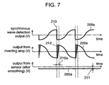
- the signal having undergone the synchronous wave-detection in wave detector 208 draws a saw-tooth waveform as drawn by synchronous wave-detection output 208a shown in Fig. 7 .
- the amplifying capacity of inversing amplifier 220 or the active filter working as a pre-amplifier of the low-pass filter cannot fully track the saw-tooth waveform, so that the waveform actually drawn by output 220a from the inversing amplifier becomes as shown in Fig. 7 .
- the horizontal axis represents a time
- the vertical axis represents an electrical potential of respective output signals.
- output 220a supplied from the inverting amplifier and having undergone the amplification includes waveform error 212 which causes offset 211 at sensor output 205a having undergone the smoothing.
- Smoothing circuit 221 of low-pass filter 209 thus cannot implement an accurate smoothing process, so that the performance of the vibratory inertial force sensor is obliged to lower due to internal process within detection circuit 205.
- a vibratory gyroscope includes a synchronous detection unit that detects a sense signal sent from a sensing element using a reference signal synchronous with a monitor signal.
- an analog moving-average filter that produces a moving average of the detection signal by sampling the detection signal during one cycle of the reference signal is used to remove high-frequency noise components from the detection signal, which is detected to be synchronous with the reference signal, without the necessity of a CR filter that requires a large time constant. Consequently, unnecessary noise components whose frequencies are equal to the frequency of the reference signal and those of its harmonics, and which stem from synchronous detection, can be efficiently attenuated owing to an infinite attenuation frequency band offered by the analog moving-average filter.
- US5806364 discloses a vibration-type angular velocity detector for accurately correcting temperature-induced variations of an angular velocity signal without using a temperature sensor.
- a driving piezoelectric element, a detecting piezoelectric element and reference piezoelectric element are disposed on a vibration element.
- a feedback control loop for applying driving voltage to the driving piezoelectric element is provided using an amplifier, a phase-shifting circuit, a rectifier, a reference voltage generator, a differential amplifier and a multiplier so as to vibrate the vibration element at a fixed amplitude.
- an angular velocity signal is output
- the output voltage of the differential amplifier is a signal corresponding to the temperature of the vibration element.
- a correction signal is prepared by a correction signal preparing circuit using the differential amplifier output signal added to the angular velocity signal by a summer so that the temperature correction of the angular velocity signal is performed.
- US2005204815 discloses a vibration type angular velocity sensor including a first and a second angular velocity sensors and an anomaly monitoring signal generating and outputting unit including an opposite phase waveform synthesis portion.
- the first and the second angular velocity sensors include: a vibrator, a vibration driving unit, and a detection waveform generation unit.
- the opposite phase waveform synthesis portion synthesizes the first and the second detection waveforms with opposite phase.
- the anomaly monitoring signal generating and outputting unit generates and outputs an anomaly monitoring signal on the basis of a synthesized opposite phase wavefonn synthesized from the first and the second detection waveforms.
- the present invention addresses the problem discussed above, and aims to provide a method for improving detection accuracy in processing a detection signal of vibratory inertial force sensor, and it also aims to provide a vibratory inertial force sensor adopting the same method.
- the present invention relates to a method according to claim 1 and a vibratory inertial force sensor according to claim 2.
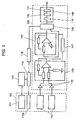
- FIG. 1 shows a block diagram of a vibratory angular velocity sensor as an example of a vibratory inertial force sensor of the present invention.
- This vibratory angular velocity sensor basically comprises the following elements:
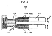
- Fig. 2 shows a top view detailing the structure of sensor element 103 to be used in the vibratory angular velocity sensor of the present invention.
- sensor element 103 comprises the following elements:
- Drive control circuit 104 shown in Fig. 1 applies a drive power to drive electrodes 101a, thereby vibrating drive arms 114 to both sides as arrow marks 116 show. In this vibration state, an angular velocity around the sensing axis is applied to arms 114, so that drive arms 114 deflect along back and forth direction in Fig. 2 due to Coriolis force. The deflection allows sensor electrodes 102a to output a detection signal to detection circuit 105 shown in Fig. 1 .
- a drive power applied from drive control circuit 104 to drive electrode 101a is adjusted so as to accomplish the following performance:
- Each one of monitor electrodes 115a shown in Fig. 2 senses an amount of amplitude of drive arms 114, and feeds back this information to drive control circuit 104 via monitor 115, so that the amount of amplitude becomes a specified state.
- Fig. 3 shows transition of waveforms of respective signals in the vibratory angular velocity sensor in accordance with this embodiment.
- the horizontal axis represents a time
- the vertical axis represents an electric potential of respective signals.
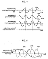
- Figs. 4 and 5 use the same system as Fig. 3 .
- detection signals (sensed outputs 102b, 102c shown in Fig. 3 ) supplied from two sensor electrodes 102a disposed at sensor element 103 are amplified by amplifier 110 formed of a current amplifier or a charge amplifier. Then the two amplified signals are differentially amplified by differential amplifier 106, and the resultant signals are delayed their phase by 90 degrees by phase shifter 117 with respect to these resultant signals (output 106a from the differential amplifier shown in Fig. 3 ) having undergone the differential amplification.
- the phase-delayed signal (output 117a from the phase shifter shown in Fig.
- a first branched signal is fed directly into synchronous detector 108, and a second branched signal is reversed the phase by inverting amplifier 107 before the resultant signal (output 107a from the inverting amplifier shown in Fig. 3 ) is fed into synchronous wave detector 108.
- Wave detector clock section 118 converts monitor signal 115b supplied from monitor 115 into wave-detection CLK output 118a drawing a pulse waveform (an output from the wave detector clock section) shown in Fig. 3 . Then in synchronous wave detector 108, those two input signals (output 117a from the phase shifter and output 107a from the inverting amplifier shown in Fig. 3 ) are wave-detected by output 118a from wave detector clock section 118, thereby forming synchronous wave detection output 108a drawing a saw-tooth waveform shown in Fig. 3 .
- This vibratory angular velocity sensor has low-pass filter 109 shown in Fig. 1 and which filter 109 smoothes saw-tooth synchronous wave-detection output 108a.
- Low-pass filter 109 works in the following manner: synchronous wave-detection output 108a undergoes passive filter 119 for removing the harmonic component, then is smoothed by smoothing circuit 121 such as an integrator.
- smoothing circuit 121 such as an integrator.
- This mechanism allows suppressing a reduction in detection accuracy of detection circuit 105 comparing with the conventional one shown in Fig. 7 , where synchronous wave-detection output 208a is firstly amplified, and then smoothed. As a result, the detection accuracy of the vibratory inertial force sensor can be improved.
- the passive filter discussed above is a filter formed of passive components only, such as capacitors, resistors and so on.
- the conventional pre-amplifier or active filter firstly amplifies and then smoothes synchronous wave-detection output 208a, i.e. saw-tooth shaped output 208a is amplified by the pre-amp or the active filter, thereby incurring time lag 210a at a switchover section of the waveform due to the poor tracking ability of the amplifier.
- waveform error 212 is generated between an actual waveform and the amplified waveform.
- the actual waveform with error 212 is smoothed, thereby producing offset 211 in the output.
- synchronous wave-detection output 108a or 208a supplied from synchronous wave detector 108 shown in Fig. 1 or wave detector 208 shown in Fig. 6 includes secondary harmonic component 219b and tertiary harmonic component 219c on top of fundamental harmonic component 219a shown in Fig. 5 . Therefore, as shown in Fig. 4 , synchronous wave-detection output 108a is fed into passive filter 119 for removing the harmonic components, and then the resultant output 119a is supplied, which output 119a contains only sine-wave like moderately curved fundamental component 219a. This output 119a supplied from passive filter 119 is amplified by amplifier 120, and the resultant output 120a is smoothed by smoothing circuit 121.
- the foregoing process allows the output from the vibratory angular velocity sensor to become sensor output 105a as shown in Fig. 4 , which output 105a includes no waveform error 212 shown in Fig. 6 , so that the production of offset 211 can be suppressed.
- the reduction in detection accuracy of detection circuit 105 can be suppressed, and improvement in the detection accuracy of the vibratory inertial force sensor can be expected.
- Passive filter 119 that removes harmonic component from detection signals has the following structure although not shown in a drawing specifically: resistors in series with respect to a path of the detection signal, and a capacitor is placed between at least one end of the resistors and a reference electric potential.
- a typical harmonic suppressing circuit can work as passive filter 119.
- the vibratory angular velocity sensor is taken as an example of the vibratory inertial force sensor; however, the present invention is not limited to this example. Any structure that senses inertial force, such as acceleration, by vibrating the drive arm can produce a similar advantage to what is discussed previously.
- the present invention allows a vibratory inertial force sensor to achieve higher detection accuracy, so that it is useful for electronic apparatuses requiring a highly accurate sensor of inertial force among others.
- the present invention is thus well applicable to the industrial use.
Landscapes
- Engineering & Computer Science (AREA)
- Physics & Mathematics (AREA)
- General Physics & Mathematics (AREA)
- Radar, Positioning & Navigation (AREA)
- Remote Sensing (AREA)
- Signal Processing (AREA)
- Gyroscopes (AREA)
Applications Claiming Priority (2)
| Application Number | Priority Date | Filing Date | Title |
|---|---|---|---|
| JP2005296283A JP5458462B2 (ja) | 2005-10-11 | 2005-10-11 | 振動型慣性力検知センサ |
| PCT/JP2006/320164 WO2007043503A1 (ja) | 2005-10-11 | 2006-10-10 | 振動型慣性力検知センサの検出信号処理方法及び振動型慣性力検知センサ |
Publications (3)
| Publication Number | Publication Date |
|---|---|
| EP1936324A1 EP1936324A1 (en) | 2008-06-25 |
| EP1936324A4 EP1936324A4 (en) | 2011-09-14 |
| EP1936324B1 true EP1936324B1 (en) | 2014-03-19 |
Family
ID=37942739
Family Applications (1)
| Application Number | Title | Priority Date | Filing Date |
|---|---|---|---|
| EP06811477.6A Active EP1936324B1 (en) | 2005-10-11 | 2006-10-10 | Method for processing detection signal of vibratory inertial force sensor and vibratory inertial force sensor |
Country Status (6)
| Country | Link |
|---|---|
| US (2) | US7673529B2 (enExample) |
| EP (1) | EP1936324B1 (enExample) |
| JP (1) | JP5458462B2 (enExample) |
| KR (1) | KR100985315B1 (enExample) |
| CN (1) | CN101287961B (enExample) |
| WO (1) | WO2007043503A1 (enExample) |
Families Citing this family (12)
| Publication number | Priority date | Publication date | Assignee | Title |
|---|---|---|---|---|
| JP4935069B2 (ja) * | 2005-12-28 | 2012-05-23 | パナソニック株式会社 | 角速度センサ |
| JP2009162645A (ja) * | 2008-01-08 | 2009-07-23 | Panasonic Corp | 慣性速度センサ信号処理回路およびそれを備える慣性速度センサ装置 |
| JP5338211B2 (ja) * | 2008-09-08 | 2013-11-13 | 株式会社村田製作所 | 振動ジャイロ |
| FR2954489B1 (fr) * | 2009-12-23 | 2014-08-01 | Onera (Off Nat Aerospatiale) | Electrodes et circuits electroniques associes pour gyrometre vibrant pizoelectrique |
| JP5362096B2 (ja) * | 2010-02-17 | 2013-12-11 | 株式会社村田製作所 | 振動型慣性力センサ |
| WO2013132842A1 (ja) * | 2012-03-07 | 2013-09-12 | パナソニック株式会社 | 荷重センサ |
| JP6171380B2 (ja) * | 2013-02-14 | 2017-08-02 | 株式会社リコー | アクチュエータ駆動システムと映像機器 |
| US20140303907A1 (en) * | 2013-04-05 | 2014-10-09 | Kevin M. Roughen | Systems and methods for dynamic force measurement |
| JP2014202616A (ja) * | 2013-04-05 | 2014-10-27 | セイコーエプソン株式会社 | 振動素子、電子デバイス、電子機器および移動体 |
| CN105180915B (zh) * | 2014-06-18 | 2018-05-04 | 立锜科技股份有限公司 | 多微机电元件讯号处理方法与用此方法的复合微机电装置 |
| JP6492949B2 (ja) * | 2015-05-14 | 2019-04-03 | セイコーエプソン株式会社 | 回路装置、物理量検出装置、電子機器及び移動体 |
| JP6354892B2 (ja) * | 2017-05-18 | 2018-07-11 | 株式会社リコー | 位置検出装置と映像機器 |
Citations (1)
| Publication number | Priority date | Publication date | Assignee | Title |
|---|---|---|---|---|
| EP1367367A1 (en) * | 2001-03-09 | 2003-12-03 | Matsushita Electric Industrial Co., Ltd. | Angular velocity sensor |
Family Cites Families (22)
| Publication number | Priority date | Publication date | Assignee | Title |
|---|---|---|---|---|
| JPH02129514A (ja) * | 1988-11-10 | 1990-05-17 | Canon Inc | 角速度センサー |
| WO1996038712A1 (fr) * | 1995-05-30 | 1996-12-05 | Matsushita Electric Industrial Co., Ltd. | Capteur de vitesse angulaire |
| US6705151B2 (en) * | 1995-05-30 | 2004-03-16 | Matsushita Electric Industrial Co., Ltd. | Angular velocity sensor |
| JP3536497B2 (ja) * | 1995-12-21 | 2004-06-07 | 株式会社デンソー | 振動型角速度検出装置 |
| JPH109872A (ja) * | 1996-06-21 | 1998-01-16 | Kinseki Ltd | 角速度センサ |
| JPH1144540A (ja) * | 1997-07-25 | 1999-02-16 | Denso Corp | 振動型角速度センサ |
| JPH1183495A (ja) * | 1997-09-12 | 1999-03-26 | Nikon Corp | 圧電振動子およびこの圧電振動子を用いた圧電振動角速度計 |
| JPH11258355A (ja) * | 1998-03-12 | 1999-09-24 | Taiheiyo Cement Corp | 金属検出装置及びその調整方法及びコンピュータ読み取りが可能な記憶媒体 |
| JP3932661B2 (ja) * | 1998-03-31 | 2007-06-20 | 松下電器産業株式会社 | 角速度センサ駆動回路 |
| JP4019504B2 (ja) * | 1998-06-15 | 2007-12-12 | 松下電器産業株式会社 | 角速度センサ |
| JP3937589B2 (ja) * | 1998-06-16 | 2007-06-27 | 松下電器産業株式会社 | 角速度センサ |
| JP3664950B2 (ja) * | 2000-06-15 | 2005-06-29 | 株式会社村田製作所 | 角速度センサ |
| JP4032681B2 (ja) * | 2001-08-27 | 2008-01-16 | 株式会社デンソー | 同期検波方法及び装置並びにセンサ信号検出装置 |
| JP3964875B2 (ja) * | 2004-02-16 | 2007-08-22 | 株式会社ジャイトロニクス | 角速度センサ |
| EP1734337B1 (en) * | 2004-02-20 | 2014-12-10 | Panasonic Corporation | Angular velocity sensor |
| US7134336B2 (en) * | 2004-03-19 | 2006-11-14 | Denso Corporation | Vibration type angular velocity sensor |
| JP4980063B2 (ja) * | 2004-10-07 | 2012-07-18 | パナソニック株式会社 | 角速度センサ |
| WO2007043504A1 (ja) * | 2005-10-11 | 2007-04-19 | Matsushita Electric Industrial Co., Ltd. | 振動型慣性力検知センサおよびそれを用いた電子機器 |
| JP2007205803A (ja) * | 2006-01-31 | 2007-08-16 | Fujitsu Ltd | センサ信号処理システムおよびディテクタ |
| WO2007129494A1 (ja) * | 2006-04-26 | 2007-11-15 | Murata Manufacturing Co., Ltd. | 角速度センサインタフェース回路および角速度検出装置 |
| US7891245B2 (en) * | 2006-11-22 | 2011-02-22 | Panasonic Corporation | Inertial force sensor including a sense element, a drive circuit, a sigma-delta modulator and a signal processing circuit |
| US7779688B2 (en) * | 2006-12-20 | 2010-08-24 | Epson Toyocom Corporation | Vibration gyro sensor |
-
2005
- 2005-10-11 JP JP2005296283A patent/JP5458462B2/ja not_active Expired - Lifetime
-
2006
- 2006-10-10 WO PCT/JP2006/320164 patent/WO2007043503A1/ja not_active Ceased
- 2006-10-10 KR KR1020087002684A patent/KR100985315B1/ko active Active
- 2006-10-10 CN CN2006800380057A patent/CN101287961B/zh active Active
- 2006-10-10 US US12/065,200 patent/US7673529B2/en active Active
- 2006-10-10 EP EP06811477.6A patent/EP1936324B1/en active Active
-
2009
- 2009-12-23 US US12/646,266 patent/US7886622B2/en active Active
Patent Citations (1)
| Publication number | Priority date | Publication date | Assignee | Title |
|---|---|---|---|---|
| EP1367367A1 (en) * | 2001-03-09 | 2003-12-03 | Matsushita Electric Industrial Co., Ltd. | Angular velocity sensor |
Also Published As
| Publication number | Publication date |
|---|---|
| EP1936324A1 (en) | 2008-06-25 |
| KR100985315B1 (ko) | 2010-10-04 |
| JP5458462B2 (ja) | 2014-04-02 |
| WO2007043503A1 (ja) | 2007-04-19 |
| US20090145224A1 (en) | 2009-06-11 |
| US7673529B2 (en) | 2010-03-09 |
| US7886622B2 (en) | 2011-02-15 |
| JP2007107909A (ja) | 2007-04-26 |
| EP1936324A4 (en) | 2011-09-14 |
| KR20080028474A (ko) | 2008-03-31 |
| CN101287961A (zh) | 2008-10-15 |
| CN101287961B (zh) | 2011-03-23 |
| US20100095772A1 (en) | 2010-04-22 |
Similar Documents
| Publication | Publication Date | Title |
|---|---|---|
| US7886622B2 (en) | Method for processing detection signal of vibratory inertial force sensor and vibratory inertial force sensor | |
| JP2667970B2 (ja) | ミクロ機械加工されたセンサーの補償のための方法及び装置 | |
| JP3536497B2 (ja) | 振動型角速度検出装置 | |
| JP4392599B2 (ja) | センサシステム | |
| US6666091B2 (en) | Angular velocity sensor | |
| US6907784B2 (en) | Vibration type angular velocity sensor | |
| KR20090074788A (ko) | 진동 센서를 사용하여 회전율을 측정하는 장치 | |
| JP2005283481A (ja) | センサシステム | |
| JP2007255890A (ja) | ジャイロ装置 | |
| JPH1144540A (ja) | 振動型角速度センサ | |
| JP5348408B2 (ja) | 物理量検出装置、物理量検出装置の異常診断システム及び物理量検出装置の異常診断方法 | |
| JP2001208546A (ja) | 角速度センサ | |
| JP2007107909A5 (enExample) | ||
| JP5589171B2 (ja) | 物理量検出装置用回路 | |
| JP2010185739A (ja) | 3軸検出角速度センサ | |
| JP2005265724A (ja) | 振動型角速度センサ | |
| JPS60188809A (ja) | 振動型角速度検出装置 | |
| JP2006234710A (ja) | ジャイロ信号検出装置 | |
| JP4591787B2 (ja) | 振動子および角速度測定装置 | |
| JP3028999B2 (ja) | 振動ジャイロ | |
| JP2006250643A (ja) | 角速度センサの異常検出装置 | |
| KR100585893B1 (ko) | 미세 각속도계 및 그의 큐 팩터를 튜닝하는 방법 | |
| JP2006153715A (ja) | 振動ジャイロ | |
| JPH09145377A (ja) | 圧電振動子を用いた検出装置 | |
| JPH0359414A (ja) | 角速度センサ |
Legal Events
| Date | Code | Title | Description |
|---|---|---|---|
| PUAI | Public reference made under article 153(3) epc to a published international application that has entered the european phase |
Free format text: ORIGINAL CODE: 0009012 |
|
| 17P | Request for examination filed |
Effective date: 20080225 |
|
| AK | Designated contracting states |
Kind code of ref document: A1 Designated state(s): DE FR GB |
|
| RIN1 | Information on inventor provided before grant (corrected) |
Inventor name: UEMURA, TAKESHIC/O MATSUSHITA EL.IND.CO.LTD. IPROC |
|
| RIN1 | Information on inventor provided before grant (corrected) |
Inventor name: UEMURA,TAKESHIC/O MATSUSHITA EL.IND.CO.LTD. IPROC |
|
| DAX | Request for extension of the european patent (deleted) | ||
| RAP1 | Party data changed (applicant data changed or rights of an application transferred) |
Owner name: PANASONIC CORPORATION |
|
| RBV | Designated contracting states (corrected) |
Designated state(s): DE FR GB |
|
| A4 | Supplementary search report drawn up and despatched |
Effective date: 20110817 |
|
| RIC1 | Information provided on ipc code assigned before grant |
Ipc: G01P 9/04 20110101ALI20110810BHEP Ipc: G01C 19/56 20060101AFI20110810BHEP |
|
| 17Q | First examination report despatched |
Effective date: 20120314 |
|
| GRAP | Despatch of communication of intention to grant a patent |
Free format text: ORIGINAL CODE: EPIDOSNIGR1 |
|
| RIC1 | Information provided on ipc code assigned before grant |
Ipc: G01C 19/56 20120101AFI20130925BHEP |
|
| INTG | Intention to grant announced |
Effective date: 20131016 |
|
| GRAS | Grant fee paid |
Free format text: ORIGINAL CODE: EPIDOSNIGR3 |
|
| GRAA | (expected) grant |
Free format text: ORIGINAL CODE: 0009210 |
|
| AK | Designated contracting states |
Kind code of ref document: B1 Designated state(s): DE FR GB |
|
| REG | Reference to a national code |
Ref country code: GB Ref legal event code: FG4D |
|
| REG | Reference to a national code |
Ref country code: DE Ref legal event code: R096 Ref document number: 602006040768 Country of ref document: DE Effective date: 20140430 |
|
| REG | Reference to a national code |
Ref country code: DE Ref legal event code: R097 Ref document number: 602006040768 Country of ref document: DE |
|
| PLBE | No opposition filed within time limit |
Free format text: ORIGINAL CODE: 0009261 |
|
| STAA | Information on the status of an ep patent application or granted ep patent |
Free format text: STATUS: NO OPPOSITION FILED WITHIN TIME LIMIT |
|
| PGFP | Annual fee paid to national office [announced via postgrant information from national office to epo] |
Ref country code: GB Payment date: 20141021 Year of fee payment: 9 Ref country code: FR Payment date: 20141022 Year of fee payment: 9 |
|
| 26N | No opposition filed |
Effective date: 20141222 |
|
| REG | Reference to a national code |
Ref country code: DE Ref legal event code: R097 Ref document number: 602006040768 Country of ref document: DE Effective date: 20141222 |
|
| GBPC | Gb: european patent ceased through non-payment of renewal fee |
Effective date: 20151010 |
|
| PG25 | Lapsed in a contracting state [announced via postgrant information from national office to epo] |
Ref country code: GB Free format text: LAPSE BECAUSE OF NON-PAYMENT OF DUE FEES Effective date: 20151010 |
|
| REG | Reference to a national code |
Ref country code: FR Ref legal event code: ST Effective date: 20160630 |
|
| PG25 | Lapsed in a contracting state [announced via postgrant information from national office to epo] |
Ref country code: FR Free format text: LAPSE BECAUSE OF NON-PAYMENT OF DUE FEES Effective date: 20151102 |
|
| PGFP | Annual fee paid to national office [announced via postgrant information from national office to epo] |
Ref country code: DE Payment date: 20251021 Year of fee payment: 20 |