EP1896200B1 - Verfahren und vorrichtung zur gezielten beeinflussung der vorbandgeometrie in einem vorgerüst - Google Patents
Verfahren und vorrichtung zur gezielten beeinflussung der vorbandgeometrie in einem vorgerüst Download PDFInfo
- Publication number
- EP1896200B1 EP1896200B1 EP06742867A EP06742867A EP1896200B1 EP 1896200 B1 EP1896200 B1 EP 1896200B1 EP 06742867 A EP06742867 A EP 06742867A EP 06742867 A EP06742867 A EP 06742867A EP 1896200 B1 EP1896200 B1 EP 1896200B1
- Authority
- EP
- European Patent Office
- Prior art keywords
- rolling
- regulation
- force
- stand
- lateral guides
- Prior art date
- Legal status (The legal status is an assumption and is not a legal conclusion. Google has not performed a legal analysis and makes no representation as to the accuracy of the status listed.)
- Active
Links
- 238000000034 method Methods 0.000 title claims description 14
- 238000005096 rolling process Methods 0.000 claims abstract description 57
- 230000008878 coupling Effects 0.000 claims description 6
- 238000010168 coupling process Methods 0.000 claims description 6
- 238000005859 coupling reaction Methods 0.000 claims description 6
- 230000008859 change Effects 0.000 claims description 5
- 238000005098 hot rolling Methods 0.000 claims description 5
- 230000001105 regulatory effect Effects 0.000 claims description 4
- 238000012544 monitoring process Methods 0.000 claims description 2
- 238000003825 pressing Methods 0.000 claims 2
- 238000005259 measurement Methods 0.000 claims 1
- 238000005452 bending Methods 0.000 abstract description 3
- 230000007547 defect Effects 0.000 abstract 1
- 239000000463 material Substances 0.000 description 5
- 230000015572 biosynthetic process Effects 0.000 description 2
- 239000002655 kraft paper Substances 0.000 description 2
- 238000006243 chemical reaction Methods 0.000 description 1
- 230000006835 compression Effects 0.000 description 1
- 238000007906 compression Methods 0.000 description 1
- 230000001276 controlling effect Effects 0.000 description 1
- 238000010586 diagram Methods 0.000 description 1
- 238000006073 displacement reaction Methods 0.000 description 1
- 230000000694 effects Effects 0.000 description 1
- 230000008030 elimination Effects 0.000 description 1
- 238000003379 elimination reaction Methods 0.000 description 1
- 230000003993 interaction Effects 0.000 description 1
- 238000004886 process control Methods 0.000 description 1
- 230000004044 response Effects 0.000 description 1
Images


Classifications
-
- B—PERFORMING OPERATIONS; TRANSPORTING
- B21—MECHANICAL METAL-WORKING WITHOUT ESSENTIALLY REMOVING MATERIAL; PUNCHING METAL
- B21B—ROLLING OF METAL
- B21B37/00—Control devices or methods specially adapted for metal-rolling mills or the work produced thereby
- B21B37/28—Control of flatness or profile during rolling of strip, sheets or plates
-
- B—PERFORMING OPERATIONS; TRANSPORTING
- B21—MECHANICAL METAL-WORKING WITHOUT ESSENTIALLY REMOVING MATERIAL; PUNCHING METAL
- B21B—ROLLING OF METAL
- B21B37/00—Control devices or methods specially adapted for metal-rolling mills or the work produced thereby
- B21B37/68—Camber or steering control for strip, sheets or plates, e.g. preventing meandering
-
- B—PERFORMING OPERATIONS; TRANSPORTING
- B21—MECHANICAL METAL-WORKING WITHOUT ESSENTIALLY REMOVING MATERIAL; PUNCHING METAL
- B21B—ROLLING OF METAL
- B21B39/00—Arrangements for moving, supporting, or positioning work, or controlling its movement, combined with or arranged in, or specially adapted for use in connection with, metal-rolling mills
- B21B39/14—Guiding, positioning or aligning work
-
- B—PERFORMING OPERATIONS; TRANSPORTING
- B21—MECHANICAL METAL-WORKING WITHOUT ESSENTIALLY REMOVING MATERIAL; PUNCHING METAL
- B21B—ROLLING OF METAL
- B21B2263/00—Shape of product
- B21B2263/02—Profile, e.g. of plate, hot strip, sections
-
- B—PERFORMING OPERATIONS; TRANSPORTING
- B21—MECHANICAL METAL-WORKING WITHOUT ESSENTIALLY REMOVING MATERIAL; PUNCHING METAL
- B21B—ROLLING OF METAL
- B21B2273/00—Path parameters
- B21B2273/04—Lateral deviation, meandering, camber of product
-
- B—PERFORMING OPERATIONS; TRANSPORTING
- B21—MECHANICAL METAL-WORKING WITHOUT ESSENTIALLY REMOVING MATERIAL; PUNCHING METAL
- B21B—ROLLING OF METAL
- B21B37/00—Control devices or methods specially adapted for metal-rolling mills or the work produced thereby
- B21B37/58—Roll-force control; Roll-gap control
- B21B37/62—Roll-force control; Roll-gap control by control of a hydraulic adjusting device
-
- B—PERFORMING OPERATIONS; TRANSPORTING
- B21—MECHANICAL METAL-WORKING WITHOUT ESSENTIALLY REMOVING MATERIAL; PUNCHING METAL
- B21B—ROLLING OF METAL
- B21B39/00—Arrangements for moving, supporting, or positioning work, or controlling its movement, combined with or arranged in, or specially adapted for use in connection with, metal-rolling mills
- B21B39/14—Guiding, positioning or aligning work
- B21B39/16—Guiding, positioning or aligning work immediately before entering or after leaving the pass
Definitions
- the invention relates to a method and an apparatus for hot rolling in a hot strip mill or in Steckel streets, wherein in one or more roughing stands slabs are rolled out into pre-bands.
- the resulting pre-bands should be straight, d. H. they should have little sag and they should not have a thickness wedge over the bandwidth.
- the roughing scaffolding not only has the task of preserving the pre-strip geometry, but also of improving it in a targeted manner, since the slabs entering the scaffolding can already be wedge-shaped or sawed. A change in the Vorbandgeometrie is possible, especially in the first stitches, since the slab thickness in relation to the width is still relatively large and thus a material cross flow in the nip is possible.
- a device for controlling the position of the tape run, in particular during finish rolling is known in which arranged next to the rolled strip guide rails bending bars with guide rollers which are pressed laterally against the rolled strip.
- the position control of these roles is superimposed by a pressure control, which causes a shift in the guide rails or guide rollers in the opening direction when occurring compression forces exceeding a predetermined setpoint.
- the object is procedurally achieved with the characterizing features of claim 1, characterized in that for the targeted influencing the Vorbandgeometrie at least one roughing stand by appropriate regulations a dynamic employment in the roughing stand with fast and powerful side guides before and behind the roughing stand are linked together so that in one or more stitches targeted, reversing or in continuous operation, a säblige or wedged slab is transformed into a straight and wedge-free Vorband.
- Advantageous embodiments are specified in the subclaims.
- the inventive influence on the Vorbandgeometrie is carried out with the help of employment in the horizontal frame and the two adjustable side guides in front of and behind the framework.
- the employment in the horizontal framework ensures a constant strip thickness over the bandwidth (no thickness wedge).
- the appointment is with the pivot to control RAC (R oll A lignment C ontrol), which was not used for roughing stands previously regulated so that the nip remain parallel even if emanating from the band interference.
- Disturbances are mainly an incoming thickness wedge over the bandwidth, temperature differences across the bandwidth, off-center position of the strip in the nip and uneven tension distribution across the bandwidth on the inlet side and the outlet side.
- the principle of the swivel control is that the differential rolling force is measured and a swivel value is calculated by the swivel control. This is then used in each case in half as additional setpoint for the separate position controls the drive and operating side of the scaffold. For the employment of the contact forces by the hydraulic cylinder is then moved accordingly. In principle, the swivel control compensates for the skeletal strain, which arises due to the differential forces.
- the task of the side guides is to prevent curving or twisting of the band (saber formation).
- the side guides on each side are kept parallel and at the same distance from the center of the frame.
- the synchronization of the opposite rulers of a side guide is realized mechanically and the employment carried out with electric or hydraulic drive.
- hydraulically driven lateral guides are best suited, since hydraulic drives are very dynamic and, in addition to regulating the position, also allow force control in order to keep the belt straight.
- the position control keeps the side guides at a distance that is slightly greater than the bandwidth and, for example, at the inlet side, the bandwidth is plus 10 mm and at the outlet side the bandwidth is plus 40 mm.
- Position monitoring increases the force setpoint if the side guides want to escape.
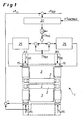
- FIG. 1 is the part of the inventive combination of regulations shown, which relates to the roll adjustment for the horizontal rollers of the roughing stand and that the control scheme of a swivel control RAC.
- back-up rolls 3 and slab 4 shown Vorgerüst 1 cylinder forces F CAS , F CBS , applied to the drive side AS and on the operating side BS by means arranged on the bearing of the upper support roller 3 cylinder cylinder 15 and the resulting forces during rolling continuously measured at the lower bearing support surface of the support rollers.
- the differential rolling force .DELTA.F LC is determined from the obtained force measured values F LcAS and F LcBS and fed together with a reference value .DELTA.F REF to the differential rolling force of the swivel control RAC 20 and a reference swivel value .DELTA.S RAC is calculated here.
- This pivotal value .DELTA.S RAC is then used in half as additional setpoint together with the reference position S REF for the separate position controls 25 of the drive side AS and the operating side BS of the upper support roller 3, the employment then laterally engages the hydraulic cylinders 15.
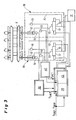
- FIG. 2 shows a roughing stand with back-up rolls 3 and work rolls 2 in a plan view.
- adjusting devices 18 with hydraulic drive.
- These adjusting devices 18 consist, as in the circuit diagram of Fig. 3 can be seen from a common hydraulic unit 11 (hydraulic pump), piston-cylinder units 12, control valves 13 and various hydraulic lines 10.
- measuring devices for determining the piston position 14 and for determining the hydraulic pressure 19 are present.
- the distance of the side guides 8 is widened wedge-shaped at its front end.
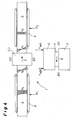
- the two inventively simultaneously performed regulations are shown schematically in their effect.
- the incoming in the rolling direction 7 in the rolling mill slab 4 (the rolling stand is symbolized only by the work roll 2) contains a designated over the slab width with h 0 wedge thickness profile with the drive side AS towards increasing thickness. Due to the rolling process, the wedge-shaped thickness profile was eliminated and a pre-strip with the thickness profile h 1 was produced.
- the case applied by the work rolls 2 rolling force F WAS was on the drive side while greater than the rolling force F WBS on the operating side, whereby a material transverse flow in the direction of arrow 6 from the drive side to the operating side.
- the incoming slab 4 are laterally supported by the side guides 8 and the outgoing pre-strip 5 by the side guides 9.
- the supporting forces F 1 and F 2 in front of and behind the roll stand generate in response the tension profile ⁇ 0 in the incoming slab 4 and the tension profile ⁇ 1 in the outgoing sliver 5.
- These tension profiles ⁇ 0 , ⁇ 1 act on the roll gap and allow the material transverse flow 6, which allows the correction of the geometric error of the slab.
- FIG. 5 are the options described above, the coupling of the employment of the rollers and the side guides according to the invention with the aim to limit the load on the control systems and to distribute the correction of the slab geometry on several stitches, shown schematically.
- the invention is not limited to the illustrated embodiments, but, for example, according to the type of used Vorbandgerüste or drives used for the side guides variable if the inventive measure of linking a pivoting control RAC of the rollers with the mechanical employment of side guides for the rolling continue underlying.
Applications Claiming Priority (2)
| Application Number | Priority Date | Filing Date | Title |
|---|---|---|---|
| DE102005021769A DE102005021769A1 (de) | 2005-05-11 | 2005-05-11 | Verfahren und Vorrichtung zur gezielten Beeinflussung der Vorbandgeometrie in einem Vorgerüst |
| PCT/EP2006/004392 WO2006119984A1 (de) | 2005-05-11 | 2006-05-10 | Verfahren und vorrichtung zur gezielten beeinflussung der vorbandgeometrie in einem vorgerüst |
Publications (2)
| Publication Number | Publication Date |
|---|---|
| EP1896200A1 EP1896200A1 (de) | 2008-03-12 |
| EP1896200B1 true EP1896200B1 (de) | 2011-07-20 |
Family
ID=36691710
Family Applications (1)
| Application Number | Title | Priority Date | Filing Date |
|---|---|---|---|
| EP06742867A Active EP1896200B1 (de) | 2005-05-11 | 2006-05-10 | Verfahren und vorrichtung zur gezielten beeinflussung der vorbandgeometrie in einem vorgerüst |
Country Status (17)
| Country | Link |
|---|---|
| US (1) | US8429943B2 (ja) |
| EP (1) | EP1896200B1 (ja) |
| JP (1) | JP5253153B2 (ja) |
| KR (1) | KR101138726B1 (ja) |
| CN (1) | CN101175582B (ja) |
| AT (1) | ATE516897T1 (ja) |
| AU (1) | AU2006245966B2 (ja) |
| BR (1) | BRPI0607449A8 (ja) |
| CA (1) | CA2604503C (ja) |
| DE (1) | DE102005021769A1 (ja) |
| ES (1) | ES2367139T3 (ja) |
| MX (1) | MX2007014109A (ja) |
| RU (1) | RU2368443C2 (ja) |
| TW (1) | TWI358332B (ja) |
| UA (1) | UA91533C2 (ja) |
| WO (1) | WO2006119984A1 (ja) |
| ZA (1) | ZA200705219B (ja) |
Families Citing this family (17)
| Publication number | Priority date | Publication date | Assignee | Title |
|---|---|---|---|---|
| DE102007035283A1 (de) | 2007-07-27 | 2009-01-29 | Siemens Ag | Verfahren zur Einstellung eines Zustands eines Walzguts, insbesondere eines Vorbands |
| WO2010127929A1 (de) * | 2009-05-06 | 2010-11-11 | Siemens Aktiengesellschaft | Verfahren zum herstellen eines in einer walzstrasse einer walzanlage gewalzten walzguts, steuer- und/oder regeleinrichtung für eine walzanlage zur herstellung von gewalztem walzgut, walzanlage zur herstellung von gewalztem walzgut, maschinenlesbarer programmcode und speichermedium |
| DE102009042694A1 (de) * | 2009-09-23 | 2011-03-24 | Sms Siemag Ag | Modulare Führungseinrichtung |
| CN101934292B (zh) * | 2010-08-31 | 2012-07-04 | 江苏省沙钢钢铁研究院有限公司 | 热轧带钢粗轧机组镰刀弯和楔形自动控制方法 |
| EP2527056A1 (de) * | 2011-05-24 | 2012-11-28 | Siemens Aktiengesellschaft | Verfahren zum Walzen von Platten, Computerprogramm, Datenträger und Steuereinrichtung |
| EP2689863A1 (de) | 2012-07-27 | 2014-01-29 | Siemens Aktiengesellschaft | Verfahren zur gezielten Beeinflussung der Geometrie eines Walzguts |
| CN104668294A (zh) * | 2013-11-28 | 2015-06-03 | 上海梅山钢铁股份有限公司 | 一种动态等厚度比楔形控制法 |
| CN104772349B (zh) * | 2014-01-09 | 2017-04-26 | 宝山钢铁股份有限公司 | 在热连轧中计算机控制的轧机的机架轧制力检测方法 |
| EP2910316A1 (de) | 2014-02-21 | 2015-08-26 | Primetals Technologies Germany GmbH | Einfache Vorsteuerung einer Keilanstellung eines Vorgerüsts |
| RU2615670C1 (ru) * | 2015-10-05 | 2017-04-06 | Федеральное государственное бюджетное образовательное учреждение высшего профессионального образования "Липецкий государственный технический университет" (ЛГТУ) | Способ горячей прокатки полос |
| RU2685308C2 (ru) * | 2016-05-13 | 2019-04-17 | Ниппон Стил Энд Сумитомо Метал Корпорейшн | Способ бокового обжатия и устройство бокового обжатия |
| WO2018095717A1 (de) | 2016-11-24 | 2018-05-31 | Primetals Technologies Germany Gmbh | Bandlageregelung mit kraftbegrenzter anstellung von seitenführungen an das metallband und korrektur der walzenanstellung |
| CN106975659A (zh) * | 2017-03-22 | 2017-07-25 | 山东宏旺实业有限公司 | 一种钢带热轧工艺 |
| EP3599038A1 (de) * | 2018-07-25 | 2020-01-29 | Primetals Technologies Austria GmbH | Verfahren und vorrichtung zur ermittlung der seitlichen bandkontur eines laufenden metallbandes |
| EP3714999B1 (de) * | 2019-03-28 | 2022-09-28 | Primetals Technologies Germany GmbH | Ermittlung einer anstellung eines walzgerüsts |
| CN111215459A (zh) * | 2019-11-12 | 2020-06-02 | 中冶京诚工程技术有限公司 | 带推板角度可调式推床的轧机区生产设备及热轧生产线 |
| DE102021205275A1 (de) | 2021-05-21 | 2022-11-24 | Sms Group Gmbh | Verfahren zum Betreiben eines Walzgerüstes |
Family Cites Families (21)
| Publication number | Priority date | Publication date | Assignee | Title |
|---|---|---|---|---|
| GB1113721A (en) * | 1964-09-29 | 1968-05-15 | United Eng Foundry Co | Rolling mill or calender |
| DE3116278A1 (de) | 1981-04-24 | 1982-11-11 | Betriebsforschungsinstitut VDEh - Institut für angewandte Forschung GmbH, 4000 Düsseldorf | Vorrichtung zum steuern der lage des bandlaufs beim walzen |
| JPS59110408A (ja) * | 1982-12-15 | 1984-06-26 | Sumitomo Metal Ind Ltd | キヤンバ修正方法 |
| JPS59189011A (ja) * | 1983-04-12 | 1984-10-26 | Ishikawajima Harima Heavy Ind Co Ltd | 圧延材の蛇行及び横曲り制御方法及びその装置 |
| JPS62292210A (ja) * | 1986-06-12 | 1987-12-18 | Sumitomo Metal Ind Ltd | 圧延機 |
| US4708770A (en) * | 1986-06-19 | 1987-11-24 | Lsi Logic Corporation | Planarized process for forming vias in silicon wafers |
| JP2795551B2 (ja) * | 1991-03-29 | 1998-09-10 | 日新製鋼株式会社 | 熱間圧延機におけるキャンバー制御方法 |
| JP3037513B2 (ja) * | 1991-09-30 | 2000-04-24 | 石川島播磨重工業株式会社 | 粗圧延機のガイド装置および被圧延材ガイド方法 |
| DE4210547C1 (ja) | 1992-03-31 | 1993-06-03 | Heinrich Dr. Moresnet-Chapelle Be Hampel | |
| US5634360A (en) * | 1992-09-21 | 1997-06-03 | Ishikawajima-Harima Heavy Industries Co., Ltd. | Guiding apparatus for roughing mill |
| GB2271071B (en) | 1992-09-21 | 1996-05-01 | Ishikawajima Harima Heavy Ind | Guiding apparatus for roughing mill and method of guiding rolled product |
| JP2921779B2 (ja) * | 1992-10-30 | 1999-07-19 | 川崎製鉄株式会社 | 非対称圧延補償圧延機 |
| JPH06339719A (ja) * | 1993-05-31 | 1994-12-13 | Kawasaki Steel Corp | 圧延材料の曲がり矯正方法 |
| JP3241566B2 (ja) * | 1995-05-31 | 2001-12-25 | 川崎製鉄株式会社 | 熱間圧延におけるキャンバ・ウェッジ同時制御方法 |
| JP3250446B2 (ja) * | 1996-03-06 | 2002-01-28 | 日本鋼管株式会社 | サイドガイド装置およびその開度調整方法 |
| DE19704337B4 (de) | 1997-02-05 | 2005-11-17 | Siemens Ag | Verfahren und Einrichtung zur Verlaufsregelung eines Walzbandes |
| IT1296906B1 (it) * | 1997-12-24 | 1999-08-02 | Abb Sistemi Ind Spa | Dispositivo di regolazione delle guide di ingresso del nastro in un laminatoio |
| JP3690282B2 (ja) * | 2001-01-18 | 2005-08-31 | 住友金属工業株式会社 | 熱間圧延におけるキャンバおよびウエッジの防止方法 |
| US6920772B1 (en) * | 2003-02-12 | 2005-07-26 | Morgan Construction Company | Pinch roll unit |
| JP4214069B2 (ja) * | 2004-03-11 | 2009-01-28 | 新日本製鐵株式会社 | 金属板材の圧延方法および圧延装置 |
| CN103796323B (zh) | 2014-03-06 | 2017-03-29 | 大唐移动通信设备有限公司 | 用于对物理随机接入信道prach的信道频域偏移量进行调整的方法及设备 |
-
2005
- 2005-05-11 DE DE102005021769A patent/DE102005021769A1/de not_active Withdrawn
-
2006
- 2006-05-03 TW TW095115716A patent/TWI358332B/zh active
- 2006-05-10 BR BRPI0607449A patent/BRPI0607449A8/pt active IP Right Grant
- 2006-05-10 KR KR1020077013821A patent/KR101138726B1/ko active IP Right Grant
- 2006-05-10 WO PCT/EP2006/004392 patent/WO2006119984A1/de active Application Filing
- 2006-05-10 MX MX2007014109A patent/MX2007014109A/es active IP Right Grant
- 2006-05-10 CA CA2604503A patent/CA2604503C/en active Active
- 2006-05-10 AU AU2006245966A patent/AU2006245966B2/en not_active Ceased
- 2006-05-10 EP EP06742867A patent/EP1896200B1/de active Active
- 2006-05-10 AT AT06742867T patent/ATE516897T1/de active
- 2006-05-10 JP JP2008510493A patent/JP5253153B2/ja active Active
- 2006-05-10 ES ES06742867T patent/ES2367139T3/es active Active
- 2006-05-10 CN CN2006800163568A patent/CN101175582B/zh active Active
- 2006-05-10 UA UAA200709276A patent/UA91533C2/ru unknown
- 2006-05-10 US US11/920,212 patent/US8429943B2/en active Active
- 2006-05-10 RU RU2007126472/02A patent/RU2368443C2/ru active
-
2007
- 2007-07-02 ZA ZA200705219A patent/ZA200705219B/en unknown
Also Published As
| Publication number | Publication date |
|---|---|
| CN101175582A (zh) | 2008-05-07 |
| AU2006245966A2 (en) | 2008-07-03 |
| KR101138726B1 (ko) | 2012-04-24 |
| TWI358332B (en) | 2012-02-21 |
| CN101175582B (zh) | 2011-04-13 |
| RU2368443C2 (ru) | 2009-09-27 |
| KR20080005350A (ko) | 2008-01-11 |
| ZA200705219B (en) | 2008-05-28 |
| TW200702078A (en) | 2007-01-16 |
| EP1896200A1 (de) | 2008-03-12 |
| DE102005021769A1 (de) | 2006-11-23 |
| BRPI0607449A8 (pt) | 2016-05-03 |
| ATE516897T1 (de) | 2011-08-15 |
| AU2006245966A1 (en) | 2006-11-16 |
| US20090044587A1 (en) | 2009-02-19 |
| CA2604503C (en) | 2012-11-06 |
| RU2007126472A (ru) | 2009-01-20 |
| BRPI0607449A2 (pt) | 2009-09-01 |
| UA91533C2 (ru) | 2010-08-10 |
| ES2367139T3 (es) | 2011-10-28 |
| JP5253153B2 (ja) | 2013-07-31 |
| CA2604503A1 (en) | 2006-11-16 |
| MX2007014109A (es) | 2008-02-05 |
| US8429943B2 (en) | 2013-04-30 |
| WO2006119984A1 (de) | 2006-11-16 |
| JP2008540133A (ja) | 2008-11-20 |
| AU2006245966B2 (en) | 2010-09-30 |
Similar Documents
| Publication | Publication Date | Title |
|---|---|---|
| EP1896200B1 (de) | Verfahren und vorrichtung zur gezielten beeinflussung der vorbandgeometrie in einem vorgerüst | |
| EP2603337B1 (de) | Verfahren zum herstellen von walzgut mittels einer giesswalzverbundanlage, steuer- und/oder regeleinrichtung für eine giesswalzverbundanlage und giesswalzverbundanlage | |
| EP0121148B1 (de) | Verfahren zum Herstellen von Walzband mit hoher Bandprofil- und Bandplanheitsgüte | |
| DE3116278A1 (de) | Vorrichtung zum steuern der lage des bandlaufs beim walzen | |
| DE3431691A1 (de) | Walzgeruest fuer bandfoermiges material | |
| EP1819456B1 (de) | Verfahren und walzstrasse zum verbessern des ausfädelns eines metallwalzbandes, dessen walzband-ende mit walzgeschwindigkeit ausläuft | |
| WO2001072444A1 (de) | Verfahren und vorrichtung zum lagegerechten aufwickeln eines gewalzten warmbandes in einer haspelvorrichtung | |
| EP0112969B2 (de) | Verfahren zum Walzen von Metallbändern | |
| WO2011134811A2 (de) | Minimierung des bandzugs eines walzgutes zwischen zwei walzeinheiten | |
| EP1786577B1 (de) | Verfahren zum walzen eines metallbands | |
| DE1934302B2 (de) | Verfahren und Vorrichtung zum Warm walzen von Metallbrammen | |
| DE3317635A1 (de) | Warmwalzverfahren | |
| EP1699573B1 (de) | Kombinierte fahrweisen und gerüsttypen in kalttandemstrassen | |
| DE3245031C2 (ja) | ||
| EP4240544B1 (de) | Stabilisierung des walzprodukts während des auf- und/oder zufahrens eines walzgerüsts | |
| AT390392B (de) | Walzwerk, insbesondere kaltwalzwerk | |
| AT390741B (de) | Walzwerk, insbesondere kaltwalzwerk | |
| EP0175844A2 (de) | Verfahren und Vorrichtung zur Korrektur des Dickenprofils des zu walzenden Bandes an einer mehrgerüstigen Warmbandstrasse | |
| EP0181474A2 (de) | Sechs-Walzen-Walzwerk | |
| DE102021205275A1 (de) | Verfahren zum Betreiben eines Walzgerüstes | |
| DE19605008A1 (de) | Verfahren zum Walzen von Warmband, insbesondere Warmbreitband | |
| DE10151248A1 (de) | Vorrichtung zur Veränderung der Position des Stegs in Formstahl-Flaschprofilen bei Walzen in Walzgerüstanordnungen | |
| DE1452609B (de) | Vorrichtung zum Richten von Metallbändern· | |
| DE2659515A1 (de) | Verfahren zur einstellung von breite und dicke beim stahl-warmwalzen |
Legal Events
| Date | Code | Title | Description |
|---|---|---|---|
| PUAI | Public reference made under article 153(3) epc to a published international application that has entered the european phase |
Free format text: ORIGINAL CODE: 0009012 |
|
| 17P | Request for examination filed |
Effective date: 20070526 |
|
| AK | Designated contracting states |
Kind code of ref document: A1 Designated state(s): AT BE BG CH CY CZ DE DK EE ES FI FR GB GR HU IE IS IT LI LT LU LV MC NL PL PT RO SE SI SK TR |
|
| DAX | Request for extension of the european patent (deleted) | ||
| 17Q | First examination report despatched |
Effective date: 20090407 |
|
| RAP1 | Party data changed (applicant data changed or rights of an application transferred) |
Owner name: SMS SIEMAG AG |
|
| GRAP | Despatch of communication of intention to grant a patent |
Free format text: ORIGINAL CODE: EPIDOSNIGR1 |
|
| GRAS | Grant fee paid |
Free format text: ORIGINAL CODE: EPIDOSNIGR3 |
|
| GRAA | (expected) grant |
Free format text: ORIGINAL CODE: 0009210 |
|
| AK | Designated contracting states |
Kind code of ref document: B1 Designated state(s): AT BE BG CH CY CZ DE DK EE ES FI FR GB GR HU IE IS IT LI LT LU LV MC NL PL PT RO SE SI SK TR |
|
| REG | Reference to a national code |
Ref country code: GB Ref legal event code: FG4D Free format text: NOT ENGLISH |
|
| REG | Reference to a national code |
Ref country code: CH Ref legal event code: EP |
|
| REG | Reference to a national code |
Ref country code: DE Ref legal event code: R096 Ref document number: 502006009857 Country of ref document: DE Effective date: 20110908 |
|
| REG | Reference to a national code |
Ref country code: ES Ref legal event code: FG2A Ref document number: 2367139 Country of ref document: ES Kind code of ref document: T3 Effective date: 20111028 |
|
| REG | Reference to a national code |
Ref country code: SE Ref legal event code: TRGR |
|
| REG | Reference to a national code |
Ref country code: NL Ref legal event code: T3 |
|
| PG25 | Lapsed in a contracting state [announced via postgrant information from national office to epo] |
Ref country code: IS Free format text: LAPSE BECAUSE OF FAILURE TO SUBMIT A TRANSLATION OF THE DESCRIPTION OR TO PAY THE FEE WITHIN THE PRESCRIBED TIME-LIMIT Effective date: 20111120 Ref country code: LT Free format text: LAPSE BECAUSE OF FAILURE TO SUBMIT A TRANSLATION OF THE DESCRIPTION OR TO PAY THE FEE WITHIN THE PRESCRIBED TIME-LIMIT Effective date: 20110720 Ref country code: PT Free format text: LAPSE BECAUSE OF FAILURE TO SUBMIT A TRANSLATION OF THE DESCRIPTION OR TO PAY THE FEE WITHIN THE PRESCRIBED TIME-LIMIT Effective date: 20111121 |
|
| REG | Reference to a national code |
Ref country code: IE Ref legal event code: FD4D |
|
| PG25 | Lapsed in a contracting state [announced via postgrant information from national office to epo] |
Ref country code: GR Free format text: LAPSE BECAUSE OF FAILURE TO SUBMIT A TRANSLATION OF THE DESCRIPTION OR TO PAY THE FEE WITHIN THE PRESCRIBED TIME-LIMIT Effective date: 20111021 Ref country code: SI Free format text: LAPSE BECAUSE OF FAILURE TO SUBMIT A TRANSLATION OF THE DESCRIPTION OR TO PAY THE FEE WITHIN THE PRESCRIBED TIME-LIMIT Effective date: 20110720 Ref country code: LV Free format text: LAPSE BECAUSE OF FAILURE TO SUBMIT A TRANSLATION OF THE DESCRIPTION OR TO PAY THE FEE WITHIN THE PRESCRIBED TIME-LIMIT Effective date: 20110720 Ref country code: PL Free format text: LAPSE BECAUSE OF FAILURE TO SUBMIT A TRANSLATION OF THE DESCRIPTION OR TO PAY THE FEE WITHIN THE PRESCRIBED TIME-LIMIT Effective date: 20110720 Ref country code: CY Free format text: LAPSE BECAUSE OF FAILURE TO SUBMIT A TRANSLATION OF THE DESCRIPTION OR TO PAY THE FEE WITHIN THE PRESCRIBED TIME-LIMIT Effective date: 20110720 |
|
| PG25 | Lapsed in a contracting state [announced via postgrant information from national office to epo] |
Ref country code: SK Free format text: LAPSE BECAUSE OF FAILURE TO SUBMIT A TRANSLATION OF THE DESCRIPTION OR TO PAY THE FEE WITHIN THE PRESCRIBED TIME-LIMIT Effective date: 20110720 Ref country code: IE Free format text: LAPSE BECAUSE OF FAILURE TO SUBMIT A TRANSLATION OF THE DESCRIPTION OR TO PAY THE FEE WITHIN THE PRESCRIBED TIME-LIMIT Effective date: 20110720 |
|
| PLBE | No opposition filed within time limit |
Free format text: ORIGINAL CODE: 0009261 |
|
| STAA | Information on the status of an ep patent application or granted ep patent |
Free format text: STATUS: NO OPPOSITION FILED WITHIN TIME LIMIT |
|
| PG25 | Lapsed in a contracting state [announced via postgrant information from national office to epo] |
Ref country code: EE Free format text: LAPSE BECAUSE OF FAILURE TO SUBMIT A TRANSLATION OF THE DESCRIPTION OR TO PAY THE FEE WITHIN THE PRESCRIBED TIME-LIMIT Effective date: 20110720 Ref country code: RO Free format text: LAPSE BECAUSE OF FAILURE TO SUBMIT A TRANSLATION OF THE DESCRIPTION OR TO PAY THE FEE WITHIN THE PRESCRIBED TIME-LIMIT Effective date: 20110720 |
|
| 26N | No opposition filed |
Effective date: 20120423 |
|
| PG25 | Lapsed in a contracting state [announced via postgrant information from national office to epo] |
Ref country code: DK Free format text: LAPSE BECAUSE OF FAILURE TO SUBMIT A TRANSLATION OF THE DESCRIPTION OR TO PAY THE FEE WITHIN THE PRESCRIBED TIME-LIMIT Effective date: 20110720 |
|
| REG | Reference to a national code |
Ref country code: DE Ref legal event code: R097 Ref document number: 502006009857 Country of ref document: DE Effective date: 20120423 |
|
| PG25 | Lapsed in a contracting state [announced via postgrant information from national office to epo] |
Ref country code: MC Free format text: LAPSE BECAUSE OF NON-PAYMENT OF DUE FEES Effective date: 20120531 |
|
| REG | Reference to a national code |
Ref country code: CH Ref legal event code: PL |
|
| PG25 | Lapsed in a contracting state [announced via postgrant information from national office to epo] |
Ref country code: CH Free format text: LAPSE BECAUSE OF NON-PAYMENT OF DUE FEES Effective date: 20120531 Ref country code: LI Free format text: LAPSE BECAUSE OF NON-PAYMENT OF DUE FEES Effective date: 20120531 |
|
| PG25 | Lapsed in a contracting state [announced via postgrant information from national office to epo] |
Ref country code: BG Free format text: LAPSE BECAUSE OF FAILURE TO SUBMIT A TRANSLATION OF THE DESCRIPTION OR TO PAY THE FEE WITHIN THE PRESCRIBED TIME-LIMIT Effective date: 20111020 |
|
| PG25 | Lapsed in a contracting state [announced via postgrant information from national office to epo] |
Ref country code: TR Free format text: LAPSE BECAUSE OF FAILURE TO SUBMIT A TRANSLATION OF THE DESCRIPTION OR TO PAY THE FEE WITHIN THE PRESCRIBED TIME-LIMIT Effective date: 20110720 |
|
| PG25 | Lapsed in a contracting state [announced via postgrant information from national office to epo] |
Ref country code: LU Free format text: LAPSE BECAUSE OF NON-PAYMENT OF DUE FEES Effective date: 20120510 |
|
| PG25 | Lapsed in a contracting state [announced via postgrant information from national office to epo] |
Ref country code: HU Free format text: LAPSE BECAUSE OF FAILURE TO SUBMIT A TRANSLATION OF THE DESCRIPTION OR TO PAY THE FEE WITHIN THE PRESCRIBED TIME-LIMIT Effective date: 20060510 |
|
| REG | Reference to a national code |
Ref country code: DE Ref legal event code: R082 Ref document number: 502006009857 Country of ref document: DE Representative=s name: HEMMERICH & KOLLEGEN, DE Ref country code: DE Ref legal event code: R081 Ref document number: 502006009857 Country of ref document: DE Owner name: SMS GROUP GMBH, DE Free format text: FORMER OWNER: SMS SIEMAG AG, 40237 DUESSELDORF, DE |
|
| REG | Reference to a national code |
Ref country code: FR Ref legal event code: PLFP Year of fee payment: 11 |
|
| REG | Reference to a national code |
Ref country code: FR Ref legal event code: PLFP Year of fee payment: 12 |
|
| REG | Reference to a national code |
Ref country code: FR Ref legal event code: PLFP Year of fee payment: 13 |
|
| PGFP | Annual fee paid to national office [announced via postgrant information from national office to epo] |
Ref country code: NL Payment date: 20230519 Year of fee payment: 18 Ref country code: IT Payment date: 20230526 Year of fee payment: 18 Ref country code: FR Payment date: 20230525 Year of fee payment: 18 Ref country code: DE Payment date: 20230519 Year of fee payment: 18 Ref country code: CZ Payment date: 20230502 Year of fee payment: 18 |
|
| P01 | Opt-out of the competence of the unified patent court (upc) registered |
Effective date: 20230707 |
|
| PGFP | Annual fee paid to national office [announced via postgrant information from national office to epo] |
Ref country code: SE Payment date: 20230519 Year of fee payment: 18 Ref country code: FI Payment date: 20230523 Year of fee payment: 18 Ref country code: AT Payment date: 20230522 Year of fee payment: 18 |
|
| PGFP | Annual fee paid to national office [announced via postgrant information from national office to epo] |
Ref country code: BE Payment date: 20230519 Year of fee payment: 18 |
|
| PGFP | Annual fee paid to national office [announced via postgrant information from national office to epo] |
Ref country code: GB Payment date: 20230523 Year of fee payment: 18 Ref country code: ES Payment date: 20230724 Year of fee payment: 18 |