EP1797960B1 - Poignee de porte pour vehicule - Google Patents
Poignee de porte pour vehicule Download PDFInfo
- Publication number
- EP1797960B1 EP1797960B1 EP20050762033 EP05762033A EP1797960B1 EP 1797960 B1 EP1797960 B1 EP 1797960B1 EP 20050762033 EP20050762033 EP 20050762033 EP 05762033 A EP05762033 A EP 05762033A EP 1797960 B1 EP1797960 B1 EP 1797960B1
- Authority
- EP
- European Patent Office
- Prior art keywords
- shaft supporting
- grip
- vehicle door
- shaft
- handle device
- Prior art date
- Legal status (The legal status is an assumption and is not a legal conclusion. Google has not performed a legal analysis and makes no representation as to the accuracy of the status listed.)
- Expired - Fee Related
Links
Images


Classifications
-
- E—FIXED CONSTRUCTIONS
- E05—LOCKS; KEYS; WINDOW OR DOOR FITTINGS; SAFES
- E05B—LOCKS; ACCESSORIES THEREFOR; HANDCUFFS
- E05B85/00—Details of vehicle locks not provided for in groups E05B77/00 - E05B83/00
- E05B85/10—Handles
- E05B85/14—Handles pivoted about an axis parallel to the wing
- E05B85/16—Handles pivoted about an axis parallel to the wing a longitudinal grip part being pivoted at one end about an axis perpendicular to the longitudinal axis of the grip part
-
- E—FIXED CONSTRUCTIONS
- E05—LOCKS; KEYS; WINDOW OR DOOR FITTINGS; SAFES
- E05B—LOCKS; ACCESSORIES THEREFOR; HANDCUFFS
- E05B17/00—Accessories in connection with locks
- E05B17/0012—Accessories in connection with locks for lock parts held in place before or during mounting on the wing
-
- E—FIXED CONSTRUCTIONS
- E05—LOCKS; KEYS; WINDOW OR DOOR FITTINGS; SAFES
- E05B—LOCKS; ACCESSORIES THEREFOR; HANDCUFFS
- E05B77/00—Vehicle locks characterised by special functions or purposes
- E05B77/36—Noise prevention; Anti-rattling means
-
- E—FIXED CONSTRUCTIONS
- E05—LOCKS; KEYS; WINDOW OR DOOR FITTINGS; SAFES
- E05B—LOCKS; ACCESSORIES THEREFOR; HANDCUFFS
- E05B79/00—Mounting or connecting vehicle locks or parts thereof
- E05B79/02—Mounting of vehicle locks or parts thereof
- E05B79/06—Mounting of handles, e.g. to the wing or to the lock
-
- Y—GENERAL TAGGING OF NEW TECHNOLOGICAL DEVELOPMENTS; GENERAL TAGGING OF CROSS-SECTIONAL TECHNOLOGIES SPANNING OVER SEVERAL SECTIONS OF THE IPC; TECHNICAL SUBJECTS COVERED BY FORMER USPC CROSS-REFERENCE ART COLLECTIONS [XRACs] AND DIGESTS
- Y10—TECHNICAL SUBJECTS COVERED BY FORMER USPC
- Y10S—TECHNICAL SUBJECTS COVERED BY FORMER USPC CROSS-REFERENCE ART COLLECTIONS [XRACs] AND DIGESTS
- Y10S292/00—Closure fasteners
- Y10S292/27—Disconnectable handle
-
- Y—GENERAL TAGGING OF NEW TECHNOLOGICAL DEVELOPMENTS; GENERAL TAGGING OF CROSS-SECTIONAL TECHNOLOGIES SPANNING OVER SEVERAL SECTIONS OF THE IPC; TECHNICAL SUBJECTS COVERED BY FORMER USPC CROSS-REFERENCE ART COLLECTIONS [XRACs] AND DIGESTS
- Y10—TECHNICAL SUBJECTS COVERED BY FORMER USPC
- Y10T—TECHNICAL SUBJECTS COVERED BY FORMER US CLASSIFICATION
- Y10T292/00—Closure fasteners
- Y10T292/57—Operators with knobs or handles
-
- Y—GENERAL TAGGING OF NEW TECHNOLOGICAL DEVELOPMENTS; GENERAL TAGGING OF CROSS-SECTIONAL TECHNOLOGIES SPANNING OVER SEVERAL SECTIONS OF THE IPC; TECHNICAL SUBJECTS COVERED BY FORMER USPC CROSS-REFERENCE ART COLLECTIONS [XRACs] AND DIGESTS
- Y10—TECHNICAL SUBJECTS COVERED BY FORMER USPC
- Y10T—TECHNICAL SUBJECTS COVERED BY FORMER US CLASSIFICATION
- Y10T292/00—Closure fasteners
- Y10T292/85—Knob-attaching devices
Definitions
- the present invention relates to a vehicle door handle device.
- Patent Publications 1 and 2 discuss examples of conventional door handle devices, as will be described later. This door handle will be described with reference to Fig. 20 .
- the door handle device includes a frame 112 fixed to a rear surface 111b of a door panel 111 for a vehicle, a grip 113 arranged on the frame 112 at a front surface 111a of the door panel 111, and a lever 114 supported on the frame 112 in a pivotal manner.
- An engagement leg portion 113a is formed on a first end (left end in Fig. 20 ) of the grip 113 in the longitudinal direction (horizontal direction in Fig. 20 ).
- the engagement leg portion 113a is engaged with a support portion 112a arranged on the frame 112.
- the grip 113 is supported on the frame 112 in a manner tiltable about the engagement leg portion 113a.
- An engagement arm portion 113b which is engaged with the lever 114, is formed on a second end (right end in Fig. 20 ) of the grip 113 in the longitudinal direction.
- the lever 114 is connected to a rod (not shown) or the like for actuating a door lock device (not shown).
- US 6 363 577 B1 discloses a vehicle door handle device similar as in the preamble of claim 1.
- the vehicle door handle device comprises base member fixed to a rear surface of a door panel and a grip member arranged on the base member from a front surface of the door panel so that the grip member is supported on the base member in a tiltable manner.
- the device has a pivot shaft arranged on the grip member.
- US 2002/0089194 A1 discloses another vehicle door handle device.
- This vehicle door handle device includes a frame equipped on a vehicle door panel and a handgrip mounted on the frame and rotatable about a rotation center portion at one end portion of the handgrip.
- a second end portion of the handgrip forms an operation portion linked with a door lock mechanism.
- the handgrip is adapted to be rotated within a predetermined angle around the rotation center portion to operate the door lock mechanism when the operation portion is pulled away from the frame.
- a restriction mechanism is provided to restrict chattering and/or dislocation of the handgrip from the frame.
- the restriction mechanism includes a projection and a groove provided between the frame and the handgrip. The projection is slidable in the groove during rotation of the handgrip and is able to contact a boundary of the groove in the inserting direction of the handgrip.
- the grip 113 tilts about the engagement leg portion 113a that is engaged with the support portion 112a of the frame 112 in the outward direction of the vehicle with respect to the frame 112.
- the position of the engagement leg portion 113a of the grip 113 is not restricted in the longitudinal direction of the grip 113 with respect to the position of the support portion 112a of the frame 112 supporting the engagement leg portion 113a.
- the position of the point about which the grip 113 tilts with respect to the frame 112 is not kept constant in the longitudinal direction of the grip 113.
- the engagement leg portion 113a of the grip 113 may move in the longitudinal direction of the grip 113 with respect to the support portion 112a of the frame 112.
- the grip 113 (grip member) may be loose with respect to the frame 112 (base member) in the longitudinal direction of the grip 113.
- a vehicle door handle device comprises the features of claim 1. Further developments are stated in the dependent claims.
- the grip member may include a support arm having a pair of opposing walls facing toward each other.
- the pivot shaft is arranged on the support arm to connect the opposing walls to each other.
- the shaft supporting member is accommodated between the opposing walls.
- Fig. 1 is a perspective view showing a vehicle door 8.
- the door 8 is described as a side door for a vehicle in the present embodiment, the door 8 is not limited in such a manner and may be a back door for a vehicle.
- An outside handle device 10 (vehicle door handle) is arranged on an outer panel 9 (door panel) of the door 8. The outside handle device 10 is operated to open and close the door 8 with respect to the body (not shown) of the vehicle.
- Fig. 2 is a cross-sectional view taken along line A-A in Fig. 1 and shows a state in which the outside handle device 10 is arranged on the outer panel 9 of the door 8.
- the outside handle device 10 includes a handle grip 11 (grip member) and a handle frame 12 (base member).
- the handle frame 12 includes a curved portion 12a at the middle part in the longitudinal direction (horizontal direction in Fig. 2 ).
- the curved portion 12a conforms to a recess 9a formed in the outer panel 9.
- Two frame openings 12d and 12e are formed on both ends of the handle frame 12 in the longitudinal direction with the curved portion 12a arranged in between.
- Panel openings 9d and 9e are also formed in the outer panel 9. When the handle frame 12 is fixed to the outer panel 9, the frame openings 12d and 12e are aligned with the panel openings 9d and 2e, respectively.
- the two ends of the handle frame 12 in the longitudinal direction with the curved portion 12a arranged in between are fixed to an inner door surface 9b (rear surface) of the outer panel 9.
- a key cylinder 23 and a cap 24 covering the key cylinder 23 are arranged on the frame opening 12e on the second end (right end in Fig. 2 ) of the handle frame 12.
- a screw 25 is arranged on the first end of the handle frame 12. The screw 25 connects the handle frame 12 and the key cylinder 23. When the screw 25 is fastened, the handle frame 12 and the key cylinder 23 hold the outer panel 9 in between. This holding force fastens the second end of the handle frame 12 to the outer panel 9.
- the first end (left end in Fig. 2 ) of the handle frame 12 is fixed to the outer panel 9 by a nut 21 and a screw 22.
- the nut 21 is configured to hold the outer panel 9 between the nut 21 and the handle frame 12.
- the screw 22 is fastened into the nut 21, the nut 21 and the handle frame 12 hold the outer panel 9 in between. This fastens the handle frame 12 to the outer panel 9.
- the handle grip 11 is rectangular and includes a support arm 31 and an actuation arm 32.
- the actuation arm 32 is formed on the second end (right end in Fig. 2 ) of the handle grip 11 in the longitudinal direction (horizontal direction in Fig. 2 ) of the handle grip 11.
- the actuation arm 32 extends toward the door 8 (downward in Fig. 2 ).
- the actuation arm 32 extends through the panel opening 9e of the outer panel 9 into the door 8 and is supported within the frame opening 12e of the handle frame 12. This connects the actuation arm 32 of the handle grip 11 to the door 8.
- the distal end (lower end in Fig. 2 ) of the actuation arm 32 is engaged with a bell crank arm 33.
- the bell crank arm 33 is connected to a door lock device (not shown) arranged within the door 8 by a rod or the like (not shown).
- the support arm 31 is formed on the first end (left end in Fig. 2 ) of the handle grip 11 in the longitudinal direction.
- the support arm 31 extends through the panel opening 9d of the outer panel 9 into the door 8 and is inserted in the frame opening 12d of the handle frame 12. More specifically, the handle grip 11 is attached to the handle frame 12 at an outer door surface 9c (front surface) of the outer panel 9.
- a shaft 31a (pivot shaft or tilt shaft) is arranged on the distal end (left end in Fig. 2 ) of the support arm 31.
- a fastening piece 40 (shaft supporting member) is arranged within the frame opening 12d of the handle frame 12. The fastening piece 40 supports the shaft 31a in a manner that the support arm 31 is tiltable. This connects the support arm 31 of the handle grip 11 to the door 8.
- the structure of the shaft 31a for the support arm 31 and the structure of the fastening piece 40 will be described with reference to Figs. 3 and 4 .
- Fig. 3 is a perspective view showing the support arm 31 of the handle grip 11.
- a pair of opposing walls 31b is arranged on the distal end of the support arm 31.
- the fastening piece 40 (refer to Fig. 2 and Fig. 4 ) is accommodated between the two opposing walls 31b.
- the shaft 31a of the support arm 31 connects the two opposing walls 31b.
- the shaft 31a extends in a direction perpendicular to the longitudinal direction (L direction in Fig. 3 ) of the handle grip 11 and is cylindrical.
- Fig. 4 shows a support structure in which the fastening piece 40 supports the support arm 31.
- the shaft 31a of the support arm 31 is supported on the handle frame 12 by the fastening piece 40.
- the fastening piece 40 is fixed to the handle frame 12 by a nut 41 and a screw 42.
- a support portion 40a (shaft supporting recess) is arranged on the fastening piece 40.
- the shaft 31a of the support arm 31 is accommodated in the support portion 40a.
- the support portion 40a is formed as a recess corresponding to the shape of the shaft 31a.
- the shaft 31a of the support arm 31 is supported on the support portion 40a in a manner that the shaft 31a is rotatable.
- the fastening piece 40 has through-holes 40c formed in the vicinity of the support portion 40a. More specifically, the support portion 40a is formed by three inner walls 41a to 43a. The inner walls 41a to 43a are formed to extend in the same direction as the shaft 31a. The through-holes 40c are formed around the support portion 40a. In the present embodiment, two through-holes 40c are formed in a manner that one through hole 40c is located at the side of the inner wall 41a of the support portion 40a (right side in Fig. 4 ) and the other through hole 40c is located at the side of the inner wall 42a (lower side in Fig. 4 ).
- the through-holes 40c are formed to permit the shaft 31a to extend (in the axial direction of the shaft 31a) through the fastening piece 40.
- the fastening piece 40 has flexible portions 40d corresponding to the through-holes 40c. More specifically, the flexible portions 40d are formed by the through-holes 40c and the inner walls of the support portion 40a. In the present embodiment, two flexible portions 40d are formed by the through-holes 40c and the inner walls 41a and 42a of the support portion 40a. In detail, a portion of the fastening piece 40 (shaft supporting member) between each through hole 40c and the corresponding one of the inner walls 41a and 42a of the support portion 40a (shaft supporting recess) form each flexible portion 40d.
- the flexible portions 40d come in contact with the shaft 31a.
- the flexible portions 40d are formed between the through-holes 40c and the support portion 40a so as to form thin portions.
- each flexible portion 40d is flexibly deformable in a recessed manner within a predetermined range so as to deform the corresponding through hole 40c.
- the dimensions of the shaft 31a and the support portion 40a are set in a manner that the flexible portions 40d are constantly deformed to some extent to come in contact with the shaft 31a when the shaft 31a is accommodated in the support portion 40a. More specifically, dimensional differences between the shaft 31a and the support portion 40a are absorbed by the through-holes 40c and the flexible portions 40d. This prevents the support arm 31 from loosening with respect to the fastening piece 40.
- the through-hole 40c and the flexible portion 40d may be formed on at least one of the inner walls 41a to 43a of the support portion 40a.
- a pair of guide portions 40b is arranged on the fastening piece 40.
- a pair of attachment holes 12f corresponding to the pair of guide portions 40b is arranged on the handle frame 12.
- the guide portions 40b are inserted through the attachment holes 12f in a state in which the shaft 31a of the support arm 31 is accommodated in the support portion 40a.
- the fastening piece 40 is positioned with respect to the handle frame 12 in the longitudinal direction of the handle grip 11.
- the fastening piece 40 is fixed to the handle frame 12 by the nut 41 and the screw 42.
- the shaft 31a of the support arm 31 is supported on the handle frame 12 in the longitudinal direction of the handle grip 11.
- the handle grip 11 is configured to be tiltable about the shaft 31a of the support arm 31 in the outward direction of the vehicle (upward in Fig. 4 ) with respect to the handle frame 12.
- a second embodiment of the present invention will now be described with reference to Figs. 6 and 7 .
- the second embodiment differs from the first embodiment in the structure of the support arm 31 of the handle grip 11 and the support structure in which the handle frame 12 supports the shaft 31a of the support arm 31.
- the other components of the second embodiment are common to the first embodiment, and the common components will not be described in detail.
- Fig. 6 is a perspective view showing a support arm 31' of a handle grip 11.
- a pair of opposing walls 31b' is arranged on the support arm 31'.
- a fastening piece 40' shaft supporting member (refer to Fig. 7 ) is accommodated between the two opposing walls 31b'.
- a shaft 31a' tilt shaft is arranged on the distal end of the support arm 31' to connect the two opposing walls 31b'.
- the shaft 31a' extends in a direction perpendicular to the longitudinal direction of the handle grip 11 (L direction in Fig. 6 ) and is cylindrical.
- Fig. 7 shows a support structure in which the fastening piece 40' supports the support arm 31'.
- the shaft 31a' of the support arm 31' is supported on the handle frame 12 by the fastening piece 40'.
- the shaft 31a' of the support arm 31' is accommodated in the support portion 12g (shaft supporting recess) arranged on the handle frame 12.
- the support portion 12g is formed as a recess corresponding to the shape of the shaft 31a'.
- the shaft 31a' of the support arm 31' is supported so that it is rotatable about the support portion 12g.
- a first end (right end in Fig. 7 ) of the fastening piece 40' is fixed to the handle frame 12.
- a nut 21 and a screw 22 (refer to Fig. 2 ) fasten the fastening piece 40' to an outer panel 9 together with the handle frame 12. In this way, the fastening piece 40' is fixed to the handle frame 12.
- a second end (left end in Fig. 7 ) of the fastening piece 40' is engaged with the handle frame 12 by a guide hook 40a'.
- the guide hook 40a' is first engaged with an engagement portion 12h of the handle frame 12 while the shaft 31a' of the support arm 31' is accommodated in the support portion 12g.
- the fastening piece 40' is positioned with respect to the handle frame 12 in the longitudinal direction of the handle grip 11. In this state, the fastening piece 40' is fixed to the handle frame 12 by the nut 21 and the screw 22.
- the shaft 31a' of the support arm 31' is supported on the handle frame 12 in the longitudinal direction of the handle grip 11.
- the position of the shaft 31a' with respect to the fastening piece 40' in the longitudinal direction of the handle grip 11 is restricted.
- the handle grip 11 is configured to be tiltable about the shaft 31a' of the support arm 31' in the outward direction of the vehicle (upward in Fig. 7 ) with respect to the handle frame 12.
- a hand is placed in a space formed between the handle grip 11 and the outer panel 9 to pull the handle grip 11 in the outward direction of the vehicle (upward in Fig. 2 ).
- the handle grip 11 tilts about the shaft 31a of the support arm 31 in the outward direction of the vehicle with respect to the handle frame 12.
- the actuation arm 32 of the support arm 31 is moved in the outward direction of the vehicle to actuate the bell crank arm 33 that is engaged with the actuation arm 32.
- This actuates a latch mechanism (not shown) of the door lock device and enables the door 8 to open with respect to the body of the vehicle.
- the shaft 31a arranged on the support arm 31 of the handle grip 11 is held on the handle frame 12 by the fastening piece 40 in the longitudinal direction of the handle grip 11.
- the position of the shaft 31a of the handle grip 11 with respect to the handle frame 12 in the longitudinal direction of the handle grip 11 is restricted. More specifically, the position of the point about which the handle grip 11 tilts with respect to the handle frame 12 is kept constant in the longitudinal direction of the handle grip 11. This ensures that the handle grip 11 is prevented from becoming loose with respect to the handle frame 12 in the longitudinal direction of the handle grip 11.
- the operational feel of the handle grip 11 associated with actuation of the door 8 is improved, and the merchantability (quality) of the outside handle device 10 is enhanced.
- a vehicle door handle device which functions as a grip when opening a vehicle door, is arranged on a vehicle door panel 2.
- a door handle device 311 for a vehicle includes a frame 4 arranged inside the door panel 2, the handle grip 3 arranged outside the door panel 2, and a fastening piece (shaft supporting member) 5 fixed to the frame 4.
- the frame 4 extends in the forward and rearward direction of the vehicle and is fixed to the door panel 2 by a nut 212 and a bolt 213.
- the frame 4 has two openings 4a and 4b arranged on both ends of the frame 4 in the longitudinal direction of the frame 4.
- the door panel 2 has openings 2a and 2b arranged at positions corresponding to the openings 4a and 4b of the frame 4.
- the handle grip 3 has an elongated outer shape.
- the handle grip 3 has a first end (left end in Fig. 8 ) on which a pivot shaft 3a that is supported on the frame 4 in a pivotal manner is arranged and a second end (right end in Fig. 8 ) on which an interlocked portion 3b that is interlocked with a door lock mechanism is arranged.
- the pivot shaft 3a of the handle grip 3 is arranged on a distal end of a leg portion 3d arranged to extend from a first end of an external portion 3c, which serves as a main body of the handle grip 3.
- the leg portion 3d of the handle grip 3 is inserted in the opening 2a of the door panel 2 and the opening 4a of the frame 4, and the pivot shaft 3a of the handle grip 3 is held by a support portion 4c arranged on the frame 4.
- the interlocked portion 3b of the handle grip 3 is arranged on a distal end of a leg portion 3e arranged to extend from a second end of the external portion 3c.
- the leg portion 3e of the handle grip 3 is inserted in the opening 2b of the door panel 2 and the opening 4b of the frame 4, and the interlocked portion 3b of the handle grip 3 is engaged with a bell crank arm 14.
- the bell crank arm 14 is connected to the door lock mechanism (not shown) arranged inside the door panel 2.
- the fastening piece 5 is arranged in the vicinity of the support portion 4c of the frame 4 and configured to restrict movement of the pivot shaft 3a in the longitudinal direction of the handle grip 3 (hereafter may simply be referred to as longitudinal direction).
- Fig. 9 is a perspective view showing the fastening piece 5
- Fig. 10 is a cross-sectional view showing a support structure in which the fastening piece 5 of Fig. 10 supports the pivot shaft 3a of the handle grip 3.
- the fastening piece 5 is set in a fastened state shown in Fig. 10(a) when the assembling processes of the door handle device 311 are completed and may be set in a tentatively assembled state shown in Fig. 10(b) during the assembling processes. In the fastened state shown in Fig.
- the fastening piece 5 is fastened to the frame 4 by a nut (female screw portion) 15 and a bolt (fastening member or male screw member) 16.
- a nut female screw portion
- a bolt fastening member or male screw member
- the fastening piece 5 includes support portions 5a and 5b having substantially U-shaped cross-sections for accommodating the pivot shaft 3a of the handle grip 3.
- the fastening piece 5 is fixed to the frame 4 in the manner described below.
- the nut 15 is fixed to the frame 4.
- Guide portions 5d and 5e of the fastening piece 5 are inserted in openings 4e and 4f of the frame 4 to position the support portions 5a and 5b.
- the support portions 5a and 5b of the fastening piece 5 restrict movement of the pivot shaft 3a in the longitudinal direction.
- the support portion 4c of the frame 4 and the support portions 5a and 5b of the fastening piece 5 support the pivot shaft 3a of the handle grip 3 in a pivotal manner.
- the fastening piece 5 is released from the nut 15 and the bolt 16 is released, and the contact surface 5c of the fastening piece 5 and the contact surface 4d of the frame 4 are spaced from each other.
- the guide portions 5d and 5e of the fastening piece 5 are disengaged from the openings 4e and 4f of the frame 4, and the pivot shaft 3a of the handle grip 3 is not supported by the support portions 5a and 5b of the fastening piece 5.
- the pivot shaft 3a of the handle grip 3 is movable in the longitudinal direction (direction indicated using a solid line in Fig. 10(b) ), and the handle grip 3 is removable from the frame 4.
- FIG. 11 shows a support structure in which the frame 4 supports the fastening piece 5 in the tentatively assembled state.
- Fig. 11 is a cross-sectional view taken along line B-B in Fig. 8 .
- the frame 4 has projections 4i and 4j that are respectively arranged on flat surfaces 4g and 4h, which face each other and extend in the direction in which the bolt 16 is fastened (vertical direction in Fig. 11 ).
- the fastening piece 5 has temporary attachment recesses 5f and 5g respectively formed on flat surfaces that face the flat surfaces 4g and 4h of the frame 4.
- Hollow portions 5h and 5i are respectively formed inside the temporary attachment recesses 5f and 5g in a manner that walls defining the temporary attachment recesses 5f and 5g are easily and elastically deformed inwards.
- the projections 4i and 4j are engaged with the temporary attachment recesses 5f and 5g as shown in Fig. 11 , the fastening piece 5 is held on the frame 4 in a temporarily attached state. Since the walls defining the temporary attachment recesses 5f and 5g of the fastening piece 5 are easily deformed, the fastening piece 5 is released from the tentatively assembled state without applying a large load.
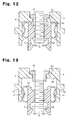
- Fig. 12 is a cross-sectional view taken along line B-B of a fixing portion of the fastening piece 5 in the fastened state
- Figs. 13 and 14 are cross-sectional views taken along line B-B of the fixing portion of the fastening piece 5 in the tentatively assembled state.
- the bolt 16 is first rotated in the loosening direction.
- the nut 15 is fixed to the frame 4.
- the bolt 16 moves away from the frame 4 (downward in Fig. 12 ).
- a contact surface 16a of the bolt 16 comes in contact with engagement portions 5j and 5k arranged on the fastening piece 5.
- the fastening piece 5 also moves together with the bolt 16 so that the contact surface 5c of the fastening piece 5 becomes spaced from the contact surface 4d of the frame 4. Then, the fastening piece 5 is moved to the position at which the fastening piece 5 is in the tentatively assembled state shown in Fig.
- the fastening piece 5 is in the fastened state.
- the handle grip 3 is gripped and pulled outwards of the door 8.
- the support portion 4c of the frame 4 and the support portions 5a and 5b of the fastening piece 5 pivotally support the pivot shaft 3a of the handle grip 3.
- the handle grip 3 starts pivoting about the pivot shaft 3a without becoming loose in the longitudinal direction of the handle grip 3.
- the interlocked portion 3b of the handle grip 3 actuates the bell crank arm 14, and the bell crank arm 14 drives the latch mechanism of the door lock mechanism.
- the door lock mechanism is unlocked. This enables the door 8 to open and move in the opening direction.
- the two support portions 5a and 5b of the fastening piece 5 restrict movement of the pivot shaft 3a in the longitudinal direction in the above embodiments.
- just one of the support portions 5a and 5b may be arranged on the fastening piece 5, and the other one of the support portions may be arranged on the frame 4.
- the fastening piece 5 is held in a tentatively assembled state by the frame 4 through the engagement of the projections 4i and 4j of the frame 4 with the temporary attachment recesses 5f and 5g of the fastening piece 5 in the above embodiment, the fastening piece 5 may be supported in the tentatively assembled state using a separate member.
- the fastening piece 5 may be fixed through another fastening method.
- an engagement hook arranged on the fastening piece 5 may be engaged with the frame 4 (refer to the guide portions 50b in Fig. 5 ).
- a female screw portion corresponding to the nut 15 may be arranged directly on the frame 4.
- a vehicle door handle device according to a fourth embodiment of the present invention will now be described.
- a door handle device 411 for a vehicle includes a guide member 85 fixed to a frame 4.
- the frame 4 is made of a material having high strength, such as a resin containing glass fibers, to support a handle grip 3.
- the guide member 85 is arranged in the vicinity of an opening 4b of the frame 4, and is fixed to the frame 4.
- the guide member 85 is configured to restrict movement of the handle grip 3 in the axial direction of a pivot shaft 3a by sliding a leg portion 3e of the handle grip 3 when the handle grip 3 is pivoted.
- the guide member 85 is made of a material having superior sliding characteristics.
- the guide member 85 is made of a material having hardness that is lower than the material for the frame 4.
- Fig. 16 is a perspective view showing the guide member 85
- Fig. 17 is a perspective view showing the leg portion 3e of the handle grip 3
- Fig. 18 is a cross-sectional view of the vehicle door handle device 411 taken along line C-C of Fig. 15
- Fig. 19 is a partially enlarged view showing the main part of Fig. 18.
- Fig. 18(a) is a cross-sectional view of the handle grip 3 taken at a non-operation position
- Fig. 18(b) is a cross-sectional view of the handle grip 3 taken at a pivot end position in the opening operation direction.
- the guide member 85 which has a substantially U-shaped outer form, has guide portions 85a and 85b facing each other formed on a pair of opposing inner surfaces.
- the guide portions 85a and 85b are formed as projections.
- the guide portions 85a and 85b restrict movement of the handle grip 3 in the axial direction of the pivot shaft 3a (direction indicated by a solid line in Fig. 18 ) by sliding along slide portions 3g and 3h of the leg portion 3e of the handle grip 3.
- the distance D between the vertex of the guide portion 85a and the vertex of the guide portion 85b when the handle grip 3 is separated from the guide member 85 (refer to Fig. 19 ) is set to be smaller than the distance d between the slide portion 3g and the slide portion 3h of the leg portion 3e.
- hollow portions 85c and 85d are respectively arranged on the rear surfaces of the guide portions 85a and 85b to enable the guide portions 85a and 85b to be easily and elastically deformed outwards.
- the guide portions 85a and 85b of the guide member 85 elastically support the leg portion 3e of the handle grip 3 in between and prevents the handle grip 3 from becoming loose in the axial direction of the pivot shaft 3a.
- the guide member 85 is configured to restrict the pivot range of the handle grip 3 in the opening operation direction.
- Contact portions 3i and 3j are arranged on the distal end of the leg portion 3e of the handle grip 3, and stopper portions 85e and 85f are arranged on the guide member 85.
- the contact portions 3i and 3j of the handle grip 3 come in contact with the stopper portions 85e and 85f of the guide member 85 at the pivot end position of the handle grip 3 in the opening operation direction to restrict the pivot range of the handle grip 3.
- Hollow portions 85g and 85h are arranged on the rear side (upper side in Fig.
- the handle grip 3 To open the vehicle door when the vehicle door is in the closed state, the handle grip 3 is gripped and pulled outwards of the vehicle door. Then, the handle grip 3 starts pivoting about the pivot shaft 3a, and the slide portions 3g and 3h of the handle grip 3 start moving while sliding along the guide portions 85a and 85b of the guide member 85 ( Fig. 18(a) ). As the handle grip 3 pivots, the interlocked portion 3b of the handle grip 3 actuates the bell crank arm 14, and the bell crank arm 14 drives the latch mechanism of the door lock mechanism. When the handle grip 3 is pivoted by a first predetermined angle, the door lock mechanism is unlocked. This enables to door to open.
- the handle grip 3 is formed to rotate in the opening operation direction even after the door lock mechanism is unlocked.
- the contact portions 3i and 3j of the handle grip 3 come in contact with the stopper portions 85e and 85f of the guide member 85 when the handle grip 3 rotates by a second predetermined angle ( Fig. 18(b) ). This restricts the range of rotation of the handle grip 3 in the opening operation direction.
- the handle grip 3 is a grip type door handle in the above embodiment, the handle grip 3 may be a flap type door handle.
- the guide member 85 has the two stopper portions 85e and 85f in the above embodiment, the guide member 85 may have one stopper portion or three or more stopper portions.
- the guide member 85 is made of a material having a lower hardness than the material for the frame 4 in the above embodiment, the materials for the guide member 85 and the frame 4 may be selected without considering hardness of the materials.
- gaps may be formed between the guide portions 85a and 85b and the slide portions 3g and 3h.
Claims (16)
- Dispositif de poignée de porte de véhicule destiné à être monté sur un panneau de porte de véhicule (2) ayant des surfaces avant et arrière, le dispositif de poignée de porte de véhicule comprenant :un élément de base (4, 12) pouvant être fixé à la surface arrière du panneau de porte (2) et un élément de préhension (3, 11) agencé sur l'élément de base (4, 12) à partir de la surface avant du panneau de porte (2) de sorte que l'élément de préhension (3, 11) est supporté sur l'élément de base (4, 12) d'une manière inclinable ;un arbre de pivot (3a, 31a, 31a') agencé sur l'élément de préhension (3, 11) ; etun élément de support d'arbre (5, 40, 40') ayant un évidement de support d'arbre (5a, 5b, 40a) pour supporter l'arbre de pivot (3a, 31a, 31a') d'une manière pivotante par rapport à l'élément de base (4, 12) ;le dispositif de poignée de porte de véhicule étant caractérisé en ce qu'il comprend :un élément de fixation (16, 42), l'élément de fixation (16, 42) assemblant l'élément de base (4, 12) et l'élément de support d'arbre (5, 40, 40') ensemble à proximité de l'évidement de support d'arbre (5a, 5b, 40a),l'élément de fixation (16, 42), lorsqu'il est éloigné de l'élément de base (4, 12), met en prise l'élément de support d'arbre (5, 40, 40') pour éloigner l'élément de support d'arbre (5, 40, 40') de l'élément de base (4, 12) afin de créer un espace entre l'élément de support d'arbre (5, 40, 40') et l'élément de base (4, 12), dans lequel état, l'arbre de pivot (3a, 31a, 31a') n'est pas supporté par l'évidement de support d'arbre (5a, 5b, 40a), etl'élément de fixation (16, 42), lorsqu'il est déplacé vers l'élément de base (4, 12), met en prise l'élément de support d'arbre (5, 40, 40') pour maintenir l'élément de support d'arbre (5, 40, 40') sur l'élément de base (4, 12) afin de limiter le mouvement de l'arbre de pivot (3a, 31a, 31a') par l'évidement de support d'arbre (5a, 5b, 40a),dans lequel l'élément de support d'arbre (5, 40, 40') limite le mouvement de l'arbre de pivot (3a, 31a, 31a') dans une direction longitudinale de l'élément de préhension (3, 11) par rapport à l'élément de base (4, 12) lorsque l'élément de fixation (16, 42) est fixé.
- Dispositif de poignée de porte de véhicule selon la revendication 1, caractérisé en ce que :l'élément de préhension (3) comprend un bras de support (31, 3d) ayant une paire de parois opposées (31b) se faisant face, l'arbre de pivot (3a) est agencé sur le bras de support (31, 3d) pour raccorder les parois opposées (31b) entre elles, et l'élément de support d'arbre (5) est logé entre les parois opposées (31b).
- Dispositif de poignée de porte de véhicule selon la revendication 1 ou 2, caractérisé en ce que :une partie flexible (40d) pouvant entrer en contact avec l'arbre de pivot (31a) est formée sur une paroi interne (41a, 42a, 43a) de l'évidement de support d'arbre (40a).
- Dispositif de poignée de porte de véhicule selon la revendication 3, caractérisé en ce que :l'élément de support d'arbre (40) a un trou débouchant (40c) s'étendant autour de l'évidement de support d'arbre (40a) dans la même direction que la direction dans laquelle s'étend l'arbre de pivot (31a),dans lequel une partie de l'élément de support d'arbre (40) entre le trou débouchant (40c) et la paroi interne (41a, 42a, 43a) de l'évidement de support d'arbre (40a) forme la partie flexible (40d).
- Dispositif de poignée de porte de véhicule selon l'une quelconque des revendications 3 ou 4, caractérisé en ce que :l'évidement de support d'arbre (40a) est défini par trois parois internes (41a, 42a, 43a), et la partie flexible (40d) est formée sur au moins l'une des trois parois internes (41a, 42a, 43a).
- Dispositif de poignée de porte de véhicule selon l'une quelconque des revendications 1 à 5, caractérisé en ce que :l'élément de base (12) a un évidement de support d'arbre pour supporter de manière pivotante l'arbre de pivot (31a').
- Dispositif de poignée de porte de véhicule selon l'une quelconque des revendications 1 à 6, caractérisé en ce que :l'arbre de pivot (3a) est cylindrique et s'étend dans une direction perpendiculaire à la direction longitudinale (L) de l'élément de préhension (3).
- Dispositif de poignée de porte de véhicule selon l'une quelconque des revendications 1 à 7, étant en outre caractérisé en ce que :l'élément de fixation (16) est prévu au niveau de l'élément de support d'arbre (5) et raccordé à l'élément de base (4) de sorte que lorsque l'élément de fixation (16) est actionné dans une première direction,l'élément de support d'arbre (5) est amené en mise en prise avec l'élément de base (4) et lorsque l'élément de fixation (16) est actionné dans une seconde direction,l'élément de support d'arbre (5) est dégagé de l'élément de base (4).
- Dispositif de poignée de porte de véhicule selon la revendication 8, caractérisé en ce que :l'un (4) parmi l'élément de base (4) et l'élément de support d'arbre (5) comprend une saillie (4i, 4j) et l'autre (5) parmi l'élément de base (4) et l'élément de support d'arbre (5) a une paroi définissant un évidement de fixation temporaire (5f, 5g), lorsque la saillie (4i, 4j) est mise en prise avec l'évidement de fixation temporaire (5f, 5g) de sorte que l'élément de base (4) maintient l'élément de support d'arbre (5) dans un état provisoirement assemblé qui est la première position, et la paroi définissant l'évidement de fixation temporaire (5f, 5g) est élastiquement déformable.
- Dispositif de poignée de porte de véhicule selon la revendication 8 ou 9, caractérisé en ce que :l'élément de support d'arbre (5) a une partie de mise en prise (5j, 5k) pouvant se mettre en prise avec l'élément de fixation (16) pour limiter la séparation de l'élément de fixation (16) de l'élément de support d'arbre (5).
- Dispositif de poignée de porte de véhicule selon la revendication 10, caractérisé en ce que :l'élément de fixation (16) est un élément de vis mâle (16), et l'élément de base (4) a une partie de vis femelle (15) fixée avec l'élément de vis mâle (16), dans lequel lorsque l'on déplace l'élément de fixation (16) tout en desserrant l'élément de fixation (16), l'élément de fixation (16) est mis en prise avec la partie de fixation (5j, 5k) de sorte que l'élément de support d'arbre (5) se déplace conjointement avec l'élément de fixation (16) vers une position correspondant à l'état provisoirement assemblé.
- Dispositif de poignée de porte de véhicule selon la revendication 11, caractérisé en ce que :l'élément de vis mâle (16) et la partie de vis femelle (15) peuvent se dégager lorsque l'élément de support d'arbre (5) est fixé de manière temporaire à l'élément de base (4).
- Dispositif de poignée de porte de véhicule selon l'une quelconque des revendications 1 à 12, caractérisé en ce qu'il comprend :un élément de guidage (85) fixé à l'élément de base (4), dans lequel l'élément de guidage (85) guide l'élément de préhension (3) de sorte que l'élément de préhension (3) coulisse lorsqu'il est pivoté et limite le mouvement de l'élément de préhension (3) dans une direction axiale de l'arbre de pivot (3a), et l'élément de guidage (85) comprend une partie de butée (85e, 85f), qui vient élastiquement en contact avec l'élément de préhension (3) et limite le pivotement supplémentaire de l'élément de préhension (3), lorsque l'élément de préhension (3) est pivoté dans une position d'extrémité de pivot dans une direction dans laquelle la porte du véhicule s'ouvre.
- Dispositif de poignée de porte de véhicule selon la revendication 13, caractérisé en ce que :l'élément de guidage (85) maintient élastiquement l'élément de préhension (3) pour limiter le mouvement de l'élément de préhension (3) dans la direction axiale de l'arbre de pivot (3a).
- Dispositif de poignée de porte de véhicule selon les revendications 13 ou 14, caractérisé en ce que :l'élément de guidage (85) est réalisé avec un matériau ayant une dureté inférieure à un matériau pour l'élément de base (4).
- Dispositif de poignée de porte de véhicule selon l'une quelconque des revendications 14 à 15, caractérisé en ce que :l'élément de préhension (3) a une première extrémité et une seconde extrémité, et l'arbre de pivot (3a) est agencé sur la première extrémité, et une partie verrouillée (3b) verrouillée avec le mécanisme de verrou de porte et une partie de contact (3i, 3j) qui vient en contact avec la partie de butée (85e, 85f) au niveau de la position d'extrémité de pivot sont agencées sur la seconde extrémité.
Applications Claiming Priority (4)
| Application Number | Priority Date | Filing Date | Title |
|---|---|---|---|
| JP2004215184A JP4469241B2 (ja) | 2004-07-23 | 2004-07-23 | 車両用ドアハンドル装置 |
| JP2005185047 | 2005-06-24 | ||
| JP2005187069A JP4569403B2 (ja) | 2005-06-27 | 2005-06-27 | 車両用ドアハンドル装置 |
| PCT/JP2005/013382 WO2006009205A1 (fr) | 2004-07-23 | 2005-07-21 | Dispositif de poignée de porte pour véhicule |
Publications (3)
| Publication Number | Publication Date |
|---|---|
| EP1797960A1 EP1797960A1 (fr) | 2007-06-20 |
| EP1797960A4 EP1797960A4 (fr) | 2013-03-06 |
| EP1797960B1 true EP1797960B1 (fr) | 2014-10-15 |
Family
ID=35785313
Family Applications (1)
| Application Number | Title | Priority Date | Filing Date |
|---|---|---|---|
| EP20050762033 Expired - Fee Related EP1797960B1 (fr) | 2004-07-23 | 2005-07-21 | Poignee de porte pour vehicule |
Country Status (3)
| Country | Link |
|---|---|
| US (1) | US7971913B2 (fr) |
| EP (1) | EP1797960B1 (fr) |
| WO (1) | WO2006009205A1 (fr) |
Families Citing this family (28)
| Publication number | Priority date | Publication date | Assignee | Title |
|---|---|---|---|---|
| EP1783305B1 (fr) * | 2004-08-05 | 2015-04-22 | Aisin Seiki Kabushiki Kaisha | Dispositif de poignée de porte |
| JP4540119B2 (ja) * | 2006-07-04 | 2010-09-08 | サカエ理研工業株式会社 | 車両用ドアハンドル装置 |
| JP4835324B2 (ja) * | 2006-08-25 | 2011-12-14 | アイシン精機株式会社 | 車両用ドアハンドル装置 |
| IT1395117B1 (it) * | 2009-07-29 | 2012-09-05 | Valeo Spa | Procedimento di assemblaggio di una maniglia in una porta di un autoveicolo e relativa maniglia di porta |
| JP5407652B2 (ja) * | 2009-08-18 | 2014-02-05 | アイシン精機株式会社 | 車両用ドアハンドル装置 |
| JP5153742B2 (ja) * | 2009-08-19 | 2013-02-27 | 株式会社ホンダロック | 車両用ドアのアウトハンドル装置 |
| JP5849460B2 (ja) * | 2010-09-28 | 2016-01-27 | アイシン精機株式会社 | 車両のドアアウタハンドル構造 |
| JP2012092636A (ja) * | 2010-09-30 | 2012-05-17 | Aisin Seiki Co Ltd | 車両用ドアハンドル装置 |
| US9812684B2 (en) | 2010-11-09 | 2017-11-07 | GM Global Technology Operations LLC | Using elastic averaging for alignment of battery stack, fuel cell stack, or other vehicle assembly |
| JP5932609B2 (ja) * | 2012-11-08 | 2016-06-08 | 株式会社ホンダロック | 車両用ドアのアウトハンドル装置 |
| US9605451B2 (en) | 2013-03-14 | 2017-03-28 | Ford Global Technologies, Llc | Wobble free exterior handle design |
| US9863454B2 (en) | 2013-08-07 | 2018-01-09 | GM Global Technology Operations LLC | Alignment system for providing precise alignment and retention of components of a sealable compartment |
| US20150078805A1 (en) * | 2013-09-19 | 2015-03-19 | GM Global Technology Operations LLC | Elastically averaged alignment systems and methods |
| US9511802B2 (en) | 2013-10-03 | 2016-12-06 | GM Global Technology Operations LLC | Elastically averaged alignment systems and methods |
| US9669774B2 (en) | 2013-10-11 | 2017-06-06 | GM Global Technology Operations LLC | Reconfigurable vehicle interior assembly |
| US11280117B2 (en) | 2014-02-28 | 2022-03-22 | Huf Hülsbeck & Fürst Gmbh & Co. Kg | Door-handle system for vehicles |
| US9657807B2 (en) | 2014-04-23 | 2017-05-23 | GM Global Technology Operations LLC | System for elastically averaging assembly of components |
| JP6413438B2 (ja) * | 2014-07-30 | 2018-10-31 | アイシン精機株式会社 | 車両用ドアハンドル装置 |
| US9758110B2 (en) | 2015-01-12 | 2017-09-12 | GM Global Technology Operations LLC | Coupling system |
| DE102015110531A1 (de) * | 2015-06-30 | 2017-01-05 | Huf Hülsbeck & Fürst Gmbh & Co. Kg | Türgriffsystem für Fahrzeuge |
| JP6304209B2 (ja) * | 2015-11-30 | 2018-04-04 | アイシン精機株式会社 | 車両用ハンドル装置 |
| DE102016110754A1 (de) * | 2016-06-10 | 2017-12-14 | Huf Hülsbeck & Fürst Gmbh & Co. Kg | Befestigungsvorrichtung zum Befestigen eines ersten Bauteils an einem zweiten Bauteil |
| US10781617B2 (en) * | 2017-08-10 | 2020-09-22 | Novares Us Llc | Vehicular door handle assembly and method for assembling the same |
| DE102017119580B3 (de) * | 2017-08-25 | 2018-10-11 | Illinois Tool Works Inc. | Betätigungsvorrichtung für eine Kraftfahrzeugtüre mit Einrichtung zur Verminderung des Querspiels eines Flush-Door-Handles mit erweiterten Einsatzmöglichkeiten |
| JP6605636B2 (ja) * | 2018-01-26 | 2019-11-13 | 株式会社ホンダロック | 車両用ドアのアウトハンドル装置 |
| US10457183B2 (en) * | 2018-01-31 | 2019-10-29 | Toyota Motor Engineering & Manufacturing North America, Inc. | Vehicle with a disconnectable handle |
| US11913261B2 (en) * | 2019-02-01 | 2024-02-27 | Nissan North America, Inc. | Vehicle door assembly and mounting structure for a door handle |
| JP7260851B2 (ja) * | 2019-06-06 | 2023-04-19 | 株式会社アイシン | 車両用ドアハンドル装置 |
Family Cites Families (26)
| Publication number | Priority date | Publication date | Assignee | Title |
|---|---|---|---|---|
| AU5579380A (en) * | 1979-03-01 | 1980-09-04 | Itw Ltd. | Adjustable handle mounting |
| JPS57184169A (en) * | 1981-05-06 | 1982-11-12 | Ohi Seisakusho Co Ltd | Inside handle apparatus of automobile door |
| US4475754A (en) * | 1982-05-10 | 1984-10-09 | General Motors Corporation | Pull out door handle assembly |
| JPH0639006Y2 (ja) * | 1986-09-30 | 1994-10-12 | アイシン精機株式会社 | 車両用インサイドハンドル装置 |
| JPH0623656Y2 (ja) * | 1989-01-31 | 1994-06-22 | 株式会社アルファ | 自動車用ドアハンドル装置 |
| JP3319878B2 (ja) * | 1994-06-15 | 2002-09-03 | サカエ理研工業株式会社 | ドアハンドル装置 |
| JPH108786A (ja) * | 1996-06-24 | 1998-01-13 | Alpha Corp | 車両のドアアウトサイドハンドル装置 |
| IT1305155B1 (it) * | 1998-11-03 | 2001-04-10 | Valeo Sicurezza Abitacolo Spa | Maniglia per una porta di un veicolo. |
| JP3468281B2 (ja) * | 1998-12-25 | 2003-11-17 | 株式会社アルファ | 自動車のドアアウトサイドハンドル装置 |
| FR2789712B1 (fr) * | 1999-02-12 | 2001-06-01 | Valeo Securite Habitacle | Poignee d'ouvrant de vehicule automobile comportant un capuchon de verrou |
| FR2802564B1 (fr) * | 1999-12-21 | 2002-02-15 | Valeo Securite Habitacle | Systeme de securite d'un ouvrant de vehicule automobile equipe de commutateurs sans actionnement mecanique |
| JP4427870B2 (ja) | 2000-06-21 | 2010-03-10 | アイシン精機株式会社 | 車両用ドアハンドル装置 |
| US6363577B1 (en) * | 2000-08-25 | 2002-04-02 | Adac Plastics, Inc. | Motor vehicle door handle assembly with maximized bearing interface |
| US6447030B1 (en) * | 2000-08-25 | 2002-09-10 | Adac Plastics, Inc. | Door handle assembly with detented closed position |
| JP3569675B2 (ja) * | 2000-12-14 | 2004-09-22 | 株式会社ユーシン | 自動車用ハンドル装置 |
| JP4552332B2 (ja) | 2001-01-31 | 2010-09-29 | アイシン精機株式会社 | 車両用ドアハンドル装置 |
| US6964439B2 (en) * | 2001-01-11 | 2005-11-15 | Aisin Seiki Kabushiki Kaisha | Vehicle door handle device |
| JP4738650B2 (ja) | 2001-06-26 | 2011-08-03 | サカエ理研工業株式会社 | 車両用ドアハンドル装置 |
| JP3794291B2 (ja) * | 2001-06-29 | 2006-07-05 | スズキ株式会社 | ドアハンドルの組付け構造 |
| US6594861B2 (en) * | 2001-07-20 | 2003-07-22 | Strattec Security Corporation | Motor vehicle door handle apparatus and method of installation |
| JP3619505B2 (ja) * | 2001-11-20 | 2005-02-09 | 株式会社ホンダロック | 車両用ドアのハンドル装置 |
| JP4087656B2 (ja) | 2002-07-25 | 2008-05-21 | 株式会社ユーシン | 車両用ドアハンドル |
| JP4148718B2 (ja) * | 2002-08-06 | 2008-09-10 | サカエ理研工業株式会社 | 車両用ドアハンドル装置 |
| JP2004232300A (ja) * | 2003-01-29 | 2004-08-19 | Aisin Seiki Co Ltd | アウトサイドハンドル装置 |
| US7036857B2 (en) * | 2003-12-22 | 2006-05-02 | Nissan Technical Center North America, Inc. | Vehicle inside door handle assembly |
| JP4835324B2 (ja) * | 2006-08-25 | 2011-12-14 | アイシン精機株式会社 | 車両用ドアハンドル装置 |
-
2005
- 2005-07-21 EP EP20050762033 patent/EP1797960B1/fr not_active Expired - Fee Related
- 2005-07-21 WO PCT/JP2005/013382 patent/WO2006009205A1/fr active Application Filing
- 2005-07-21 US US11/632,827 patent/US7971913B2/en not_active Expired - Fee Related
Also Published As
| Publication number | Publication date |
|---|---|
| EP1797960A1 (fr) | 2007-06-20 |
| WO2006009205A1 (fr) | 2006-01-26 |
| EP1797960A4 (fr) | 2013-03-06 |
| US7971913B2 (en) | 2011-07-05 |
| US20080088139A1 (en) | 2008-04-17 |
Similar Documents
| Publication | Publication Date | Title |
|---|---|---|
| EP1797960B1 (fr) | Poignee de porte pour vehicule | |
| JP3794291B2 (ja) | ドアハンドルの組付け構造 | |
| EP2206859B1 (fr) | Dispositif de poignée de porte de véhicule | |
| WO2006048975A1 (fr) | Mécanisme d'ouverture et de fermeture de porte | |
| WO2013002101A1 (fr) | Dispositif de changement de vitesse et procédé de fabrication pour celui-ci | |
| JP6762986B2 (ja) | 内装用カバー取付構造 | |
| US20050218668A1 (en) | Outside handle for door, having easily bendable portion | |
| JP4569403B2 (ja) | 車両用ドアハンドル装置 | |
| JP4469241B2 (ja) | 車両用ドアハンドル装置 | |
| JP5174131B2 (ja) | 車両用開閉扉の開閉操作装置 | |
| EP1803877B1 (fr) | Structure de poignée de porte nécessitant un espace réduit pour la mise en place d'un mécanisme de relâchement d'un loquet de porte | |
| JP5341474B2 (ja) | 車両用スライドデッキ装置 | |
| US7762608B2 (en) | Vehicle with a trunk | |
| JP4222330B2 (ja) | 便座及び/又は便蓋の取付け構造 | |
| JPH10114352A (ja) | カバー部材のオープンロック機構 | |
| JP2000073630A (ja) | 自動車のドアアウトサイドハンドル装置 | |
| JP4002467B2 (ja) | 車両用ドア | |
| JP5174133B2 (ja) | 車両用開閉扉の開閉操作装置 | |
| JP3969573B2 (ja) | 車両用ドア | |
| JP5330806B2 (ja) | レール用カバー部材、ロアレールに対するレール用カバー部材の取付方法、及び、車両用スライドデッキ装置の組立方法 | |
| JP4432760B2 (ja) | 車両用ドアのアームレスト構造 | |
| JP5603001B2 (ja) | 車両用スライドデッキ装置 | |
| JP2011069089A (ja) | 車輌用のドアハンドル装置 | |
| JP4198934B2 (ja) | 車両用ドア | |
| JP4002468B2 (ja) | 車両用ドア |
Legal Events
| Date | Code | Title | Description |
|---|---|---|---|
| PUAI | Public reference made under article 153(3) epc to a published international application that has entered the european phase |
Free format text: ORIGINAL CODE: 0009012 |
|
| 17P | Request for examination filed |
Effective date: 20070103 |
|
| AK | Designated contracting states |
Kind code of ref document: A1 Designated state(s): DE FR GB TR |
|
| DAX | Request for extension of the european patent (deleted) | ||
| RBV | Designated contracting states (corrected) |
Designated state(s): DE FR GB TR |
|
| A4 | Supplementary search report drawn up and despatched |
Effective date: 20130204 |
|
| RIC1 | Information provided on ipc code assigned before grant |
Ipc: E05B 1/00 20060101AFI20130129BHEP Ipc: E05B 65/20 20060101ALI20130129BHEP |
|
| 17Q | First examination report despatched |
Effective date: 20131105 |
|
| REG | Reference to a national code |
Ref country code: DE Ref legal event code: R079 Ref document number: 602005044935 Country of ref document: DE Free format text: PREVIOUS MAIN CLASS: B05B0001000000 Ipc: E05B0085160000 |
|
| RIC1 | Information provided on ipc code assigned before grant |
Ipc: E05B 85/16 20140101AFI20140307BHEP Ipc: E05B 77/36 20140101ALN20140307BHEP Ipc: E05B 79/06 20140101ALN20140307BHEP |
|
| GRAP | Despatch of communication of intention to grant a patent |
Free format text: ORIGINAL CODE: EPIDOSNIGR1 |
|
| INTG | Intention to grant announced |
Effective date: 20140508 |
|
| GRAS | Grant fee paid |
Free format text: ORIGINAL CODE: EPIDOSNIGR3 |
|
| GRAA | (expected) grant |
Free format text: ORIGINAL CODE: 0009210 |
|
| AK | Designated contracting states |
Kind code of ref document: B1 Designated state(s): DE FR GB TR |
|
| REG | Reference to a national code |
Ref country code: GB Ref legal event code: FG4D |
|
| REG | Reference to a national code |
Ref country code: DE Ref legal event code: R096 Ref document number: 602005044935 Country of ref document: DE Effective date: 20141127 |
|
| REG | Reference to a national code |
Ref country code: DE Ref legal event code: R097 Ref document number: 602005044935 Country of ref document: DE |
|
| PLBE | No opposition filed within time limit |
Free format text: ORIGINAL CODE: 0009261 |
|
| STAA | Information on the status of an ep patent application or granted ep patent |
Free format text: STATUS: NO OPPOSITION FILED WITHIN TIME LIMIT |
|
| 26N | No opposition filed |
Effective date: 20150716 |
|
| REG | Reference to a national code |
Ref country code: FR Ref legal event code: PLFP Year of fee payment: 12 |
|
| REG | Reference to a national code |
Ref country code: FR Ref legal event code: PLFP Year of fee payment: 13 |
|
| PG25 | Lapsed in a contracting state [announced via postgrant information from national office to epo] |
Ref country code: TR Free format text: LAPSE BECAUSE OF FAILURE TO SUBMIT A TRANSLATION OF THE DESCRIPTION OR TO PAY THE FEE WITHIN THE PRESCRIBED TIME-LIMIT Effective date: 20141015 |
|
| REG | Reference to a national code |
Ref country code: FR Ref legal event code: PLFP Year of fee payment: 14 |
|
| PGFP | Annual fee paid to national office [announced via postgrant information from national office to epo] |
Ref country code: FR Payment date: 20190619 Year of fee payment: 15 |
|
| PGFP | Annual fee paid to national office [announced via postgrant information from national office to epo] |
Ref country code: DE Payment date: 20190710 Year of fee payment: 15 |
|
| PGFP | Annual fee paid to national office [announced via postgrant information from national office to epo] |
Ref country code: GB Payment date: 20190717 Year of fee payment: 15 |
|
| REG | Reference to a national code |
Ref country code: DE Ref legal event code: R119 Ref document number: 602005044935 Country of ref document: DE |
|
| GBPC | Gb: european patent ceased through non-payment of renewal fee |
Effective date: 20200721 |
|
| PG25 | Lapsed in a contracting state [announced via postgrant information from national office to epo] |
Ref country code: GB Free format text: LAPSE BECAUSE OF NON-PAYMENT OF DUE FEES Effective date: 20200721 Ref country code: FR Free format text: LAPSE BECAUSE OF NON-PAYMENT OF DUE FEES Effective date: 20200731 |
|
| PG25 | Lapsed in a contracting state [announced via postgrant information from national office to epo] |
Ref country code: DE Free format text: LAPSE BECAUSE OF NON-PAYMENT OF DUE FEES Effective date: 20210202 |