EP1736231B2 - Vorrichtung und verfahren zur gewinnung von co2 - Google Patents
Vorrichtung und verfahren zur gewinnung von co2 Download PDFInfo
- Publication number
- EP1736231B2 EP1736231B2 EP05720741.7A EP05720741A EP1736231B2 EP 1736231 B2 EP1736231 B2 EP 1736231B2 EP 05720741 A EP05720741 A EP 05720741A EP 1736231 B2 EP1736231 B2 EP 1736231B2
- Authority
- EP
- European Patent Office
- Prior art keywords
- solution
- lean
- rich
- regeneration tower
- supply line
- Prior art date
- Legal status (The legal status is an assumption and is not a legal conclusion. Google has not performed a legal analysis and makes no representation as to the accuracy of the status listed.)
- Active
Links
- 238000000034 method Methods 0.000 title description 17
- 230000008929 regeneration Effects 0.000 claims description 219
- 238000011069 regeneration method Methods 0.000 claims description 219
- 238000011084 recovery Methods 0.000 claims description 88
- 238000010521 absorption reaction Methods 0.000 claims description 44
- 239000000284 extract Substances 0.000 claims description 11
- 229920006395 saturated elastomer Polymers 0.000 claims description 5
- 230000000052 comparative effect Effects 0.000 description 63
- 230000000694 effects Effects 0.000 description 16
- 238000000605 extraction Methods 0.000 description 9
- 238000011049 filling Methods 0.000 description 7
- 238000002485 combustion reaction Methods 0.000 description 6
- 238000010438 heat treatment Methods 0.000 description 5
- 238000010992 reflux Methods 0.000 description 4
- HZAXFHJVJLSVMW-UHFFFAOYSA-N 2-Aminoethan-1-ol Chemical compound NCCO HZAXFHJVJLSVMW-UHFFFAOYSA-N 0.000 description 3
- 238000006243 chemical reaction Methods 0.000 description 3
- 230000001172 regenerating effect Effects 0.000 description 3
- 238000011144 upstream manufacturing Methods 0.000 description 3
- BFSVOASYOCHEOV-UHFFFAOYSA-N 2-diethylaminoethanol Chemical compound CCN(CC)CCO BFSVOASYOCHEOV-UHFFFAOYSA-N 0.000 description 2
- 230000001476 alcoholic effect Effects 0.000 description 2
- 150000001412 amines Chemical class 0.000 description 2
- 238000001816 cooling Methods 0.000 description 2
- 230000003247 decreasing effect Effects 0.000 description 2
- 239000002803 fossil fuel Substances 0.000 description 2
- 125000002887 hydroxy group Chemical group [H]O* 0.000 description 2
- XLYOFNOQVPJJNP-UHFFFAOYSA-N water Substances O XLYOFNOQVPJJNP-UHFFFAOYSA-N 0.000 description 2
- GIAFURWZWWWBQT-UHFFFAOYSA-N 2-(2-aminoethoxy)ethanol Chemical compound NCCOCCO GIAFURWZWWWBQT-UHFFFAOYSA-N 0.000 description 1
- MIJDSYMOBYNHOT-UHFFFAOYSA-N 2-(ethylamino)ethanol Chemical compound CCNCCO MIJDSYMOBYNHOT-UHFFFAOYSA-N 0.000 description 1
- 229940058020 2-amino-2-methyl-1-propanol Drugs 0.000 description 1
- OPKOKAMJFNKNAS-UHFFFAOYSA-N N-methylethanolamine Chemical compound CNCCO OPKOKAMJFNKNAS-UHFFFAOYSA-N 0.000 description 1
- GSEJCLTVZPLZKY-UHFFFAOYSA-N Triethanolamine Chemical compound OCCN(CCO)CCO GSEJCLTVZPLZKY-UHFFFAOYSA-N 0.000 description 1
- 125000003277 amino group Chemical group 0.000 description 1
- CBTVGIZVANVGBH-UHFFFAOYSA-N aminomethyl propanol Chemical compound CC(C)(N)CO CBTVGIZVANVGBH-UHFFFAOYSA-N 0.000 description 1
- 238000007796 conventional method Methods 0.000 description 1
- 230000007850 degeneration Effects 0.000 description 1
- ZBCBWPMODOFKDW-UHFFFAOYSA-N diethanolamine Chemical compound OCCNCCO ZBCBWPMODOFKDW-UHFFFAOYSA-N 0.000 description 1
- LVTYICIALWPMFW-UHFFFAOYSA-N diisopropanolamine Chemical compound CC(O)CNCC(C)O LVTYICIALWPMFW-UHFFFAOYSA-N 0.000 description 1
- 229940043276 diisopropanolamine Drugs 0.000 description 1
- CRVGTESFCCXCTH-UHFFFAOYSA-N methyl diethanolamine Chemical compound OCCN(C)CCO CRVGTESFCCXCTH-UHFFFAOYSA-N 0.000 description 1
- 238000010248 power generation Methods 0.000 description 1
- 238000010792 warming Methods 0.000 description 1
Images


Classifications
-
- B—PERFORMING OPERATIONS; TRANSPORTING
- B01—PHYSICAL OR CHEMICAL PROCESSES OR APPARATUS IN GENERAL
- B01D—SEPARATION
- B01D53/00—Separation of gases or vapours; Recovering vapours of volatile solvents from gases; Chemical or biological purification of waste gases, e.g. engine exhaust gases, smoke, fumes, flue gases, aerosols
- B01D53/14—Separation of gases or vapours; Recovering vapours of volatile solvents from gases; Chemical or biological purification of waste gases, e.g. engine exhaust gases, smoke, fumes, flue gases, aerosols by absorption
- B01D53/1425—Regeneration of liquid absorbents
-
- B—PERFORMING OPERATIONS; TRANSPORTING
- B01—PHYSICAL OR CHEMICAL PROCESSES OR APPARATUS IN GENERAL
- B01D—SEPARATION
- B01D53/00—Separation of gases or vapours; Recovering vapours of volatile solvents from gases; Chemical or biological purification of waste gases, e.g. engine exhaust gases, smoke, fumes, flue gases, aerosols
- B01D53/14—Separation of gases or vapours; Recovering vapours of volatile solvents from gases; Chemical or biological purification of waste gases, e.g. engine exhaust gases, smoke, fumes, flue gases, aerosols by absorption
- B01D53/1456—Removing acid components
- B01D53/1475—Removing carbon dioxide
-
- B—PERFORMING OPERATIONS; TRANSPORTING
- B01—PHYSICAL OR CHEMICAL PROCESSES OR APPARATUS IN GENERAL
- B01D—SEPARATION
- B01D53/00—Separation of gases or vapours; Recovering vapours of volatile solvents from gases; Chemical or biological purification of waste gases, e.g. engine exhaust gases, smoke, fumes, flue gases, aerosols
- B01D53/34—Chemical or biological purification of waste gases
- B01D53/46—Removing components of defined structure
- B01D53/62—Carbon oxides
-
- B—PERFORMING OPERATIONS; TRANSPORTING
- B01—PHYSICAL OR CHEMICAL PROCESSES OR APPARATUS IN GENERAL
- B01D—SEPARATION
- B01D2258/00—Sources of waste gases
- B01D2258/02—Other waste gases
- B01D2258/0283—Flue gases
-
- B—PERFORMING OPERATIONS; TRANSPORTING
- B01—PHYSICAL OR CHEMICAL PROCESSES OR APPARATUS IN GENERAL
- B01D—SEPARATION
- B01D2259/00—Type of treatment
- B01D2259/65—Employing advanced heat integration, e.g. Pinch technology
-
- Y—GENERAL TAGGING OF NEW TECHNOLOGICAL DEVELOPMENTS; GENERAL TAGGING OF CROSS-SECTIONAL TECHNOLOGIES SPANNING OVER SEVERAL SECTIONS OF THE IPC; TECHNICAL SUBJECTS COVERED BY FORMER USPC CROSS-REFERENCE ART COLLECTIONS [XRACs] AND DIGESTS
- Y02—TECHNOLOGIES OR APPLICATIONS FOR MITIGATION OR ADAPTATION AGAINST CLIMATE CHANGE
- Y02C—CAPTURE, STORAGE, SEQUESTRATION OR DISPOSAL OF GREENHOUSE GASES [GHG]
- Y02C20/00—Capture or disposal of greenhouse gases
- Y02C20/40—Capture or disposal of greenhouse gases of CO2
Definitions
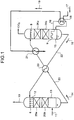
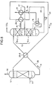
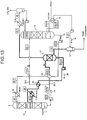
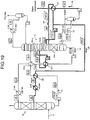
- the lean solution 16 being the regenerated solution is supplied from the regeneration tower 15 to the absorption tower 13 through a lean-solution supply line 22.
- a lean-solution heat exchanger 23 which heats the rich solution 14 with residual heat of the lean solution 16, is provided in the rich-solution supply line 20.
- reference numeral 8 represents a nozzle, 9 a chimney tray, 10 CO 2 -removed exhaust gas, 25a and 25b filling layers provided in the absorption tower 13, and 26a and 26b filling layers provided in the regeneration tower 15.
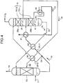
- the steam-condensate heat exchanger 21 heats the rich solution 14 with the residual heat of the steam condensate 19 fed from the regeneration heater 18, in which the rich solution is heated with the residual heat of the steam condensate, therefore, the residual heat of the steam condensate 19 having been used in the regeneration heater 18 is effectively used.
- the rich solution 14 heated with the residual heat is introduced into the flash drum 27. Then, the rich solution 14 is caused to flash in the flash drum 27 to enable improvement of CO 2 removal efficiency.
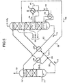
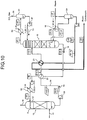
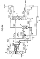
- Fig. 3 is a schematic of a CO 2 recovery system according to a second comparative embodiment. Components the same as those in each of the CO 2 recovery systems according to the first and the first comparative embodiments are assigned with the same reference numerals, and explanation thereof is omitted. As shown in Fig.
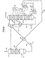
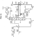
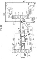
- FIG. 15 is a schematic of the CO 2 recovery system according to example 6. Components the same as those of example 1 are assigned with the same reference numerals and explanation thereof is omitted.
- the regeneration tower 15 was divided into two portions, the semi-lean solution 28 extracted from the upper-portion regeneration tower 15-U was heat-exchanged with the residual heat of the steam condensate 19 in the steam-condensate heat exchanger 21, and the semi-lean solution 28 heat-exchanged was returned to the lower-portion regeneration tower 15-L. This caused an increase in the temperature of the semi-lean solution to be supplied to the lower portion side of the regeneration tower 15.
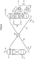
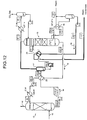
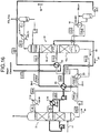
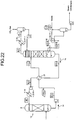
- FIG. 21 is a schematic of the CO 2 recovery system according to example 12. Components the same as those of example 1 are assigned with the same reference numerals and explanation thereof is omitted.
- the regeneration tower 15 was divided into three portions such as the upper-portion regeneration tower 15-U, the middle-portion regeneration tower 15-M, and the lower-portion regeneration tower 15-L.
- the semi-lean solution 28 extracted from the middle-portion regeneration tower 15-M was heat-exchanged with the residual heat of the steam condensate in the steam-condensate heat exchanger 21.
- the rich solution 14 was divided, and the lean-solution heat exchanger 23 was provided in the first rich-solution supply line 20-1.
Landscapes
- Chemical & Material Sciences (AREA)
- Engineering & Computer Science (AREA)
- General Chemical & Material Sciences (AREA)
- Chemical Kinetics & Catalysis (AREA)
- Oil, Petroleum & Natural Gas (AREA)
- Analytical Chemistry (AREA)
- Environmental & Geological Engineering (AREA)
- Health & Medical Sciences (AREA)
- Biomedical Technology (AREA)
- Gas Separation By Absorption (AREA)
- Treating Waste Gases (AREA)
- Electrical Discharge Machining, Electrochemical Machining, And Combined Machining (AREA)
- Purification Treatments By Anaerobic Or Anaerobic And Aerobic Bacteria Or Animals (AREA)
Claims (2)
- CO2-Rückgewinnungssystem, welches einen Absorptionsturm (13), der CO2-haltiges Gas mit einer CO2-absorbierenden Lösung in Kontakt bringt, um CO2 zu entfernen, und einen Regenerationsturm (15), der eine reiche Lösung, die CO2 absorbiert hat, regeneriert, enthält und welches eine magere Lösung, die durch Entfernen von CO2 aus der reichen Lösung in dem Regenerationsturm erhalten wird, in dem Absorptionsturm wiederverwendet und umfasst:eine Regenerationsheizvorrichtung (18), welche die in der Nähe eines unteren Bereichs des Regenerationsturms (15) wiedergewonnene magere Lösung nach außen entnimmt und einen Wärmeaustausch der mageren Lösung mit gesättigtem Dampf durchführt; undeinen Dampf-Kondensat-Wärmetauscher (21), der die reiche Lösung, die dem Regenerationsturm (15) zuzuführen ist, mit der Restwärme des Dampfkondensats, das aus der Regenerationsheizvorrichtung eingespeist wird, erwärmt, das CO2-Rückgewinnungssystem weiterhin umfasst:eine Versorgungsleitung für die reiche Lösung (20), welche die reiche Lösung von dem Absorptionsturm (13) zu dem Regenerationsturm (15) befördert;eine Versorgungsleitung für die magere Lösung (22), welche die magere Lösung dem Regenerationsturm (15) entnimmt und die entnommene magere Lösung zu dem Absorptionsturm (13) befördert; undeinen Wärmetauscher für die magere Lösung (23), der zwischen der Versorgungsleitung für die reiche Lösung (20) und der Versorgungsleitung für die magere Lösung (22) angeordnet ist und die reiche Lösung in der Versorgungsleitung für die reiche Lösung (20) mit Restwärme der mageren Lösung in der Versorgungsleitung für die magere Lösung (22) erwärmt,wobei der Dampf-Kondensat-Wärmetauscher (21) die dem Regenerationsturm (15) zuzuführende reiche Lösung an einer Stelle, die dem Wärmetauscher für die magere Lösung (23) nachgeschaltet ist, erwärmt.
- CO2-Rückgewinnungssystem, welches einen Absorptionsturm (13), der CO2-haltiges Gas mit einer CO2-absorbierenden Lösung in Kontakt bringt, um CO2 zu entfernen, und einen Regenerationsturm (15), der eine reiche Lösung, die CO2 absorbiert hat, regeneriert, enthält und welches eine magere Lösung, die durch Entfernen von CO2 aus der reichen Lösung in dem Regenerationsturm erhalten wird, in dem Absorptionsturm wiederverwendet und umfasst:eine Regenerationsheizvorrichtung (18), welche die in der Nähe eines unteren Bereichs des Regenerationsturms (15) wiedergewonnene magere Lösung nach außen entnimmt und einen Wärmeaustausch der mageren Lösung mit gesättigtem Dampf durchführt; undeinen Dampf-Kondensat-Wärmetauscher (21), der die reiche Lösung, die dem Regenerationsturm (15) zuzuführen ist, mit der Restwärme des Dampfkondensats, das aus der Regenerationsheizvorrichtung eingespeist wird, erwärmt, wobei der Regenerationsturm (15) einen oberen Regenerationsturmbereich (15-U) und einen unteren Regenerationsturmbereich (15-L) enthält und das CO2-Rückgewinnungssystem weiterhin umfasst:eine Versorgungsleitung für die reiche Lösung (20), welche die reiche Lösung von dem Absorptionsturm (13) zu dem Regenerationsturm (15) befördert;einen Verzweigungsknoten (24), der sich in der Versorgungsleitung für die reiche Lösung (20) befindet und der die Versorgungsleitung für die reiche Lösung (20) in eine erste Versorgungsleitung für die reiche Lösung (20-1) und eine zweite Versorgungsleitung für die reiche Lösung (20-2) verzweigt, wobei der Dampf-Kondensat-Wärmetauscher (21) sich in der ersten Versorgungsleitung für die reiche Lösung (20-1) befindet und die reiche Lösung in der ersten Versorgungsleitung für die reiche Lösung (20-1) mit Restwärme des Dampfkondensats erwärmt;eine Versorgungsleitung für die halbmagere Lösung (30), die die halbmagere Lösung aus dem oberen Regenerationsturmbereich (15-U) entnimmt und die entnommene halbmagere Lösung zu einem mittleren Abschnittsbereich des Absorptionsturms (13) befördert;einen Wärmetauscher für die halbmagere Lösung (29), der sich in der zweiten Versorgungsleitung für die reiche Lösung (20-2) und der Versorgungsleitung für die halbmagere Lösung (30) befindet und die reiche Lösung in der zweiten Versorgungsleitung für die reiche Lösung (20-2) mit Restwärme der halbmageren Lösung (28) in der Versorgungsleitung für die halbmagere Lösung (30) erwärmt, undeine Versorgungsleitung für die magere Lösung (22), die die magere Lösung aus dem Regenerationsturm (15) extrahiert und die extrahierte magere Lösung zu dem Absorptionsturm (13) befördert; und einen Wärmetauscher für die magere Lösung (23), der zwischen der ersten Versorgungsleitung für die reiche Lösung (20-1) und der Versorgungsleitung für die magere Lösung (22) angeordnet ist und die reiche Lösung in der erstenVersorgungsleitung für die reiche Lösung (20-1) mit Restwärme der mageren Lösung in der Versorgungsleitung für die magere Lösung (22) erwärmt,wobei der Dampf-Kondensat-Wärmetauscher (21) die dem Regenerationsturm (15) zuzuführende reiche Lösung an einer Stelle, die dem Wärmetauscher für die magere Lösung (23) nachgeschaltet ist, erwärmt,wobeiein Ende der ersten Versorgungsleitung für die reiche Lösung (20-1) mit dem unteren Regenerationsturmbereich (15-L) verbunden ist undein Ende der zweiten Versorgungsleitung für die reiche Lösung (20-2) mit dem oberen Regenerationsturmbereich (15-U) verbunden ist.
Priority Applications (2)
| Application Number | Priority Date | Filing Date | Title |
|---|---|---|---|
| EP18175978.8A EP3409344B1 (de) | 2004-03-15 | 2005-03-14 | Co2-rückgewinnungssystem und -verfahren |
| EP12199653.2A EP2578290B1 (de) | 2004-03-15 | 2005-03-14 | CO2-Rückgewinnungssystem und -verfahren |
Applications Claiming Priority (2)
| Application Number | Priority Date | Filing Date | Title |
|---|---|---|---|
| JP2004073388A JP4690659B2 (ja) | 2004-03-15 | 2004-03-15 | Co2回収装置 |
| PCT/JP2005/004473 WO2005097299A1 (ja) | 2004-03-15 | 2005-03-14 | Co2回収装置及び方法 |
Related Child Applications (5)
| Application Number | Title | Priority Date | Filing Date |
|---|---|---|---|
| EP12199653.2A Division-Into EP2578290B1 (de) | 2004-03-15 | 2005-03-14 | CO2-Rückgewinnungssystem und -verfahren |
| EP12199653.2A Division EP2578290B1 (de) | 2004-03-15 | 2005-03-14 | CO2-Rückgewinnungssystem und -verfahren |
| EP18175978.8A Division EP3409344B1 (de) | 2004-03-15 | 2005-03-14 | Co2-rückgewinnungssystem und -verfahren |
| EP18175978.8A Division-Into EP3409344B1 (de) | 2004-03-15 | 2005-03-14 | Co2-rückgewinnungssystem und -verfahren |
| EP12199653.2 Division-Into | 2012-12-28 |
Publications (4)
| Publication Number | Publication Date |
|---|---|
| EP1736231A1 EP1736231A1 (de) | 2006-12-27 |
| EP1736231A4 EP1736231A4 (de) | 2009-09-23 |
| EP1736231B1 EP1736231B1 (de) | 2013-05-15 |
| EP1736231B2 true EP1736231B2 (de) | 2022-01-05 |
Family
ID=35080469
Family Applications (3)
| Application Number | Title | Priority Date | Filing Date |
|---|---|---|---|
| EP12199653.2A Active EP2578290B1 (de) | 2004-03-15 | 2005-03-14 | CO2-Rückgewinnungssystem und -verfahren |
| EP18175978.8A Active EP3409344B1 (de) | 2004-03-15 | 2005-03-14 | Co2-rückgewinnungssystem und -verfahren |
| EP05720741.7A Active EP1736231B2 (de) | 2004-03-15 | 2005-03-14 | Vorrichtung und verfahren zur gewinnung von co2 |
Family Applications Before (2)
| Application Number | Title | Priority Date | Filing Date |
|---|---|---|---|
| EP12199653.2A Active EP2578290B1 (de) | 2004-03-15 | 2005-03-14 | CO2-Rückgewinnungssystem und -verfahren |
| EP18175978.8A Active EP3409344B1 (de) | 2004-03-15 | 2005-03-14 | Co2-rückgewinnungssystem und -verfahren |
Country Status (8)
| Country | Link |
|---|---|
| US (5) | US7918926B2 (de) |
| EP (3) | EP2578290B1 (de) |
| JP (1) | JP4690659B2 (de) |
| AU (2) | AU2005230300B2 (de) |
| CA (2) | CA2689784C (de) |
| DK (1) | DK1736231T3 (de) |
| NO (1) | NO344753B1 (de) |
| WO (1) | WO2005097299A1 (de) |
Families Citing this family (99)
| Publication number | Priority date | Publication date | Assignee | Title |
|---|---|---|---|---|
| JP4690659B2 (ja) * | 2004-03-15 | 2011-06-01 | 三菱重工業株式会社 | Co2回収装置 |
| JP5021917B2 (ja) * | 2005-09-01 | 2012-09-12 | 三菱重工業株式会社 | Co2回収装置及び方法 |
| WO2007104800A1 (de) † | 2006-03-16 | 2007-09-20 | Basf Se | Verfahren zum inkontaktbringen zweier phasen, deren kontakt von wärmeentwicklung begleitet ist |
| JP5230088B2 (ja) * | 2006-09-06 | 2013-07-10 | 三菱重工業株式会社 | Co2回収装置及び方法 |
| NO333560B1 (no) * | 2006-11-24 | 2013-07-08 | Aker Clean Carbon As | Fremgangsmåte og regenerator for regenerering av flytende CO2 absorbent. |
| US7601315B2 (en) | 2006-12-28 | 2009-10-13 | Cansolv Technologies Inc. | Process for the recovery of carbon dioxide from a gas stream |
| JP2008190950A (ja) * | 2007-02-02 | 2008-08-21 | Horiba Ltd | 試料中の酸化セレン除去方法と除去装置、およびこれを用いた石炭燃焼排気ガス中の水銀測定方法および測定装置 |
| JP5215595B2 (ja) * | 2007-06-18 | 2013-06-19 | 三菱重工業株式会社 | 吸収液、吸収液を用いたco2又はh2s除去装置及び方法 |
| JP2008307520A (ja) * | 2007-06-18 | 2008-12-25 | Mitsubishi Heavy Ind Ltd | Co2又はh2s除去システム、co2又はh2s除去方法 |
| NO336193B1 (no) | 2007-09-14 | 2015-06-08 | Aker Engineering & Technology | Forbedret fremgangsmåte ved regenerering av absorbent |
| DE102007056625B3 (de) * | 2007-11-23 | 2008-09-04 | Lurgi Gmbh | Verfahren zur Behandlung eines CO2 enthaltenden Prozessgasstrom |
| US20090151564A1 (en) * | 2007-12-13 | 2009-06-18 | Alstom Technology Ltd. | System and method for removal of an acidic component from a process stream |
| JP4929227B2 (ja) * | 2008-04-30 | 2012-05-09 | 株式会社日立製作所 | 高湿分空気利用ガスタービンシステム |
| KR100962871B1 (ko) * | 2008-06-10 | 2010-06-09 | 현대자동차주식회사 | 이산화탄소 흡수액 재생방법 |
| WO2009153351A1 (en) | 2008-06-19 | 2009-12-23 | Shell Internationale Research Maatschappij B.V. | Process for the removal of carbon dioxide from a gas |
| JP5558036B2 (ja) | 2008-09-04 | 2014-07-23 | 株式会社東芝 | 二酸化炭素回収型汽力発電システム |
| WO2010043859A1 (en) * | 2008-10-14 | 2010-04-22 | Cyril Timmins | High pressure physical absorption process for use in carbon capture in energy production processes |
| US7785399B2 (en) * | 2009-01-16 | 2010-08-31 | Uop Llc | Heat integration for hot solvent stripping loop in an acid gas removal process |
| CA2750780C (en) * | 2009-01-28 | 2016-12-13 | Siemens Aktiengesellschaft | Method and device for separating of carbon dioxide from an exhaust gas of a fossil-fired power plant |
| JP5396464B2 (ja) * | 2009-03-16 | 2014-01-22 | ジェイパワー・エンテック株式会社 | 乾式排ガス処理装置 |
| WO2010106623A1 (ja) * | 2009-03-16 | 2010-09-23 | ジェイパワー・エンテック株式会社 | 再生塔及び乾式排ガス処理装置 |
| DE102009021319A1 (de) * | 2009-05-14 | 2010-11-18 | Linde-Kca-Dresden Gmbh | Verfahren und Vorrichtung zur Behandlung von Rauchgasen |
| EP2442891A2 (de) * | 2009-06-19 | 2012-04-25 | Shell Internationale Research Maatschappij B.V. | Verfahren zur entfernung von kohlendioxid und/oder schwefelwasserstoff aus einem gas |
| KR101110661B1 (ko) * | 2009-06-30 | 2012-03-13 | 한국전력공사 | 발전설비용 산성가스 분리 시스템 |
| DE102009052640A1 (de) * | 2009-11-10 | 2011-05-12 | Linde-Lkca-Dresden Gmbh | Verfahren und Vorrichtung zur Gaswäsche |
| JP2011240321A (ja) * | 2010-04-20 | 2011-12-01 | Babcock Hitachi Kk | 二酸化炭素除去装置を有する排ガス処理システム |
| EP2383522B1 (de) * | 2010-04-28 | 2016-11-02 | General Electric Technology GmbH | Thermische Integration der Kohlendioxiderfassung und Komprimiervorrichtung mit Dampf- oder kombinierter Zyklusanlage |
| US9919259B2 (en) * | 2010-07-09 | 2018-03-20 | Carbon Capture Scientific, Llc | Gas pressurized separation column and process to generate a high pressure product gas |
| US8425655B2 (en) | 2010-07-09 | 2013-04-23 | Carbon Capture Scientific, Llc | Gas pressurized separation column and process to generate a high pressure product gas |
| JP5586358B2 (ja) * | 2010-07-16 | 2014-09-10 | 株式会社東芝 | 二酸化炭素分離回収システム及びその運転方法 |
| US8728209B2 (en) * | 2010-09-13 | 2014-05-20 | Alstom Technology Ltd | Method and system for reducing energy requirements of a CO2 capture system |
| JP5582960B2 (ja) * | 2010-10-22 | 2014-09-03 | 株式会社東芝 | 二酸化炭素分離回収システム及びリボイラー入熱量測定方法 |
| CN101972599B (zh) * | 2010-10-28 | 2012-05-30 | 绍兴文理学院 | 钙基co2吸收与再生装置 |
| JP5697411B2 (ja) * | 2010-11-17 | 2015-04-08 | 株式会社東芝 | 二酸化炭素回収装置および二酸化炭素回収方法 |
| JP5591083B2 (ja) * | 2010-12-01 | 2014-09-17 | 三菱重工業株式会社 | Co2回収システム |
| JP5737916B2 (ja) | 2010-12-01 | 2015-06-17 | 三菱重工業株式会社 | Co2回収システム |
| JP2012117796A (ja) * | 2010-12-03 | 2012-06-21 | Mitsubishi Heavy Ind Ltd | エネルギー回収装置及び石炭ガス化発電プラント |
| US8845790B2 (en) * | 2011-01-06 | 2014-09-30 | Alstom Technology Ltd | Method and system for removal of gaseous contaminants |
| JP5655593B2 (ja) | 2011-01-27 | 2015-01-21 | 株式会社Ihi | 二酸化炭素の回収方法及び回収装置 |
| JP5398755B2 (ja) * | 2011-02-08 | 2014-01-29 | 株式会社日立製作所 | Co2回収方法およびco2回収装置 |
| US8647421B2 (en) | 2011-03-17 | 2014-02-11 | Mitsubishi Heavy Industries, Ltd. | CO2 recovery apparatus |
| JP5693344B2 (ja) | 2011-04-13 | 2015-04-01 | 三菱重工業株式会社 | Co2回収装置 |
| DE102011050329A1 (de) * | 2011-05-13 | 2012-11-15 | Hitachi Power Europe Gmbh | Verfahren und Vorrichtung zur Abscheidung von CO2 aus einem Rauchgasstrom |
| CN102258928B (zh) * | 2011-05-18 | 2013-12-25 | 成都华西工业气体有限公司 | 溶剂循环吸收法烟气脱硫中脱硫溶剂的加压热再生流程 |
| AU2012267842B2 (en) * | 2011-06-09 | 2016-01-07 | Asahi Kasei Kabushiki Kaisha | Carbon-dioxide absorber and carbon-dioxide separation/recovery method using said absorber |
| US9523499B1 (en) * | 2011-06-14 | 2016-12-20 | U.S. Department Of Energy | Regenerable mixed copper-iron-inert support oxygen carriers for solid fuel chemical looping combustion process |
| US8833081B2 (en) * | 2011-06-29 | 2014-09-16 | Alstom Technology Ltd | Low pressure steam pre-heaters for gas purification systems and processes of use |
| DE102011108308A1 (de) * | 2011-07-25 | 2013-01-31 | Thyssenkrupp Uhde Gmbh | Wärmerückgewinnung bei Absorptions- und Desorptionsprozessen bei reduzierter Wärmeaustauschfläche |
| DE102011108749A1 (de) | 2011-07-28 | 2013-01-31 | Thyssenkrupp Uhde Gmbh | Wärmerückgewinnung bei Absorptions- und Desorptionsprozessen |
| US9259680B2 (en) | 2011-09-06 | 2016-02-16 | Frank Bela | Claus hydrocarbon destruction via staged solvent regeneration |
| JP6172884B2 (ja) | 2011-10-21 | 2017-08-02 | 三菱重工業株式会社 | 3成分吸収液、co2又はh2s又はその双方の除去装置及び方法 |
| JP5821531B2 (ja) * | 2011-10-28 | 2015-11-24 | 株式会社Ihi | 二酸化炭素の回収方法及び回収装置 |
| US9492786B2 (en) * | 2011-11-22 | 2016-11-15 | Fluor Corporation | Multi-purpose absorber |
| RU2540634C1 (ru) * | 2011-12-07 | 2015-02-10 | Альстом Текнолоджи Лтд | Способ и система для удаления газообразных загрязнений |
| FR2986441B1 (fr) * | 2012-02-06 | 2014-08-08 | IFP Energies Nouvelles | Procede de captage de co2 par absorption avec utilisation de vapeur basse temperature et d'un flash pour la regeneration |
| JP5646524B2 (ja) * | 2012-02-27 | 2014-12-24 | 株式会社東芝 | 二酸化炭素分離回収システムおよびその運転方法 |
| JP5959882B2 (ja) * | 2012-03-05 | 2016-08-02 | 三菱日立パワーシステムズ株式会社 | 燃焼排ガス中の二酸化炭素化学吸収システム |
| JP5659176B2 (ja) * | 2012-03-06 | 2015-01-28 | 株式会社東芝 | 二酸化炭素回収装置及び二酸化炭素回収方法 |
| CN102616742A (zh) * | 2012-04-06 | 2012-08-01 | 智胜化工股份有限公司 | 合成氨生产线闪蒸罐减压后mdea富液的富液加热器 |
| JP5966565B2 (ja) * | 2012-04-24 | 2016-08-10 | 株式会社Ihi | 二酸化炭素の回収方法及び回収装置 |
| JP2013226487A (ja) * | 2012-04-24 | 2013-11-07 | Mitsubishi Heavy Ind Ltd | Co2回収装置およびco2回収方法 |
| JP5986796B2 (ja) | 2012-05-11 | 2016-09-06 | 三菱重工業株式会社 | 複合アミン吸収液、co2又はh2s又はその双方の除去装置及び方法 |
| KR101375645B1 (ko) * | 2012-06-12 | 2014-03-19 | 한국전력기술 주식회사 | 재기화기 스팀응축수의 열을 이용한 이산화탄소 포집장치 |
| US20140041523A1 (en) * | 2012-08-09 | 2014-02-13 | Mitsubishi Heavy Industries, Ltd. | Exhaust gas treatment system |
| DE102012107333A1 (de) * | 2012-08-09 | 2014-02-13 | Thyssenkrupp Uhde Gmbh | Verfahren zur Regeneration einer für eine Gaswäsche vorgesehenen und mit aromatischen Kohlenwasserstoffen angereicherten Waschflüssigkeit sowie Regenerationsanordnung |
| DE102012107336A1 (de) * | 2012-08-09 | 2014-02-13 | Thyssenkrupp Uhde Gmbh | Verfahren zur Entfernung von aromatischen Kohlenwasserstoffen aus Kokereigas mit Biodiesel als Waschflüssigkeit und Vorrichtung zur Durchführung des Verfahrens |
| US10195561B2 (en) * | 2012-09-20 | 2019-02-05 | Mitsubishi Heavy Industries Engineering, Ltd. | Steam supply system and CO2 recovery unit including the same |
| US9233337B2 (en) * | 2012-09-20 | 2016-01-12 | Mitsubishi Heavy Industries, Ltd. | CO2 recovery device |
| KR101951047B1 (ko) * | 2012-09-20 | 2019-02-21 | 한국전력공사 | 화학적 흡수제를 이용한 이산화탄소의 흡수 및 탈거 장치 |
| GB201218949D0 (en) * | 2012-10-22 | 2012-12-05 | Bp Alternative Energy Internat Ltd | Separatiion of components from a gas mixture |
| AU2013345340B2 (en) * | 2012-11-14 | 2017-08-24 | Board Of Regents, The University Of Texas System | Apparatus for and method of removing acidic gas from a gaseous stream and regenerating an absorbent solution |
| EP2767325A1 (de) * | 2013-02-14 | 2014-08-20 | Shell Internationale Research Maatschappij B.V. | Verfahren zur Entfernung von Kohlendioxid aus einem Gas |
| JP5995746B2 (ja) * | 2013-02-21 | 2016-09-21 | 三菱重工業株式会社 | Co2及びh2sを含むガスの回収システム及び方法 |
| JP6071622B2 (ja) * | 2013-02-21 | 2017-02-01 | 三菱重工業株式会社 | Co2及びh2sを含むガスの回収システム及び方法 |
| JP6064771B2 (ja) | 2013-04-26 | 2017-01-25 | 株式会社Ihi | 二酸化炭素の回収方法及び回収装置 |
| JP6157925B2 (ja) * | 2013-05-20 | 2017-07-05 | 株式会社東芝 | 二酸化炭素分離回収装置及びその運転方法 |
| US20160166976A1 (en) * | 2013-07-23 | 2016-06-16 | Prateek Bumb | Split line system, method and process for co2 recovery |
| JP6170366B2 (ja) * | 2013-07-26 | 2017-07-26 | 株式会社Ihi | 二酸化炭素の回収方法及び回収装置 |
| JP2015024398A (ja) * | 2013-07-29 | 2015-02-05 | 株式会社東芝 | 二酸化炭素分離回収システム及びその運転方法 |
| JP5863741B2 (ja) * | 2013-10-15 | 2016-02-17 | 三菱重工業株式会社 | Co2回収装置 |
| JP5984776B2 (ja) | 2013-10-15 | 2016-09-06 | 三菱重工業株式会社 | 複合アミン吸収液、co2又はh2s又はその双方の除去装置及び方法 |
| KR101498695B1 (ko) * | 2013-12-11 | 2015-03-06 | 서강대학교산학협력단 | 이산화탄소 포집 및 저장장치 |
| US10537846B2 (en) * | 2014-04-07 | 2020-01-21 | Siemens Aktiengesellschaft | Method and device for separating carbon dioxide from a gas stream and for removing degradation products in the washing medium by photolytic decomposition |
| CN103961979B (zh) * | 2014-04-28 | 2015-12-30 | 中国华能集团清洁能源技术研究院有限公司 | 一种多级分流再生的二氧化碳捕集系统与工艺 |
| JP6231975B2 (ja) * | 2014-12-04 | 2017-11-15 | 三菱重工業株式会社 | 天然ガス精製システム |
| KR101637291B1 (ko) * | 2015-02-16 | 2016-07-07 | 현대자동차 주식회사 | 흡수반응 세퍼레이터를 구비한 흡수탑 |
| JP2016215105A (ja) * | 2015-05-18 | 2016-12-22 | 株式会社東芝 | 二酸化炭素回収装置および二酸化炭素回収方法 |
| JP6507089B2 (ja) * | 2015-12-14 | 2019-04-24 | 株式会社東芝 | 二酸化炭素回収システム |
| RU2748547C2 (ru) | 2016-11-01 | 2021-05-26 | Шелл Интернэшнл Рисерч Маатсхаппий Б.В. | Способ получения очищенного газового потока |
| JP6841676B2 (ja) | 2017-01-31 | 2021-03-10 | 三菱重工エンジニアリング株式会社 | 複合アミン吸収液、co2又はh2s又はその双方の除去装置及び方法 |
| JP7043325B2 (ja) * | 2018-04-02 | 2022-03-29 | 株式会社東芝 | 二酸化炭素供給システムおよび二酸化炭素供給方法 |
| JP7152975B2 (ja) | 2019-03-20 | 2022-10-13 | 三菱重工エンジニアリング株式会社 | 吸収液再生装置及びco2回収装置並びに吸収液再生方法 |
| JP7177734B2 (ja) | 2019-03-20 | 2022-11-24 | 三菱重工エンジニアリング株式会社 | 吸収液再生装置及びco2回収装置並びに吸収液再生装置の改造方法 |
| JP7290099B2 (ja) * | 2019-10-04 | 2023-06-13 | 井関農機株式会社 | 植物栽培設備 |
| CN111530238A (zh) * | 2020-05-28 | 2020-08-14 | 中国华能集团清洁能源技术研究院有限公司 | 一种与钢厂集成的二氧化碳捕集利用系统及其使用方法 |
| CA3183960A1 (en) * | 2020-07-10 | 2022-01-13 | Prateek Bumb | A method and system for the removal of carbon dioxide from solvents using low-grade heat |
| US11826695B2 (en) * | 2021-10-25 | 2023-11-28 | Xerox Corporation | System and method to separate gases using high viscosity liquid sorbents in a spray contactor |
| WO2024023509A1 (en) | 2022-07-29 | 2024-02-01 | Carbon Clean Solutions Limited | A method and system for the removal of carbon dioxide from carbon capture solvents using heat from a gas |
| CN115301059A (zh) * | 2022-08-08 | 2022-11-08 | 苏州西热节能环保技术有限公司 | 一种二氧化碳捕集装置及其方法 |
Citations (5)
| Publication number | Priority date | Publication date | Assignee | Title |
|---|---|---|---|---|
| US4035166A (en) † | 1974-12-24 | 1977-07-12 | Francis Van Hecke | Regeneration of regenerable aqueous scrubbing solutions used for removing acidic gases from gas mixtures |
| US4160810A (en) † | 1978-03-07 | 1979-07-10 | Benfield Corporation | Removal of acid gases from hot gas mixtures |
| US6165433A (en) † | 1999-06-10 | 2000-12-26 | Praxair Technology, Inc. | Carbon dioxide recovery with composite amine blends |
| US20010026779A1 (en) † | 1999-06-10 | 2001-10-04 | Shrikar Chakravarti | Carbon dioxide recovery plant |
| US6645446B1 (en) † | 1998-11-23 | 2003-11-11 | Floor Corporation | Split-flow process and apparatus |
Family Cites Families (16)
| Publication number | Priority date | Publication date | Assignee | Title |
|---|---|---|---|---|
| US2487576A (en) * | 1945-11-13 | 1949-11-08 | Phillips Petroleum Co | Process for the removal of acidic material from a gaseous mixture |
| US3851041A (en) * | 1966-02-01 | 1974-11-26 | A Eickmeyer | Method for removing acid gases from gaseous mixtures |
| US3563696A (en) * | 1969-06-17 | 1971-02-16 | Field And Epes | Separation of co2 and h2s from gas mixtures |
| IT1046519B (it) * | 1974-11-08 | 1980-07-31 | Vetrocoke Cokapuania Spa | Procedimento migliorato per la eliminazione e il ricupero di gas acidi co 2 e o h2s da miscele gassose che li contengono |
| US4198378A (en) * | 1976-11-12 | 1980-04-15 | Giuseppe Giammarco | Process for removing CO2, H2 S and other gaseous impurities from gaseous mixtures |
| US4293531A (en) * | 1980-08-07 | 1981-10-06 | Benfield Corporation | Selective removal of H2 S from gas mixtures containing CO2 and H2 S |
| US4675035A (en) * | 1986-02-24 | 1987-06-23 | Apffel Fred P | Carbon dioxide absorption methanol process |
| US4747858A (en) * | 1987-09-18 | 1988-05-31 | Air Products And Chemicals, Inc. | Process for removal of carbon dioxide from mixtures containing carbon dioxide and methane |
| DE3842005C2 (de) * | 1988-12-14 | 2001-04-05 | Krupp Uhde Gmbh | Verfahren zur Entfernung von Schwefelwasserstoff aus Partialoxidationsgas |
| JPH0751537A (ja) | 1993-06-30 | 1995-02-28 | Mitsubishi Heavy Ind Ltd | Co2 含有ガス中のco2 を除去する方法 |
| JP3217742B2 (ja) | 1997-11-11 | 2001-10-15 | 関西電力株式会社 | 二酸化炭素吸収液の制御方法及びその装置 |
| US6800120B1 (en) * | 1998-11-23 | 2004-10-05 | Fluor Corporation | Split-flow process and apparatus |
| DE10036173A1 (de) | 2000-07-25 | 2002-02-07 | Basf Ag | Verfahren zum Entsäuern eines Fluidstroms und Waschflüssigkeit zur Verwendung in einem derartigen Verfahren |
| ATE414564T1 (de) | 2002-07-03 | 2008-12-15 | Fluor Corp | Verbesserte vorrichtung zum teilen von strömen |
| JP4690659B2 (ja) | 2004-03-15 | 2011-06-01 | 三菱重工業株式会社 | Co2回収装置 |
| JP5177580B2 (ja) | 2010-05-08 | 2013-04-03 | 有限会社ユース北浦 | デッキ材取付金具およびデッキ材取付構造 |
-
2004
- 2004-03-15 JP JP2004073388A patent/JP4690659B2/ja not_active Expired - Lifetime
-
2005
- 2005-03-14 AU AU2005230300A patent/AU2005230300B2/en active Active
- 2005-03-14 CA CA2689784A patent/CA2689784C/en active Active
- 2005-03-14 CA CA2559744A patent/CA2559744C/en active Active
- 2005-03-14 EP EP12199653.2A patent/EP2578290B1/de active Active
- 2005-03-14 EP EP18175978.8A patent/EP3409344B1/de active Active
- 2005-03-14 EP EP05720741.7A patent/EP1736231B2/de active Active
- 2005-03-14 WO PCT/JP2005/004473 patent/WO2005097299A1/ja active Application Filing
- 2005-03-14 US US10/592,746 patent/US7918926B2/en active Active
- 2005-03-14 DK DK05720741.7T patent/DK1736231T3/da active
-
2006
- 2006-09-22 NO NO20064313A patent/NO344753B1/no unknown
-
2008
- 2008-08-11 AU AU2008203827A patent/AU2008203827B2/en active Active
-
2011
- 2011-01-25 US US13/013,448 patent/US8409339B2/en active Active
- 2011-01-25 US US13/013,419 patent/US8529678B2/en active Active
- 2011-01-25 US US13/013,467 patent/US8535427B2/en active Active
-
2013
- 2013-08-08 US US13/962,754 patent/US8764884B2/en active Active
Patent Citations (5)
| Publication number | Priority date | Publication date | Assignee | Title |
|---|---|---|---|---|
| US4035166A (en) † | 1974-12-24 | 1977-07-12 | Francis Van Hecke | Regeneration of regenerable aqueous scrubbing solutions used for removing acidic gases from gas mixtures |
| US4160810A (en) † | 1978-03-07 | 1979-07-10 | Benfield Corporation | Removal of acid gases from hot gas mixtures |
| US6645446B1 (en) † | 1998-11-23 | 2003-11-11 | Floor Corporation | Split-flow process and apparatus |
| US6165433A (en) † | 1999-06-10 | 2000-12-26 | Praxair Technology, Inc. | Carbon dioxide recovery with composite amine blends |
| US20010026779A1 (en) † | 1999-06-10 | 2001-10-04 | Shrikar Chakravarti | Carbon dioxide recovery plant |
Also Published As
| Publication number | Publication date |
|---|---|
| NO20064313L (no) | 2006-12-15 |
| CA2559744A1 (en) | 2005-10-20 |
| JP4690659B2 (ja) | 2011-06-01 |
| AU2005230300B2 (en) | 2008-06-19 |
| EP1736231B1 (de) | 2013-05-15 |
| EP3409344A1 (de) | 2018-12-05 |
| EP1736231A1 (de) | 2006-12-27 |
| JP2005254212A (ja) | 2005-09-22 |
| US20110113965A1 (en) | 2011-05-19 |
| AU2008203827B2 (en) | 2010-04-29 |
| EP2578290A1 (de) | 2013-04-10 |
| US20110120315A1 (en) | 2011-05-26 |
| US7918926B2 (en) | 2011-04-05 |
| EP1736231A4 (de) | 2009-09-23 |
| US20070283813A1 (en) | 2007-12-13 |
| EP2578290B1 (de) | 2018-06-06 |
| CA2559744C (en) | 2010-05-25 |
| US8409339B2 (en) | 2013-04-02 |
| NO344753B1 (no) | 2020-04-06 |
| US8529678B2 (en) | 2013-09-10 |
| DK1736231T3 (da) | 2013-07-29 |
| CA2689784C (en) | 2012-03-13 |
| AU2008203827A1 (en) | 2008-09-04 |
| AU2005230300A1 (en) | 2005-10-20 |
| US8535427B2 (en) | 2013-09-17 |
| US8764884B2 (en) | 2014-07-01 |
| CA2689784A1 (en) | 2005-10-20 |
| EP3409344B1 (de) | 2020-04-15 |
| WO2005097299A1 (ja) | 2005-10-20 |
| US20130323147A1 (en) | 2013-12-05 |
| US20110113966A1 (en) | 2011-05-19 |
Similar Documents
| Publication | Publication Date | Title |
|---|---|---|
| EP1736231B2 (de) | Vorrichtung und verfahren zur gewinnung von co2 | |
| US7892509B2 (en) | System and method for recovering CO2 | |
| US8597412B2 (en) | CO2 recovery apparatus and CO2 recovery method | |
| JP5875245B2 (ja) | Co2回収システム及びco2ガス含有水分の回収方法 | |
| JP2005254212A5 (de) | ||
| JP5597260B2 (ja) | 燃焼排ガス中の二酸化炭素除去装置 | |
| WO2010122830A1 (ja) | Co2回収装置及びco2回収方法 | |
| JP5738137B2 (ja) | Co2回収装置およびco2回収方法 | |
| JP5174194B2 (ja) | Co2回収装置及び方法 | |
| AU2012243827B2 (en) | Co2 recovery device | |
| JP5518164B2 (ja) | Co2回収装置及び方法 |
Legal Events
| Date | Code | Title | Description |
|---|---|---|---|
| PUAI | Public reference made under article 153(3) epc to a published international application that has entered the european phase |
Free format text: ORIGINAL CODE: 0009012 |
|
| 17P | Request for examination filed |
Effective date: 20060916 |
|
| AK | Designated contracting states |
Kind code of ref document: A1 Designated state(s): DE DK FR GB IT NL |
|
| DAX | Request for extension of the european patent (deleted) | ||
| RBV | Designated contracting states (corrected) |
Designated state(s): DE DK FR GB IT NL |
|
| RIC1 | Information provided on ipc code assigned before grant |
Ipc: B01D 53/96 20060101ALI20090715BHEP Ipc: B01D 53/14 20060101AFI20051101BHEP Ipc: B01D 53/78 20060101ALI20090715BHEP Ipc: B01D 53/62 20060101ALI20090715BHEP Ipc: C01B 31/20 20060101ALI20090715BHEP |
|
| A4 | Supplementary search report drawn up and despatched |
Effective date: 20090820 |
|
| 17Q | First examination report despatched |
Effective date: 20110131 |
|
| GRAP | Despatch of communication of intention to grant a patent |
Free format text: ORIGINAL CODE: EPIDOSNIGR1 |
|
| GRAS | Grant fee paid |
Free format text: ORIGINAL CODE: EPIDOSNIGR3 |
|
| GRAA | (expected) grant |
Free format text: ORIGINAL CODE: 0009210 |
|
| STAA | Information on the status of an ep patent application or granted ep patent |
Free format text: STATUS: THE PATENT HAS BEEN GRANTED |
|
| AK | Designated contracting states |
Kind code of ref document: B1 Designated state(s): DE DK FR GB IT NL |
|
| REG | Reference to a national code |
Ref country code: GB Ref legal event code: FG4D |
|
| RIN1 | Information on inventor provided before grant (corrected) |
Inventor name: MIMURA, TOMIO THE KANSAI ELECTRIC POWER CO., INC Inventor name: YONEKAWA, TAKAHITO Inventor name: YAGI, YASUYUKI THE KANSAI ELECTRIC POWER CO., INC. Inventor name: KAMIJO, TAKASHI Inventor name: IIJIMA, MASAKI |
|
| REG | Reference to a national code |
Ref country code: DE Ref legal event code: R096 Ref document number: 602005039564 Country of ref document: DE Effective date: 20130711 |
|
| REG | Reference to a national code |
Ref country code: DK Ref legal event code: T3 |
|
| REG | Reference to a national code |
Ref country code: NL Ref legal event code: T3 |
|
| PLBI | Opposition filed |
Free format text: ORIGINAL CODE: 0009260 |
|
| 26 | Opposition filed |
Opponent name: ALSTOM TECHNOLOGY LTD Effective date: 20140217 |
|
| PLAX | Notice of opposition and request to file observation + time limit sent |
Free format text: ORIGINAL CODE: EPIDOSNOBS2 |
|
| PGFP | Annual fee paid to national office [announced via postgrant information from national office to epo] |
Ref country code: DK Payment date: 20140311 Year of fee payment: 10 |
|
| REG | Reference to a national code |
Ref country code: DE Ref legal event code: R026 Ref document number: 602005039564 Country of ref document: DE Effective date: 20140217 |
|
| PLAB | Opposition data, opponent's data or that of the opponent's representative modified |
Free format text: ORIGINAL CODE: 0009299OPPO |
|
| PGFP | Annual fee paid to national office [announced via postgrant information from national office to epo] |
Ref country code: FR Payment date: 20140311 Year of fee payment: 10 |
|
| R26 | Opposition filed (corrected) |
Opponent name: ALSTOM TECHNOLOGY LTD Effective date: 20140217 |
|
| PLAF | Information modified related to communication of a notice of opposition and request to file observations + time limit |
Free format text: ORIGINAL CODE: EPIDOSCOBS2 |
|
| PLBB | Reply of patent proprietor to notice(s) of opposition received |
Free format text: ORIGINAL CODE: EPIDOSNOBS3 |
|
| REG | Reference to a national code |
Ref country code: DK Ref legal event code: EBP Effective date: 20150331 |
|
| REG | Reference to a national code |
Ref country code: FR Ref legal event code: ST Effective date: 20151130 |
|
| RDAF | Communication despatched that patent is revoked |
Free format text: ORIGINAL CODE: EPIDOSNREV1 |
|
| PG25 | Lapsed in a contracting state [announced via postgrant information from national office to epo] |
Ref country code: FR Free format text: LAPSE BECAUSE OF NON-PAYMENT OF DUE FEES Effective date: 20150331 |
|
| APBM | Appeal reference recorded |
Free format text: ORIGINAL CODE: EPIDOSNREFNO |
|
| APBP | Date of receipt of notice of appeal recorded |
Free format text: ORIGINAL CODE: EPIDOSNNOA2O |
|
| APAH | Appeal reference modified |
Free format text: ORIGINAL CODE: EPIDOSCREFNO |
|
| PG25 | Lapsed in a contracting state [announced via postgrant information from national office to epo] |
Ref country code: DK Free format text: LAPSE BECAUSE OF NON-PAYMENT OF DUE FEES Effective date: 20150331 |
|
| APBQ | Date of receipt of statement of grounds of appeal recorded |
Free format text: ORIGINAL CODE: EPIDOSNNOA3O |
|
| APAH | Appeal reference modified |
Free format text: ORIGINAL CODE: EPIDOSCREFNO |
|
| REG | Reference to a national code |
Ref country code: DE Ref legal event code: R082 Ref document number: 602005039564 Country of ref document: DE Representative=s name: HOFFMANN - EITLE PATENT- UND RECHTSANWAELTE PA, DE Ref country code: DE Ref legal event code: R081 Ref document number: 602005039564 Country of ref document: DE Owner name: THE KANSAI ELECTRIC POWER CO., INC., OSAKA-SHI, JP Free format text: FORMER OWNERS: THE KANSAI ELECTRIC POWER CO., INC., OSAKA-SHI, OSAKA, JP; MITSUBISHI HEAVY INDUSTRIES, LTD., TOKYO, JP Ref country code: DE Ref legal event code: R081 Ref document number: 602005039564 Country of ref document: DE Owner name: MITSUBISHI HEAVY INDUSTRIES ENGINEERING, LTD.,, JP Free format text: FORMER OWNERS: THE KANSAI ELECTRIC POWER CO., INC., OSAKA-SHI, OSAKA, JP; MITSUBISHI HEAVY INDUSTRIES, LTD., TOKYO, JP |
|
| REG | Reference to a national code |
Ref country code: GB Ref legal event code: 732E Free format text: REGISTERED BETWEEN 20181018 AND 20181024 |
|
| REG | Reference to a national code |
Ref country code: NL Ref legal event code: PD Owner name: THE KANSAI ELECTRIC POWER CO., INC.; JP Free format text: DETAILS ASSIGNMENT: CHANGE OF OWNER(S), ASSIGNMENT; FORMER OWNER NAME: THE KANSAI ELECTRIC POWER CO., INC. Effective date: 20181113 |
|
| APBU | Appeal procedure closed |
Free format text: ORIGINAL CODE: EPIDOSNNOA9O |
|
| PLAY | Examination report in opposition despatched + time limit |
Free format text: ORIGINAL CODE: EPIDOSNORE2 |
|
| PLBC | Reply to examination report in opposition received |
Free format text: ORIGINAL CODE: EPIDOSNORE3 |
|
| PLAY | Examination report in opposition despatched + time limit |
Free format text: ORIGINAL CODE: EPIDOSNORE2 |
|
| PLBC | Reply to examination report in opposition received |
Free format text: ORIGINAL CODE: EPIDOSNORE3 |
|
| PLAY | Examination report in opposition despatched + time limit |
Free format text: ORIGINAL CODE: EPIDOSNORE2 |
|
| RIC2 | Information provided on ipc code assigned after grant |
Ipc: B01D 53/14 20060101AFI20210412BHEP |
|
| PUAH | Patent maintained in amended form |
Free format text: ORIGINAL CODE: 0009272 |
|
| STAA | Information on the status of an ep patent application or granted ep patent |
Free format text: STATUS: PATENT MAINTAINED AS AMENDED |
|
| 27A | Patent maintained in amended form |
Effective date: 20220105 |
|
| AK | Designated contracting states |
Kind code of ref document: B2 Designated state(s): DE DK FR GB IT NL |
|
| REG | Reference to a national code |
Ref country code: DE Ref legal event code: R102 Ref document number: 602005039564 Country of ref document: DE |
|
| REG | Reference to a national code |
Ref country code: NL Ref legal event code: FP |
|
| PGFP | Annual fee paid to national office [announced via postgrant information from national office to epo] |
Ref country code: IT Payment date: 20230213 Year of fee payment: 19 |
|
| P01 | Opt-out of the competence of the unified patent court (upc) registered |
Effective date: 20230522 |
|
| REG | Reference to a national code |
Ref country code: DE Ref legal event code: R081 Ref document number: 602005039564 Country of ref document: DE Owner name: THE KANSAI ELECTRIC POWER CO., INC., OSAKA-SHI, JP Free format text: FORMER OWNERS: MITSUBISHI HEAVY INDUSTRIES ENGINEERING, LTD., YOKOHAMA-SHI, KANAGAWA, JP; THE KANSAI ELECTRIC POWER CO., INC., OSAKA-SHI, OSAKA, JP Ref country code: DE Ref legal event code: R081 Ref document number: 602005039564 Country of ref document: DE Owner name: MITSUBISHI HEAVY INDUSTRIES, LTD., JP Free format text: FORMER OWNERS: MITSUBISHI HEAVY INDUSTRIES ENGINEERING, LTD., YOKOHAMA-SHI, KANAGAWA, JP; THE KANSAI ELECTRIC POWER CO., INC., OSAKA-SHI, OSAKA, JP |
|
| REG | Reference to a national code |
Ref country code: NL Ref legal event code: PD Owner name: THE KANSAI ELECTRIC POWER CO., INC.; JP Free format text: DETAILS ASSIGNMENT: CHANGE OF OWNER(S), ASSIGNMENT; FORMER OWNER NAME: THE KANSAI ELECTRIC POWER CO., INC. Effective date: 20231206 Ref country code: NL Ref legal event code: HC Owner name: THE KANSAI ELECTRIC POWER CO., INC.; JP Free format text: DETAILS ASSIGNMENT: CHANGE OF OWNER(S), CHANGE OF OWNER(S) NAME; FORMER OWNER NAME: THE KANSAI ELECTRIC POWER CO., INC. Effective date: 20231206 |
|
| PGFP | Annual fee paid to national office [announced via postgrant information from national office to epo] |
Ref country code: NL Payment date: 20240214 Year of fee payment: 20 |
|
| PGFP | Annual fee paid to national office [announced via postgrant information from national office to epo] |
Ref country code: DE Payment date: 20240130 Year of fee payment: 20 Ref country code: GB Payment date: 20240201 Year of fee payment: 20 |
|
| REG | Reference to a national code |
Ref country code: GB Ref legal event code: 732E Free format text: REGISTERED BETWEEN 20240404 AND 20240410 |