EP1679518A1 - Nabeneinheit für ein antriebsrad - Google Patents
Nabeneinheit für ein antriebsrad Download PDFInfo
- Publication number
- EP1679518A1 EP1679518A1 EP04773701A EP04773701A EP1679518A1 EP 1679518 A1 EP1679518 A1 EP 1679518A1 EP 04773701 A EP04773701 A EP 04773701A EP 04773701 A EP04773701 A EP 04773701A EP 1679518 A1 EP1679518 A1 EP 1679518A1
- Authority
- EP
- European Patent Office
- Prior art keywords
- sensor
- ring
- hub unit
- inner ring
- driving wheel
- Prior art date
- Legal status (The legal status is an assumption and is not a legal conclusion. Google has not performed a legal analysis and makes no representation as to the accuracy of the status listed.)
- Withdrawn
Links
Images


Classifications
-
- F—MECHANICAL ENGINEERING; LIGHTING; HEATING; WEAPONS; BLASTING
- F16—ENGINEERING ELEMENTS AND UNITS; GENERAL MEASURES FOR PRODUCING AND MAINTAINING EFFECTIVE FUNCTIONING OF MACHINES OR INSTALLATIONS; THERMAL INSULATION IN GENERAL
- F16C—SHAFTS; FLEXIBLE SHAFTS; ELEMENTS OR CRANKSHAFT MECHANISMS; ROTARY BODIES OTHER THAN GEARING ELEMENTS; BEARINGS
- F16C41/00—Other accessories, e.g. devices integrated in the bearing not relating to the bearing function as such
- F16C41/007—Encoders, e.g. parts with a plurality of alternating magnetic poles
-
- B—PERFORMING OPERATIONS; TRANSPORTING
- B60—VEHICLES IN GENERAL
- B60B—VEHICLE WHEELS; CASTORS; AXLES FOR WHEELS OR CASTORS; INCREASING WHEEL ADHESION
- B60B27/00—Hubs
-
- F—MECHANICAL ENGINEERING; LIGHTING; HEATING; WEAPONS; BLASTING
- F16—ENGINEERING ELEMENTS AND UNITS; GENERAL MEASURES FOR PRODUCING AND MAINTAINING EFFECTIVE FUNCTIONING OF MACHINES OR INSTALLATIONS; THERMAL INSULATION IN GENERAL
- F16C—SHAFTS; FLEXIBLE SHAFTS; ELEMENTS OR CRANKSHAFT MECHANISMS; ROTARY BODIES OTHER THAN GEARING ELEMENTS; BEARINGS
- F16C33/00—Parts of bearings; Special methods for making bearings or parts thereof
- F16C33/72—Sealings
- F16C33/76—Sealings of ball or roller bearings
- F16C33/80—Labyrinth sealings
- F16C33/805—Labyrinth sealings in addition to other sealings, e.g. dirt guards to protect sealings with sealing lips
-
- G—PHYSICS
- G01—MEASURING; TESTING
- G01P—MEASURING LINEAR OR ANGULAR SPEED, ACCELERATION, DECELERATION, OR SHOCK; INDICATING PRESENCE, ABSENCE, OR DIRECTION, OF MOVEMENT
- G01P3/00—Measuring linear or angular speed; Measuring differences of linear or angular speeds
- G01P3/42—Devices characterised by the use of electric or magnetic means
- G01P3/44—Devices characterised by the use of electric or magnetic means for measuring angular speed
- G01P3/443—Devices characterised by the use of electric or magnetic means for measuring angular speed mounted in bearings
-
- G—PHYSICS
- G01—MEASURING; TESTING
- G01P—MEASURING LINEAR OR ANGULAR SPEED, ACCELERATION, DECELERATION, OR SHOCK; INDICATING PRESENCE, ABSENCE, OR DIRECTION, OF MOVEMENT
- G01P3/00—Measuring linear or angular speed; Measuring differences of linear or angular speeds
- G01P3/42—Devices characterised by the use of electric or magnetic means
- G01P3/44—Devices characterised by the use of electric or magnetic means for measuring angular speed
- G01P3/48—Devices characterised by the use of electric or magnetic means for measuring angular speed by measuring frequency of generated current or voltage
- G01P3/481—Devices characterised by the use of electric or magnetic means for measuring angular speed by measuring frequency of generated current or voltage of pulse signals
- G01P3/487—Devices characterised by the use of electric or magnetic means for measuring angular speed by measuring frequency of generated current or voltage of pulse signals delivered by rotating magnets
-
- F—MECHANICAL ENGINEERING; LIGHTING; HEATING; WEAPONS; BLASTING
- F16—ENGINEERING ELEMENTS AND UNITS; GENERAL MEASURES FOR PRODUCING AND MAINTAINING EFFECTIVE FUNCTIONING OF MACHINES OR INSTALLATIONS; THERMAL INSULATION IN GENERAL
- F16C—SHAFTS; FLEXIBLE SHAFTS; ELEMENTS OR CRANKSHAFT MECHANISMS; ROTARY BODIES OTHER THAN GEARING ELEMENTS; BEARINGS
- F16C19/00—Bearings with rolling contact, for exclusively rotary movement
- F16C19/02—Bearings with rolling contact, for exclusively rotary movement with bearing balls essentially of the same size in one or more circular rows
- F16C19/14—Bearings with rolling contact, for exclusively rotary movement with bearing balls essentially of the same size in one or more circular rows for both radial and axial load
- F16C19/18—Bearings with rolling contact, for exclusively rotary movement with bearing balls essentially of the same size in one or more circular rows for both radial and axial load with two or more rows of balls
- F16C19/181—Bearings with rolling contact, for exclusively rotary movement with bearing balls essentially of the same size in one or more circular rows for both radial and axial load with two or more rows of balls with angular contact
- F16C19/183—Bearings with rolling contact, for exclusively rotary movement with bearing balls essentially of the same size in one or more circular rows for both radial and axial load with two or more rows of balls with angular contact with two rows at opposite angles
- F16C19/184—Bearings with rolling contact, for exclusively rotary movement with bearing balls essentially of the same size in one or more circular rows for both radial and axial load with two or more rows of balls with angular contact with two rows at opposite angles in O-arrangement
- F16C19/186—Bearings with rolling contact, for exclusively rotary movement with bearing balls essentially of the same size in one or more circular rows for both radial and axial load with two or more rows of balls with angular contact with two rows at opposite angles in O-arrangement with three raceways provided integrally on parts other than race rings, e.g. third generation hubs
-
- F—MECHANICAL ENGINEERING; LIGHTING; HEATING; WEAPONS; BLASTING
- F16—ENGINEERING ELEMENTS AND UNITS; GENERAL MEASURES FOR PRODUCING AND MAINTAINING EFFECTIVE FUNCTIONING OF MACHINES OR INSTALLATIONS; THERMAL INSULATION IN GENERAL
- F16C—SHAFTS; FLEXIBLE SHAFTS; ELEMENTS OR CRANKSHAFT MECHANISMS; ROTARY BODIES OTHER THAN GEARING ELEMENTS; BEARINGS
- F16C2326/00—Articles relating to transporting
- F16C2326/01—Parts of vehicles in general
- F16C2326/02—Wheel hubs or castors
Definitions
- the present invention relates to a hub unit for a driving wheel which is provided with, for example, a sensor of a rotation detecting device for ABS and is applied to a wheel supporting structure with a magnetic encoder facing this sensor mounted thereon.
- a hub and an inner ring are supported to be rotatable on the inner diameter side of an outer ring of a bearing through a plurality of rolling members.
- the outer ring is fixed to a knuckle constituting a suspension system by means of a supporting flange provided on the outer peripheral surface thereof.
- a plurality of outer ring tracks are provided on the inner peripheral surface of the outer ring, and the hub and the inner ring are supported on the inner diameter side of this outer ring.
- the hub is provided with a mounting flange for mounting a wheel in the outer edge portion thereof.
- a first inner ring track is formed in a middle part of the outer peripheral surface of the hub, and the inner ring is fixedly fitted on a small-diameter step portion of the inner end portion of the hub.
- This inner ring is formed with a second inner ring track.
- a female spline for bringing a constant velocity universal joint into spline-fitting to secure.
- a hub unit with a sensor for detecting a speed of rotation of a vehicle, in order to support a wheel to a suspension system to be rotatable and also to control an antilock brake system (ABS) or traction control system (TCS).
- ABS antilock brake system
- TCS traction control system
- a magnetic encoder which is fixed to the inner ring and is magnetized with a plurality of north poles and south poles alternately in the peripheral direction is rotated upon rotation of the wheel, and an output of the sensor which is provided to face the magnetic encoder is changed. Since the frequency of this output change is proportional to the speed of rotation of the wheel, an output signal of the sensor is inputted to a control unit through a harness to obtain the speed of rotation of the wheel, thereby appropriately controlling the ABS or the TCS.
- such a hub unit as of the type described above is, after the magnetic encoder or the like has been mounted on the inner ring of the bearing, transported as a unitary hub unit, and thereafter, the outer ring thereof is thread-fixed to a knuckle of the car body with bolts or the like in an assembly process of the car.
- the hub unit is mounted on the car body side.
- the hub unit for the driving wheel it is arranged such that the sensor for detecting a speed of rotation of the wheel is conventionally mounted on the side of the knuckle of the car body.
- the sensor for detecting a speed of rotation should also be mounted on the hub unit side in advance, like the magnetic encoder.
- the constant velocity universal joint is provided on the inner side of the hub unit in the car width direction, a space for mounting the sensor is comparatively small, so that it is difficult to mount the sensor for detecting a speed of rotation on the hub unit side, and moreover, it is very troublesome to arrange the harness which is extended from the sensor or to prevent interference thereof with the constant velocity universal joint.
- a code (a harness or a connector) for connecting the sensor is extended out of the knuckle through a hole drilled in the knuckle.
- the strength of the knuckle is reduced, and the size or the weight of the knuckle may be increased to compensate the reduction.
- the size or the weight of the knuckle may be increased in order to secure such a space for preventing interference by the harness or the connector.
- the internal circuit of the sensor is disposed linearly and is sometimes placed out of the cap. Since the sensor is placed out of the fitting diameter of the outer ring as the internal circuit is disposed linearly, it is required to drill the knuckle, or to form a cut-away portion on the knuckle, or to make some similar preparations, which may resultantly decrease the strength of the knuckle. Also, since a space for preventing interference by the harness or the connector is required when the internal circuit is disposed linearly, the size or the weight of the knuckle may be increased.
- the present invention has been contrived taking such circumstances as described above into consideration, and an object thereof is to provide a hub unit for a driving wheel which is provided with a sensor for detecting a speed of rotation and can be mounted on a knuckle very easily in an appropriate manner.
- a hub unit for a driving wheel in which:
- a gap between the sensor or the sensor holder and a rotary member constituted by at least an end surface of the inner ring, the outer diameter thereof, or the constant velocity universal joint is set to be not less than 0.1 mm and to be smaller than a gap between the constant velocity universal joint and the knuckle.
- a hub unit for a driving wheel in which:
- a hub unit for a driving wheel in which:
- a hub unit for a driving wheel in which:
- the senor is formed with the sensor holder to be fixed thereto by resin molding as a unitary structure.
- the senor is press-fitted and fixed to the sensor holder as a unitary structure.
- an outlet hole for discharging water is provided in a lower portion of the sensor holder.
- an IC terminal is bent in the sensor.
- the sensor and the sensor holder can be brought into ratchet fitting to be fixed to each other.
- the senor is an active sensor employing, for example, a Hall element or an MR element, and the sensing portion of the sensor directly faces the encoder without interposition between it and the encoder. Since the harness or connector of the sensor is extended out of the gap between the knuckle and the constant velocity universal joint, there is no need to form a hole on the knuckle, unlike in a conventional hub unit, so that the strength of the knuckle is increased, compared with that of a conventional hub unit, which resultantly contributes to a weight reduction and space saving of the knuckle, and makes it easy to assemble a bearing.
- the internal circuit of the sensor is disposed circumferentially or in an arc inside a cap, which resultantly contributes to reduce the size and weight of the knuckle and also to increase the strength of the knuckle. It is also possible to effectively use an empty space on the circumference, which can resultantly contribute to size reduction of the hub unit incorporating the sensor.
- the harness or connector for taking out a detection signal of the sensor is extended out through the axial groove formed on the knuckle, which can resultantly contribute to reduce the size and the weight of the knuckle and also to increase the strength of the knuckle.
- the senor is fixed to the sensor holder as a unitary structure by resin molding or pressure-fitting, the shapes of the sensor and the sensor holder can be simplified and, further, the fixing performance of the sensor and the sensor holder can be improved.
- the outlet hole for discharging water is preferably formed in a lower portion of the sensor holder, water does not gather between the sensor holder and the bearing so as to maintain the sealing performance satisfactorily.
- an IC terminal is preferably bent inside the sensor, the length of the whole sensor in the radial direction can be reduced to make the sensor compact and, at the same time, the manufacturing cost can be saved.
- the senor and the sensor holder should be brought into ratchet fitting to each other to be fixed, whereby the sensor holder can be formed in a simpler form. Further, since the elasticity is not used as the principal retaining force, the retaining force is not deteriorated, and the fixing performance between the sensor and the sensor holder may be enhanced.
- a hub unit for a driving wheel according to an embodiment of the present invention will be described below with reference to drawings.
- Fig. 1 is a longitudinal sectional view of a hub unit for a driving wheel according to an embodiment of the present invention.
- a hub 2 for a driving wheel and an inner ring 3 are rotatably supported on the inner diameter side of an outer ring 1 through a plurality of rolling elements 4.
- the outer ring 1 is fixedly connected to a knuckle N for forming a suspension system by means of a bolt B through a supporting flange F which is provided on the outer peripheral portion of the outer ring.
- a portion of the outer ring 1 is, as shown in Fig. 1, inserted in a hub unit mounting hole NH of the knuckle.
- a plurality of outer ring tracks 5a, 5b are provided on the inner peripheral surface of the outer ring 1, and the hub 2 for a driving wheel and the inner ring 3 are supported on the inner diameter side of the outer ring 1.
- the hub 2 for a driving wheel is provided with a mounting flange M for mounting a wheel W and a brake disc D onto the outer periphery of an outer end portion which is positioned on the outer side of the car body (on the left side in the drawing) at mounted.
- a first inner ring track 7a is formed in a middle part of the outer peripheral surface of the hub 2 for a driving wheel, an inner ring 3 is fixedly fitted on a small-diameter step portion 6 formed to be cylindrical in an inner end portion of the same hub 2, and a second inner ring track 7b is formed on the inner ring 3.
- a female spline 8 is formed on the inner peripheral surface in the radial direction of the hub 2 for a driving wheel, and a male spline shaft 9a of a constant velocity universal joint 9 is brought into spline-fitting with the female spline 8 to be fixed there.
- a seal member S is interposed between the outer peripheral surface of the hub 2 and the outer end portion of the outer ring 1.
- Fig. 2 is an enlarged sectional view showing an essential part of the hub unit for a driving wheel according to the first embodiment of the present invention and shown in Fig. 1.
- Fig. 3 is a side view of a sensor for detecting a speed of rotation shown in Fig. 2.
- a magnetic encoder 10 On the inner side in the car width direction of the inner ring 3 (on the right side in Fig. 2), there is provided a magnetic encoder 10.
- This magnetic encoder 10 is formed to be disc-like, and is alternately magnetized to have a plurality of north poles and south poles in the circumferential direction thereof.
- the magnetic encoder can be formed of rubber, resin, or the like.
- the magnetic encoder 10 is attached to a cylindrical member 11 which is fixed to an inner end portion 3a of the inner ring 3 in the car width direction through a seal member 12.
- the seal member 12 comprises a cylindrical core metal member 13 which is secured to the cylindrical member 11 on the side of the inner ring 2 and has a cross section substantially in an L shape, a cylindrical core metal member 14 which is secured to the inner peripheral surface of the inner end portion 1a in the car width direction of the outer ring 1 and has a cross section substantially in an L shape, and a lip member 15 bonded to the core metal member 14 to perform a sealing function with the core metal member 13.
- core metal members are formed of low-carbon steel plate such as SPCC and the surfaces of these core metal members have been subjected to anticorrosion coating.
- the core metal members are formed of stainless steel such as SUS430, and the thickness thereof is around 0.1 mm to 1.5 mm.
- the magnetic encoder 10 is secured to a surface on the inner side of the car of an annular plate member 13a extended outwardly in the radial direction of the core metal member 13, and a sensor 30 for detecting a speed of rotation serving as an active sensor for detecting a speed of rotation of the driving wheel is provided to face the magnetic encoder 10.
- this sensor 30 for detecting a speed of rotation is attached to the outer ring 1 through a sensor holder 20, and is positioned on the inner side of the hub unit mounting hole NH of the knuckle N in the radial direction so as not to interfere with the constant velocity universal joint 9.
- the sensor 30 for detecting a speed of rotation is fixed to the outer ring 1, and is positioned on the inner side of the hub unit mounting hole NH of the knuckle N in the radial direction. However, this sensor 30 is not brought into contact with the knuckle N and is not subjected to a special treatment for mounting or for preventing interference.
- the sensor holder 20 comprises a core metal member 21 which is press-fitted on the outer peripheral surface of an inner end portion 1a of the outer ring 1 in the car width direction and a resin portion 22 formed integrally with an annular plate portion extended inwardly in the radial direction of this core metal member 21.
- the sensor 30 for detecting a speed of rotation has, as shown in Fig. 3, a sensor main body 31 which is formed to be annular.
- This sensor main body 31 has a comparatively great capacity for accommodating the respective constituent elements of the sensor, so that no problem will arise if the number of these constituent elements is great.
- the main body 31 is engaged with the resin portion 22 of the sensor holder 20 by being fixed thereto with a plurality of screws 23 (three screws in the illustrated embodiment) to be retained thereon.
- Engagement means of this sensor main body 31 with respect to the sensor holder 20 is not limited to screw-fixing, but may be of any type including, for example, a clip type or a press-fitting type as in embodiments to be described later.
- the engagement means may be fixed by integrally molding with the resin.
- the sensor main body 31 is formed with a concaved hole 32 for receiving the head of the screw 13, in order to prevent the head of the screw 23 from interfering with the constant velocity universal joint 9.
- the sensor main body 31 is formed with a cut-away portion 33 from which a connecting portion 34a of a harness 34 (code or connector) for taking a detection signal from the sensor is drawn to be extended.
- a harness 34 code or connector
- the harness 34 (extending code) may be extended from the sensor main body 31. However, instead of this, it is arranged such that an unrepresented connector is to be extended.
- connection portion 34a of the harness 34 (code or connector) is formed of such a material like resin or vinyl as having deformability for allowing deformation of the shape thereof when a load exceeding a predetermined level is applied externally and a shape retaining capacity for retaining and maintaining the shape always as it is when the load is not higher than the predetermined level or when no load other than the dead load (which may include the weight of the harness 34 (code or connector)) is applied.
- connection portion 34a of the harness 34 maintains its shape so that it is positioned more on the outer diameter side (in case of being in the same axial directional position) than the outer diameter of the constant velocity universal joint 9 at least until it comes out the hub unit mounting hole NH of the knuckle N when the load is not higher than the predetermined level.
- connection portion 34a of the harness 34 (code or connector) is positioned on the inner side in the radial direction of the hub unit mounting hole NH of the knuckle N, so as not to interfere with the constant velocity universal joint 9.
- through-holes 24 and 25 are formed respectively on the core metal member 21 and the resin portion 22 of the sensor holder 20, and a sensing portion 35 extended from the sensor main body 31 is inserted into these through-holes 24 and 25.
- This sensing portion 35 is arranged to be exposed from the core metal member 21 outwardly in the car width direction (on the left side in Fig. 2) so as to face the magnetic encoder 10.
- Reference numeral 26 denotes a seal lip or seal member which is secured to the cylindrical member 11, so as to air-tightly seal a space formed between the cylindrical member 11 and the core metal member 21 of the sensor holder 20, in order to protect the sensing portion 35 and the like.
- This portion may be a labyrinth seal.
- a reference numeral 36 denotes an O ring for preventing water from entering the sensing portion 35 by sealing a space between the resin portion 22 and the sensor main body 31.
- the sensor 30 for detecting a speed of rotation is attached to the outer ring 1 through the sensor holder 20, and is positioned on the inner side in the radial direction of the hub unit mounting hole NH of the knuckle N so as not to interfere with the constant velocity universal joint 9.
- the connecting part 34a of the harness 34 (code or connector) maintains its shape so as to be disposed more on the outer diameter side than the outer diameter of the constant velocity universal joint 9 at least until it comes out the mounting hole NH of the knuckle H.
- the senor 30 for detecting a speed of rotation is arranged to be positioned on the inner side in the radial direction of the hub unit mounting hole NH of the knuckle N, the positional relationship between the hub unit mounting hole NH and the sensor 30 is not limited to that shown in Fig. 2, but they may be deviant wholly or partially in the axial direction.
- the sensor 30 for detecting a speed of rotation is an active sensor constituted by a Hall element or an MR element, the sensing portion 35 thereof is disposed to directly face the magnetic encoder 10 without interposition between it and the magnetic encoder 10, and the harness 34 (code or connector) of the sensor 30 for detecting a speed of rotation is extended out of a space between the knuckle N and the constant velocity universal joint 9, so that there is no need to form a hole on the knuckle N and the strength of the knuckle N is enhanced, compared with that of the prior art, which can resultantly contribute to weight reduction and space saving of the knuckle N. In addition, it becomes easier to assemble the bearing.
- Fig. 4A and Fig. 4B are schematic sectional views respectively showing a hub unit for a driving wheel according to a variation of the first embodiment of the present invention.
- a gap between the sensor main body 31 (cap) of the sensor 30 for detecting a speed of rotation and a rotary member constituted by at least an end surface of the inner ring 3, the outer diameter thereof and the constant velocity universal joint (CVJ) 9 is set to be of not less than 0.1 mm and to be smaller than a gap between the constant velocity universal joint 9 and the knuckle N.
- the gap (1) or (2) between the sensor 30 for detecting a speed of rotation and the rotary member is set to be of not less than 0.1 mm and to be smaller than a gap between the constant velocity universal joint 9 and the knuckle N.
- the space between the sensor 30 for detecting a speed of rotation and the rotary member is arranged to have a labyrinth structure.
- the ground of setting said "0.1 mm" is that this is the minimum gap when taking the interference between the constant velocity universal joint 9 and the rotary member due to a displacement caused by level oscillation and elastic deformation of the bearing into consideration.
- Fig. 5 is a schematic view showing an internal structure of a sensor for detecting a speed of rotation according to a second embodiment of the present invention.
- the electronic components a, b, c, ..., of the sensor accommodated in the sensor main body 31 (cap) formed circumferentially are disposed along the circumferential form of this cap.
- these electronic components a, b, c, ..., are connected to the harness 34 (code or connector).
- the internal circuit of the sensor 30 for detecting a speed of rotation is disposed circumferentially in the sensor main body 31 (cap), which resultantly contributes to reduce the size and the weight of the knuckle N and also to enhance the strength thereof. It is also possible to effectively utilize a vacant space on the circumference, which can contribute to reduce the size of the hub unit incorporated in the sensor.
- Fig. 6 is a schematic view showing an internal structure of a sensor for detecting a speed of rotation according to a variation of the second embodiment of the present invention.
- the sensor main body 31 (cap) takes an arc-like form and the electronic components a, b, c, ..., of the sensor accommodated in the sensor main body 31 (cap) having this arc-like form are disposed along the arc form of this cap.
- these electronic components a, b, c, ... are connected to the harness 34 (code or connector).
- the internal circuit of the sensor 30 for detecting a speed of rotation is disposed in an arc in the sensor main body 31 (cap), which resultantly contributes to reduce the size and the weight of the knuckle N and also to enhance the strength thereof. It is also possible to effectively utilize a vacant space on the circumference, which can contribute to reduce the size of the hub unit incorporated in the sensor.
- Fig. 7 is a sectional view of an essential part of the hub unit for a driving wheel according to a third embodiment of the present invention
- Fig. 8 is a perspective view of the knuckle shown in Fig. 7.
- the basic structure of the third embodiment is substantially the same as that of the foregoing first embodiment, so that only different points will be described.
- the sensor holder 20 is constituted only by the core metal member 21, and this core metal member 21 is constituted by a cylindrical portion which is fixedly fitted on an inner end portion 1a of the outer ring 1 in the car width direction and a portion with a substantially U-shaped section which is extended inwardly in the radial direction from the inner end of the cylindrical portion to surround and retain the sensor main body 31 of the sensor 30 for detecting a speed of rotation from the inner side in the car width direction.
- the hub unit mounting hole NH of the knuckle N is formed with an axial groove 40 which is extended in the axial direction.
- the sensor 30 for detecting a speed of rotation has a sub-body 31a, in addition to the sensor main body 31 and the sensing portion 35, and this sub-body 31a is accommodated in the axial groove 40 of the knuckle N and is supported by the core metal member 21.
- the harness 34 (code or connector) is extended out of the sub-body 31a inwardly in the car width direction, to be elongated inwardly in the car width direction inside the axial groove 40.
- the harness 34 (code or connector) of the sensor 30 for detecting a speed of rotation is taken out through the axial groove 40 which is formed on the knuckle N, it is possible to reduce the size and the weight of the knuckle N and to enhance the strength thereof.
- Fig. 9A is a sectional view of an essential part of a hub unit for a driving wheel according to a fourth embodiment of the present invention
- Fig. 9B and Fig. 9C are side views of a sensor for detecting a speed of rotation and a sensor holder, respectively.
- the basic structure of the fourth embodiment is substantially the same as that of the first or third embodiment described above, so that only different points will be described.
- the sensor holder 20 is constituted only by the core metal member 21 (cover), and this core metal member 21 is secured to an inner end portion 1a of the outer ring 1 in the car width direction at the base end thereof, and is formed with a portion 21a with a substantially U-shaped section which is extended in the axial direction and inwardly in the radial direction from the base end. It is arranged such that the sensor main body 31 of the sensor 30 for detecting a speed of rotation is surround by the portion 21a with a substantially U-shaped section from an inner side in the car width direction.
- the sensor main body 31 is integrally formed securely with the portion 21a with a substantially U-shaped section of the core metal member 21 (cover) by resin molding.
- the sensor main body 31 is formed to be annular (in a doughnut-like form), as shown in Fig. 9B, or, instead of this, to be arc-like (fan-like), as shown in Fig. 9C.
- the sensor main body 31 is integrally formed with the portion 21a with a substantially U-shaped section by resin molding, so that it is possible to simplify the configurations of the sensor 30 for detecting a speed of rotation and the sensor holder 20. Further, it is possible to improve the fixing performance between the sensor 30 for detecting a speed of rotation and the sensor holder 20.
- the gap between the sensor main body 31 (cap) of the sensor 30 for detecting a speed of rotation and the rotary member constituted by at least an end surface of the inner ring 3, the outer diameter thereof, and the constant velocity universal joint 9 is set to be not less than 0.1 mm and to be smaller than the gap between the constant velocity universal joint 9 and the knuckle N. That is, as shown in Figs. 4A and 4B, the gaps (1) and (2) between the sensor 30 for detecting a speed of rotation and the rotary member are respectively set to be not less than 0.1 mm and to be smaller than the gap between the constant velocity universal joint 9 and the knuckle N.
- the space between the sensor 30 for detecting a speed of rotation and the rotary member is arranged to have a labyrinth structure.
- the ground of setting the "0.1 mm" described above is that this is the minimum gap when taking the interference between the constant velocity universal joint 9 and the rotary member due to a displacement caused by level oscillation and elastic deformation of the bearing into consideration.
- Fig. 10A is a sectional view of an essential part of a hub unit for a driving wheel according to a fifth embodiment of the present invention
- Fig. 10B and Fig. 10C are side views of a sensor for detecting a speed of rotation and a sensor holder, respectively.
- the sensor holder 20 is constituted only by the core metal member 21 (cover), and this core metal member 21 is secured to an inner end portion 1a of the outer ring 1 in the car width direction at the base end thereof, and is formed with a portion 21b with a substantially U-shaped section which is extended in the radial direction and inwardly in the axial direction from this base end. It is arranged such that the sensor main body 31 of the sensor 30 for detecting a speed of rotation is surround by this portion 21b with a substantially L-shaped section from an inner side in the car width direction.
- the sensor main body 31 is integrally press-fitted to be fixed on the portion 21b with the substantially L-shaped section of the core metal member 21 (cover).
- the sensor main body 31 is formed to be annular (in a doughnut-like form), as shown in Fig. 10B, or, instead of this, to be arc-like (fan-like), as shown in Fig. 10C.
- the sensor main body 31 is integrally press-fitted on the portion 21b with a substantially L-shaped section to be fixed there, so that it is possible to simplify the configurations of the sensor 30 for detecting a speed of rotation and the sensor holder 20. Further, it is possible to improve the fixing performance between the sensor 30 for detecting a speed of rotation and the sensor holder 20 since the contact area between the sensor main body 31 and the core metal member 21 (cover) is conspicuously enlarged.
- Fig. 11 is a sectional view of an essential part of a hub unit for a driving wheel according to a variation of the fifth embodiment of the present invention.
- the sensor holder 20 is constituted only by the core metal member 21 (cover), and this core metal member 21 is secured to an inner end portion 1a of the outer ring 1 in the car width direction at the base end thereof, and is formed with a portion 21a with a substantially U-shaped section which is extended inwardly in the axial direction and inwardly in the radial direction from this base end. Then, the sensor main body 31 is integrally press-fitted to be fixed on this portion 21a with a substantially U-shaped section.
- Fig. 12 is a sectional view of an essential part of a hub unit for a driving wheel according to a sixth embodiment of the present invention.
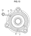
- Fig. 13 is a side view of the sensor for detecting a speed of rotation and the sensor holder.
- the sensor holder 20 is constituted only by the core metal member 21 (cover), and this core metal member 21 is secured to an inner end portion 1a of the outer ring 1 in the car width direction at the base end thereof, and is formed with a portion 21a with a substantially U-shaped section which is extended inwardly in the axial direction and inwardly in the radial direction from this base end. It is arranged such that the sensor main body 31 of the sensor 30 for detecting a speed of rotation is surround by this portion 21a with a substantially U-shaped section from an inner side in the car width direction.
- a space between the inner diameter side of the core metal member 21 (cover) and the inner end portion 3a of the inner ring 3 in the car width direction is in a labyrinth structure, as in the foregoing embodiment (Fig. 4), and a reference numeral 34a denotes a connecter.
- the sensor 30 is disposed to directly face the magnetic encoder 10.
- the magnetic encoder 10 is secured to the core metal 13 which is fixed to the inner ring 3, like in the first embodiment shown in Fig. 2.
- an outlet hole 50 for discharging water is provided in a lower portion of the core metal member 21 (cover), whereby water does not remain between the core metal member 21 (cover) and the bearing, so as to maintain the sealing performance satisfactorily.
- Fig. 14 includes a sectional view of an essential part of a hub unit for a driving wheel and a side view of a sensor for detecting a speed of rotation according to a first conventional example on a seventh embodiment of the present invention.
- Fig. 15A is a sectional view of an essential part of a hub unit for a driving wheel according to a second conventional example on the seventh embodiment of the present invention
- Fig. 15B is a side view of the sensor for detecting a speed of rotation.
- Fig. 16A is a sectional view of an essential part of a hub unit for a driving wheel according to the seventh embodiment of the present invention
- Fig. 16B is a side view of the sensor for detecting a speed of rotation.
- the sensor main body 31 of the sensor 30 for detecting a speed of rotation is provided with an IC 60.
- An IC terminal 61 is extended from this IC60 and is connected to the harness 34 inside the sub-body 31a.
- the IC terminal 61 is extended linearly (in a straight line form), an ordinary IC which is distributed in a market can be utilized as it is, which is excellent in cost performance.
- the fact that the IC terminal61 is extended linearly (in a straight line form) causes a problem that the length of the whole sensor 30 for detecting a speed of rotation in the radial direction is increased.
- the IC terminal 61 is turned around in a circle inside the sensor main body 31 in a ring shape, whereby it is arranged to reduce the radial length of the whole sensor 30 for detecting a speed of rotation, which, however, may increase the manufacturing cost in the second conventional example shown in Fig. 16.
- the IC terminal 61 is bent, for example, at about 90 degrees, which can resultantly reduce the radial length of the whole sensor 30 for detecting a speed of rotation and make it compact. At the same time, it is possible to reduce the manufacturing cost.
- Fig. 17A is a perspective view of a sensor for detecting a speed of rotation and a sensor holder of a hub unit for a driving wheel according to an eighth embodiment of the present invention.
- a sensor for detecting a speed of rotation is latched by or thread-engaged with a sensor holder to be fixed on a non-rotating side.
- the sensor for detecting a speed of rotation and the sensor holder may have complicated configurations, and further a fixing performance between the sensor for detecting a speed of rotation and the sensor holder may not be always sufficient since only the elasticity of the sensor holder is used as the retaining force.
- the sensor 30 for detecting a speed of rotation is formed with a convex portion 71 having a substantially arc-like form, while the sensor holder 20 is formed with a concave portion 72 having a substantially arc-like form. There is formed a peaked recessive part 72a for performing ratchet-fixing adjacent to this concave portion 72.
- the convex portion 71 of the sensor 30 for detecting a speed of rotation is fitted in the concave portion 72 of the sensor holder 20 and the sensor 30 for detecting a speed of rotation and the sensor holder 20 are rotated relatively to each other, the convex portion 71 is fitted in the peaked recessive part 72a like a ratchet, whereby the convex portion 71 having a substantially arc-like form and the peaked recessive part 72a can be brought into ratchet fitting with each other to be fixed.
- the sensor holder 21 can have a simplified shape. Further, since the elasticity is not used as a principal retaining force, there is no deterioration in the retaining performance, so that the fixing performance between the sensor 30 for detecting a speed of rotation and the sensor holder 20 can be enhanced.
- Fig. 17B is a perspective view of a variation of a sensor for detecting a speed of rotation of the hub unit for a driving wheel according to the eighth embodiment of the present invention.
- the sensor 30 for detecting a speed of rotation is formed with two convex portions 71 each having a substantially arc-like form. With this arrangement, the fixing performance between the sensor 30 for detecting a speed of rotation and the sensor holder 20 can be further enhanced.
- Fig. 17C is a perspective view of a variation of a sensor holder of the hub unit for a driving wheel according to the eighth embodiment of the present invention.
- the sensor holder 20 is formed with a hole 73 for inserting the sensing portion 35 of the sensor 30 for detecting a speed of rotation therethrough. Note that, it may be arranged to detect a speed of rotation through a non-magnetic material, without providing such a hole 73.
- Fig. 18 is a perspective view of a sensor for detecting a speed of rotation and a sensor holder of the hub unit for a driving wheel according to a variation of the eighth embodiment of the present invention.
- the sensor 30 for detecting a speed of rotation is provided with a flange 30a on the outer periphery thereof, and this flange 30a is fitted in the inner side of the cylindrical sensor holder 20.
- the flange 30a is formed with the convex portions 71 each having a substantially arc-like shape, while the sensor holder 20 is formed with concave portions 72 each having a substantially arc-like shape. Adjacently to the concave portion 72, there is formed the peaked recessive part 72a for performing ratchet fixing.
- the sensor holder 20 can have a simplified shape. Further, since the elasticity is not used as a principal retaining force, there is no deterioration in the retaining performance, so that the fixing performance between the sensor 30 for detecting a speed of rotation and the sensor holder 20 can be enhanced.
- the sensor 30 for detecting a speed of rotation or the sensor holder 20 except the ratchet fitting portion may take a fan-like shape, as shown in Figs. 17A to 17C, may take a cylindrical shape, as shown in Fig. 18, and may take another shape.
Landscapes
- Engineering & Computer Science (AREA)
- General Engineering & Computer Science (AREA)
- Mechanical Engineering (AREA)
- Physics & Mathematics (AREA)
- General Physics & Mathematics (AREA)
- Transmission And Conversion Of Sensor Element Output (AREA)
- Rolling Contact Bearings (AREA)
- Sealing Of Bearings (AREA)
Applications Claiming Priority (3)
| Application Number | Priority Date | Filing Date | Title |
|---|---|---|---|
| JP2003354022 | 2003-10-14 | ||
| JP2004110578A JP2005140320A (ja) | 2003-10-14 | 2004-04-02 | 駆動輪用ハブユニット |
| PCT/JP2004/014904 WO2005036183A1 (ja) | 2003-10-14 | 2004-10-01 | 駆動輪用ハブユニット |
Publications (2)
| Publication Number | Publication Date |
|---|---|
| EP1679518A1 true EP1679518A1 (de) | 2006-07-12 |
| EP1679518A4 EP1679518A4 (de) | 2008-12-31 |
Family
ID=34436934
Family Applications (1)
| Application Number | Title | Priority Date | Filing Date |
|---|---|---|---|
| EP04773701A Withdrawn EP1679518A4 (de) | 2003-10-14 | 2004-10-01 | Nabeneinheit für ein antriebsrad |
Country Status (4)
| Country | Link |
|---|---|
| US (1) | US7959358B2 (de) |
| EP (1) | EP1679518A4 (de) |
| JP (1) | JP2005140320A (de) |
| WO (1) | WO2005036183A1 (de) |
Cited By (4)
| Publication number | Priority date | Publication date | Assignee | Title |
|---|---|---|---|---|
| EP2048387A1 (de) * | 2007-10-10 | 2009-04-15 | JTEKT Corporation | Wälzlagervorrichtung mit Sensor |
| EP2093077A1 (de) * | 2008-02-25 | 2009-08-26 | JTEKT Corporation | Tragevorrichtung für Achsen |
| US8043010B2 (en) | 2007-01-25 | 2011-10-25 | Ntn Corporation | Wheel bearing apparatus incorporated with a wheel speed detecting apparatus |
| WO2016124193A1 (de) * | 2015-02-06 | 2016-08-11 | Schaeffler Technologies AG & Co. KG | Elektronikmodulanordnung zum einbau in einen zylindrischen bauraum sowie wälzlageranordnung |
Families Citing this family (29)
| Publication number | Priority date | Publication date | Assignee | Title |
|---|---|---|---|---|
| JP4609928B2 (ja) * | 2004-11-22 | 2011-01-12 | Ntn株式会社 | 回転速度検出装置付き車輪用軸受装置 |
| JP4692879B2 (ja) * | 2005-07-22 | 2011-06-01 | 株式会社ジェイテクト | ハブユニット |
| JP2008151623A (ja) * | 2006-12-18 | 2008-07-03 | Ntn Corp | センサホルダおよびこれを内蔵した回転速度検出装置付き車輪用軸受装置 |
| WO2008090741A1 (ja) * | 2007-01-23 | 2008-07-31 | Ntn Corporation | 回転速度検出装置付き車輪用軸受装置 |
| JP2008240760A (ja) * | 2007-03-26 | 2008-10-09 | Ntn Corp | 回転センサ付き車輪軸受装置 |
| JP2008241557A (ja) * | 2007-03-28 | 2008-10-09 | Ntn Corp | 回転検出センサ |
| JP2009025063A (ja) * | 2007-07-18 | 2009-02-05 | Ntn Corp | 回転検出センサ |
| JP2008275490A (ja) * | 2007-05-01 | 2008-11-13 | Ntn Corp | 回転検出センサ |
| WO2008136169A1 (ja) * | 2007-04-13 | 2008-11-13 | Ntn Corporation | 回転速度検出装置付き車輪用軸受装置 |
| DE112008001279T5 (de) | 2007-05-16 | 2010-04-15 | Ntn Corporation | Radlagervorrichtung mit eingebauter Raddrehzahl-Detektionsvorrichtung |
| JP2008286267A (ja) * | 2007-05-16 | 2008-11-27 | Ntn Corp | 回転速度検出装置付き車輪用軸受装置 |
| JP5063209B2 (ja) * | 2007-06-20 | 2012-10-31 | Ntn株式会社 | 回転検出センサ・固定部材取付体 |
| JP5167710B2 (ja) | 2007-07-17 | 2013-03-21 | 日本精工株式会社 | ハブユニット軸受 |
| JP2009052936A (ja) * | 2007-08-24 | 2009-03-12 | Ntn Corp | 回転検出センサ |
| JP5242102B2 (ja) * | 2007-09-06 | 2013-07-24 | Ntn株式会社 | 回転速度検出装置付き車輪用軸受装置 |
| JP5012392B2 (ja) * | 2007-10-10 | 2012-08-29 | 株式会社ジェイテクト | センサ付き転がり軸受装置 |
| JP2009138781A (ja) * | 2007-12-04 | 2009-06-25 | Ntn Corp | 回転速度検出装置付き車輪用軸受装置 |
| JP5194879B2 (ja) * | 2008-02-27 | 2013-05-08 | 日本精工株式会社 | 物理量測定装置付転がり軸受ユニット |
| US20120281939A1 (en) | 2009-10-06 | 2012-11-08 | Nsk Ltd. | Hub Unit Bearing |
| DE102010013214A1 (de) * | 2010-03-29 | 2011-09-29 | Schaeffler Technologies Gmbh & Co. Kg | Radlageranordnung mit Sensoranschlag |
| US9170309B2 (en) | 2010-06-08 | 2015-10-27 | Infineon Technologies Ag | Through bias pole for IGMR speed sensing |
| JP2012008073A (ja) * | 2010-06-28 | 2012-01-12 | Nsk Ltd | センサ付き転がり軸受 |
| WO2015010737A1 (en) * | 2013-07-24 | 2015-01-29 | Aktiebolaget Skf | A sensor-bearing unit, a mechanical system comprising at least one such unit and a mounting method |
| CA3046651A1 (en) | 2016-12-23 | 2018-06-28 | Gecko Robotics, Inc. | Inspection robot |
| US11307063B2 (en) | 2016-12-23 | 2022-04-19 | Gtc Law Group Pc & Affiliates | Inspection robot for horizontal tube inspection having vertically positionable sensor carriage |
| WO2020185719A2 (en) | 2019-03-08 | 2020-09-17 | Gecko Robotics, Inc. | Inspection robot |
| JP6774363B2 (ja) * | 2017-03-24 | 2020-10-21 | Ntn株式会社 | 車輪用軸受装置 |
| EP4326493A1 (de) | 2021-04-20 | 2024-02-28 | Gecko Robotics, Inc. | Flexibler inspektionsroboter |
| EP4327047A1 (de) | 2021-04-22 | 2024-02-28 | Gecko Robotics, Inc. | Systeme, verfahren und vorrichtung zur ultraschallprüfung einer oberfläche |
Citations (4)
| Publication number | Priority date | Publication date | Assignee | Title |
|---|---|---|---|---|
| EP0767385A1 (de) * | 1995-10-05 | 1997-04-09 | SKF INDUSTRIE S.p.A. | Lagereinheit mit schnell zu befestigendem Drehgeschwindigkeitsaufnehmer |
| EP0869365A1 (de) * | 1997-03-31 | 1998-10-07 | NSK Ltd. | Kugellager mit Drehzahlsensor |
| JP2003254985A (ja) * | 2002-03-04 | 2003-09-10 | Nsk Ltd | 回転速度検出装置付転がり軸受ユニット |
| EP1672373A1 (de) * | 2003-09-11 | 2006-06-21 | NSK Ltd. | Nabeneinheit für ein antriebsrad |
Family Cites Families (27)
| Publication number | Priority date | Publication date | Assignee | Title |
|---|---|---|---|---|
| JPS5892955A (ja) | 1981-11-30 | 1983-06-02 | Nissan Motor Co Ltd | 回転検出器のすき間調整機構 |
| JPH0250517U (de) * | 1988-10-05 | 1990-04-09 | ||
| JPH0420620Y2 (de) * | 1989-06-19 | 1992-05-12 | ||
| JPH0473616A (ja) | 1990-07-13 | 1992-03-09 | Victor Co Of Japan Ltd | 情報記録消去方法及びその装置 |
| JPH0754657Y2 (ja) * | 1990-11-06 | 1995-12-18 | 光洋精工株式会社 | 車軸用軸受装置 |
| JP2602146Y2 (ja) * | 1993-04-19 | 1999-12-27 | 日本精工株式会社 | 回転検出装置付転がり軸受 |
| FR2710985B1 (fr) | 1993-10-06 | 1995-11-24 | Skf France | Elément codeur pour roulement muni d'un ensemble capteur d'informations et roulement comportant un tel élément codeur. |
| US5470157A (en) * | 1994-03-29 | 1995-11-28 | The Timken Company | Bearing seal for sensing angular velocity |
| US5633437A (en) * | 1994-10-11 | 1997-05-27 | Sandoz Ltd. | Gene exhibiting resistance to acetolactate synthase inhibitor herbicides |
| JPH08122351A (ja) * | 1994-10-27 | 1996-05-17 | Ntn Corp | 回転センサを備える車輪支持軸受 |
| FR2740186B1 (fr) | 1995-10-20 | 1997-11-28 | Roulements Soc Nouvelle | Dispositif de fixation d'un capteur sur un palier a corps roulants |
| JPH09218215A (ja) | 1996-02-09 | 1997-08-19 | Sumitomo Electric Ind Ltd | 車両用センサシステム及び同システム用センサ |
| JP3480253B2 (ja) * | 1997-03-31 | 2003-12-15 | 日本精工株式会社 | 回転速度検出装置付転がり軸受ユニット |
| JP3497351B2 (ja) | 1997-03-31 | 2004-02-16 | 日本精工株式会社 | エンコーダ付転がり軸受ユニット |
| JP3573155B2 (ja) | 1997-03-31 | 2004-10-06 | 日本精工株式会社 | 回転速度検出装置付背面組み合わせ型転がり軸受ユニット |
| JP3480240B2 (ja) | 1997-05-14 | 2003-12-15 | 日本精工株式会社 | 回転速度検出装置付転がり軸受ユニット |
| JPH11326355A (ja) | 1998-05-11 | 1999-11-26 | Nippon Seiko Kk | 回転速度検出装置付転がり軸受ユニット |
| JP3811581B2 (ja) | 1999-02-02 | 2006-08-23 | 株式会社ジェイテクト | 回転速度検出装置 |
| JP3857453B2 (ja) | 1999-02-02 | 2006-12-13 | 株式会社ジェイテクト | 回転速度検出装置 |
| JP2000221202A (ja) | 1999-02-02 | 2000-08-11 | Koyo Seiko Co Ltd | 回転速度検出装置 |
| FR2794504B1 (fr) * | 1999-06-04 | 2001-07-13 | Roulements Soc Nouvelle | Roulement equipe d'un dispositif capteur d'informations |
| JP3755372B2 (ja) | 2000-02-29 | 2006-03-15 | 凸版印刷株式会社 | リチウム電池 |
| JP2001315501A (ja) | 2000-05-08 | 2001-11-13 | Ntn Corp | 車輪軸受装置 |
| JP4857485B2 (ja) * | 2001-04-25 | 2012-01-18 | 日本精工株式会社 | エンコーダ付車輪用回転支持装置 |
| JP2003075194A (ja) * | 2001-09-03 | 2003-03-12 | Koyo Seiko Co Ltd | パルサリングの着磁方法 |
| JP2003120703A (ja) * | 2001-10-16 | 2003-04-23 | Nsk Ltd | 回転検出装置付駆動輪用回転支持装置 |
| JP2003172347A (ja) * | 2001-12-06 | 2003-06-20 | Nsk Ltd | センサ付転動装置 |
-
2004
- 2004-04-02 JP JP2004110578A patent/JP2005140320A/ja active Pending
- 2004-10-01 WO PCT/JP2004/014904 patent/WO2005036183A1/ja active Application Filing
- 2004-10-01 EP EP04773701A patent/EP1679518A4/de not_active Withdrawn
- 2004-10-01 US US10/576,089 patent/US7959358B2/en not_active Expired - Fee Related
Patent Citations (4)
| Publication number | Priority date | Publication date | Assignee | Title |
|---|---|---|---|---|
| EP0767385A1 (de) * | 1995-10-05 | 1997-04-09 | SKF INDUSTRIE S.p.A. | Lagereinheit mit schnell zu befestigendem Drehgeschwindigkeitsaufnehmer |
| EP0869365A1 (de) * | 1997-03-31 | 1998-10-07 | NSK Ltd. | Kugellager mit Drehzahlsensor |
| JP2003254985A (ja) * | 2002-03-04 | 2003-09-10 | Nsk Ltd | 回転速度検出装置付転がり軸受ユニット |
| EP1672373A1 (de) * | 2003-09-11 | 2006-06-21 | NSK Ltd. | Nabeneinheit für ein antriebsrad |
Non-Patent Citations (1)
| Title |
|---|
| See also references of WO2005036183A1 * |
Cited By (6)
| Publication number | Priority date | Publication date | Assignee | Title |
|---|---|---|---|---|
| US8043010B2 (en) | 2007-01-25 | 2011-10-25 | Ntn Corporation | Wheel bearing apparatus incorporated with a wheel speed detecting apparatus |
| EP2048387A1 (de) * | 2007-10-10 | 2009-04-15 | JTEKT Corporation | Wälzlagervorrichtung mit Sensor |
| US8136994B2 (en) | 2007-10-10 | 2012-03-20 | Jtekt Corporation | Sensor-equipped rolling bearing apparatus |
| EP2093077A1 (de) * | 2008-02-25 | 2009-08-26 | JTEKT Corporation | Tragevorrichtung für Achsen |
| US8167500B2 (en) | 2008-02-25 | 2012-05-01 | Jtekt Corporation | Bearing apparatus for axle |
| WO2016124193A1 (de) * | 2015-02-06 | 2016-08-11 | Schaeffler Technologies AG & Co. KG | Elektronikmodulanordnung zum einbau in einen zylindrischen bauraum sowie wälzlageranordnung |
Also Published As
| Publication number | Publication date |
|---|---|
| WO2005036183A1 (ja) | 2005-04-21 |
| US20070278851A1 (en) | 2007-12-06 |
| US7959358B2 (en) | 2011-06-14 |
| EP1679518A4 (de) | 2008-12-31 |
| JP2005140320A (ja) | 2005-06-02 |
Similar Documents
| Publication | Publication Date | Title |
|---|---|---|
| US7959358B2 (en) | Hub unit for driving wheel | |
| JP2005140320A5 (de) | ||
| JP5334287B2 (ja) | ベアリングシール | |
| JPH0555070U (ja) | 車輪用軸受の回転速度検出装置 | |
| EP1433621B1 (de) | Wälzlagervorrichtung mit Sensor | |
| EP1672373B1 (de) | Nabeneinheit für ein antriebsrad | |
| WO2005040648A1 (ja) | センサ付きシール装置およびそれを用いた転がり軸受装置 | |
| JP5251922B2 (ja) | 駆動輪用ハブユニット | |
| JP3497351B2 (ja) | エンコーダ付転がり軸受ユニット | |
| US20030201766A1 (en) | Vehicle wheel bearing, wheel-speed sensor mechanism assembly, and wheel speed sensor | |
| EP2169407A1 (de) | Sensorvorrichtung und rollenlagervorrichtung mit dem sensor | |
| EP1591684A1 (de) | Sensoranordnungskörper, dichtungsvorrichtung und wälzlagervorrichtung für kraftfahrzeug | |
| JP4193504B2 (ja) | 転がり軸受装置の取付構造 | |
| JP2005140188A (ja) | センサ付きシール装置およびそれを用いた転がり軸受装置 | |
| JP2001301590A (ja) | 駆動車輪用軸受装置 | |
| JP2005098387A (ja) | センサ付きシール装置およびそれを用いた転がり軸受装置 | |
| JP3427829B2 (ja) | エンコーダ付転がり軸受ユニット | |
| JP2003307229A (ja) | パルス生成環内蔵軸受およびハブユニット軸受 | |
| JP4656917B2 (ja) | 回転速度検出装置付車輪用軸受装置 | |
| JP2001080307A (ja) | 車輪軸受装置 | |
| JP2005140187A (ja) | センサ付きシール装置およびそれを用いた転がり軸受装置 | |
| EP1610013A1 (de) | Sensoranordnungskörper, dichtungsvorrichtung und wälzlagervorrichtung für kraftfahrzeug | |
| JPH1138027A (ja) | 回転速度検出装置付転がり軸受ユニット | |
| JP2008267583A (ja) | 回転速度検出装置付き車輪用軸受装置 | |
| JP2005140146A (ja) | 駆動輪用ハブユニット |
Legal Events
| Date | Code | Title | Description |
|---|---|---|---|
| PUAI | Public reference made under article 153(3) epc to a published international application that has entered the european phase |
Free format text: ORIGINAL CODE: 0009012 |
|
| 17P | Request for examination filed |
Effective date: 20060512 |
|
| AK | Designated contracting states |
Kind code of ref document: A1 Designated state(s): DE FR GB |
|
| DAX | Request for extension of the european patent (deleted) | ||
| RBV | Designated contracting states (corrected) |
Designated state(s): DE FR GB |
|
| A4 | Supplementary search report drawn up and despatched |
Effective date: 20081127 |
|
| 17Q | First examination report despatched |
Effective date: 20090330 |
|
| STAA | Information on the status of an ep patent application or granted ep patent |
Free format text: STATUS: THE APPLICATION IS DEEMED TO BE WITHDRAWN |
|
| 18D | Application deemed to be withdrawn |
Effective date: 20090811 |