EP1661394B1 - Bilderfassungsvorrichtung, bilderfassungsverfahren und aufzeichnungsmedium, das ein fotografierverfahren aufzeichnet - Google Patents
Bilderfassungsvorrichtung, bilderfassungsverfahren und aufzeichnungsmedium, das ein fotografierverfahren aufzeichnet Download PDFInfo
- Publication number
- EP1661394B1 EP1661394B1 EP04771409A EP04771409A EP1661394B1 EP 1661394 B1 EP1661394 B1 EP 1661394B1 EP 04771409 A EP04771409 A EP 04771409A EP 04771409 A EP04771409 A EP 04771409A EP 1661394 B1 EP1661394 B1 EP 1661394B1
- Authority
- EP
- European Patent Office
- Prior art keywords
- photographing
- focus
- unit
- fixed
- stroke
- Prior art date
- Legal status (The legal status is an assumption and is not a legal conclusion. Google has not performed a legal analysis and makes no representation as to the accuracy of the status listed.)
- Expired - Lifetime
Links
- 238000000034 method Methods 0.000 title claims description 150
- 238000001514 detection method Methods 0.000 claims description 10
- 238000004590 computer program Methods 0.000 claims 1
- 230000008569 process Effects 0.000 description 135
- 230000001413 cellular effect Effects 0.000 description 29
- 230000003287 optical effect Effects 0.000 description 24
- 238000012545 processing Methods 0.000 description 23
- 230000006870 function Effects 0.000 description 21
- 230000003247 decreasing effect Effects 0.000 description 8
- 230000005540 biological transmission Effects 0.000 description 7
- 230000033001 locomotion Effects 0.000 description 7
- 230000000694 effects Effects 0.000 description 6
- 230000008859 change Effects 0.000 description 5
- 230000005236 sound signal Effects 0.000 description 5
- 238000012937 correction Methods 0.000 description 3
- 239000004973 liquid crystal related substance Substances 0.000 description 3
- 230000004044 response Effects 0.000 description 3
- 238000012546 transfer Methods 0.000 description 3
- 230000004913 activation Effects 0.000 description 2
- 238000010586 diagram Methods 0.000 description 2
- 230000007246 mechanism Effects 0.000 description 2
- 229910052751 metal Inorganic materials 0.000 description 2
- 239000002184 metal Substances 0.000 description 2
- 230000010355 oscillation Effects 0.000 description 2
- 230000004043 responsiveness Effects 0.000 description 2
- 230000003044 adaptive effect Effects 0.000 description 1
- 239000003990 capacitor Substances 0.000 description 1
- 238000004891 communication Methods 0.000 description 1
- 239000002131 composite material Substances 0.000 description 1
- 238000007906 compression Methods 0.000 description 1
- 238000013144 data compression Methods 0.000 description 1
- 230000001419 dependent effect Effects 0.000 description 1
- 239000000284 extract Substances 0.000 description 1
- 238000000605 extraction Methods 0.000 description 1
- 210000004932 little finger Anatomy 0.000 description 1
- 238000005259 measurement Methods 0.000 description 1
- 229910052709 silver Inorganic materials 0.000 description 1
- 239000004332 silver Substances 0.000 description 1
- -1 silver halide Chemical class 0.000 description 1
- 230000001960 triggered effect Effects 0.000 description 1
Images


Classifications
-
- H—ELECTRICITY
- H04—ELECTRIC COMMUNICATION TECHNIQUE
- H04N—PICTORIAL COMMUNICATION, e.g. TELEVISION
- H04N23/00—Cameras or camera modules comprising electronic image sensors; Control thereof
- H04N23/60—Control of cameras or camera modules
- H04N23/67—Focus control based on electronic image sensor signals
- H04N23/675—Focus control based on electronic image sensor signals comprising setting of focusing regions
-
- H—ELECTRICITY
- H04—ELECTRIC COMMUNICATION TECHNIQUE
- H04N—PICTORIAL COMMUNICATION, e.g. TELEVISION
- H04N23/00—Cameras or camera modules comprising electronic image sensors; Control thereof
- H04N23/60—Control of cameras or camera modules
- H04N23/695—Control of camera direction for changing a field of view, e.g. pan, tilt or based on tracking of objects
-
- H—ELECTRICITY
- H04—ELECTRIC COMMUNICATION TECHNIQUE
- H04N—PICTORIAL COMMUNICATION, e.g. TELEVISION
- H04N23/00—Cameras or camera modules comprising electronic image sensors; Control thereof
- H04N23/70—Circuitry for compensating brightness variation in the scene
- H04N23/72—Combination of two or more compensation controls
-
- H—ELECTRICITY
- H04—ELECTRIC COMMUNICATION TECHNIQUE
- H04N—PICTORIAL COMMUNICATION, e.g. TELEVISION
- H04N5/00—Details of television systems
- H04N5/76—Television signal recording
- H04N5/765—Interface circuits between an apparatus for recording and another apparatus
- H04N5/77—Interface circuits between an apparatus for recording and another apparatus between a recording apparatus and a television camera
- H04N5/772—Interface circuits between an apparatus for recording and another apparatus between a recording apparatus and a television camera the recording apparatus and the television camera being placed in the same enclosure
-
- H—ELECTRICITY
- H04—ELECTRIC COMMUNICATION TECHNIQUE
- H04N—PICTORIAL COMMUNICATION, e.g. TELEVISION
- H04N5/00—Details of television systems
- H04N5/76—Television signal recording
- H04N5/907—Television signal recording using static stores, e.g. storage tubes or semiconductor memories
-
- H—ELECTRICITY
- H04—ELECTRIC COMMUNICATION TECHNIQUE
- H04N—PICTORIAL COMMUNICATION, e.g. TELEVISION
- H04N9/00—Details of colour television systems
- H04N9/79—Processing of colour television signals in connection with recording
- H04N9/80—Transformation of the television signal for recording, e.g. modulation, frequency changing; Inverse transformation for playback
- H04N9/804—Transformation of the television signal for recording, e.g. modulation, frequency changing; Inverse transformation for playback involving pulse code modulation of the colour picture signal components
- H04N9/8042—Transformation of the television signal for recording, e.g. modulation, frequency changing; Inverse transformation for playback involving pulse code modulation of the colour picture signal components involving data reduction
- H04N9/8047—Transformation of the television signal for recording, e.g. modulation, frequency changing; Inverse transformation for playback involving pulse code modulation of the colour picture signal components involving data reduction using transform coding
-
- H—ELECTRICITY
- H04—ELECTRIC COMMUNICATION TECHNIQUE
- H04N—PICTORIAL COMMUNICATION, e.g. TELEVISION
- H04N23/00—Cameras or camera modules comprising electronic image sensors; Control thereof
- H04N23/60—Control of cameras or camera modules
- H04N23/63—Control of cameras or camera modules by using electronic viewfinders
- H04N23/633—Control of cameras or camera modules by using electronic viewfinders for displaying additional information relating to control or operation of the camera
-
- H—ELECTRICITY
- H04—ELECTRIC COMMUNICATION TECHNIQUE
- H04N—PICTORIAL COMMUNICATION, e.g. TELEVISION
- H04N5/00—Details of television systems
- H04N5/76—Television signal recording
- H04N5/765—Interface circuits between an apparatus for recording and another apparatus
Definitions
- the present invention relates to an image sensing apparatus and image sensing method suitable for a digital still camera, a cellular phone with a camera function, and the like, and a recording medium which records a photographing method.
- a camera with an autofocus (AF) function executes photographing at a fixed focus having a predetermined depth of field without using the AF function in order to take a snapshot or to quickly perform photographing without any failure in a situation in which it is difficult to focus the lens by the AF function; see, e.g.,
- the autofocus mode and fixed-focus mode must be arbitrarily selected by mode switching. Quick photographing is impossible in the fixed-focus mode immediately after switching from a state in which the autofocus mode is selected. The user may miss a good photo opportunity.
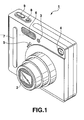
- FIG. 1 shows the outer appearance of the digital still camera, and mainly shows the arrangements of the front and top surfaces.
- a digital still camera 1 comprises, on the front surface of an almost rectangular thin-plate like metal outer body, a photographing lens 2, self-timer lamp 3, optical viewfinder window 4, microphone 5, flash emission unit 6-, and gripper bar 7.
- a power key 8 and shutter key 9 are arranged on the right end (viewed from the user) of the top surface.
- the photographing lens 2 has an AF function and a zoom function of changing the focal length in a stepless manner.
- the photographing lens 2 collapses into the body in power-off or playback serving as a basic mode.
- the gripper bar 7 is a band-like metal projection which is buried so that the user can reliably grip the housing with the middle, third, and little fingers of his right hand when he grips the digital still camera 1 with his right hand from the right side surface of the housing in photographing.
- the power key 8 is a key operated to turn on/off the power supply.
- the shutter key 9 designates the photographing timing in the photographing mode.
- the rear surface of the digital still camera 1 is equipped with a mode switch, speaker, menu key, cross key (exposure setting unit), set key, optical viewfinder, flash charge lamp, display, and the like.
- the bottom surface of the digital still camera 1 is equipped with a memory card slot for allowing the operator to insert/remove a memory card used as a recording medium, and a USB (Universal Serial Bus) connector as a serial interface connector for connecting an external personal computer or the like.
- a memory card slot for allowing the operator to insert/remove a memory card used as a recording medium
- a USB (Universal Serial Bus) connector as a serial interface connector for connecting an external personal computer or the like.
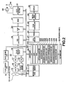
- the electronic circuit configuration of the digital still camera 1 will be explained with reference to FIG. 2 .
- a timing generator (TG) 14 and vertical driver 15 scan and drive a CCD 13 serving as an image sensing element arranged on the back side of the photographing optical axis of a lens optical system 12 which changes the in-focus position or stop position by driving of a motor (M) 11 and forms the photographing lens 2.
- the CCD 13 outputs a photoelectrically converted output of one frame that corresponds to an optical image formed every predetermined cycle.
- the motor (M) 11, lens optical system 12, and CCD 13 form a photographing unit.
- the photoelectrically converted output properly undergoes gain adjustment for each of primary color components R, G, and B in the state of a signal of an analog value.
- the resultant signal is sampled and held by a sample-and-hold circuit (S/H) 16, and converted into digital data by an A/D converter 17.
- the digital data undergoes a color process including a pixel interpolation process and y correction process by a color process circuit 18 to generate a luminance signal Y and color difference signals Cb and Cr of digital values.
- DMA Direct Memory Access
- the DMA controller 19 temporarily writes the luminance signal Y and color difference signals Cb and Cr output from the color process circuit 18 in the internal buffer of the DMA controller 19 by using a composite sync signal, memory write enable signal, and clock signal from the color process circuit 18.
- the luminance signal Y and color difference signals Cb and Cr are then DMA-transferred to a DRAM 21 used as a buffer memory via-a DRAM interface (I/F) 20.
- a controller 22 is comprised of a CPU 221, a ROM 222 which permanently stores an operating program that includes a process to the operation of the shutter key 9 in the photographing mode (to be described later) and is executed by the CPU 221, a RAM 223 used as a work memory, an autoexposure unit 224 which automatically sets a correct exposure value in the photographing mode, a detection unit 225 which detects the designated operation state of the shutter key 9, an exposure comparison unit 226 which compares the correct exposure value with a preset exposure value, an exposure detection unit 229 which detects that an arbitrary exposure value is set, a focal length comparison unit 228 which compares the current focal length in the photographing mode with a preset focal length, a focus control unit 227 which prompts the user to select whether to operate the autofocus function or set a fixed-focus position in the photographing mode, a focus range determination unit 230 which determines a fixed-focus range containing an object to be photographed from a plurality of fixed-focus ranges in the photographing mode, and a notification
- the controller 22 reads out the luminance and color difference signals from the DRAM 21 via the DRAM interface 20, and writes these signals in a VRAM 24 via a VRAM controller 23.
- a digital video encoder 25 periodically reads out the luminance and color difference signals from the VRAM 24 via the VRAM controller 23, generates a video signal on the basis of these data, and outputs the video signal to a display 26.
- the display 26 is arranged on the rear surface of the digital still camera 1, as described above.
- the display 26 functions as a monitor display (electronic viewfinder) in the photographing mode.
- the display 26 performs display based on the video signal from the digital video encoder 25, and displays in real time an image based on image information received from the VRAM controller 23 at this time.
- the shutter key 9 is operated at a timing when a still image is to be taken, and then a trigger signal is generated.
- the controller 22 stops DMA transfer of the luminance and color difference signals of one frame from the CCD 13 to the DRAM 21 in response to the trigger signal.
- the controller 22 drives the CCD 13 at an F-number and shutter speed complying with correct exposure conditions, obtains luminance and color difference signals of one frame, and transfers them to the DRAM 21. After that, the controller 22 disconnects this route, and transits to a recording/save state.
- the controller 22 reads out the luminance and color difference signals of one frame written in the DRAM 21 via the DRAM interface 20 for a unit called a basic block of vertical 8 pixels X horizontal 8 pixels for each of the Y, Cb, and Cr components.
- the controller 22 writes the signals in a JPEG (Joint Photograph coding Experts Group) circuit 27.
- the JPEG circuit 27 compresses data by processes such as ADCT (Adaptive Discrete Cosine Transform) and entropy coding (e.g., Huffman coding).
- the controller 22 reads outs the encoded data as a data file of one image from the JPEG circuit 27, and writes the data file in a memory card 28 detachably mountable as a recording medium of the digital still camera 1 or an internal memory 29 which is permanently incorporated in the digital still camera 1.
- the controller 22 activates the route extending from the CCD 13 to the DRAM 21 again upon the end of the compression process for luminance and color difference signals of one frame and write of compressed data in the memory card 28 or internal memory 29.
- the controller 22 is connected to a key input unit 30, audio processing unit 31, and flash driving unit 32.
- the key input unit 30 is made up of the power key 8, shutter key 9, mode switch, menu key, cross key, set key, and the like. Signals accompanying these key operations are directly sent to the controller 22.
- the audio processing unit 31 comprises a sound source circuit such as a PCM sound source.
- the audio processing unit 31 digitizes an audio signal input from the microphone (MIC) 5, and compresses data in accordance with a predetermined data file format, e.g., MP3 (MPEG-1 audio layer 3) standard.
- the audio processing unit 31 creates an audio data file and sends it to the memory card 28 or internal memory 29.
- the audio processing unit 31 decompresses an audio data file sent from the memory card 28 or internal memory 29, and converts the data into an analog signal.
- the audio processing unit 31 drives a speaker (SP) 33 arranged on the rear surface of the digital still camera 1, and outputs the sound from the speaker (SP) 33.
- SP speaker
- the flash driving unit 32 charges a large-capacity flash capacitor (not shown), and drives the flash emission unit 6 under the control of the controller 22 to emit flash light.
- still image data files prepared by compressing still image data by the JPEG circuit 27 are temporarily successively recorded on the memory card 28 or internal memory 29 while the shutter key 9 is kept operated.
- a series of still image data files are set again as a motion JPEG data file (AVI file) at once.
- the controller 22 selectively reads out image data recorded on the memory card 28 or internal memory 29.
- the JPEG circuit 27 decompresses the compressed image data in procedures opposite to data compression procedures in the photographing mode.
- the decompressed image data are held in the DRAM 21 via the DRAM interface 20, and the contents held by the DRAM 21 are stored in the VRAM 24 via the VRAM controller 23.
- the image data are periodically read out from the VRAM 24 to generate video signals, and the video signals are played back on the display 26.
- the following processes are basically executed by the controller 22 on the basis of a permanently stored program.
- the shutter key 9 operates by two stroke operations.
- AF operation is executed to lock an in-focus state and exposure state by the first stroke generally called a "half stroke”.
- Photographing in the locked in-focus state and exposure state is executed by the second stroke generally called a "full stroke”.
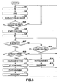
- FIG. 3 shows process contents in the photographing mode.
- An AE process is first executed at a focal length corresponding to the currently selected zoom position of the photographing lens 2.
- a correct exposure value is obtained to set an F-number and shutter speed (step A01).
- the shutter speed is adjusted to a value corresponding to the frame rate of the monitor state, e.g., to a speed much higher than 1/30 [sec] for a frame rate of 30 frames/[sec].
- An image is obtained from the CCD 13, and adjusted by the color process circuit 18 so that the white balance corresponds to the color temperature of the light source by an auto white balance (AWB) process (step A02). While a through image is displayed on the display 26 (step A03), whether the shutter key 9 of the key input unit 30 is pressed halfway is determined (step A04). This process is repetitively executed until the shutter key 9 is pressed halfway.
- AVB auto white balance
- step A04 Counting operation of an internal counter t which counts an elapsed time in the half stroke state starts (step A05).
- An AF process is so performed as to focus the lens to a predetermined focus area, and the in-focus position is locked (step A06).
- the F-number and shutter speed which have been acquired in the AE process of immediately preceding step A01 and provide correct exposure are locked.
- step A07 Whether the shutter key 9 is pressed fully in the state in which the photographing conditions are locked (step A07), and whether the shutter key 9 is kept pressed halfway (step A08) are repetitively determined. While the shutter key 9 is confirmed to be kept pressed halfway, the flow waits until the shutter key 9 is pressed fully.
- step A08 If the half stroke of the shutter key 9 is canceled, this state is determined in step A08, the photographing conditions are unlocked, and the flow returns to the process from step A01 again.
- step A07 If the shutter key 9 is pressed fully in the state in which the photographing conditions are locked, this state is determined in step A07, and whether the count value of the internal counter t of the controller 22 is equal to or smaller than a predetermined value, e.g., a value corresponding to time 1 [sec] is determined (step A09).
- a predetermined value e.g., a value corresponding to time 1 [sec]
- the time represented by the predetermined value for the count value of the internal counter t can be arbitrarily set by the user in advance.
- the count value of the internal counter t is determined to be larger than the predetermined value, it is determined that a corresponding time has elapsed during a shift from the half stroke to full stroke of the shutter key 9 and no quick photographing is required.
- the camera shifts to the image data recording/save state based on basic operation.
- image data by photographing is obtained while the photographing conditions are kept locked (step A14).
- the image data obtained by photographing is recorded and saved as a file in the memory card 28 or internal memory 29 (step A15).
- a series of photographing processes end, and the flow returns to the process from step A01 again in order to prepare for the next photographing.
- step A09 If the count value of the internal counter t is determined in step A09 to be equal to or smaller than the predetermined value, the user is determined to want to quickly operate the shutter key 9 and immediately photograph an object.
- a predetermined in-focus position which corresponds to the current zoom position of the photographing lens 2 and provides the depth of field as large as possible is fixed and set (step A10).
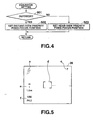
- FIG. 4 shows a subroutine representing detailed contents of the pan-focus process. Whether the digital still camera 1 is used outdoors at this time is determined from whether the color temperature of the light source obtained by the auto white balance process in immediately preceding step A02 is the color temperature of sunlight (step S01).
- the lens optical system 12 which forms the photographing lens 2 has two fixed-focus ranges: a near-view fixed-focus range in which the lens is always focused on an object within a range of, e.g., 0.4 [m] to 10 [m], and a distant-view fixed-focus range in which the lens is always focused on an object within a range of 1.5 [m] to infinity ( ⁇ ).
- step S01 If it is determined in step S01 that the color temperature of the light source obtained by the auto white balance process is that of sunlight and the camera 1 is used outdoors, the object is determined to be distant from the camera 1 to a certain degree.
- the position of the lens optical system 12 is set to the distant-view fixed-focus range (step S02), and the pan-focus setting subroutine ends.
- step S01 If it is determined in step S01 that the color temperature of the light source obtained by the auto white balance process is not that of sunlight and the camera 1 is not used outdoors, the object is determined to be close to the camera 1 to a certain degree.
- the position of the lens optical system 12 is set to the near-view fixed-focus range (step S03), and the pan-focus setting subroutine ends.
- a so-called stop-down AE process of setting the F-number as large as possible from the correct exposure value obtained in immediately preceding step A01 and decreasing the shutter speed in correspondence with the F-number is executed together with the pan-focus process in step A10 (step A11). Immediately after this process, the camera shifts to the image data recording/save state.
- image data by image sensing is obtained (step A12).
- the image data obtained by photographing is recorded and saved as a file in the memory card 28 or internal memory 29 (step A13).
- a series of photographing processes end, and the flow returns to the process from step A01 again in order to prepare for the next photographing.
- the autofocus and fixed focus can be arbitrarily switched and selected in accordance with the operation state of the shutter key 9 having two operation strokes.
- Quick photographing operation can be executed, as needed.
- photographing is so executed as to set the pan-focus.
- the pan-focus is intentionally set, and photographing can shift to a state in which a so-called out-of-focus state hardly occurs.
- a range corresponding to photographing conditions is determined as a pan-focus setting from a plurality of, e.g., two fixed-focus ranges. In switching to and selecting a fixed-focus position, the determined fixed-focus range is selected. Photographing can be executed while the lens is more accurately focused on an object.
- the fixed-focus range determination requirement whether an object image is to be taken indoors or outdoors is determined from the result of color temperature adjustment for the light source by using the auto white balance function.
- the fixed-focus range in which the object image is located can be more accurately determined without any burden on the user. Photographing can be executed while the lens is much more accurately focused.
- the fixed-focus range set in step S02 or S03 may be expressed by a numerical value and displayed on the display 26 of the camera 1.
- FIG. 5 shows an example in which the fixed-focus range is displayed as one of various photographing data on the display 26 for a predetermined time immediately after photographing.
- a flash emission mode a a remaining number c of photographable images, a focus frame d , a fixed-focus range e , and an exposure value (shutter speed and F-number) f are properly distributed and displayed on the display 26.
- the distant-view fixed-focus range is represented by a concrete numerical value "1.5 m to infinity ( ⁇ ), as shown in FIG. 5 .
- ⁇ 1.5 m to infinity
- the outer appearance is basically the same as that in FIG. 1
- the electronic circuit configuration is basically the same as that in FIG. 2 .
- the same numerals denote the same parts, and an illustration and description thereof will be omitted.
- the following processes are basically executed by a controller 22 on the basis of a permanently stored program.
- a shutter key 9 operates by two stroke operations.
- AF operation is executed to lock an in-focus state and exposure state by the first stroke generally called a "half stroke”.
- Photographing in the locked in-focus state and exposure state is executed by the second stroke generally called a "full stroke”.
- FIGS. 6 and 7 show power-on operation along with the operation of a power key 8 and process contents in the photographing mode as a basic mode automatically set after power-on.
- the flow waits until the power supply is turned on by the operation of the power key 8 (step B01) .
- step B01 If the power supply is turned on by the operation of the power key 8, the controller 22 determines this state in step B01, and starts counting operation of an internal counter t1 which counts an elapsed time after power-on (step B02).
- An AE process is executed at a focal length corresponding to the currently selected zoom position of a photographing lens 2.
- a correct exposure value is obtained to set an F-number and shutter speed (step B03).
- the shutter speed is adjusted to a value corresponding to the frame rate of the monitor state, e.g., to a speed much higher than 1/30 [sec] for a frame rate of 30 frames/[sec].
- An image is obtained from a CCD 13, and adjusted by a color process circuit 18 so that the white balance corresponds to the color temperature of the light source by an auto white balance (AWB) process (step B04). While a through image is displayed on a display 26 (step B05), whether the shutter key 9 of a key input unit 30 is pressed halfway is determined (step B06). This process is repetitively executed until the shutter key 9 is pressed halfway.
- AVB auto white balance
- step B05 If the shutter key 9 is pressed halfway, this state is determined in step B05. Whether the count value of the internal counter t1 of the controller 22 is equal to or a smaller than a predetermined value, e.g., a value corresponding to time 5 [sec] is determined (step B07).
- a predetermined value e.g., a value corresponding to time 5 [sec] is determined (step B07).
- the time represented by the predetermined value for the count value of the internal counter t1 can be arbitrarily set by the user in advance.
- a predetermined in-focus position which corresponds to the current zoom position of the photographing lens 2 and provides the depth of field as large as possible is fixed and set (step B08).
- step S01 whether a digital still camera 1 is used outdoors at this time is determined from whether the color temperature of the light source obtained by the auto white balance process in immediately preceding step B04 is the color temperature of sunlight (step S01).
- a lens optical system 12 which forms the photographing lens 2 has two fixed-focus ranges: a near-view fixed-focus range in which the lens is always focused on an object within a range of, e.g., 0.4 [m] to 10 [m], and a distant-view fixed-focus range in which the lens is always focused on an object within a range of 1.5 [m] to infinity ( ⁇ ).
- step S01 If it is determined in step S01 that the color temperature of the light source obtained by the auto white balance process is that of sunlight and the camera 1 is used outdoors, the object is determined to be distant from the camera 1 to a certain degree.
- the position of the lens optical system 12 is set to the distant-view fixed-focus range (step S02), and the pan-focus setting subroutine ends.
- step S01 If it is determined in step S01 that the color temperature of the light source obtained by the auto white balance process is not that of sunlight and the camera 1 is not used outdoors, the object is determined to be close to the camera 1 to a certain degree.
- the position of the lens optical system 12 is set to the near-view fixed-focus range (step S03), and the pan-focus setting subroutine ends.
- a so-called stop-down AE process of setting the F-number as large as possible from the correct exposure value obtained in immediately preceding step B03 and decreasing the shutter speed in correspondence with the F-number is executed together with the pan-focus process in step B08 (step B09).
- step B10 Whether the shutter key 9 is pressed fully (step B10), and whether the shutter key 9 is kept pressed halfway (step B11) are repetitively determined. While the shutter key 9 is confirmed to be kept pressed halfway, the flow waits until the shutter key 9 is pressed fully.
- step B11 If the half stroke of the shutter key 9 is canceled, this state is determined in step B11, the photographing conditions for obtaining the pan-focus state are unlocked, and the flow returns to the process from step B03 again.
- step B10 If the shutter key 9 is pressed fully in the state in which the photographing conditions are locked, this state is determined in step B10, and the camera immediately shifts to the image data recording/save state.
- step B12 image data by image sensing is obtained (step B12), and the image data obtained by photographing is recorded and saved as a file in a memory card 28 or internal memory 29 (step B13).
- step B13 image data by image sensing is obtained (step B12), and the image data obtained by photographing is recorded and saved as a file in a memory card 28 or internal memory 29 (step B13).
- a series of photographing processes end, and the flow returns to the process from step B03 again in order to prepare for the next photographing.
- step B07 If the count value of the internal counter t1 which counts an elapsed time after power-on is larger than the predetermined value in step B07, it is determined that a corresponding time has elapsed from the power-on timing by the operation of the power key 8 and no quick photographing is required.
- An AF process is performed to obtain an in-focus position so as to focus the lens to a predetermined focus area, and the in-focus position is obtained and locked (step B15).
- the F-number and shutter speed which have been acquired in the AE process of immediately preceding step B03 and provide correct exposure are determined and locked.
- step B16 Whether the shutter key 9 is pressed fully in the state in which the photographing conditions are locked (step B16), and whether the shutter key 9 is kept pressed halfway (step B17) are repetitively determined. While the shutter key 9 is confirmed to be kept pressed halfway, the flow waits until the shutter key 9 is pressed fully.
- step B17 If the half stroke of the shutter key 9 is canceled, this state is determined in step B17, the photographing conditions are unlocked, and the flow returns to the process from step B03 again.
- step B16 If the shutter key 9 is pressed fully in the state in which the photographing conditions are locked, this state is determined in step B16, and whether the count value of the internal counter t2 of the controller 22 is equal to or smaller than a predetermined value, e.g., a value corresponding to time 1 [sec] is determined (step B18).
- a predetermined value e.g., a value corresponding to time 1 [sec]
- the time represented by the predetermined value for the count value of the internal counter t2 can be arbitrarily set by the user in advance.
- the count value of the internal counter t2 is determined to be larger than the predetermined value, it is determined that a corresponding time has elapsed from the half stroke to full stroke of the shutter key 9 and no quick photographing is required.
- the camera shifts to the general image data recording/save state.
- step B23 image data by image sensing is obtained (step B23), and the image data obtained by photographing is recorded and saved as a file in the memory card 28 or internal memory 29 (step B24).
- step B24 image data by image sensing is obtained (step B23), and the image data obtained by photographing is recorded and saved as a file in the memory card 28 or internal memory 29 (step B24).
- a series of photographing processes end, and the flow returns to the process from step B03 again in order to prepare for the next photographing.
- step B18 If the count value of the internal counter t2 is equal to or smaller than the predetermined value in step B18, it is determined that no long time has elapsed from the half stroke to full stroke of the shutter key 9 and the user wants to quickly operate the shutter key 9 and immediately photograph an object.
- a predetermined in-focus position which corresponds to the current zoom position of the photographing lens 2 and provides the depth of- field-as large as possible is fixed and set (step B19).
- step S01 whether the digital still camera 1 is used outdoors at this time is determined from whether the color temperature of the light source obtained by the auto white balance process in immediately preceding step B04 is the color temperature of sunlight (step S01).
- step S01 If it is determined in step S01 that the color temperature of the light source obtained by the auto white balance process is that of sunlight and the camera 1 is used outdoors, the object is determined to be distant from the camera 1 to a certain degree.
- the position of the lens optical system 12 is set to the distant-view fixed-focus range (step S02), and the pan-focus setting subroutine ends.
- step S01 If it is determined in step S01 that the color temperature of the light source obtained by the auto white balance process is not that of sunlight and the camera 1 is not used outdoors, the object is determined to be close to the camera 1 to a certain degree.
- the position of the lens optical system 12 is set to the near-view fixed-focus range (step S03), and the pan-focus setting subroutine ends.
- a so-called stop-down AE process of setting the F-number as large as possible from the correct exposure value obtained in immediately preceding step B03 and decreasing the shutter speed in correspondence with the F-number is executed together with the pan-focus process in step B19 (step B20).
- the camera immediately shifts to the image data recording/save state.
- step B21 After image data by image sensing is obtained (step B21), the obtained image data is recorded and saved as a file in the memory card 28 or internal memory 29 (step B22). A series of photographing processes end, and the flow returns to the process from step B03 again in order to prepare for the next photographing.
- the second example executes photographing in which the pan-focus is set by the half stroke of the shutter key 9 within only a predetermined time immediately after power-on.
- This example is effective particularly for a case in which the power supply is turned on by the operation of the power key 8 from the power-off state of the digital still camera 1 and photographing is quickly executed at a fixed focus. This can further reduce the possibility of missing a photo opportunity.
- the outer appearance is basically the same as that in FIG. 1
- the electronic circuit configuration is basically the same as that in FIG. 2 .
- the same numerals denote the same parts, and an illustration and description thereof will be omitted.
- the following processes are basically executed by a controller 22 on the basis of a permanently stored program.
- a shutter key 9 operates by two stroke operations.
- AF operation is executed to lock an in-focus state and exposure state by the first stroke generally called a "half stroke”.
- Photographing in the locked in-focus state and exposure state is executed by the second stroke generally called a "full stroke”.
- FIG. 8 shows process contents in the photographing mode.
- An AE process is first executed at a focal length corresponding to the currently selected zoom position of a photographing lens 2.
- a correct exposure value is obtained to set an F-number and shutter speed (step C01).
- the shutter speed is adjusted to a value corresponding to the frame rate of the monitor state, e.g., to a speed much higher than 1/30 [sec] for --a frame rate of 30 frames/[sec].
- An image is -obtained from a CCD 13, and adjusted by a color process circuit 18 so that the white balance corresponds to the color temperature of the light source by an auto white balance (AWB) process (step C02). While a through image is displayed on a display 26 (step C03), whether the shutter key 9 of a key input unit 30 is pressed halfway is determined (step C04). This process is repetitively executed until the shutter key 9 is pressed halfway.
- AVB auto white balance
- step C04 If the shutter key 9 is pressed halfway, this state is determined in step C04.
- An AF process starts so as to focus the lens to a predetermined focus area (step C05).
- the F-number and shutter speed which have been acquired in the AE process of immediately preceding step C01 and provide correct exposure are locked.
- step C06 Whether the shutter key 9 is pressed fully immediately after the start of the AF process in step C05 (step C06), and whether the shutter key 9 is kept pressed halfway (step C07) are repetitively determined. While the shutter key 9 is confirmed to be kept pressed halfway, the flow waits until the shutter key 9 is pressed fully.
- step C07 If the half stroke of the shutter key 9 is canceled, this state is determined in step C07, the photographing conditions are unlocked, and the flow returns to the process from step C01 again.
- step C06 If the shutter key 9 is pressed fully, this state is determined in step C06, and whether the AF process which has started in step C05 has been completed and the in-focus position has been locked is determined (step C08).
- the camera shifts to the image data recording/save state based on basic operation.
- step C13 After image data by image sensing is obtained on the basis of the locked photographing conditions (step C13), the image data obtained by photographing is recorded and saved as a file in a memory card 28 or internal memory 29 (step C14). A series of photographing processes end, and the flow returns to the process from step C01 again in order to prepare for the next photographing.
- step C08 If it is determined in step C08 that the in-focus position has not been locked and the AF process has not been completed, the user is determined to want to quickly operate the shutter key 9 and immediately photograph an object.
- a predetermined in-focus position which corresponds to the current zoom position of the photographing lens 2 and provides the depth of field as large as possible is fixed and set (step C09).
- step S01 whether a digital still camera 1 is used outdoors at this time is determined from whether the color temperature of the light source obtained by the auto white balance process in immediately preceding step C02 is the color temperature of sunlight (step S01).
- a lens optical system 12 which forms the photographing lens 2 has two fixed-focus ranges: a near-view fixed-focus range in which the lens is always focused on an object within a range of, e.g., 0.4 [m] to 10 [m], and a distant-view fixed-focus range in which the lens is always focused on an object within a range of 1.5 [m] to infinity ( ⁇ ).
- step S01 If it is determined in step S01 that the color temperature of the light source obtained by the auto white balance process is that of sunlight and the camera 1 is used outdoors, the object is determined to be distant from the camera 1 to a certain degree.
- the position of the lens optical system 12 is set to the distant-view fixed-focus range (step S02), and the pan-focus setting subroutine ends.
- step S01 If it is determined in step S01 that the color temperature of the light source obtained by the auto white balance process is not that of sunlight and the camera 1 is not used outdoors, the object is determined to be close to the camera 1 to a certain degree.
- the position of the lens optical system 12 is set to the near-view fixed-focus range (step S03), and the pan-focus setting subroutine ends.
- a so-called stop-down AE process of setting the F-number as large as possible from the correct exposure value obtained in immediately preceding step C01 and decreasing the shutter speed in correspondence with the F-number is executed together with the pan-focus process in step C09 (step C10).
- the camera immediately shifts to the image data recording/save state.
- step C11 After image data by image sensing is obtained (step C11), the obtained image data is recorded and saved as a file in the memory card 28 or internal memory 29 (step C12). A series of photographing processes end, and the flow returns to the process from step C01 again in order to prepare for the next photographing.
- the camera may have only one focus range or three or more focus ranges in accordance with, e.g., the optical characteristic of the lens optical system 12 which forms the photographing lens 2, or camera use specifications required in designing the digital still camera 1.
- a plurality of fixed-focus ranges are set, and which of the fixed-focus ranges contains an object image is determined from the color temperature of the light source that is obtained by auto white balance adjustment.
- the present invention is not limited to this.
- the light source periodically flickers, it is a fluorescent light, and the camera is determined to be used indoors.
- indoor and outdoor locations are discriminated on the basis of the currently set flash emission mode, a selected scene program, or the like. In this manner, various methods of determining one of a plurality of set fixed-focus ranges are conceivable.
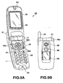
- FIGS. 9A and 9B show the outer appearance of a cellular phone 40 according to the third example.
- the cellular phone 40 has a foldable shape in which two housings 42 and 43 are integrally assembled pivotally within a predetermined angle range via a hinge 41.
- FIG. 9A shows the inner surface when the cellular phone 40 is opened at maximum.
- FIG. 9B mainly shows the outer surface of the upper housing 42 when the cellular phone 40 is folded.
- a speaker 44 serving as a receiver and a main display 45 are arranged on the inner surface of the upper housing 42.
- Various keys 46 including a dial key and the like, and a microphone 47 serving as a transceiver are arranged on the inner surface of the lower housing 43.
- a camera 48, photographing light 49, and sub-display 50 are arranged on the outer surface of the upper housing 42.
- An antenna 51 extending into the lower housing 43 externally projects from the hinge 41.
- the camera 48 has an AF function and a zoom function of changing the focal length in a stepless manner.
- the various keys 46 include a camera key 46a which sets a camera mode, and a set (SET) key 46b (designation unit) also functioning as a shutter key, in addition to a dial key, power key, and a key for channel connection/disconnection. Further, the various keys 46 include a shutter key 46c (designation unit) on a side end face of the hinge 41 that is not equipped with the antenna 51, and a ring key 46d (exposure setting unit) which designates, e.g., the zoom and exposure value of the camera 48 and is positioned using the set key 46b as a center.
- SET set
- ring key 46d exposure setting unit
- FIG. 10 shows the circuit configuration of the cellular phone 40.
- the antenna 51 communicates with the nearest base station by CDMA.
- the antenna 51 is connected to an RF unit 61.
- the RF unit 61 Upon reception, the RF unit 61 separates a signal input from the antenna 51 from the frequency axis by a duplexer.
- the RF unit 61 mixes the separated signal with a local oscillation signal of a predetermined frequency output from a PLL synthesizer to convert the frequency into an IF signal.
- the RF unit 61 extracts only a reception frequency channel by a broadband BPF, keeps the signal level of a desired reception wave constant by an AGC amplifier, and then outputs the resultant signal to a modulation/demodulation unit 62 on the output stroke.
- the RF unit 61 controls the transmission power of an OQPSK (Offset Quadri-Phase Shift Keying) modulated signal from the modulation/demodulation unit 62 by the AGC amplifier under the control of a controller 65 (to be described later).
- OQPSK Offset Quadri-Phase Shift Keying
- the RF unit 61 mixes the signal with a local oscillation signal of a predetermined frequency output from the PLL synthesizer to convert the frequency into the RF band.
- the RF unit 61 amplifiers the power to a large one by a PA (Power Amplifier), and radiates and transmits the resultant signal from the antenna 51 via the duplexer.
- PA Power Amplifier
- the modulation/demodulation unit 62 Upon reception, the modulation/demodulation unit 62 separates an IF signal from the RF unit 61 into a baseband I ⁇ Q (In-phase ⁇ Quadrature-phase) signal by a quadrature detector. The modulation/demodulation unit 62 digitizes the signal, and outputs it to a CDMA unit 63.
- I ⁇ Q In-phase ⁇ Quadrature-phase
- the modulation/demodulation unit 62 converts an I ⁇ Q signal of a digital value sent from the CDMA unit 63 into an analog signal.
- the modulation/demodulation unit 62 OQPSK-modulates the analog signal by a quadrature modulator, and sends the modulated signal to the RF unit 61.
- the CDMA unit 63 Upon reception, the CDMA unit 63 inputs a digital signal from the modulation/demodulation unit 62 to a timing extraction circuit for a PN (Pseudo Noise) code and a plurality of demodulation circuits which perform despreading and demodulation in accordance with an instruction for the timing circuit.
- the CDMA unit 63 synthesizes a plurality of demodulated symbols output from the demodulation circuits, synchronizes them by a synthesizer, and outputs the resultant signal to an audio processing unit 64.
- the CDMA unit 63 performs a spread process for an output symbol from the audio processing unit 64, limits the band by a digital filter to obtain an I ⁇ Q signal, and sends the I ⁇ Q signal to the modulation/demodulation unit 62.
- the audio processing unit 64 Upon reception, the audio processing unit 64 deinterleaves an output symbol from the CDMA unit 63, and performs an error correction process by a Viterbi demodulator. After that, the audio processing unit 64 decompresses a compressed digital signal into a normal digital audio signal by an audio process DSP (Digital Signal Processor). The audio processing unit 64 converts the audio signal into an analog signal, and drives the speaker (SP) 44 to output the analog audio signal.
- DSP Digital Signal Processor
- the audio processing unit 64 converts an analog audio signal input from the microphone (MIC) 47 into a digital signal, and compresses the data amount by the audio process DSP.
- the audio processing unit 64 performs error correction coding by a convolution encoder, interleaves the signal, and sends the output symbol to the CDMA unit 63.
- the controller 65 is connected to the RF unit 61, modulation/demodulation unit 62, CDMA unit 63, and audio processing unit 64.
- the controller 65 is also connected to a GPS receiver 66, an image photographing unit 67, an image processing unit 68, the main display 45, the sub-display 50, a memory card 69, a vibrator 70 and an LED driving unit 71.
- the controller 65 is comprised of a CPU 651, a ROM 652 which permanently stores an operating program including photographing operation in a camera mode (to be described later), a RAM 653 used as a work memory, an autoexposure unit 654 which automatically sets a correct exposure value in the camera mode, a detection unit 655 which detects the designated operation states of the set key 46b and shutter key 46c, an exposure comparison unit 656 which compares the correct exposure value with a preset exposure value, an exposure detection unit 659 which detects that an arbitrary exposure value is set, a focal length comparison unit 658 which compares a current focal length in the camera mode with a preset focal length, a focus control unit 657 which prompts the user to select whether to operate the autofocus function or set a fixed-focus position in the camera mode, a focus range determination unit 660 which determines a fixed-focus range containing an object to be photographed from a plurality of fixed-focus ranges in the camera mode, and a notification unit 661 which notifies the user of the result of the
- the GPS receiver 66 calculates accurate current time and the latitude, longitude, and attitude of the current position on the basis of pieces of position measurement information from a plurality of GPS satellites that are received by a GPS antenna 72.
- the GPS receiver 66 outputs the calculated data to the controller 65.
- the image photographing unit 67 controls photographing operation of a CCD 75 which forms the camera 48 and is arranged on the back side of the photographing optical axis of an optical lens system 74 whose position is driven by a motor (M) 73.
- the image photographing unit 67 digitizes image data obtained by photographing, and outputs digital data.
- the motor (M) 73, optical lens system 74, and CCD 75 form a photographing unit.
- the image processing unit 68 compresses image data obtained by the image photographing unit 67 on the basis of, e.g., the JPEG method. Further, the image processing unit 68 decompresses received/compressed image data to obtain original- bitmap image data.
- the memory card 69 is detachably mounted in the cellular phone 40, and stores image data photographed by the cellular phone 40, image data obtained by reception, and the like.
- the vibrator 70 vibrates with a preset vibration pattern and vibration strength upon reception of an incoming signal.
- the LED driving unit 71 is a driving circuit for a high-luminance white LED which forms the photographing light 49. If necessary, the LED driving unit 71 emits auxiliary light toward an object to be photographed by the camera 48.
- Each of the main display 45 and sub-display 50 is made up of a reflection/transmission color liquid crystal panel with a backlight, and its driving circuit.
- the main display 45 and sub-display 50 can provide a transmission liquid crystal display by turning on the backlight, and also provide a reflection liquid crystal display using external light by turning off the backlight though it becomes slightly difficult to see the display.
- the hinge 41 has a mechanism of detecting the open and folded states of the upper housing 42 and lower housing 43.
- the main display 45 determines on the basis of information from the detection mechanism that the user of the cellular phone 40 is to perform "target shooting" in which an object other than the user himself is to be photographed.
- the main display 45 stops the display on the sub-display 50, and displays the monitor image of the camera 48. At this time, image photographing is executed by operating either the set key 46b or shutter key 46c of the various keys 46.
- the main display 45 determines that the user of the cellular phone 40 is to perform "self-portrait shooting" in which the user himself is to be photographed.
- the main display 45 stops its display, and causes the sub-display 50 to display the monitor image of the camera 48. At this time, image photographing is executed by operating the shutter key 46c.
- the cellular phone 40 can record and play back not only still images but also motion images.
- still image data and motion image data obtained by photographing are stored in the memory card 69, and the-contents stored in the memory card 69 can be arbitrarily played back on the main display 45 in accordance with a selection instruction in the playback mode. Also, the contents can be transmitted to a communication partner by properly selecting and setting them as an attached file of e-mail.
- the following processes are basically executed by the controller 65 on the basis of a permanently stored program.
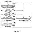
- FIG. 11 shows process contents in still image photographing when the camera mode is set by operating the camera key 46a of the various keys 46.
- An AE process is first executed at a focal length corresponding to the currently selected zoom position of the camera 48 (step D01).
- a correct exposure value is obtained to set an F-number and shutter speed, and an image is obtained from the CCD 75 on the basis of the F-number and shutter speed.
- a through image is displayed on the main display 45 or sub-display 50 (step D02)
- whether the set key 46b or shutter key 46c of the various keys 46 is pressed is determined (step D03). This determination is repetitively executed, and the-flow waits until the set key 46b or shutter key 46c is operated.
- step D03 Whether the current correct exposure value has a sufficient luminance is determined from whether the correct exposure value (EV value) acquired in the AE process of immediately preceding step D01 is larger than a preset exposure threshold (EVth) (step D04).
- a predetermined in-focus position which corresponds to the current zoom position of the camera 48 and provides the depth of field as large as possible is so fixed and set as to set a state close to the pan-focus, (step D05).
- a so-called stop-down AE process of setting the F-number as large as possible from the correct exposure value obtained in immediately preceding step D01 and decreasing the shutter speed in correspondence with the F-number is executed (step D06).
- the cellular phone 40 then shifts to the image data recording/save state.
- step D09 After image data by image sensing is obtained (step D09), the image data obtained by photographing is recorded and saved as a file in the memory card 69 by the image processing unit 68 (step D10). A series of photographing processes end, and the flow returns to the process from step D01 again in order to prepare for the next photographing.
- step D04 If it is determined in step D04 that the correct exposure value is equal to or smaller than the preset exposure threshold and does not have any sufficient luminance, an AF process is performed to obtain an in-focus position so as to focus the lens to a predetermined focus area because stop-down for obtaining the pan-focus results in a dark image (step D07). At the same time, the F-number and shutter speed which have been acquired in the AE process of immediately preceding step D01 and provide correct exposure are determined (step D08). Thereafter, the cellular phone 40 shifts to the image data recording/save state.
- step D09 After image data by image sensing is obtained (step D09), the image data obtained by image sensing is recorded and saved as a file in the memory card 69 by the image processing unit 68 (step D10). A series of photographing processes end, and the flow returns to the process from step D01 again in order to prepare for the next photographing.
- the F-number when the F-number is set large for a fixed focus upon determining in the AE process that an image has a low brightness, a decrease in light quantity cannot be satisfactorily compensated for even by decreasing the shutter speed, resulting in a dark image.
- the AF process using correct exposure is preferentially executed.
- the outer appearance is basically the same as that in FIGS. 9A and 9B
- the electronic circuit configuration is basically the same as that in FIG. 10 .
- the same numerals denote the same parts, and an illustration and description thereof will be omitted.
- both a set key 46b and shutter key 46c of various keys 46 immediately execute photographing by stroke operation of one stroke.
- the following processes are basically executed by a controller 65 on the basis of a permanently stored program.
- FIG. 12 shows process contents in still image photographing when the camera mode is set by operating a camera key 46a of the various keys 46.
- An AE process is first executed at a focal length corresponding to the currently selected zoom position of a camera 48 (step E01).
- a correct exposure value is obtained to set an F-number and shutter speed, and an image is obtained from a CCD 75 on the basis of the F-number and shutter speed.
- step E02 While a through image is displayed on a main display 45 or sub-display 50 (step E02), whether the set key 46b or shutter key 46c of the various keys 46 is pressed (step E03), and whether movement of the zoom position by an optical lens system 74 is designated with the " ⁇ " key or " ⁇ ” key of a ring key 46d of the various keys 46 (step E04) are sequentially determined. This determination is repetitively executed, and the flow waits until the set key 46b or shutter key 46c is operated or the " ⁇ " key or " ⁇ ” key of the ring key 46d is operated.
- step E04 If the " ⁇ " key or " ⁇ ” key of the ring key 46d is operated, this operation is determined in step E04.
- a motor 73 drives the optical lens system 74 to execute zoom-up or zoom-down in accordance with the operation contents (step E05), and the flow returns to the process from step E01 again.
- step E03 Whether the pan-focus effect can be obtained in terms of the depth of field is determined from whether a focal length (f) corresponding to the current zoom position is smaller than a preset focal length threshold (fth) (step E06).
- a predetermined in-focus position which corresponds to the current zoom position of the camera 48 and provides the depth of field as large as possible is so fixed and set as to set a state close to the pan-focus, (step E07).
- a so-called stop-down AE process of setting the F-number as large as possible from the correct exposure value obtained in immediately preceding step E01 and decreasing the shutter speed in correspondence with the F-number is executed (step E08).
- the cellular phone 40 then shifts to the image data recording/save state.
- step E11 After image data by image sensing is obtained (step E11), the image data obtained by photographing is recorded and saved as a file in a memory card 69 by an image processing unit 68 (step E12). A series of photographing processes end, and the flow returns to the process from step E01 again in order to prepare for the next photographing.
- step E06 If it is determined in step E06 that the current focal length is equal to or larger than the preset focal length threshold and no pan-focus effect can be obtained by setting a large depth of field, an AF process is performed to obtain an in-focus position so as to focus the lens to a predetermined focus area (step E09). At the same time, the F-number and shutter speed which have been acquired in the AE process of immediately preceding step E01 and provide correct exposure are determined (step E10). The cellular phone 40 then shifts to the image data recording/save state.
- step E11 After image data by image sensing is obtained (step E11), the image data obtained by photographing is recorded and saved as a file in the memory card 69 by the image processing unit 68 (step E12). A series of photographing processes end, and the flow returns to the process from step E01 again in order to prepare for the next photographing.
- the outer appearance is basically the same as that in FIGS. 9A and 9B
- the electronic circuit configuration is basically the same as that in FIG. 10 .
- the same numerals denote the same parts, and an illustration and description thereof will be omitted.
- both a set key 46b and shutter key 46c of various keys 46 immediately execute photographing by one stroke operation.
- the following processes are basically executed by a controller 65 on the basis of a permanently stored program.
- FIG. 13 shows process contents in still image photographing when the camera mode is set by operating a camera key 46a of the various keys 46.
- Whether a manual exposure mode has been set by user's mode setting is determined (step F01). If the manual exposure mode is set, an exposure value corresponding to manual operation by the user with a ring key 46d of the various keys 46 is set (step F02). If no manual exposure mode is set, an AE process is executed at a focal length corresponding to the currently selected zoom position of a camera 48 (step F03).
- An image is obtained from a CCD 75 on the basis of the F-number and shutter speed corresponding to the exposure state. While a through image is displayed on a main display 45 -or sub-display 50 (step F04), whether the set key 46b or shutter key 46c of the various keys 46 is pressed (step F05), and whether setting change operation associated with exposure is done (step F06) are sequentially determined. This determination is repetitively executed, and the flow waits until the set key 46b or shutter key 46c is operated or exposure change setting operation is done.
- step F06 An exposure setting change which includes a process of changing the exposure mode to AE or manual exposure and corresponds to operation contents is properly executed (step F07), and the flow returns to the process from step F01 again.
- step F05 If the set key 46b or shutter key 46c is operated, this operation is determined in step F05. Whether the manual exposure mode is set by user's mode setting is determined (step F08).
- a predetermined in-focus position which corresponds to the current zoom position of the camera 48 and provides the depth of field as large as possible is so fixed and set as to set a state close to the pan-focus, (step F11).
- a so-called stop-down AE process of setting the F-number as large as possible from the correct exposure value obtained in immediately preceding step F03 and decreasing the shutter speed in correspondence with the F-number is executed (step F12).
- the cellular phone 40 then shifts to the image data recording/save state.
- step F13 After image data by image sensing is obtained (step F13), the image data obtained by photographing is recorded and saved as a file in a memory card 69 by an image processing unit 68 (step F14). A series of photographing processes end, and the flow returns to the process from step F01 again in order to prepare for the next photographing.
- step F08 If it is determined in step F08 that the manual exposure mode is set and the user has arbitrarily set exposure conditions, an AF process is performed to obtain an in-focus position so as to focus the lens to a predetermined focus area because stop-down operation performed to obtain the pan-focus effect changes the exposure conditions set by the user (step F09). At the same time, the F-number and shutter speed which have been set by the manual exposure process in immediately preceding step F02 are determined (step F10). The cellular phone 40 then shifts to the image data recording/save state.
- step F13 After image data by image sensing is obtained (step F13), the image data obtained by photographing is recorded and saved as a file in the memory card 69 by the image processing unit 68 (step F14). A series of photographing processes end, and the flow returns to the process from step F01 again in order to prepare for the next photographing.
- the exposure value set by the user may change by setting a large F-number in order to obtain the pan-focus effect.
- the autofocus process is preferentially executed instead of the fixed focus without changing user's photographing purpose.
- the present invention is applied to a digital still camera.
- the present invention is applied to a CDMA cellular phone with a camera function.
- the present invention is not limited to them, and can also be applied to a PDA (Personal Digital Assistants) with a camera function, a mobile computer, a video movie camera capable of still image photographing, and a (still) camera using a silver halide film.
- PDA Personal Digital Assistants
- the first and second examples and the embodiment of the invention can also be applied to a CDMA cellular phone with a camera function, and the third to fifth examples can also be applied to a digital camera.
- the set key 46b or shutter key 46c of a CDMA cellular phone with a camera function is designed to operate by two stroke operations.
- “half stroke” and “full stroke” are determined, similar to the digital camera.
- the first to third embodiments can be applied to the CDMA cellular phone with the camera function.
- step D03, E03, and F05 determination (steps D03, E03, and F05) of shutter key operation of the CDMA cellular phone with the camera function is replaced with determination of a full stroke of the shutter key of a digital camera.
- the third to fifth examples can - be applied to the digital camera.
- the first and second examples and the embodiment of the invention adopt two, near-view and distant-view fixed-focus ranges, and which of the ranges is set is determined.
- the third to fifth examples may similarly adopt a plurality of fixed-focus ranges, and the determination method is not particularly limited.
Landscapes
- Engineering & Computer Science (AREA)
- Multimedia (AREA)
- Signal Processing (AREA)
- Studio Devices (AREA)
- Focusing (AREA)
- Automatic Focus Adjustment (AREA)
- Exposure Control For Cameras (AREA)
- Lens Barrels (AREA)
Claims (13)
- Bilderfassungsvorrichtung, die umfasst:eine Fotografiereinheit, die eine Autofokus-Funktion hat und einen Fotografiervorgang zum Erzeugen eines Objektbildes durchführt;eine Bestimmungseinheit (46b, 46c), die zwei Betätigungshübe hat und bei einer Betätigung mit einem ersten Hub Autofokus und bei einer Betätigung mit einem zweiten Hub Fotografieren bestimmt;eine Erfassungseinheit (225, 655), die vorgegebene Betätigungszustände mit dem ersten Hub und dem zweiten Hub erfasst, die durch die Bestimmungseinheit bestimmt werden; undeine Autofokus-Steuereinheit (22), die die Fotografiereinheit veranlasst, eine Betätigung unter Verwendung der Autofokus-Funktion zu einem Zeitpunkt zu beginnen, zu dem die Erfassungseinheit den Betätigungszustand mit dem ersten Hub erfasst,gekennzeichnet durcheine Feststelleinheit (22), die zu einem Zeitpunkt, zu dem die Erfassungseinheit den Betätigungszustand mit dem zweiten Hub erfasst, feststellt, ob die durch die Fotografiereinheit begonnene Betätigung unter Verwendung der Autofokus-Funktion abgeschlossen worden ist oder nicht; undeine Fokus-Steuereinheit (227, 657), die die Fotografiereinheit auf eine Festfokus-Position einstellt, in der eine vorgegebene Schärfentiefe erreicht wird, wenn die Feststelleinheit feststellt, dass die durch die Fotografiereinheit begonnene Betätigung unter Verwendung der Autofokus-Funktion nicht abgeschlossen worden ist.
- Bilderfassungsvorrichtung nach Anspruch 1, die des Weiteren eine Fotografier-Steuereinheit umfasst, die die Fotografiereinheit veranlasst, sofort den Fotografiervorgang zu beginnen, ohne die Fotografiereinheit auf die Festfokus-Position einzustellen, wenn die Feststelleinheit feststellt, dass die Betätigung unter Verwendung der Autofokus-Funktion der Fotografiereinheit abgeschlossen worden ist.
- Bilderfassungsvorrichtung nach Anspruch 2, wobei die Fotografier-Steuereinheit die Fotografiereinheit veranlasst, die Fotografierbetätigung unmittelbar nach Einstellen der Fotografiereinheit auf die Festfokus-Position durch die Fokus-Steuereinheit zu beginnen.
- Bilderfassungsvorrichtung nach Anspruch 1, die des Weiteren eine Fokusbereich-Bestimmungseinheit umfasst, die einen Festfokusbereich, der das Objekt-Bild enthält, aus einer Vielzahl von Festfokus-Bereichen bestimmt, wobei die Fokus-Steuereinheit den durch die Fokusbereich-Bestimmungseinheit hergestellten Festfokus-Bereich beim Umschalten auf die Festfokus-Position und Auswählen derselben auswählt.
- Bilderfassungsvorrichtung nach Anspruch 4, wobei die Fotografiereinheit eine Funktion für automatischen Weißabgleich hat, durch die Farbtemperaturanpassung entsprechend einer Lichtquelle durchgeführt wird, und die Fokusbereich-Bestimmungseinheit den Festfokus-Bereich, der das Objektbild enthält, entsprechend einem Ergebnis von FarbtemperaturAnpassung mittels der Funktion für automatischen Weißabgleich bestimmt.
- Bilderfassungsvorrichtung nach Anspruch 4, die des Weiteren eine Mitteilungseinheit umfasst, die eine Mitteilung über ein Ergebnis des Bestimmens des Festfokus-Bereiches, der das Objektbild enthält, durch die Fokusbereich-Bestimmungseinheit ausgibt.
- Fotografierverfahren, das umfasst:einen Fotografierschritt, in dem Autofokus durch eine Betätigung mit einem ersten Hub einer Verschlusstaste ausgeführt wird, die eine Autofokus-Funktion hat und in zwei Hüben arbeitet, und durch eine Betätigung mit einem zweiten Hub fotografiert wird;eine Erfassungsschritt, in dem vorgegebene Betätigungszustände mit dem ersten Hub und dem zweiten Hub erfasst werden, die durch die Verschlusstaste bestimmt werden; undeinen Autofokus-Steuerschritt, in dem eine Betätigung unter Verwendung der Autofokus-Funktion zu einem Zeitpunkt begonnen wird, zu dem der Betätigungszustand mit dem ersten Hub in dem Erfassungsschritt erfasst wird,gekennzeichnet durcheinen Feststellschritt, in dem zu einem Zeitpunkt, zu dem der Betätigungszustand mit dem zweiten Hub in dem Erfassungsschritt erfasst wird, festgestellt wird, ob die Betätigung unter Verwendung der Autofokus-Funktion abgeschlossen worden ist oder nicht, undeinen Fokus-Steuerschritt, in dem eine Festfokus-Position eingestellt wird, bei der eine vorgegebene Schärfentiefe hergestellt wird, wenn in dem Feststellschritt festgestellt wird, dass der Vorgang unter Verwendung der Autofokus-Funktion nicht abgeschlossen worden ist.
- Fotografierverfahren nach Anspruch 7, das des Weiteren einen Fotografier-Steuerschritt umfasst, in dem veranlasst wird, dass eine Fotografierbetätigung sofort ohne Einstellen der Festfokus-Position begonnen wird, wenn in dem Feststellschritt festgestellt wird, dass der Vorgang unter Verwendung der Autofokus-Funktion abgeschlossen worden ist.
- Fotografierverfahren nach Anspruch 8, wobei in dem Fotografier-Steuerschritt die Fotografierbetätigung unmittelbar nach Einstellen der Festfokus-Position in dem Fokus-Steuerschritt durchgeführt wird.
- Fotografierverfahren nach Anspruch 7, das des Weiteren einen Fokusbereich-Bestimmungsschritt umfasst, in dem ein Festfokus-Bereich, der ein Objektbild enthält, aus einer Vielzahl von Festfokus-Bereichen in dem Fokus-Steuerschritt bestimmt wird, wobei der in dem Fokusbereich-Bestimmungsschritt erzeugte Festfokus-Bereich beim Umschalten auf die Festfokus-Position und Auswahl derselben ausgewählt wird.
- Fotografierverfahren nach Anspruch 10, wobei der Fotografierschritt eine Funktion für automatischen Weißabgleich aufweist, mit der Farbtemperaturanpassung entsprechend einer Lichtquelle durchgeführt wird, und in dem Fokusbereich-Bestimmungsschritt der Festfokus-Bereich, der das Objektbild enthält, entsprechend einem Ergebnis von Farbtemperatur-Anpassung mittels der Funktion für automatischen Weißabgleich bestimmt wird.
- Fotografierverfahren nach Anspruch 10, das des Weiteren einen Mitteilungsschritt umfasst, in dem eine Mitteilung über ein Ergebnis des Bestimmens des Festfokus-Bereiches, der das Objektbild enthält, in dem Fokusbereich-Bestimmungsschritt ausgegeben wird.
- Computerprogrammerzeugnis, das ein computerlesbares Medium umfasst, auf dem computerlesbarer Programmcode enthalten ist, wobei der Programmcode zum Ausführen aller Schritte nach einem der Ansprüche 7 bis 12 eingerichtet ist.
Applications Claiming Priority (3)
| Application Number | Priority Date | Filing Date | Title |
|---|---|---|---|
| JP2003285925 | 2003-08-04 | ||
| JP2004060990A JP2005070738A (ja) | 2003-08-04 | 2004-03-04 | 撮像装置、撮像方法及びプログラム |
| PCT/JP2004/011422 WO2005013606A2 (en) | 2003-08-04 | 2004-08-03 | Image sensing apparatus, image sensing method, and recording medium which records photographing method |
Publications (2)
| Publication Number | Publication Date |
|---|---|
| EP1661394A2 EP1661394A2 (de) | 2006-05-31 |
| EP1661394B1 true EP1661394B1 (de) | 2012-09-19 |
Family
ID=34117943
Family Applications (1)
| Application Number | Title | Priority Date | Filing Date |
|---|---|---|---|
| EP04771409A Expired - Lifetime EP1661394B1 (de) | 2003-08-04 | 2004-08-03 | Bilderfassungsvorrichtung, bilderfassungsverfahren und aufzeichnungsmedium, das ein fotografierverfahren aufzeichnet |
Country Status (6)
| Country | Link |
|---|---|
| US (2) | US20050041136A1 (de) |
| EP (1) | EP1661394B1 (de) |
| JP (1) | JP2005070738A (de) |
| KR (1) | KR100736482B1 (de) |
| TW (1) | TWI270738B (de) |
| WO (1) | WO2005013606A2 (de) |
Families Citing this family (35)
| Publication number | Priority date | Publication date | Assignee | Title |
|---|---|---|---|---|
| JP2005070738A (ja) * | 2003-08-04 | 2005-03-17 | Casio Comput Co Ltd | 撮像装置、撮像方法及びプログラム |
| JP4607448B2 (ja) * | 2003-11-14 | 2011-01-05 | 富士通株式会社 | 電子装置、撮影制御方法、撮影制御プログラム及び集積回路 |
| US8587849B2 (en) * | 2004-04-05 | 2013-11-19 | Hewlett-Packard Development Company, L.P. | Imaging systems, imaging device analysis systems, imaging device analysis methods, and light beam emission methods |
| US8705151B2 (en) * | 2004-04-05 | 2014-04-22 | Hewlett-Packard Development Company, L.P. | Imaging device calibration methods, imaging device calibration instruments, imaging devices, and articles of manufacture |
| US8634014B2 (en) * | 2004-04-05 | 2014-01-21 | Hewlett-Packard Development Company, L.P. | Imaging device analysis systems and imaging device analysis methods |
| JP4591325B2 (ja) * | 2005-01-28 | 2010-12-01 | カシオ計算機株式会社 | 撮像装置及びプログラム |
| JP4193804B2 (ja) * | 2005-02-03 | 2008-12-10 | カシオ計算機株式会社 | 撮像装置、画像記憶装置、撮像方法、記憶方法及びプログラム |
| JP2006337388A (ja) * | 2005-05-31 | 2006-12-14 | Eastman Kodak Co | 撮像装置および撮影方法 |
| JP4670547B2 (ja) * | 2005-08-23 | 2011-04-13 | 沖電気工業株式会社 | 生体認証装置および生体認証方法 |
| JP4957943B2 (ja) * | 2005-09-07 | 2012-06-20 | カシオ計算機株式会社 | 撮像装置及びそのプログラム |
| US7398016B2 (en) * | 2005-11-04 | 2008-07-08 | Seiko Epson Corporation | Backlight compensation using threshold detection |
| US20070188651A1 (en) * | 2006-02-14 | 2007-08-16 | Akihiro Machida | Automatically capturing focused images obtained through unguided manual focus adjustment |
| JP4764774B2 (ja) * | 2006-05-31 | 2011-09-07 | Hoya株式会社 | 焦点調節装置を備えたカメラ |
| JP4858849B2 (ja) | 2007-05-18 | 2012-01-18 | カシオ計算機株式会社 | 撮像装置及びそのプログラム |
| JP5065165B2 (ja) * | 2008-06-11 | 2012-10-31 | 三洋電機株式会社 | 電子カメラ |
| US9214004B2 (en) | 2008-12-18 | 2015-12-15 | Vmware, Inc. | Watermarking and scalability techniques for a virtual desktop planning tool |
| US8788079B2 (en) | 2010-11-09 | 2014-07-22 | Vmware, Inc. | Monitoring audio fidelity and audio-video synchronization |
| US9674562B1 (en) | 2008-12-18 | 2017-06-06 | Vmware, Inc. | Quality evaluation of multimedia delivery in cloud environments |
| JP5426960B2 (ja) * | 2009-08-04 | 2014-02-26 | キヤノン株式会社 | 撮像装置及び撮像方法 |
| US9336117B2 (en) | 2010-11-09 | 2016-05-10 | Vmware, Inc. | Remote display performance measurement triggered by application display upgrade |
| JP5794661B2 (ja) * | 2010-12-20 | 2015-10-14 | キヤノン株式会社 | 光学機器 |
| US9413944B2 (en) * | 2011-04-22 | 2016-08-09 | Blackberry Limited | Apparatus and method for controlling a camera in an electronic device |
| EP2704432A4 (de) * | 2011-06-23 | 2014-04-02 | Huawei Device Co Ltd | Verfahren zur videoaufnahme eines mobilen endgeräts und system dafür |
| US9787397B2 (en) | 2011-07-26 | 2017-10-10 | Abl Ip Holding Llc | Self identifying modulated light source |
| US9444547B2 (en) | 2011-07-26 | 2016-09-13 | Abl Ip Holding Llc | Self-identifying one-way authentication method using optical signals |
| US8334898B1 (en) | 2011-07-26 | 2012-12-18 | ByteLight, Inc. | Method and system for configuring an imaging device for the reception of digital pulse recognition information |
| US8964016B2 (en) | 2011-07-26 | 2015-02-24 | ByteLight, Inc. | Content delivery based on a light positioning system |
| JP5948076B2 (ja) * | 2011-08-23 | 2016-07-06 | オリンパス株式会社 | フォーカス制御装置、内視鏡装置及びフォーカス制御方法 |
| WO2015077767A1 (en) | 2013-11-25 | 2015-05-28 | Daniel Ryan | System and method for communication with a mobile device via a positioning system including rf communication devices and modulated beacon light sources |
| US10136061B2 (en) | 2015-01-30 | 2018-11-20 | Microsoft Technology Licensing, Llc | Automatic processing of automatic image capture parameter adjustment |
| CN108833617B (zh) * | 2015-06-30 | 2020-09-29 | Oppo广东移动通信有限公司 | 移动终端 |
| KR20170110837A (ko) * | 2016-03-24 | 2017-10-12 | 주식회사 하이딥 | 촬영 모드 전환이 용이한 모바일 단말 및 촬영 모드 전환 방법 |
| EP3480641A4 (de) * | 2016-06-30 | 2020-02-26 | Nikon Corporation | Kamera |
| US10984219B2 (en) * | 2019-07-19 | 2021-04-20 | Idmission, Llc | Fingerprint processing with liveness detection |
| JP7594539B2 (ja) * | 2019-09-26 | 2024-12-04 | 株式会社小糸製作所 | ゲーティングカメラ、自動車、車両用灯具、画像処理装置、画像処理方法 |
Family Cites Families (35)
| Publication number | Priority date | Publication date | Assignee | Title |
|---|---|---|---|---|
| JPS5962810A (ja) | 1982-10-04 | 1984-04-10 | Sony Corp | オ−トフオ−カス装置 |
| JPS63301928A (ja) | 1987-06-02 | 1988-12-08 | Canon Inc | オ−トフオ−カス装置 |
| US4985723A (en) * | 1988-05-16 | 1991-01-15 | Minolta Camera Kabushiki Kaisha | Photographic camera |
| JPH0335229A (ja) | 1989-06-30 | 1991-02-15 | Casio Comput Co Ltd | 多重焦点撮影機能を有するカメラ |
| JP2749961B2 (ja) * | 1990-06-14 | 1998-05-13 | キヤノン株式会社 | 撮像装置 |
| JP2882108B2 (ja) | 1991-08-21 | 1999-04-12 | 松下電器産業株式会社 | オートフォーカス装置 |
| JPH05161101A (ja) | 1991-12-10 | 1993-06-25 | Matsushita Electric Ind Co Ltd | カメラ一体型磁気録画再生装置 |
| JPH05249364A (ja) * | 1992-03-06 | 1993-09-28 | Canon Inc | カメラ及びズ−ムレンズ |
| JPH0667256A (ja) | 1992-08-19 | 1994-03-11 | Nikon Corp | カメラの制御装置 |
| JPH06222259A (ja) | 1993-01-23 | 1994-08-12 | Asahi Optical Co Ltd | 自動焦点カメラ |
| JPH06258569A (ja) | 1993-03-08 | 1994-09-16 | West Electric Co Ltd | オートフォーカス装置 |
| JPH0756227A (ja) | 1993-08-16 | 1995-03-03 | Fuji Photo Film Co Ltd | カメラ |
| JP3368041B2 (ja) * | 1994-04-26 | 2003-01-20 | キヤノン株式会社 | 撮像装置 |
| US5751354A (en) * | 1994-04-28 | 1998-05-12 | Canon Kabushiki Kaisha | Image sensing apparatus and method with exposure performed based on focus evaluation values |
| US5701520A (en) * | 1994-10-13 | 1997-12-23 | Fuji Photo Optical Co., Ltd. | Camera |
| US6833863B1 (en) * | 1998-02-06 | 2004-12-21 | Intel Corporation | Method and apparatus for still image capture during video streaming operations of a tethered digital camera |
| US6493828B1 (en) * | 1998-08-31 | 2002-12-10 | Sony Corporation | Information processing apparatus, information processing method, and program storage medium |
| JP4164202B2 (ja) * | 1998-10-08 | 2008-10-15 | キヤノン株式会社 | 電子機器、電子機器の駆動方法、及びコンピュータ読み取り可能な記憶媒体 |
| US7233357B1 (en) * | 1998-12-22 | 2007-06-19 | Canon Kabushiki Kaisha | Image pickup apparatus with image evaluation |
| JP2002090823A (ja) * | 2000-09-12 | 2002-03-27 | Canon Inc | 自動焦点カメラ及びその撮影方法 |
| JP2003101853A (ja) | 2001-09-25 | 2003-04-04 | Konica Corp | デジタルカメラ |
| JP2003140025A (ja) | 2001-11-01 | 2003-05-14 | Olympus Optical Co Ltd | 撮像装置 |
| US6549729B1 (en) * | 2001-11-28 | 2003-04-15 | Hewlett Packard Development Company, L.P. | Camera that operates in accordance with the speed requirements of the photographer |
| JP4436583B2 (ja) * | 2001-12-19 | 2010-03-24 | 富士フイルム株式会社 | デジタルカメラ |
| US20030142228A1 (en) * | 2002-01-25 | 2003-07-31 | Matthew Flach | Apparatus and method for power saving and rapid response in a digital imaging device |
| JP2003262786A (ja) * | 2002-03-08 | 2003-09-19 | Casio Comput Co Ltd | 撮像装置及びその自動合焦方法 |
| JP4056267B2 (ja) * | 2002-03-15 | 2008-03-05 | 株式会社リコー | 撮像装置 |
| JP2004023205A (ja) | 2002-06-13 | 2004-01-22 | Sony Corp | 色信号処理回路、色信号処理方法、及びカメラ装置 |
| JP4146180B2 (ja) | 2002-07-08 | 2008-09-03 | 富士フイルム株式会社 | カメラ |
| JP2005070738A (ja) * | 2003-08-04 | 2005-03-17 | Casio Comput Co Ltd | 撮像装置、撮像方法及びプログラム |
| JP4607448B2 (ja) * | 2003-11-14 | 2011-01-05 | 富士通株式会社 | 電子装置、撮影制御方法、撮影制御プログラム及び集積回路 |
| US20050275742A1 (en) * | 2004-06-09 | 2005-12-15 | Baron John M | Autofocus after image capture |
| JP4591325B2 (ja) * | 2005-01-28 | 2010-12-01 | カシオ計算機株式会社 | 撮像装置及びプログラム |
| JP4193804B2 (ja) * | 2005-02-03 | 2008-12-10 | カシオ計算機株式会社 | 撮像装置、画像記憶装置、撮像方法、記憶方法及びプログラム |
| JP4858849B2 (ja) * | 2007-05-18 | 2012-01-18 | カシオ計算機株式会社 | 撮像装置及びそのプログラム |
-
2004
- 2004-03-04 JP JP2004060990A patent/JP2005070738A/ja active Pending
- 2004-08-02 US US10/910,763 patent/US20050041136A1/en not_active Abandoned
- 2004-08-03 WO PCT/JP2004/011422 patent/WO2005013606A2/en not_active Ceased
- 2004-08-03 EP EP04771409A patent/EP1661394B1/de not_active Expired - Lifetime
- 2004-08-03 KR KR1020067002375A patent/KR100736482B1/ko not_active Expired - Fee Related
- 2004-08-04 TW TW093123299A patent/TWI270738B/zh not_active IP Right Cessation
-
2008
- 2008-12-17 US US12/336,918 patent/US7995132B2/en not_active Expired - Fee Related
Also Published As
| Publication number | Publication date |
|---|---|
| JP2005070738A (ja) | 2005-03-17 |
| KR100736482B1 (ko) | 2007-07-06 |
| KR20060039931A (ko) | 2006-05-09 |
| WO2005013606A2 (en) | 2005-02-10 |
| US20090102962A1 (en) | 2009-04-23 |
| US20050041136A1 (en) | 2005-02-24 |
| US7995132B2 (en) | 2011-08-09 |
| TW200519518A (en) | 2005-06-16 |
| TWI270738B (en) | 2007-01-11 |
| EP1661394A2 (de) | 2006-05-31 |
| HK1095236A1 (zh) | 2007-04-27 |
| WO2005013606A3 (en) | 2005-08-18 |
Similar Documents
| Publication | Publication Date | Title |
|---|---|---|
| EP1661394B1 (de) | Bilderfassungsvorrichtung, bilderfassungsverfahren und aufzeichnungsmedium, das ein fotografierverfahren aufzeichnet | |
| EP1377038B1 (de) | Digitale Kamera und Verfahren zur Erkennung der fotografischen Richtung | |
| US8558923B2 (en) | Image capturing apparatus and method for selective real time focus/parameter adjustment | |
| CN100539644C (zh) | 显示调焦信息的照相设备 | |
| JP2008288975A (ja) | 撮像装置、撮像方法および撮像プログラム | |
| JP7795583B2 (ja) | 画像処理装置、画像処理方法及び画像処理プログラム | |
| WO2020066317A1 (ja) | 撮影装置、撮影方法、及びプログラム | |
| JP4341407B2 (ja) | 撮像投影装置 | |
| JP4626637B2 (ja) | 撮像装置及びプログラム | |
| CN100527790C (zh) | 图像感应装置以及图像感应方法 | |
| JP3891147B2 (ja) | 動画編集装置、動画編集方法及びプログラム | |
| JP4395614B2 (ja) | 電子機器、電源制御方法及びプログラム | |
| JPWO2020161969A1 (ja) | 画像処理装置、撮影装置、画像処理方法及び画像処理プログラム | |
| HK1095236B (en) | Image sensing apparatus and image sensing method | |
| JP2008134646A (ja) | 撮像装置、撮像方法及びプログラム | |
| JP2003274049A (ja) | 通信装置 | |
| US7965889B2 (en) | Imaging apparatus, imaging method, program and recording medium | |
| KR20120060677A (ko) | 휴대단말기의 영상 촬영 방법 | |
| TWI249341B (en) | Method of motion terminal having photographic device to adjust the photographic-control parameters quickly | |
| JP2005191978A (ja) | 携帯電子機器、撮影方法及びプログラム | |
| JP2006154524A (ja) | 撮像装置、および合焦位置探索方法 | |
| JP2006013784A (ja) | デジタルカメラ | |
| KR20070010773A (ko) | 디지털 이미지 리사이즈 방법 및 이를 수행하는 디지털이미지 처리장치 | |
| JP2012105220A (ja) | 撮像装置、動作制御方法及びプログラム | |
| JP2006163064A (ja) | 撮像装置、および合焦位置探索方法 |
Legal Events
| Date | Code | Title | Description |
|---|---|---|---|
| PUAI | Public reference made under article 153(3) epc to a published international application that has entered the european phase |
Free format text: ORIGINAL CODE: 0009012 |
|
| 17P | Request for examination filed |
Effective date: 20060210 |
|
| AK | Designated contracting states |
Kind code of ref document: A2 Designated state(s): DE FR GB |
|
| DAX | Request for extension of the european patent (deleted) | ||
| RBV | Designated contracting states (corrected) |
Designated state(s): DE FR GB |
|
| 17Q | First examination report despatched |
Effective date: 20071030 |
|
| GRAP | Despatch of communication of intention to grant a patent |
Free format text: ORIGINAL CODE: EPIDOSNIGR1 |
|
| GRAC | Information related to communication of intention to grant a patent modified |
Free format text: ORIGINAL CODE: EPIDOSCIGR1 |
|
| RIN1 | Information on inventor provided before grant (corrected) |
Inventor name: MIYATA, AKIRA C/O INTELLECTUAL PROPERTY DEPARTMENT Inventor name: ONOZAWA, MASARU C/O INTELLECTUAL PORPERTY DEPARTME |
|
| GRAS | Grant fee paid |
Free format text: ORIGINAL CODE: EPIDOSNIGR3 |
|
| GRAA | (expected) grant |
Free format text: ORIGINAL CODE: 0009210 |
|
| AK | Designated contracting states |
Kind code of ref document: B1 Designated state(s): DE FR GB |
|
| REG | Reference to a national code |
Ref country code: GB Ref legal event code: FG4D |
|
| REG | Reference to a national code |
Ref country code: DE Ref legal event code: R096 Ref document number: 602004039388 Country of ref document: DE Effective date: 20121115 |
|
| PLBE | No opposition filed within time limit |
Free format text: ORIGINAL CODE: 0009261 |
|
| STAA | Information on the status of an ep patent application or granted ep patent |
Free format text: STATUS: NO OPPOSITION FILED WITHIN TIME LIMIT |
|
| 26N | No opposition filed |
Effective date: 20130620 |
|
| REG | Reference to a national code |
Ref country code: DE Ref legal event code: R097 Ref document number: 602004039388 Country of ref document: DE Effective date: 20130620 |
|
| REG | Reference to a national code |
Ref country code: FR Ref legal event code: PLFP Year of fee payment: 13 |
|
| REG | Reference to a national code |
Ref country code: FR Ref legal event code: PLFP Year of fee payment: 14 |
|
| PGFP | Annual fee paid to national office [announced via postgrant information from national office to epo] |
Ref country code: FR Payment date: 20170628 Year of fee payment: 14 |
|
| PGFP | Annual fee paid to national office [announced via postgrant information from national office to epo] |
Ref country code: FR Payment date: 20170426 Year of fee payment: 14 |
|
| GBPC | Gb: european patent ceased through non-payment of renewal fee |
Effective date: 20180803 |
|
| PG25 | Lapsed in a contracting state [announced via postgrant information from national office to epo] |
Ref country code: FR Free format text: LAPSE BECAUSE OF NON-PAYMENT OF DUE FEES Effective date: 20180831 |
|
| PG25 | Lapsed in a contracting state [announced via postgrant information from national office to epo] |
Ref country code: GB Free format text: LAPSE BECAUSE OF NON-PAYMENT OF DUE FEES Effective date: 20180803 |
|
| PGFP | Annual fee paid to national office [announced via postgrant information from national office to epo] |
Ref country code: DE Payment date: 20200722 Year of fee payment: 17 |
|
| REG | Reference to a national code |
Ref country code: DE Ref legal event code: R119 Ref document number: 602004039388 Country of ref document: DE |
|
| PG25 | Lapsed in a contracting state [announced via postgrant information from national office to epo] |
Ref country code: DE Free format text: LAPSE BECAUSE OF NON-PAYMENT OF DUE FEES Effective date: 20220301 |