EP1604935A1 - Dispositif d'ascenseur et dispositif d'arret d'urgence pour ascenseur - Google Patents
Dispositif d'ascenseur et dispositif d'arret d'urgence pour ascenseur Download PDFInfo
- Publication number
- EP1604935A1 EP1604935A1 EP04721325A EP04721325A EP1604935A1 EP 1604935 A1 EP1604935 A1 EP 1604935A1 EP 04721325 A EP04721325 A EP 04721325A EP 04721325 A EP04721325 A EP 04721325A EP 1604935 A1 EP1604935 A1 EP 1604935A1
- Authority
- EP
- European Patent Office
- Prior art keywords
- car
- speed
- braking
- detecting
- elevator apparatus
- Prior art date
- Legal status (The legal status is an assumption and is not a legal conclusion. Google has not performed a legal analysis and makes no representation as to the accuracy of the status listed.)
- Granted
Links
Images


Classifications
-
- B—PERFORMING OPERATIONS; TRANSPORTING
- B66—HOISTING; LIFTING; HAULING
- B66B—ELEVATORS; ESCALATORS OR MOVING WALKWAYS
- B66B5/00—Applications of checking, fault-correcting, or safety devices in elevators
- B66B5/02—Applications of checking, fault-correcting, or safety devices in elevators responsive to abnormal operating conditions
- B66B5/16—Braking or catch devices operating between cars, cages, or skips and fixed guide elements or surfaces in hoistway or well
- B66B5/18—Braking or catch devices operating between cars, cages, or skips and fixed guide elements or surfaces in hoistway or well and applying frictional retarding forces
-
- B—PERFORMING OPERATIONS; TRANSPORTING
- B66—HOISTING; LIFTING; HAULING
- B66B—ELEVATORS; ESCALATORS OR MOVING WALKWAYS
- B66B5/00—Applications of checking, fault-correcting, or safety devices in elevators
- B66B5/02—Applications of checking, fault-correcting, or safety devices in elevators responsive to abnormal operating conditions
- B66B5/04—Applications of checking, fault-correcting, or safety devices in elevators responsive to abnormal operating conditions for detecting excessive speed
- B66B5/06—Applications of checking, fault-correcting, or safety devices in elevators responsive to abnormal operating conditions for detecting excessive speed electrical
Definitions
- the present invention relates to an elevator apparatus in which a car ascends and descends in a hoistway, and to a safety device for an elevator which forcibly stops a car that is ascending or descending at abnormal speed.
- a speed governor is often used in conventional elevator apparatuses to actuate a safety device mounted on an elevator car.
- Japanese Patent Application No. 2001-80840 discloses a speed governor which detects abnormalities in the speed at which a car is ascending or descending, and a safety device which presses a wedge against a car guide rail that guides the car to thereby keep the car from falling.
- a governor rope which moves in synchronism with the raising and lowering of the car, is wound around the sheave of the speed governor.
- Mounted on the car is a safety link which is connected to the governor rope and operatively coupled to the wedge of the car safety device.
- the speed governor Upon detecting a car speed abnormality, the speed governor locks up the governor rope. This lockup of the governor rope actuates the safety link, and the wedge is pressed against the car guide rail. The braking force generated by this pressing action keeps the car from falling.
- the time from the car speed abnormality detection to the braking force generation may become rather long due to, for example, a delay in the governor rope lockup operation, expansion or contraction of the governor rope, a delay in the operation of the safety link, and the like. Therefore, the speed of the car rises even higher by the time the braking force is generated, which means that even greater impact acts on the car upon braking. Further, this also results in an increase in the braking distance traveled by the car until it comes to a halt.
- the present invention is made to solve the problems described above. Therefore, it is an object of the invention to provide an elevator apparatus and a safety device for an elevator, which are capable of reducing the time it takes from the occurrence of an abnormality in the elevator apparatus to the generation of a braking force while preventing erroneous actuation.
- an elevator apparatus includes car speed detecting means for detecting a speed of a car, an output portion which outputs an actuation signal when the speed of the car detected by the car speed detecting means reaches a preset overspeed, braking means mounted on the car and having a braking member capable of moving into and away from contact with a car guide rail that guides ascent/descent of the car, for braking the car by pressing the braking member against the car guide rail upon input of the actuation signal, and transmitting means for transmitting the actuation signal from the output portion to the braking means.
- Fig. 1 is a schematic diagram showing an elevator apparatus according to Embodiment 1 of the present invention.
- a pair of car guide rails 2 are arranged within a hoistway 1.
- a car 3 is guided by the car guide rails 2 as it is raised and lowered in the hoistway 1.
- a hoisting machine (not shown) for raising and lowering the car 3 and a counterweight (not shown).
- a main rope 4 is wound around a drive sheave of the hoisting machine.
- the car 3 and the counterweight are suspended in the hoistway 1 by means of the main rope 4.
- Mounted to the car 3 are a pair of safety devices 5 opposed to the respective guide rails 2 and serving as braking means.
- the safety devices 5 are arranged on the underside of the car 3. Braking is applied to the car 3 upon actuating the safety devices 5.
- a governor 6 serving as a car speed detecting means for detecting the ascending/descending speed of the car 3.
- the governor 6 has a governor main body 7 and a governor sheave 8 rotatable with respect to the governor main body 7.
- a rotatable tension pulley 9 is arranged at a lower end portion of the hoistway 1. Wound between the governor sheave 8 and the tension pulley 9 is a governor rope 10 connected to the car 3.
- the connecting portion between the governor rope 10 and the car 3 undergoes vertical reciprocating motion as the car 3 travels. As a result, the governor sheave 8 and the tension pulley 9 are rotated at a speed corresponding to the ascending/descending speed of the car 3.
- the governor 6 is adapted to actuate a braking device of the hoisting machine when the ascending/descending speed of the car 3 has reached a preset first overspeed. Further, the governor 6 is provided with a switch portion 11 serving as an output portion through which an actuation signal is output to the safety devices 5 when the descending speed of the car 3 reaches a second overspeed (set overspeed) higher than the first overspeed.
- the switch portion 11 has a contact 16 which is mechanically opened and closed by means of an overspeed lever that is displaced according to the centrifugal force of the rotating governor sheave 8.
- the contact 16 is electrically connected to a battery 12, which is an uninterruptible power supply capable of feeding power even in the event of a power failure, and to a control panel 13 that controls the drive of an elevator, through a power supply cable 14 and a connection cable 15, respectively.
- a control cable (movable cable) is connected between the car 3 and the control panel 13.
- the control cable includes, in addition to multiple power lines and signal lines, an emergency stop wiring 17 electrically connected between the control panel 13 and each safety device 5.
- an emergency stop wiring 17 electrically connected between the control panel 13 and each safety device 5.
- Fig. 2 is a front view showing the safety device 5 of Fig. 1
- Fig. 3 is a front view showing the safety device 5 of Fig. 2 that has been actuated.
- a support member 18 is fixed in position below the car 3.
- the safety device 5 is fixed to the support member 18.
- each safety device 5 includes a pair of actuator portions 20, which are connected to a pair of wedges 19 serving as braking members and capable of moving into and away from contact with the car guide rail 2 to displace the wedges 19 with respect to the car 3, and a pair of guide portions 21 which are fixed to the support member 18 and guide the wedges 19 displaced by the actuator portions 20 into contact with the car guide rail 2.
- the pair of wedges 19, the pair of actuator portions 20, and the pair of guide portions 21 are each arranged symmetrically on both sides of the car guide rail 2.
- Each guide portion 21 has an inclined surface 22 inclined with respect to the car guide rail 2 such that the distance between it and the car guide rail 2 decreases with increasing proximity to its upper portion.
- the wedge 19 is displaced along the inclined surface 22.
- Each actuator portion 20 includes a spring 23 serving as an urging portion that urges the wedge 19 upward toward the guide portion 21 side, and an electromagnet 24 which, when supplied with electric current, generates an electromagnetic force for displacing the wedge 19 downward away from the guide member 21 against the urging force of the spring 23.
- the spring 23 is connected between the support member 18 and the wedge 19.
- the electromagnet 24 is fixed to the support member 18.
- the emergency stop wiring 17 is connected to the electromagnet 24.
- Fixed to each wedge 19 is a permanent magnet 25 opposed to the electromagnet 24.
- the supply of electric current to the electromagnet 24 is performed from the battery 12 (see Fig. 1) by the closing of the contact 16 (see Fig. 1).
- the safety device 5 is actuated as the supply of electric current to the electromagnet 24 is cut off by the opening of the contact 16 (see Fig. 1). That is, the pair of wedges 19 are displaced upward due to the elastic restoring force of the spring 23 to be pressed against the car guide rail 2.
- the contact 16 remains closed during normal operation. Accordingly, power is supplied from the battery 12 to the electromagnet 24.
- the wedge 19 is attracted and held onto the electromagnet 24 by the electromagnetic force generated upon this power supply, and thus remains separated from the car guide rail 2 (Fig. 2).
- the wedges 19 are displaced further upward as they come into contact with the car guide rail 2, to become wedged in between the car guide rail 2 and the guide portions 21. A large frictional force is thus generated between the car guide rail 2 and the wedges 19, braking the car 3 (Fig. 3).
- the car 3 is raised while supplying electric current to the electromagnet 24 by the closing of the contact 16. As a result, the wedges 19 are displaced downward, thus separating from the car guide rail 2.
- the switch portion 11 connected to the battery 12 and each safety device 5 are electrically connected to each other, whereby an abnormality in the speed of the car 3 detected by the governor 6 can be transmitted as an electrical actuation signal from the switch portion 11 to each safety device 5, making it possible to brake the car 3 in a short time after detecting an abnormality in the speed of the car 3.
- the braking distance of the car 3 can be reduced.
- synchronized actuation of the respective safety devices 5 can be readily effected, making it possible to stop the car 3 in a stable manner.
- each safety device 5 is actuated by the electrical actuation signal, thus preventing the safety device 5 from being erroneously actuated due to shaking of the car 3 or the like.
- each safety device 5 has the actuator portions 20 which displace the wedge 19 upward toward the guide portion 21 side, and the guide portions 21 each including the inclined surface 22 to guide the upwardly displaced wedge 19 into contact with the car guide rail 2, whereby the force with which the wedge 19 is pressed against the car guide rail 2 during descending movement of the car 3 can be increased with reliability.
- each actuator portion 20 has a spring 23 that urges the wedge 19 upward, and an electromagnet 24 for displacing the wedge 19 downward against the urging force of the spring 23, thereby enabling displacement of the wedge 19 by means of a simple construction.
- Fig. 4 is a schematic diagram showing an elevator apparatus according to Embodiment 2 of the present invention.
- the car 3 has a car main body 27 provided with a car entrance 26, and a car door 28 that opens and closes the car entrance 26.
- a car speed sensor 31 serving as car speed detecting means for detecting the speed of the car 3.
- Mounted inside the control panel 13 is an output portion 32 electrically connected to the car speed sensor 31.
- the battery 12 is connected to the output portion 32 through the power supply cable 14. Electric power used for detecting the speed of the car 3 is supplied from the output portion 32 to the car speed sensor 31.
- the output portion 32 is input with a speed detection signal from the car speed sensor 31.
- each safety device 33 Mounted on the underside of the car 3 are a pair of safety devices 33 serving as braking means for braking the car 3.
- the output portion 32 and each safety device 33 are electrically connected to each other through the emergency stop wiring 17.
- an actuation signal which is the actuating power, is output to each safety device 33.
- the safety devices 33 are actuated upon input of this actuation signal.
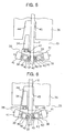
- Fig. 5 is a front view showing the safety device 33 of Fig. 4
- Fig. 6 is a front view showing the safety device 33 of Fig. 5 that has been actuated.
- the safety device 33 has a wedge 34 serving as a braking member and capable of moving into and away from contact with the car guide rail 2, an actuator portion 35 connected to a lower portion of the wedge 34, and a guide portion 36 arranged above the wedge 34 and fixed to the car 3.
- the wedge 34 and the actuator portion 35 are capable of vertical movement with respect to the guide portion 36. As the wedge 34 is displaced upward with respect to the guide portion 36, that is, toward the guide portion 36 side, the wedge 34 is guided by the guide portion 36 into contact with the car guide rail 2.
- the actuator portion 35 has a cylindrical contact portion 37 capable of moving into and away from contact with the car guide rail 2, an actuating mechanism 38 for displacing the contact portion 37 into and away from contact with the car guide rail 2, and a support portion 39 supporting the contact portion 37 and the actuating mechanism 38.
- the contact portion 37 is lighter than the wedge 34 so that it can be readily displaced by the actuating mechanism 38.
- the actuating mechanism 38 has a movable portion 40 capable of reciprocating displacement between a contact position where the contact portion 37 is held in contact with the car guide rail 2 and a separated position where the contact portion 37 is separated from the car guide rail 2, and a drive portion 41 for displacing the movable portion 40.
- the support portion 39 and the movable portion 40 are provided with a support guide hole 42 and a movable guide hole 43, respectively.
- the inclination angles of the support guide hole 42 and the movable guide hole 43 with respect to the car guide rail 2 are different from each other.
- the contact portion 37 is slidably fitted in the support guide hole 42 and the movable guide hole 43.
- the contact portion 37 slides within the movable guide hole 43 according to the reciprocating displacement of the movable portion 40, and is displaced along the longitudinal direction of the support guide hole 42.
- the contact portion 37 is moved into and away from contact with the car guide rail 2 at an appropriate angle.
- braking is applied to the wedge 34 and the actuator portion 35, displacing them toward the guide portion 36 side.
- the wedge 34 is slidably fitted in the horizontal guide hole 47. That is, the wedge 34 is capable of reciprocating displacement in the horizontal direction with respect to the support portion 39.
- the guide portion 36 has an inclined surface 44 and a contact surface 45 which are arranged so as to sandwich the car guide rail 2 therebetween.
- the inclined surface 44 is inclined with respect to the car guide rail 2 such that the distance between it and the car guide rail 2 decreases with increasing proximity to its upper portion.
- the contact surface 45 is capable of moving into and away from contact with the car guide rail 2.
- the wedge 34 and the actuator portion 35 are displaced upward with respect to the guide portion 36, the wedge 34 is displaced along the inclined surface 44.
- the wedge 34 and the contact surface 45 are displaced so as to approach each other, and the car guide rail 2 becomes lodged between the wedge 34 and the contact surface 45.
- Fig. 7 is a front view showing the drive portion 41 of Fig. 6.
- the drive portion 41 has a disc spring 46 serving as an urging portion and attached to the movable portion 40, and an electromagnet 48 for displacing the movable portion 40 by an electromagnetic force generated upon supply of electric current thereto.
- the movable portion 40 is fixed to the central portion of the disc spring 46.
- the disc spring 46 is deformed due to the reciprocating displacement of the movable portion 40.
- the urging direction of the disc spring 46 is reversed between the contact position (solid line) and the separated position (broken line).
- the movable portion 40 is retained at the contact or separated position as it is urged by the disc spring 46. That is, the contact or separated state of the contact portion 37 with respect to the car guide rail 2 is retained by the urging of the disc spring 46.
- the electromagnet 48 has a first electromagnetic portion 49 fixed to the movable portion 40, and a second electromagnetic portion 50 opposed to the first electromagnetic portion 49.
- the movable portion 40 is displaceable relative to the second electromagnetic portion 50.
- the emergency stop wiring 17 is connected to the electromagnet 48.
- the first electromagnetic portion 49 and the second electromagnetic portion 50 Upon inputting an actuation signal to the electromagnet 48, the first electromagnetic portion 49 and the second electromagnetic portion 50 generate electromagnetic forces so as to repel each other. That is, upon input of the actuation signal to the electromagnet 48, the first electromagnetic portion 49 is displaced away from contact with the second electromagnetic portion 50, together with the movable portion 40.
- the urging direction of the disc spring 46 reverses to that for retaining the movable portion 40 at the contact position.
- the contact portion 37 is pressed into contact with the car guide rail 2, thus braking the wedge 34 and the actuator portion 35.
- the guide portion 36 Since the car 3 and the guide portion 36 descend with no braking applied thereon, the guide portion 36 is displaced downward towards the wedge 34 and actuator 35 side. Due to this displacement, the wedge 34 is guided along the inclined surface 44, causing the car guide rail 2 to become lodged between the wedge 34 and the contact surface 45. As the wedge 34 comes into contact with the car guide rail 2, it is displaced further upward to wedge in between the car guide rail 2 and the inclined surface 44. A large frictional force is thus generated between the car guide rail 2 and the wedge 34, and between the car guide rail 2 and the contact surface 45, thus braking the car 3.
- the recovery signal is transmitted from the output portion 32 to the electromagnet 48.
- This causes the first electromagnetic portion 49 and the second electromagnetic portion 50 to attract each other, thus displacing the movable portion 40 to the separated position.
- the contact portion 37 is displaced to be separated away from contact with the car guide rail 2.
- the urging direction of the disc spring 46 reverses, allowing the movable portion 40 to be retained at the separated position.
- the pressing contact of the wedge 34 and the contact surface 45 with the car guide rail 2 is released.
- the above-described elevator apparatus includes the car speed sensor 31 provided in the hoistway 1 to detect the speed of the car 3. There is thereby no need to use a speed governor and a governor rope, making it possible to reduce the overall installation space for the elevator apparatus.
- the actuator portion 35 has the contact portion 37 capable of moving into and away from contact with the car guide rail 2, and the actuating mechanism 38 for displacing the contact portion 37 into and away from contact with the car guide rail 2. Accordingly, by making the weight of the contact portion 37 smaller than that of the wedge 34, the drive force to be applied from the actuating mechanism 38 to the contact portion 37 can be reduced, thus making it possible to miniaturize the actuating mechanism 38. Further, the lightweight construction of the contact portion 37 allows increases in the displacement rate of the contact portion 37, thereby reducing the time required until generation of a braking force.
- the drive portion 41 includes the disc spring 46 adapted to hold the movable portion 40 at the contact position or the separated position, and the electromagnet 48 capable of displacing the movable portion 40 when supplied with electric current, whereby the movable portion 40 can be reliably held at the contact or separated position by supplying electric current to the electromagnet 48 only during the displacement of the movable portion 40.
- Fig. 8 is a schematic diagram showing an elevator apparatus according to Embodiment 3 of the present invention.
- a door closed sensor 58 which serves as a door closed detecting means for detecting the open or closed state of the car door 28.
- An output portion 59 mounted on the control panel 13 is connected to the door closed sensor 58 through a control cable.
- the car speed sensor 31 is electrically connected to the output portion 59.
- a speed detection signal from the car speed sensor 31 and an open/closed detection signal from the door closed sensor 58 are input to the output portion 59.
- the output portion 59 can determine the speed of the car 3 and the open or closed state of the car entrance 26.
- the output portion 59 is connected to each safety device 33 through the emergency stop wiring 17. On the basis of the speed detection signal from the car speed sensor 31 and the opening/closing detection signal from the door closed sensor 58, the output portion 59 outputs an actuation signal when the car 3 has descended with the car entrance 26 being open. The actuation signal is transmitted to the safety device 33 through the emergency stop wiring 17. Otherwise, this embodiment is of the same construction as Embodiment 2.
- the car speed sensor 31 that detects the speed of the car 3, and the door closed sensor 58 that detects the open or closed state of the car door 28 are electrically connected to the output portion 59, and the actuation signal is output from the output portion 59 to the safety device 33 when the car 3 has descended with the car entrance 26 being open, thereby preventing the car 3 from descending with the car entrance 26 being open.
- safety devices vertically reversed from the safety devices 33 may be mounted to the car 3. This construction also makes it possible to prevent the car 3 from ascending with the car entrance 26 being open.
- Fig. 9 is a schematic diagram showing an elevator apparatus according to Embodiment 4 of the present invention.
- a break detection lead wire 61 serving as a rope break detecting means for detecting a break in the rope 4.
- a weak current flows through the break detection lead wire 61.
- the presence of a break in the main rope 4 is detected on the basis of the presence or absence of this weak electric current passing therethough.
- An output portion 62 mounted on the control panel 13 is electrically connected to the break detection lead wire 61.
- a rope break signal which is an electric current cut-off signal of the break detection lead wire 61, is input to the output portion 62.
- the car speed sensor 31 is also electrically connected to the output portion 62.
- the output portion 62 is connected to each safety device 33 through the emergency stop wiring 17. If the main rope 4 breaks, the output portion 62 outputs an actuation signal on the basis of the speed detection signal from the car speed sensor 31 and the rope break signal from the break detection lead wire 61. The actuation signal is transmitted to the safety device 33 through the emergency stop wiring 17. Otherwise, this embodiment is of the same construction as Embodiment 2.
- the car speed sensor 31 which detects the speed of the car 3 and the break detection lead wire 61 which detects a break in the main rope 4 are electrically connected to the output portion 62, and, when the main rope 4 breaks, the actuation signal is output from the output portion 62 to the safety device 33.
- Fig. 10 is a schematic diagram showing an elevator apparatus according to Embodiment 5 of the present invention.
- a car position sensor 65 serving as car position detecting means for detecting the position of the car 3.
- the car position sensor 65 and the car speed sensor 31 are electrically connected to an output portion 66 mounted on the control panel 13.
- the output portion 66 has a memory portion 67 storing a control pattern containing information on the position, speed, acceleration/deceleration, floor stops, etc., of the car 3 during normal operation.
- Inputs to the output portion 66 are a speed detection signal from the car speed sensor 31 and a car position signal from the car position sensor 65.
- the output portion 66 is connected to the safety device 33 through the emergency stop wiring 17.
- the output portion 66 compares the speed and position (actual measured values) of the car 3 based on the speed detection signal and the car position signal with the speed and position (set values) of the car 3 based on the control pattern stored in the memory portion 67.
- the output portion 66 outputs an actuation signal to the safety device 33 when the deviation between the actual measured values and the set values exceeds a predetermined threshold.
- the predetermined threshold refers to the minimum deviation between the actual measurement values and the set values required for bringing the car 3 to a halt through normal braking without the car 3 colliding against an end portion of the hoistway 1. Otherwise, this embodiment is of the same construction as Embodiment 2.
- the output portion 66 outputs the actuation signal when the deviation between the actual measurement values from each of the car speed sensor 31 and the car position sensor 65 and the set values based on the control pattern exceeds the predetermined threshold, making it possible to prevent collision of the car 3 against the end portion of the hoistway 1.
- Fig. 11 is a schematic diagram showing an elevator apparatus according to Embodiment 6 of the present invention.
- arranged within the hoistway 1 are an upper car 71 that is a first car and a lower car 72 that is a second car located below the upper car 71.
- the upper car 71 and the lower car 72 are guided by the car guide rail 2 as they ascend and descend in the hoistway 1.
- Installed at the upper end portion of the hoistway 1 are a first hoisting machine (not shown) for raising and lowering the upper car 71 and an upper-car counterweight (not shown), and a second hoisting machine (not shown) for raising and lowering the lower car 72 and a lower-car counterweight (not shown).
- a first main rope (not shown) is wound around the drive sheave of the first hoisting machine, and a second main rope (not shown) is wound around the drive sheave of the second hoisting machine.
- the upper car 71 and the upper-car counterweight are suspended by the first main rope, and the lower car 72 and the lower-car counterweight are suspended by the second main rope.
- an upper-car speed sensor 73 and a lower-car speed sensor 74 respectively serving as car speed detecting means for detecting the speed of the upper car 71 and the speed of the lower car 72.
- an upper-car position sensor 75 and a lower-car position sensor 76 respectively serving as car position detecting means for detecting the position of the upper car 71 and the position of the lower car 72.
- car operation detecting means includes the upper-car speed sensor 73, the lower-car sped sensor 74, the upper-car position sensor 75, and the lower-car position sensor 76.
- upper-car safety devices 77 serving as braking means of the same construction as that of the safety devices 33 used in Embodiment 2.
- lower-car safety devices 78 serving as braking means of the same construction as that of the upper-car safety devices 77.
- An output portion 79 is mounted inside the control panel 13.
- the upper-car speed sensor 73, the lower-car speed sensor 74, the upper-car position sensor 75, and the lower-car position sensor 76 are electrically connected to the output portion 79. Further, the battery 12 is connected to the output portion 79 through the power supply cable 14.
- An upper-car speed detection signal from the upper-car speed sensor 73, a lower-car speed detection signal from the lower-car speed sensor 74, an upper-car position detecting signal from the upper-car position sensor 75, and a lower-car position detection signal from the lower-car position sensor 76 are input to the output portion 79. That is, information from the car operation detecting means is input to the output portion 79.
- the output portion 79 is connected to the upper-car safety device 77 and the lower-car safety device 78 through the emergency stop wiring 17. Further, on the basis of the information from the car operation detecting means, the output portion 79 predicts whether or not the upper car 71 or the lower car 72 will collide against an end portion of the hoistway 1 and whether or not collision will occur between the upper car 71 and the lower car 72; when it is predicted that such collision will occur, the output portion 79 outputs an actuation signal to each the upper-car safety devices 77 and the lower-car safety devices 78. The upper-car safety devices 77 and the lower-car safety devices 78 are each actuated upon input of this actuation signal.
- a monitoring portion includes the car operation detecting means and the output portion 79.
- the running states of the upper car 71 and the lower car 72 are monitored by the monitoring portion. Otherwise, this embodiment is of the same construction as Embodiment 2.
- the output portion 79 predicts whether or not the upper car 71 and the lower car 72 will collide against an end portion of the hoistway 1 and whether or not collision between the upper car and the lower car 72 will occur. For example, when the output portion 79 predicts that collision will occur between the upper car 71 and the lower car 72 due to a break in the first main rope suspending the upper car 71, the output portion 79 outputs an actuation signal to each the upper-car safety devices 77 and the lower-car safety devices 78. The upper-car safety devices 77 and the lower-car safety devices 78 are thus actuated, braking the upper car 71 and the lower car 72.
- the monitoring portion has the car operation detecting means for detecting the actual movements of the upper car 71 and the lower car 72 as they ascend and descend in the same hoistway 1, and the output portion 79 which predicts whether or not collision will occur between the upper car 71 and the lower car 72 on the basis of the information from the car operation detecting means and, when it is predicted that the collision will occur, outputs the actuation signal to each of the upper-car safety devices 77 and the lower-car emergency devices 78.
- the upper-car safety devices 77 and the lower-car emergency devices 78 can be actuated when it is predicted that collision will occur between the upper car 71 and the lower car 72, thereby making it possible to avoid a collision between the upper car 71 and the lower car 72.
- the car operation detecting means has the upper-car speed sensor 73, the lower-car speed sensor 74, the upper-car position sensor 75, and the lower-car position sensor 76, the actual movements of the upper car 71 and the lower car 72 can be readily detected by means of a simple construction.
- an output portion 79 may be mounted on each of the upper car 71 and the lower car 72.
- the upper-car speed sensor 73, the lower-car speed sensor 74, the upper-car position sensor 75, and the lower-car position sensor 76 are electrically connected to each of the output portions 79 mounted on the upper car 71 and the lower car 72.
- the output portions 79 may, in accordance with the information from the car operation detecting means, output the actuation signal to only one of the upper-car safety device 77 and the lower-car safety device 78.
- the output portions 79 in addition to predicting whether or not collision will occur between the upper car 71 and the lower car 72, the output portions 79 also determine the presence of an abnormality in the respective movements of the upper car 71 and the lower car 72.
- the actuation signal is output from an output portion 79 to only the safety device mounted on the car which is moving abnormally.
- Fig. 13 is a schematic diagram showing an elevator apparatus according to Embodiment 7 of the present invention.
- an upper-car output portion 81 serving as an output portion is mounted on the upper car 71
- a lower-car output portion 82 serving as an output portion is mounted on the lower car 72.
- the upper-car speed sensor 73, the upper-car position sensor 75, and the lower-car position sensor 76 are electrically connected to the upper-car output portion 81.
- the lower-car speed sensor 74, the lower-car position sensor 76, and the upper-car position sensor 75 are electrically connected to the lower-car output portion 82.
- the upper-car output portion 81 is electrically connected to the upper-car safety devices 77 through an upper-car emergency stop wiring 83 serving as transmission means installed on the upper car 71. Further, the upper-car output portion 81 predicts, on the basis of information (hereinafter referred to as "upper-car detection information" in this embodiment) from the upper-car speed sensor 73, the upper-car position sensor 75, and the lower-car position sensor 76, whether or not the upper car 71 will collide against the lower car 72, and outputs an actuation signal to the upper-car safety devices 77 upon predicting that a collision will occur. Further, when input with the upper-car detection information, the upper-car output portion 81 predicts whether or not the upper car 71 will collide against the lower car 72 on the assumption that the lower car 72 is running toward the upper car 71 at its maximum normal operation speed.
- the lower-car output portion 82 is electrically connected to the lower-car safety devices 78 through a lower-car emergency stop wiring 84 serving as transmission means installed on the lower car 72. Further, the lower-car output portion 82 predicts, on the basis of information (hereinafter referred to as "lower-car detection information" in this embodiment) from the lower-car speed sensor 74, the lower-car position sensor 76, and the upper-car position sensor 75, whether or not the lower car 72 will collide against the upper car 71, and outputs an actuation signal to the lower-car safety devices 78 upon predicting that a collision will occur. Further, when input with the lower-car detection information, the lower-car output portion 82 predicts whether or not the lower car 72 will collide against the upper car 71 on the assumption that the upper car 71 is running toward the lower car 72 at its maximum normal operation speed.
- the upper-car output portion 81 and the lower-car output portion 82 both predict the impending collision between the upper car 71 and the lower car 72.
- the upper-car output portion 81 and the lower-car output portion 82 each output an actuation signal to the upper-car safety devices 77 and the lower-car safety devices 78, respectively. This actuates the upper-car safety devices 77 and the lower-car safety devices 78, thus braking the upper car 71 and the lower car 72.
- the above-described elevator apparatus in which the upper-car speed sensor 73 is electrically connected to only the upper-car output portion 81 and the lower-car speed sensor 74 is electrically connected to only the lower-car output portion 82, obviates the need to provide electrical wiring between the upper-car speed sensor 73 and the lower-car output portion 82 and between the lower-car speed sensor 74 and the upper-car output portion 81, making it possible to simplify the electrical wiring installation.
- Fig. 14 is a schematic diagram showing an elevator apparatus according to Embodiment 8 of the present invention.
- mounted to the upper car 71 and the lower car 72 is an inter-car distance sensor 91 serving as inter-car distance detecting means for detecting the distance between the upper car 71 and the lower car 72.
- the inter-car distance sensor 91 includes a laser irradiation portion mounted on the upper car 71 and a reflection portion mounted on the lower car 72. The distance between the upper car 71 and the lower car 72 is obtained by the inter-car distance sensor 91 based on the reciprocation time of laser light between the laser irradiation portion and the reflection portion.
- the upper-car speed sensor 73, the lower-car speed sensor 74, the upper-car position sensor 75, and the inter-car distance sensor 91 are electrically connected to the upper-car output portion 81.
- the upper-car speed sensor 73, the lower-car speed sensor 74, the lower-car position sensor 76, and the inter-car distance sensor 91 are electrically connected to the lower-car output portion 82.
- the upper-car output portion 81 predicts, on the basis of information (hereinafter referred to as "upper-car detection information" in this embodiment) from the upper-car speed sensor 73, the lower-car speed sensor 74, the upper-car position sensor 75, and the inter-car distance sensor 91, whether or not the upper car 71 will collide against the lower car 72, and outputs an actuation signal to the upper-car safety devices 77 upon predicting that a collision will occur.
- upper-car detection information information
- the lower-car output portion 82 predicts, on the basis of information (hereinafter referred to as "lower-car detection information" in this embodiment) from the upper-car speed sensor 73, the lower-car speed sensor 74, the lower-car position sensor 76, and the inter-car distance sensor 91, whether or not the lower car 72 will collide against the upper car 71, and outputs an actuation signal to the lower-car safety device 78 upon predicting that a collision will occur. Otherwise, this embodiment is of the same construction as Embodiment 7.
- the output portion 79 predicts whether or not a collision will occur between the upper car 71 and the lower car 72 based on the information from the inter-car distance sensor 91, making it possible to predict with improved reliability whether or not a collision will occur between the upper car 71 and the lower car 72.
- the door closed sensor 58 of Embodiment 3 may be applied to the elevator apparatus as described in Embodiments 6 through 8 so that the output portion is input with the open/closed detection signal. It is also possible to apply the break detection lead wire 61 of Embodiment 4 here as well so that the output portion is input with the rope break signal.
- the drive portion in Embodiments 2 through 8 described above is driven by utilizing the electromagnetic repulsion force or the electromagnetic attraction force between the first electromagnetic portion 49 and the second electromagnetic portion 50
- the drive portion may be driven by utilizing, for example, an eddy current generated in a conductive repulsion plate.
- a pulsed current is supplied as an actuation signal to the electromagnet 48, and the movable portion 40 is displaced through the interaction between an eddy current generated in a repulsion plate 51 fixed to the movable portion 40 and the magnetic field from the electromagnet 48.
- the car speed detecting means is provided in the hoistway 1, it may also be mounted on the car. In this case, the speed detection signal from the car speed detecting means is transmitted to the output portion through the control cable.
- Fig. 16 is a plan view showing a safety device according to Embodiment 9 of the present invention.
- a safety device 155 has the wedge 34, an actuator portion 156 connected to a lower portion of the wedge 34, and the guide portion 36 arranged above the wedge 34 and fixed to the car 3.
- the actuator portion 156 is vertically movable with respect to the guide portion 36 together with the wedge 34.
- the actuator portion 156 has a pair of contact portions 157 capable of moving into and away from contact with the car guide rail 2, a pair of link members 158a, 158b each connected to one of the contact portions 157, an actuating mechanism 159 for displacing the link member 158a relative to the other link member 158b such that the respective contact portions 157 move into and away from contact with the car guide rail 2, and a support portion 160 supporting the contact portions 157, the link members 158a, 158b, and the actuating mechanism 159.
- a horizontal shaft 170 which passes through the wedge 34, is fixed to the support portion 160.
- the wedge 34 is capable of reciprocating displacement in the horizontal direction with respect to the horizontal shaft 170.
- the linkmembers 158a, 158b cross each other at a portion between one end to the other end portion thereof. Further, provided to the support portion 160 is a connection member 161 which pivotably connects the link member 158a, 158b together at the portion where the link members 158a, 158b cross each other. Further, the link member 158a is provided so as to be pivotable with respect to the other link member 158b about the connection member 161.
- each contact portion 157 is displaced into contact with the car guide rail 2.
- each contact portion 157 is displaced away from the car guide rail 2.
- the actuating mechanism 159 is arranged between the respective other end portions of the link members 158a, 158b. Further, the actuating mechanism 159 is supported by each of the link members 158a, 158b. Further, the actuating mechanism 159 includes a rod-like movable portion 162 connected to the link member 158a, and a drive portion 163 fixed to the other linkmember 158b and adapted to displace the movable portion 162 in a reciprocating manner. The actuating mechanism 159 is pivotable about the connection member 161 together with the link members 158a, 158b.
- the movable portion 162 has a movable iron core 164 accommodated within the drive portion 163, and a connecting rod 165 connecting the movable iron core 164 and the link member 158b to each other. Further, the movable portion 162 is capable of reciprocating displacement between a contact position where the contact portions 157 come into contact with the car guide rail 2 and a separated position where the contact portions 157 are separated away from contact with the car guide rail 2.
- the drive portion 163 has a stationary iron core 166 including a pair of regulating portions 166a and 166b regulating the displacement of the movable iron core 164 and a side wall portion 166c that connects the regulating members 166a, 166b to each other and, surrounding the movable iron core 164, a first coil 167 which is accommodated within the stationary iron core 166 and which, when supplied with electric current, causes the movable iron core 164 to be displaced into contact with the regulating portion 166a, a second coil 168 which is accommodated within the stationary iron core 166 and which, when supplied with electric current, causes the movable iron core 164 to be displaced into contact with the other regulating portion 166b, and an annular permanent magnet 169 arranged between the first coil 167 and the second coil 168.
- the regulating member 166a is so arranged that the movable iron core 164 abuts on the regulating member 166a when the movable portion 162 is at the separated position. Further, the other regulating member 166b is so arranged that the movable iron core 164 abuts on the regulating member 166b when the movable portion 162 is at the contact position.
- the first coil 167 and the second coil 168 are annular electromagnets that surround the movable portion 162. Further, the first coil 167 is arranged between the permanent magnet 169 and the regulating portion 166a, and the second coil 168 is arranged between the permanent magnet 169 and the other regulating portion 166b.
- Electric power serving as an actuation signal from the output portion 32 can be input to the second coil 168.
- the second coil 168 When input with the actuation signal, the second coil 168 generates a magnetic flux acting against the force that keeps the movable iron core 164 in abutment with the regulating portion 166a.
- electric power serving as a recovery signal from the output portion 32 can be input to the first coil 167.
- the first coil 167 When input with the recovery signal, the first coil 167 generates a magnetic flux acting against the force that keeps the movable iron core 164 in abutment with the other regulating portion 166b.
- this embodiment is of the same construction as Embodiment 2.
- the movable portion 162 is located at the separated position, with the movable iron core 164 being held in abutment on the regulating portion 166a by the holding force of the permanent magnet 169. With the movable iron core 164 abutting on the regulating portion 166a, the wedge 34 is maintained at a spacing from the guide portion 36 and separated away from the car guide rail 2.
- Embodiment 2 Thereafter, as in Embodiment 2, by outputting an actuation signal to each safety device 155 from the output portion 32, electric current is supplied to the second coil 168. This generates a magnetic flux around the second coil 168, which causes the movable iron core 164 to be displaced toward the other regulating portion 166b, that is, from the separated position to the contact position. As this happens, the contact portions 157 are displaced so as to approach each other, coming into contact with the car guide rail 2. Braking is thus applied to the wedge 34 and the actuator portion 155.
- a recovery signal is transmitted from the output portion 32 to the first coil 167.
- a magnetic flux is generated around the first coil 167, causing the movable iron core 164 to be displaced from the contact position to the separated position.
- the press contact of the wedge 34 and the contact surface 45 with the car guide rail 2 is released in the same manner as in Embodiment 2.
- the actuating mechanism 159 causes the pair of contact portions 157 to be displaced through the intermediation of the link members 158a, 158b, whereby, in addition to the same effects as those of Embodiment 2, it is possible to reduce the number of actuating mechanisms 159 required for displacing the pair of contact portions 157.
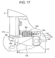
- Fig. 17 is a partially cutaway side view showing a safety device according to Embodiment 10 of the present invention.
- a safety device 175 has the wedge 34, an actuator portion 176 connected to a lower portion of the wedge 34, and the guide portion 36 arranged above the wedge 34 and fixed to the car 3.
- the actuator portion 176 has the actuating mechanism 159 constructed in the same manner as that of Embodiment 9, and a link member 177 displaceable through displacement of the movable portion 162 of the actuating mechanism 159.
- the actuating mechanism 159 is fixed to a lower portion of the car 3 so as to allow reciprocating displacement of the movable portion 162 in the horizontal direction with respect to the car 3.
- the link member 177 is pivotably provided to a stationary shaft 180 fixed to a lower portion of the car 3.
- the stationary shaft 180 is arranged below the actuating mechanism 159.
- the link member 177 has a first link portion 178 and a second link portion 179 which extend in different directions from the stationary shaft 180 taken as the start point.
- the overall configuration of the link member 177 is substantially a prone shape. That is, the second link portion 179 is fixed to the first link portion 178, and the first link portion 178 and the second link portion 179 are integrally pivotable about the stationary shaft 180.
- the length of the first link portion 178 is larger than that of the second link portion 179. Further, an elongate hole 182 is provided at the distal end portion of the first link portion 178. A slide pin 183, which is slidably passed through the elongate hole 182, is fixed to a lower portion of the wedge 34. That is, the wedge 34 is slidably connected to the distal end portion of the first link portion 178. The distal end portion of the movable portion 162 is pivotably connected to the distal end portion of the second link portion 179 through the intermediation of a connecting pin 181.
- the link member 177 is capable of reciprocating movement between a separated position where it keeps the wedge 34 separated away from and below the guide portion 36 and an actuating position where it causes the wedge 34 to wedge in between the car guide rail and the guide portion 36.
- the movable portion 162 is projected from the drive portion 163 when the link member 177 is at the separated position, and it is retracted into the drive portion 163 when the link member is at the actuating position.
- an actuation signal is output from the output portion 32 to each safety device 175, causing the movable portion 162 to advance.
- the link member 177 is pivoted about the stationary shaft 180 for displacement into the actuating position. This causes the wedge 34 to come into contact with the guide portion 36 and the car guide rail, wedging in between the guide portion 36 and the car guide rail. Braking is thus applied to the car 3.
- a recovery signal is transmitted from the output portion 32 to each safety device 175, causing the movable portion 162 to be urged in the retracting direction.
- the car 3 is raised in this state, thus releasing the wedging of the wedge 34 in between the guide portion 36 and the car guide rail.
- the above-described elevator apparatus also provides the same effects as those of Embodiment 2.
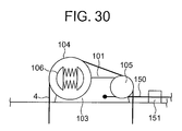
- Fig. 18 is a schematic diagram showing an elevator apparatus according to Embodiment 11 of the present invention.
- a hoisting machine 101 serving as a driving device and a control panel 102 are provided in an upper portion within the hoistway 1.
- the control panel 102 is electrically connected to the hoisting machine 101 and controls the operation of the elevator.
- the hoisting machine 101 has a driving device main body 103 including a motor and a driving sheave 104 rotated by the driving device main body 103.
- a plurality of main ropes 4 are wrapped around the sheave 104.
- the hoisting machine 101 further includes a deflector sheave 105 around which each main rope 4 is wrapped, and a hoisting machine braking device (deceleration braking device) 106 for braking the rotation of the drive sheave 104 to decelerate the car 3.
- the car 3 and a counter weight 107 are suspended in the hoistway 1 by means of the main ropes 4.
- the car 3 and the counterweight 107 are raised and lowered in the hoistway 1 by driving the hoisting machine 101.
- the safety device 33, the hoisting machine braking device 106, and the control panel 102 are electrically connected to a monitor device 108 that constantly monitors the state of the elevator.
- a car position sensor 109, a car speed sensor 110, and a car acceleration sensor 111 are also electrically connected to the monitor device 108.
- the car position sensor 109, the car speed sensor 110, and the car acceleration sensor 111 respectively serve as a car position detecting portion for detecting the speed of the car 3, a car speed detecting portion for detecting the speed of the car 3, and a car acceleration detecting portion for detecting the acceleration of the car 3.
- the car position sensor 109, the car speed sensor 110, and the car acceleration sensor 111 are provided in the hoistway 1.
- Detection means 112 for detecting the state of the elevator includes the car position sensor 109, the car speed sensor 110, and the car acceleration sensor 111. Any of the following may be used for the car position sensor 109: an encoder that detects the position of the car 3 by measuring the amount of rotation of a rotary member that rotates as the car 3 moves; a linear encoder that detects the position of the car 3 by measuring the amount of linear displacement of the car 3; an optical displacement measuring device which includes, for example, a projector and a photodetector provided in the hoistway 1 and a reflection plate provided in the car 3, and which detects the position of the car 3 by measuring how long it takes for light projected from the projector to reach the photodetector.
- the monitor device 108 includes a memory portion 113 and an output portion (calculation portion) 114.
- the memory portion 113 stores in advance a variety of (in this embodiment, two) abnormality determination criteria (set data) serving as criteria for judging whether or not there is an abnormality in the elevator.
- the output portion 114 detects whether or not there is an abnormality in the elevator based on information from the detection means 112 and the memory portion 113.
- the two kinds of abnormality determination criteria stored in the memory portion 113 in this embodiment are car speed abnormality determination criteria relating to the speed of the car 3 and car acceleration abnormality determination criteria relating to the acceleration of the car 3.
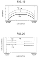
- Fig. 19 is a graph showing the car speed abnormality determination criteria stored in the memory portion 113 of Fig. 18.
- an ascending/descending section of the car 3 in the hoistway 1 includes acceleration/deceleration sections and a constant speed section located between the acceleration/deceleration sections.
- the car 3 accelerates/decelerates in the acceleration/deceleration sections respectively located in the vicinity of the one terminal floor and the other terminal floor.
- the car 3 travels at a constant speed in the constant speed section.
- the car speed abnormality determination criteria has three detection patterns each associated with the position of the car 3. That is, a normal speed detection pattern (normal level) 115 that is the speed of the car 3 during normal operation, a first abnormal speed detection pattern (first abnormal level) 116 having a larger value than the normal speed detection pattern 115, and a second abnormal speed detection pattern (second abnormal level) 117 having a larger value than the first abnormal speed detection pattern 116 are set, each in association with the position of the car 3.
- the normal speed detection pattern 115, the first abnormal speed detection pattern 116, and a second abnormal speed detection pattern 117 are set so as to have a constant value in the constant speed section, and to have a value continuously becoming smaller toward the terminal floor in each of the acceleration and deceleration sections.
- the difference in value between the first abnormal speed detection pattern 116 and the normal speed detection pattern 115, and the difference in value between the second abnormal speed detection pattern 117 and the first abnormal speed detection pattern 116, are set to be substantially constant at all locations in the ascending/descending section.
- Fig. 20 is a graph showing the car acceleration abnormality determination criteria stored in the memory portion 113 of Fig. 18.
- the car acceleration abnormality determination criteria has three detection patterns each associated with the position of the car 3. That is, a normal acceleration detection pattern (normal level) 118 that is the acceleration of the car 3 during normal operation, a first abnormal acceleration detection pattern (first abnormal level) 119 having a larger value than the normal acceleration detection pattern 118, and a second abnormal acceleration detection pattern (second abnormal level) 120 having a larger value than the first abnormal acceleration detection pattern 119 are set, each in association with the position of the car 3.
- the normal acceleration detection pattern 118, the first abnormal acceleration detection pattern 119, and the second abnormal acceleration detection pattern 120 are each set so as to have a value of zero in the constant speed section, a positive value in one of the acceleration/deceleration section, and a negative value in the other acceleration/deceleration section.
- the difference in value between the first abnormal acceleration detection pattern 119 and the normal acceleration detection pattern 118, and the difference in value between the second abnormal acceleration detection pattern 120 and the first abnormal acceleration detection pattern 119 are set to be substantially constant at all locations in the ascending/descending section.
- the memory portion 113 stores the normal speed detection pattern 115, the first abnormal speed detection pattern 116, and the second abnormal speed detection pattern 117 as the car speed abnormality determination criteria, and stores the normal acceleration detection pattern 118, the first abnormal acceleration detection pattern 119, and the second abnormal acceleration detection pattern 120 as the car acceleration abnormality determination criteria.
- the safety device 33, the control panel 102, the hoisting machine braking device 106, the detection means 112, and the memory portion 113 are electrically connected to the output portion 114. Further, a position detection signal, a speed detection signal, and an acceleration detection signal are input to the output portion 114 continuously over time from the car position sensor 109, the car speed sensor 110, and the car acceleration sensor 111.
- the output portion 114 calculates the position of the car 3 based on the input position detection signal.
- the output portion 114 also calculates the speed of the car 3 and the acceleration of the car 3 based on the input speed detection signal and the input acceleration detection signal, respectively, as a variety of (in this example, two) abnormality determination factors.
- the output portion 114 outputs an actuation signal (trigger signal) to the hoisting machine braking device 106 when the speed of the car 3 exceeds the first abnormal speed detection pattern 116, or when the acceleration of the car 3 exceeds the first abnormal acceleration detection pattern 119. At the same time, the output portion 114 outputs a stop signal to the control panel 102 to stop the drive of the hoisting machine 101.
- the output portion 114 When the speed of the car 3 exceeds the second abnormal speed detection pattern 117, or when the acceleration of the car 3 exceeds the second abnormal acceleration detection pattern 120, the output portion 114 outputs an actuation signal to the hoisting machine braking device 106 and the safety device 33. That is, the output portion 114 determines to which braking means it should output the actuation signals according to the degree of the abnormality in the speed and the acceleration of the car 3.
- this embodiment is of the same construction as Embodiment 2.
- the output portion 114 calculates the position, the speed, and the acceleration of the car 3 based on the respective detection signals thus input. After that, the output portion 114 compares the car speed abnormality determination criteria and the car acceleration abnormality determination criteria obtained from the memory portion 113 with the speed and the acceleration of the car 3 calculated based on the respective detection signals input. Through this comparison, the output portion 114 detects whether or not there is an abnormality in either the speed or the acceleration of the car 3.
- the speed of the car 3 has approximately the same value as the normal speed detection pattern, and the acceleration of the car 3 has approximately the same value as the normal acceleration detection pattern.
- the output portion 114 detects that there is no abnormality in either the speed or the acceleration of the car 3, and normal operation of the elevator continues.
- the output portion 114 detects that there is an abnormality in the speed of the car 3. Then, the output portion 114 outputs an actuation signal and a stop signal to the hoisting machine braking device 106 and the control panel 102, respectively. As a result, the hoisting machine 101 is stopped, and the hoisting machine braking device 106 is operated to brake the rotation of the drive sheave 104.
- the output portion 114 When the acceleration of the car 3 abnormally increases and exceeds the first abnormal acceleration set value 119, the output portion 114 outputs an actuation signal and a stop signal to the hoisting machine braking device 106 and the control panel 102, respectively, thereby braking the rotation of the drive sheave 104.
- the output portion 114 outputs an actuation signal to the safety device 33 while still outputting the actuation signal to the hoisting machine braking device 106.
- the safety device 33 is actuated and the car 3 is braked through the same operation as that of Embodiment 2.
- the output portion 114 outputs an actuation signal to the safety device 33 while still outputting the actuation signal to the hoisting machine braking device 106.
- the safety device 33 is actuated.
- the monitor device 108 obtains the speed of the car 3 and the acceleration of the car 3 based on the information from the detection means 112 for detecting the state of the elevator.
- the monitor device 108 judges that there is an abnormality in the obtained speed of the car 3 or the obtained acceleration of the car 3
- the monitor device 108 outputs an actuation signal to at least one of the hoisting machine braking device 106 and the safety device 33. That is, judgment of the presence or absence of an abnormality is made by the monitor device 108 separately for a variety of abnormality determination factors such as the speed of the car and the acceleration of the car. Accordingly, an abnormality in the elevator can be detected earlier and more reliably. Therefore, it takes a shorter time for the braking force on the car 3 to be generated after occurrence of an abnormality in the elevator.
- the monitor device 108 includes the memory portion 113 that stores the car speed abnormality determination criteria used for judging whether or not there is an abnormality in the speed of the car 3, and the car acceleration abnormality determination criteria used for judging whether or not there is an abnormality in the acceleration of the car 3. Therefore, it is easy to change the judgment criteria used for judging whether or not there is an abnormality in the speed and the acceleration of the car 3, respectively, allowing easy adaptation to design changes or the like of the elevator.
- the following patterns are set for the car speed abnormality determination criteria: the normal speed detection pattern 115, the first abnormal speed detection pattern 116 having a larger value than the normal speed detection pattern 115, and the second abnormal speed detection pattern 117 having a larger value than the first abnormal speed detection pattern 116.
- the monitor device 108 When the speed of the car 3 exceeds the first abnormal speed detection pattern 116, the monitor device 108 outputs an actuation signal to the hoisting machine braking device 106,and when the speed of the car 3 exceeds the second abnormal speed detection pattern 117, the monitor device 108 outputs an actuation signal to the hoisting machine braking device 106 and the safety device 33. Therefore, the car 3 can be braked stepwise according to the degree of this abnormality in the speed of the car 3. As a result, the frequency of large shocks exerted on the car 3 can be reduced, and the car 3 can be more reliably stopped.
- the following patterns are set for the car acceleration abnormality determination criteria: the normal acceleration detection pattern 118, the first abnormal acceleration detection pattern 119 having a larger value than the normal acceleration detection pattern 118, and the second abnormal acceleration detection pattern 120 having a larger value than the first abnormal acceleration detection pattern 119.
- the monitor device 108 When the acceleration of the car 3 exceeds the first abnormal acceleration detection pattern 119, the monitor device 108 outputs an actuation signal to the hoisting machine braking device 106,and when the acceleration of the car 3 exceeds the second abnormal acceleration detection pattern 120, the monitor device 108 outputs an actuation signal to the hoisting machine braking device 106 and the safety device 33. Therefore, the car 3 can be braked stepwise according to the degree of an abnormality in the acceleration of the car 3. Normally, an abnormality occurs in the acceleration of the car 3 before an abnormality occurs in the speed of the car 3. As a result, the frequency of large shocks exerted on the car 3 can be reduced, and the car 3 can be more reliably stopped.
- the normal speed detection pattern 115, the first abnormal speed detection pattern 116, and the second abnormal speed detection pattern 117 are each set in association with the position of the car 3. Therefore, the first abnormal speed detection pattern 116 and the second abnormal speed detection pattern 117 each can be set in association with the normal speed detection pattern 115 at all locations in the ascending/descending section of the car 3. In the acceleration/deceleration sections, in particular, the first abnormal speed detection pattern 116 and the second abnormal speed detection pattern 117 each can be set to a relatively small value because the normal speed detection pattern 115 has a small value. As a result, the impact acting on the car 3 upon braking can be mitigated.
- the car speed sensor 110 is used when the monitor 108 obtains the speed of the car 3.
- the speed of the car 3 may be obtained from the position of the car 3 detected by the car position sensor 109. That is, the speed of the car 3 may be obtained by differentiating the position of the car 3 calculated by using the position detection signal from the car position sensor 109.
- the car acceleration sensor 111 is used when the monitor 108 obtains the acceleration of the car 3.
- the acceleration of the car 3 may be obtained from the position of the car 3 detected by the car position sensor 109. That is, the acceleration of the car 3 may be obtained by differentiating, twice, the position of the car 3 calculated by using the position detection signal from the car position sensor 109.
- the output portion 114 determines to which braking means it should output the actuation signals according to the degree of the abnormality in the speed and acceleration of the car 3 constituting the abnormality determination factors.
- the braking means to which the actuation signals are to be output may be determined in advance for each abnormality determination factor.
- Fig. 21 is a schematic diagram showing an elevator apparatus according to Embodiment 12 of the present invention.
- a plurality of hall call buttons 125 are provided in the hall of each floor.
- a plurality of destination floor buttons 126 are provided in the car 3.
- a monitor device 127 has the output portion 114.
- An abnormality determination criteria generating device 128 for generating a car speed abnormality determination criteria and a car acceleration abnormality determination criteria is electrically connected to the output portion 114.
- the abnormality determination criteria generating device 128 is electrically connected to each hall call button 125 and each destination floor button 126.
- a position detection signal is input to the abnormality determination criteria generating device 128 from the car position sensor 109 via the output portion 114.
- the abnormality determination criteria generating device 128 includes a memory portion 129 and a generation portion 130.
- the memory portion 129 stores a plurality of car speed abnormality determination criteria and a plurality of car acceleration abnormality determination criteria, which serve as abnormal judgment criteria for all the cases where the car 3 ascends and descends between the floors.
- the generation portion 130 selects a car speed abnormality determination criteria and a car acceleration abnormality determination criteria one by one from the memory portion 129, and outputs the car speed abnormality determination criteria and the car acceleration abnormality determination criteria to the output portion 114.
- Each car speed abnormality determination criteria has three detection patterns each associated with the position of the car 3, which are similar to those of Fig. 19 of Embodiment 11. Further, each car acceleration abnormality determination criteria has three detection patterns each associated with the position of the car 3, which are similar to those of Fig. 20 of Embodiment 11.
- the generation portion 130 calculates a detection position of the car 3 based on information from the car position sensor 109, and calculates a target floor of the car 3 based on information from at least one of the hall call buttons 125 and the destination floor buttons 126.
- the generation portion 130 selects one by one a car speed abnormality determination criteria and a car acceleration abnormality determination criteria used for a case where the calculated detection position and the target floor are one and the other of the terminal floors.
- this embodiment is of the same construction as Embodiment 11.
- a position detection signal is constantly input to the generation portion 130 from the carposition sensor 109 via the output portion 114.
- the generation portion 130 calculates a detection position and a target floor of the car 3 based on the input position detection signal and the input call signal, and selects one out of both a car speed abnormality determination criteria and a car acceleration abnormality determination criteria. After that, the generation portion 130 outputs the selected car speed abnormality determination criteria and the selected car acceleration abnormality determination criteria to the output portion 114.
- the output portion 114 detects whether or not there is an abnormality in the speed and the acceleration of the car 3 in the same way as in Embodiment 11. Thereafter, this embodiment is of the same operation as Embodiment 9.
- the car speed abnormality determination criteria and the car acceleration abnormality determination criteria are generated based on the information from at least one of the hall call buttons 125 and the destination floor buttons 126. Therefore, it is possible to generate the car speed abnormality determination criteria and the car acceleration abnormality determination criteria corresponding to the target floor. As a result, the time it takes for the braking force on the car 3 to be generated after occurrence of an abnormality in the elevator can be reduced even when a different target floor is selected.
- the generation portion 130 selects one out of both the car speed abnormality determination criteria and car acceleration abnormality determination criteria from among a plurality of car speed abnormality determination criteria and a plurality of car acceleration abnormality determination criteria stored in the memory portion 129.
- the generation portion may directly generate an abnormal speed detection pattern and an abnormal acceleration detection pattern based on the normal speed pattern and the normal acceleration pattern of the car 3 generated by the control panel 102.
- Fig. 22 is a schematic diagram showing an elevator apparatus according to Embodiment 13 of the present invention.
- each of the main ropes 4 is connected to an upper portion of the car 3 via a rope fastening device 131 (Fig. 23).
- the monitor device 108 is mounted on an upper portion of the car 3.
- the car position sensor 109, the car speed sensor 110, and a plurality of rope sensors 132 are electrically connected to the output portion 114.
- Rope sensors 132 are provided in the rope fastening device 131, and each serve as a rope break detecting portion for detecting whether or not a break has occurred in each of the ropes 4.
- the detection means 112 includes the car position sensor 109, the car speed sensor 110, and the rope sensors 132.
- the rope sensors 132 each output a rope brake detection signal to the output portion 114 when the main ropes 4 break.
- the memory portion 113 stores the car speed abnormality determination criteria similar to that of Embodiment 11 shown in Fig. 19, and a rope abnormality determination criteria used as a reference for judging whether or not there is an abnormality in the main ropes 4.
- a first abnormal level indicating a state where at least one of the main ropes 4 have broken, and a second abnormal level indicating a state where all of the main ropes 4 has broken are set for the rope abnormality determination criteria.
- the output portion 114 calculates the position of the car 3 based on the input position detection signal.
- the output portion 114 also calculates the speed of the car 3 and the state of the main ropes 4 based on the input speed detection signal and the input rope brake signal, respectively, as a variety of (in this example, two) abnormality determination factors.
- the output portion 114 outputs an actuation signal (trigger signal) to the hoisting machine braking device 106 when the speed of the car 3 exceeds the first abnormal speed detection pattern 116 (Fig. 19), or when at least one of the main ropes 4 breaks.
- the output portion 114 outputs an actuation signal to the hoisting machine braking device 106 and the safety device 33. That is, the output portion 114 determines to which braking means it should output the actuation signals according to the degree of an abnormality in the speed of the car 3 and the state of the main ropes 4.
- Fig. 23 is a diagram showing the rope fastening device 131 and the rope sensors 132 of Fig. 22.
- Fig. 24 is a diagram showing a state where one of the main ropes 4 of Fig. 23 has broken.
- the rope fastening device 131 includes a plurality of rope connection portions 134 for connecting the main ropes 4 to the car 3.
- the rope connection portions 134 each include an spring 133 provided between the main rope 4 and the car 3. The position of the car 3 is displaceable with respect to the main ropes 4 by the expansion and contraction of the springs 133.
- the rope sensors 132 are each provided to the rope connection portion 134.
- the rope sensors 132 each serve as a displacement measuring device for measuring the amount of expansion of the spring 133.
- Each rope sensor 132 constantly outputs a measurement signal corresponding to the amount of expansion of the spring 133 to the output portion 114.
- a measurement signal obtained when the expansion of the spring 133 returning to its original state has reached a predetermined amount is input to the output portion 114 as a break detection signal.
- each of the rope connection portions 134 may be provided with a scale device that directly measures the tension of the main ropes 4.
- this embodiment is of the same construction as Embodiment 11.
- the output portion 114 calculates the position of the car 3, the speed of the car 3, and the number of main ropes 4 that have broken based on the respective detection signals thus input. After that, the output portion 114 compares the car speed abnormality determination criteria and the rope abnormality determination criteria obtained from the memory portion 113 with the speed of the car 3 and the number of broken main ropes 4 calculated based on the respective detection signals input. Through this comparison, the output portion 114 detects whether or not there is an abnormality in both the speed of the car 3 and the state of the main ropes 4.
- the speed of the car 3 has approximately the same value as the normal speed detection pattern, and the number of broken main ropes 4 is zero.
- the output portion 114 detects that there is no abnormality in either the speed of the car 3 or the state of the main ropes 4, and normal operation of the elevator continues.
- the output portion 114 detects that there is an abnormality in the speed of the car 3. Then, the output portion 114 outputs an actuation signal and a stop signal to the hoisting machine braking device 106 and the control panel 102, respectively. As a result, the hoisting machine 101 is stopped, and the hoisting machine raking device 106 is operated to brake the rotation of the drive sheave 104.
- the output portion 114 outputs an actuation signal and a stop signal to the hoisting machine braking device 106 and the control panel 102, respectively, thereby braking the rotation of the drive sheave 104.
- the output portion 114 outputs an actuation signal to the safety device 33 while still outputting the actuation signal to the hoisting machine braking device 106.
- the safety device 33 is actuated and the car 3 is braked through the same operation as that of Embodiment 2.
- the output portion 114 outputs an actuation signal to the safety device 33 while still outputting the actuation signal to the hoisting machine braking device 106.
- the safety device 33 is actuated.
- the monitor device 108 obtains the speed of the car 3 and the state of the main ropes 4 based on the information from the detection means 112 for detecting the state of the elevator.
- the monitor device 108 judges that there is an abnormality in the obtained speed of the car 3 or the obtained state of the main ropes 4
- the monitor device 108 outputs an actuation signal to at least one of the hoisting machine braking device 106 and the safety device 33.
- the rope sensor 132 is disposed in the rope fastening device 131 provided to the car 3.
- the rope sensor 132 may be disposed in a rope fastening device provided to the counterweight 107.
- the present invention is applied to an elevator apparatus of the type in which the car 3 and the counterweight 107 are suspended in the hoistway 1 by connecting one end portion and the other end portion of the main rope 4 to the car 3 and the counterweight 107, respectively.
- the present invention may also be applied to an elevator apparatus of the type in which the car 3 and the counterweight 107 are suspended in the hoistway 1 by wrapping the main rope 4 around a car suspension sheave and a counterweight suspension sheave, with one end portion and the other end portion of the main rope 4 connected to structures arranged in the hoistway 1.
- the rope sensor is disposed in the rope fastening device provided to the structures arranged in the hoistway 1.
- Fig. 25 is a schematic diagram showing an elevator apparatus according to Embodiment 14 of the present invention.
- a rope sensor 135 serving as a rope brake detecting portion is constituted by lead wires embedded in each of the main ropes 4.
- Each of the lead wires extends in the longitudinal direction of the rope 4. Both end portion of each lead wire are electrically connected to the output portion 114.
- a weak current flows in the lead wires. Cut-off of current flowing in each of the lead wires is input as a rope brake detection signal to the output portion 114.
- this embodiment is of the same construction as Embodiment 13.
- Fig. 26 is a schematic diagram showing an elevator apparatus according to Embodiment 15 of the present invention.
- the car position sensor 109, the car speed sensor 110, and a door sensor 140 are electrically connected to the output portion 114.
- the door sensor 140 serves as an entrance open/closed detecting portion for detecting open/closed of the car entrance 26.
- the detection means 112 includes the car position sensor 109, the car speed sensor 110, and the door sensor 140.
- the door sensor 140 outputs a door-closed detection signal to the output portion 114 when the car entrance 26 is closed.
- the memory portion 113 stores the car speed abnormality determination criteria similar to that of Embodiment 11 shown in Fig. 19, and an entrance abnormality determination criteria used as a reference for judging whether or not there is an abnormality in the open/close state of the car entrance 26. If the car ascends/descends while the car entrance 26 is not closed, the entrance abnormality determination criteria regards this as an abnormal state.
- the output portion 114 calculates the position of the car 3 based on the input position detection signal.
- the output portion 114 also calculates the speed of the car 3 and the state of the car entrance 26 based on the input speed detection signal and the input door-closing detection signal, respectively, as a variety of (in this example, two) abnormality determination factors.
- the output portion 114 outputs an actuation signal to the hoisting machine braking device 104 if the car ascends/descends while the car entrance 26 is not closed, or if the speed of the car 3 exceeds the first abnormal speed detection pattern 116 (Fig. 19). If the speed of the car 3 exceeds the second abnormal speed detection pattern 117 (Fig. 19), the output portion 114 outputs an actuation signal to the hoisting machine braking device 106 and the safety device 33.
- Fig. 27 is a perspective view of the car 3 and the door sensor 140 of Fig. 26.
- Fig. 28 is a perspective view showing a state in which the car entrance 26 of Fig. 27 is open.
- the door sensor 140 is provided at an upper portion of the car entrance 26 and in the center of the car entrance 26 with respect to the width direction of the car 3.
- the door sensor 140 detects displacement of each of the car doors 28 into the door-closed position, and outputs the door-closed detection signal to the output portion 114.
- a contact type sensor detects closing of the doors through its contact with a fixed portion secured to each of the car doors 28.
- the proximity sensor detects closing of the doors without contacting the car doors 28.
- a pair of hall doors 142 for opening/closing a hall entrance 141 are provided at the hall entrance 141.
- the hall doors 142 are engaged to the car doors 28 by means of an engagement device (not shown) when the car 3 rests at a hall floor, and are displaced together with the car doors 28.
- this embodiment is of the same construction as Embodiment 11.
- the output portion 114 calculates the position of the car 3, the speed of the car 3, and the state of the car entrance 26 based on the respective detection signals thus input. After that, the output portion 114 compares the car speed abnormality determination criteria and the drive device state abnormality determination criteria obtained from the memory portion 113 with the speed of the car 3 and the state of the car of the car doors 28 calculated based on the respective detection signals input. Through this comparison, the output portion 114 detects whether or not there is an abnormality in each of the speed of the car 3 and the state of the car entrance 26.
- the speed of the car 3 has approximately the same value as the normal speed detection pattern, and the car entrance 26 is closed while the car 3 ascends/descends.
- the output portion 114 detects that there is no abnormality in each of the speed of the car 3 and the state of the car entrance 26, and normal operation of the elevator continues.
- the output portion 114 detects that there is an abnormality in the speed of the car 3. Then, the output portion 114 outputs an actuation signal and a stop signal to the hoisting machine braking device 106 and the control panel 102, respectively. As a result, the hoisting machine 101 is stopped, and the hoisting machine braking device 106 is actuated to brake the rotation of the drive sheave 104.
- the output portion 114 also detects an abnormality in the car entrance 26 when the car 3 ascends/descends while the car entrance 26 is not closed. Then, the output portion 114 outputs an actuation signal and a stop signal to the hoisting machine braking device 106 and the control panel 102, respectively, thereby braking the rotation of the drive sheave 104.
- the output portion 114 When the speed of the car 3 continues to increase after the actuation of the hoisting machine braking device 106, and exceeds the second abnormal speed set value 117 (Fig. 19), the output portion 114 outputs an actuation signal to the safety device 33 while still outputting the actuation signal to the hoisting machine braking device 106. Thus, the safety device 33 is actuated and the car 3 is braked through the same operation as that of Embodiment 2.
- the monitor device 108 obtains the speed of the car 3 and the state of the car entrance 26 based on the information from the detection means 112 for detecting the state of the elevator.
- the monitor device 108 judges that there is an abnormality in the obtained speed of the car 3 or the obtained state of the car entrance 26, the monitor device 108 outputs an actuation signal to at least one of the hoisting machine braking device 106 and the safety device 33.
- the door sensor 140 only detects the state of the car entrance 26, the door sensor 140 may detect both the state of the car entrance 26 and the state of the elevator hall entrance 141. In this case, the door sensor 140 detects displacement of the elevator hall doors 142 into the door-closed position, as well as displacement of the car doors 28 into the door-closed position. With this construction, abnormality in the elevator can be detected even when only the car doors 28 are displaced due to a problem with the engagement device or the like that engages the car doors 28 and the elevator hall doors 142 with each other.
- Fig. 29 is a schematic diagram showing an elevator apparatus according to Embodiment 16 of the present invention.
- Fig. 30 is a diagram showing an upper portion of the hoistway 1 of Fig. 29.
- a power supply cable 150 is electrically connected to the hoisting machine 101. Drive power is supplied to the hoisting machine 101 via the power supply cable 150 through control of the control panel 102.
- a current sensor 151 serving as a drive device detection portion is provided to the power supply cable 150.
- the current sensor 151 detects the state of the hoisting machine 101 by measuring the current flowing in the power supply cable 150.
- the current sensor 151 outputs to the output portion 114 a current detection signal (drive device state detection signal) corresponding to the value of a current in the power supply cable 150.
- the current sensor 151 is provided in the upper portion of the hoistway 1.
- a current transformer (CT) that measures an induction current generated in accordance with the amount of current flowing in the power supply cable 150 is used as the current sensor 151, for example.
- the car position sensor 109, the car speed sensor 110, and the current sensor 151 are electrically connected to the output portion 114.
- the detectionmeans 112 includes the car position sensor 109, the car speed sensor 110, and the current sensor 151.
- the memory portion 113 stores the car speed abnormality determination criteria similar to that of Embodiment 11 shown in Fig. 19, and a drive device abnormality determination criteria used as a reference for determining whether or not there is an abnormality in the state of the hoisting machine 101.
- the drive device abnormality determination criteria has three detection patterns. That is, a normal level that is the current value flowing in the power supply cable 150 during normal operation, a first abnormal level having a larger value than the normal level, and a second abnormal level having a larger value than the first abnormal level, are set for the drive device abnormality determination criteria.
- the output portion 114 calculates the position of the car 3 based on the input position detection signal.
- the output portion 114 also calculates the speed of the car 3 and the state of the hoisting device 101 based on the input speed detection signal and the input current detection signal, respectively, as a variety of (in this example, two) abnormality determination factors.
- the output portion 114 outputs an actuation signal (trigger signal) to the hoisting machine braking device 106 when the speed of the car 3 exceeds the first abnormal speed detection pattern 116 (Fig. 19), or when the amount of the current flowing in the power supply cable 150 exceeds the value of the first abnormal level of the drive device abnormality determination criteria.
- the output portion 114 outputs an actuation signal to the hoisting machine braking device 106 and the safety device 33. That is, the output portion 114 determines to which braking means it should output the actuation signals according to the degree of abnormality in each of the speed of the car 3 and the state of the hoisting machine 101.
- the output portion 114 calculates the position of the car 3, the speed of the car 3, and the amount of current flowing in the power supply cable 151 based on the respective detection signals thus input. After that, the output portion 114 compares the car speed abnormality determination criteria and the drive device state abnormality determination criteria obtained from the memory portion 113 with the speed of the car 3 and the amount of the current flowing into the current supply cable 150 calculated based on the respective detection signals input. Through this comparison, the output portion 114 detects whether or not there is an abnormality in each of the speed of the car 3 and the state of the hoisting machine 101.
- the speed of the car 3 has approximately the same value as the normal speed detection pattern 115 (Fig. 19), and the amount of current flowing in the power supply cable 150 is at the normal level.
- the output portion 114 detects that there is no abnormality in each of the speed of the car 3 and the state of the hoisting machine 101, and normal operation of the elevator continues.
- the output portion 114 detects that there is an abnormality in the speed of the car 3. Then, the output portion 114 outputs an actuation signal and a stop signal to the hoisting machine braking device 106 and the control panel 102, respectively. As a result, the hoisting machine 101 is stopped, and the hoisting machine braking device 106 is actuated to brake the rotation of the drive sheave 104.
- the output portion 114 outputs an actuation signal and a stop signal to the hoisting machine braking device 106 and the control panel 102, respectively, thereby braking the rotation of the drive sheave 104.
- the output portion 114 When the speed of the car 3 continues to increase after the actuation of the hoisting machine braking device 106, and exceeds the second abnormal speed set value 117 (Fig. 19), the output portion 114 outputs an actuation signal to the safety device 33 while still outputting the actuation signal to the hoisting machine braking device 106. Thus, the safety device 33 is actuated and the car 3 is braked through the same operation as that of Embodiment 2.
- the output portion 114 When the amount of current flowing in the power supply cable 150 exceeds the second abnormal level of the drive device state abnormality determination criteria after the actuation of the hoisting machine braking device 106, the output portion 114 outputs an actuation signal to the safety device 33 while still outputting the actuation signal to the hoisting machine braking device 106. Thus, the safety device 33 is actuated.
- the monitor device 108 obtains the speed of the car 3 and the state of the hoisting machine 101 based on the information from the detection means 112 for detecting the state of the elevator.
- the monitor device 108 judges that there is an abnormality in the obtained speed of the car 3 or the state of the hoisting machine 101
- the monitor device 108 outputs an actuation signal to at least one of the hoisting machine braking device 106 and the safety device 33. This means that the number of targets for abnormality detection increases, and it takes a shorter time for the braking force on the car 3 to be generated after occurrence of an abnormality in the elevator.
- the state of the hoisting machine 101 is detected using the current sensor 151 for measuring the amount of the current flowing in the power supply cable 150.
- the state of the hoisting machine 101 may be detected using a temperature sensor for measuring the temperature of the hoisting machine 101.
- the output portion 114 outputs an actuation signal to the hoisting machine braking device 106 before outputting an actuation signal to the safety device 33.
- the output portion 114 may instead output an actuation signal to one of the following brakes: a car brake for braking the car 3 by gripping the car guide rail 2, which is mounted on the car 3 independently of the safety device 33; a counterweight brake mounted on the counterweight 107 for braking the counterweight 107 by gripping a counterweight guide rail for guiding the counterweight 107; and a rope brake mounted in the hoistway 1 for braking the main ropes 4 by locking up the main ropes 4.
- the electric cable is used as the transmitting means for supplying power from the output portion to the safety device.
- a wireless communication device having a transmitter provided at the output portion and a receiver provided at the safety device may be used instead.
- an optical fiber cable that transmits an optical signal may be used.
- the safety device applies braking with respect to overspeed (motion) of the car in the downward direction.
- the safety device may apply braking with respect to overspeed (motion) of the car in the upward direction by using the safety device fixed upside down to the car.
Landscapes
- Engineering & Computer Science (AREA)
- Mechanical Engineering (AREA)
- Maintenance And Inspection Apparatuses For Elevators (AREA)
Priority Applications (2)
| Application Number | Priority Date | Filing Date | Title |
|---|---|---|---|
| EP12180048A EP2522615A1 (fr) | 2003-03-18 | 2004-03-17 | Appareil d'ascenseur et dispositif de sécurité pour un ascenseur |
| EP12180047A EP2522614A1 (fr) | 2003-03-18 | 2004-03-17 | Appareil d'ascenseur et dispositif de sécurité pour un ascenseur |
Applications Claiming Priority (3)
| Application Number | Priority Date | Filing Date | Title |
|---|---|---|---|
| WOPCT/JP03/03263 | 2003-03-18 | ||
| PCT/JP2003/003263 WO2004083090A1 (fr) | 2003-03-18 | 2003-03-18 | Dispositif d'arret d'urgence pour ascenseur |
| PCT/JP2004/003557 WO2004083091A1 (fr) | 2003-03-18 | 2004-03-17 | Dispositif d'ascenseur et dispositif d'arret d'urgence pour ascenseur |
Related Child Applications (2)
| Application Number | Title | Priority Date | Filing Date |
|---|---|---|---|
| EP12180047A Division-Into EP2522614A1 (fr) | 2003-03-18 | 2004-03-17 | Appareil d'ascenseur et dispositif de sécurité pour un ascenseur |
| EP12180048A Division-Into EP2522615A1 (fr) | 2003-03-18 | 2004-03-17 | Appareil d'ascenseur et dispositif de sécurité pour un ascenseur |
Publications (3)
| Publication Number | Publication Date |
|---|---|
| EP1604935A1 true EP1604935A1 (fr) | 2005-12-14 |
| EP1604935A4 EP1604935A4 (fr) | 2011-07-13 |
| EP1604935B1 EP1604935B1 (fr) | 2016-11-30 |
Family
ID=33018144
Family Applications (3)
| Application Number | Title | Priority Date | Filing Date |
|---|---|---|---|
| EP04721325.1A Expired - Fee Related EP1604935B1 (fr) | 2003-03-18 | 2004-03-17 | Dispositif d'ascenseur et dispositif d'arret d'urgence pour ascenseur |
| EP12180048A Withdrawn EP2522615A1 (fr) | 2003-03-18 | 2004-03-17 | Appareil d'ascenseur et dispositif de sécurité pour un ascenseur |
| EP12180047A Withdrawn EP2522614A1 (fr) | 2003-03-18 | 2004-03-17 | Appareil d'ascenseur et dispositif de sécurité pour un ascenseur |
Family Applications After (2)
| Application Number | Title | Priority Date | Filing Date |
|---|---|---|---|
| EP12180048A Withdrawn EP2522615A1 (fr) | 2003-03-18 | 2004-03-17 | Appareil d'ascenseur et dispositif de sécurité pour un ascenseur |
| EP12180047A Withdrawn EP2522614A1 (fr) | 2003-03-18 | 2004-03-17 | Appareil d'ascenseur et dispositif de sécurité pour un ascenseur |
Country Status (5)
| Country | Link |
|---|---|
| EP (3) | EP1604935B1 (fr) |
| JP (1) | JP4607011B2 (fr) |
| KR (1) | KR100752886B1 (fr) |
| CN (3) | CN101229893B (fr) |
| WO (2) | WO2004083090A1 (fr) |
Cited By (13)
| Publication number | Priority date | Publication date | Assignee | Title |
|---|---|---|---|---|
| WO2008057116A1 (fr) * | 2006-11-08 | 2008-05-15 | Otis Elevator Company | Dispositif de freinage d'un ascenseur |
| EP2107029A1 (fr) * | 2007-01-23 | 2009-10-07 | Mitsubishi Electric Corporation | Appareil ascenseur |
| EP2389333A1 (fr) * | 2009-02-25 | 2011-11-30 | Otis Elevator Company | Dispositif de sécurité d'ascenseur |
| CN101605713B (zh) * | 2007-02-15 | 2011-12-07 | 三菱电机株式会社 | 电梯的安全装置 |
| EP2636626A1 (fr) * | 2010-11-01 | 2013-09-11 | Mitsubishi Electric Corporation | Dispositif d'ascenseur |
| EP2695841A4 (fr) * | 2011-04-01 | 2014-11-19 | Mitsubishi Electric Corp | Dispositif d'ascenseur |
| US8939262B2 (en) | 2009-03-16 | 2015-01-27 | Otis Elevator Company | Elevator over-acceleration and over-speed protection system |
| BE1022834B1 (fr) * | 2015-03-16 | 2016-09-16 | Remote Quality Monitoring S.P.R.L. | Procédé pour collecter des données concernant le fonctionnement d'un ascenseur |
| EP1972593A4 (fr) * | 2006-01-10 | 2017-10-04 | Mitsubishi Denki Kabushiki Kaisha | Ascenseur |
| EP3403976A1 (fr) * | 2017-05-12 | 2018-11-21 | Otis Elevator Company | Cabine d'ascenseur simultanée et actionnement de sécurité de contrepoids |
| CN110817643A (zh) * | 2018-08-10 | 2020-02-21 | 奥的斯电梯公司 | 电梯电气安全致动器控制器 |
| US11261055B2 (en) | 2017-09-15 | 2022-03-01 | Otis Elevator Company | Elevator emergency stop systems |
| EP2920100B1 (fr) * | 2012-11-15 | 2024-01-10 | Otis Elevator Company | Frein d'ascenseur |
Families Citing this family (42)
| Publication number | Priority date | Publication date | Assignee | Title |
|---|---|---|---|---|
| ES2357573T3 (es) * | 2003-10-07 | 2011-04-27 | Otis Elevator Company | Dispositivo de parada de emergencia sin cables que se puede reiniciar de forma remota para un ascensor. |
| CN1886320B (zh) * | 2004-11-16 | 2010-07-21 | 三菱电机株式会社 | 电梯的安全装置 |
| JP4520319B2 (ja) * | 2005-01-26 | 2010-08-04 | 三菱電機株式会社 | レール把持機構ならびにそれを用いたエレベータの安全装置 |
| JP4917030B2 (ja) | 2005-04-13 | 2012-04-18 | 三菱電機株式会社 | エレベータ装置 |
| JP4403123B2 (ja) * | 2005-09-21 | 2010-01-20 | 三菱電機株式会社 | エレベータ装置 |
| JP5179756B2 (ja) * | 2005-11-21 | 2013-04-10 | 三菱電機株式会社 | エレベータのブレーキシステム |
| JP5037139B2 (ja) | 2006-02-01 | 2012-09-26 | 三菱電機株式会社 | エレベータ装置 |
| JP4700646B2 (ja) * | 2007-03-26 | 2011-06-15 | 株式会社神戸製鋼所 | ワーク位置決め装置の制御装置およびそのプログラム |
| KR100903469B1 (ko) | 2007-05-21 | 2009-06-18 | 미쓰비시덴키 가부시키가이샤 | 엘리베이터 장치 |
| KR100902452B1 (ko) | 2007-06-19 | 2009-06-11 | 미쓰비시덴키 가부시키가이샤 | 엘리베이터 장치 |
| JP4812037B2 (ja) * | 2007-07-23 | 2011-11-09 | 株式会社日立製作所 | エレベーター乗りかごの速度検出装置およびエレベーターの安全装置 |
| JP5355367B2 (ja) * | 2009-12-07 | 2013-11-27 | 株式会社日立製作所 | ダブルデッキエレベータ及びダブルデッキエレベータの制御方法 |
| JP2011121742A (ja) * | 2009-12-11 | 2011-06-23 | Mitsubishi Electric Corp | エレベーターの制動装置 |
| CN101792089A (zh) * | 2010-03-23 | 2010-08-04 | 上海能港电气工程科技有限公司 | 起重机失控保护开关装置及相关控制方法 |
| KR101382027B1 (ko) * | 2010-04-22 | 2014-04-04 | 미쓰비시덴키 가부시키가이샤 | 엘리베이터의 비상정지장치 |
| CN104860148B (zh) * | 2010-06-18 | 2017-07-21 | 株式会社日立制作所 | 电梯系统 |
| CN102009886B (zh) * | 2010-09-16 | 2012-12-26 | 广州市特种机电设备检测研究院 | 电梯非正常停机故障自动识别方法及装置 |
| DE102011076241A1 (de) * | 2011-03-07 | 2012-09-13 | Dekra Industrial Gmbh | Verfahren und Vorrichtung zur Prüfung der ordnungsgemäßen Funktionsfähigkeit eines Aufzugs |
| KR101470271B1 (ko) * | 2011-03-24 | 2014-12-05 | 미쓰비시덴키 가부시키가이샤 | 더블-데크 엘리베이터 |
| CN103648952B (zh) * | 2011-07-08 | 2016-01-20 | 株式会社日立制作所 | 电梯用调速器装置 |
| CN104428232B (zh) * | 2012-07-05 | 2017-02-22 | 三菱电机株式会社 | 电梯装置 |
| CN102765644A (zh) * | 2012-07-18 | 2012-11-07 | 江南大学 | 分布式电梯加速度故障诊断系统 |
| CN103010875B (zh) * | 2012-12-19 | 2014-07-02 | 上海电机学院 | 电梯控制系统及电梯控制方法 |
| KR101425843B1 (ko) * | 2013-03-06 | 2014-08-11 | 숭실대학교산학협력단 | 엘리베이터용 비상 제동 장치 및 그 제어방법 |
| JP2014181123A (ja) * | 2013-03-21 | 2014-09-29 | Hitachi Ltd | エレベータ装置 |
| KR101488412B1 (ko) * | 2014-07-09 | 2015-01-30 | (주)미주하이텍 | 승강기용 독립 제동 장치 |
| CN104150316B (zh) * | 2014-08-07 | 2017-05-24 | 江苏蒙哥马利电梯有限公司 | 一种防止电梯轿厢异常移动的装置 |
| CN105173981A (zh) * | 2015-08-28 | 2015-12-23 | 中菱电梯有限公司 | 一种安全可靠的曳引式乘客电梯及其安全控制方法 |
| JP6062009B2 (ja) * | 2015-09-18 | 2017-01-18 | 三菱電機株式会社 | エレベータ装置 |
| WO2017161492A1 (fr) * | 2016-03-22 | 2017-09-28 | 黄志斌 | Système de protection indépendant contre les accidents d'ascenseur et procédé de protection |
| CN105836566A (zh) * | 2016-05-12 | 2016-08-10 | 苏州富士电梯有限公司 | 一种电梯轿厢紧急保护装置 |
| JP6636411B2 (ja) * | 2016-11-18 | 2020-01-29 | 株式会社日立製作所 | エレベーター制御装置及びエレベーター制御方法 |
| CN106586749A (zh) * | 2016-12-27 | 2017-04-26 | 南通理工学院 | 应用于升降机的智能监测系统 |
| CN109775508B (zh) * | 2017-11-10 | 2020-07-14 | 上海三菱电梯有限公司 | 紧急制动装置及具有该紧急制动装置的电梯系统 |
| CN110361208A (zh) * | 2018-03-26 | 2019-10-22 | 上海三菱电梯有限公司 | 电梯轿厢紧急制动装置的试验方法及用于该方法的装置 |
| WO2019244245A1 (fr) * | 2018-06-19 | 2019-12-26 | 三菱電機ビルテクノサービス株式会社 | Dispositif d'identification de transition de température, système de planification de maintenance, et système d'ascenseur |
| CN108639892B (zh) * | 2018-07-25 | 2020-07-10 | 厦门乃尔电子有限公司 | 一种电梯轿厢速度检测系统及方法 |
| US20210101777A1 (en) * | 2019-10-03 | 2021-04-08 | Otis Elevator Company | Elevator brake control |
| JP7078145B1 (ja) * | 2021-02-09 | 2022-05-31 | フジテック株式会社 | エレベーター制御装置 |
| CN113003350B (zh) * | 2021-03-29 | 2022-11-25 | 广州广日电梯工业有限公司 | 电梯安全控制方法以及电梯安全控制装置 |
| CN113415689A (zh) * | 2021-06-24 | 2021-09-21 | 北京房地天宇特种设备安装工程有限公司 | 一种电梯控制系统、方法及电梯 |
| TWI823303B (zh) * | 2022-03-23 | 2023-11-21 | 辛耘企業股份有限公司 | 具有防止掉落功能的升降設備與第一制動裝置 |
Citations (3)
| Publication number | Priority date | Publication date | Assignee | Title |
|---|---|---|---|---|
| WO2000037348A1 (fr) * | 1998-12-22 | 2000-06-29 | Otis Elevator Company | Mecanisme regulateur sans cable pour cabine d'ascenseur |
| WO2000039016A1 (fr) * | 1998-12-23 | 2000-07-06 | Otis Elevator Company | Systeme de securite electronique pour ascenseur |
| WO2000058195A1 (fr) * | 1999-03-26 | 2000-10-05 | Otis Elevator Company | Systeme de secours pour ascenseur |
Family Cites Families (19)
| Publication number | Priority date | Publication date | Assignee | Title |
|---|---|---|---|---|
| JPS5446459U (fr) * | 1977-09-07 | 1979-03-30 | ||
| JPS5974875A (ja) * | 1982-10-15 | 1984-04-27 | 三菱電機株式会社 | トラクシヨン式エレベ−タ |
| JPH0674114B2 (ja) * | 1984-11-13 | 1994-09-21 | 株式会社日立製作所 | エレベ−タ−の防犯装置 |
| JP2747071B2 (ja) * | 1989-12-28 | 1998-05-06 | 株式会社日立ビルシステム | 昇降機遠隔監視装置 |
| JPH0466491A (ja) * | 1990-07-09 | 1992-03-02 | Mitsubishi Electric Corp | ロープレスリニアモータエレベーター |
| JP2736176B2 (ja) * | 1991-02-14 | 1998-04-02 | 株式会社東芝 | リニアモータ駆動エレベータの制御装置 |
| JPH04292389A (ja) * | 1991-03-18 | 1992-10-16 | Toyota Motor Corp | 昇降架台の落下防止装置 |
| JP2635257B2 (ja) * | 1991-12-10 | 1997-07-30 | 三菱電機株式会社 | エレベータ制御装置 |
| JP3059006B2 (ja) * | 1992-08-31 | 2000-07-04 | 株式会社東芝 | 縦横自走式エレベーターの運行制御方法及びその装置 |
| JP3090809B2 (ja) * | 1993-03-05 | 2000-09-25 | 株式会社東芝 | 自走式エレベータ |
| JPH06263360A (ja) * | 1993-03-11 | 1994-09-20 | Toshiba Corp | 自走式エレベータの安全装置 |
| US5366045A (en) * | 1993-09-03 | 1994-11-22 | Eaton Corporation | Brake mechanism for a storage and retrieval vehicle |
| ATE256625T1 (de) * | 1995-10-17 | 2004-01-15 | Inventio Ag | Sicherheitseinrichtung bei multimobil- aufzugsgruppen |
| JPH1059648A (ja) * | 1996-08-22 | 1998-03-03 | Toshiba Corp | エレベータのブレーキ |
| JPH11246141A (ja) * | 1998-03-06 | 1999-09-14 | Mitsubishi Electric Corp | エレベーターの終端階減速装置 |
| JP4326618B2 (ja) * | 1999-02-03 | 2009-09-09 | 三菱電機株式会社 | エレベーターの群管理装置 |
| JP4400956B2 (ja) | 1999-09-14 | 2010-01-20 | 東芝エレベータ株式会社 | エレベータの安全装置 |
| JP4553535B2 (ja) * | 2001-09-28 | 2010-09-29 | 三菱電機株式会社 | エレベータ装置 |
| WO2004043841A1 (fr) * | 2002-11-09 | 2004-05-27 | Thyssenkrupp Elevator Ag | Dispositif de securite destine a un systeme d'ascenseur comportant plusieurs cabines dans une cage |
-
2003
- 2003-03-18 WO PCT/JP2003/003263 patent/WO2004083090A1/fr active Application Filing
-
2004
- 2004-03-17 CN CN2008100825742A patent/CN101229893B/zh not_active Expired - Fee Related
- 2004-03-17 EP EP04721325.1A patent/EP1604935B1/fr not_active Expired - Fee Related
- 2004-03-17 CN CN2008100825738A patent/CN101229892B/zh not_active Expired - Fee Related
- 2004-03-17 CN CN2004800011000A patent/CN1701033B/zh not_active Expired - Fee Related
- 2004-03-17 WO PCT/JP2004/003557 patent/WO2004083091A1/fr active Application Filing
- 2004-03-17 EP EP12180048A patent/EP2522615A1/fr not_active Withdrawn
- 2004-03-17 JP JP2005503714A patent/JP4607011B2/ja not_active Expired - Fee Related
- 2004-03-17 EP EP12180047A patent/EP2522614A1/fr not_active Withdrawn
- 2004-03-17 KR KR1020057007777A patent/KR100752886B1/ko active IP Right Grant
Patent Citations (3)
| Publication number | Priority date | Publication date | Assignee | Title |
|---|---|---|---|---|
| WO2000037348A1 (fr) * | 1998-12-22 | 2000-06-29 | Otis Elevator Company | Mecanisme regulateur sans cable pour cabine d'ascenseur |
| WO2000039016A1 (fr) * | 1998-12-23 | 2000-07-06 | Otis Elevator Company | Systeme de securite electronique pour ascenseur |
| WO2000058195A1 (fr) * | 1999-03-26 | 2000-10-05 | Otis Elevator Company | Systeme de secours pour ascenseur |
Non-Patent Citations (1)
| Title |
|---|
| See also references of WO2004083091A1 * |
Cited By (24)
| Publication number | Priority date | Publication date | Assignee | Title |
|---|---|---|---|---|
| EP1972593A4 (fr) * | 2006-01-10 | 2017-10-04 | Mitsubishi Denki Kabushiki Kaisha | Ascenseur |
| CN101535163B (zh) * | 2006-11-08 | 2011-09-28 | 奥蒂斯电梯公司 | 电梯制动装置 |
| WO2008057116A1 (fr) * | 2006-11-08 | 2008-05-15 | Otis Elevator Company | Dispositif de freinage d'un ascenseur |
| US8186483B2 (en) | 2006-11-08 | 2012-05-29 | Otis Elevator Company | Elevator braking device |
| EP2107029A4 (fr) * | 2007-01-23 | 2013-07-31 | Mitsubishi Electric Corp | Appareil ascenseur |
| EP2107029A1 (fr) * | 2007-01-23 | 2009-10-07 | Mitsubishi Electric Corporation | Appareil ascenseur |
| CN101605713B (zh) * | 2007-02-15 | 2011-12-07 | 三菱电机株式会社 | 电梯的安全装置 |
| EP2389333A4 (fr) * | 2009-02-25 | 2012-08-08 | Otis Elevator Co | Dispositif de sécurité d'ascenseur |
| EP2389333A1 (fr) * | 2009-02-25 | 2011-11-30 | Otis Elevator Company | Dispositif de sécurité d'ascenseur |
| US8939262B2 (en) | 2009-03-16 | 2015-01-27 | Otis Elevator Company | Elevator over-acceleration and over-speed protection system |
| EP2636626A1 (fr) * | 2010-11-01 | 2013-09-11 | Mitsubishi Electric Corporation | Dispositif d'ascenseur |
| EP2636626A4 (fr) * | 2010-11-01 | 2014-11-26 | Mitsubishi Electric Corp | Dispositif d'ascenseur |
| US9505587B2 (en) | 2010-11-01 | 2016-11-29 | Mitsubishi Electric Corporation | Elevator with acceleration detection |
| EP2695841A4 (fr) * | 2011-04-01 | 2014-11-19 | Mitsubishi Electric Corp | Dispositif d'ascenseur |
| EP2920100B1 (fr) * | 2012-11-15 | 2024-01-10 | Otis Elevator Company | Frein d'ascenseur |
| BE1022834B1 (fr) * | 2015-03-16 | 2016-09-16 | Remote Quality Monitoring S.P.R.L. | Procédé pour collecter des données concernant le fonctionnement d'un ascenseur |
| EP3070040A3 (fr) * | 2015-03-16 | 2016-12-14 | Remote Quality Monitoring | Procédé pour collecter des données concernant le fonctionnement d'un ascenseur |
| EP3070040A2 (fr) | 2015-03-16 | 2016-09-21 | Remote Quality Monitoring | Procédé pour collecter des données concernant le fonctionnement d'un ascenseur |
| EP3403976A1 (fr) * | 2017-05-12 | 2018-11-21 | Otis Elevator Company | Cabine d'ascenseur simultanée et actionnement de sécurité de contrepoids |
| CN108861965A (zh) * | 2017-05-12 | 2018-11-23 | 奥的斯电梯公司 | 同时进行的电梯轿厢安全装置和配重安全装置致动 |
| US10501286B2 (en) | 2017-05-12 | 2019-12-10 | Otis Elevator Company | Simultaneous elevator car and counterweight safety actuation |
| CN108861965B (zh) * | 2017-05-12 | 2020-11-17 | 奥的斯电梯公司 | 同时进行的电梯轿厢安全装置和配重安全装置致动 |
| US11261055B2 (en) | 2017-09-15 | 2022-03-01 | Otis Elevator Company | Elevator emergency stop systems |
| CN110817643A (zh) * | 2018-08-10 | 2020-02-21 | 奥的斯电梯公司 | 电梯电气安全致动器控制器 |
Also Published As
| Publication number | Publication date |
|---|---|
| EP2522615A1 (fr) | 2012-11-14 |
| JP4607011B2 (ja) | 2011-01-05 |
| CN101229892A (zh) | 2008-07-30 |
| JPWO2004083091A1 (ja) | 2006-06-22 |
| KR100752886B1 (ko) | 2007-08-28 |
| WO2004083091A1 (fr) | 2004-09-30 |
| CN101229892B (zh) | 2011-04-06 |
| EP1604935A4 (fr) | 2011-07-13 |
| WO2004083090A1 (fr) | 2004-09-30 |
| CN1701033B (zh) | 2010-05-12 |
| KR20050072781A (ko) | 2005-07-12 |
| CN101229893B (zh) | 2012-04-04 |
| EP1604935B1 (fr) | 2016-11-30 |
| CN1701033A (zh) | 2005-11-23 |
| EP2522614A1 (fr) | 2012-11-14 |
| CN101229893A (zh) | 2008-07-30 |
Similar Documents
| Publication | Publication Date | Title |
|---|---|---|
| EP1604935A1 (fr) | Dispositif d'ascenseur et dispositif d'arret d'urgence pour ascenseur | |
| EP1741656B2 (fr) | Ascenseur | |
| US7614482B2 (en) | Elevator rope slip detector and elevator system | |
| EP1752407B1 (fr) | Système élévateur | |
| EP2380838B1 (fr) | Dispositif de détection de glissement de câble d'ascenseur et appareil ascenseur | |
| EP1731470B1 (fr) | Dispositif de commande d'ascenseur | |
| EP1749778B1 (fr) | Detecteur de joint de rail d'ascenseur et systeme ascenseur | |
| EP1749777B1 (fr) | Contrôleur d'élévateur | |
| EP1741659B1 (fr) | Appareil élévateur | |
| EP1741657B1 (fr) | Appareil élévateur | |
| US7556127B2 (en) | Elevator control device |
Legal Events
| Date | Code | Title | Description |
|---|---|---|---|
| PUAI | Public reference made under article 153(3) epc to a published international application that has entered the european phase |
Free format text: ORIGINAL CODE: 0009012 |
|
| 17P | Request for examination filed |
Effective date: 20050405 |
|
| AK | Designated contracting states |
Kind code of ref document: A1 Designated state(s): AT BE BG CH CY CZ DE DK EE ES FI FR GB GR HU IE IT LI LU MC NL PL PT RO SE SI SK TR |
|
| AX | Request for extension of the european patent |
Extension state: AL LT LV MK |
|
| RAP1 | Party data changed (applicant data changed or rights of an application transferred) |
Owner name: MITSUBISHI DENKI KABUSHIKI KAISHA |
|
| DAX | Request for extension of the european patent (deleted) | ||
| RBV | Designated contracting states (corrected) |
Designated state(s): DE |
|
| A4 | Supplementary search report drawn up and despatched |
Effective date: 20110616 |
|
| 17Q | First examination report despatched |
Effective date: 20120411 |
|
| REG | Reference to a national code |
Ref country code: DE Ref legal event code: R079 Ref document number: 602004050400 Country of ref document: DE Free format text: PREVIOUS MAIN CLASS: B66B0005060000 Ipc: B66B0005180000 |
|
| GRAP | Despatch of communication of intention to grant a patent |
Free format text: ORIGINAL CODE: EPIDOSNIGR1 |
|
| RIC1 | Information provided on ipc code assigned before grant |
Ipc: B66B 5/06 20060101ALI20160520BHEP Ipc: B66B 5/18 20060101AFI20160520BHEP |
|
| INTG | Intention to grant announced |
Effective date: 20160617 |
|
| GRAS | Grant fee paid |
Free format text: ORIGINAL CODE: EPIDOSNIGR3 |
|
| GRAA | (expected) grant |
Free format text: ORIGINAL CODE: 0009210 |
|
| AK | Designated contracting states |
Kind code of ref document: B1 Designated state(s): DE |
|
| REG | Reference to a national code |
Ref country code: DE Ref legal event code: R096 Ref document number: 602004050400 Country of ref document: DE |
|
| REG | Reference to a national code |
Ref country code: DE Ref legal event code: R097 Ref document number: 602004050400 Country of ref document: DE |
|
| PLBE | No opposition filed within time limit |
Free format text: ORIGINAL CODE: 0009261 |
|
| STAA | Information on the status of an ep patent application or granted ep patent |
Free format text: STATUS: NO OPPOSITION FILED WITHIN TIME LIMIT |
|
| 26N | No opposition filed |
Effective date: 20170831 |
|
| PGFP | Annual fee paid to national office [announced via postgrant information from national office to epo] |
Ref country code: DE Payment date: 20180306 Year of fee payment: 15 |
|
| REG | Reference to a national code |
Ref country code: DE Ref legal event code: R119 Ref document number: 602004050400 Country of ref document: DE |
|
| PG25 | Lapsed in a contracting state [announced via postgrant information from national office to epo] |
Ref country code: DE Free format text: LAPSE BECAUSE OF NON-PAYMENT OF DUE FEES Effective date: 20191001 |