EP1602518A2 - Dispositif d'alimentation de puissance pour porte coulissante - Google Patents
Dispositif d'alimentation de puissance pour porte coulissante Download PDFInfo
- Publication number
- EP1602518A2 EP1602518A2 EP05300368A EP05300368A EP1602518A2 EP 1602518 A2 EP1602518 A2 EP 1602518A2 EP 05300368 A EP05300368 A EP 05300368A EP 05300368 A EP05300368 A EP 05300368A EP 1602518 A2 EP1602518 A2 EP 1602518A2
- Authority
- EP
- European Patent Office
- Prior art keywords
- sliding door
- rotating drum
- flexible tube
- case
- coiled spring
- Prior art date
- Legal status (The legal status is an assumption and is not a legal conclusion. Google has not performed a legal analysis and makes no representation as to the accuracy of the status listed.)
- Withdrawn
Links
Images


Classifications
-
- B—PERFORMING OPERATIONS; TRANSPORTING
- B60—VEHICLES IN GENERAL
- B60R—VEHICLES, VEHICLE FITTINGS, OR VEHICLE PARTS, NOT OTHERWISE PROVIDED FOR
- B60R16/00—Electric or fluid circuits specially adapted for vehicles and not otherwise provided for; Arrangement of elements of electric or fluid circuits specially adapted for vehicles and not otherwise provided for
- B60R16/02—Electric or fluid circuits specially adapted for vehicles and not otherwise provided for; Arrangement of elements of electric or fluid circuits specially adapted for vehicles and not otherwise provided for electric constitutive elements
- B60R16/0207—Wire harnesses
- B60R16/0215—Protecting, fastening and routing means therefor
-
- B—PERFORMING OPERATIONS; TRANSPORTING
- B60—VEHICLES IN GENERAL
- B60R—VEHICLES, VEHICLE FITTINGS, OR VEHICLE PARTS, NOT OTHERWISE PROVIDED FOR
- B60R16/00—Electric or fluid circuits specially adapted for vehicles and not otherwise provided for; Arrangement of elements of electric or fluid circuits specially adapted for vehicles and not otherwise provided for
- B60R16/02—Electric or fluid circuits specially adapted for vehicles and not otherwise provided for; Arrangement of elements of electric or fluid circuits specially adapted for vehicles and not otherwise provided for electric constitutive elements
- B60R16/023—Electric or fluid circuits specially adapted for vehicles and not otherwise provided for; Arrangement of elements of electric or fluid circuits specially adapted for vehicles and not otherwise provided for electric constitutive elements for transmission of signals between vehicle parts or subsystems
- B60R16/027—Electric or fluid circuits specially adapted for vehicles and not otherwise provided for; Arrangement of elements of electric or fluid circuits specially adapted for vehicles and not otherwise provided for electric constitutive elements for transmission of signals between vehicle parts or subsystems between relatively movable parts of the vehicle, e.g. between steering wheel and column
-
- E—FIXED CONSTRUCTIONS
- E05—LOCKS; KEYS; WINDOW OR DOOR FITTINGS; SAFES
- E05D—HINGES OR SUSPENSION DEVICES FOR DOORS, WINDOWS OR WINGS
- E05D11/00—Additional features or accessories of hinges
- E05D11/0081—Additional features or accessories of hinges for transmitting energy, e.g. electrical cable routing
-
- E—FIXED CONSTRUCTIONS
- E05—LOCKS; KEYS; WINDOW OR DOOR FITTINGS; SAFES
- E05F—DEVICES FOR MOVING WINGS INTO OPEN OR CLOSED POSITION; CHECKS FOR WINGS; WING FITTINGS NOT OTHERWISE PROVIDED FOR, CONCERNED WITH THE FUNCTIONING OF THE WING
- E05F15/00—Power-operated mechanisms for wings
- E05F15/60—Power-operated mechanisms for wings using electrical actuators
- E05F15/603—Power-operated mechanisms for wings using electrical actuators using rotary electromotors
- E05F15/632—Power-operated mechanisms for wings using electrical actuators using rotary electromotors for horizontally-sliding wings
-
- F—MECHANICAL ENGINEERING; LIGHTING; HEATING; WEAPONS; BLASTING
- F16—ENGINEERING ELEMENTS AND UNITS; GENERAL MEASURES FOR PRODUCING AND MAINTAINING EFFECTIVE FUNCTIONING OF MACHINES OR INSTALLATIONS; THERMAL INSULATION IN GENERAL
- F16L—PIPES; JOINTS OR FITTINGS FOR PIPES; SUPPORTS FOR PIPES, CABLES OR PROTECTIVE TUBING; MEANS FOR THERMAL INSULATION IN GENERAL
- F16L3/00—Supports for pipes, cables or protective tubing, e.g. hangers, holders, clamps, cleats, clips, brackets
- F16L3/01—Supports for pipes, cables or protective tubing, e.g. hangers, holders, clamps, cleats, clips, brackets for supporting or guiding the pipes, cables or protective tubing, between relatively movable points, e.g. movable channels
- F16L3/015—Supports for pipes, cables or protective tubing, e.g. hangers, holders, clamps, cleats, clips, brackets for supporting or guiding the pipes, cables or protective tubing, between relatively movable points, e.g. movable channels using articulated- or supple-guiding elements
-
- H—ELECTRICITY
- H02—GENERATION; CONVERSION OR DISTRIBUTION OF ELECTRIC POWER
- H02G—INSTALLATION OF ELECTRIC CABLES OR LINES, OR OF COMBINED OPTICAL AND ELECTRIC CABLES OR LINES
- H02G11/00—Arrangements of electric cables or lines between relatively-movable parts
- H02G11/006—Arrangements of electric cables or lines between relatively-movable parts using extensible carrier for the cable, e.g. self-coiling spring
-
- E—FIXED CONSTRUCTIONS
- E05—LOCKS; KEYS; WINDOW OR DOOR FITTINGS; SAFES
- E05F—DEVICES FOR MOVING WINGS INTO OPEN OR CLOSED POSITION; CHECKS FOR WINGS; WING FITTINGS NOT OTHERWISE PROVIDED FOR, CONCERNED WITH THE FUNCTIONING OF THE WING
- E05F15/00—Power-operated mechanisms for wings
- E05F15/40—Safety devices, e.g. detection of obstructions or end positions
- E05F15/42—Detection using safety edges
- E05F15/44—Detection using safety edges responsive to changes in electrical conductivity
- E05F2015/447—Detection using safety edges responsive to changes in electrical conductivity using switches in serial arrangement
-
- E—FIXED CONSTRUCTIONS
- E05—LOCKS; KEYS; WINDOW OR DOOR FITTINGS; SAFES
- E05Y—INDEXING SCHEME RELATING TO HINGES OR OTHER SUSPENSION DEVICES FOR DOORS, WINDOWS OR WINGS AND DEVICES FOR MOVING WINGS INTO OPEN OR CLOSED POSITION, CHECKS FOR WINGS AND WING FITTINGS NOT OTHERWISE PROVIDED FOR, CONCERNED WITH THE FUNCTIONING OF THE WING
- E05Y2400/00—Electronic control; Power supply; Power or signal transmission; User interfaces
- E05Y2400/60—Power supply; Power or signal transmission
- E05Y2400/65—Power or signal transmission
- E05Y2400/654—Power or signal transmission by electrical cables
-
- E—FIXED CONSTRUCTIONS
- E05—LOCKS; KEYS; WINDOW OR DOOR FITTINGS; SAFES
- E05Y—INDEXING SCHEME RELATING TO HINGES OR OTHER SUSPENSION DEVICES FOR DOORS, WINDOWS OR WINGS AND DEVICES FOR MOVING WINGS INTO OPEN OR CLOSED POSITION, CHECKS FOR WINGS AND WING FITTINGS NOT OTHERWISE PROVIDED FOR, CONCERNED WITH THE FUNCTIONING OF THE WING
- E05Y2800/00—Details, accessories and auxiliary operations not otherwise provided for
- E05Y2800/34—Form stability
- E05Y2800/342—Deformable
- E05Y2800/344—Deformable elastically
-
- E—FIXED CONSTRUCTIONS
- E05—LOCKS; KEYS; WINDOW OR DOOR FITTINGS; SAFES
- E05Y—INDEXING SCHEME RELATING TO HINGES OR OTHER SUSPENSION DEVICES FOR DOORS, WINDOWS OR WINGS AND DEVICES FOR MOVING WINGS INTO OPEN OR CLOSED POSITION, CHECKS FOR WINGS AND WING FITTINGS NOT OTHERWISE PROVIDED FOR, CONCERNED WITH THE FUNCTIONING OF THE WING
- E05Y2900/00—Application of doors, windows, wings or fittings thereof
- E05Y2900/50—Application of doors, windows, wings or fittings thereof for vehicles
- E05Y2900/53—Application of doors, windows, wings or fittings thereof for vehicles characterised by the type of wing
- E05Y2900/531—Doors
-
- H—ELECTRICITY
- H02—GENERATION; CONVERSION OR DISTRIBUTION OF ELECTRIC POWER
- H02G—INSTALLATION OF ELECTRIC CABLES OR LINES, OR OF COMBINED OPTICAL AND ELECTRIC CABLES OR LINES
- H02G3/00—Installations of electric cables or lines or protective tubing therefor in or on buildings, equivalent structures or vehicles
- H02G3/02—Details
- H02G3/04—Protective tubing or conduits, e.g. cable ladders or cable troughs
- H02G3/0462—Tubings, i.e. having a closed section
- H02G3/0468—Corrugated
Definitions
- One of the object of the invention is to provide a power supply device for a sliding door enabling to be downsized, in which the flexible tube and wire harness received therein ranging from the vehicle body side to the sliding door is not likely damaged, and the flexible tube is bent and moved in a relatively small space.
- said wire harness comprises one sheet or plurality sheets of flat cable
- said flexible tube comprises a corrugated tube having a cross section of a longer vertical portion than a horizontal portion in which said one sheet or plurality sheets of flat cable are received with the width thereof vertically directed.
- the corrugated tube preferably includes a rib formed running along a longitudinal direction on at least one of an upper surface and lower surface thereof.
- a stopper for restricting a rotation angle of the rotating drum is preferably provided respectively on a lower surface of a bottom portion of the rotating drum, and a corresponding upper surface of a bottom portion of the lower case.
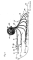
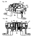
- Figs. 4 to 10 show the construction of the extra-length absorbing unit 14.
- the extra-length absorbing unit 14 includes a case 30 having a gate 28 for the flexible tube 18, a rotating drum 32 for winding the flexible tube 18 in the case 30, and a coiled spring 34 for providing a turning force with the rotating drum 32 in a winding direction of the flexible tube 18.
- the flexible tube comprises a corrugated tube having a cross section of a longer vertical portion than a horizontal portion in which the flat cable is inserted into the flexible tube 18 with the width thereof vertically directed.
- a cut portion 35 is formed in the flexible tube 18 along the longitudinal direction so that the flat cable 20 is easily inserted into the flexible tube.
- the third solution is to provide a slant surface and a through hole in the bottom portion 78 of the lower case 30A for discharging the foreign material entered into the case 30. With the slant surface and the through hole thus provided, the foreign material and water entered into the case 30 can be discharged out of the case.
- the extra-length absorbing unit 14 upon assembling the extra-length absorbing unit 14, it becomes easy to pile the components in order from the bottom to upper by using the sub-cover 48, thus improving the assembling efficiency to provide a power supply device for a sliding door having a more stable quality. Since the power supply device for a sliding door may be operated at the time of finishing the assembling up to the sub-cover 48, it is possible to check the operation in the way of assembling, thus remarkably lowering the possibility of finding the malfunctioning after fitting the upper case.
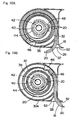
- Fig. 19 shows a preferable embodiment of the rotating drum 32.
- the rotating drum has an opening portion 90 formed on a bottom plate portion thereof at a position corresponding to a portion to which an end portion of the coiled spring 34 is come into contact.
- the opening portion 90 thus formed, at first the coiled spring 34 is installed in the prescribed position of the lower case 30A in such manner that the lower end of the coiled spring 34 is fitted in a spring-end supporting portion of the lower case 30A. Then, the upper end portion 34a of the coiled spring 34 is fitted in the spring-end supporting portion of the rotating drum 32 while viewing the upper end portion 34a of the coiled spring 34 from the opening portion 90 when the rotating drum 32 is assembled.
- the rotating drum 32 may be simply and effectively assembled.
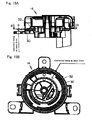
- Fig. 20 shows a preferable embodiment of the assembled rotating drum 32, lower case 30A and coiled spring 34.
- An upper end of the coiled spring 34 is positioned above a lower end 92a of the coiled spring receiving portion 92, and a distance (Q) from the upper end of the coiled spring 34 to the upper end face 92b of the coiled spring receiving portion of the rotating drum 32 is formed so as to be larger than a distance (R) from the upper end of the coiled spring 34 to the lower end 92a of the coiled spring receiving portion of the rotating drum 32, when the upper face of the stopper 74 (refer to Fig.
- the rotating drum 32, the lower case 30A and the coiled spring 34 are assembled in such manner that a coiled spring 34 which is not turned and a lower case 30A are arranged so as not to be relatively rotated (the lower end of the coiled spring 34 is fitted in the spring support portion of the lower case 30A), and a coiled spring 34 which is not turned and a rotating drum 32 are arranged so as not to be relatively rotated (the upper end of the coiled spring 34 is fitted in the spring support portion of the rotating drum 32), thus, the upper face of the stopper 74 provided in the lower case 30A for restricting the rotation angle is contacted with the lower face of the stopper 72 provided in the rotating drum 32 for restricting the rotation angle, and then, the rotating drum 32 is turned in a direction to give a prescribed rotation angle to the coiled spring 34 and is pushed toward the lower case 30A as shown in Fig. 20A, thus the stopper 74 in the lower case 30A is engaged to the stopper 72 in the rotating drum 32 as shown in Fig
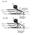
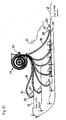
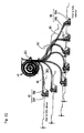
- the flexible tube 18 is not severely bent at a mouth portion of the door side fixing unit 16 at the time that the sliding door 12 is fully opened or fully closed, thus there is no tendency to be habitually bent in a specific portion of the flexible tube 18.
- the third embodiment is the same as the first embodiment.
- the detail explanation is omitted with the same reference numerals used. According to the third embodiment, the same effect can be obtained as that of the first embodiment.
- the case of the extra-length wire harness absorbing unit comprises a lower case, an upper case, and a sub-cover for fixing an inner peripheral portion of a wound wire harness in spiral to a center portion of the case, a main axis portion inserted into a hollow axis portion of the rotating drum is formed in the lower case, the sub-cover is attached to the main axis and the coiled spring is incorporated between the lower case and the rotating drum, the extra-length absorbing unit may be easily assembled.
- the coiled spring it is possible to prevent the spring from being bigger size compared with the case in which the spiral spring is used.
- the main axis is provided, the strength of the case in upward and downward direction may become higher.
Applications Claiming Priority (4)
| Application Number | Priority Date | Filing Date | Title |
|---|---|---|---|
| JP2004160403 | 2004-05-31 | ||
| JP2004160403 | 2004-05-31 | ||
| JP2004352285A JP4667844B2 (ja) | 2004-05-31 | 2004-12-06 | スライドドア用給電装置 |
| JP2004352285 | 2004-12-06 |
Publications (2)
| Publication Number | Publication Date |
|---|---|
| EP1602518A2 true EP1602518A2 (fr) | 2005-12-07 |
| EP1602518A3 EP1602518A3 (fr) | 2011-03-09 |
Family
ID=34942604
Family Applications (1)
| Application Number | Title | Priority Date | Filing Date |
|---|---|---|---|
| EP05300368A Withdrawn EP1602518A3 (fr) | 2004-05-31 | 2005-05-11 | Dispositif d'alimentation de puissance pour porte coulissante |
Country Status (3)
| Country | Link |
|---|---|
| US (1) | US7086687B2 (fr) |
| EP (1) | EP1602518A3 (fr) |
| JP (1) | JP4667844B2 (fr) |
Cited By (6)
| Publication number | Priority date | Publication date | Assignee | Title |
|---|---|---|---|---|
| US8493081B2 (en) | 2009-12-08 | 2013-07-23 | Magna Closures Inc. | Wide activation angle pinch sensor section and sensor hook-on attachment principle |
| US9234979B2 (en) | 2009-12-08 | 2016-01-12 | Magna Closures Inc. | Wide activation angle pinch sensor section |
| EP3043434A1 (fr) * | 2013-09-06 | 2016-07-13 | Yazaki Corporation | Structure d'alimentation électrique pour une porte coulissante |
| WO2017003562A1 (fr) * | 2015-06-30 | 2017-01-05 | Fca Us Llc | Ensemble rail de guidage pour porte coulissante de véhicule |
| WO2019192759A1 (fr) * | 2018-04-05 | 2019-10-10 | Krones Ag | Dispositif de fixation de câble pour installation de traitement de récipients et procédé pour le réglage d'un rayon de courbure minimal pour un câble de connexion d'une installation de traitement de récipients |
| DE102016214430B4 (de) | 2015-08-04 | 2021-11-18 | Yazaki Corporation | Kabelbaum-Wickelvorrichtung |
Families Citing this family (31)
| Publication number | Priority date | Publication date | Assignee | Title |
|---|---|---|---|---|
| JP2006257764A (ja) * | 2005-03-17 | 2006-09-28 | Asmo Co Ltd | 自走式開閉装置 |
| CN101242973B (zh) * | 2005-09-05 | 2010-05-19 | 古河电气工业株式会社 | 滑动门用供电装置 |
| KR100737469B1 (ko) * | 2005-12-07 | 2007-07-09 | 기아자동차주식회사 | 차량의 무빙 와이어링 시스템 |
| JP4997944B2 (ja) * | 2006-03-07 | 2012-08-15 | 日産自動車株式会社 | 給電ユニット |
| JP4804988B2 (ja) * | 2006-03-31 | 2011-11-02 | 古河電気工業株式会社 | スライドドア用給電装置の取付方法 |
| JP2008030716A (ja) * | 2006-07-31 | 2008-02-14 | Furukawa Electric Co Ltd:The | スライドドア用給電装置 |
| WO2008015935A1 (fr) | 2006-07-31 | 2008-02-07 | The Furukawa Electric Co., Ltd. | Dispositif de fourniture d'électricité pour porte coulissante |
| JP4702849B2 (ja) * | 2006-08-14 | 2011-06-15 | 古河電気工業株式会社 | スライドドア用給電装置 |
| JP4783307B2 (ja) * | 2006-11-13 | 2011-09-28 | 矢崎総業株式会社 | スライド構造体用の給電装置 |
| JP4728938B2 (ja) | 2006-12-08 | 2011-07-20 | 古河電気工業株式会社 | スライドドア用給電装置 |
| JP4913690B2 (ja) * | 2007-07-27 | 2012-04-11 | 古河電気工業株式会社 | スライドドア用給電装置 |
| JP4956406B2 (ja) * | 2007-12-21 | 2012-06-20 | 古河電気工業株式会社 | 回転コネクタ装置 |
| JP4908630B2 (ja) | 2008-03-14 | 2012-04-04 | 矢崎総業株式会社 | 給電装置のプロテクタ構造 |
| EP2360062B1 (fr) * | 2008-12-16 | 2016-09-28 | Yazaki Corporation | Dispositif de câblage de harnais |
| JP5378826B2 (ja) * | 2009-02-17 | 2013-12-25 | 矢崎総業株式会社 | 電線配索装置 |
| DE102009037674A1 (de) * | 2009-08-14 | 2011-02-17 | Brose Fahrzeugteile Gmbh & Co. Kommanditgesellschaft, Hallstadt | Fensterheberbaugruppe für ein Kraftfahrzeug |
| JP5338635B2 (ja) * | 2009-11-20 | 2013-11-13 | アイシン精機株式会社 | 配線保持構造 |
| US8604343B2 (en) | 2010-06-17 | 2013-12-10 | Karen Nixon-Lane | Window compatible electrical power device |
| JP5978942B2 (ja) * | 2012-11-16 | 2016-08-24 | ブラザー工業株式会社 | 画像読取装置 |
| JP6145771B2 (ja) * | 2013-06-20 | 2017-06-14 | 矢崎総業株式会社 | ワイヤハーネス |
| JP6146909B2 (ja) * | 2013-10-11 | 2017-06-14 | 矢崎総業株式会社 | 給電装置及び給電装置の組立方法 |
| JP6513954B2 (ja) * | 2015-01-23 | 2019-05-15 | 矢崎総業株式会社 | 給電装置 |
| DE102016203310A1 (de) * | 2015-03-02 | 2016-09-08 | Yazaki Corporation | Kabelbaum-Verlegestruktur |
| JP6488981B2 (ja) * | 2015-10-13 | 2019-03-27 | 住友電装株式会社 | 電線配索装置 |
| JP6793545B2 (ja) | 2016-12-28 | 2020-12-02 | 矢崎総業株式会社 | 巻取装置及び配索構造 |
| KR102507945B1 (ko) * | 2018-03-26 | 2023-03-09 | 후루카와 덴키 고교 가부시키가이샤 | 케이블 권취 장치 및 슬라이드 시트용 플랫 케이블 라우팅 구조 |
| JP7166077B2 (ja) * | 2018-06-06 | 2022-11-07 | 矢崎総業株式会社 | 屈曲プロテクタ |
| JP6902008B2 (ja) * | 2018-10-24 | 2021-07-14 | 矢崎総業株式会社 | シート付ハーネス |
| JP7155190B2 (ja) * | 2020-04-06 | 2022-10-18 | 矢崎総業株式会社 | スライドシート用の配索構造 |
| WO2022113479A1 (fr) * | 2020-11-30 | 2022-06-02 | 古河電気工業株式会社 | Dispositif pour alimenter en énergie une porte coulissante |
| KR20240021008A (ko) * | 2022-08-09 | 2024-02-16 | 주식회사 광진 | 자동차용 윈도우 전원공급장치 |
Citations (2)
| Publication number | Priority date | Publication date | Assignee | Title |
|---|---|---|---|---|
| JPH1193514A (ja) | 1997-07-25 | 1999-04-06 | Toyota Auto Body Co Ltd | 車両用スライドドアの給電構造 |
| JP2002079892A (ja) | 2000-06-30 | 2002-03-19 | Yazaki Corp | スライドドアへのハーネス配索構造 |
Family Cites Families (15)
| Publication number | Priority date | Publication date | Assignee | Title |
|---|---|---|---|---|
| DE19717490A1 (de) * | 1997-04-25 | 1998-10-29 | Kiekert Ag | Kraftfahrzeug |
| JP2000297579A (ja) * | 1999-04-16 | 2000-10-24 | Yazaki Corp | 自動車用スライドドアの給電装置 |
| JP3914374B2 (ja) * | 2000-06-19 | 2007-05-16 | 矢崎総業株式会社 | スライドドアの給電構造 |
| JP3895908B2 (ja) * | 2000-06-30 | 2007-03-22 | 矢崎総業株式会社 | スライドドア用ハーネスの配索構造 |
| JP3467465B2 (ja) * | 2000-09-27 | 2003-11-17 | 矢崎総業株式会社 | ワイヤーハーネス巻取り装置の異物排出構造 |
| DE60206090T2 (de) * | 2001-03-16 | 2006-06-14 | Yazaki Corp | Kabelbaumanordnung für eine Kraftfahrzeugschiebetür |
| JP3861163B2 (ja) * | 2001-07-12 | 2006-12-20 | 日産自動車株式会社 | スライドドア給電構造 |
| ITTO20011100A1 (it) * | 2001-11-23 | 2003-05-23 | Framatome Connectors Italia | Gruppo di connessione per il collegamento di un impianto elettrico diun autoveicolo a componenti elettrici di una portiera scorrevole dell' |
| JP2003189451A (ja) * | 2001-12-11 | 2003-07-04 | Yazaki Corp | ハーネス弛み吸収装置 |
| GB0203941D0 (en) * | 2002-02-20 | 2002-04-03 | Meritor Light Vehicle Sys Ltd | A vehicle |
| JP3940308B2 (ja) * | 2002-03-27 | 2007-07-04 | 矢崎総業株式会社 | ハーネス固定具 |
| JP4077276B2 (ja) * | 2002-03-29 | 2008-04-16 | 矢崎総業株式会社 | スライドドア用給電装置 |
| US6793259B2 (en) * | 2002-03-29 | 2004-09-21 | Yazaki Corporation | Electric wire excess length absorbing device and sliding door-use power feeding apparatus using the same |
| JP4098615B2 (ja) * | 2002-05-20 | 2008-06-11 | 矢崎総業株式会社 | スライド構造体の給電装置 |
| JP2004345598A (ja) * | 2003-05-26 | 2004-12-09 | Furukawa Electric Co Ltd:The | スライドドア用給電装置 |
-
2004
- 2004-12-06 JP JP2004352285A patent/JP4667844B2/ja active Active
-
2005
- 2005-05-06 US US11/123,043 patent/US7086687B2/en active Active
- 2005-05-11 EP EP05300368A patent/EP1602518A3/fr not_active Withdrawn
Patent Citations (2)
| Publication number | Priority date | Publication date | Assignee | Title |
|---|---|---|---|---|
| JPH1193514A (ja) | 1997-07-25 | 1999-04-06 | Toyota Auto Body Co Ltd | 車両用スライドドアの給電構造 |
| JP2002079892A (ja) | 2000-06-30 | 2002-03-19 | Yazaki Corp | スライドドアへのハーネス配索構造 |
Cited By (12)
| Publication number | Priority date | Publication date | Assignee | Title |
|---|---|---|---|---|
| US8493081B2 (en) | 2009-12-08 | 2013-07-23 | Magna Closures Inc. | Wide activation angle pinch sensor section and sensor hook-on attachment principle |
| US9234979B2 (en) | 2009-12-08 | 2016-01-12 | Magna Closures Inc. | Wide activation angle pinch sensor section |
| US9417099B2 (en) | 2009-12-08 | 2016-08-16 | Magna Closures Inc. | Wide activation angle pinch sensor section |
| EP3043434A1 (fr) * | 2013-09-06 | 2016-07-13 | Yazaki Corporation | Structure d'alimentation électrique pour une porte coulissante |
| EP3043434A4 (fr) * | 2013-09-06 | 2017-04-26 | Yazaki Corporation | Structure d'alimentation électrique pour une porte coulissante |
| WO2017003562A1 (fr) * | 2015-06-30 | 2017-01-05 | Fca Us Llc | Ensemble rail de guidage pour porte coulissante de véhicule |
| US9956928B2 (en) | 2015-06-30 | 2018-05-01 | Fca Us Llc | Track assembly for sliding vehicle door |
| DE102016214430B4 (de) | 2015-08-04 | 2021-11-18 | Yazaki Corporation | Kabelbaum-Wickelvorrichtung |
| WO2019192759A1 (fr) * | 2018-04-05 | 2019-10-10 | Krones Ag | Dispositif de fixation de câble pour installation de traitement de récipients et procédé pour le réglage d'un rayon de courbure minimal pour un câble de connexion d'une installation de traitement de récipients |
| CN111937262A (zh) * | 2018-04-05 | 2020-11-13 | 德国克朗斯公司 | 用于容器处理设备的线缆紧固装置和用于调节容器处理设备的连接线缆的最小弯曲半径的方法 |
| CN111937262B (zh) * | 2018-04-05 | 2021-12-31 | 德国克朗斯公司 | 线缆紧固装置和用于调节连接线缆的最小弯曲半径的方法 |
| US11742642B2 (en) | 2018-04-05 | 2023-08-29 | Krones Ag | Cable fixing device for container handling system and method for setting a minimum bending radius for a connecting cable of a container handling system |
Also Published As
| Publication number | Publication date |
|---|---|
| JP4667844B2 (ja) | 2011-04-13 |
| JP2006015981A (ja) | 2006-01-19 |
| US7086687B2 (en) | 2006-08-08 |
| EP1602518A3 (fr) | 2011-03-09 |
| US20050264033A1 (en) | 2005-12-01 |
Similar Documents
| Publication | Publication Date | Title |
|---|---|---|
| US7086687B2 (en) | Power supply device for a sliding door | |
| US7600800B2 (en) | Storage structure at rear part of vehicle interior | |
| CN105794063B (zh) | 线束 | |
| US7246838B2 (en) | Trailer cover system | |
| EP1605568A1 (fr) | Dispositif de fixation de faisceau pour l'alimentation de porte coulissante et structure d'alimentation utilisant un tel dispositif | |
| US7159930B2 (en) | Power slide device for vehicle sliding door | |
| US7339112B2 (en) | Electric supply device | |
| US20080042466A1 (en) | Trailer cover system | |
| KR101232563B1 (ko) | 힌지 구조체 | |
| FR2842958A1 (fr) | Dispositif de cablage d'alimentation de puissance et structure d'agencement de faisceau utilisant le dispositif de cablage d'alimentation de puissance | |
| EP2950409B1 (fr) | Dispositif d'alimentation électrique | |
| KR102607730B1 (ko) | 대향형 슬라이딩 도어가 장착된 차량의 사이드실 구조 | |
| WO2007043225A1 (fr) | Dispositif de support de cable | |
| EP2950408B1 (fr) | Structure protectrice de partie ressort pour dispositifs d'alimentation électriques | |
| CN110185354B (zh) | 车窗调节器 | |
| US8172301B2 (en) | Trailer cover system | |
| JP4492550B2 (ja) | スイングスライドドアの配索構造 | |
| US20200256111A1 (en) | Window regulator | |
| US10975604B2 (en) | Window regulator | |
| JPH11122791A (ja) | 開閉部材構造 | |
| CN211617628U (zh) | 安全带下固定部、安全带总成及汽车 | |
| JP4047627B2 (ja) | プロテクタ | |
| JP4826943B2 (ja) | ウイングルーフコンテナ | |
| JP2012193515A (ja) | ローラユニット | |
| JP2024064809A (ja) | 対象物移動装置およびウインドレギュレータ |
Legal Events
| Date | Code | Title | Description |
|---|---|---|---|
| PUAI | Public reference made under article 153(3) epc to a published international application that has entered the european phase |
Free format text: ORIGINAL CODE: 0009012 |
|
| AK | Designated contracting states |
Kind code of ref document: A2 Designated state(s): AT BE BG CH CY CZ DE DK EE ES FI FR GB GR HU IE IS IT LI LT LU MC NL PL PT RO SE SI SK TR |
|
| AX | Request for extension of the european patent |
Extension state: AL BA HR LV MK YU |
|
| PUAL | Search report despatched |
Free format text: ORIGINAL CODE: 0009013 |
|
| AK | Designated contracting states |
Kind code of ref document: A3 Designated state(s): AT BE BG CH CY CZ DE DK EE ES FI FR GB GR HU IE IS IT LI LT LU MC NL PL PT RO SE SI SK TR |
|
| AX | Request for extension of the european patent |
Extension state: AL BA HR LV MK YU |
|
| RIC1 | Information provided on ipc code assigned before grant |
Ipc: B60R 16/02 20060101ALI20110128BHEP Ipc: H02G 11/02 20060101ALI20110128BHEP Ipc: E05F 15/14 20060101ALI20110128BHEP Ipc: B60J 5/06 20060101AFI20050913BHEP |
|
| AKY | No designation fees paid | ||
| REG | Reference to a national code |
Ref country code: DE Ref legal event code: R108 |
|
| REG | Reference to a national code |
Ref country code: DE Ref legal event code: R108 Effective date: 20111116 |
|
| STAA | Information on the status of an ep patent application or granted ep patent |
Free format text: STATUS: THE APPLICATION IS DEEMED TO BE WITHDRAWN |
|
| 18D | Application deemed to be withdrawn |
Effective date: 20110910 |