EP1602518A2 - Power supply device for sliding door - Google Patents
Power supply device for sliding door Download PDFInfo
- Publication number
- EP1602518A2 EP1602518A2 EP05300368A EP05300368A EP1602518A2 EP 1602518 A2 EP1602518 A2 EP 1602518A2 EP 05300368 A EP05300368 A EP 05300368A EP 05300368 A EP05300368 A EP 05300368A EP 1602518 A2 EP1602518 A2 EP 1602518A2
- Authority
- EP
- European Patent Office
- Prior art keywords
- sliding door
- rotating drum
- flexible tube
- case
- coiled spring
- Prior art date
- Legal status (The legal status is an assumption and is not a legal conclusion. Google has not performed a legal analysis and makes no representation as to the accuracy of the status listed.)
- Withdrawn
Links
Images


Classifications
-
- B—PERFORMING OPERATIONS; TRANSPORTING
- B60—VEHICLES IN GENERAL
- B60R—VEHICLES, VEHICLE FITTINGS, OR VEHICLE PARTS, NOT OTHERWISE PROVIDED FOR
- B60R16/00—Electric or fluid circuits specially adapted for vehicles and not otherwise provided for; Arrangement of elements of electric or fluid circuits specially adapted for vehicles and not otherwise provided for
- B60R16/02—Electric or fluid circuits specially adapted for vehicles and not otherwise provided for; Arrangement of elements of electric or fluid circuits specially adapted for vehicles and not otherwise provided for electric constitutive elements
- B60R16/0207—Wire harnesses
- B60R16/0215—Protecting, fastening and routing means therefor
-
- B—PERFORMING OPERATIONS; TRANSPORTING
- B60—VEHICLES IN GENERAL
- B60R—VEHICLES, VEHICLE FITTINGS, OR VEHICLE PARTS, NOT OTHERWISE PROVIDED FOR
- B60R16/00—Electric or fluid circuits specially adapted for vehicles and not otherwise provided for; Arrangement of elements of electric or fluid circuits specially adapted for vehicles and not otherwise provided for
- B60R16/02—Electric or fluid circuits specially adapted for vehicles and not otherwise provided for; Arrangement of elements of electric or fluid circuits specially adapted for vehicles and not otherwise provided for electric constitutive elements
- B60R16/023—Electric or fluid circuits specially adapted for vehicles and not otherwise provided for; Arrangement of elements of electric or fluid circuits specially adapted for vehicles and not otherwise provided for electric constitutive elements for transmission of signals between vehicle parts or subsystems
- B60R16/027—Electric or fluid circuits specially adapted for vehicles and not otherwise provided for; Arrangement of elements of electric or fluid circuits specially adapted for vehicles and not otherwise provided for electric constitutive elements for transmission of signals between vehicle parts or subsystems between relatively movable parts of the vehicle, e.g. between steering wheel and column
-
- E—FIXED CONSTRUCTIONS
- E05—LOCKS; KEYS; WINDOW OR DOOR FITTINGS; SAFES
- E05D—HINGES OR SUSPENSION DEVICES FOR DOORS, WINDOWS OR WINGS
- E05D11/00—Additional features or accessories of hinges
- E05D11/0081—Additional features or accessories of hinges for transmitting energy, e.g. electrical cable routing
-
- E—FIXED CONSTRUCTIONS
- E05—LOCKS; KEYS; WINDOW OR DOOR FITTINGS; SAFES
- E05F—DEVICES FOR MOVING WINGS INTO OPEN OR CLOSED POSITION; CHECKS FOR WINGS; WING FITTINGS NOT OTHERWISE PROVIDED FOR, CONCERNED WITH THE FUNCTIONING OF THE WING
- E05F15/00—Power-operated mechanisms for wings
- E05F15/60—Power-operated mechanisms for wings using electrical actuators
- E05F15/603—Power-operated mechanisms for wings using electrical actuators using rotary electromotors
- E05F15/632—Power-operated mechanisms for wings using electrical actuators using rotary electromotors for horizontally-sliding wings
-
- F—MECHANICAL ENGINEERING; LIGHTING; HEATING; WEAPONS; BLASTING
- F16—ENGINEERING ELEMENTS AND UNITS; GENERAL MEASURES FOR PRODUCING AND MAINTAINING EFFECTIVE FUNCTIONING OF MACHINES OR INSTALLATIONS; THERMAL INSULATION IN GENERAL
- F16L—PIPES; JOINTS OR FITTINGS FOR PIPES; SUPPORTS FOR PIPES, CABLES OR PROTECTIVE TUBING; MEANS FOR THERMAL INSULATION IN GENERAL
- F16L3/00—Supports for pipes, cables or protective tubing, e.g. hangers, holders, clamps, cleats, clips, brackets
- F16L3/01—Supports for pipes, cables or protective tubing, e.g. hangers, holders, clamps, cleats, clips, brackets for supporting or guiding the pipes, cables or protective tubing, between relatively movable points, e.g. movable channels
- F16L3/015—Supports for pipes, cables or protective tubing, e.g. hangers, holders, clamps, cleats, clips, brackets for supporting or guiding the pipes, cables or protective tubing, between relatively movable points, e.g. movable channels using articulated- or supple-guiding elements
-
- H—ELECTRICITY
- H02—GENERATION; CONVERSION OR DISTRIBUTION OF ELECTRIC POWER
- H02G—INSTALLATION OF ELECTRIC CABLES OR LINES, OR OF COMBINED OPTICAL AND ELECTRIC CABLES OR LINES
- H02G11/00—Arrangements of electric cables or lines between relatively-movable parts
- H02G11/006—Arrangements of electric cables or lines between relatively-movable parts using extensible carrier for the cable, e.g. self-coiling spring
-
- E—FIXED CONSTRUCTIONS
- E05—LOCKS; KEYS; WINDOW OR DOOR FITTINGS; SAFES
- E05F—DEVICES FOR MOVING WINGS INTO OPEN OR CLOSED POSITION; CHECKS FOR WINGS; WING FITTINGS NOT OTHERWISE PROVIDED FOR, CONCERNED WITH THE FUNCTIONING OF THE WING
- E05F15/00—Power-operated mechanisms for wings
- E05F15/40—Safety devices, e.g. detection of obstructions or end positions
- E05F15/42—Detection using safety edges
- E05F15/44—Detection using safety edges responsive to changes in electrical conductivity
- E05F2015/447—Detection using safety edges responsive to changes in electrical conductivity using switches in serial arrangement
-
- E—FIXED CONSTRUCTIONS
- E05—LOCKS; KEYS; WINDOW OR DOOR FITTINGS; SAFES
- E05Y—INDEXING SCHEME RELATING TO HINGES OR OTHER SUSPENSION DEVICES FOR DOORS, WINDOWS OR WINGS AND DEVICES FOR MOVING WINGS INTO OPEN OR CLOSED POSITION, CHECKS FOR WINGS AND WING FITTINGS NOT OTHERWISE PROVIDED FOR, CONCERNED WITH THE FUNCTIONING OF THE WING
- E05Y2400/00—Electronic control; Power supply; Power or signal transmission; User interfaces
- E05Y2400/60—Power supply; Power or signal transmission
- E05Y2400/65—Power or signal transmission
- E05Y2400/654—Power or signal transmission by electrical cables
-
- E—FIXED CONSTRUCTIONS
- E05—LOCKS; KEYS; WINDOW OR DOOR FITTINGS; SAFES
- E05Y—INDEXING SCHEME RELATING TO HINGES OR OTHER SUSPENSION DEVICES FOR DOORS, WINDOWS OR WINGS AND DEVICES FOR MOVING WINGS INTO OPEN OR CLOSED POSITION, CHECKS FOR WINGS AND WING FITTINGS NOT OTHERWISE PROVIDED FOR, CONCERNED WITH THE FUNCTIONING OF THE WING
- E05Y2800/00—Details, accessories and auxiliary operations not otherwise provided for
- E05Y2800/34—Form stability
- E05Y2800/342—Deformable
- E05Y2800/344—Deformable elastically
-
- E—FIXED CONSTRUCTIONS
- E05—LOCKS; KEYS; WINDOW OR DOOR FITTINGS; SAFES
- E05Y—INDEXING SCHEME RELATING TO HINGES OR OTHER SUSPENSION DEVICES FOR DOORS, WINDOWS OR WINGS AND DEVICES FOR MOVING WINGS INTO OPEN OR CLOSED POSITION, CHECKS FOR WINGS AND WING FITTINGS NOT OTHERWISE PROVIDED FOR, CONCERNED WITH THE FUNCTIONING OF THE WING
- E05Y2900/00—Application of doors, windows, wings or fittings thereof
- E05Y2900/50—Application of doors, windows, wings or fittings thereof for vehicles
- E05Y2900/53—Application of doors, windows, wings or fittings thereof for vehicles characterised by the type of wing
- E05Y2900/531—Doors
-
- H—ELECTRICITY
- H02—GENERATION; CONVERSION OR DISTRIBUTION OF ELECTRIC POWER
- H02G—INSTALLATION OF ELECTRIC CABLES OR LINES, OR OF COMBINED OPTICAL AND ELECTRIC CABLES OR LINES
- H02G3/00—Installations of electric cables or lines or protective tubing therefor in or on buildings, equivalent structures or vehicles
- H02G3/02—Details
- H02G3/04—Protective tubing or conduits, e.g. cable ladders or cable troughs
- H02G3/0462—Tubings, i.e. having a closed section
- H02G3/0468—Corrugated
Landscapes
- Engineering & Computer Science (AREA)
- Mechanical Engineering (AREA)
- General Engineering & Computer Science (AREA)
- Electric Cable Arrangement Between Relatively Moving Parts (AREA)
Abstract
Description
- The present invention relates to a power supply device for a sliding door for supplying power or transmitting signals to the devices installed in the sliding door from the vehicle body side of the car.
- Devices such as a power window motor, switches, speaker or the like are incorporated inside of the sliding door used for a one-box car, wagon or the like. To supply power from the vehicle body side to the devices, it is necessary to wire a cable (wire harness) from the vehicle body to the sliding door, in addition, to cause the cable to follow the opening and closing of the sliding door.
- It is known as this kind of the power supply device for a sliding door that a cable winding unit is installed in the vehicle body side and the extra-length cable which is caused in accordance with the opening and closing of the sliding door is absorbed by winding the cable (refer to Japanese Patent Provisional Publication No. 11-93514).
- It is known as other kind of the power supply device for a sliding door that a flexible tube receiving a wire harness is wired with extendible for bent between a prescribed position of the vehicle side and the sliding door, one end of the flexible tube is fixed to the sliding door and the vicinity of the other end of the flexible tube is pivotably supported by the metallic part fixed to the vehicle body (refer to Japanese Patent Provisional Publication No. 2002-79892).
- However, in the power supply device for a sliding door as disclosed in Japanese Patent Provisional Publication No. 11-93514, the cable per se is pulled out of the winding unit, and the cable is likely damaged by interfering with other members (i.e., sliding rail). Furthermore, since the winding unit has to pull out or wind the cable having the same length as the stroke of the opening and closing of the sliding door, thus the device becomes bigger.
- In addition, in the power supply device for a sliding door as disclosed in Japanese Patent Provisional Publication No. 2002-79892, since the wire harness is received in the flexible tube, the wire harness is not likely damaged. However, the flexible tube receiving the wire harness is necessary to have a sufficient length to absorb the stroke of opening and closing of the sliding door, thus a large space is necessary to wire such a long flexible tube receiving the wire harness with extendible length for bent. Furthermore, when the flexible tube is loosed and interfered with other members, the flexible tube with wire harness is likely damaged, and the noise is generated.
- One of the object of the invention is to provide a power supply device for a sliding door enabling to be downsized, in which the flexible tube and wire harness received therein ranging from the vehicle body side to the sliding door is not likely damaged, and the flexible tube is bent and moved in a relatively small space.
- A power supply device for a sliding door of the invention comprises an extra-length absorbing unit, a door side fixing unit fixed to a sliding door, a flexible tube extending from said extra-length absorbing unit to said door side fixing unit, and a wire harness wired from a vehicle body through said extra-length absorbing unit, said flexible tube and said door side fixing unit to the sliding door,
wherein said extra-length absorbing unit includes a case having a gate for said flexible tube, a rotating drum for winding said flexible tube in the case, and a torsion spring for providing a turning force with said rotating drum in a winding direction of said flexible tube, an end portion at the vehicle body of said flexible tube being fixed on the rotating drum, a portion at the vehicle side of said wire harness being fixed to the rotating drum in a vicinity of the end portion of said flexible tube, said flexible tube being wound in spiral within the rotating drum, a spiral inner peripheral portion thereof being fixed to a center portion of the case, and said flexible tube being pulled out of the case through the gate,
said door side fixing unit holds a sliding door side end portion of said flexible tube, a sliding door side portion of said wire harness being pulled out of the end portion of the flexible tube into the sliding door, and
said extra-length absorbing unit is fixed to the vehicle body so as to be located in an intermediate position of a moving range of the door side fixing unit by an opening and closing movements of the sliding door, said flexible tube being provided with a tensile force by the turning force of the rotating drum from the extra-length absorbing unit to said door side fixing unit. - As the torsion spring of the extra-length absorbing unit, a coiled spring or a spiral spring may be used, however, the coiled spring is preferable in view of down-sizing, and easy designing.
- In the power supply device for a sliding door of the invention, said wire harness comprises one sheet or plurality sheets of flat cable, said flexible tube comprises a corrugated tube having a cross section of a longer vertical portion than a horizontal portion in which said one sheet or plurality sheets of flat cable are received with the width thereof vertically directed. The corrugated tube preferably includes a rib formed running along a longitudinal direction on at least one of an upper surface and lower surface thereof.
- In the power supply device for a sliding door of the invention, a guide for restricting a bend radius of said flexible tube within a prescribed range is provided on the gate for the flexible tube in said extra-length absorbing unit. A reinforcing wall portion for preventing the guide from flexing is preferably provided at a back side of said guide.
- In the power supply device for a sliding door of the invention, said door side fixing unit is fixed to the sliding door in such manner that said flexible tube goes out to a forward direction or a backward direction of the sliding door, and a guide for restricting a bend radius of said flexible tube within a prescribed range is preferably provided in a vicinity of an exit port of said flexible tube in said extra-length absorbing unit.
- In the power supply device for a sliding door of the invention, said door side fixing unit comprises a fixing member for being fixed to the sliding door, a tube end clamp for being pivotably fixed in a plane perpendicular to a longitudinal axis of the fixing member, and a restricting portion for restricting the tube end clamp to pivot within a prescribed range may be provided with said fixing member.
- In the power supply device for a sliding door of the invention, the case of said extra-length wire harness absorbing nit comprises a lower case, an upper case, and a sub-cover for fixing an inner peripheral portion of a wound wire harness in spiral to a center portion of the case, a main axis portion inserted into a hollow axis portion of the rotating drum is formed in the lower case, a central cylindrical portion is formed in the upper case so as to be positioned at an outer peripheral of the hollow axis portion of the rotating drum, the sub-cover is attached to the central cylindrical portion so as not to rotate, the torsion spring comprises a coiled spring, and the coiled spring is preferably incorporated between the lower case and the rotating drum in such condition that the coiled spring is turned so that the turning force is given to the rotating drum in a direction of winding the flexible tube.
- In the power supply device for a sliding door of the invention, the case of said extra-length wire harness absorbing nit comprises a lower case, an upper case, and a sub-cover for fixing an inner peripheral portion of a wound wire harness in spiral to a center portion of the case, a main axis portion inserted into a hollow axis portion of the rotating drum is formed in the lower case, the sub-cover is attached to the main axis portion so as not to rotate, the torsion spring of the extra-length absorbing unit comprises a coiled spring, and the coiled spring is preferably incorporated between the lower case and the rotating drum in such condition that the coiled spring is turned so that the turning force is given to the rotating drum in a direction of winding the flexible tube.
- In the power supply device for a sliding door of the invention, a stopper for restricting a rotation angle of the rotating drum is preferably provided respectively on a lower surface of a bottom portion of the rotating drum, and a corresponding upper surface of a bottom portion of the lower case.
- In the power supply device for a sliding door of the invention, a cutout portion for preventing foreign material from being collected is provided on a bottom portion in the case for the gate of the flexible tube, a gap larger than a size of foreign material likely entering into the case is provided between the case and the rotating drum, a slant surface and a through hole are formed on the bottom surface of the lower case so as to discharge the foreign material entered into the case, and a rib is preferably provided on a coiled spring receiving portion so that the coiled spring is placed with a space from the bottom surface of the lower case.
- In the power supply device for a sliding door of the invention, an extended piece for restricting upward and downward movement of the flexible tube wound around the rotating drum is preferably provided on an upper end portion of the rotating drum toward outward thereof.
- In the power supply device for a sliding door of the invention, the sub-cover preferably includes a fitting portion for fitting to an upper end of the main axis portion of the lower case and a guide passage for guiding the flat cable over the rotating drum to outside of the case, outer end of the guide passage being fixed to an outer peripheral portion of the lower case. In this case, a groove-shaped cover portion is preferably formed on the upper case, to which an upper face of the sub-cover is fitted.
- In the power supply device for a sliding door of the invention, an opening portion is preferably formed, for easy assembling, on a bottom plate portion of the rotating drum at a position corresponding to a portion to which an end portion of the coiled spring is come into contact.
- In the power supply device for a sliding door of the invention, an upper end of the coiled spring is positioned above a lower end of the coiled spring receiving portion, and a distance (Q) from the upper end of the coiled spring to the upper end face of the coiled spring receiving portion of the rotating drum is formed so as to be larger than a distance (R) from the upper end of the coiled spring to the lower end of the coiled spring receiving portion of the rotating drum, when the upper face of the stopper provided in the lower case for restricting the rotation angle is contacted with the lower face of the stopper provided in the rotating drum for restricting the rotation angle in assembling of the rotating drum, the lower case and the coiled spring.
- In the power supply device for a sliding door of the invention, the rotating drum, the lower case and the coiled spring are preferably formed, for easy assembling, in such manner that a coiled spring which is not turned and a lower case are arranged so as not to be relatively rotated, and a coiled spring which is not turned and a rotating drum are arranged so as not to be relatively rotated, thus, the upper face of the stopper provided in the lower case for restricting the rotation angle is contacted with the lower face of the stopper provided in the rotating drum for restricting the rotation angle, and then, the rotating drum is turned in a direction to give a prescribed rotation angle to the coiled spring and is pushed toward the lower case, thus the stopper in the lower case is engaged to the stopper in the rotating drum.
-
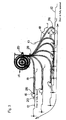
- Fig. 1 is a schematic oblique view showing the power supply device for a sliding door of the invention as a whole;
- Fig. 2 is a plan view showing one embodiment of the power supply device for a sliding door of the invention together with the sliding door fully closed and fully opened;
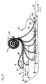
- Fig. 3 is a plan view showing a trace of the bent flexible tube which moves from the point in which the sliding door is fully closed to the point in which the sliding door is fully opened;
- Fig. 4 is an oblique view from the upper side showing an extra-length absorbing unit applied to the power supply device for a sliding door of the invention as shown in Fig. 2;
- Fig. 5 is an oblique view from the lower side showing an extra-length absorbing unit applied to the power supply device for a sliding door of the invention;
- Fig. 6 is an oblique disassembled view of an extra-length absorbing unit applied to the power supply device for a sliding door of the invention;
- Fig. 7 is a cross sectional view of an extra-length absorbing unit applied to the power supply device for a sliding door of the invention;
- Fig. 8A is an oblique view showing a preferable embodiment of a flexible tube of the invention, Fig. 8B is a front view showing a preferable embodiment of a flexible tube of the invention;
- Fig. 9 is an oblique view showing a preferable embodiment of a gate in the case for the flexible tube;
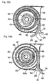
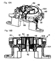
- Fig. 10A is a plan view showing the inside of the extra-length absorbing unit applied to the power supply device for a sliding door of the invention as shown in Fig. 2 in which the sliding door is fully closed, Fig. 10B is a plan view showing the inside of the extra-length absorbing unit in which the sliding door is fully opened;
- Fig. 11 is an oblique view showing the opposing faces of the lower case and the rotating drum of the extra-length absorbing unit;
- Fig. 12 is a plan view showing the rotation angle of the rotating drum and the absorbed extra-length of the flexible tube;
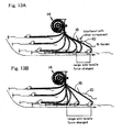
- Fig. 13A is a view explaining the flexible tube with weak tensile strength when the sliding door is fully opened, Fig. 13B is a view explaining the flexible tube with tensile strength applied prior to the full opening of the sliding door;
- Fig. 14 is an oblique view showing the situation in which the cutout portion is provided on the bottom portion of the gate in the case for the flexible tube;
- Fig. 15A is a cross sectional view showing a gap along the axis between the lower case and the rotating drum, Fig. 15B is a cross sectional view along B-B line showing a gap along the radius direction between the lower case and the rotating drum;
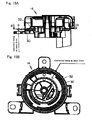
- Fig. 16A is a cross sectional view showing a discharge structure for foreign material entered into the case, Fig. 16B shows a bottom face of the discharge structure;
- Fig. 17A is an oblique view showing a structure of preventing a noise in the extra-length absorbing unit, Fig. 17B is a plan view showing a structure of preventing a noise in the extra-length absorbing unit;
- Fig. 18A is an oblique view showing a preferable embodiment of the sub-cover, Fig. 18B is a cross sectional view thereof;
- Fig. 19 is an oblique view showing a preferable embodiment of the rotating drum;
- Fig. 20A is a cross sectional view showing a preferable embodiment of the rotating drum, lower case and coiled spring in the way of the assembling, Fig. 20B is a cross sectional view showing a preferable embodiment of the rotating drum, lower case and coiled spring after assembled;
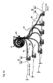
- Fig. 21 is a plan view showing another embodiment of the power supply device for a sliding door of the invention together with a trace of the bent flexible tube which moves from the point in which the sliding door is fully closed to the point in which the sliding door is fully opened;
- Fig. 22 is a plan view showing other embodiment of the power supply device for a sliding door of the invention together with a trace of the bent flexible tube which moves from the point in which the sliding door is fully closed to the point in which the sliding door is fully opened;
- Fig. 23 is an oblique view showing a door side fixing unit applied to the power supply device for a sliding door of the invention as shown in Fig. 22;
- Fig. 24 is an oblique disassembled view of the door side fixing unit; and
- Fig. 25 is a horizontal cross sectional view of the door side fixing unit.
-
- Figs. 1 to 10 show embodiments of the present invention. Fig. 1 shows the power supply device for a sliding door of the invention. In Fig. 1, the reference numerals indicate the following respectively: 10 is a vehicle body, 12 is a sliding door, 14 is an extra-length absorbing unit fixed to the
vehicle body door side fixing unit vehicle body 10 through theextra-length absorbing unit 14, theflexible tube 18, the doorside fixing unit 16 to the slidingdoor 12, 22 is a connector attached to the end portion of theflat cable 20 at the side of thevehicle body flat cable 20 at the side of the slidingdoor 12. - Fig. 2 shows the power supply device for a sliding door in case that the sliding door is fully closed and fully opened. The
extra-length absorbing unit 14 is fixed to thevehicle body 10 so as to be located in an intermediate position of a forward and backward moving range of the doorside fixing unit 16 by an opening and closing movements of the slidingdoor 12. Fig. 3 shows a trace of the bentflexible tube 18 which moves from the point in which the slidingdoor 12 is fully closed to the point in which the slidingdoor 12 is fully opened, and vice versa. - The door
side fixing unit 16 holds an end portion of theflexible tube 18 at the side of the slidingdoor 12. - In the embodiment, the door
side fixing unit 16 is fixed to the slidingdoor 12 in such manner that theflexible tube 18 goes out to a backward direction of the sliding door. The doorside fixing unit 16 includes aguide 26 for restricting a bend radius of theflexible tube 18. Theguide 26 functions to prevent theflexible tube 18 from being bent over a prescribed bend radius (i.e., avoiding that the bend radius becomes smaller than the prescribed bend radius) when the sliding door is fully opened. The portion of theflat cable 20 at the side of the slidingdoor 12 is pulled out of the end portion of theflexible tube 18 into the slidingdoor 12. Theflat cable 20 is fixed to the door side fixing unit 16 (or a portion of the sliding door) in a vicinity of the end portion of theflexible tube 18 so that the flat cable is not pulled into theflexible tube 18. - Figs. 4 to 10 show the construction of the
extra-length absorbing unit 14. Theextra-length absorbing unit 14 includes acase 30 having agate 28 for theflexible tube 18, arotating drum 32 for winding theflexible tube 18 in thecase 30, and acoiled spring 34 for providing a turning force with therotating drum 32 in a winding direction of theflexible tube 18. The flexible tube comprises a corrugated tube having a cross section of a longer vertical portion than a horizontal portion in which the flat cable is inserted into theflexible tube 18 with the width thereof vertically directed. Acut portion 35 is formed in theflexible tube 18 along the longitudinal direction so that theflat cable 20 is easily inserted into the flexible tube. - The
corrugated tube 18 has preferably arib 33 formed along the longitudinal direction on the upper face and the lower face of the tube, as shown in Fig. 8. With theabove rib 33 formed on the corrugated tube, it is possible to suppress the extension of thecorrugated tube 18 when the tensile force is applied to thecorrugated tube 18, thus the winding length in theextra-length absorbing unit 14 can be shortened to realize the downsizing of theextra-length absorbing unit 14. Furthermore, since therib 33 is formed on the upper and lower faces of thecorrugated tube 18, the flexibility of thecorrugated tube 18 may be maintained. - A
flange portion 36, acircular bottom plate 38, and a hollow axis portion are integrally formed with therotating drum 32, as shown in Figs. 6 and 7. A fixingportion 41 for theflexible tube 18 is formed on a part of a peripheral portion of theflange portion 36. Thecase 30 comprises alower case 30A and anupper case 30B. Amain axis 42 is formed in thelower case 30A, which is inserted into thehollow axis portion 40 of therotating drum 32, and a centralcylindrical portion 44 is formed in theupper case 30B, which is positioned on an outer peripheral of thehollow axis portion 40 of therotating drum 32. Therotating drum 32 rotates around themain axis 42 of thelower case 30A. - An end portion of the
flexible tube 18 at the side of the vehicle body is fixed to the rotating drum by a fixing component 46 (refer to Figs. 6 and 10). The fixingcomponent 46 is formed so as to pinch the end portion of theflexible tube 18 together with the fixingportion 41 of therotating drum 32. Theflat cable 20 in thecase 30 enters in the inside of therotating drum 32 in the vicinity of the end portion of theflexible tube 18, and then is fixed to therotating drum 32 by the fixingcomponent 46. Theflat cable 20 is wound in spiral on thebottom plate 38 within the rotating drum, and the inner peripheral portion thereof is fixed to the centralcylindrical portion 44 of theupper case 30B by a sub-cover 48 (refer to Figs. 6, 7 and 10). Theflat cable 20 thus fixed to the centralcylindrical portion 44 is pulled out of thecase 30 through aguide passage 49. A groove-shapedcover portion 50 to which the upper face portion (including the guide passage 49) of the sub-cover 48 is to be fitted is integrally formed with theupper case 30B. - A
coiled spring 34 is incorporated between thelower case 30A and thebottom plate 38 of therotating drum 32. More specifically, one end is fixed to thelower case 30A, and the other end is fixed to therotating drum 32 in such condition that the coiled spring is turned so that the turning force is given to therotating drum 32 in a direction of winding theflexible tube 18. Thus, a tensile force is given to theflexible tube 18 ranging from theextra-length absorbing unit 14 to the doorside fixing unit 16 by the turning force of therotating drum 32. - In addition, a horn-shaped
guide 52 is formed on both ends of the gate in thecase 30 for the flexible tube for restricting the bend radius of theflexible tube 18. A reinforcingwall portion 53 is provided on the back side of theguide 52 for preventing the guide from flexing, as shown in Fig. 9. The wall portion is provided by the following reason. More specifically, theflexible tube 18 is pushed to theguide 52 and thus the load is charged to theguide 52 when theflexible tube 18 is pulled out of theextra-length absorbing unit 14 by the opening and closing of the sliding door. The load becomes maximum when the sliding door is fully closed or fully opened. Theguide 52 is to be flexed as depicted by an arrow when the load is charged to theguide 52, however, the reinforcingwall portion 53 thus provided may prevent theguide 52 from flexing. Thus, the original shape of theguide 52 may be maintained at a higher reliability to improve reliability of the power supply device for a sliding door. - The construction of one embodiment of the power supply device for a sliding door is explained as above. Then, an operation of the power supply device for a sliding door is explained. The tensile force is always charged to the
flexible tube 18, since a turning force is given to the rotating drum by the coiled spring in a direction to winding the flexible tube. Fig. 10 shows inside of the extra-length absorbing unit. Fig. 10A shows the situation in which the slidingdoor 12 is fully closed, and Fig. 10B shows the situation in which the slidingdoor 12 is fully opened. In the embodiment, as shown in Fig. 2, a route of the flexible tube from the gate for the flexible tube in theextra-length absorbing unit 14 to the doorside fixing unit 16 is a little longer when the sliding door is fully opened than when the sliding door is fully closed. More specifically, the extra-length of theflexible tube 18 is long when the slidingdoor 12 is fully closed, while the extra-length of theflexible tube 18 is short when the slidingdoor 12 is fully opened. Therefore, the length of winding theflexible tube 18 by therotating drum 32 is long when the sliding door is fully closed as shown in Fig. 10A, while the length of winding theflexible tube 18 by therotating drum 32 is short when the sliding door is fully opened as shown in Fig. 10B. Theflat cable 20 received as wound in spiral within therotating drum 32 extends so as to apart from the main axis when the rotating drum rotates in a direction to winding theflexible tube 18 as shown in Fig. 10A. On the other hand, theflat cable 20 received as wound in spiral within therotating drum 32 is fastened so as to approach toward the main axis when the rotating drum rotates in a direction to unwinding theflexible tube 18 as shown in Fig. 10B. - As described above, the
extra-length absorbing unit 14 winds or unwinds theflexible tube 18. Since the length of winding theflexible tube 18 by therotating drum 32 is the same as the difference between the maximum extra-length and the minimum extra-length, the length of winding the flexible tube may be small. Thus, the length of winding the flexible tube may be less than one round of the rotating drum as shown in Fig. 10 so that it is possible to prevent theextra-length absorbing unit 14 from being a bigger size. - The trace of the bent
flexible tube 18 which moves from the point in which the slidingdoor 12 is fully closed to the point in which the slidingdoor 12 is fully opened, and vice versa is maintained as almost constant, as shown in Fig. 3 due to the facts that the tensile force is charged to theflexible tube 18, theflexible tube 18 has a some extent of flexural rigidity, and the bent radius of theflexible tube 18 is restricted by the guide in thegate 18 of theextra-length absorbing unit 14 and theguide 26 of the doorside fixing unit 16. Therefore, the flexible tube is not likely interfered with other member even if there is provided narrow space, thus enabling to prevent noise or damage from occurring. - Furthermore, even though the
extra-length absorbing unit 14 is arranged under the step of the vehicle body, theextra-length absorbing unit 14 is safely protected even if the weight is charged thereto through the step, because thecase 30 has themain axis 42 so that the strength of the case in the direction along the axis is high. - Preferable structures of the
extra-length absorbing unit 14 are explained in detail. Fig. 11 shows the opposing faces of thelower case 30A and therotating drum 32 of theextra-length absorbing unit 14. Thestoppers rotating drum 32 are provided respectively on the lower face of thebottom plate 38 of therotating drum 32, and opposing upper face of thebottom plate 70 of thelower case 30A. Thestopper 72 in therotating drum 32 and thestopper 74 is thelower case 30A are formed so as to butt each other at the respective positions of the prescribed maximum winding (minimum unwinding) and minimum winding (maximum unwinding). The rotation angle A of therotating drum 32 is restricted by the respective positions of thestoppers flexible tube 18 may be determined. - The relative position of the
stoppers extra-length absorbing unit 14 winds the difference of the flexible tube between the maximum extra-length and the minimum extra-length, however, the flexible tube looses in the way of the full opening of the sliding door as shown in Fig. 13A, when only the above difference is wounded, thus the flexible tube is likely interfered with such a component of the vehicle as Rr fender. When the relative position of thestoppers - Figs. 14 to 16 show solutions for foreign material likely entering into the
extra-length absorbing unit 14. When theextra-length absorbing unit 14 is installed in the vicinity of the portion stamped by the foot at the time of riding on or getting off the vehicle, there is a possibility that the foreign material such as pebble enters into the gate for the flexible tube. In addition, when the sliding door is opened at the time of raining, there is a possibility that rain water or muddy water enters into the gate for the flexible tube. Furthermore, when drink is spilled inside of the vehicle, there is a possibility that drink enters into the gate for the flexible tube. In those cases, the pebble or water likely enters into the case of the extra-length absorbing unit, and the quality of the extra-length absorbing unit is deteriorated, in case that the pebble is caught or water is collected. - The solutions to prevent the above problem are as follows: the first solution is to provide a
cutout portion 76 in the bottom portion of thegate 28 for the flexible tube in thecase 30 so that the foreign material such as pebble is not collected. With the cutout portion thus provided, the foreign material falls through thecutout portion 76, thus lowering the possibility that the foreign material enters into thecase 30 in case that the flexible tube goes into or out of the case. - The second solution is to provide a gap between the
case 30 and therotating drum 32 larger than a size of foreign material likely entering into thecase 30 as shown in Figs. 15A and 15B. With the gap thus provided, even if the foreign material enters into thecase 30, there is no provability that the foreign material is clogged between thecase 30 and therotating drum 32 to prevent the rotating drum from rotating. More specifically, the gap of about 2mm may be provided between thecase 30 and therotating drum 32. For experiment, two kinds of Pebbles having the size of 2mm to 6mm and pebbles having the size of less than 2mm are poured into the gate for the flexible tube from the above, and then the flexible tube was repeatedly pulled out and wounded fifty times. As a result, it is understood that the pebbles having the size of 2mm to 6mm are rejected by the flexible tube and are not collected in the gate while the pebble having the size of less than 2mm sometimes enters into the case. More specifically, it is highly possible that the pebbles having the seize of less than 2mm enter into the case. Therefore, when the gap having the size of about 2mm is provided between thecase 30 and therotating drum 32, the foreign material is not clogged between the case and therotating drum 32, thus the rotating drum is smoothly rotated. - The third solution is to provide a slant surface and a through hole in the
bottom portion 78 of thelower case 30A for discharging the foreign material entered into thecase 30. With the slant surface and the through hole thus provided, the foreign material and water entered into thecase 30 can be discharged out of the case. - The fourth solution is to provide a rib on a coiled spring receiving portion so that the coiled spring is placed with a space from the bottom surface of the lower case. With the rib thus provided, the water is more surely discharged so that a drop of water is not likely attached to the
coiled spring 34, thus enabling to maintain the quality of the coiledspring 34. - Fig. 17 shows a solution for a provable noise produced within the extra-length absorbing unit. The vehicle side end portion of the
flexible tube 18 is fixed to therotating drum 32 by a fixing component 46 (refer to Fig. 6), the door side end portion thereof is fixed to the door side fixing unit 16 (refer to Fig. 2), thus the flexible tube is not jolted upward and downward at both end portions. However, the intermediate portion of theflexible tube 18 is possibly shaken upward and downward by the vibration caused during the driving of the car and the flexible tube going in and out of theextra-length absorbing unit 14 with opening and closing of the sliding door. In this case, it is considered that the portion of the intermediate portion of the flexible tube which is received within the case may hit the case, in particular theupper case 30B (refer to Fig. 4) to generate a noise. The solution to the above is to provide anextended piece 84 for restricting upward and downward movements of the flexible tube wound around the rotating drum on the upper end portion of the rotating drum extending outward as shown in Figs. 17A and 17B. With the extended piece thus provided, the flexible tube may not hit thecase 30, thus preventing the noise from being generated. - Fig. 18 shows a preferable embodiment of the sub-cover 48. The sub-cover fixes the inner peripheral portion of the
flat cable 20 wound in spiral within the rotating drum to the center portion of thecase 30. The sub-cover includes a fitting protrudingportion 86 for fitting to an upper end hole portion of themain axis 42 of thelower case 30 and a trough-shapedguide passage 49 for guiding the flat cable over therotating drum 32 to outside of the case. The outer end of theguide passage 49 is fixed to an outer peripheral portion of thelower case 30A by alock portion 88. - With the sub-cover thus provided, the
flat cable 20 may not contact with theflexible tube 18 or the spiralflat cable 20 in the rout from the center portion of thecase 30 to the exit portion to the outside. Furthermore, the flat cable may not be caught, thus improving the quality of theextra-length absorbing unit 14. - In addition, upon assembling the
extra-length absorbing unit 14, it becomes easy to pile the components in order from the bottom to upper by using the sub-cover 48, thus improving the assembling efficiency to provide a power supply device for a sliding door having a more stable quality. Since the power supply device for a sliding door may be operated at the time of finishing the assembling up to the sub-cover 48, it is possible to check the operation in the way of assembling, thus remarkably lowering the possibility of finding the malfunctioning after fitting the upper case. - A groove-shaped
cover portion 50 is formed on theupper case 30B, to which an upper face portion (including the guide passage 49) of the sub-cover 48 is fitted (refer to Fig. 6). With the groove-shaped cover portion thus formed, the sub-cover 48 is not deformed during operation, thus avoiding the lower portion of the sub-cover from contacting with therotating drum 32 to smoothly absorb the extra-length. - Fig. 19 shows a preferable embodiment of the
rotating drum 32. The rotating drum has an openingportion 90 formed on a bottom plate portion thereof at a position corresponding to a portion to which an end portion of the coiledspring 34 is come into contact. With the openingportion 90 thus formed, at first the coiledspring 34 is installed in the prescribed position of thelower case 30A in such manner that the lower end of the coiledspring 34 is fitted in a spring-end supporting portion of thelower case 30A. Then, the upper end portion 34a of the coiledspring 34 is fitted in the spring-end supporting portion of therotating drum 32 while viewing the upper end portion 34a of the coiledspring 34 from the openingportion 90 when therotating drum 32 is assembled. Thus, therotating drum 32 may be simply and effectively assembled. - Fig. 20 shows a preferable embodiment of the assembled rotating
drum 32,lower case 30A and coiledspring 34. An upper end of the coiledspring 34 is positioned above alower end 92a of the coiledspring receiving portion 92, and a distance (Q) from the upper end of the coiledspring 34 to theupper end face 92b of the coiled spring receiving portion of therotating drum 32 is formed so as to be larger than a distance (R) from the upper end of the coiledspring 34 to thelower end 92a of the coiled spring receiving portion of therotating drum 32, when the upper face of the stopper 74 (refer to Fig. 11) provided in thelower case 30A for restricting the rotation angle is contacted with the lower face of the stopper 72 (refer to Fig. 11) provided in therotating drum 32 for restricting the rotation angle in assembling of therotating drum 32, thelower case 30A and thecoiled spring 34. - With the rotating drum, lower case and coiled spring thus assembled, the
coiled spring 34 can be easily and surely engaged by simply assembling therotating drum 32 in the prescribed position, after thecoiled spring 34 is assembled in the prescribed position of thelower case 30A. - The
rotating drum 32, thelower case 30A and thecoiled spring 34 are assembled in such manner that acoiled spring 34 which is not turned and alower case 30A are arranged so as not to be relatively rotated (the lower end of the coiledspring 34 is fitted in the spring support portion of thelower case 30A), and acoiled spring 34 which is not turned and arotating drum 32 are arranged so as not to be relatively rotated (the upper end of the coiledspring 34 is fitted in the spring support portion of the rotating drum 32), thus, the upper face of thestopper 74 provided in thelower case 30A for restricting the rotation angle is contacted with the lower face of thestopper 72 provided in therotating drum 32 for restricting the rotation angle, and then, therotating drum 32 is turned in a direction to give a prescribed rotation angle to thecoiled spring 34 and is pushed toward thelower case 30A as shown in Fig. 20A, thus thestopper 74 in thelower case 30A is engaged to thestopper 72 in therotating drum 32 as shown in Fig. 20B. - With the above, the
rotating drum 32 can be assembled in the prescribed position with the coiled spring not loaded, thus easily assembled by simply turning therotating drum 32 and pushing in to the side of thelower case 30A. Damage to the components not likely occurs in assembling, thus enabling to stable the quality. - Fig. 21 shows other embodiment of the power supply device for a sliding door of the invention. The difference between the present embodiment and the first embodiment is that the door
side fixing unit 16 of this embodiment is fixed to the slidingdoor 12 in such manner that theflexible tube 18 goes out to the frontward of the sliding door. In this case, if the fixing position of theextra-length absorbing unit 14 to the vehicle is the same as that in the first embodiment, the route of theflexible tube 18 from thegate 28 for the flexible tube in theextra-length absorbing unit 14 to the doorside fixing unit 16 in the fully closed sliding door becomes a little longer than that in the fully opened sliding door, in reverse to the first embodiment. Accordingly, the winding length (i.e., extra-length) of theflexible tube 18 by therotating drum 32 becomes short when the slidingdoor 12 is fully closed and long when the slidingdoor 12 is fully opened. - Except the above-mentioned difference, the second embodiment is the same as the first embodiment. The detail explanation is omitted with the same reference numerals used. According to the second embodiment, the same effect can be obtained as that of the first embodiment.
- Figs. 22 to 25 show another embodiment of the power supply device for a sliding door of the invention. The difference between the present embodiment and the first embodiment is that the door
side fixing unit 16 of this embodiment comprises a fixingmember 54 fixed to the slidingdoor 12, atube end clamp 56 pivotably fixed in a plane perpendicular to a longitudinal axis of the fixingmember 54. Thetube end clamp 56 holds the end portion of theflexible tube 18. - The fixing
member 54 comprises anupper side component 54A and alower side component 54B both of which are to be engaged, as shown in Fig. 24. The fixingmember 54 includes two opposingsupport plates axis hole 60 is formed in the respective support plates. Thetube end clamp 56 comprises anupper side clamp 56A and alower side clamp 56B both of which are to be engaged. Thetube end clamp 56 includes a pair of (upper side and lower side)arms member 54.Axis pin 64 is provided so as to protrude on the upper face of theupper side arm 62A and the lower face of thelower side arm 62B, respectively. Theaxis pin 64 is inserted into theaxis hole 60 of the fixingmember 54 so that thetube end clamp 56 can pivot in a plane perpendicular to a longitudinal axis of the fixingmember 54. A restrictingportion 66 for restricting thetube end clamp 56 to pivot within a prescribed range is provided with the fixingmember 54. Furthermore, aguide groove 68 is formed in the fixingmember 54 for guiding theflat cable 20 into the sliding door 12 (refer to Fig. 25). - When the above-mentioned door
side fixing unit 16 is applied, theflexible tube 18 is not severely bent at a mouth portion of the doorside fixing unit 16 at the time that the slidingdoor 12 is fully opened or fully closed, thus there is no tendency to be habitually bent in a specific portion of theflexible tube 18. - Except the above-mentioned difference, the third embodiment is the same as the first embodiment. The detail explanation is omitted with the same reference numerals used. According to the third embodiment, the same effect can be obtained as that of the first embodiment.
- The power supply device for a sliding door of the invention has a flexible tube ranging from the vehicle side to the sliding door side which is wound together with the wire harness into the extra-length absorbing unit, and since the tensile force is constantly charged on the flexible tube by the winding force, it is possible that a trace of the bent
flexible tube 18 by the opening and closing of the sliding door is maintained to be constant. Therefore, the flexible tube does not likely contact with other members even if having a narrow space to prevent a noise or damage from occurring. - The extra-length absorbing unit is a type winding the flexible tube. Since the extra-length absorbing unit is fixed to the vehicle body so as to be located in an intermediate position of a moving range of the door side fixing unit by an opening and closing movements of the sliding door, only the difference between the maximum extra-length and the minimum extra-length may have to be wound, thus the length of winding the flexible tube may be small so that it is possible to prevent the extra-length absorbing unit from being a bigger size. In particular, when the wire harness is constructed by one sheet or plurality sheets of flat cable, and in addition, the flexible tube is formed by the corrugated tube having a cross section of a longer vertical portion than a horizontal portion, the outer winding radius of the flexible tube can be made small, it is possible to fully downsize the extra-length absorbing unit. Furthermore, when the rib is formed on at least one of the upper and lower faces of the corrugated tube along the longitudinal direction, the extension of the flexible tube may be lowered to maintain the flexibility of the corrugated tube.
- When the guide for restricting the bend radius of the flexible tube at the gate for the flexible tube in the extra-length absorbing unit, the bent shape of the flexible tube comes to stable at the time when the sliding door is fully opened or fully closed, thus it is possible to make the trace of the bent movement of the flexible tube to be highly precisely constant.
- Furthermore, the door side fixing unit is fixed to the sliding door in such manner that the flexible tube goes out to a forward direction or a backward direction of the sliding door, and a guide for restricting a bend radius of the flexible tube is provided in the door side fixing unit, thus it is possible to effectively make the trace of the bent movement of the flexible tube to be highly precisely constant.
- In addition, since the door side fixing unit compris es the fixing member fixed to the sliding door and the tube end clamp pivotable in the plane perpendicular to a longitudinal axis of the fixing member, the flexible tube is not severely bent at the time that the sliding door is fully opened or fully closed, thus there is no tendency to be habitually bent in the flexible tube. When the restricting portion for restricting the tube end clamp to pivot within a prescribed range is provided with the fixing member, the bent shape of the flexible tube comes to stable at the time when the sliding door is fully opened or fully closed, thus it is possible to make the trace of the bent movement of the flexible tube to be highly precisely constant.
- Furthermore, since the case of the extra-length wire harness absorbing unit comprises a lower case, an upper case, and a sub-cover for fixing an inner peripheral portion of a wound wire harness in spiral to a center portion of the case, a main axis portion inserted into a hollow axis portion of the rotating drum is formed in the lower case, the sub-cover is attached to the main axis and the coiled spring is incorporated between the lower case and the rotating drum, the extra-length absorbing unit may be easily assembled. In addition, when the coiled spring is used, it is possible to prevent the spring from being bigger size compared with the case in which the spiral spring is used. Furthermore, since the main axis is provided, the strength of the case in upward and downward direction may become higher.
- In addition, when the stoppers for restricting the rotation angle of the rotating drum are provided respectively on the lower face of the bottom plate of the rotating drum, and opposing upper face of the bottom plate of the lower case, for example, the relative position of the stoppers may be arranged so that the tensile force is to be charged to the flexible tube prior to the full opening of the sliding door, thus enable to selectively set the range of the tensile force to be charged for each of kinds of vehicles, in addition, a degree of looseness of the flexible tube can be lowered.
Claims (17)
- A power supply device for a sliding door comprising an extra-length absorbing unit, a door side fixing unit fixed to a sliding door, a flexible tube extending from said extra-length absorbing unit to said door side fixing unit, and a wire harness wired from a vehicle body through said extra-length absorbing unit, said flexible tube and said door side fixing unit to the sliding door,
wherein said extra-length absorbing unit includes a case having a gate for said flexible tube, a rotating drum for winding said flexible tube in the case, and a torsion spring for providing a turning force with said rotating drum in a winding direction of said flexible tube, an end portion at the vehicle body of said flexible tube being fixed on the rotating drum, a portion at the vehicle side of said wire harness being fixed to the rotating drum in a vicinity of the end portion of said flexible tube, said flexible tube being wound in spiral within the rotating drum, a spiral inner peripheral portion thereof being fixed to a center portion of the case, and said flexible tube being pulled out of the case through the gate,
said door side fixing unit holds an end portion of said flexible tube at a side of a sliding door, a sliding door side portion of said wire harness being pulled out of the end portion of the flexible tube into the sliding door, and
said extra-length absorbing unit is fixed to the vehicle body so as to be located in an intermediate position of a moving range of the door side fixing unit by an opening and closing movements of the sliding door, said flexible tube being provided with a tensile force by the turning force of the rotating drum from the extra-length absorbing unit to said door side fixing unit. - The power supply device for a sliding door as claimed in claim 1, wherein said wire harness comprises one sheet or plurality sheets of flat cable, said flexible tube comprises a corrugated tube having a cross section of a longer vertical portion than a horizontal portion in which said one sheet or plurality sheets of flat cable are received with the width thereof vertically directed.
- The power supply device for a sliding door as claimed in claim 2, wherein said corrugated tube includes a rib running along a longitudinal direction on at least one of an upper surface and lower surface thereof.
- The power supply device for a sliding door as claimed in claim 1 or 2, wherein a guide for restricting a bend radius of said flexible tube within a prescribed range is provided on the gate for the flexible tube in said extra-length absorbing unit.
- The power supply device for a sliding door as claimed in claim 4, wherein a reinforcing wall portion for preventing the guide from flexing is provided at a back side of said guide for restricting a bend radius of said flexible tube within a prescribed range.
- The power supply device for a sliding door as claimed in any one of claims 1 to 5, wherein said door side fixing unit is fixed to the sliding door in such manner that said flexible tube goes out to a forward direction or a backward direction of the sliding door, and a guide for restricting a bend radius of said flexible tube within a prescribed range is provided in a vicinity of an exit port of said flexible tube in said extra-length absorbing unit.
- The power supply device for a sliding door as claimed in any one of claims 1 to 5, wherein said door side fixing unit comprises a fixing member for being fixed to the sliding door, a tube end clamp for being pivotably fixed in a plane perpendicular to a longitudinal axis of the fixing member, and a restricting portion for restricting the tube end clamp to pivot within a prescribed range is provided with said fixing member.
- The power supply device for a sliding door as claimed in any one of claims 1 to 7, wherein the case of said extra-length wire harness absorbing unit comprises a lower case, an upper case, and a sub-cover for fixing an inner peripheral portion of a wound wire harness in spiral to a center portion of the case, a main axis portion inserted into a hollow axis portion of the rotating drum is formed in the lower case, a central cylindrical portion is formed in the upper case so as to be positioned at an outer peripheral of the hollow axis portion of the rotating drum, the sub-cover is attached to the central cylindrical portion so as not to rotate, the torsion spring comprises a coiled spring, and the coiled spring is incorporated between the lower case and the rotating drum in such condition that the coiled spring is turned so that the turning force is given to the rotating drum in a direction of winding the flexible tube.
- The power supply device for a sliding door as claimed in any one of claims 1 to 7, wherein the case of said extra-length wire harness absorbing nit comprises a lower case, an upper case, and a sub-cover for fixing an inner peripheral portion of a wound wire harness in spiral to a center portion of the case, a main axis portion inserted into a hollow axis portion of the rotating drum is formed in the lower case, the sub-cover is attached to the main axis portion so as not to rotate, the torsion spring of the extra-length absorbing unit comprises a coiled spring, and the coiled spring is incorporated between the lower case and the rotating drum in such condition that the coiled spring is turned so that the turning force is given to the rotating drum in a direction of winding the flexible tube.
- The power supply device for a sliding door as claimed in claim 8 or 9, wherein a stopper for restricting a rotation angle of the rotating drum is provided respectively on a lower surface of a bottom portion of the rotating drum, and a corresponding upper surface of a bottom portion of the lower case.
- The power supply device for a sliding door as claimed in claim 8 or 9, wherein a cutout portion for preventing foreign material from being collected is provided on a bottom portion in the case for the gate of the flexible tube, a gap larger than a size of foreign material likely entering into the case is provided between the case and the rotating drum, a slant surface and a through hole are formed on the bottom portion of the lower case so as to discharge the foreign material entered into the case, and a rib is provided on a coiled spring receiving portion so that the coiled spring is placed with a space from the bottom surface of the lower case.
- The power supply device for a sliding door as claimed in claim 8 or 9, wherein an extended piece for restricting upward and downward movement of the flexible tube wound around the rotating drum is provided on an upper end portion of the rotating drum extending outward thereof.
- The power supply device for a sliding door as claimed in claim 9, wherein the sub-cover includes a fitting portion for fitting to an upper end of the main axis portion of the lower case and a guide passage for guiding the flat cable over the rotating drum to outside of the case, outer end of the guide passage being fixed to an outer peripheral portion of the lower case.
- The power supply device for a sliding door as claimed in claim 13, wherein a groove-shaped cover portion is formed on the upper case, to which an upper face of the sub-cover is fitted.
- The power supply device for a sliding door as claimed in claim 8 or 9, wherein an opening portion is formed on a bottom plate portion of the rotating drum at a position correspond ing to a portion to which an end portion of the coiled spring is come into contact.
- The power supply device for a sliding door as claimed in claim 10, wherein an upper end of the coiled spring is positioned above a lower end of the coiled spring receiving portion, and a distance (Q) from the upper end of the coiled spring to the upper end face of the coiled spring receiving portion of the rotating drum is formed so as to be larger than a distance (R) from the upper end of the coiled spring to the lower end of the coiled spring receiving portion of the rotating drum, when the upper face of the stopper provided in the lower case for restricting the rotation angle is contacted with the lower face of the stopper provided in the rotating drum for restric ting the rotation angle in assembling of the rotating drum, the lower case and the coiled spring.
- The power supply device for a sliding door as claimed in claim 16, wherein the rotating drum, the lower case and the coiled spring are assembled in such manner that a coiled spring which is not turned and a lower case are arranged so as not to be relatively rotated, and a coiled spring which is not turned and a rotating drum are arranged so as not to be relatively rotated, thus, the upper face of the stopper provided in the lower case for restricting the rotation angle is contacted with the lower face of the stopper provided in the rotating drum for restricting the rotation angle, and then, the rotating drum is turned in a direction to give a prescribed rotation angle to the coiled spring and is pushed toward the lower case, thus the stopper in the lower case is engaged to the stopper in the rotating drum.
Applications Claiming Priority (4)
| Application Number | Priority Date | Filing Date | Title |
|---|---|---|---|
| JP2004160403 | 2004-05-31 | ||
| JP2004160403 | 2004-05-31 | ||
| JP2004352285 | 2004-12-06 | ||
| JP2004352285A JP4667844B2 (en) | 2004-05-31 | 2004-12-06 | Power supply device for sliding door |
Publications (2)
| Publication Number | Publication Date |
|---|---|
| EP1602518A2 true EP1602518A2 (en) | 2005-12-07 |
| EP1602518A3 EP1602518A3 (en) | 2011-03-09 |
Family
ID=34942604
Family Applications (1)
| Application Number | Title | Priority Date | Filing Date |
|---|---|---|---|
| EP05300368A Withdrawn EP1602518A3 (en) | 2004-05-31 | 2005-05-11 | Power supply device for sliding door |
Country Status (3)
| Country | Link |
|---|---|
| US (1) | US7086687B2 (en) |
| EP (1) | EP1602518A3 (en) |
| JP (1) | JP4667844B2 (en) |
Cited By (6)
| Publication number | Priority date | Publication date | Assignee | Title |
|---|---|---|---|---|
| US8493081B2 (en) | 2009-12-08 | 2013-07-23 | Magna Closures Inc. | Wide activation angle pinch sensor section and sensor hook-on attachment principle |
| US9234979B2 (en) | 2009-12-08 | 2016-01-12 | Magna Closures Inc. | Wide activation angle pinch sensor section |
| EP3043434A1 (en) * | 2013-09-06 | 2016-07-13 | Yazaki Corporation | Power feeding structure for sliding door |
| WO2017003562A1 (en) * | 2015-06-30 | 2017-01-05 | Fca Us Llc | Track assembly for sliding vehicle door |
| WO2019192759A1 (en) * | 2018-04-05 | 2019-10-10 | Krones Ag | Cable fixing device for container handling system and method for setting a minimum bending radius for a connecting cable of a container handling system |
| DE102016214430B4 (en) | 2015-08-04 | 2021-11-18 | Yazaki Corporation | Harness winding device |
Families Citing this family (31)
| Publication number | Priority date | Publication date | Assignee | Title |
|---|---|---|---|---|
| JP2006257764A (en) * | 2005-03-17 | 2006-09-28 | Asmo Co Ltd | Self-traveling opening-closing device |
| WO2007029705A1 (en) * | 2005-09-05 | 2007-03-15 | The Furukawa Electric Co., Ltd. | Power supply system for slide door |
| KR100737469B1 (en) * | 2005-12-07 | 2007-07-09 | 기아자동차주식회사 | Moving wiring system for vehicle |
| JP4997944B2 (en) * | 2006-03-07 | 2012-08-15 | 日産自動車株式会社 | Power supply unit |
| JP4804988B2 (en) * | 2006-03-31 | 2011-11-02 | 古河電気工業株式会社 | Mounting method of power supply device for sliding door |
| JP2008030716A (en) * | 2006-07-31 | 2008-02-14 | Furukawa Electric Co Ltd:The | Power feeding device for slide door |
| EP2048037A1 (en) | 2006-07-31 | 2009-04-15 | The Furukawa Electric Co., Ltd. | Electricity supply device for sliding door |
| JP4702849B2 (en) * | 2006-08-14 | 2011-06-15 | 古河電気工業株式会社 | Power supply device for sliding door |
| JP4783307B2 (en) * | 2006-11-13 | 2011-09-28 | 矢崎総業株式会社 | Power feeding device for slide structure |
| JP4728938B2 (en) | 2006-12-08 | 2011-07-20 | 古河電気工業株式会社 | Power supply device for sliding door |
| JP4913690B2 (en) * | 2007-07-27 | 2012-04-11 | 古河電気工業株式会社 | Power supply device for sliding door |
| JP4956406B2 (en) * | 2007-12-21 | 2012-06-20 | 古河電気工業株式会社 | Rotating connector device |
| US8247694B2 (en) | 2008-03-14 | 2012-08-21 | Yazaki Corporation | Protector structure for electric power feeding apparatus |
| US9308833B2 (en) * | 2008-12-16 | 2016-04-12 | Yazaki Corporation | Harness wiring apparatus |
| JP5378826B2 (en) * | 2009-02-17 | 2013-12-25 | 矢崎総業株式会社 | Electric wire routing device |
| DE102009037674A1 (en) * | 2009-08-14 | 2011-02-17 | Brose Fahrzeugteile Gmbh & Co. Kommanditgesellschaft, Hallstadt | Motor vehicle window winder assembly has a flexible guide between the cable and the window, with a shrouding mantle |
| JP5338635B2 (en) * | 2009-11-20 | 2013-11-13 | アイシン精機株式会社 | Wiring holding structure |
| US8604343B2 (en) | 2010-06-17 | 2013-12-10 | Karen Nixon-Lane | Window compatible electrical power device |
| JP5978942B2 (en) * | 2012-11-16 | 2016-08-24 | ブラザー工業株式会社 | Image reading device |
| JP6145771B2 (en) * | 2013-06-20 | 2017-06-14 | 矢崎総業株式会社 | Wire harness |
| JP6146909B2 (en) * | 2013-10-11 | 2017-06-14 | 矢崎総業株式会社 | Power feeding device and method for assembling power feeding device |
| JP6513954B2 (en) * | 2015-01-23 | 2019-05-15 | 矢崎総業株式会社 | Power supply device |
| DE102016203310A1 (en) * | 2015-03-02 | 2016-09-08 | Yazaki Corporation | Harness laying structure |
| JP6488981B2 (en) * | 2015-10-13 | 2019-03-27 | 住友電装株式会社 | Electric wire routing device |
| JP6793545B2 (en) | 2016-12-28 | 2020-12-02 | 矢崎総業株式会社 | Winding device and wiring structure |
| EP3770022B1 (en) * | 2018-03-26 | 2022-06-08 | Furukawa Electric Co., Ltd. | Cable winding device, and flat cable routing structure for sliding seat |
| JP7166077B2 (en) * | 2018-06-06 | 2022-11-07 | 矢崎総業株式会社 | bending protector |
| JP6902008B2 (en) * | 2018-10-24 | 2021-07-14 | 矢崎総業株式会社 | Harness with seat |
| JP7155190B2 (en) * | 2020-04-06 | 2022-10-18 | 矢崎総業株式会社 | Routing structure for slide sheet |
| JPWO2022113479A1 (en) * | 2020-11-30 | 2022-06-02 | ||
| KR20240021008A (en) * | 2022-08-09 | 2024-02-16 | 주식회사 광진 | Power supply apparatus for windows of vehicle |
Citations (2)
| Publication number | Priority date | Publication date | Assignee | Title |
|---|---|---|---|---|
| JPH1193514A (en) | 1997-07-25 | 1999-04-06 | Toyota Auto Body Co Ltd | Electrical load-dispatching structure of sliding door for vehicle |
| JP2002079892A (en) | 2000-06-30 | 2002-03-19 | Yazaki Corp | Harness wiring structure to sliding door |
Family Cites Families (15)
| Publication number | Priority date | Publication date | Assignee | Title |
|---|---|---|---|---|
| DE19717490A1 (en) * | 1997-04-25 | 1998-10-29 | Kiekert Ag | Car with sliding door |
| JP2000297579A (en) * | 1999-04-16 | 2000-10-24 | Yazaki Corp | Power feeding system for sliding door in automobile |
| JP3914374B2 (en) * | 2000-06-19 | 2007-05-16 | 矢崎総業株式会社 | Power supply structure for sliding door |
| JP3895908B2 (en) * | 2000-06-30 | 2007-03-22 | 矢崎総業株式会社 | Routing structure for sliding door harness |
| JP3467465B2 (en) * | 2000-09-27 | 2003-11-17 | 矢崎総業株式会社 | Foreign matter discharge structure of wire harness winding device |
| DE60206090T2 (en) * | 2001-03-16 | 2006-06-14 | Yazaki Corp | Wiring arrangement for a motor vehicle sliding door |
| JP3861163B2 (en) * | 2001-07-12 | 2006-12-20 | 日産自動車株式会社 | Sliding door feeding structure |
| ITTO20011100A1 (en) * | 2001-11-23 | 2003-05-23 | Framatome Connectors Italia | CONNECTION GROUP FOR THE CONNECTION OF AN ELECTRIC SYSTEM OF A VEHICLE TO ELECTRICAL COMPONENTS OF A SLIDING DOOR OF THE |
| JP2003189451A (en) * | 2001-12-11 | 2003-07-04 | Yazaki Corp | Harness looseness absorber |
| GB0203941D0 (en) * | 2002-02-20 | 2002-04-03 | Meritor Light Vehicle Sys Ltd | A vehicle |
| JP3940308B2 (en) * | 2002-03-27 | 2007-07-04 | 矢崎総業株式会社 | Harness fixture |
| JP4077276B2 (en) * | 2002-03-29 | 2008-04-16 | 矢崎総業株式会社 | Power supply device for sliding door |
| US6793259B2 (en) * | 2002-03-29 | 2004-09-21 | Yazaki Corporation | Electric wire excess length absorbing device and sliding door-use power feeding apparatus using the same |
| JP4098615B2 (en) * | 2002-05-20 | 2008-06-11 | 矢崎総業株式会社 | Power supply device for slide structure |
| JP2004345598A (en) * | 2003-05-26 | 2004-12-09 | Furukawa Electric Co Ltd:The | Current feeding device for slide door |
-
2004
- 2004-12-06 JP JP2004352285A patent/JP4667844B2/en active Active
-
2005
- 2005-05-06 US US11/123,043 patent/US7086687B2/en active Active
- 2005-05-11 EP EP05300368A patent/EP1602518A3/en not_active Withdrawn
Patent Citations (2)
| Publication number | Priority date | Publication date | Assignee | Title |
|---|---|---|---|---|
| JPH1193514A (en) | 1997-07-25 | 1999-04-06 | Toyota Auto Body Co Ltd | Electrical load-dispatching structure of sliding door for vehicle |
| JP2002079892A (en) | 2000-06-30 | 2002-03-19 | Yazaki Corp | Harness wiring structure to sliding door |
Cited By (12)
| Publication number | Priority date | Publication date | Assignee | Title |
|---|---|---|---|---|
| US8493081B2 (en) | 2009-12-08 | 2013-07-23 | Magna Closures Inc. | Wide activation angle pinch sensor section and sensor hook-on attachment principle |
| US9234979B2 (en) | 2009-12-08 | 2016-01-12 | Magna Closures Inc. | Wide activation angle pinch sensor section |
| US9417099B2 (en) | 2009-12-08 | 2016-08-16 | Magna Closures Inc. | Wide activation angle pinch sensor section |
| EP3043434A1 (en) * | 2013-09-06 | 2016-07-13 | Yazaki Corporation | Power feeding structure for sliding door |
| EP3043434A4 (en) * | 2013-09-06 | 2017-04-26 | Yazaki Corporation | Power feeding structure for sliding door |
| WO2017003562A1 (en) * | 2015-06-30 | 2017-01-05 | Fca Us Llc | Track assembly for sliding vehicle door |
| US9956928B2 (en) | 2015-06-30 | 2018-05-01 | Fca Us Llc | Track assembly for sliding vehicle door |
| DE102016214430B4 (en) | 2015-08-04 | 2021-11-18 | Yazaki Corporation | Harness winding device |
| WO2019192759A1 (en) * | 2018-04-05 | 2019-10-10 | Krones Ag | Cable fixing device for container handling system and method for setting a minimum bending radius for a connecting cable of a container handling system |
| CN111937262A (en) * | 2018-04-05 | 2020-11-13 | 德国克朗斯公司 | Cable fastening device for a container treatment installation and method for adjusting the minimum bending radius of a connecting cable of a container treatment installation |
| CN111937262B (en) * | 2018-04-05 | 2021-12-31 | 德国克朗斯公司 | Cable fastening device and method for adjusting minimum bending radius of connecting cable |
| US11742642B2 (en) | 2018-04-05 | 2023-08-29 | Krones Ag | Cable fixing device for container handling system and method for setting a minimum bending radius for a connecting cable of a container handling system |
Also Published As
| Publication number | Publication date |
|---|---|
| JP2006015981A (en) | 2006-01-19 |
| JP4667844B2 (en) | 2011-04-13 |
| US7086687B2 (en) | 2006-08-08 |
| EP1602518A3 (en) | 2011-03-09 |
| US20050264033A1 (en) | 2005-12-01 |
Similar Documents
| Publication | Publication Date | Title |
|---|---|---|
| US7086687B2 (en) | Power supply device for a sliding door | |
| US7645938B2 (en) | Wiring harness fastening device for electric supply line of sliding door and electric supply system utilizing the same | |
| US7600800B2 (en) | Storage structure at rear part of vehicle interior | |
| US7246838B2 (en) | Trailer cover system | |
| US7159930B2 (en) | Power slide device for vehicle sliding door | |
| US7339112B2 (en) | Electric supply device | |
| KR101232563B1 (en) | Hinge construction | |
| FR2842958A1 (en) | POWER SUPPLY WIRING DEVICE AND BEAM ARRANGEMENT STRUCTURE USING THE POWER SUPPLY WIRING DEVICE | |
| EP2950409B1 (en) | Power supply device | |
| KR102607730B1 (en) | Side sill structure of vehicle with opposite sliding door | |
| WO2007043225A1 (en) | Device for supporting cable | |
| EP2950408B1 (en) | Spring section protection structure for power supply device | |
| CN110185354B (en) | Window regulator | |
| US20200307506A1 (en) | Vehicle body rear structure | |
| US8172301B2 (en) | Trailer cover system | |
| JP4492550B2 (en) | Swing slide door routing structure | |
| US20200256111A1 (en) | Window regulator | |
| US10975604B2 (en) | Window regulator | |
| JPH11122791A (en) | Open/close member structure | |
| CN211617628U (en) | Lower fixing part of safety belt, safety belt assembly and automobile | |
| WO2024090505A1 (en) | Target object moving device and window regulator | |
| JP4826943B2 (en) | Wing roof container | |
| JP2012193515A (en) | Roller unit | |
| KR20230144715A (en) | Gearless typed tailgate latch | |
| JP2023056146A (en) | Slide door power supply device |
Legal Events
| Date | Code | Title | Description |
|---|---|---|---|
| PUAI | Public reference made under article 153(3) epc to a published international application that has entered the european phase |
Free format text: ORIGINAL CODE: 0009012 |
|
| AK | Designated contracting states |
Kind code of ref document: A2 Designated state(s): AT BE BG CH CY CZ DE DK EE ES FI FR GB GR HU IE IS IT LI LT LU MC NL PL PT RO SE SI SK TR |
|
| AX | Request for extension of the european patent |
Extension state: AL BA HR LV MK YU |
|
| PUAL | Search report despatched |
Free format text: ORIGINAL CODE: 0009013 |
|
| AK | Designated contracting states |
Kind code of ref document: A3 Designated state(s): AT BE BG CH CY CZ DE DK EE ES FI FR GB GR HU IE IS IT LI LT LU MC NL PL PT RO SE SI SK TR |
|
| AX | Request for extension of the european patent |
Extension state: AL BA HR LV MK YU |
|
| RIC1 | Information provided on ipc code assigned before grant |
Ipc: B60R 16/02 20060101ALI20110128BHEP Ipc: H02G 11/02 20060101ALI20110128BHEP Ipc: E05F 15/14 20060101ALI20110128BHEP Ipc: B60J 5/06 20060101AFI20050913BHEP |
|
| AKY | No designation fees paid | ||
| REG | Reference to a national code |
Ref country code: DE Ref legal event code: R108 |
|
| REG | Reference to a national code |
Ref country code: DE Ref legal event code: R108 Effective date: 20111116 |
|
| STAA | Information on the status of an ep patent application or granted ep patent |
Free format text: STATUS: THE APPLICATION IS DEEMED TO BE WITHDRAWN |
|
| 18D | Application deemed to be withdrawn |
Effective date: 20110910 |