EP1582929B1 - Lithographischer Apparat und Verfahren zur Herstellung einer Vorrichtung - Google Patents
Lithographischer Apparat und Verfahren zur Herstellung einer Vorrichtung Download PDFInfo
- Publication number
- EP1582929B1 EP1582929B1 EP05251708A EP05251708A EP1582929B1 EP 1582929 B1 EP1582929 B1 EP 1582929B1 EP 05251708 A EP05251708 A EP 05251708A EP 05251708 A EP05251708 A EP 05251708A EP 1582929 B1 EP1582929 B1 EP 1582929B1
- Authority
- EP
- European Patent Office
- Prior art keywords
- substrate
- force
- compensation
- liquid supply
- supply system
- Prior art date
- Legal status (The legal status is an assumption and is not a legal conclusion. Google has not performed a legal analysis and makes no representation as to the accuracy of the status listed.)
- Ceased
Links
Images
Classifications
-
- G—PHYSICS
- G03—PHOTOGRAPHY; CINEMATOGRAPHY; ANALOGOUS TECHNIQUES USING WAVES OTHER THAN OPTICAL WAVES; ELECTROGRAPHY; HOLOGRAPHY
- G03F—PHOTOMECHANICAL PRODUCTION OF TEXTURED OR PATTERNED SURFACES, e.g. FOR PRINTING, FOR PROCESSING OF SEMICONDUCTOR DEVICES; MATERIALS THEREFOR; ORIGINALS THEREFOR; APPARATUS SPECIALLY ADAPTED THEREFOR
- G03F7/00—Photomechanical, e.g. photolithographic, production of textured or patterned surfaces, e.g. printing surfaces; Materials therefor, e.g. comprising photoresists; Apparatus specially adapted therefor
- G03F7/70—Microphotolithographic exposure; Apparatus therefor
- G03F7/70216—Mask projection systems
- G03F7/70341—Details of immersion lithography aspects, e.g. exposure media or control of immersion liquid supply
-
- G—PHYSICS
- G03—PHOTOGRAPHY; CINEMATOGRAPHY; ANALOGOUS TECHNIQUES USING WAVES OTHER THAN OPTICAL WAVES; ELECTROGRAPHY; HOLOGRAPHY
- G03F—PHOTOMECHANICAL PRODUCTION OF TEXTURED OR PATTERNED SURFACES, e.g. FOR PRINTING, FOR PROCESSING OF SEMICONDUCTOR DEVICES; MATERIALS THEREFOR; ORIGINALS THEREFOR; APPARATUS SPECIALLY ADAPTED THEREFOR
- G03F7/00—Photomechanical, e.g. photolithographic, production of textured or patterned surfaces, e.g. printing surfaces; Materials therefor, e.g. comprising photoresists; Apparatus specially adapted therefor
- G03F7/20—Exposure; Apparatus therefor
- G03F7/2041—Exposure; Apparatus therefor in the presence of a fluid, e.g. immersion; using fluid cooling means
-
- G—PHYSICS
- G03—PHOTOGRAPHY; CINEMATOGRAPHY; ANALOGOUS TECHNIQUES USING WAVES OTHER THAN OPTICAL WAVES; ELECTROGRAPHY; HOLOGRAPHY
- G03F—PHOTOMECHANICAL PRODUCTION OF TEXTURED OR PATTERNED SURFACES, e.g. FOR PRINTING, FOR PROCESSING OF SEMICONDUCTOR DEVICES; MATERIALS THEREFOR; ORIGINALS THEREFOR; APPARATUS SPECIALLY ADAPTED THEREFOR
- G03F7/00—Photomechanical, e.g. photolithographic, production of textured or patterned surfaces, e.g. printing surfaces; Materials therefor, e.g. comprising photoresists; Apparatus specially adapted therefor
- G03F7/70—Microphotolithographic exposure; Apparatus therefor
- G03F7/708—Construction of apparatus, e.g. environment aspects, hygiene aspects or materials
- G03F7/70991—Connection with other apparatus, e.g. multiple exposure stations, particular arrangement of exposure apparatus and pre-exposure and/or post-exposure apparatus; Shared apparatus, e.g. having shared radiation source, shared mask or workpiece stage, shared base-plate; Utilities, e.g. cable, pipe or wireless arrangements for data, power, fluids or vacuum
Definitions
- the present invention relates to a lithographic apparatus and a device manufacturing method.
- a lithographic apparatus is a machine that applies a desired pattern onto a target portion of a substrate.
- Lithographic apparatus can be used, for example, in the manufacture of integrated circuits (ICs).
- a patterning means such as a mask, may be used to generate a circuit pattern corresponding to an individual layer of the IC, and this pattern can be imaged onto a target portion (e.g. comprising part of, one or several dies) on a substrate (e.g. a silicon wafer) that has a layer of radiation-sensitive material (resist).
- a single substrate will contain a network of adjacent target portions that are successively exposed.
- lithographic apparatus include so-called steppers, in which each target portion is irradiated by exposing an entire pattern onto the target portion in one go, and so-called scanners, in which each target portion is irradiated by scanning the pattern through the projection beam in a given direction (the "scanning"-direction) while synchronously scanning the substrate parallel or anti-parallel to this direction.
- liquid supply system to provide liquid on only a localized area of the substrate and in between the final element of the projection system and the substrate using a liquid confinement system (the substrate generally has a larger surface area than the final element of the projection system).
- a liquid confinement system the substrate generally has a larger surface area than the final element of the projection system.
- liquid is supplied by at least one inlet IN onto the substrate, preferably along the direction of movement of the substrate relative to the final element, and is removed by at least one outlet OUT after having passed under the projection system. That is, as the substrate is scanned beneath the element in a -X direction, liquid is supplied at the +X side of the element and taken up at the -X side.
- Figure 2 shows the arrangement schematically in which liquid is supplied via inlet IN and is taken up on the other side of the element by outlet OUT which is connected to a low pressure source.
- the liquid is supplied along the direction of movement of the substrate relative to the final element, though this does not need to be the case.
- Figure 3 shows the arrangement schematically in which liquid is supplied via inlet IN and is taken up on the other side of the element by outlet OUT which is connected to a low pressure source.
- FIG. 4 Another solution which has been proposed is to provide the liquid supply system with a seal member which extends along at least a part of a boundary of the space between the final element of the projection system and the substrate table.
- the seal member is substantially stationary relative to the projection system in the XY plane though there may be some relative movement in the Z direction (in the direction of the optical axis).
- a seal is formed between the seal member and the surface of the substrate.
- the seal is a contactless seal such as a gas seal.
- Such as system is disclosed in European Patent Application No. 03252955.4 .
- the apparatus has only one stage.
- a lithographic apparatus comprising:
- any disturbance forces transmitted by the liquid supply system to the substrate do not affect the position of the substrate.
- Any source of force from the liquid supply system can be compensated in this way. Examples include force applied to the substrate by the liquid supply system due to gravity, due to variations in pressure in the immersion liquid and variations in pressure of liquid and/or gas being removed at a gas seal around the perimeter of a barrier member which gas seal seals between the barrier member and the substrate.
- the liquid supply system comprises a barrier member which is positioned in a direction parallel to the optical axis of the projection system using a barrier actuator
- the compensation controller can calculate the required compensation force based on the force needed by the barrier actuator to keep the barrier member steady or by the signals given off by a force sensor attached between the barrier member and the projection system.
- the compensation controller calculates the compensation force in a feed-forward manner.
- the compensation controller can calculate the compensation force based on a desired position of the substrate. This can be done from a calculation of the force of gravity on the liquid supply system, especially in the case of the presence of a barrier member. This is done particularly in the case of a localized area liquid supply system, where the components of the liquid supply system remain stationary in the plane orthogonal to the optical axis of the projection system. This is because the position, relative to the center of gravity of the substrate table, at which force from the liquid supply system is transmitted to the substrate, varies with the position of the substrate table. This can lead to rotational torques in the plane orthogonal to the optical axis which, if not, compensated for by the compensation controller, would lead to a reduction in imaging performance of the apparatus, particularly imaging and overlay.
- the compensation controller may control the at least one actuator to apply compensating force on the substrate table substantially equal in magnitude and opposite in direction to the force applied to the substrate table by the immersion liquid supply system.
- the apparatus may further comprise a pressure sensor for measuring the pressure in the immersion liquid and/or gas and/or liquid pressure in the gas seal. This is particularly useful if the compensation controller calculates the compensating force based on variations in pressure in the immersion liquid either in the space or in the gas seal.
- a device manufacturing method comprising the steps of:
- lithographic apparatus in the manufacture of ICs, it should be understood that the lithographic apparatus described herein may have other applications, such as the manufacture of integrated optical systems, guidance and detection patterns for magnetic domain memories, liquid-crystal displays (LCDs), thin-film magnetic heads, etc.
- LCDs liquid-crystal displays
- any use of the terms “wafer” or “die” herein may be considered as synonymous with the more general terms “substrate” or "target portion”, respectively.
- the substrate referred to herein may be processed, before or after exposure, in for example a track (a tool that typically applies a layer of resist to a substrate and develops the exposed resist) or a metrology or inspection tool.
- the disclosure herein may be applied to such and other substrate processing tools.
- the substrate may be processed more than once, for example in order to create a multi-layer IC, so that the term substrate used herein may also refer to a substrate that already contains multiple processed layers.
- UV radiation e.g. having a wavelength of 365, 248, 193, 157 or 126 nm.
- patterning means used herein should be broadly interpreted as referring to means that can be used to impart a projection beam with a pattern in its cross-section such as to create a pattern in a target portion of the substrate. It should be noted that the pattern imparted to the projection beam may not exactly correspond to the desired pattern in the target portion of the substrate. Generally, the pattern imparted to the projection beam will correspond to a particular functional layer in a device being created in the target portion, such as an integrated circuit.
- Patterning means may be transmissive or reflective.
- Examples of patterning means include masks, programmable mirror arrays, and programmable LCD panels.
- Masks are well known in lithography, and include mask types such as binary, alternating phase-shift, and attenuated phase-shift, as well as various hybrid mask types.
- An example of a programmable mirror array employs a matrix arrangement of small mirrors, each of which can be individually tilted so as to reflect an incoming radiation beam in different directions; in this manner, the reflected beam is patterned.
- the support structure may be a frame or table, for example, which may be fixed or movable as required and which may ensure that the patterning means is at a desired position, for example with respect to the projection system. Any use of the terms "reticle” or “mask” herein may be considered synonymous with the more general term "patterning means”.
- projection system used herein should be broadly interpreted as encompassing various types of projection system, including refractive optical systems, reflective optical systems, and catadioptric optical systems, as appropriate for example for the exposure radiation being used, or for other factors such as the use of an immersion fluid or the use of a vacuum. Any use of the term “lens” herein may be considered as synonymous with the more general term “projection system”.
- the illumination system may also encompass various types of optical components, including refractive, reflective, and catadioptric optical components for directing, shaping, or controlling the projection beam of radiation, and such components may also be referred to below, collectively or singularly, as a "lens”.
- the lithographic apparatus may be of a type having two (dual stage) or more substrate tables (and/or two or more mask tables). In such "multiple stage” machines the additional tables may be used in parallel, or preparatory steps may be carried out on one or more tables while one or more other tables are being used for exposure.
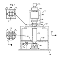
- Figure 1 schematically depicts a lithographic apparatus according to a particular embodiment of the invention.
- the apparatus comprises:
- the apparatus is of a transmissive type (e.g. employing a transmissive mask).
- the apparatus may be of a reflective type (e.g. employing a programmable mirror array of a type as referred to above).
- the illuminator IL receives a beam of radiation from a radiation source SO.
- the source and the lithographic apparatus may be separate entities, for example when the source is an excimer laser. In such cases, the source is not considered to form part of the lithographic apparatus and the radiation beam is passed from the source SO to the illuminator IL with the aid of a beam delivery system BD comprising for example suitable directing mirrors and/or a beam expander. In other cases the source may be integral part of the apparatus, for example when the source is a mercury lamp.
- the source SO and the illuminator IL, together with the beam delivery system BD if required, may be referred to as a radiation system.
- the illuminator IL may comprise adjusting means AM for adjusting the angular intensity distribution of the beam.
- adjusting means AM for adjusting the angular intensity distribution of the beam.
- the illuminator IL generally comprises various other components, such as an integrator IN and a condenser CO.
- the illuminator provides a conditioned beam of radiation, referred to as the projection beam PB, having a desired uniformity and intensity distribution in its cross-section.
- the projection beam PB is incident on the mask MA, which is held on the mask table MT. Having traversed the mask MA, the projection beam PB passes through the lens PL, which focuses the beam onto a target portion C of the substrate W.
- the substrate table WT can be moved accurately, e.g. so as to position different target portions C in the path of the beam PB.
- the first positioning means PM and another position sensor can be used to accurately position the mask MA with respect to the path of the beam PB, e.g. after mechanical retrieval from a mask library, or during a scan.
- the mask table MT may be connected to a short stroke actuator only, or may be fixed.
- Mask MA and substrate W may be aligned using mask alignment marks M1, M2 and substrate alignment marks P1, P2.
- the present invention concerns measures which can be taken to reduce the disturbance forces introduced by the supply of liquid between the final element of the projection system and the substrate in immersion lithography.
- the present invention is applicable to any type of liquid supply system, in particular localized area liquid supply systems which supply liquid to only a localized area of the substrate (c.f. a bath in which the substrate and perhaps substrate table are immersed).
- Figures 2 and 3 illustrate a first type of liquid supply system in which the liquid supply system is supported in the Z direction by a base frame BF or a metrology reference frame RF (which is supported by but isolated from the base frame).
- Figure 4 illustrates a liquid supply system using a barrier member which has an orifice in which the final element of the projection system PL is situated.
- the barrier member at least partly surrounds the final element of the projection system PL and forms a space for immersion liquid between the final element of the projection system and the substrate W.
- This type of liquid confinement system can either have its weight supported by the projection lens PL, by the base frame BF or any other frame or may support its weight through a hydro-static, hydro-dynamic or air bearing on the substrate W.
- a further generic type of liquid confinement system comprises a barrier member which at least partly surrounds the bottom of the projection lens and forms a space, defined by the substrate, the barrier member and the final element of the projection system PL, to which liquid is supplied.
- a liquid supply system is disclosed in, for example, European Patent application No. 03257070.7 , corresponding to published European Patent Application EP 1 420 298 A , and 03256643.2
- the barrier member has a gas bearing on its under side which is used to support the weight of the barrier member on the substrate W.
- the barrier member is connected to the base frame BF but only substantially to prevent movement in the XY plane.
- a similar barrier member may be used in which hydrostatic pressure is used to support the barrier member on the substrate W.
- the materials of which the above mentioned liquid supply systems are constructed, and in particular the barrier members, are chosen so that they have no adverse effects on contact with the immersion liquid (e.g. corrosion), they do not deteriorate the quality of the immersion liquid e.g. by dissolving in the immersion liquid, and they are compatible with all other requirements related to lithography that are not specific to immersion.
- Typical examples include austenitic stainless steels (e.g. the AISI 300 series and equivalents), nickel and nickel-based alloys, cobalt and cobalt-based alloys, chromium and chromium-based alloys, titanium and titanium-based alloys.
- austenitic stainless steels e.g. the AISI 300 series and equivalents
- nickel and nickel-based alloys e.g. the AISI 300 series and equivalents
- cobalt and cobalt-based alloys chromium and chromium-based alloys
- titanium and titanium-based alloys e.g. the AISI 300 series and equivalents
- Polymers may also be used and suitable polymers include many fluorine-based polymers (e.g. PTFE (Teflon (RTM)), PFA and PVDF) also, uncolored PE and PP could be used as well as all ceramic materials, with the exception of aluminum nitride.
- Ceramic-based composite materials may also be suitable as may be glasses (e.g. fused silica or quartz glass) and low thermal expansion glasses or glass ceramics (e.g. ULE (TM) from Coming or Zerodur (TM) from Schott).
- the present invention relates to all of the above mentioned liquid supply systems and reduces the disturbance forces which are transmitted to the substrate by the liquid supply system.
- Disturbance forces which might be transmitted to the substrate include forces due to gravity (for those liquid supply systems which are at least in part supported by the substrate) and the effect of immersion liquid pressure on the substrate W (for all types of liquid supply system).
- Other disturbance forces are, for example, from gas bearings or gas seals on the underside of a barrier member or due to activated movements in the z, Rz, Rx and Ry directions of the liquid supply system.
- the gas bearing or seal removes liquid and gas from the liquid supply system.
- the pressure of the liquid and/or gas can vary and cause disturbance forces to be transmitted to the substrate table.
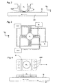
- the substrate table WT assembly is illustrated in Figure 5 . What is illustrated in Figure 5 is an example only and the substrate table WT may have a different construction. The principals explained in relation to Figure 5 (and Figures 6 and 7 ) are equally applicable to other types of substrate table WT as well as, of course, other types of liquid supply system.
- a liquid supply system with a barrier member 10 is illustrated.
- a gas seal 15 seals between the bottom of the barrier member 10 and the substrate W.
- the barrier member 10 provides a space 5 which can be filled with immersion liquid so that the space between the final element of the projection system PL, the substrate W and bounded by the barrier member 10 is filled with immersion liquid.
- the apparatus includes a compensation controller for controlling at least one actuator 45 to apply a compensating force on the substrate W substantially equal in magnitude and opposite in direction to force applied to the substrate by the liquid supply system.
- the substrate table WT is comprised of two main parts 40, 60.
- the upper main part 40 is designed for accurate fine positioning of the substrate W, which is carried by the upper main part 40.
- the lower main part 60 is moved by positioning means 65 on a course scale, final accurate positioning being achieved by movement of the upper main part 40 by actuators 45 which act between the upper and lower main parts 40, 60.
- the present invention is described below by referring to actuators 45 between the main upper and lower parts of the substrate table 40, 60 but of course is equally applicable to other substrate tables for example those types that only have one part or indeed those types that have more than two parts.
- the invention is described in relation to actuators 45 being the main fine three dimensional positioning actuators though the invention may be performed with separate actuators specifically for applying the compensating forces required. These compensating forces may even be applied directly to the substrate W or could indeed be applied by the actuator means 65 for the main lower part of the substrate table WT.
- Both sets of actuators 45, 65 are capable of moving their respective parts of the substrate table 40, 60 in the XY plane and, to a more limited extent, in the Z direction relative to the lower main part 60 and to the base frame BF respectively.
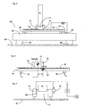
- Figure 6 illustrates how the present invention uses the compensation controller 30 for calculating the necessary compensation force and for controlling the actuator 45 to compensate for the effect of gravity of the barrier member 10 on the substrate W in the case where the barrier member 10 is supported by the substrate W (for example through a hydrostatic, hydrodynamic or air bearing).
- the calculations preferably account for Rx, Ry and Rz rotational movements as well as z movements.
- the same principals can be applied to other types of liquid supply system when considering the effects of disturbance forces transmitted through the immersion liquid and which will be described in more detail in relation to Figure 7 .
- Figure 6 illustrates the real life 3-dimensional problem in two dimensions.
- the weight of the barrier member 10 is constant, as can be seen from Figure 6 , when the center of the substrate W moves away from directly underneath the optical axis of the projection system (indicated as dotted line 1) a moment 100 around the center of gravity of the upper part of the substrate table 40 is generated. In the case illustrated in Figure 6 this requires a larger compensating force F 1 to be applied on the left hand actuator 45 than the compensating force F 2 applied to the right hand actuator 45.
- the actuators 45 must apply a force to support both the upper part 40 of the substrate table and the barrier member. If the substrate table WT were moved to the right, the force on the left hand actuator F 1 would increase and the force on the right hand actuator F 2 would need to reduce.
- the compensation controller can calculate the compensating force based on a desired position of the substrate W and control the actuator 45 accordingly.
- the calculation can also be carried out using the actual x, y position as this is usually only a few nm different to the desired position.
- the actuators are controlled to apply compensating force on the substrate table substantially equal in magnitude and opposite in direction to the force applied to the substrate by the liquid supply system.
- liquid supply system applies forces to the substrate table WT directly and not through the substrate.
- the compensation controller can compensate for any disturbances caused in this way.
- the compensation controller 30 can calculate the compensation force in a feed-forward manner by being fed the desired (or actual) co-ordinates of the substrate W. From this information the combined center of gravity of the upper part of the substrate table 40 and of the barrier member 10 can be calculated from a knowledge of their positions and masses and the force applied to actuator 45 as appropriate. Clearly the calculations can be based on any point in space. The calculations can be carried out from a knowledge of the mass of the barrier member 10 and its position as well as the mass of the upper part 40 of the substrate table, including the substrate W.
- the compensation controller 30 can additionally or alternatively calculate the compensation force required due to pressure of the liquid and/or gas in the gas seal or pressure of liquid in the space.
- the pressures can be measured and the calculation performed in a feed forward or feed back manner.
- a pressure sensor 80 is provided or the data from the force sensor 70 can be used.
- the pressure can be calculated from, for example, a knowledge of the flow rate of liquid into and/or out of the space 5. In this way the inherent variations in pressure of the immersion liquid in the space 5 due to extraction of air/water mixture can be compensated.
- a compensation force component is added to the overall force signal generated for each of the actuators 45.
- the other components include that for positioning of the substrate W as well as that for compensating the force of gravity on the upper part 40.
- the barrier member 10 is partly supported by another part of the apparatus other than the substrate or substrate table, and is actuated in the Z direction by an actuator 70, it is possible to measure the force on the substrate W from a knowledge of the force applied by the actuator 70.
- the actuator 70 may be a electromagnetic motor, a piezoelectric motor, an air bearing between the barrier member 10 and the substrate W or a hydrostatic or hydrodynamic bearing or any other sort of actuator. Information about the forces applied by the actuators can be used to calculate the force on the substrate W and used (in a feed-forward manner) to calculate the compensation force required.
- the element 70 may be a force sensor 70 which outputs a signal representing the force between the barrier member and the projection lens which can be used by the compensation controller to calculate the required compensation force.
- the compensation force may be filtered (and thereby corrected) for certain dynamic properties of the barrier member 10 (such as bending for example) and possible bearing characteristics (such as elasticity).
- the compensation controller may also calculate the compensation force in a feedback manner based on any variable other than the position of the table.
- the feedback calculation may be on the basis of the force sensor 70 output or the actuator force or the pressure of the liquid in the space and/or at the seal and/or the gas pressure at the seal.
- the pressure of liquid in space 5 and the gas seal can apply a force (pressure times area) to the substrate W or substrate table WT.
- the moment applied to the upper part of the substrate table 40 by the immersion liquid is also positionally dependent and the force can be calculated from a knowledge of the pressure of immersion liquid in the space 5 and the surface area over which that pressure is applied.
Landscapes
- Physics & Mathematics (AREA)
- General Physics & Mathematics (AREA)
- Engineering & Computer Science (AREA)
- Computer Networks & Wireless Communication (AREA)
- Health & Medical Sciences (AREA)
- Environmental & Geological Engineering (AREA)
- Epidemiology (AREA)
- Public Health (AREA)
- Exposure And Positioning Against Photoresist Photosensitive Materials (AREA)
- Exposure Of Semiconductors, Excluding Electron Or Ion Beam Exposure (AREA)
Claims (23)
- Ein lithographisches Gerät, das Folgendes beinhaltet:- ein Beleuchtungssystem (IL) zum Bereitstellen eines Projektionsstrahls (PB) aus Strahlung;- eine Stützstruktur (MT) zum Stützen von Musteraufbringungsmitteln (MA), wobei die Musteraufbringungsmittel dazu dienen, den Projektionsstrahl in seinem Querschnitt mit einem Muster zu versehen;- einen Substrattisch (WT) zum Halten eines Substrats (W);- ein Projektionssystem (PL) zum Projizieren des gemusterten Strahls auf einen Zielabschnitt des Substrats,- ein Flüssigkeitszufuhrsystem zum Bereitstellen einer Immersionsflüssigkeit zwischen einem letzten Element des Projektionssystems und dem Substrat und- mindestens einen Aktor (45; 65) zum Anwenden einer Kraft auf das Substrat;dadurch gekennzeichnet, dass es ferner Folgendes beinhaltet:- eine Kompensationssteuerung (30), die eingerichtet ist, um eine kompensierende Kraft, die von dem mindestens einen Aktor auf das Substrat angewendet werden soll, zu berechnen, wobei die kompensierende Kraft im Wesentlichen von gleicher Stärke wie eine von dem Flüssigkeitszufuhrsystem auf das Substrat angewendete Kraft und ihr in der Richtung entgegengesetzt ist.
- Gerät gemäß Anspruch 1, wobei die Kompensationssteuerung die Kompensationskraft vorwärtskoppelnd berechnet.
- Gerät gemäß Anspruch 1, wobei die Kompensationssteuerung die Kompensationskraft rückkoppelnd berechnet.
- Gerät gemäß Anspruch 1, wobei die Kompensationssteuerung eine Kompensationskraft berechnet, die gefiltert und dynamischen Eigenschaften des Flüssigkeitszufuhrsystems entsprechend korrigiert ist.
- Gerät gemäß Anspruch 1, wobei die Kompensationssteuerung die Kompensationskraft auf der Grundlage einer tatsächlichen oder einer gewünschten Position des Substrats berechnet.
- Gerät gemäß Anspruch 1, wobei die Kompensationssteuerung den mindestens einen Aktor steuert, um eine kompensierende Kraft auf den Substrattisch anzuwenden, die im Wesentlichen von gleicher Stärke wie eine von dem Flüssigkeitszufuhrsystem auf den Substratstisch angewendete Kraft und ihr in der Richtung entgegengesetzt ist.
- Gerät gemäß Anspruch 1, wobei die Kompensationssteuerung die Kompensationskraft auf der Grundlage einer Kraft, die von dem Flüssigkeitszufuhrsystem aufgrund der Schwerkraft auf das Substrat angewendet wird, berechnet.
- Gerät gemäß Anspruch 1, wobei das Flüssigkeitszufuhrsystem ein Absperrungsteil (10) beinhaltet, das das letzte Element des Projektionssystems mindestens teilweise umgibt, wodurch zwischen dem letzten Element des Projektionssystems und dem Substrat ein Raum (5) definiert wird, um mindestens teilweise mit Immersionsflüssigkeit gefüllt zu werden.
- Gerät gemäß Anspruch 8, wobei das Absperrungsteil mindestens teilweise von dem Substrat und/oder dem Substrattisch gestützt wird.
- Gerät gemäß Anspruch 8, wobei das Absperrungsteil unter Verwendung eines Absperrungsaktors (70) in einer Richtung, die zu der optischen Achse des Projektionssystems parallel ist, positioniert wird.
- Gerät gemäß Anspruch 10, wobei der Absperrungsaktor ein Luftlager, ein hydrodynamisches Lager oder ein hydrostatisches Lager ist.
- Gerät gemäß Anspruch 10, wobei die Kompensationssteuerung die kompensierende Kraft auf der Grundlage der Kraft, die von dem Absperrungsaktor benötigt wird, um das Absperrungsteil still zu halten, berechnet.
- Gerät gemäß Anspruch 1, wobei die Kompensationssteuerung die kompensierende Kraft auf der Grundlage von Druckschwankungen der Immersionsflüssigkeit oder Druckschwankungen von Flüssigkeit und/oder Gas in einem Gaslager des Flüssigkeitszufuhrsystems berechnet.
- Gerät gemäß Anspruch 13, das ferner einen Drucksensor (80) zum Messen des Drucks der Immersionsflüssigkeit und/oder einen Kraftsensor zum Messen einer Kraft zwischen dem Flüssigkeitszufuhrsystem und dem Projektionssystem beinhaltet.
- Gerät gemäß Anspruch 1, wobei der Aktor zum Anwenden einer Kraft auf mindestens einen Teil des Substrattischs, der das Substrat stützt, dient.
- Gerät gemäß Anspruch 15, wobei die Kompensationssteuerung die kompensierende Kraft auf der Grundlage der gewünschten oder tatsächlichen Position des Schwerpunktes des Teils des Substrattisches, der das Substrat stützt, relativ zum Projektionssystem berechnet.
- Gerät gemäß Anspruch 1, wobei die Kompensationssteuerung dazu dient, in der Richtung der optischen Achse des Projektionssystems und drehweise um zu der optischen Achse des Projektionssystems senkrechte Achsen eine kompensierende Kraft auf das Substrat anzuwenden.
- Ein Verfahren zur Herstellung einer Vorrichtung, das Folgendes beinhaltet:- Bereitstellen eines Substrats (W);- Bereitstellen eines Projektionsstrahls (PB) aus Strahlung unter Verwendung eines Beleuchtungssystems (IL);- Verwenden von Musteraufbringungsmitteln (MA), um den Projektionsstrahl in seinem Querschnitt mit einem Muster zu versehen;- Projizieren des gemusterten Strahls aus Strahlung auf einen Zielabschnitt des Substrats unter Verwendung eines Projektionssystems (PL);- Bereitstellen einer Immersionsflüssigkeit zwischen einem letzten Element des Projektionssystems und dem Substrat und- Berechnen und Anwenden einer kompensierenden Kraft auf das Substrat, die im Wesentlichen von gleicher Stärke wie eine von dem Flüssigkeitszufuhrsystem auf das Substrat angewendete Kraft und ihr in der Richtung entgegengesetzt ist.
- Verfahren gemäß Anspruch 18, wobei die Kompensationskraft vorwärtskoppelnd berechnet wird.
- Verfahren gemäß Anspruch 18, wobei die Kompensationskraft rückkoppelnd berechnet wird.
- Verfahren gemäß Anspruch 18, wobei die Kompensationskraft auf der Grundlage der tatsächlichen oder einer gewünschten Position des Substrats berechnet wird.
- Verfahren gemäß Anspruch 18, wobei die Kompensationskraft auf der Grundlage einer Kraft, die von dem Flüssigkeitszufuhrsystem aufgrund der Schwerkraft auf das Substrat angewendet wird, berechnet wird.
- Verfahren gemäß Anspruch 18, wobei die kompensierende Kraft auf der Grundlage von Druckschwankungen der Immersionsflüssigkeit berechnet wird.
Applications Claiming Priority (2)
| Application Number | Priority Date | Filing Date | Title |
|---|---|---|---|
| US816189 | 2004-04-02 | ||
| US10/816,189 US7295283B2 (en) | 2004-04-02 | 2004-04-02 | Lithographic apparatus and device manufacturing method |
Publications (2)
| Publication Number | Publication Date |
|---|---|
| EP1582929A1 EP1582929A1 (de) | 2005-10-05 |
| EP1582929B1 true EP1582929B1 (de) | 2010-05-12 |
Family
ID=34887757
Family Applications (1)
| Application Number | Title | Priority Date | Filing Date |
|---|---|---|---|
| EP05251708A Ceased EP1582929B1 (de) | 2004-04-02 | 2005-03-21 | Lithographischer Apparat und Verfahren zur Herstellung einer Vorrichtung |
Country Status (8)
| Country | Link |
|---|---|
| US (1) | US7295283B2 (de) |
| EP (1) | EP1582929B1 (de) |
| JP (1) | JP4108087B2 (de) |
| KR (1) | KR100660505B1 (de) |
| CN (1) | CN100451836C (de) |
| DE (1) | DE602005021180D1 (de) |
| SG (1) | SG115816A1 (de) |
| TW (1) | TWI267707B (de) |
Families Citing this family (83)
| Publication number | Priority date | Publication date | Assignee | Title |
|---|---|---|---|---|
| US9482966B2 (en) | 2002-11-12 | 2016-11-01 | Asml Netherlands B.V. | Lithographic apparatus and device manufacturing method |
| SG121819A1 (en) | 2002-11-12 | 2006-05-26 | Asml Netherlands Bv | Lithographic apparatus and device manufacturing method |
| US10503084B2 (en) | 2002-11-12 | 2019-12-10 | Asml Netherlands B.V. | Lithographic apparatus and device manufacturing method |
| DE10261775A1 (de) | 2002-12-20 | 2004-07-01 | Carl Zeiss Smt Ag | Vorrichtung zur optischen Vermessung eines Abbildungssystems |
| KR101643112B1 (ko) | 2003-02-26 | 2016-07-26 | 가부시키가이샤 니콘 | 노광 장치, 노광 방법 및 디바이스 제조 방법 |
| JP4902201B2 (ja) * | 2003-04-07 | 2012-03-21 | 株式会社ニコン | 露光装置、露光方法及びデバイス製造方法 |
| JP4656057B2 (ja) * | 2003-04-10 | 2011-03-23 | 株式会社ニコン | 液浸リソグラフィ装置用電気浸透素子 |
| KR101431938B1 (ko) | 2003-04-10 | 2014-08-19 | 가부시키가이샤 니콘 | 액침 리소그래피 장치용 운반 영역을 포함하는 환경 시스템 |
| SG141426A1 (en) | 2003-04-10 | 2008-04-28 | Nikon Corp | Environmental system including vacuum scavange for an immersion lithography apparatus |
| SG139733A1 (en) | 2003-04-11 | 2008-02-29 | Nikon Corp | Apparatus having an immersion fluid system configured to maintain immersion fluid in a gap adjacent an optical assembly |
| KR101289959B1 (ko) * | 2003-04-11 | 2013-07-26 | 가부시키가이샤 니콘 | 액침 리소그래피에 의한 광학기기의 세정방법 |
| KR20050122269A (ko) * | 2003-04-17 | 2005-12-28 | 가부시키가이샤 니콘 | 액침 리소그래피를 이용하기 위한 오토포커스 소자의광학적 배열 |
| TWI295414B (en) | 2003-05-13 | 2008-04-01 | Asml Netherlands Bv | Lithographic apparatus and device manufacturing method |
| WO2004102646A1 (ja) * | 2003-05-15 | 2004-11-25 | Nikon Corporation | 露光装置及びデバイス製造方法 |
| TW201515064A (zh) | 2003-05-23 | 2015-04-16 | 尼康股份有限公司 | 曝光方法及曝光裝置以及元件製造方法 |
| TWI474380B (zh) | 2003-05-23 | 2015-02-21 | 尼康股份有限公司 | A method of manufacturing an exposure apparatus and an element |
| WO2004107417A1 (ja) | 2003-05-28 | 2004-12-09 | Nikon Corporation | 露光方法及び露光装置、並びにデバイス製造方法 |
| US7213963B2 (en) | 2003-06-09 | 2007-05-08 | Asml Netherlands B.V. | Lithographic apparatus and device manufacturing method |
| EP1486827B1 (de) | 2003-06-11 | 2011-11-02 | ASML Netherlands B.V. | Lithographischer Apparat und Verfahren zur Herstellung einer Vorrichtung |
| EP3104396B1 (de) | 2003-06-13 | 2018-03-21 | Nikon Corporation | Belichtungsverfahren, substrattisch, belichtungsvorrichtung und vorrichtungsherstellungsverfahren |
| KR101476087B1 (ko) | 2003-06-19 | 2014-12-23 | 가부시키가이샤 니콘 | 노광 장치 및 디바이스 제조방법 |
| WO2005006026A2 (en) * | 2003-07-01 | 2005-01-20 | Nikon Corporation | Using isotopically specified fluids as optical elements |
| EP2843472B1 (de) * | 2003-07-08 | 2016-12-07 | Nikon Corporation | Waferplatte für die Immersionslithografie |
| WO2005006418A1 (ja) * | 2003-07-09 | 2005-01-20 | Nikon Corporation | 露光装置及びデバイス製造方法 |
| EP2264531B1 (de) | 2003-07-09 | 2013-01-16 | Nikon Corporation | Belichtungsgerät und Verfahren zur Herstellung einer Vorrichtung |
| EP1643543B1 (de) * | 2003-07-09 | 2010-11-24 | Nikon Corporation | Belichtungsvorrichtung und verfahren zur bauelementherstellung |
| JP4524669B2 (ja) * | 2003-07-25 | 2010-08-18 | 株式会社ニコン | 投影光学系の検査方法および検査装置 |
| KR20190002749A (ko) | 2003-07-28 | 2019-01-08 | 가부시키가이샤 니콘 | 노광 장치 및 디바이스 제조 방법, 그리고 노광 장치의 제어 방법 |
| EP1503244A1 (de) | 2003-07-28 | 2005-02-02 | ASML Netherlands B.V. | Lithographischer Projektionsapparat und Verfahren zur Herstellung einer Vorrichtung |
| US7779781B2 (en) | 2003-07-31 | 2010-08-24 | Asml Netherlands B.V. | Lithographic apparatus and device manufacturing method |
| TWI263859B (en) | 2003-08-29 | 2006-10-11 | Asml Netherlands Bv | Lithographic apparatus and device manufacturing method |
| KR101419192B1 (ko) * | 2003-08-29 | 2014-07-15 | 가부시키가이샤 니콘 | 노광 장치 및 디바이스 제조 방법 |
| EP1660925B1 (de) | 2003-09-03 | 2015-04-29 | Nikon Corporation | Vorrichtung und verfahren zur bereitstellung eines fluids für die immersionslithographie |
| JP4444920B2 (ja) * | 2003-09-19 | 2010-03-31 | 株式会社ニコン | 露光装置及びデバイス製造方法 |
| KR101498437B1 (ko) | 2003-09-29 | 2015-03-03 | 가부시키가이샤 니콘 | 노광장치, 노광방법 및 디바이스 제조방법 |
| KR20060126949A (ko) | 2003-10-08 | 2006-12-11 | 가부시키가이샤 니콘 | 기판 반송 장치와 기판 반송 방법, 노광 장치와 노광 방법,및 디바이스 제조 방법 |
| EP1672681B8 (de) | 2003-10-08 | 2011-09-21 | Miyagi Nikon Precision Co., Ltd. | Belichtungsgerät, substrattrageverfahren, belichtungsverfahren und verfahren zur herstellung einer vorrichtung |
| JP2005136364A (ja) * | 2003-10-08 | 2005-05-26 | Zao Nikon Co Ltd | 基板搬送装置、露光装置、並びにデバイス製造方法 |
| TW200514138A (en) | 2003-10-09 | 2005-04-16 | Nippon Kogaku Kk | Exposure equipment and exposure method, manufacture method of component |
| US7411653B2 (en) | 2003-10-28 | 2008-08-12 | Asml Netherlands B.V. | Lithographic apparatus |
| EP3370115A1 (de) | 2003-12-03 | 2018-09-05 | Nikon Corporation | Belichtungsvorrichtung, belichtungsverfahren, und verfahren zur herstellung eines artikels |
| JPWO2005057635A1 (ja) * | 2003-12-15 | 2007-07-05 | 株式会社ニコン | 投影露光装置及びステージ装置、並びに露光方法 |
| US20070081133A1 (en) * | 2004-12-14 | 2007-04-12 | Niikon Corporation | Projection exposure apparatus and stage unit, and exposure method |
| KR101281397B1 (ko) | 2003-12-15 | 2013-07-02 | 가부시키가이샤 니콘 | 스테이지 장치, 노광 장치, 및 노광 방법 |
| KR101440743B1 (ko) | 2004-01-05 | 2014-09-17 | 가부시키가이샤 니콘 | 노광 장치, 노광 방법 및 디바이스 제조 방법 |
| US7589822B2 (en) | 2004-02-02 | 2009-09-15 | Nikon Corporation | Stage drive method and stage unit, exposure apparatus, and device manufacturing method |
| JP4506674B2 (ja) | 2004-02-03 | 2010-07-21 | 株式会社ニコン | 露光装置及びデバイス製造方法 |
| KR101250155B1 (ko) * | 2004-03-25 | 2013-04-05 | 가부시키가이샤 니콘 | 노광 장치 및 디바이스 제조 방법 |
| EP1747499A2 (de) * | 2004-05-04 | 2007-01-31 | Nikon Corporation | Vorrichtung und verfahren zur bereitstellung eines fluids für die immersionslithographie |
| US7616383B2 (en) | 2004-05-18 | 2009-11-10 | Asml Netherlands B.V. | Lithographic apparatus and device manufacturing method |
| US7486381B2 (en) * | 2004-05-21 | 2009-02-03 | Asml Netherlands B.V. | Lithographic apparatus and device manufacturing method |
| CN100594430C (zh) | 2004-06-04 | 2010-03-17 | 卡尔蔡司Smt股份公司 | 用于测量光学成像系统的图像质量的系统 |
| KR101421915B1 (ko) | 2004-06-09 | 2014-07-22 | 가부시키가이샤 니콘 | 노광 장치 및 디바이스 제조 방법 |
| EP2624282B1 (de) * | 2004-06-10 | 2017-02-08 | Nikon Corporation | Immersionsbelichtungsvorrichtung und -verfahren, und Verfahren zur Herstellung eines Geräts |
| JP4623095B2 (ja) * | 2004-06-17 | 2011-02-02 | 株式会社ニコン | 液浸リソグラフィレンズの流体圧力補正 |
| EP1761822A4 (de) * | 2004-07-01 | 2009-09-09 | Nikon Corp | Dynamisches fluidregelsystem für die immersionslithographie |
| US7463330B2 (en) | 2004-07-07 | 2008-12-09 | Asml Netherlands B.V. | Lithographic apparatus and device manufacturing method |
| EP1780772B1 (de) | 2004-07-12 | 2009-09-02 | Nikon Corporation | Belichtungsgerät und bauelemente-herstellungsverfahren |
| JP3870207B2 (ja) | 2004-08-05 | 2007-01-17 | キヤノン株式会社 | 液浸露光装置及びデバイス製造方法 |
| US8305553B2 (en) * | 2004-08-18 | 2012-11-06 | Nikon Corporation | Exposure apparatus and device manufacturing method |
| US7701550B2 (en) | 2004-08-19 | 2010-04-20 | Asml Netherlands B.V. | Lithographic apparatus and device manufacturing method |
| US7355674B2 (en) * | 2004-09-28 | 2008-04-08 | Asml Netherlands B.V. | Lithographic apparatus, device manufacturing method and computer program product |
| US7119876B2 (en) * | 2004-10-18 | 2006-10-10 | Asml Netherlands B.V. | Lithographic apparatus and device manufacturing method |
| US7397533B2 (en) | 2004-12-07 | 2008-07-08 | Asml Netherlands B.V. | Lithographic apparatus and device manufacturing method |
| US7880860B2 (en) | 2004-12-20 | 2011-02-01 | Asml Netherlands B.V. | Lithographic apparatus and device manufacturing method |
| US8692973B2 (en) | 2005-01-31 | 2014-04-08 | Nikon Corporation | Exposure apparatus and method for producing device |
| KR20180125636A (ko) | 2005-01-31 | 2018-11-23 | 가부시키가이샤 니콘 | 노광 장치 및 디바이스 제조 방법 |
| US7282701B2 (en) | 2005-02-28 | 2007-10-16 | Asml Netherlands B.V. | Sensor for use in a lithographic apparatus |
| USRE43576E1 (en) | 2005-04-08 | 2012-08-14 | Asml Netherlands B.V. | Dual stage lithographic apparatus and device manufacturing method |
| KR100802008B1 (ko) * | 2005-09-13 | 2008-02-12 | 타이완 세미콘덕터 매뉴팩쳐링 컴퍼니 리미티드 | 이머션 리소그래피 장치 및 방법 |
| US7357768B2 (en) * | 2005-09-22 | 2008-04-15 | William Marshall | Recliner exerciser |
| US7773195B2 (en) | 2005-11-29 | 2010-08-10 | Asml Holding N.V. | System and method to increase surface tension and contact angle in immersion lithography |
| US7649611B2 (en) | 2005-12-30 | 2010-01-19 | Asml Netherlands B.V. | Lithographic apparatus and device manufacturing method |
| US7443483B2 (en) * | 2006-08-11 | 2008-10-28 | Entegris, Inc. | Systems and methods for fluid flow control in an immersion lithography system |
| US8654305B2 (en) | 2007-02-15 | 2014-02-18 | Asml Holding N.V. | Systems and methods for insitu lens cleaning in immersion lithography |
| US8817226B2 (en) | 2007-02-15 | 2014-08-26 | Asml Holding N.V. | Systems and methods for insitu lens cleaning using ozone in immersion lithography |
| US20080198348A1 (en) * | 2007-02-20 | 2008-08-21 | Nikon Corporation | Apparatus and methods for minimizing force variation from immersion liquid in lithography systems |
| KR101448152B1 (ko) * | 2008-03-26 | 2014-10-07 | 삼성전자주식회사 | 수직 포토게이트를 구비한 거리측정 센서 및 그를 구비한입체 컬러 이미지 센서 |
| US9176393B2 (en) | 2008-05-28 | 2015-11-03 | Asml Netherlands B.V. | Lithographic apparatus and a method of operating the apparatus |
| NL2004547A (en) * | 2009-05-14 | 2010-11-18 | Asml Netherlands Bv | An immersion lithographic apparatus and a device manufacturing method. |
| US8619231B2 (en) * | 2009-05-21 | 2013-12-31 | Nikon Corporation | Cleaning method, exposure method, and device manufacturing method |
| NL2008695A (en) * | 2011-05-25 | 2012-11-27 | Asml Netherlands Bv | Lithographic apparatus comprising substrate table. |
| US11879683B2 (en) * | 2020-04-07 | 2024-01-23 | Kla Corporation | Self-aligning vacuum feed-through for liquid nitrogen |
Family Cites Families (69)
| Publication number | Priority date | Publication date | Assignee | Title |
|---|---|---|---|---|
| DE242880C (de) | ||||
| DE224448C (de) | ||||
| DE221563C (de) | ||||
| DE206607C (de) | ||||
| GB1242527A (en) * | 1967-10-20 | 1971-08-11 | Kodak Ltd | Optical instruments |
| US3573975A (en) * | 1968-07-10 | 1971-04-06 | Ibm | Photochemical fabrication process |
| ATE1462T1 (de) | 1979-07-27 | 1982-08-15 | Werner W. Dr. Tabarelli | Optisches lithographieverfahren und einrichtung zum kopieren eines musters auf eine halbleiterscheibe. |
| FR2474708B1 (fr) | 1980-01-24 | 1987-02-20 | Dme | Procede de microphotolithographie a haute resolution de traits |
| JPS5754317A (en) * | 1980-09-19 | 1982-03-31 | Hitachi Ltd | Method and device for forming pattern |
| US4509852A (en) * | 1980-10-06 | 1985-04-09 | Werner Tabarelli | Apparatus for the photolithographic manufacture of integrated circuit elements |
| US4346164A (en) * | 1980-10-06 | 1982-08-24 | Werner Tabarelli | Photolithographic method for the manufacture of integrated circuits |
| US4390273A (en) * | 1981-02-17 | 1983-06-28 | Censor Patent-Und Versuchsanstalt | Projection mask as well as a method and apparatus for the embedding thereof and projection printing system |
| JPS57153433A (en) * | 1981-03-18 | 1982-09-22 | Hitachi Ltd | Manufacturing device for semiconductor |
| JPS58202448A (ja) | 1982-05-21 | 1983-11-25 | Hitachi Ltd | 露光装置 |
| JPS6265326A (ja) | 1985-09-18 | 1987-03-24 | Hitachi Ltd | 露光装置 |
| JPS62121417A (ja) | 1985-11-22 | 1987-06-02 | Hitachi Ltd | 液浸対物レンズ装置 |
| JPS63157419A (ja) | 1986-12-22 | 1988-06-30 | Toshiba Corp | 微細パタ−ン転写装置 |
| US5040020A (en) * | 1988-03-31 | 1991-08-13 | Cornell Research Foundation, Inc. | Self-aligned, high resolution resonant dielectric lithography |
| JPH03209479A (ja) | 1989-09-06 | 1991-09-12 | Sanee Giken Kk | 露光方法 |
| US5121256A (en) * | 1991-03-14 | 1992-06-09 | The Board Of Trustees Of The Leland Stanford Junior University | Lithography system employing a solid immersion lens |
| JPH04305917A (ja) | 1991-04-02 | 1992-10-28 | Nikon Corp | 密着型露光装置 |
| JPH04305915A (ja) | 1991-04-02 | 1992-10-28 | Nikon Corp | 密着型露光装置 |
| JPH06124873A (ja) | 1992-10-09 | 1994-05-06 | Canon Inc | 液浸式投影露光装置 |
| JP2753930B2 (ja) * | 1992-11-27 | 1998-05-20 | キヤノン株式会社 | 液浸式投影露光装置 |
| JP2520833B2 (ja) | 1992-12-21 | 1996-07-31 | 東京エレクトロン株式会社 | 浸漬式の液処理装置 |
| JPH07220990A (ja) | 1994-01-28 | 1995-08-18 | Hitachi Ltd | パターン形成方法及びその露光装置 |
| JPH08316124A (ja) * | 1995-05-19 | 1996-11-29 | Hitachi Ltd | 投影露光方法及び露光装置 |
| WO1998009278A1 (en) * | 1996-08-26 | 1998-03-05 | Digital Papyrus Technologies | Method and apparatus for coupling an optical lens to a disk through a coupling medium having a relatively high index of refraction |
| US5825043A (en) | 1996-10-07 | 1998-10-20 | Nikon Precision Inc. | Focusing and tilting adjustment system for lithography aligner, manufacturing apparatus or inspection apparatus |
| JP3612920B2 (ja) | 1997-02-14 | 2005-01-26 | ソニー株式会社 | 光学記録媒体の原盤作製用露光装置 |
| JPH10255319A (ja) | 1997-03-12 | 1998-09-25 | Hitachi Maxell Ltd | 原盤露光装置及び方法 |
| JP3747566B2 (ja) | 1997-04-23 | 2006-02-22 | 株式会社ニコン | 液浸型露光装置 |
| JP3817836B2 (ja) | 1997-06-10 | 2006-09-06 | 株式会社ニコン | 露光装置及びその製造方法並びに露光方法及びデバイス製造方法 |
| US5900354A (en) * | 1997-07-03 | 1999-05-04 | Batchelder; John Samuel | Method for optical inspection and lithography |
| JPH11176727A (ja) | 1997-12-11 | 1999-07-02 | Nikon Corp | 投影露光装置 |
| AU1505699A (en) | 1997-12-12 | 1999-07-05 | Nikon Corporation | Projection exposure method and projection aligner |
| WO1999049504A1 (fr) | 1998-03-26 | 1999-09-30 | Nikon Corporation | Procede et systeme d'exposition par projection |
| JP2000058436A (ja) | 1998-08-11 | 2000-02-25 | Nikon Corp | 投影露光装置及び露光方法 |
| TWI242111B (en) * | 1999-04-19 | 2005-10-21 | Asml Netherlands Bv | Gas bearings for use in vacuum chambers and their application in lithographic projection apparatus |
| JP4504479B2 (ja) | 1999-09-21 | 2010-07-14 | オリンパス株式会社 | 顕微鏡用液浸対物レンズ |
| JP2001272604A (ja) * | 2000-03-27 | 2001-10-05 | Olympus Optical Co Ltd | 液浸対物レンズおよびそれを用いた光学装置 |
| TW591653B (en) * | 2000-08-08 | 2004-06-11 | Koninkl Philips Electronics Nv | Method of manufacturing an optically scannable information carrier |
| KR100866818B1 (ko) * | 2000-12-11 | 2008-11-04 | 가부시키가이샤 니콘 | 투영광학계 및 이 투영광학계를 구비한 노광장치 |
| WO2002091078A1 (en) * | 2001-05-07 | 2002-11-14 | Massachusetts Institute Of Technology | Methods and apparatus employing an index matching medium |
| US6600547B2 (en) * | 2001-09-24 | 2003-07-29 | Nikon Corporation | Sliding seal |
| WO2003040830A2 (en) * | 2001-11-07 | 2003-05-15 | Applied Materials, Inc. | Optical spot grid array printer |
| DE10210899A1 (de) * | 2002-03-08 | 2003-09-18 | Zeiss Carl Smt Ag | Refraktives Projektionsobjektiv für Immersions-Lithographie |
| DE10229818A1 (de) * | 2002-06-28 | 2004-01-15 | Carl Zeiss Smt Ag | Verfahren zur Fokusdetektion und Abbildungssystem mit Fokusdetektionssystem |
| EP1357429A1 (de) * | 2002-04-23 | 2003-10-29 | ASML Netherlands B.V. | Lithographisches Gerät und Verfahren zur Herstellung einer Vorrichtung |
| KR20050035890A (ko) | 2002-08-23 | 2005-04-19 | 가부시키가이샤 니콘 | 투영 광학계, 포토리소그래피 방법, 노광 장치 및 그 이용방법 |
| US6788477B2 (en) * | 2002-10-22 | 2004-09-07 | Taiwan Semiconductor Manufacturing Co., Ltd. | Apparatus for method for immersion lithography |
| DE10258718A1 (de) * | 2002-12-09 | 2004-06-24 | Carl Zeiss Smt Ag | Projektionsobjektiv, insbesondere für die Mikrolithographie, sowie Verfahren zur Abstimmung eines Projektionsobjektives |
| KR20050085236A (ko) | 2002-12-10 | 2005-08-29 | 가부시키가이샤 니콘 | 노광 장치 및 디바이스 제조 방법 |
| DE10257766A1 (de) | 2002-12-10 | 2004-07-15 | Carl Zeiss Smt Ag | Verfahren zur Einstellung einer gewünschten optischen Eigenschaft eines Projektionsobjektivs sowie mikrolithografische Projektionsbelichtungsanlage |
| JP4232449B2 (ja) | 2002-12-10 | 2009-03-04 | 株式会社ニコン | 露光方法、露光装置、及びデバイス製造方法 |
| WO2004053954A1 (ja) | 2002-12-10 | 2004-06-24 | Nikon Corporation | 露光装置及びデバイス製造方法 |
| WO2004053952A1 (ja) | 2002-12-10 | 2004-06-24 | Nikon Corporation | 露光装置及びデバイス製造方法 |
| EP1571697A4 (de) | 2002-12-10 | 2007-07-04 | Nikon Corp | Belichtungssystem und bauelementeherstellungsverfahren |
| AU2003302831A1 (en) | 2002-12-10 | 2004-06-30 | Nikon Corporation | Exposure method, exposure apparatus and method for manufacturing device |
| SG157962A1 (en) | 2002-12-10 | 2010-01-29 | Nikon Corp | Exposure apparatus and method for producing device |
| US6992750B2 (en) * | 2002-12-10 | 2006-01-31 | Canon Kabushiki Kaisha | Exposure apparatus and method |
| KR101101737B1 (ko) | 2002-12-10 | 2012-01-05 | 가부시키가이샤 니콘 | 노광장치 및 노광방법, 디바이스 제조방법 |
| KR20050085026A (ko) | 2002-12-10 | 2005-08-29 | 가부시키가이샤 니콘 | 광학 소자 및 그 광학 소자를 사용한 투영 노광 장치 |
| JP4352874B2 (ja) | 2002-12-10 | 2009-10-28 | 株式会社ニコン | 露光装置及びデバイス製造方法 |
| WO2004053957A1 (ja) | 2002-12-10 | 2004-06-24 | Nikon Corporation | 面位置検出装置、露光方法、及びデバイス製造方法 |
| CN100370533C (zh) | 2002-12-13 | 2008-02-20 | 皇家飞利浦电子股份有限公司 | 用于照射层的方法和用于将辐射导向层的装置 |
| ATE365962T1 (de) | 2002-12-19 | 2007-07-15 | Koninkl Philips Electronics Nv | Verfahren und anordnung zum bestrahlen einer schicht mittels eines lichtpunkts |
| EP1584089B1 (de) | 2002-12-19 | 2006-08-02 | Koninklijke Philips Electronics N.V. | Verfahren und anordnung zum bestrahlen einer schicht mittels eines lichtpunkts |
| US6781670B2 (en) * | 2002-12-30 | 2004-08-24 | Intel Corporation | Immersion lithography |
-
2004
- 2004-04-02 US US10/816,189 patent/US7295283B2/en not_active Expired - Lifetime
-
2005
- 2005-03-21 DE DE602005021180T patent/DE602005021180D1/de not_active Expired - Lifetime
- 2005-03-21 EP EP05251708A patent/EP1582929B1/de not_active Ceased
- 2005-03-30 SG SG200501976A patent/SG115816A1/en unknown
- 2005-03-30 TW TW094110025A patent/TWI267707B/zh not_active IP Right Cessation
- 2005-04-01 KR KR1020050027602A patent/KR100660505B1/ko not_active Expired - Fee Related
- 2005-04-01 JP JP2005106031A patent/JP4108087B2/ja not_active Expired - Fee Related
- 2005-04-01 CN CNB2005100626266A patent/CN100451836C/zh not_active Expired - Lifetime
Also Published As
| Publication number | Publication date |
|---|---|
| CN1677243A (zh) | 2005-10-05 |
| SG115816A1 (en) | 2005-10-28 |
| JP4108087B2 (ja) | 2008-06-25 |
| US7295283B2 (en) | 2007-11-13 |
| KR20060045431A (ko) | 2006-05-17 |
| JP2005294846A (ja) | 2005-10-20 |
| TW200538859A (en) | 2005-12-01 |
| CN100451836C (zh) | 2009-01-14 |
| TWI267707B (en) | 2006-12-01 |
| EP1582929A1 (de) | 2005-10-05 |
| DE602005021180D1 (de) | 2010-06-24 |
| US20050219481A1 (en) | 2005-10-06 |
| KR100660505B1 (ko) | 2006-12-22 |
Similar Documents
| Publication | Publication Date | Title |
|---|---|---|
| EP1582929B1 (de) | Lithographischer Apparat und Verfahren zur Herstellung einer Vorrichtung | |
| US7589818B2 (en) | Lithographic apparatus, alignment apparatus, device manufacturing method, and a method of converting an apparatus | |
| EP1519231B1 (de) | Lithographischer Apparat und Verfahren zur Herstellung einer Vorrichtung | |
| US7119874B2 (en) | Lithographic apparatus and device manufacturing method | |
| EP1586948B1 (de) | Lithographischer Apparat und Verfahren zur Herstellung einer Vorrichtung | |
| EP1647865B1 (de) | Lithographischer Apparat und Verfahren zur Herstellung einer Vorrichtung | |
| US7859644B2 (en) | Lithographic apparatus, immersion projection apparatus and device manufacturing method | |
| US20080218711A1 (en) | Lithographic apparatus and device manufacturing method | |
| EP1697799A2 (de) | Lithographievorrichtung und bauelementeherstellungsverfahren | |
| EP1494079B1 (de) | Lithographischer Apparat | |
| US20080165340A1 (en) | Lithographic apparatus, device manufacturing method and computer program product | |
| US20120013866A1 (en) | Lithographic apparatus, fluid combining unit and device manufacturing method | |
| EP1677153B1 (de) | Lithographischer Apparat und Methode zur Herstellung einer Vorrichtung |
Legal Events
| Date | Code | Title | Description |
|---|---|---|---|
| PUAI | Public reference made under article 153(3) epc to a published international application that has entered the european phase |
Free format text: ORIGINAL CODE: 0009012 |
|
| AK | Designated contracting states |
Kind code of ref document: A1 Designated state(s): AT BE BG CH CY CZ DE DK EE ES FI FR GB GR HU IE IS IT LI LT LU MC NL PL PT RO SE SI SK TR |
|
| AX | Request for extension of the european patent |
Extension state: AL BA HR LV MK YU |
|
| 17P | Request for examination filed |
Effective date: 20060323 |
|
| AKX | Designation fees paid |
Designated state(s): DE FR GB IT NL |
|
| GRAP | Despatch of communication of intention to grant a patent |
Free format text: ORIGINAL CODE: EPIDOSNIGR1 |
|
| GRAS | Grant fee paid |
Free format text: ORIGINAL CODE: EPIDOSNIGR3 |
|
| GRAA | (expected) grant |
Free format text: ORIGINAL CODE: 0009210 |
|
| AK | Designated contracting states |
Kind code of ref document: B1 Designated state(s): DE FR GB IT NL |
|
| REG | Reference to a national code |
Ref country code: GB Ref legal event code: FG4D |
|
| REF | Corresponds to: |
Ref document number: 602005021180 Country of ref document: DE Date of ref document: 20100624 Kind code of ref document: P |
|
| REG | Reference to a national code |
Ref country code: NL Ref legal event code: VDEP Effective date: 20100512 |
|
| PG25 | Lapsed in a contracting state [announced via postgrant information from national office to epo] |
Ref country code: NL Free format text: LAPSE BECAUSE OF FAILURE TO SUBMIT A TRANSLATION OF THE DESCRIPTION OR TO PAY THE FEE WITHIN THE PRESCRIBED TIME-LIMIT Effective date: 20100512 |
|
| PLBE | No opposition filed within time limit |
Free format text: ORIGINAL CODE: 0009261 |
|
| STAA | Information on the status of an ep patent application or granted ep patent |
Free format text: STATUS: NO OPPOSITION FILED WITHIN TIME LIMIT |
|
| PG25 | Lapsed in a contracting state [announced via postgrant information from national office to epo] |
Ref country code: IT Free format text: LAPSE BECAUSE OF FAILURE TO SUBMIT A TRANSLATION OF THE DESCRIPTION OR TO PAY THE FEE WITHIN THE PRESCRIBED TIME-LIMIT Effective date: 20100512 |
|
| 26N | No opposition filed |
Effective date: 20110215 |
|
| REG | Reference to a national code |
Ref country code: DE Ref legal event code: R097 Ref document number: 602005021180 Country of ref document: DE Effective date: 20110214 |
|
| GBPC | Gb: european patent ceased through non-payment of renewal fee |
Effective date: 20110321 |
|
| PG25 | Lapsed in a contracting state [announced via postgrant information from national office to epo] |
Ref country code: GB Free format text: LAPSE BECAUSE OF NON-PAYMENT OF DUE FEES Effective date: 20110321 |
|
| REG | Reference to a national code |
Ref country code: FR Ref legal event code: PLFP Year of fee payment: 12 |
|
| REG | Reference to a national code |
Ref country code: FR Ref legal event code: PLFP Year of fee payment: 13 |
|
| REG | Reference to a national code |
Ref country code: FR Ref legal event code: PLFP Year of fee payment: 14 |
|
| PGFP | Annual fee paid to national office [announced via postgrant information from national office to epo] |
Ref country code: DE Payment date: 20190321 Year of fee payment: 15 Ref country code: FR Payment date: 20190322 Year of fee payment: 15 |
|
| REG | Reference to a national code |
Ref country code: DE Ref legal event code: R119 Ref document number: 602005021180 Country of ref document: DE |
|
| PG25 | Lapsed in a contracting state [announced via postgrant information from national office to epo] |
Ref country code: DE Free format text: LAPSE BECAUSE OF NON-PAYMENT OF DUE FEES Effective date: 20201001 Ref country code: FR Free format text: LAPSE BECAUSE OF NON-PAYMENT OF DUE FEES Effective date: 20200331 |