EP1580366A2 - Kraftfahrzeugschloss - Google Patents
Kraftfahrzeugschloss Download PDFInfo
- Publication number
- EP1580366A2 EP1580366A2 EP05004873A EP05004873A EP1580366A2 EP 1580366 A2 EP1580366 A2 EP 1580366A2 EP 05004873 A EP05004873 A EP 05004873A EP 05004873 A EP05004873 A EP 05004873A EP 1580366 A2 EP1580366 A2 EP 1580366A2
- Authority
- EP
- European Patent Office
- Prior art keywords
- central locking
- lever
- functional state
- actuating
- control device
- Prior art date
- Legal status (The legal status is an assumption and is not a legal conclusion. Google has not performed a legal analysis and makes no representation as to the accuracy of the status listed.)
- Withdrawn
Links
- 230000005283 ground state Effects 0.000 claims abstract description 9
- 230000033001 locomotion Effects 0.000 claims description 57
- 230000008878 coupling Effects 0.000 claims description 28
- 238000010168 coupling process Methods 0.000 claims description 28
- 238000005859 coupling reaction Methods 0.000 claims description 28
- 230000009471 action Effects 0.000 claims description 11
- 238000005452 bending Methods 0.000 claims description 5
- 230000008859 change Effects 0.000 claims description 3
- 230000005540 biological transmission Effects 0.000 description 9
- 230000000694 effects Effects 0.000 description 4
- 230000008901 benefit Effects 0.000 description 3
- 238000006073 displacement reaction Methods 0.000 description 2
- 230000003993 interaction Effects 0.000 description 2
- 238000012544 monitoring process Methods 0.000 description 2
- 238000004804 winding Methods 0.000 description 2
- 239000008186 active pharmaceutical agent Substances 0.000 description 1
- 238000010276 construction Methods 0.000 description 1
- 230000007797 corrosion Effects 0.000 description 1
- 238000005260 corrosion Methods 0.000 description 1
- 238000009434 installation Methods 0.000 description 1
- 230000004048 modification Effects 0.000 description 1
- 238000012986 modification Methods 0.000 description 1
- 230000009467 reduction Effects 0.000 description 1
Images


Classifications
-
- E—FIXED CONSTRUCTIONS
- E05—LOCKS; KEYS; WINDOW OR DOOR FITTINGS; SAFES
- E05B—LOCKS; ACCESSORIES THEREFOR; HANDCUFFS
- E05B81/00—Power-actuated vehicle locks
- E05B81/12—Power-actuated vehicle locks characterised by the function or purpose of the powered actuators
- E05B81/14—Power-actuated vehicle locks characterised by the function or purpose of the powered actuators operating on bolt detents, e.g. for unlatching the bolt
-
- E—FIXED CONSTRUCTIONS
- E05—LOCKS; KEYS; WINDOW OR DOOR FITTINGS; SAFES
- E05B—LOCKS; ACCESSORIES THEREFOR; HANDCUFFS
- E05B77/00—Vehicle locks characterised by special functions or purposes
- E05B77/22—Functions related to actuation of locks from the passenger compartment of the vehicle
- E05B77/24—Functions related to actuation of locks from the passenger compartment of the vehicle preventing use of an inner door handle, sill button, lock knob or the like
- E05B77/26—Functions related to actuation of locks from the passenger compartment of the vehicle preventing use of an inner door handle, sill button, lock knob or the like specially adapted for child safety
-
- E—FIXED CONSTRUCTIONS
- E05—LOCKS; KEYS; WINDOW OR DOOR FITTINGS; SAFES
- E05B—LOCKS; ACCESSORIES THEREFOR; HANDCUFFS
- E05B77/00—Vehicle locks characterised by special functions or purposes
- E05B77/22—Functions related to actuation of locks from the passenger compartment of the vehicle
- E05B77/24—Functions related to actuation of locks from the passenger compartment of the vehicle preventing use of an inner door handle, sill button, lock knob or the like
- E05B77/28—Functions related to actuation of locks from the passenger compartment of the vehicle preventing use of an inner door handle, sill button, lock knob or the like for anti-theft purposes, e.g. double-locking or super-locking
-
- E—FIXED CONSTRUCTIONS
- E05—LOCKS; KEYS; WINDOW OR DOOR FITTINGS; SAFES
- E05B—LOCKS; ACCESSORIES THEREFOR; HANDCUFFS
- E05B81/00—Power-actuated vehicle locks
- E05B81/02—Power-actuated vehicle locks characterised by the type of actuators used
- E05B81/04—Electrical
- E05B81/06—Electrical using rotary motors
-
- E—FIXED CONSTRUCTIONS
- E05—LOCKS; KEYS; WINDOW OR DOOR FITTINGS; SAFES
- E05B—LOCKS; ACCESSORIES THEREFOR; HANDCUFFS
- E05B81/00—Power-actuated vehicle locks
- E05B81/12—Power-actuated vehicle locks characterised by the function or purpose of the powered actuators
- E05B81/16—Power-actuated vehicle locks characterised by the function or purpose of the powered actuators operating on locking elements for locking or unlocking action
-
- E—FIXED CONSTRUCTIONS
- E05—LOCKS; KEYS; WINDOW OR DOOR FITTINGS; SAFES
- E05B—LOCKS; ACCESSORIES THEREFOR; HANDCUFFS
- E05B81/00—Power-actuated vehicle locks
- E05B81/54—Electrical circuits
- E05B81/56—Control of actuators
- E05B81/62—Control of actuators for opening or closing of a circuit depending on electrical parameters, e.g. increase of motor current
-
- Y—GENERAL TAGGING OF NEW TECHNOLOGICAL DEVELOPMENTS; GENERAL TAGGING OF CROSS-SECTIONAL TECHNOLOGIES SPANNING OVER SEVERAL SECTIONS OF THE IPC; TECHNICAL SUBJECTS COVERED BY FORMER USPC CROSS-REFERENCE ART COLLECTIONS [XRACs] AND DIGESTS
- Y10—TECHNICAL SUBJECTS COVERED BY FORMER USPC
- Y10S—TECHNICAL SUBJECTS COVERED BY FORMER USPC CROSS-REFERENCE ART COLLECTIONS [XRACs] AND DIGESTS
- Y10S292/00—Closure fasteners
- Y10S292/23—Vehicle door latches
-
- Y—GENERAL TAGGING OF NEW TECHNOLOGICAL DEVELOPMENTS; GENERAL TAGGING OF CROSS-SECTIONAL TECHNOLOGIES SPANNING OVER SEVERAL SECTIONS OF THE IPC; TECHNICAL SUBJECTS COVERED BY FORMER USPC CROSS-REFERENCE ART COLLECTIONS [XRACs] AND DIGESTS
- Y10—TECHNICAL SUBJECTS COVERED BY FORMER USPC
- Y10T—TECHNICAL SUBJECTS COVERED BY FORMER US CLASSIFICATION
- Y10T292/00—Closure fasteners
- Y10T292/08—Bolts
- Y10T292/1043—Swinging
- Y10T292/1044—Multiple head
- Y10T292/1045—Operating means
- Y10T292/1047—Closure
-
- Y—GENERAL TAGGING OF NEW TECHNOLOGICAL DEVELOPMENTS; GENERAL TAGGING OF CROSS-SECTIONAL TECHNOLOGIES SPANNING OVER SEVERAL SECTIONS OF THE IPC; TECHNICAL SUBJECTS COVERED BY FORMER USPC CROSS-REFERENCE ART COLLECTIONS [XRACs] AND DIGESTS
- Y10—TECHNICAL SUBJECTS COVERED BY FORMER USPC
- Y10T—TECHNICAL SUBJECTS COVERED BY FORMER US CLASSIFICATION
- Y10T292/00—Closure fasteners
- Y10T292/08—Bolts
- Y10T292/1043—Swinging
- Y10T292/1075—Operating means
- Y10T292/1082—Motor
Definitions
- the present invention relates to a motor vehicle lock.
- the motor vehicle lock is particularly suitable as a side door lock, but can also for other motor vehicle locks, the at least two actuating chains have, find use.
- actuator chain generally designates a force action chain between a first actuating element, such. B. a door handle, and a second actuating element, such. B. ultimately a pawl.
- motor vehicle lock (DE 196 31 869 A1) it has been recognized that a single control device is sufficient for both actuation chains and you to elaborate Lever designs can do without a flat-plate-like design selects with only longitudinally displaceable elements.
- this motor vehicle lock a control device and a mecanicbetuschistskette and an outdoor operating chain.
- These actuating chains are decoupled in the ground state of the actuating lever of the pawl and be of the control device depending on the functional state with the operating lever coupled. Since the actuating chains usually decoupled
- an emergency operating device is provided which the actuating chains with the operating lever in an emergency, for example at Failure of the controller, coupled.
- the control device is here as a control disk with cams for various Function states executed. To achieve a certain functional condition, it is necessary that the control disk is mechanically or motorically in defined positions is moved. For defined achievement of the individual Positions sensors are necessary, making the control relatively expensive is. Another disadvantage is that the decoupled position of the actuating chains each realized by a spring. But springs are too expensive mount and beyond relatively susceptible to interference.
- control device is here an entirety of components such as levers, etc., meaning the inner operating chain and / or the External actuating chain with respect to the operation of the pawl effectively or ineffective. This switching takes place in dependence of different functional states.
- Various functional states are for example “Locked” (CL - center lock) "Unlocked” (UL - unlock), “Theft - proofed” (DL - double lock) and “child safe” (CS - child safety).
- CL center lock
- UL - unlock Unlocked
- DL - double lock "child safe”
- CS child safe
- the door In the DS state, the door can neither by pressing the outside door handle still by pressing the inside door handle be opened. Even after a break in the motor vehicle can the door will not be opened. In the functional state CS, the door can through Operation of the outside door handle, but not by pressing the inside door handle be opened.
- Another known motor vehicle lock (DE 100 38 151 C2) has both a functional state "DL” in which a pawl neither by actuation an outside door handle still by pressing an inside door handle in their Aushebegna is displaced, and a functional state "CL", in the pawl only by pressing the inside door handle in their Aushebegna is shiftable, up.
- the motor vehicle lock dispenses with an internal locking button, however, its function is perceived by the inside door handle becomes.
- the door inner handle is associated with a first stroke, the a control device of the motor vehicle lock from the functional state "CL” switches to functional status "UL". By a second stroke is then the pawl displaced into its Aushebegna.
- a motor vehicle door lock (DE 101 39 975 A1) is known, the one Has central locking drive, with which a control device between a function state “locked” (CL - center lock) and a Function status “Unlocked” (UL - unlock) is switchable.
- the pawl is in the functional state UL of the controller normally by Operation of an outside door handle in a release latch releasing a Aushebegna relocated. If the outside door handle in the functional state CL, however is actuated so quickly that the central locking drive the control device can not move fast enough into the functional state UL, the central locking drive performs the opening function. The pawl will then go through the central locking drive in their Aushebegna relocated.
- Another known motor vehicle lock (EP 0 710 755 B1) has a Central locking drive, with which a control device of a Functional state CL is switched to a functional state UL and vice versa can be.
- the central locking drive is additionally as Opening drive set up with a pawl from her a latch holding incidence position in her the latch unlocking Aushebewolf is relocatable. Both functions (opening function and central locking function) of the central locking drive are achieved by a motor is coupled to and drives a transmission element.
- the transmission element rotated from a starting position in a clockwise direction or against the Turned clockwise back to the starting position. This movement defines a first range of motion of the transmission element to which the Central locking function is assigned.
- a second range of motion the transmission element is assigned the opening function.
- This Movement range is due to the pivoting of the transmission element from the starting position counterclockwise and back to the Starting position defined. In initial position, the engine thus engages in the middle, d. H. between the two ranges of motion on the transmission element at.
- the use of two different ranges of motion for the different functions is unfavorable insofar as this results in a total relatively large range of motion is required. Consequently, must the transmission element be designed to be correspondingly large and a corresponding large space is required.
- the present invention is based on the problem of a motor vehicle lock specify that an optimized actuation of various functional states enables and thereby reduces costs.
- actuating chain more precisely “inner actuator chain” or “External actuating chain”, here is a force action chain between the inside door handle or outside door handle and the operating lever meant.
- the respective Actuation chain is as simple as possible here, d. H. with as few components as possible preferably executed only with a Bowden cable.
- both actuating chains with respect to the actuating lever stored so that when one chain is operated the other Chain is not moved. This makes it possible that when actuated a door handle the other door handle remains in position and not swung becomes.
- control device has a central locking clutch which, in its ground state between the pawl and the actuating lever is arranged.
- the basic state of the central locking clutch here represents the functional state UL, in which the central locking clutch the actuator with the pawl operatively coupled.
- actuating lever and the central locking clutch are pivotally mounted on the same axis. hereby it is not necessary to have different bearings for the operating lever and provide the central locking clutch, so that the cost are reduced for the motor vehicle lock.
- control device has an override lever, the so by means of the mecanical strutskette by pressing the inside door handle is movable, that the central locking clutch of their the Functional state CL corresponding position in their functional state UL corresponding position is movable.
- control device is the functional state DL, in which the central locking clutch in their the Functional state CL corresponding position is shifted and the internal actuating chain is decoupled from the operating lever.
- control device also a functional state CS, in which the pawl by the external actuating chain, but not actuated by the mecanical actuating chain.
- CS functional state
- children are prevented from accidentally opening the door to open. This is achieved in particular by the fact that the mecanical modus, modus, modus, modus, modus, or modus, modus, or modus, modus, or modus, modus, or modus, or actuated by the schibetus, children are prevented from accidentally opening the door to open.
- parental control therefore corresponds to the functional state CS the functional state DL, as far as the internal actuation chain is concerned.
- Inner swing chain also frictionless out of the scope of the overtravel lever.
- the internal actuating chain remains in the range of action of the overtaking lever.
- the present invention is also based on another problem that optimized actuation of different functional states with regard to a Use of the range of movement of the central locking drive with inclusion to improve an opening function.
- the teaching of the invention is based on the recognition that it is possible both for the central locking function as well as for the opening function at least partly the same range of motion of the central locking drive to use. This makes it possible by the central locking drive driven element smaller than previously customary to make, since the for both functions necessary range of motion is reduced.
- the invention can be used particularly advantageously in motor vehicle locks, their opening operation usually mechanically from the outside door handle is performed.
- the opening function of the central locking drive is important if the outside door handle pulled faster is pressed as a control device for driving the central locking drive and the central locking drive itself respond can, in particular when implementing a "passive entry” function, also called “electronic key", may occur. Then, if the central locking drive has not yet unlocked can, the central locking drive in the opening function is effective and moves the pawl into its Aushebegna so that a second Operation of the outside door handle is not required.
- an opening coupling is provided which is an opening ready position in which it is used to lift the pawl with this can be brought into engagement.
- the central locking function can then be substantially to be maintained without changes.
- the central locking lever has a control contour for the opening function, since a control contour is particularly simple and inexpensive to realize.
- the opening coupling from its initial position out by actuating an actuating element, in particular the Outside door handle, releasable and only then in its opening ready position is movable. This ensures that the actuation of the pawl usually mechanically done and the central locking drive its Opening function only exceptionally perceives, for example, if the Outside door handle was pulled too fast.
- the opening coupling in the direction of its opening ready position and in the direction of one on a clutch carrier arranged biased stop. This makes it possible to achieve that the opening function by the central locking drive only in a movement direction can be perceived. A movement of the Central locking drive in the other direction of motion affects the Opening function not. The pawl is thus in opening ready position stationary opening clutch by the movement of the central locking drive not liftable in the first direction of movement but in the second direction of movement.
- stops for the central locking drive are provided, so that it can be operated in block mode. This is it possible on sensors for detecting the position of the central locking drive to renounce.
- Fig. 1 shows a view of a motor vehicle lock 1 with a pawl 2 and a latch 3.
- the pawl 2 has an incidence position (Fig. 1), in which it holds the latch 3 in a closed position.
- Fig. 1 has a lift-off position (not shown in the drawing, achievable by a pivoting of the pawl 2 about the pivot axis 2 'counterclockwise, for example, influenced by application of force the actuating arm 2 "in Fig. 1 directed to the right), in the the lock latch 3 is released.
- the pawl 2 is by means of the actuating lever 4 from its incident position relocatable to their picking position. This means here that the Pawl 2 directly or indirectly by the actuating lever 4 active is displaced into its Aushebegna, or else that the operating lever. 4 the pawl 2 releases directly or indirectly and this due to a Biasing force, for example provided by a spring, in its Aushebewolf is relocated.
- the illustrated embodiment shows the first Variant.
- the psychologybetquestioned Trente 5 represents a force chain between a Door inside handle 8 and the operating lever 4 ago.
- the external actuation chain Fig. 6 illustrates a force action chain between an outside door handle 9 and the Operating lever 4 ago.
- Both actuating chains 5, 6 are so on the operating lever 4 arranged that this depending on the functional state of the control device 7 of the door inside handle 8 and / or from the outside door handle 9 actuated is. This can be done in the functional state UL (FIG. 1) by that the operating lever 4 is pivoted clockwise and over the to be explained later on cam 15, the actuating arm 2 "of the pawl 2 in Fig. 1 presses to the right.
- the control device 7 has here and preferably the previously explained Functional states “Unlocked” (UL), “Locked” (CL), “Theft-proof” (DL) and “Kindergeschreibt” (CS).
- a ground state is here the state in which both the inner actuating chain 5 as well as the external actuating chain 6 are at rest. It means that neither the door inner handle 8 nor the outside door handle 9 are pulled, nor that a possibly existing spring in one of the actuating chains 5, 6 is tensioned.
- This basic state here corresponds to the functional state UL of the control device 7th
- the inner actuating chain 5 and the external actuating chain 6 with respect to the operating lever 4 mounted so that when actuated the operating lever 4 by an actuating chain 5; 6 the other Operating chain 6; 5 is not moved.
- the Actuating lever 4 here a stop 10 for the êtbetutzskette. 5 and a stop 11 for the external actuating chain 6.
- the inside actuating chain 5 is arranged on the actuating lever 4, that an end 5 'of the Inner actuating chain 5 rests against the stop 10.
- the the stop 10 opposite direction of the one end 5 'of the êtbetructus, etc.
- an end 6 ' is the Outside actuating chain 6 arranged on the stop 11 of the actuating lever 4.
- a stop 10; 11 can on the operating lever 4, however also be provided a slot, which is the lost motion connection for relative movements provides.
- the devisbetutzersiste 5 and the technicallybet decisiv whyskette 6 are here as Bowden cables executed, whose one end 5 '; 6 ', which at the respective Stop 10, 11 of the actuating lever 4 is applied, a Bowden cable is.
- the Bowden cable 5 '; 6 'of the respective actuating chain 5, 6 is so to the corresponding stop 10, 11 on that the actuating lever 4 through Actuation of the respective actuating chain 5, 6 is pivoted.
- the actuating lever 4 pivotally mounted on a pivot axis 12.
- the Stops 10, 11 of the actuating lever 4 are arranged so that the actuation on the part of the inner actuating chain 5 or the outer actuating chain 6 a movement of the operating lever 4 (Fig. 3) in the same direction of movement causes.
- a Bowden cable can with appropriate arrangement also find an operating rod use.
- the control device 7 of the motor vehicle lock 1 also has a central locking clutch 13 on. This one is here and preferably on the same Swivel axis 12 as the operating lever 4 pivotally mounted.
- the Central locking clutch 13 has a slot 14, by means of which they is mounted on the pivot axis 12. This is the central locking clutch 13 on the one hand about the pivot axis 12 pivotally and on the other relative to the pivot axis 12 in the slot 14 slidably.
- the central locking clutch 13 has a cam 15 (or a Other contour), with the pawl 2 and the operating lever 4 in Function state UL of the control device 7 is operatively coupled (Fig. 1).
- the effective coupling is achieved here by the fact that the cams 15 of the central locking clutch 13 between the pawl 2 and the actuating lever 4 is arranged and abuts both.
- the control device 7 reaches the functional state UL, the central locking clutch 13 in the slot 14 under spring force in an end position postponed.
- the decoupling is here (Fig. 2, 3, 4) achieved in that the central locking clutch 13 and with it the cam 15 from the area between the Pawl 2 and the operating lever 4 is pushed out.
- the pawl 2 is not from her Impact position moves out.
- the operating lever 4 runs empty.
- the central locking clutch 13 is here and preferably by means of a Spring 13 'in their functional state UL of the control device 7 corresponding Biased position.
- the bias causes a storage position with respect to the central locking clutch 13.
- the Central locking clutch 13 by actuation of the control device 7 not from its functional state CL or DL of the control device 7 corresponding position in their functional state UL of the control device 7 corresponding position to be moved, since the trajectory the actuating lever 4 is blocked (Fig. 2, 3).
- the central locking clutch 13 due to the biasing force in their functional state UL corresponding position of the control device 7 moves (Fig. 1).
- the control device 7 also has a central locking lever 16, with which the central locking clutch 13 of her anyway the functional condition UL the controller 7 corresponding position in their the Function state CL or DL corresponding position is movable.
- the Central locking lever 16 is pivotally mounted about the pivot axis 16 '.
- the central locking clutch 13 is thereby in their functional state CL or DL corresponding Shifted position and in this of the central locking lever 16 held. Only when the central locking lever 16 back in his Initial position is moved back, the central locking clutch 13 return to their functional state UL corresponding position. However, this happens automatically because of the at the central locking clutch 13 acting biasing force (Fig. 1).
- the control device 7 has a central locking drive 17 for the central locking lever 16.
- the central locking lever 16 is thus motorized by its functional state UL corresponding position (Fig. 1) in its the functional state CL or DL corresponding position (Fig. 2, 3, 4) and displaced back.
- the central locking drive 17 may be an electric motor, a pneumatic Actuate drive or a hydraulic drive.
- the electric motor is preferably in Block operation operated on sensors for detecting the position of the Electric motor driven central locking lever 16 can do without.
- For the block operation of the central locking lever 16 are arranged appropriately Provided stops.
- the functional states UL and CL corresponding positions of the central locking lever 16 are then reached, when it abuts against a corresponding stop (not shown).
- torque monitoring preferably in the form of current monitoring and / or a timer, then a shutdown of Electric motor in a certain position of the central locking lever 16.
- central locking drive 17 or in addition to provide a mechanical actuation of the central locking lever 16. This can, for example, by a motor vehicle lock. 1 assigned lock cylinder done.
- the control device 7 of the motor vehicle lock 1 shown here has Further, an override lever 18 which is arranged and by means of the mecanicbetusistskette 5 by actuation of the door inner handle 8 is movable, that the Central locking clutch 13 from its functional state CL corresponding Position in their functional state UL corresponding position is movable.
- the override lever 18 thus ensures that the pawl second in located in functional position CL control device 7 of the êtbetquestioned whyskette 5 is operable.
- the position of the central locking clutch 13 for the functional state DL the same as the position for the functional state CL. This would mean that the pawl 2 in the functional position CL the control device 7 by the mecanicbetutzskette 5 is not actuated. To avoid this, it is possible by the override lever 18, the central locking clutch 13 in their functional state UL corresponding To move position.
- the overtaking lever 18 is on a pivot axis 19 pivotally mounted on the actuating lever 4. He is in this position a spring (not shown) biased.
- the override lever 18 projects in its normal position in the movement path of the Inner actuating chain 5 into it.
- the Overtake lever 18 is pivoted.
- the central locking clutch 13 in their functional state CL corresponding position (Fig. 2) the overtaking lever 18 comes with pivoting about its pivot axis the central locking lever 16 engages and pivots this from the Central locking clutch 13 holding position out.
- the central locking clutch 13 may be due to the biasing force in their move back to the functional state UL corresponding position.
- the Pawl 2 is then actuated by the êtbetuschistskette 5.
- the inner actuating chain 5 can be designed so that the pawl 2 by a single stroke of the door inner handle 8 in its Aushebegna is relocated. This one stroke of the door inner handle 8 then moves first the Central locking clutch 13 in its functional state UL of the control device 7 corresponding position and then moves the pawl 2 in their Aushebegna (one-stroke ejector, shown here).
- the mecanical ness of the schibetusistskette 5 may also be designed so that a first Hub of the door inner handle 8, the central locking clutch 13 in the Function state UL of the control device 7 moves and only a second stroke of the door inner handle 8, the pawl 2 is moved to its Aushebegna.
- the control device 7 has a further functional state, namely the functional state DL (FIG. 4).
- the functional state DL is the pawl 2 neither by the mecanicbet decisivistskette. 5 still actuated by the external actuating chain 6.
- the ejection lever 20 is here and preferably around the same axis 16 'as the central locking lever 16 pivotally mounted.
- the slot 21 of Ejection lever 20 is arranged so that it in the functional position UL the Movement range of the end 5 'of the inner actuating chain 5 covered.
- the Inside actuating chain 5, here in particular the Bowden cable 5 'of the inner actuating chain 5, is mounted and guided in the slot 21 of the eject lever 20. Characterized in that the course of the slot 21 to the range of motion the internal actuating chain 5 is adapted, the operating lever 4 is also furthermore pivotable through the inner actuating chain 5.
- the control device 7 of the motor vehicle lock 1 shown here additionally has nor a functional position CS (Fig. 5).
- CS is the pawl 2 actuated by means of the external actuating chain 6, not however, by means of the inner operation chain 5.
- the inner operation chain 5 is here by pivoting the eject lever 20 of the actuating lever. 4 decoupled, whereas the central locking clutch 13 in their the Functional state UL (Fig. 1) corresponding position.
- Fig. 5 shows that the retebetrelincyskette 5 both from the sphere of the actuating lever 4 as well as from the scope of the overtaking lever 18 has swung out.
- the ejection lever 20 has here insofar only his normal position and a swung-out position.
- the eject lever 20 is for both the functional state CS and for the Functional state DL pivoted to the same position.
- the control device 7 has a further drive 17 'on (only indicated by way of example in Fig. 5 of the drawing) through which the Ejector lever 20 motor between its various positions and is movable.
- the drive 17 ' is preferably designed as an electric motor, but can also be designed as a hydraulic or pneumatic drive be.
- an electric motor is also this preferably operated in block mode, so that the eject lever 20 corresponding Stops are assigned.
- the eject lever 20 possible.
- an opening drive is further provided, with which the pawl 2 is motorized liftable.
- the opening drive can be arranged be that he drives the pawl 2 directly or that he is the pawl 2 indirectly, d. H. drives with the interposition of other components.
- the opening drive is preferably as well Electric motor running and is operated in block mode. He can but also be designed as a hydraulic or pneumatic drive.
- the opening drive can according to a particularly preferred embodiment by the Central locking drive 17 to be formed with. In detail, this will continue explained in more detail below.
- all levers are parallel to each other Layers arranged so that the motor vehicle lock a low height has and optimizes the power transmission between the individual levers is.
- Only the central locking drive 17 is perpendicular to the levers arranged.
- the motor vehicle lock 1 thus has a low total Height on which only at the location of the central locking drive 17 something is larger.
- the low height is also to be realized if the Arrangement of levers not in parallel planes but slightly from the parallelism deviating levels takes place. Also, it is possible the height maintain a particularly short lever perpendicular to the levers is arranged.
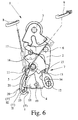
- Fig. 6 shows a comparison with the previously described embodiment slightly modified motor vehicle lock 1, which differs in that the ejector lever 20 provided here next to its normal position I two Ejection positions II, III has.
- the first ejection II is the Ejection lever 20 is decoupled from the operating lever 4.
- the override lever However, 18 is still in the range of movement of the inner actuating chain 5 with the Bowden cable 5 '. This condition is shown in FIG.
- the central locking clutch 13 is so by operating the inside door handle 8 from their functional state CL corresponding position in their the functional state UL corresponding position movable. This function is helpful in a motor vehicle lock 1, wherein the control device 7 For example, when starting the motor vehicle automatically in the functional position CL is moved, but at the same time maintain the child lock becomes. In the case of an accident, it is possible for one child here, another person by pulling on the inside door handle 8 and the associated movement of the Central locking clutch 13 from the functional state CL corresponding Position in the functional state UL corresponding position to allow access. The functional state CS remains unaffected.
- the ejection lever 20 has a second ejection position III, in which the mecanical dysfunction is achieved.
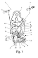
- Fig. 7 shows a comparison with FIG. 1 with respect to the central locking drive 17 modified embodiment.
- the central locking drive 17 has here in addition to the central locking function additionally an opening function on.
- the opening function of the central locking drive 17 is used to the pawl 2 motor from their Einfall ein in their Aushebewolf to relocate.
- the central locking drive 17 is for this purpose as before executed, but still has additional components, by means of which the Opening function is perceptible.
- the control device 7 is as before by means of the central locking drive 17 in a first direction of movement of the functional state CL in the Functional state UL switchable and vice versa in a second direction of movement can be switched from the functional state UL to the functional state CL.
- the opening function of the central locking drive 17 only in the first direction of movement are perceived.
- the range of motion of the central locking drive 17 is not increased for this, but The opening function is part of the already existing movement area of the central locking drive 17 superimposed.
- the control device 7 has the central locking lever 16 as before on, which is motor-driven by means of the central locking drive 17.
- the central locking clutch 13 is provided, which is movable by the central locking lever 16.
- the central locking lever 16 has a control contour 22 for the opening function.
- the control contour 22 is fixed to the central locking lever 16 is located (and lies in Fig. 7 in the drawing plane under the central locking lever 16) and is consequently moved by the movement of the central locking lever 16 moves.
- the control contour 22 is designed as a screw curve, which in the following will be explained in more detail.
- the control device 7 additionally has an opening coupling 23 for the Opening function of the central locking drive 17 on.
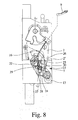
- the opening coupling 23 has an initial position (FIG. 7) and an opening ready position (Figure 8).
- the opening clutch 23 is usually located in its initial position and can only at or after pressing the Door outside handle 9 are moved to its opening ready position.
- the Movement into its opening ready position takes place here and preferably by spring force.
- the opening coupling 23 is in the direction of her Opening ready position biased by a spring 24. In this Position she remains at not actuated door outside handle 9 by a not shown Held element that is operatively connected to the outside door handle 9. However, if the outside door handle 9 is actuated, the spring force effect is released.
- the opening clutch 23 is at least in its opening ready position pivoted. Here and preferably, it is also in its starting position (Fig. 7) pivotally and only to the right in Fig. 7. This is ensures that the movement of the central locking lever 16 at in Starting position located opening clutch 23 is not obstructed.
- the opening ready position is the first of the opening clutch 23 here after completion of the movement of the central locking drive 17 in the second direction of movement ingestible.
- the central locking drive 17 is in the functional state CL.
- the opening clutch 23 has a cam 25 which is in the opening ready position with the pawl 2 can be brought into engagement.
- the actuating arm 2 "of the pawl 2 has a nose 26.
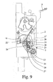
- the control contour 22 in opening ready position located opening coupling 23 with the cam 25 of the opening coupling 23 engaged. If the central locking drive 17 is actuated in this position, d. H. Return of the central locking drive 17 in the functional state UL, so the control contour 22 presses the cam 25 of the opening clutch 23 against the nose 26 of the pawl 2, so that these from their Einfall ein is moved to its Aushebegna (Fig. 9).
- the opening coupling 23 is pivotally mounted on a coupling carrier 27.
- the coupling carrier 27 has a slot 28 in which the Opening coupling 23 is mounted.
- the opening clutch 23 is in the Slot 28 of the coupling carrier 27 by the spring 24 from its initial position displaceable in the opening ready position.
- the coupling carrier 27 has a stop 29 against which the opening coupling 23 in the opening ready position is biased by a spring 30.
- the bias against the stop 29 and the design of the control contour 22 as a screw curve serve that the pawl 2 only by the movement of the central locking drive 17 in the first direction of movement can be lifted, but not by the movement of the central locking drive 17 in the second direction of movement. This ensures that that the opening function of the central locking drive 17 only executed if this is really desired, d. H. if the system is in itself is still in the functional state CL, but the outside door handle 9 already - too fast for the system - has been pressed.
- the central locking drive 17 is designed here so that he can be operated in block mode. That is, preferably both Movement directions of the central locking drive 17 by a stop (not shown) are limited.
- the central locking function of the central locking drive 17 is here as in the embodiments described with reference to FIGS. 1 to 6.
- the first direction of movement of the central locking drive 17th here is additionally superimposed the opening function, by the interaction the control contour 22, the opening clutch 23 and the nose 26 of the Pawl 2 is executed.
- the opening function takes place here and preferably only then motor, if the operation of the outside door handle 9 so quickly done that the controller 7 from its functional state CL or DL can not be switched into their functional state UL fast enough could.
- the central locking lever 16 is in this case at Operation of the outside door handle 9 still in its functional state CL or DL corresponding position of the control device 7.
- the actuation of the Outside door handle 9 allows the displacement of the opening clutch 23 from their initial position in their opening ready position, so that the subsequent Movement of the central locking drive 17 in the first direction of movement for lifting the pawl 2 leads. Another one Actuation of the outside door handle 9 is thus not required, since the opening in this case is done by motor.
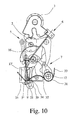
- Fig. 10 shows a further embodiment, which is in operation does not differ significantly from the previously described embodiments.
- the pawl 2 in turn has the Einfall ein on, in which it holds the latch 3 in the closed position and the Pick-up position in which the latch 3 is released.
- the pawl 2 is by means of the actuating chains 4, 5 from the incidence position to the release position as a function of the functional state of the control device 7 displaced.
- the motor vehicle lock 1 shown here (FIG. 10) is located in FIG Functional status UL.
- the control device 7 in turn has various means for modification of the functional state.
- the ejection lever 20 exemplifies a means for Change of the functional state described.
- the ejection lever 20 is pivotally mounted and has the slot 21, in which the pin 5 'of a Bowden cable 5 "of the inner actuating chain 5 runs.
- the ejection lever 20 is in the functional states UL (FIG. 10). and CL of the control device 7 in its normal position.
- UL FIG. 10
- CL the functional states
- CS Fig. 11
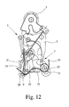
- DL Fig. 12
- the ejection lever 20 manually and / or motor by the drive 17 'are moved back and forth between its functional positions.
- the motor vehicle lock 1 described here has a spring 31 on, which is designed here as a leg spring with the legs 32 and 33.
- the spring 31 is mounted here fixed on the pivot axis 12.
- the Bowden cable 5 "of the inner actuating chain 5 is by the spring 31 in the direction of his Starting position spring loaded.
- starting position of the Bowden cable 5 " is Here denotes the position in which the Bowden cable 5 "is located when the Door inner handle 8 is not actuated and the control device 7 in the functional state UL is located ( Figure 10).
- the spring 31 has a second function. In this second function poses the spring 31 is a limit switch for the eject lever 20 of the controller 7 ready.
- the term “Endlagenentechnisch” means here that the Eject lever 20 is held by the spring 31 in a desired position. This can be done by being active by the spring 31 by means of spring force in this position is pressed. Alternatively, the spring 31 in this Position of the ejection lever 20 but also rest relaxed, wherein moving the eject lever 20 from this position out only against Spring force is possible.
- the ejection lever 20 is located in the second function essentially only on the spring 31. This does not exclude, however, that the spring 31 when the eject lever 20 is already curious to a small extent.
- the spring 31 has here and preferably for each Their functions have their own contour 34, 35. Both contours 34, 35 are here and preferably arranged on the same leg 32 of the spring 31, so that the components affected by the two functions of the spring 31, namely the Bowden cable 5 "and the ejection slide 20, with the same Leg 32 of the spring 31 cooperate.
- the ejection lever 20 itself acts only insofar with the leg 32 of the spring 31 together, as that he by the storage of the Bowden cable 5 "in the slot 21 of the eject lever 20 with respect to the second function of the spring 31 with spring loaded is.
- the other leg 33 of the spring 31, however, is located on a fixed stop (not shown) of the motor vehicle lock 1 on.
- the contour 34 for the first function of the spring 31 is formed by that the leg 32 of the spring 31 here and preferably opposite to the direction the bend of the actual spring winding of the spring 31 is bent. These Bending and possibly this subsequent or arranged in the bend straight portions of the leg 32 of the spring 31 form the contour 34th for the first function.
- the pin 5 'of the Bowden cable 5 "so that the Bowden cable 5" in the direction of its initial position is spring loaded.
- the contour 34 acts insofar as an investment for the Bowden cable 5 ". This means that the pin 5 'of the Bowden cable 5" in Normal position on the contour 34 of the spring 31 is applied, the spring 31 substantially but not tense.
- the second Bending of the leg 32 is preferably carried out by about 90 °. It is, however also considerably larger and smaller bending angles possible.
- the bending radius is here and preferably so small that the leg 32 of the spring 31 substantially is bent.
- the area behind the second bend of the leg 32 of the spring 31 forms the second contour 35 for the second function of the spring 31.
- the spring 31 is used in its second function as a facility for the ejection lever 20 when the Control device 7 is located in the functional states DL or CS. Only in These functional states is the eject lever 20 from its normal position moved out.
- the pin 5 'of the Bowden cable 5 "in the slot 21 of the Eject lever 20 is guided, then lies on the second contour 35 of the spring 31 on.
- the second contour 35 forms the attachment for the second function the spring 31.
- the ejection lever 20 is thus through the interaction with the Bowden cable 5 "in the functional states DL and CS of the control device 7 corresponding Position spring loaded.
- the spring 31 acts so with the Bowden cable of the Bowden cable 5 "together that the eject lever 20 in this position by a spring action of the Bowden cable soul in the transverse direction is biased against the serving as a plant contour 35 of the spring 31.
- the Spring effect of the Bowden cable in the transverse direction is the result of inherent elasticity the bowden cable soul. Under the transverse direction is a direction in understood transversely to the longitudinal extent of the Bowden cable 5 ".
- the spring action of the Bowden cable of the Bowden cable 5 " is the Position of the eject lever 20 precisely defined.
- the eject lever 20 instead of the spring effect of the Bowden cable of the Bowden cable 5 "or in addition To this, the eject lever 20 also by an additional spring (not shown) to be biased against the system.
- the contour 35 is designed here so long that upon actuation of the inside door handle 8 in the functional position CS (FIG. 11) or DL (FIG. 12) Control device 7 of the pin 5 'of the Bowden cable 5 "the spring 31 not to Press side and can slip past this. Instead, the spring 31 on actuation of the door inner handle 8 so tense that the pin 5 'of the Bowden cable 5 "after releasing the inside door handle 8 in its original Position returns.
- the leg 32 may be bent at its end a third time. This also makes it possible to prevent the pin 5 'from slipping on the spring 31 to prevent.
- the spring 31 on the one hand simple return spring for the Bowden cable is on the other hand by the contours 34, 35 and the function a tilting spring in the sense of just a limit of Bowdenzugseele and eject lever 20 has.
Landscapes
- Health & Medical Sciences (AREA)
- Child & Adolescent Psychology (AREA)
- Lock And Its Accessories (AREA)
Abstract
Description
- Fig. 1
- eine schematische Darstellung eines Kraftfahrzeugschlosses im Funktionszustand UL,
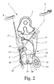
- Fig. 2
- das Kraftfahrzeugschloß aus Fig. 1 im Funktionszustand CL,
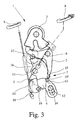
- Fig. 3
- das Kraftfahrzeugschloß aus Fig. 2 mit gezogenem Türaußengriff,
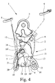
- Fig. 4
- das Kraftfahrzeugschloß aus Fig. 1 im Funktionszustand DL,
- Fig. 5
- das Kraftfahrzeugschloß aus Fig. 1 im Funktionszustand CS,
- Fig. 6
- ein weiteres Kraftfahrzeugschloß im Funktionszustand CS,
- Fig. 7
- ein weiteres Kraftfahrzeugschloß im Funktionszustand UL mit der Öffnungskupplung in Ausgangsstellung,
- Fig. 8
- das Kraftfahrzeugschloß aus Fig. 7 im Funktionszustand CL und mit der Öffnungskupplung in Öffnungsbereitschaftsstellung,
- Fig. 9
- das Kraftfahrzeugschloß aus Fig. 8 mit ausgeführter Öffnungsfunktion des Zentralverriegelungsantriebs,
- Fig. 10
- ein weiteres Kraftfahrzeugschloß, erneut im Funktionszustand UL,
- Fig. 11
- das Kraftfahrzeugschloß aus Fig. 10 im Funktionszustand CS,
- Fig. 12
- das Kraftfahrzeugschloß aus Fig. 10 im Funktionszustand DL.
Claims (22)
- Kraftfahrzeugschloß (1) mit einer Sperrklinke (2), einer Schloßfalle (3), einem Betätigungshebel (4), einer Innenbetätigungskette (5), einer Außenbetätigungskette (6) und einer Steuereinrichtung (7),
wobei die Sperrklinke (2) eine Einfallstellung, in der sie die Schloßfalle (3) in einer Schließstellung hält, und eine Aushebestellung, in der die Schloßfalle (3) freigegeben ist, aufweist,
wobei die Sperrklinke (2) mittels des Betätigungshebels (4) von der Einfallstellung in die Aushebestellung verlagerbar ist,
wobei die Steuereinrichtung (7) verschiedene Funktionszustände aufweist und
wobei je nach Funktionszustand der Steuereinrichtung (7) die Sperrklinke (2) über den Betätigungshebel (4) mittels der Innenbetätigungskette (5) von einem Türinnengriff (8) und/oder mittels der Außenbetätigungskette (6) von einem Türaußengriff (9) oder gar nicht betätigbar ist,
dadurch gekennzeichnet, daß die Steuereinrichtung (7) einen Grundzustand hat, in dem die Innenbetätigungskette (5) und die Außenbetätigungskette (6) mit dem Betätigungshebel (4) gekoppelt sind und
daß die Innenbetätigungskette (5) und/oder die Außenbetätigungskette (6) mittels der Steuereinrichtung (7) von dem Betätigungshebel (4) je nach Funktionszustand entkoppelbar ist. - Kraftfahrzeugschloß nach Anspruch 1, dadurch gekennzeichnet, daß die Innenbetätigungskette (5) und/oder die Außenbetätigungskette (6) bzgl. des Betätigungshebels (4) so gelagert ist, daß die eine Kette (5; 6) bei Betätigung des Betätigungshebels (4) mittels der anderen Kette (6; 5) nicht mitbewegt wird.
- Kraftfahrzeugschloß nach Anspruch 1 oder 2, dadurch gekennzeichnet, daß die Innenbetätigungskette (5) und/oder die Außenbetätigungskette (6) am Betätigungshebel (4) nur einseitig anschlagend oder in einem Langloch geführt ist.
- Kraftfahrzeugschloß nach einem der vorhergehenden Ansprüche, dadurch gekennzeichnet, daß die Innenbetätigungskette (5) und/oder die Außenbetätigungskette (6) als Bowdenzug ausgeführt ist.
- Kraftfahrzeugschloß nach einem der vorhergehenden Ansprüche, dadurch gekennzeichnet, daß die Betätigung seitens der Innenbetätigungskette (5) und die Betätigung seitens der Außenbetätigungskette (6) eine Bewegung des Betätigungshebels (4) in der selben Bewegungsrichtung bewirkt.
- Kraftfahrzeugschloß nach einem der vorhergehenden Ansprüche, dadurch gekennzeichnet, daß die Steuereinrichtung (7) eine Zentralverriegelungskupplung (13) aufweist, durch die jedenfalls die Funktionszustände "UL" und "CL" einschaltbar sind,
wobei, vorzugsweise, die Sperrklinke (2) und der Betätigungshebel (4) im Funktionszustand (CL) wirkungsmäßig entkoppelt sind, und/oder
wobei, vorzugsweise, die Zentralverriegelungskupplung (13) einen Nocken (15) aufweist, mit dem die Sperrklinke (2) und der Betätigungshebel (4) im Funktionszustand "UL" der Steuereinrichtung (7) wirkungsmäßig gekoppelt sind und jedenfalls im Funktionszustand "CL" wirkungsmäßig entkoppelt sind, und/oder
wobei, vorzugsweise, die Steuereinrichtung (7) einen Zentralverriegelungshebel (16) aufweist, mit dem die Zentralverriegelungskupplung (13) von ihrer jedenfalls dem Funktionszustand "UL" der Steuereinrichtung (7) entsprechenden Stellung in ihre jedenfalls dem Funktionszustand "CL" entsprechende Stellung bewegbar ist. - Kraftfahrzeugschloß nach Anspruch 6, dadurch gekennzeichnet, daß die Steuereinrichtung (7) einen Zentralverriegelungsantrieb (17) zum motorischen Antreiben des Zentralverriegelungshebels (16) aufweist, und/oder
daß der Zentralverriegelungshebel (16) jedenfalls im Funktionszustand "CL" der Steuereinrichtung (7) formschlüssig mit der Zentralverriegelungskupplung (13) in Eingriff steht. - Kraftfahrzeugschloß nach Anspruch 6 oder 7, dadurch gekennzeichnet, daß die Steuereinrichtung (7) einen Überholhebel (18) aufweist, der so mittels der Innenbetätigungskette (5) durch Betätigung des Türinnengriffs (8) bewegbar ist, daß die Zentralverriegelungskupplung (13) von ihrer jedenfalls dem Funktionszustand "CL" entsprechenden Stellung in ihre jedenfalls dem Funktionszustand "UL" entsprechende Stellung bewegbar ist,
wobei, vorzugsweise, ein einziger Hub des Türinnengriffs (8) nacheinander die Steuereinrichtung (7) in den Funktionszustand "UL" bewegt und die Sperrklinke (2) in ihre Aushebestellung verlagert, oder
ein erster Hub des Türinnengriffs (8) die Steuereinrichtung (7) in den Funktionszustand "UL" bewegt und daß ein zweiter Hub des Türinnengriffs (8) die Sperrklinke (2) in ihre Aushebestellung verlagert. - Kraftfahrzeugschloß nach einem der Ansprüche 6 bis 8, dadurch gekennzeichnet, daß die Steuereinrichtung (7) einen Funktionszustand "DL" aufweist, in dem die Sperrklinke (2) weder durch die Innenbetätigungskette (5) noch durch die Außenbetätigungskette (6) betätigbar ist,
wobei, vorzugsweise, die Zentralverriegelungskupplung (13) sich im Funktionszustand "DL" in ihrer dem Funktionszustand "CL" entsprechenden Stellung befindet und die Innenbetätigungskette (5) von dem Betätigungshebel (4) entkoppelt ist und/oder
wobei, vorzugsweise, die Innenbetätigungskette (5) im Funktionszustand "DL" aus dem Wirkungsbereich des Betätigungshebels (4) und, sofern dieser vorhanden ist, des Überholhebels (18) herausgeschwenkt ist. - Kraftfahrzeugschloß nach Anspruch 9, dadurch gekennzeichnet, daß die Innenbetätigungskette (5) einen Auswurfhebel (20) zum Entkoppeln der Innenbetätigungskette (5) von dem Betätigungshebel (4) aufweist,
wobei, vorzugsweise, der Auswurfhebel (20) ein Langloch (21) aufweist, in dem ein Zapfen (5') der Innenbetätigungskette (5), insbesondere eine Betätigungstonne (5') eines Bowdenzugs, läuft. - Kraftfahrzeugschloß nach einem der vorhergehenden Ansprüche, dadurch gekennzeichnet, daß die Steuereinrichtung (7) einen Antrieb (17') zur Realisierung des Funktionszustandes DL bzw. CS aufweist und daß die Innenbetätigungskette (5) von dem Betätigungshebel (4) motorisch entkoppelbar ist.
- Kraftfahrzeugschloß mit einer Sperrklinke (2), einer Schloßfalle (3) und einer Steuereinrichtung (7),
wobei die Sperrklinke (2) eine Einfallstellung, in der sie die Schloßfalle (3) in einer Schließstellung hält, und eine Aushebestellung, in der die Schloßfalle (3) freigegeben ist, aufweist,
wobei die Steuereinrichtung (7) einen Zentralverriegelungsantrieb (17) aufweist,
wobei die Steuereinrichtung (7) mittels des Zentralverriegelungsantriebs (17) in einer ersten Bewegungsrichtung jedenfalls von einem Funktionszustand CL in einen Funktionszustand UL und in einer zweiten Bewegungsrichtung jedenfalls von dem Funktionszustand UL in den Funktionszustand CL schaltbar ist,
wobei der Zentralverriegelungsantrieb (17) zusätzlich als Öffnungsantrieb eingerichtet ist und die Sperrklinke (2) mittels des Zentralverriegelungsantriebs (17) in der Öffnungsfunktion von der Einfallstellung in die Aushebestellung verlagerbar ist,
insbesondere nach einem der Ansprüche 1 bis 11,
dadurch gekennzeichnet, daß die Öffnungsfunktion in der ersten Bewegungsrichtung des Zentralverriegelungsantriebs (17) erfolgt und
daß der Bewegungsbereich des Zentralverriegelungsantriebs (17) in der Zentralverriegelungsfunktion wenigstens teilweise mit dem Bewegungsbereich des Zentralverriegelungsantriebs (17) in der Öffnungsfunktion zusammenfällt. - Kraftfahrzugschloß nach Anspruch 12, dadurch gekennzeichnet, daß die Steuereinrichtung (7) einen Zentralverriegelungshebel (16) aufweist, der mittels des Zentralverriegelungsantriebs (17) motorisch antreibbar ist,
wobei, vorzugsweise, der Zentralverriegelungshebel (16) eine Steuerkontur (22) für die Öffnungsfunktion aufweist, die vorzugsweise als Schneckenkurve ausgeführt ist. - Kraftfahrzeugschloß nach Anspruch 12 oder 13, dadurch gekennzeichnet, daß die Steuereinrichtung (7) eine Öffnungskupplung (23) mit einer Öffnungsbereitschaftsstellung und einer Ausgangsstellung aufweist und daß die Öffhungsbereitschaftsstellung von der Öffnungskupplung (23) jedenfalls nach Beendigung der Bewegung des Zentralverriegelungsantriebs (17) in der zweiten Bewegungsrichtung einnehmbar ist,
wobei, vorzugsweise, die Öffnungskupplung (23) einen Nocken (25) aufweist, der in der Öffnungsbereitschaftsstellung mit der Sperrklinke (2) in Eingriff bringbar ist und daß die Steuerkontur (22) bei in Öffnungsbereitschaftsstellung befindlicher Öffnungskupplung (23) mit dem Nocken (25) der Öffnungskupplung (23) in Eingriff bringbar ist. - Kraftfahrzeugschloß nach Anspruch 14 mit einem Türaußengriff (9), dadurch gekennzeichnet, daß die Öffnungskupplung (23) in Richtung ihrer Öffnungsbereitschaftsstellung vorgespannt ist, daß die Öffnungskupplung (23) in ihrer Ausgangsstellung durch den nicht betätigten Türaußengriff (9) gehalten ist und aus ihrer Ausgangsstellung durch Betätigung des Türaußengriffs (9) freigebbar und erst dann in ihre Öffnungsbereitschaftsstellung bewegbar ist.
- Kraftfahrzeugschloß nach Anspruch 14 oder 15, dadurch gekennzeichnet, daß ein Kupplungsträger (27) für die Öffnungskupplung (23) vorgesehen ist, daß der Kupplungsträger (27) ein Langloch (28) aufweist und daß die Öffnungskupplung (23) in dem Langloch (28) gelagert ist und/oder
daß der Kupplungsträger (27) einen Anschlag (29) für die Öffnungskupplung (23) aufweist und daß die Öffnungskupplung (23) in Richtung des Anschlags (29) vorgespannt ist. - Kraftfahrzeugschloß nach einem der Ansprüche 14 bis 16, dadurch gekennzeichnet, daß die Sperrklinke (2) bei in Öffnungsbereitschaftsstellung stehender Öffnungskupplung (23) durch die Bewegung des Zentralverriegelungsantriebs (17) in der ersten Bewegungsrichtung aushebbar ist, jedoch durch die Bewegung des Zentralverriegelungsantriebs (17) in der zweiten Bewegungsrichtung generell nicht aushebbar ist.
- Kraftfahrzeugschloß nach einem der vorhergehenden Ansprüche, dadurch gekennzeichnet, daß eine Feder (31) vorgesehen ist, die in einer ersten Funktion ein Element (5") einer Betätigungskette (5) oder ein sonstiges Mittel zur Änderung des Funktionszustandes (20) in eine Richtung federbeaufschlagt,
daß die Feder (31) eine zweite Funktion aufweist und daß die zweite Funktion eine Endlagensicherung für das Element (5") der Betätigungskette (5) und/oder das Mittel zur Änderung des Funktionszustandes (20) ist. - Kraftfahrzeugschloß nach Anspruch 18, dadurch gekennzeichnet, daß die Feder (31) für jede ihrer Funktionen eine eigene Kontur (34, 35) aufweist und/oder
daß die Feder (31) als Schenkelfeder ausgeführt ist, wobei, vorzugsweise, die Feder (31) so ausgeführt ist, daß die von den beiden Funktionen der Feder (31) betroffenen Bauteile (5", 20) mit dem gleichen Schenkel (32) der Feder (31) zusammenwirken. - Kraftfahrzeugschloß nach Anspruch 18 oder 19, dadurch gekennzeichnet, daß ein Schenkel (32) der Feder (31) in seinem Verlauf abgebogen ist und durch die Biegung der Feder (31) eine Kontur (34) für die erste Funktion sowie eine Kontur (3 5) für die zweite Funktion der Feder (31) gebildet ist.
- Kraftfahrzeugschloß nach Anspruch 18 oder 19, dadurch gekennzeichnet, daß die Feder (31) so mit dem Element (5") zusammenwirkt, daß die Feder (31) bei nicht betätigtem Türinnengriff (8) im wesentlichen eine Anlage für das Element (5") bildet und das Element (5") durch die Feder (31) in Richtung seiner Ausgangslage federbeaufschlagt ist,
wobei, vorzugsweise, die Betätigungskette (5) als Bowdenzug ausgeführt ist und daß die Feder (31) so mit der Seele des Bowdenzugs zusammenwirkt, daß das Element (5") oder das Mittel zur Änderung des Funktionszustandes in der Funktionsstellung, in der die Feder (31) als Anlage dient, durch eine Federwirkung der Bowdenzugseele in Querrichtung gegen die Anlage vorgespannt ist. - Kraftfahrzeugschloß nach einem der Ansprüche 18 bis 21, dadurch gekennzeichnet, daß das Mittel zur Änderung des Funktionszustandes ein Auswurfhebel (20) ist, mit dem die Innenbetätigungskette (5) vom Betätigungshebel (4) entkoppelbar ist.
Applications Claiming Priority (6)
| Application Number | Priority Date | Filing Date | Title |
|---|---|---|---|
| DE200410014551 DE102004014551A1 (de) | 2004-03-23 | 2004-03-23 | Kraftfahrzeugschloß |
| DE102004014550 | 2004-03-23 | ||
| DE200410014550 DE102004014550A1 (de) | 2004-03-23 | 2004-03-23 | Kraftfahrzeugschloß |
| DE102004014551 | 2004-03-23 | ||
| DE102004017014A DE102004017014A1 (de) | 2004-04-02 | 2004-04-02 | Kraftfahrzeugschloss |
| DE102004017014 | 2004-04-02 |
Publications (2)
| Publication Number | Publication Date |
|---|---|
| EP1580366A2 true EP1580366A2 (de) | 2005-09-28 |
| EP1580366A3 EP1580366A3 (de) | 2009-10-28 |
Family
ID=34864749
Family Applications (1)
| Application Number | Title | Priority Date | Filing Date |
|---|---|---|---|
| EP20050004873 Withdrawn EP1580366A3 (de) | 2004-03-23 | 2005-03-05 | Kraftfahrzeugschloss |
Country Status (2)
| Country | Link |
|---|---|
| US (1) | US7568740B2 (de) |
| EP (1) | EP1580366A3 (de) |
Cited By (5)
| Publication number | Priority date | Publication date | Assignee | Title |
|---|---|---|---|---|
| DE202007013330U1 (de) * | 2007-09-21 | 2009-02-12 | BROSE SCHLIEßSYSTEME GMBH & CO. KG | Kraftfahrzeugschloß |
| DE202009007355U1 (de) | 2009-05-22 | 2010-10-21 | BROSE SCHLIEßSYSTEME GMBH & CO. KG | Kraftfahrzeugschloss |
| EP2199502A3 (de) * | 2008-12-18 | 2014-02-26 | Brose Schliesssysteme GmbH & Co. KG | Kraftfahrzeugschloss |
| EP2228508A4 (de) * | 2008-01-10 | 2014-10-29 | Aisin Seiki | Türverriegelungsvorrichtung für fahrzeuge |
| US20260062965A1 (en) * | 2022-09-06 | 2026-03-05 | Kiekert Aktiengesellschaft | Motor vehicle lock |
Families Citing this family (32)
| Publication number | Priority date | Publication date | Assignee | Title |
|---|---|---|---|---|
| DE202005015687U1 (de) * | 2005-10-05 | 2007-02-15 | BROSE SCHLIEßSYSTEME GMBH & CO. KG | Kraftfahrzeugschloß |
| CN101657590B (zh) * | 2007-03-01 | 2012-08-22 | 马格纳·克劳祖雷斯有限公司 | 用于车辆被动进入门锁的双锁超控机构 |
| DE102008018500A1 (de) | 2007-09-21 | 2009-04-02 | BROSE SCHLIEßSYSTEME GMBH & CO. KG | Kraftfahrzeugschloß |
| EP2050903B1 (de) * | 2007-10-17 | 2012-06-27 | Huf Hülsbeck & Fürst GmbH & Co. KG | Verschluss für Fahrzeuge |
| DE102008011545A1 (de) * | 2008-02-28 | 2009-09-03 | Kiekert Ag | Kraftfahrzeugtürverschluss |
| GB2458574B (en) * | 2008-03-26 | 2011-06-08 | Mitsui Mining & Smelting Co | Door lock apparatus |
| JP4473919B2 (ja) * | 2008-03-31 | 2010-06-02 | 三井金属鉱業株式会社 | 自動車用ドアラッチ装置 |
| DE102008028256A1 (de) * | 2008-06-13 | 2009-12-24 | Kiekert Ag | Schließvorrichtung mit zwei Sperrklinken und motorisch angetriebenen Stellantrieb |
| DE202008012484U1 (de) | 2008-09-21 | 2010-02-18 | BROSE SCHLIEßSYSTEME GMBH & CO. KG | Kraftfahrzeugschloß |
| JP5003843B2 (ja) * | 2009-03-27 | 2012-08-15 | アイシン精機株式会社 | 車両用ドアロック装置 |
| DE102010003483B4 (de) * | 2009-06-12 | 2019-08-01 | Kiekert Ag | Schloss mit Zwangsführung für Sperrklinke |
| US9194163B2 (en) * | 2011-01-14 | 2015-11-24 | Magna Closures S.P.A. | Door latch with opening memory feature |
| US8701817B2 (en) * | 2011-12-12 | 2014-04-22 | Chrysler Group Llc | Impact sensitive latch actuation link for vehicle door |
| DE102012020424A1 (de) * | 2012-10-18 | 2014-02-20 | Kiekert Aktiengesellschaft | Kraftfahrzeugtürschloss |
| DE102012023236A1 (de) * | 2012-11-28 | 2014-05-28 | Kiekert Aktiengesellschaft | Kraftfahrzeugtürschloss |
| US9920555B2 (en) * | 2013-01-18 | 2018-03-20 | Kiekert Ag | Lock for a motor vehicle |
| GB201408075D0 (en) * | 2014-05-07 | 2014-06-18 | Chevalier John P | Closure and latching mechanisms |
| KR101560979B1 (ko) * | 2014-05-30 | 2015-10-15 | 평화정공 주식회사 | 2단 해제용 후드래치 |
| US20160168883A1 (en) * | 2014-12-15 | 2016-06-16 | GM Global Technology Operations LLC | Double pull action vehicle hood latch |
| FR3038643A1 (de) * | 2015-07-06 | 2017-01-13 | Inteva Products Llc | |
| CN107620529B (zh) | 2016-07-15 | 2020-12-15 | 株式会社安成 | 车辆用门锁装置 |
| CN107642287B (zh) | 2016-07-20 | 2020-08-28 | 株式会社安成 | 车辆用门锁装置 |
| JP6627672B2 (ja) | 2016-07-20 | 2020-01-08 | 株式会社アンセイ | 車両用ドアロック装置 |
| JP6703271B2 (ja) * | 2016-09-21 | 2020-06-03 | 株式会社アンセイ | 車両用ドアロック装置 |
| JP6627729B2 (ja) | 2016-11-25 | 2020-01-08 | 株式会社アンセイ | 車両用ドアロック装置 |
| JP6707062B2 (ja) * | 2017-07-20 | 2020-06-10 | 三井金属アクト株式会社 | 自動車用ドアラッチ装置 |
| US10808437B2 (en) * | 2017-07-21 | 2020-10-20 | Kiekert Ag | Motor vehicle door latch with primary and secondary pawl |
| JP6627920B2 (ja) | 2018-06-26 | 2020-01-08 | 株式会社アンセイ | 車両用ドアロック装置 |
| DE102020110454A1 (de) * | 2020-04-16 | 2021-10-21 | Kiekert Aktiengesellschaft | Kraftfahrzeug-Schloss, insbesondere Kraftfahrzeug-Türschloss |
| US12331572B2 (en) | 2022-05-03 | 2025-06-17 | Arctic Cat Inc. | Dual-action door handle |
| JP7827980B2 (ja) | 2022-06-06 | 2026-03-11 | 株式会社アンセイ | 車両用開閉体のロック装置 |
| US12258794B2 (en) * | 2022-07-13 | 2025-03-25 | Kiekert Ag | Motor vehicle latch, in particular a motor vehicle door latch |
Family Cites Families (28)
| Publication number | Priority date | Publication date | Assignee | Title |
|---|---|---|---|---|
| IT1131405B (it) * | 1979-03-24 | 1986-06-25 | Kiekert Soehne Arn | Dispositivo di chiusura a comando centralizzato per porte di veicoli a motore |
| US5474339A (en) * | 1993-10-15 | 1995-12-12 | Kelsey-Hayes Company | Door latch with double locking antitheft feature |
| IT1268616B1 (it) | 1994-10-04 | 1997-03-06 | Roltra Morse Spa | Serratura ad azionamento elettrico per una portiera di un autoveicolo. |
| US5921595A (en) | 1995-05-24 | 1999-07-13 | Kiekert Ag | Motor-vehicle door latch with single-handle inside actuation |
| DE19631869A1 (de) | 1996-08-07 | 1998-02-12 | Bosch Gmbh Robert | Kraftfahrzeug-Türschloß oder dergleichen |
| DE19635414C2 (de) * | 1996-08-31 | 2001-07-12 | Mannesmann Vdo Ag | Schloß, insbesondere für Fahrzeugtüren oder dergleichen |
| DE19702420C5 (de) * | 1997-01-24 | 2009-12-31 | Audi Ag | Steuervorrichtung für einen Verschluß, insbesondere von Kraftfahrzeugtüren |
| FR2766861B1 (fr) * | 1997-07-31 | 1999-09-03 | Valeo Systemes De Fermetures | Serrure de porte de vehicule automobile a condamnation electrique |
| DE29804649U1 (de) * | 1998-03-14 | 1998-05-14 | Schloß- und Metallwarenfabrik Böddecker & Co. GmbH & Co. KG, 42327 Wuppertal | Motorhaubenverschluß für ein Kraftfahrzeug |
| US6067826A (en) * | 1998-06-11 | 2000-05-30 | Stoneridge, Inc. | Door lock actuator |
| DE19841670C2 (de) * | 1998-09-11 | 2001-01-11 | Mannesmann Vdo Ag | Schließeinrichtung |
| GB2342383B (en) * | 1998-10-06 | 2002-07-17 | Meritor Light Vehicle Sys Ltd | Door latch |
| FR2785638B1 (fr) | 1998-11-09 | 2000-12-29 | Valeo Securite Habitacle | Serrure de porte a condamnation/decondamnation electrique exterieure et/ou interieur pour vehicule automobile |
| DE19853056A1 (de) * | 1998-11-17 | 2000-05-18 | Delphi Automotive Systems Gmbh | Riegelbetätigungsvorrichtung |
| FR2786522B1 (fr) * | 1998-11-26 | 2001-06-08 | Valeo Securite Habitacle | Serrure pour portiere de vehicule automobile |
| DE19913590C2 (de) * | 1999-03-24 | 2003-11-06 | Kiekert Ag | Zentralverriegelungsanlage für ein Kraftfahrzeug |
| JP3301738B2 (ja) * | 1999-04-21 | 2002-07-15 | 三井金属鉱業株式会社 | ダブルアクション機構付車両ドアラッチ装置 |
| GB2358430B (en) * | 1999-04-21 | 2002-02-20 | Mitsui Mining & Smelting Co | Vehicle door latch device with double action mechanism |
| DE19948315B4 (de) | 1999-10-07 | 2005-06-09 | Brose Schließsysteme GmbH & Co.KG | Kraftfahrzeug-Türschloß |
| DE19955882C2 (de) | 1999-11-20 | 2003-10-23 | Kiekert Ag | Kraftfahrzeugtürverschluss |
| DE10038151C2 (de) | 2000-08-04 | 2003-03-20 | Kiekert Ag | Kraftfahrzeugtürverschluss |
| DE50111505D1 (de) | 2000-09-07 | 2007-01-04 | Brose Schliesssysteme Gmbh | Kraftfahrzeug-türschloss mit kombiniertem zentralverriegelungs- und öffnungsantrieb |
| FR2816073B1 (fr) * | 2000-10-26 | 2003-09-12 | Peugeot Citroen Automobiles Sa | Dispositif de commande d'un ou de plusieurs mecanismes, notamment d'ouvrant de vehicule automobile |
| DE10131412B4 (de) | 2000-11-17 | 2008-08-28 | Brose Fahrzeugteile Gmbh & Co. Kommanditgesellschaft, Coburg | Kraftfahrzeugtür |
| DE10131965B4 (de) * | 2000-12-07 | 2009-01-22 | Witte-Strattec Llc, Troy | Schloss mit von einer Sperrklinke in einer Geschlossenstellung gehaltenen Falle |
| DE10239698A1 (de) | 2002-08-29 | 2004-03-11 | Witte-Velbert Gmbh & Co. Kg | Verschluss, insbesondere für Kraftfahrzeugtüren |
| DE20216847U1 (de) * | 2002-10-30 | 2004-03-04 | Brose Fahrzeugteile Gmbh & Co. Kg, Coburg | Funktionssteuerung für ein Schließsystem einer Kraftfahrzeugtür |
| DE10258646B3 (de) * | 2002-12-13 | 2004-05-19 | Brose Schließsysteme GmbH & Co.KG | Kraftfahrzeug-Türschloß |
-
2005
- 2005-03-05 EP EP20050004873 patent/EP1580366A3/de not_active Withdrawn
- 2005-03-23 US US11/086,681 patent/US7568740B2/en not_active Expired - Fee Related
Cited By (6)
| Publication number | Priority date | Publication date | Assignee | Title |
|---|---|---|---|---|
| DE202007013330U1 (de) * | 2007-09-21 | 2009-02-12 | BROSE SCHLIEßSYSTEME GMBH & CO. KG | Kraftfahrzeugschloß |
| EP2228508A4 (de) * | 2008-01-10 | 2014-10-29 | Aisin Seiki | Türverriegelungsvorrichtung für fahrzeuge |
| EP2199502A3 (de) * | 2008-12-18 | 2014-02-26 | Brose Schliesssysteme GmbH & Co. KG | Kraftfahrzeugschloss |
| DE202009007355U1 (de) | 2009-05-22 | 2010-10-21 | BROSE SCHLIEßSYSTEME GMBH & CO. KG | Kraftfahrzeugschloss |
| EP2253786A2 (de) | 2009-05-22 | 2010-11-24 | Brose Schliesssysteme GmbH & Co. KG | Kraftfahrzeugschloss |
| US20260062965A1 (en) * | 2022-09-06 | 2026-03-05 | Kiekert Aktiengesellschaft | Motor vehicle lock |
Also Published As
| Publication number | Publication date |
|---|---|
| US20050218661A1 (en) | 2005-10-06 |
| EP1580366A3 (de) | 2009-10-28 |
| US7568740B2 (en) | 2009-08-04 |
Similar Documents
| Publication | Publication Date | Title |
|---|---|---|
| EP1580366A2 (de) | Kraftfahrzeugschloss | |
| EP2342405B1 (de) | Kraftfahrzeugschloss | |
| DE19841309C2 (de) | Schloß für Klappen, Türen oder dgl. von Fahrzeugen, insbesondere Handschuhfach-Schloß | |
| DE102008018500A1 (de) | Kraftfahrzeugschloß | |
| EP2420642B1 (de) | Kraftfahrzeugschloss | |
| EP2291571A1 (de) | Schliessvorrichtung mit sperrklinkenfeder | |
| EP1457625A2 (de) | Kraftfahrzeugschloss mit elektrischem Öffnungsantrieb | |
| DE102004014550A1 (de) | Kraftfahrzeugschloß | |
| WO2007121724A2 (de) | Kraftfahrzeugtürverschluss | |
| EP1143093B1 (de) | Kraftfahrzeug-Türschloss mit elastisch auslenkbarem Kupplungselement | |
| EP2133497B1 (de) | Kraftfahrzeugtürschloß | |
| EP1637675B1 (de) | Drehfallen-Verriegelung für Türen von Fahrzeugen des öffentlichen Personenverkehrs, insbesondere von Schienenfahrzeugen | |
| WO2019063755A1 (de) | Kraftfahrzeugschloss | |
| DE19805388B4 (de) | Türschloß mit einer Öffnungshilfe | |
| DE10042191A1 (de) | Kraftfahrzeug-Türschloß mit gesteuertem Stellelement | |
| DE10319743B4 (de) | Kraftfahrzeugschloß mit elektrischem Öffnungsantrieb | |
| DE202007013330U1 (de) | Kraftfahrzeugschloß | |
| DE102018125137A1 (de) | Elektromotorische Kraftfahrzeug-Antriebseinheit | |
| EP4499959A1 (de) | Kraftfahrzeug-schloss, insbesondere kraftfahrzeug-türschloss | |
| DE10010809A1 (de) | Kraftfahrzeug-Türschloß | |
| DE3628375C1 (en) | Fastening for doors, bonnets, folding tops or the like of motor vehicles | |
| DE202009007355U1 (de) | Kraftfahrzeugschloss | |
| DE102004014551A1 (de) | Kraftfahrzeugschloß | |
| DE29813797U1 (de) | Türschloß mit einer Öffnungshilfe | |
| DE4031842C2 (de) | Kraftfahrzeugtürverschluß |
Legal Events
| Date | Code | Title | Description |
|---|---|---|---|
| PUAI | Public reference made under article 153(3) epc to a published international application that has entered the european phase |
Free format text: ORIGINAL CODE: 0009012 |
|
| AK | Designated contracting states |
Kind code of ref document: A2 Designated state(s): AT BE BG CH CY CZ DE DK EE ES FI FR GB GR HU IE IS IT LI LT LU MC NL PL PT RO SE SI SK TR |
|
| AX | Request for extension of the european patent |
Extension state: AL BA HR LV MK YU |
|
| PUAL | Search report despatched |
Free format text: ORIGINAL CODE: 0009013 |
|
| AK | Designated contracting states |
Kind code of ref document: A3 Designated state(s): AT BE BG CH CY CZ DE DK EE ES FI FR GB GR HU IE IS IT LI LT LU MC NL PL PT RO SE SI SK TR |
|
| AX | Request for extension of the european patent |
Extension state: AL BA HR LV MK YU |
|
| AKX | Designation fees paid | ||
| STAA | Information on the status of an ep patent application or granted ep patent |
Free format text: STATUS: THE APPLICATION IS DEEMED TO BE WITHDRAWN |
|
| 18D | Application deemed to be withdrawn |
Effective date: 20100429 |
|
| REG | Reference to a national code |
Ref country code: DE Ref legal event code: 8566 |