EP1568906B1 - Embrayage double - Google Patents
Embrayage double Download PDFInfo
- Publication number
- EP1568906B1 EP1568906B1 EP04004484A EP04004484A EP1568906B1 EP 1568906 B1 EP1568906 B1 EP 1568906B1 EP 04004484 A EP04004484 A EP 04004484A EP 04004484 A EP04004484 A EP 04004484A EP 1568906 B1 EP1568906 B1 EP 1568906B1
- Authority
- EP
- European Patent Office
- Prior art keywords
- actuating piston
- plate carrier
- dual clutch
- manner
- clutch according
- Prior art date
- Legal status (The legal status is an assumption and is not a legal conclusion. Google has not performed a legal analysis and makes no representation as to the accuracy of the status listed.)
- Expired - Lifetime
Links
- 230000009977 dual effect Effects 0.000 claims description 34
- 230000005540 biological transmission Effects 0.000 claims description 17
- 230000004323 axial length Effects 0.000 claims description 5
- 230000000295 complement effect Effects 0.000 claims description 2
- 230000008878 coupling Effects 0.000 description 10
- 238000010168 coupling process Methods 0.000 description 10
- 238000005859 coupling reaction Methods 0.000 description 10
- 238000005457 optimization Methods 0.000 description 8
- 229910000831 Steel Inorganic materials 0.000 description 4
- 239000002826 coolant Substances 0.000 description 4
- 239000007787 solid Substances 0.000 description 4
- 239000010959 steel Substances 0.000 description 4
- 239000000969 carrier Substances 0.000 description 2
- 239000012530 fluid Substances 0.000 description 2
- 238000009434 installation Methods 0.000 description 2
- 239000000463 material Substances 0.000 description 2
- 241000209035 Ilex Species 0.000 description 1
- 241000446313 Lamella Species 0.000 description 1
- 238000006243 chemical reaction Methods 0.000 description 1
- 210000000078 claw Anatomy 0.000 description 1
- 238000002485 combustion reaction Methods 0.000 description 1
- 238000010276 construction Methods 0.000 description 1
- 238000001816 cooling Methods 0.000 description 1
- 238000011161 development Methods 0.000 description 1
- 230000018109 developmental process Effects 0.000 description 1
- 230000000694 effects Effects 0.000 description 1
- 239000007788 liquid Substances 0.000 description 1
- 238000004519 manufacturing process Methods 0.000 description 1
- 230000013011 mating Effects 0.000 description 1
- 239000002184 metal Substances 0.000 description 1
- 230000004048 modification Effects 0.000 description 1
- 238000012986 modification Methods 0.000 description 1
- 230000003071 parasitic effect Effects 0.000 description 1
- 238000003825 pressing Methods 0.000 description 1
Images

Classifications
-
- F—MECHANICAL ENGINEERING; LIGHTING; HEATING; WEAPONS; BLASTING
- F16—ENGINEERING ELEMENTS AND UNITS; GENERAL MEASURES FOR PRODUCING AND MAINTAINING EFFECTIVE FUNCTIONING OF MACHINES OR INSTALLATIONS; THERMAL INSULATION IN GENERAL
- F16D—COUPLINGS FOR TRANSMITTING ROTATION; CLUTCHES; BRAKES
- F16D25/00—Fluid-actuated clutches
- F16D25/06—Fluid-actuated clutches in which the fluid actuates a piston incorporated in, i.e. rotating with the clutch
- F16D25/062—Fluid-actuated clutches in which the fluid actuates a piston incorporated in, i.e. rotating with the clutch the clutch having friction surfaces
- F16D25/063—Fluid-actuated clutches in which the fluid actuates a piston incorporated in, i.e. rotating with the clutch the clutch having friction surfaces with clutch members exclusively moving axially
- F16D25/0635—Fluid-actuated clutches in which the fluid actuates a piston incorporated in, i.e. rotating with the clutch the clutch having friction surfaces with clutch members exclusively moving axially with flat friction surfaces, e.g. discs
- F16D25/0638—Fluid-actuated clutches in which the fluid actuates a piston incorporated in, i.e. rotating with the clutch the clutch having friction surfaces with clutch members exclusively moving axially with flat friction surfaces, e.g. discs with more than two discs, e.g. multiple lamellae
-
- F—MECHANICAL ENGINEERING; LIGHTING; HEATING; WEAPONS; BLASTING
- F16—ENGINEERING ELEMENTS AND UNITS; GENERAL MEASURES FOR PRODUCING AND MAINTAINING EFFECTIVE FUNCTIONING OF MACHINES OR INSTALLATIONS; THERMAL INSULATION IN GENERAL
- F16D—COUPLINGS FOR TRANSMITTING ROTATION; CLUTCHES; BRAKES
- F16D21/00—Systems comprising a plurality of actuated clutches
- F16D21/02—Systems comprising a plurality of actuated clutches for interconnecting three or more shafts or other transmission members in different ways
- F16D21/06—Systems comprising a plurality of actuated clutches for interconnecting three or more shafts or other transmission members in different ways at least two driving shafts or two driven shafts being concentric
-
- F—MECHANICAL ENGINEERING; LIGHTING; HEATING; WEAPONS; BLASTING
- F16—ENGINEERING ELEMENTS AND UNITS; GENERAL MEASURES FOR PRODUCING AND MAINTAINING EFFECTIVE FUNCTIONING OF MACHINES OR INSTALLATIONS; THERMAL INSULATION IN GENERAL
- F16D—COUPLINGS FOR TRANSMITTING ROTATION; CLUTCHES; BRAKES
- F16D25/00—Fluid-actuated clutches
- F16D25/10—Clutch systems with a plurality of fluid-actuated clutches
-
- F—MECHANICAL ENGINEERING; LIGHTING; HEATING; WEAPONS; BLASTING
- F16—ENGINEERING ELEMENTS AND UNITS; GENERAL MEASURES FOR PRODUCING AND MAINTAINING EFFECTIVE FUNCTIONING OF MACHINES OR INSTALLATIONS; THERMAL INSULATION IN GENERAL
- F16D—COUPLINGS FOR TRANSMITTING ROTATION; CLUTCHES; BRAKES
- F16D21/00—Systems comprising a plurality of actuated clutches
- F16D21/02—Systems comprising a plurality of actuated clutches for interconnecting three or more shafts or other transmission members in different ways
- F16D21/06—Systems comprising a plurality of actuated clutches for interconnecting three or more shafts or other transmission members in different ways at least two driving shafts or two driven shafts being concentric
- F16D2021/0661—Hydraulically actuated multiple lamellae clutches
Definitions
- the invention relates to a double clutch according to the preamble of patent claim 1.
- Dual clutches for motor vehicles are classified according to the nature of their friction partners in dry or wet, i. cooled by liquid cooling medium, couplings. Furthermore, you can distinguish double clutches according to their arrangement. Especially with the wet double clutches, there is the radially nested design ("concentric arrangement”) and the axially successively arranged clutches ("parallel arrangement").
- the hydraulic actuator is quite complicated and expensive.
- the DE 198 33 376 A1 from which the invention proceeds, has a comparatively complicated lever linkage with a plurality of tie rods for the transmission of power from the annular piston to the disk pack.
- the object of the invention is to provide a dual clutch in parallel design, in particular for a motor vehicle, which is both simple in construction and allows easy synchronization of the gears of the motor vehicle and also has an optimized space requirement.
- a first via a first pressure chamber hydraulically actuated actuating piston is provided for actuating the one clutch.
- a first compensation space for centrifugal force compensation for the first actuating piston is provided, which is formed by a driven clutch bell and the first actuating piston.
- a second compensation chamber for centrifugal force compensation for a second for actuating the other clutch via a second pressure chamber hydraulically actuated actuating piston is provided, which is formed by a hub cylinder and the second actuating piston.
- the clutch bell, the first actuating piston, an outer disk carrier flange of the outer disk carrier, the second actuating piston and the hub cylinder are arranged nested.
- tension sleeve engages over the outer disk carrier over its entire axial length. This makes it possible, the actuating sleeve moving the pulling sleeve to arrange radially within the outer contour of the tension sleeve. The radial space can be kept small in this way.
- the tension sleeve shape and function complementary to the outer contour of the outer disk carrier, in particular circular cylindrical, is formed. It is only to ensure that a sufficient axial stroke is possible, which allows actuation of the corresponding clutch. In this way, the required radial space is reduced to the minimum required for the functionality of the coupling.
- the tension sleeve (as well as the outer disk carrier) has substantially radially outwardly leading openings. This measure allows efficient cooling of the friction (friction) blades by passing a corresponding fluid, e.g. Coolant, can be efficiently discharged radially outward.
- the invention provides that the tension sleeve is mounted axially displaceably on the outer disk carrier.
- a bearing may consist in one or more radial bearings, but it may also be one or more attached to the outer periphery of the outer disk carrier simple guide sleeves.
- the tension sleeve transmits pulling force when operating a clutch.
- An advantageous embodiment of this variant provides a Switzerlandhülsendeckel, which is limited stop at least in the direction of the axis of rotation to spend slats of a clutch in frictional engagement.
- a non-rotatable or even rigid connection between Wernersendeckel and tension sleeve is not mandatory, although conceivable.
- this embodiment with (one-sided or two-sided) axial impact has the advantage of a simple and thus cost-effective production and assembly.
- this invention is suitable both for use in dry clutches and wet-running multi-plate clutches.
- the required for actuating the coupling operative connection between the first actuating piston and the tension sleeve can be performed similar to that between the tension sleeve and Switzerlandhülsendeckel be.
- the actuating piston and the tension sleeve rotatably or even rigidly, for example in one piece, to connect with each other.
- the multi-part stop limited execution usually has advantages in terms of the complexity of the components (simple pressing parts) and the assembly (easy mating).
- the radial space can be kept small in particular by the fact that the first actuating piston is arranged axially adjacent to the other of the two clutches. If you want to keep the axial space as small as possible, so it offers a to the DE 198 33 376 A1 Approximated solution in which the actuating piston is arranged radially within the disk sets of the two clutches. Deviating from this embodiment described there, however, it is preferable to arrange the first actuating piston for the first clutch on the axially other side. This means for the case in which the first clutch is arranged to the right of the second clutch, that the actuating piston of the first clutch is to the left of the actuating piston of the second clutch.
- the clutch bell may be designed as a clutch bell in the conventional sense, which encloses the entire double clutch like a box. However, it is also possible that this is designed only as a cover-like flange part, as will be explained in detail in an exemplary embodiment.
- the invention ensures a switching of the two clutches of the double clutch, which takes place with defined contact force, even at high rotational speeds.
- a coupling system with a small diameter is obtained when the clutch bell cup-like overlaps the first actuating piston, when at the same time the first actuating piston cup-like overlaps the Jardinlamellenippoflansch, again at the same time the Jardinlamellennsch the second Actuating piston pot-like overlaps and when, at the same time, the second actuating piston cup-like overlaps the hub cylinder.
- a restoring element e.g. a diaphragm spring is assigned or are.
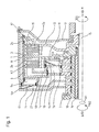
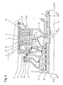
- FIG. 1 illustrates a possible basic structure and the operation of a dual clutch designed according to the invention with reference to a section of an exemplarily selected powertrain for a motor vehicle.
- crankshaft On the right side of the drawing figure can be connected via a spline, for example, a crankshaft to a clutch bell flange 12.
- the crankshaft is coupled to, for example, an internal combustion engine, a motor, or the like.
- This page represents the drive side of the powertrain.
- the first transmission input shaft (central or solid shaft 15) can be used for the operation of all odd gears (eg 1, 3, 5 %) and the second transmission input shaft (hollow shaft 16) for the operation of all even gears (eg. 2, 4, 6 ...) of the motor vehicle.
- the reverse gear could be assigned to both the first transmission input shaft (central or solid shaft 15), as well as the second transmission input shaft (hollow shaft 16) of the transmission.
- the dual clutch itself includes two single clutches K1 and K2.
- Each clutch K1, K2 each comprises an inner disk carrier 13, 14. Both clutches K1, K2 share a common outer disk carrier 6.
- the outer disk carrier of The first clutch K1 is hereinafter referred to as the first outer disk carrier 13
- the inner disk carrier of the second clutch K2 is hereinafter referred to as the second inner disk carrier 14.
- the first inner disk carrier 13 is rotatably connected via a spline with the solid shaft 15.
- the second inner disk carrier 14 is connected via a spline with the hollow shaft 16.
- the common outer disk carrier 6 is rotatably connected to a clutch hub 5 rotatably mounted about a rotatably mounted coupling carrier 10.
- This clutch hub 5 is in turn rotatably connected to the two clutches K1, K2 housing-like enclosing clutch bell 8, which in turn by means of a claw toothing rotatably connected to the aforementioned Kupplungsglockenflansch 12 and thus to the drive.
- the two inner disk carrier 13, 14 are half-shell-shaped and arranged axially adjacent to each other.
- the outer disk carrier 6 has a substantially cylindrical shape and extends over the axially extending portions of the half-shells 13, 14th
- the two inner disk carrier 13, 14 have external teeth, which serve for the axially displaceable but substantially non-rotatable guidance of in the present case in each case three corresponding internal gears having friction plates.
- the latter are also commonly referred to as inner disks.
- each pressure plates in the same manner as the above-mentioned outer disks are axially displaceable but guided substantially rotationally fixed.
- outer steel lamellae / outer lamellae, the inner friction lamellae / inner lamellae and the two pressure plates and the common back plate engage mutually in a manner known per se in a manner known per se, forming a lamella packet associated with a clutch K1, K2.
- the two disk packs with the corresponding steel / friction disks are thus arranged one behind the other on the common outer disk carrier 6 in the axial direction.
- the friction surfaces of all friction plates are substantially the same size, so that the individual clutches K1, K2 have an equivalent performance.
- the friction surfaces of the friction plates have different diameters.
- Each clutch K1, K2 is associated with a hydraulically actuated actuating piston 4a, 4b.
- Each of these actuating pistons 4a, 4b is provided for generating actuating forces actuating the respective clutches K1, K2. This means that starting from the respective force-generating actuating piston 4a, 4b corresponding pressure elements against the corresponding the two pressure plates are pressed, which press the respective associated plate packs against the common back plate frictional engagement between the adjacent steel / friction plates generating.
- the main feature of the invention is an outer sleeve carrier 6 outside embracing tension sleeve 1, which transmits tensile forces and compresses the "outer" lying plate set 2a for engaging.
- the disk packs 2a, 2b are arranged so that they can use a common back plate 3.
- the axial actuating forces act against each other and are supported against the common back plate from the third
- FIG. 1 The arrangement after FIG. 1 is particularly characterized in that the actuating piston 4a is arranged for the clutch K1 radially outward and thus the forces of the actuating piston 4a are guided very directly, resulting in a total of small deformations of the actuator.
- This piston 4a has a centrifugal force compensation by a compensation chamber 7a, which is formed by the clutch bell 8 and the actuating piston 4a itself.
- the second clutch K2 is actuated by the second actuating piston 4b, which in turn has a centrifugal force compensation.
- the required compensation chamber 7 b is formed by the piston 4 b and a hub cylinder 11.
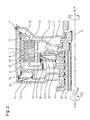
- FIG. 2 shows a second embodiment of a dual clutch according to the invention.
- This dual clutch has the essential components identical to the dual clutch according to the FIG. 1 on. To facilitate a reference, identical components are given the same reference numerals.
- FIG. 2 illustrated embodiment differs from that according to the FIG. 1 only by a changed coolant guide within the coupling device.
- an improved coolant supply of the first clutch K1 is ensured.
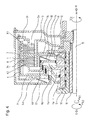
- FIG. 3 A third variant of a double clutch according to the invention is in the FIG. 3 shown. Also, this dual clutch has the essential components identical to the dual clutch according to the FIG. 1 on. To facilitate a reference, identical components are given the same reference numerals.
- the coupling system has the smallest possible diameter. Since for a given system pressure, the pistons 4a, 4b can not be arbitrarily small, they are here staggered axially one behind the other, wherein the flange 21 of the outer disk carrier 8 comes to rest between the two pressure chambers 9a, 9b. To avoid tumbling of the tension sleeve 1, this is at the outer end supported with a suitable (sliding) bearing element 24 against the outer disk carrier 6.
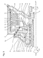
- FIG. 4 represents a further variant in which the components of the hydraulic actuation have been optimized in terms of the shortest possible axial length. Also, this dual clutch has the essential components identical to the dual clutch according to the FIG. 1 on. To facilitate a reference, identical components are given the same reference numerals.
- the pistons 4a, 4b are arranged nested within the inner disk carrier 14 in order to reduce the axial installation space.
- FIG. 5 This double clutch has the essential components identical to the double clutch according to the FIG. 1 on. To facilitate a reference, identical components are given the same reference numerals.
- This variant is a modification of the variant FIG. 3 , wherein the drive is done from the inside out. Since in this case no radially nested hollow shafts are required within the oil inlet, this design can be carried out in principle with a particularly small system diameter.
Landscapes
- Engineering & Computer Science (AREA)
- General Engineering & Computer Science (AREA)
- Mechanical Engineering (AREA)
- Hydraulic Clutches, Magnetic Clutches, Fluid Clutches, And Fluid Joints (AREA)
Claims (13)
- Double embrayage pour une boîte de vitesses comprenant deux arbres d'entrée de boite de vitesses (15, 16),- avec deux embrayages (K1, K2) disposés axialement l'un derrière l'autre et pouvant tourner autour d'un axe de rotation commun (ax) qui présentent- un porte-disques extérieur commun entraîné (6) et à chaque fois un porte-disques intérieur d'entraînement de sortie (13, 14),- une douille de traction (1) venant en prise autour du porte-disques extérieur (6) étant prévue, laquelle permet d'actionner l'un des deux embrayages (K1),- pour l'actionnement d'un embrayage (K1), un premier piston d'actionnement (4a) pouvant être actionné hydrauliquement par le biais d'une première chambre de pression (9a) étant prévu,- une première chambre de compensation (7a) pour la compensation de la force centrifuge pour le premier piston d'actionnement (4a) étant prévue, laquelle est formée par une cloche d'embrayage (8, 8') entraînée et le premier piston d'actionnement (4a),caractérisé en ce
qu'une deuxième chambre de compensation (7b) est prévue pour la compensation de la force centrifuge pour un deuxième piston d'actionnement (4b) pouvant être actionné hydrauliquement pour l'actionnement de l'autre embrayage (K2) par le biais d'une deuxième chambre de pression (9b), laquelle est formée par un cylindre de moyeu (11) et le deuxième piston d'actionnement (4b), et en ce que la cloche d'embrayage (8, 8'), le premier piston d'actionnement (4a), une bride du porte-disques extérieur (21) du porte-disques extérieur (6), le deuxième piston d'actionnement (4b) et le cylindre de moyeu (11) sont disposés de manière emboîtée. - Double embrayage selon la revendication 1,
caractérisé en ce que
la douille de traction (1) vient en prise par le dessus avec le porte-disques extérieur (6) sur toute sa longueur axiale. - Double embrayage selon la revendication 1 ou 2,
caractérisé en ce que
la douille de traction (1) est réalisée de manière complémentaire de par sa forme et sa fonction avec le contour extérieur du porte-disques extérieur (6), notamment présente une forme cylindrique circulaire. - Double embrayage selon l'une quelconque des revendications précédentes,
caractérisé en ce que
la douille de traction (1) présente des ouvertures conduisant essentiellement radialement vers l'extérieur. - Double embrayage selon l'une quelconque des revendications précédentes,
caractérisé en ce que
la douille de traction (1) est montée de manière déplaçable axialement sur le porte-disques extérieur (6). - Double embrayage selon l'une quelconque des revendications précédentes,
caractérisé en ce que
la douille de traction (1) transmet la force de traction lors de l'actionnement d'un embrayage (K1). - Double embrayage selon la revendication 6,
caractérisé en ce que
l'on prévoit un couvercle de douille de traction (19) qui est limité par une butée au moins dans la direction de l'axe de rotation (ax), afin d'amener les disques d'un embrayage (K1) en engagement de frottement. - Double embrayage selon l'une quelconque des revendications précédentes,
caractérisé en ce que
le premier piston d'actionnement (4a) est connecté à la douille de traction (1) au moins dans une direction de l'axe de rotation (ax) de manière limitée par une butée, de préférence solidaire en rotation, par exemple d'une seule pièce. - Double embrayage selon l'une quelconque des revendications précédentes,
caractérisé en ce que
le premier piston d'actionnement (4a) est disposé axialement à proximité de l'autre des deux embrayages (K2). - Double embrayage selon l'une quelconque des revendications précédentes,
caractérisé en ce que
la cloche d'embrayage (8, 8') vient en prise à la manière d'un pot par-dessus le premier piston d'actionnement (4a), en ce que le premier piston d'actionnement (4a) vient en prise à la manière d'un pot par-dessus la bride du porte-disques extérieur (21), en ce que la bride du porte-disques extérieur (21) vient en prise à la manière d'un pot par-dessus le deuxième piston d'actionnement (4b), et en ce que le deuxième piston d'actionnement (4b) vient en prise à la manière d'un pot par-dessus le cylindre de moyeu (11). - Double embrayage selon l'une quelconque des revendications précédentes,
caractérisé en ce que
le cylindre de moyeu (11) vient en prise à la manière d'un pot par-dessus le deuxième piston d'actionnement (4b), en ce que le deuxième piston d'actionnement (4b) vient en prise à la manière d'un pot par-dessus la bride du porte-disques extérieur (21), en ce que la bride du porte-disques extérieur (21) vient en prise à la manière d'un pot par-dessus le premier piston d'actionnement (4a) et en ce que le premier piston d'actionnement (4a) vient en prise à la manière d'un pot par-dessus la cloche d'embrayage (8, 8'). - Double embrayage selon l'une quelconque des revendications précédentes,
caractérisé en ce que
le premier piston d'actionnement (4a) et la première chambre de pression associée (9a) sont disposés dans la région radiale entre le contour extérieur de la douille de traction (1) et le contour extérieur du porte-disques intérieur (11, 13). - Double embrayage selon l'une quelconque des revendications précédentes,
caractérisé en ce que
l'on associe au premier piston d'actionnement (4a) et/ou au deuxième piston d'actionnement (4b) un élément de rappel, par exemple un ressort Belleville (17, 18).
Priority Applications (4)
| Application Number | Priority Date | Filing Date | Title |
|---|---|---|---|
| DE502004007383T DE502004007383D1 (de) | 2004-02-27 | 2004-02-27 | Doppelkupplung |
| EP04004484A EP1568906B1 (fr) | 2004-02-27 | 2004-02-27 | Embrayage double |
| JP2004350574A JP2005241000A (ja) | 2004-02-27 | 2004-12-03 | ダブルクラッチ |
| US11/060,645 US7249665B2 (en) | 2004-02-27 | 2005-02-17 | Double clutch |
Applications Claiming Priority (1)
| Application Number | Priority Date | Filing Date | Title |
|---|---|---|---|
| EP04004484A EP1568906B1 (fr) | 2004-02-27 | 2004-02-27 | Embrayage double |
Publications (2)
| Publication Number | Publication Date |
|---|---|
| EP1568906A1 EP1568906A1 (fr) | 2005-08-31 |
| EP1568906B1 true EP1568906B1 (fr) | 2008-06-18 |
Family
ID=34745920
Family Applications (1)
| Application Number | Title | Priority Date | Filing Date |
|---|---|---|---|
| EP04004484A Expired - Lifetime EP1568906B1 (fr) | 2004-02-27 | 2004-02-27 | Embrayage double |
Country Status (4)
| Country | Link |
|---|---|
| US (1) | US7249665B2 (fr) |
| EP (1) | EP1568906B1 (fr) |
| JP (1) | JP2005241000A (fr) |
| DE (1) | DE502004007383D1 (fr) |
Families Citing this family (41)
| Publication number | Priority date | Publication date | Assignee | Title |
|---|---|---|---|---|
| US7171867B2 (en) * | 2003-10-06 | 2007-02-06 | Borgwarner Inc. | Multi-clutch system with blended output system for powertrain transmissions |
| JP4333469B2 (ja) * | 2004-05-06 | 2009-09-16 | トヨタ自動車株式会社 | 自動変速機のクラッチ装置 |
| US7246692B2 (en) * | 2004-10-26 | 2007-07-24 | Borgwarner Inc. | Dual clutch mechanism for a transmission |
| US8714326B2 (en) * | 2005-05-17 | 2014-05-06 | Borgwarner Inc. | Dual clutch mechanism for a transmission |
| EP1726843B1 (fr) * | 2005-05-25 | 2018-04-04 | BorgWarner, Inc. | Ensemble embrayage |
| DE102005044227A1 (de) † | 2005-09-16 | 2007-03-29 | Zf Friedrichshafen Ag | Lamellen-Kupplungseinrichtung |
| JP4714549B2 (ja) * | 2005-10-11 | 2011-06-29 | いすゞ自動車株式会社 | 複式クラッチ装置 |
| DE502005005635D1 (de) * | 2005-10-20 | 2008-11-20 | Getrag Ford Transmissions Gmbh | Doppelkupplung |
| DE102007008946C5 (de) | 2006-02-27 | 2021-10-07 | Borgwarner Inc. | Mehrfachkupplung für ein Fahrzeug mit einem Hybridantrieb |
| DE102006010113C5 (de) * | 2006-02-28 | 2010-05-20 | Getrag Getriebe- Und Zahnradfabrik Hermann Hagenmeyer Gmbh & Cie Kg | Doppelkupplungsanordnung für ein Doppelkupplungsgetriebe |
| DE102006031788A1 (de) * | 2006-07-10 | 2008-01-17 | Zf Friedrichshafen Ag | Schaltelementanordnung |
| JP5165223B2 (ja) | 2006-09-29 | 2013-03-21 | 本田技研工業株式会社 | 自動二輪車 |
| DE102007024788A1 (de) * | 2007-02-08 | 2008-08-14 | Borgwarner Inc., Auburn Hills | Kupplungseinrichtung mit Befestigungsmittel zur Fixierung der Ausgangsnabe |
| US8967352B2 (en) * | 2007-03-30 | 2015-03-03 | Eaton Corporation | Low driven inertia dual clutch |
| DE102007022420A1 (de) * | 2007-05-10 | 2008-11-13 | Borgwarner Inc., Auburn Hills | Doppelkupplungsanordnung mit axial kurz bauender Schachtelung von Arbeits- und Ausgleichsraum |
| DE102007022421B4 (de) | 2007-05-10 | 2020-03-05 | Borgwarner Inc. | Kupplungssystem für Kraftfahrzeugantriebe |
| DE102007022419A1 (de) | 2007-05-10 | 2008-11-13 | Borgwarner Inc., Auburn Hills | Doppelwellenkupplungsanordnung mit integrierter Dichtungsfläche |
| DE102008045791B4 (de) * | 2007-11-11 | 2020-08-06 | Saic Motor Corp. Ltd. | Doppelkupplungsgetriebe und Verfahren zur Montage eines Doppelkupplungsgetriebes |
| DE102008031865A1 (de) * | 2008-02-15 | 2009-08-20 | Borgwarner Inc., Auburn Hills | Kupplungseinrichtung mit einer Welle und einem Nabenteil |
| DE102008016269B4 (de) * | 2008-03-29 | 2019-08-08 | Borgwarner Inc. | Betätigungskolben für eine Reibkupplung und Reibkupplung mit einem solchen Betätigungskolben |
| DE102008055681B4 (de) | 2008-10-28 | 2020-10-15 | Magna Pt B.V. & Co. Kg | Doppelkupplungsanordnung für ein Doppelkupplungsgetriebe |
| DE102008055682C5 (de) | 2008-10-28 | 2017-11-02 | Getrag Getriebe- Und Zahnradfabrik Hermann Hagenmeyer Gmbh & Cie Kg | Doppelkupplung mit stehendem Kolben und verbesserten Einrücklagern |
| JP2010133544A (ja) * | 2008-12-08 | 2010-06-17 | Toyota Motor Corp | 自動変速機のピストン装置 |
| GB2476983A (en) * | 2010-01-19 | 2011-07-20 | Gm Global Tech Operations Inc | Double clutch for vehicles |
| WO2011094223A1 (fr) | 2010-01-26 | 2011-08-04 | Martin Burgbacher | Ensemble engrenage pour véhicule automobile |
| GB2478354A (en) * | 2010-03-05 | 2011-09-07 | Gm Global Tech Operations Inc | Double clutch wear adjuster having a differentiator |
| DE102010034128A1 (de) | 2010-08-12 | 2012-02-16 | Borgwarner Inc. | Parallele Doppelkupplungseinrichtung |
| JP5747259B2 (ja) * | 2011-08-18 | 2015-07-08 | ピョン ファ バレオ カンパニー リミテッド | ドライダブルクラッチ |
| DE102011115286A1 (de) * | 2011-09-29 | 2013-04-04 | Borgwarner Inc. | Parallele Doppelkupplungseinrichtung |
| DE102012017951A1 (de) | 2011-11-10 | 2013-05-16 | Borgwarner Inc. | Betätigungselement zur Betätigung eines Lamellenpakets und parallele Doppelkupplungseinrichtung mit einem solchen Betätigungselement |
| DE102012218829B4 (de) | 2011-12-15 | 2021-11-11 | Schaeffler Technologies AG & Co. KG | Doppelkupplung und Verfahren zu deren Montage |
| DE102012024699A1 (de) * | 2012-01-13 | 2013-07-18 | Borgwarner Inc. | Kupplungsanordnung mit einer Doppelkupplungseinrichtung |
| DE112013004549A5 (de) * | 2012-09-19 | 2015-05-28 | Schaeffler Technologies AG & Co. KG | Deckelfester Ausrücker für eine Doppelkupplung |
| EP2762752B1 (fr) * | 2013-01-30 | 2017-06-21 | C.R.F. Società Consortile per Azioni | boîte de vitesses pour véhicule |
| JP6065231B2 (ja) * | 2014-01-28 | 2017-01-25 | マツダ株式会社 | パワートレイン構造 |
| BE1024240B1 (nl) * | 2016-05-27 | 2018-01-10 | Punch Powertrain Nv | Koppelingssysteem en actuatie daarvoor |
| CN106122308B (zh) * | 2016-07-05 | 2018-10-19 | 广州汽车集团股份有限公司 | 一种用于汽车混合动力变速器的离合器装置 |
| DE102016216722A1 (de) * | 2016-09-05 | 2018-03-08 | Volkswagen Aktiengesellschaft | Mehrfach-Kupplung für ein Kraftfahrzeug, insbesondere für einen Hybridantrieb eines Kraftfahrzeugs |
| DE102016217851A1 (de) * | 2016-09-19 | 2018-03-22 | Schaeffler Technologies AG & Co. KG | Doppelkupplung für ein Kraftfahrzeug |
| FR3060682B1 (fr) * | 2016-12-21 | 2019-05-17 | Valeo Embrayages | Porte-disques d'entree pour un double embrayage humide, mecanisme et systeme d'embrayage et chaine de transmission hybride integrant un tel porte-disques |
| DE102019116593A1 (de) * | 2019-03-20 | 2020-09-24 | Schaeffler Technologies AG & Co. KG | Mehrscheibenkupplung mit optimierter Verschiebereibung; Hybridmodul, Doppelkupplungseinrichtung sowie Antriebsstrang |
Family Cites Families (17)
| Publication number | Priority date | Publication date | Assignee | Title |
|---|---|---|---|---|
| DE1160308B (de) * | 1957-02-23 | 1963-12-27 | Daimler Benz Ag | Planetenraederwechselgetriebe, insbesondere fuer Kraftfahrzeuge |
| GB956219A (en) * | 1961-12-02 | 1964-04-22 | Daimler Benz Ag | Improvements in friction clutch arrangements comprising power means for the operation thereof |
| US4237749A (en) * | 1979-05-11 | 1980-12-09 | General Motors Corporation | Multi-speed power transmission |
| JPH0794856B2 (ja) * | 1985-12-16 | 1995-10-11 | アイシン・エィ・ダブリュ株式会社 | 自動変速機におけるクラツチ装置 |
| JP3193030B2 (ja) * | 1987-12-19 | 2001-07-30 | ルーク・ラメレン・ウント・クップルングスバウ・ゲゼルシヤフト・ミツト・ベシユレンクテル・ハフツング | クラッチユニット |
| DE3819702A1 (de) * | 1988-06-09 | 1989-12-14 | Porsche Ag | Hydraulisch betaetigte doppelkupplung fuer ein kraftfahrzeug |
| JP3354303B2 (ja) * | 1994-08-19 | 2002-12-09 | 本田技研工業株式会社 | タンデム型油圧クラッチ |
| JP3540481B2 (ja) * | 1996-01-12 | 2004-07-07 | ジヤトコ株式会社 | 自動変速機の油圧係合装置 |
| JPH1151081A (ja) * | 1997-08-04 | 1999-02-23 | Toyota Motor Corp | ピストン機構 |
| DE19833378A1 (de) * | 1998-07-24 | 1999-12-09 | Getrag Getriebe Zahnrad | Doppelkupplung |
| DE10004186B4 (de) * | 1999-09-30 | 2013-03-07 | Volkswagen Ag | Mehrfach-Kupplungseinrichtung |
| FR2814516B1 (fr) * | 2000-09-22 | 2003-05-02 | Valeo | Dispositif de transmission a engrenages, en particulier pour vehicule automobile |
| EP1195537B1 (fr) | 2000-10-05 | 2003-03-12 | Ford Global Technologies, Inc., A subsidiary of Ford Motor Company | Double embrayage pour une transmission avec deux arbres d'entrée |
| DE10131816A1 (de) * | 2001-06-30 | 2003-01-16 | Zahnradfabrik Friedrichshafen | Schaltelement-Baugruppe für ein Getriebe |
| DE10146606A1 (de) * | 2001-09-21 | 2003-04-10 | Zf Sachs Ag | Mehrfach-Kupplungseinrichtung mit axial nebeneinander angeordneten Lamellen-Kupplungsanordnungen |
| JP3614390B2 (ja) * | 2001-09-28 | 2005-01-26 | アイシン・エィ・ダブリュ株式会社 | 自動変速機のクラッチ装置 |
| JP3513135B2 (ja) * | 2001-11-26 | 2004-03-31 | 富士重工業株式会社 | 車両用変速装置 |
-
2004
- 2004-02-27 DE DE502004007383T patent/DE502004007383D1/de not_active Expired - Lifetime
- 2004-02-27 EP EP04004484A patent/EP1568906B1/fr not_active Expired - Lifetime
- 2004-12-03 JP JP2004350574A patent/JP2005241000A/ja active Pending
-
2005
- 2005-02-17 US US11/060,645 patent/US7249665B2/en not_active Expired - Lifetime
Also Published As
| Publication number | Publication date |
|---|---|
| DE502004007383D1 (de) | 2008-07-31 |
| EP1568906A1 (fr) | 2005-08-31 |
| US7249665B2 (en) | 2007-07-31 |
| US20050189195A1 (en) | 2005-09-01 |
| JP2005241000A (ja) | 2005-09-08 |
Similar Documents
| Publication | Publication Date | Title |
|---|---|---|
| EP1568906B1 (fr) | Embrayage double | |
| EP1522753B1 (fr) | Embrayage double hydraulique | |
| DE102007008946C5 (de) | Mehrfachkupplung für ein Fahrzeug mit einem Hybridantrieb | |
| EP3135522B1 (fr) | Module hybride et procédé permettant la transmission d'un couple dans une chaîne cinématique d'un véhicule automobile | |
| EP2153080B1 (fr) | Dispositif d'embrayage double avec element de guidage de piston | |
| EP3139053B1 (fr) | Double embrayage dote d'un piston vertical et de butees d'embrayage ameliorees | |
| DE102007003107B4 (de) | Dreifachkupplung für Hybridantrieb mit Doppelkupplungsgetriebe | |
| DE102011009419B4 (de) | Mehrfachkupplungseinrichtung und Antriebsstrang mit einer solchen Mehrfachkupplungseinrichtung | |
| EP3337995B1 (fr) | Dispositif d'embrayage pour motorisation hybride | |
| EP2732174B1 (fr) | Double embrayage | |
| DE102010054545A1 (de) | Drehmomentübertragungseinrichtung | |
| DE102009058264A1 (de) | Kuppelverfahren und -mechanismus für elektrisch verstellbare Getriebe | |
| DE102014221573A1 (de) | Mehrfachkupplung, insbesondere Doppelkupplung, Kupplungsdruckraum sowie Pendelmassenträger-Turbine-Kopplung | |
| DE102009050998A1 (de) | Doppelkupplung für ein automatisches oder automatisiertes Doppelkupplungsgetriebe | |
| DE102013216333A1 (de) | Mehrfachkupplungsvorrichtung, insbesondere Doppelkupplungsvorrichtung | |
| EP1726842B1 (fr) | Ensemble embrayage avec embrayages voisins dans le sens radial. | |
| DE102017216511A1 (de) | Drehmomentübertragungsvorrichtung für den Antriebsstrang eines Hybridfahrzeugs | |
| DE102015208369A1 (de) | Kupplungsanordnung | |
| DE102015213873A1 (de) | Axiale Lamellenkupplung | |
| WO2021098906A1 (fr) | Module hybride à embrayage de séparation qui est optimisé par rapport au frottement par déplacement | |
| DE102021134007B4 (de) | Hybridmodul mit rotorintegriertem Dämpfer, Antriebsstrang umfassend das Hybridmodul und System zum Aufbau des Hybridmoduls | |
| DE102021126008A1 (de) | Lamellenkupplung mit Sicherungselement zur Sicherung des Stütztrings eines Lamellenpakets | |
| EP4193075A1 (fr) | Embrayage de séparation actionné par milieu sous pression qui est normalement fermé, comprenant un dispositif d'actionnement qui tourne avec celui-ci et qui chevauche axialement un dispositif amortisseur | |
| EP2041444B1 (fr) | Embrayage à huile hydraulique | |
| EP4162169A1 (fr) | Embrayage à friction pour transmission d'un couple d'une manière par friction-complémentarité et par complémentarité de formes |
Legal Events
| Date | Code | Title | Description |
|---|---|---|---|
| PUAI | Public reference made under article 153(3) epc to a published international application that has entered the european phase |
Free format text: ORIGINAL CODE: 0009012 |
|
| AK | Designated contracting states |
Kind code of ref document: A1 Designated state(s): AT BE BG CH CY CZ DE DK EE ES FI FR GB GR HU IE IT LI LU MC NL PT RO SE SI SK TR |
|
| AX | Request for extension of the european patent |
Extension state: AL LT LV MK |
|
| RAP1 | Party data changed (applicant data changed or rights of an application transferred) |
Owner name: BORGWARNER INC. |
|
| 17P | Request for examination filed |
Effective date: 20050924 |
|
| AKX | Designation fees paid |
Designated state(s): DE FR GB IT |
|
| GRAP | Despatch of communication of intention to grant a patent |
Free format text: ORIGINAL CODE: EPIDOSNIGR1 |
|
| GRAS | Grant fee paid |
Free format text: ORIGINAL CODE: EPIDOSNIGR3 |
|
| GRAA | (expected) grant |
Free format text: ORIGINAL CODE: 0009210 |
|
| AK | Designated contracting states |
Kind code of ref document: B1 Designated state(s): DE FR GB IT |
|
| REG | Reference to a national code |
Ref country code: GB Ref legal event code: FG4D Free format text: NOT ENGLISH |
|
| REF | Corresponds to: |
Ref document number: 502004007383 Country of ref document: DE Date of ref document: 20080731 Kind code of ref document: P |
|
| PLBE | No opposition filed within time limit |
Free format text: ORIGINAL CODE: 0009261 |
|
| STAA | Information on the status of an ep patent application or granted ep patent |
Free format text: STATUS: NO OPPOSITION FILED WITHIN TIME LIMIT |
|
| 26N | No opposition filed |
Effective date: 20090319 |
|
| GBPC | Gb: european patent ceased through non-payment of renewal fee |
Effective date: 20090227 |
|
| PG25 | Lapsed in a contracting state [announced via postgrant information from national office to epo] |
Ref country code: GB Free format text: LAPSE BECAUSE OF NON-PAYMENT OF DUE FEES Effective date: 20090227 |
|
| REG | Reference to a national code |
Ref country code: FR Ref legal event code: PLFP Year of fee payment: 12 |
|
| PGFP | Annual fee paid to national office [announced via postgrant information from national office to epo] |
Ref country code: IT Payment date: 20150219 Year of fee payment: 12 |
|
| PGFP | Annual fee paid to national office [announced via postgrant information from national office to epo] |
Ref country code: FR Payment date: 20150126 Year of fee payment: 12 |
|
| REG | Reference to a national code |
Ref country code: FR Ref legal event code: ST Effective date: 20161028 |
|
| PG25 | Lapsed in a contracting state [announced via postgrant information from national office to epo] |
Ref country code: IT Free format text: LAPSE BECAUSE OF NON-PAYMENT OF DUE FEES Effective date: 20160227 |
|
| PG25 | Lapsed in a contracting state [announced via postgrant information from national office to epo] |
Ref country code: FR Free format text: LAPSE BECAUSE OF NON-PAYMENT OF DUE FEES Effective date: 20160229 |
|
| PGFP | Annual fee paid to national office [announced via postgrant information from national office to epo] |
Ref country code: DE Payment date: 20230111 Year of fee payment: 20 |
|
| P01 | Opt-out of the competence of the unified patent court (upc) registered |
Effective date: 20230327 |
|
| REG | Reference to a national code |
Ref country code: DE Ref legal event code: R071 Ref document number: 502004007383 Country of ref document: DE |