EP1568906B1 - Double clutch - Google Patents
Double clutch Download PDFInfo
- Publication number
- EP1568906B1 EP1568906B1 EP04004484A EP04004484A EP1568906B1 EP 1568906 B1 EP1568906 B1 EP 1568906B1 EP 04004484 A EP04004484 A EP 04004484A EP 04004484 A EP04004484 A EP 04004484A EP 1568906 B1 EP1568906 B1 EP 1568906B1
- Authority
- EP
- European Patent Office
- Prior art keywords
- actuating piston
- plate carrier
- dual clutch
- manner
- clutch according
- Prior art date
- Legal status (The legal status is an assumption and is not a legal conclusion. Google has not performed a legal analysis and makes no representation as to the accuracy of the status listed.)
- Expired - Lifetime
Links
- 230000009977 dual effect Effects 0.000 claims description 34
- 230000005540 biological transmission Effects 0.000 claims description 17
- 230000004323 axial length Effects 0.000 claims description 5
- 230000000295 complement effect Effects 0.000 claims description 2
- 230000008878 coupling Effects 0.000 description 10
- 238000010168 coupling process Methods 0.000 description 10
- 238000005859 coupling reaction Methods 0.000 description 10
- 238000005457 optimization Methods 0.000 description 8
- 229910000831 Steel Inorganic materials 0.000 description 4
- 239000002826 coolant Substances 0.000 description 4
- 239000007787 solid Substances 0.000 description 4
- 239000010959 steel Substances 0.000 description 4
- 239000000969 carrier Substances 0.000 description 2
- 239000012530 fluid Substances 0.000 description 2
- 238000009434 installation Methods 0.000 description 2
- 239000000463 material Substances 0.000 description 2
- 241000209035 Ilex Species 0.000 description 1
- 241000446313 Lamella Species 0.000 description 1
- 238000006243 chemical reaction Methods 0.000 description 1
- 210000000078 claw Anatomy 0.000 description 1
- 238000002485 combustion reaction Methods 0.000 description 1
- 238000010276 construction Methods 0.000 description 1
- 238000001816 cooling Methods 0.000 description 1
- 238000011161 development Methods 0.000 description 1
- 230000018109 developmental process Effects 0.000 description 1
- 230000000694 effects Effects 0.000 description 1
- 239000007788 liquid Substances 0.000 description 1
- 238000004519 manufacturing process Methods 0.000 description 1
- 230000013011 mating Effects 0.000 description 1
- 239000002184 metal Substances 0.000 description 1
- 230000004048 modification Effects 0.000 description 1
- 238000012986 modification Methods 0.000 description 1
- 230000003071 parasitic effect Effects 0.000 description 1
- 238000003825 pressing Methods 0.000 description 1
Images

Classifications
-
- F—MECHANICAL ENGINEERING; LIGHTING; HEATING; WEAPONS; BLASTING
- F16—ENGINEERING ELEMENTS AND UNITS; GENERAL MEASURES FOR PRODUCING AND MAINTAINING EFFECTIVE FUNCTIONING OF MACHINES OR INSTALLATIONS; THERMAL INSULATION IN GENERAL
- F16D—COUPLINGS FOR TRANSMITTING ROTATION; CLUTCHES; BRAKES
- F16D25/00—Fluid-actuated clutches
- F16D25/06—Fluid-actuated clutches in which the fluid actuates a piston incorporated in, i.e. rotating with the clutch
- F16D25/062—Fluid-actuated clutches in which the fluid actuates a piston incorporated in, i.e. rotating with the clutch the clutch having friction surfaces
- F16D25/063—Fluid-actuated clutches in which the fluid actuates a piston incorporated in, i.e. rotating with the clutch the clutch having friction surfaces with clutch members exclusively moving axially
- F16D25/0635—Fluid-actuated clutches in which the fluid actuates a piston incorporated in, i.e. rotating with the clutch the clutch having friction surfaces with clutch members exclusively moving axially with flat friction surfaces, e.g. discs
- F16D25/0638—Fluid-actuated clutches in which the fluid actuates a piston incorporated in, i.e. rotating with the clutch the clutch having friction surfaces with clutch members exclusively moving axially with flat friction surfaces, e.g. discs with more than two discs, e.g. multiple lamellae
-
- F—MECHANICAL ENGINEERING; LIGHTING; HEATING; WEAPONS; BLASTING
- F16—ENGINEERING ELEMENTS AND UNITS; GENERAL MEASURES FOR PRODUCING AND MAINTAINING EFFECTIVE FUNCTIONING OF MACHINES OR INSTALLATIONS; THERMAL INSULATION IN GENERAL
- F16D—COUPLINGS FOR TRANSMITTING ROTATION; CLUTCHES; BRAKES
- F16D21/00—Systems comprising a plurality of actuated clutches
- F16D21/02—Systems comprising a plurality of actuated clutches for interconnecting three or more shafts or other transmission members in different ways
- F16D21/06—Systems comprising a plurality of actuated clutches for interconnecting three or more shafts or other transmission members in different ways at least two driving shafts or two driven shafts being concentric
-
- F—MECHANICAL ENGINEERING; LIGHTING; HEATING; WEAPONS; BLASTING
- F16—ENGINEERING ELEMENTS AND UNITS; GENERAL MEASURES FOR PRODUCING AND MAINTAINING EFFECTIVE FUNCTIONING OF MACHINES OR INSTALLATIONS; THERMAL INSULATION IN GENERAL
- F16D—COUPLINGS FOR TRANSMITTING ROTATION; CLUTCHES; BRAKES
- F16D25/00—Fluid-actuated clutches
- F16D25/10—Clutch systems with a plurality of fluid-actuated clutches
-
- F—MECHANICAL ENGINEERING; LIGHTING; HEATING; WEAPONS; BLASTING
- F16—ENGINEERING ELEMENTS AND UNITS; GENERAL MEASURES FOR PRODUCING AND MAINTAINING EFFECTIVE FUNCTIONING OF MACHINES OR INSTALLATIONS; THERMAL INSULATION IN GENERAL
- F16D—COUPLINGS FOR TRANSMITTING ROTATION; CLUTCHES; BRAKES
- F16D21/00—Systems comprising a plurality of actuated clutches
- F16D21/02—Systems comprising a plurality of actuated clutches for interconnecting three or more shafts or other transmission members in different ways
- F16D21/06—Systems comprising a plurality of actuated clutches for interconnecting three or more shafts or other transmission members in different ways at least two driving shafts or two driven shafts being concentric
- F16D2021/0661—Hydraulically actuated multiple lamellae clutches
Definitions
- the invention relates to a double clutch according to the preamble of patent claim 1.
- Dual clutches for motor vehicles are classified according to the nature of their friction partners in dry or wet, i. cooled by liquid cooling medium, couplings. Furthermore, you can distinguish double clutches according to their arrangement. Especially with the wet double clutches, there is the radially nested design ("concentric arrangement”) and the axially successively arranged clutches ("parallel arrangement").
- the hydraulic actuator is quite complicated and expensive.
- the DE 198 33 376 A1 from which the invention proceeds, has a comparatively complicated lever linkage with a plurality of tie rods for the transmission of power from the annular piston to the disk pack.
- the object of the invention is to provide a dual clutch in parallel design, in particular for a motor vehicle, which is both simple in construction and allows easy synchronization of the gears of the motor vehicle and also has an optimized space requirement.
- a first via a first pressure chamber hydraulically actuated actuating piston is provided for actuating the one clutch.
- a first compensation space for centrifugal force compensation for the first actuating piston is provided, which is formed by a driven clutch bell and the first actuating piston.
- a second compensation chamber for centrifugal force compensation for a second for actuating the other clutch via a second pressure chamber hydraulically actuated actuating piston is provided, which is formed by a hub cylinder and the second actuating piston.
- the clutch bell, the first actuating piston, an outer disk carrier flange of the outer disk carrier, the second actuating piston and the hub cylinder are arranged nested.
- tension sleeve engages over the outer disk carrier over its entire axial length. This makes it possible, the actuating sleeve moving the pulling sleeve to arrange radially within the outer contour of the tension sleeve. The radial space can be kept small in this way.
- the tension sleeve shape and function complementary to the outer contour of the outer disk carrier, in particular circular cylindrical, is formed. It is only to ensure that a sufficient axial stroke is possible, which allows actuation of the corresponding clutch. In this way, the required radial space is reduced to the minimum required for the functionality of the coupling.
- the tension sleeve (as well as the outer disk carrier) has substantially radially outwardly leading openings. This measure allows efficient cooling of the friction (friction) blades by passing a corresponding fluid, e.g. Coolant, can be efficiently discharged radially outward.
- the invention provides that the tension sleeve is mounted axially displaceably on the outer disk carrier.
- a bearing may consist in one or more radial bearings, but it may also be one or more attached to the outer periphery of the outer disk carrier simple guide sleeves.
- the tension sleeve transmits pulling force when operating a clutch.
- An advantageous embodiment of this variant provides a Switzerlandhülsendeckel, which is limited stop at least in the direction of the axis of rotation to spend slats of a clutch in frictional engagement.
- a non-rotatable or even rigid connection between Wernersendeckel and tension sleeve is not mandatory, although conceivable.
- this embodiment with (one-sided or two-sided) axial impact has the advantage of a simple and thus cost-effective production and assembly.
- this invention is suitable both for use in dry clutches and wet-running multi-plate clutches.
- the required for actuating the coupling operative connection between the first actuating piston and the tension sleeve can be performed similar to that between the tension sleeve and Switzerlandhülsendeckel be.
- the actuating piston and the tension sleeve rotatably or even rigidly, for example in one piece, to connect with each other.
- the multi-part stop limited execution usually has advantages in terms of the complexity of the components (simple pressing parts) and the assembly (easy mating).
- the radial space can be kept small in particular by the fact that the first actuating piston is arranged axially adjacent to the other of the two clutches. If you want to keep the axial space as small as possible, so it offers a to the DE 198 33 376 A1 Approximated solution in which the actuating piston is arranged radially within the disk sets of the two clutches. Deviating from this embodiment described there, however, it is preferable to arrange the first actuating piston for the first clutch on the axially other side. This means for the case in which the first clutch is arranged to the right of the second clutch, that the actuating piston of the first clutch is to the left of the actuating piston of the second clutch.
- the clutch bell may be designed as a clutch bell in the conventional sense, which encloses the entire double clutch like a box. However, it is also possible that this is designed only as a cover-like flange part, as will be explained in detail in an exemplary embodiment.
- the invention ensures a switching of the two clutches of the double clutch, which takes place with defined contact force, even at high rotational speeds.
- a coupling system with a small diameter is obtained when the clutch bell cup-like overlaps the first actuating piston, when at the same time the first actuating piston cup-like overlaps the Jardinlamellenippoflansch, again at the same time the Jardinlamellennsch the second Actuating piston pot-like overlaps and when, at the same time, the second actuating piston cup-like overlaps the hub cylinder.
- a restoring element e.g. a diaphragm spring is assigned or are.
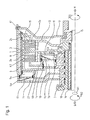
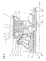
- FIG. 1 illustrates a possible basic structure and the operation of a dual clutch designed according to the invention with reference to a section of an exemplarily selected powertrain for a motor vehicle.
- crankshaft On the right side of the drawing figure can be connected via a spline, for example, a crankshaft to a clutch bell flange 12.
- the crankshaft is coupled to, for example, an internal combustion engine, a motor, or the like.
- This page represents the drive side of the powertrain.
- the first transmission input shaft (central or solid shaft 15) can be used for the operation of all odd gears (eg 1, 3, 5 %) and the second transmission input shaft (hollow shaft 16) for the operation of all even gears (eg. 2, 4, 6 ...) of the motor vehicle.
- the reverse gear could be assigned to both the first transmission input shaft (central or solid shaft 15), as well as the second transmission input shaft (hollow shaft 16) of the transmission.
- the dual clutch itself includes two single clutches K1 and K2.
- Each clutch K1, K2 each comprises an inner disk carrier 13, 14. Both clutches K1, K2 share a common outer disk carrier 6.
- the outer disk carrier of The first clutch K1 is hereinafter referred to as the first outer disk carrier 13
- the inner disk carrier of the second clutch K2 is hereinafter referred to as the second inner disk carrier 14.
- the first inner disk carrier 13 is rotatably connected via a spline with the solid shaft 15.
- the second inner disk carrier 14 is connected via a spline with the hollow shaft 16.
- the common outer disk carrier 6 is rotatably connected to a clutch hub 5 rotatably mounted about a rotatably mounted coupling carrier 10.
- This clutch hub 5 is in turn rotatably connected to the two clutches K1, K2 housing-like enclosing clutch bell 8, which in turn by means of a claw toothing rotatably connected to the aforementioned Kupplungsglockenflansch 12 and thus to the drive.
- the two inner disk carrier 13, 14 are half-shell-shaped and arranged axially adjacent to each other.
- the outer disk carrier 6 has a substantially cylindrical shape and extends over the axially extending portions of the half-shells 13, 14th
- the two inner disk carrier 13, 14 have external teeth, which serve for the axially displaceable but substantially non-rotatable guidance of in the present case in each case three corresponding internal gears having friction plates.
- the latter are also commonly referred to as inner disks.
- each pressure plates in the same manner as the above-mentioned outer disks are axially displaceable but guided substantially rotationally fixed.
- outer steel lamellae / outer lamellae, the inner friction lamellae / inner lamellae and the two pressure plates and the common back plate engage mutually in a manner known per se in a manner known per se, forming a lamella packet associated with a clutch K1, K2.
- the two disk packs with the corresponding steel / friction disks are thus arranged one behind the other on the common outer disk carrier 6 in the axial direction.
- the friction surfaces of all friction plates are substantially the same size, so that the individual clutches K1, K2 have an equivalent performance.
- the friction surfaces of the friction plates have different diameters.
- Each clutch K1, K2 is associated with a hydraulically actuated actuating piston 4a, 4b.
- Each of these actuating pistons 4a, 4b is provided for generating actuating forces actuating the respective clutches K1, K2. This means that starting from the respective force-generating actuating piston 4a, 4b corresponding pressure elements against the corresponding the two pressure plates are pressed, which press the respective associated plate packs against the common back plate frictional engagement between the adjacent steel / friction plates generating.
- the main feature of the invention is an outer sleeve carrier 6 outside embracing tension sleeve 1, which transmits tensile forces and compresses the "outer" lying plate set 2a for engaging.
- the disk packs 2a, 2b are arranged so that they can use a common back plate 3.
- the axial actuating forces act against each other and are supported against the common back plate from the third
- FIG. 1 The arrangement after FIG. 1 is particularly characterized in that the actuating piston 4a is arranged for the clutch K1 radially outward and thus the forces of the actuating piston 4a are guided very directly, resulting in a total of small deformations of the actuator.
- This piston 4a has a centrifugal force compensation by a compensation chamber 7a, which is formed by the clutch bell 8 and the actuating piston 4a itself.
- the second clutch K2 is actuated by the second actuating piston 4b, which in turn has a centrifugal force compensation.
- the required compensation chamber 7 b is formed by the piston 4 b and a hub cylinder 11.
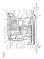
- FIG. 2 shows a second embodiment of a dual clutch according to the invention.
- This dual clutch has the essential components identical to the dual clutch according to the FIG. 1 on. To facilitate a reference, identical components are given the same reference numerals.
- FIG. 2 illustrated embodiment differs from that according to the FIG. 1 only by a changed coolant guide within the coupling device.
- an improved coolant supply of the first clutch K1 is ensured.
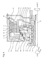
- FIG. 3 A third variant of a double clutch according to the invention is in the FIG. 3 shown. Also, this dual clutch has the essential components identical to the dual clutch according to the FIG. 1 on. To facilitate a reference, identical components are given the same reference numerals.
- the coupling system has the smallest possible diameter. Since for a given system pressure, the pistons 4a, 4b can not be arbitrarily small, they are here staggered axially one behind the other, wherein the flange 21 of the outer disk carrier 8 comes to rest between the two pressure chambers 9a, 9b. To avoid tumbling of the tension sleeve 1, this is at the outer end supported with a suitable (sliding) bearing element 24 against the outer disk carrier 6.
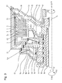
- FIG. 4 represents a further variant in which the components of the hydraulic actuation have been optimized in terms of the shortest possible axial length. Also, this dual clutch has the essential components identical to the dual clutch according to the FIG. 1 on. To facilitate a reference, identical components are given the same reference numerals.
- the pistons 4a, 4b are arranged nested within the inner disk carrier 14 in order to reduce the axial installation space.
- FIG. 5 This double clutch has the essential components identical to the double clutch according to the FIG. 1 on. To facilitate a reference, identical components are given the same reference numerals.
- This variant is a modification of the variant FIG. 3 , wherein the drive is done from the inside out. Since in this case no radially nested hollow shafts are required within the oil inlet, this design can be carried out in principle with a particularly small system diameter.
Landscapes
- Engineering & Computer Science (AREA)
- General Engineering & Computer Science (AREA)
- Mechanical Engineering (AREA)
- Hydraulic Clutches, Magnetic Clutches, Fluid Clutches, And Fluid Joints (AREA)
Description
Die Erfindung betrifft eine Doppelkupplung gemäß dem Oberbegriff des Patentanspruchs 1.The invention relates to a double clutch according to the preamble of
Doppelkupplungen für Kraftfahrzeuge werden unterschieden nach Art ihrer Reibpartner in trockene oder nasse, d.h. mittels flüssigem Kühlmedium gekühlte, Kupplungen. Ferner kann man Doppelkupplungen unterscheiden nach ihrer Anordnung. Insbesondere bei den nassen Doppelkupplungen gibt es die radial ineinander geschachtelte Bauart ("konzentrische Anordnung") und die axial hintereinander angeordneten Kupplungen ("parallele Anordnung").Dual clutches for motor vehicles are classified according to the nature of their friction partners in dry or wet, i. cooled by liquid cooling medium, couplings. Furthermore, you can distinguish double clutches according to their arrangement. Especially with the wet double clutches, there is the radially nested design ("concentric arrangement") and the axially successively arranged clutches ("parallel arrangement").
Bekannt sind nasse, parallele Kupplungen, bei denen der motorseitige Antrieb über die Innenlamellenträger erfolgt und der Abtrieb über die Außenlamellenträger. Eine derartige Ausführungsform entnimmt man beispielsweise der
Diese Bauart weist den Nachteil auf, dass die abtriebsseitigen Drehmassen durch die großen, zylinderförmigen Außenlamellenträger relativ groß sind. Dies führt zu Nachteilen bei der Synchronisierung der einzelnen Gänge.This design has the disadvantage that the output-side rotating masses are relatively large due to the large, cylindrical outer disk carrier. This leads to disadvantages in the synchronization of the individual gears.
Ebenfalls bekannt ist ferner eine Ausführung mittels Abtrieb über Innenlamellenträger. Beispiele derartiger Doppelkupplungen sind der
Bei beiden Ausführungsformen ist jedoch die hydraulische Betätigung recht kompliziert und aufwendig. Insbesondere die
Weitere Doppelkupplungen sind aus
Aufgabe der Erfindung ist es, eine Doppelkupplung in paralleler Bauart insbesondere für ein Kraftfahrzeug bereitzustellen, welche sowohl einfach aufgebaut ist als auch eine einfache Synchronisierung der Gänge des Kraftfahrzeugs erlaubt und zudem einen optimierten Bauraumbedarf besitzt.The object of the invention is to provide a dual clutch in parallel design, in particular for a motor vehicle, which is both simple in construction and allows easy synchronization of the gears of the motor vehicle and also has an optimized space requirement.
Diese Aufgabe wird durch eine Doppelkupplung mit den Merkmalen des Patentanspruchs 1 gelöst.This object is achieved by a double clutch with the features of
Vorteilhafte Ausführungen und Weiterbildungen der Erfindung sind in den Unteransprüchen angegeben.Advantageous embodiments and further developments of the invention are specified in the subclaims.
Erfindungsgemäß ist demnach bei einer Doppelkupplung in paralleler Anordnung mit angetriebenem Außenlamellenträger anstelle eines komplizierten Hebelgestänges mit Zuganker(n) eine den Außenlamellenträger umgreifende Zughülse vorgesehen, über die eine der beiden Kupplungen betätigbar ist. Auf diese Weise werden die Vorteile des Abtriebs über die Innenlamellenträger mit kleinem Massenträgheitsmoment mit einer einfachen hydraulischen Betätigung kombiniert.According to the invention in a double clutch in parallel arrangement with driven outer disk carrier instead of a complicated lever linkage with tie rod (s) a the outer disk carrier encompassing pulling sleeve is provided, via which one of the two clutches is actuated. In this way, the advantages of the output via the inner disk carrier with a small mass moment of inertia are combined with a simple hydraulic actuation.
Weiterhin ist zum Betätigen der einen Kupplung ein erster über einen ersten Druckraum hydraulisch betätigbarer Betätigungskolben vorgesehen.Furthermore, a first via a first pressure chamber hydraulically actuated actuating piston is provided for actuating the one clutch.
Zudem ist ein erster Ausgleichsraum zum Fliehkraftausgleich für den ersten Betätigungskolben vorgesehen, welcher durch eine angetriebene Kupplungsglocke und den ersten Betätigungskolben gebildet ist.In addition, a first compensation space for centrifugal force compensation for the first actuating piston is provided, which is formed by a driven clutch bell and the first actuating piston.
Weiterhin ist ein zweiter Ausgleichsraum zum Fliehkraftausgleich für einen zweiten zum Betätigen der anderen Kupplung über einen zweiten Druckraum hydraulisch betätigbaren Betätigungskolben vorgesehen, welcher durch einen Nabenzylinder und den zweiten Betätigungskolben gebildet ist.Furthermore, a second compensation chamber for centrifugal force compensation for a second for actuating the other clutch via a second pressure chamber hydraulically actuated actuating piston is provided, which is formed by a hub cylinder and the second actuating piston.
Des weiteren vorgesehen, dass die Kupplungsglocke, der erste Betätigungskolben, ein Außenlamellenträgerflansch des Außenlamellenträgers, der zweite Betätigungskolben und der Nabenzylinder geschachtelt angeordnet sind.It is further provided that the clutch bell, the first actuating piston, an outer disk carrier flange of the outer disk carrier, the second actuating piston and the hub cylinder are arranged nested.
Hierdurch wird das Verhältnis aus axialer Baulänge und radialem Bauraum des gesamten Kupplungssystems optimiert.As a result, the ratio of axial length and radial space of the entire coupling system is optimized.
Besonders vorteilhaft ist es, wenn die Zughülse den Außenlamellenträger über seiner gesamten axialen Länge übergreift. Damit wird es möglich, die die Zughülse bewegende Betätigungseinrichtung radial innerhalb der Außenkontur der Zughülse anzuordnen. Der radiale Bauraum kann auf diese Weise klein gehalten werden.It is particularly advantageous if the tension sleeve engages over the outer disk carrier over its entire axial length. This makes it possible, the actuating sleeve moving the pulling sleeve to arrange radially within the outer contour of the tension sleeve. The radial space can be kept small in this way.
Erfindungsgemäß ist weiter vorgesehen, dass die Zughülse form-und funktionskomplementär zur Außenkontur des Außenlamellenträgers, insbesondere kreiszylinderförmig, ausgebildet ist. Es ist lediglich sicherzustellen, dass ein ausreichender axialer Hub möglich ist, welcher ein Betätigen der entsprechenden Kupplung erlaubt. Auf diese Weise ist der benötigte radiale Bauraum auf das für die Funktionalität der Kupplung erforderliche Mindestmaß reduziert.According to the invention it is further provided that the tension sleeve shape and function complementary to the outer contour of the outer disk carrier, in particular circular cylindrical, is formed. It is only to ensure that a sufficient axial stroke is possible, which allows actuation of the corresponding clutch. In this way, the required radial space is reduced to the minimum required for the functionality of the coupling.
Es kann vorgesehen werden, dass die Zughülse (ebenso wie der Außenlamellenträger) im wesentlichen radial nach außen führende Öffnungen aufweist. Diese Maßnahme ermöglicht eine effiziente Kühlung der aneinander reibenden (Reib-)Lamellen, indem ein entsprechendes über die aneinander reibenden Flächen der Lamellen geführtes Fluid, z.B. Kühlflüssigkeit, effizient radial nach außen abgeführt werden kann.It can be provided that the tension sleeve (as well as the outer disk carrier) has substantially radially outwardly leading openings. This measure allows efficient cooling of the friction (friction) blades by passing a corresponding fluid, e.g. Coolant, can be efficiently discharged radially outward.
Weiter ist erfindungsgemäß vorgesehen, dass die Zughülse an dem Außenlamellenträger axial verschieblich gelagert ist. Eine derartige Lagerung kann in einer oder mehreren Radiallagern bestehen, es können jedoch auch eine oder mehrere am Außenumfang des Außenlamellenträgers angebrachte einfache Führungshülsen sein. Damit ist zum einen ein reibungsarmes Aneinandergleiten der korrespondierenden Flächen der Zughülse und des Außenlamellenträgers gewährleistet, zum anderen werden die beiden Bauteile, Zughülse und Außenlamellenträger, radial fixiert. Beide Effekte tragen zu einer geringen Verschleißneigung bei.Further, the invention provides that the tension sleeve is mounted axially displaceably on the outer disk carrier. Such a bearing may consist in one or more radial bearings, but it may also be one or more attached to the outer periphery of the outer disk carrier simple guide sleeves. Thus, on the one hand, a friction-poor sliding of the corresponding surfaces of the tension sleeve and the outer disk carrier is ensured, on the other hand, the two components, tension sleeve and outer disk carrier, radially fixed. Both effects contribute to a low tendency to wear.
Es ist erfindungsgemäß vorgesehen, dass die Zughülse beim Betätigen der einen Kupplung Zugkraft überträgt. Damit ist eine Anordnung der einzelnen Kupplungen der Doppelkupplung, wie sie in dem o.a. Dokument
Eine vorteilhafte Ausgestaltung dieser Variante sieht einen Zughülsendeckel vor, welcher wenigstens in Richtung der Drehachse anschlagbegrenzt ist, um Lamellen der einen Kupplung in Reibeingriff zu verbringen. Eine drehfeste oder gar starre Verbindung zwischen Zughülsendeckel und Zughülse ist nicht zwingend, wenngleich denkbar. Jedoch hat diese Ausführungsform mit (einseitiger oder beidseitiger) axialer Beanschlagung den Vorteil einer einfachen und damit kostengünstigen Herstellung sowie Montage.An advantageous embodiment of this variant provides a Zughülsendeckel, which is limited stop at least in the direction of the axis of rotation to spend slats of a clutch in frictional engagement. A non-rotatable or even rigid connection between Zughülsendeckel and tension sleeve is not mandatory, although conceivable. However, this embodiment with (one-sided or two-sided) axial impact has the advantage of a simple and thus cost-effective production and assembly.
Obigen Ausführungen ist zu entnehmen, dass sich diese Erfindung sowohl zum Einsatz bei Trockenkupplungen als auch bei nasslaufenden Lamellenkupplungen eignet.It can be seen from the above that this invention is suitable both for use in dry clutches and wet-running multi-plate clutches.
Die zum Betätigen der Kupplung erforderliche Wirkverbindung zwischen dem ersten Betätigungskolben und der Zughülse kann ähnlich wie die zwischen Zughülse und Zughülsendeckel ausgeführt sein. So kann der erste Betätigungskolben wenigstens in eine Richtung der Drehachse -nämlich in die zum Betätigen der Kupplung kraftübertragende Richtung- lediglich anschlagbegrenzt sein, es kann jedoch auch eine beidseitige axiale Fixierung vorgesehen werden. Je nach Anwendungsfall ist es erforderlich, den Betätigungskolben und die Zughülse drehfest oder gar starr, z.B. einstückig, miteinander zu verbinden. Die mehrteilige einseitig anschlagbegrenzte Ausführung hat jedoch in der Regel Vorteile in Bezug auf die Komplexität der Bauteile (einfache Preßteile) als auch der Montage (einfaches Zusammenstecken).The required for actuating the coupling operative connection between the first actuating piston and the tension sleeve can be performed similar to that between the tension sleeve and Zughülsendeckel be. Thus, the first actuating piston, at least in one direction of the axis of rotation-namely, in the force-transmitting direction for actuating the clutch-can be limited only by stops, but it is also possible to provide axial fixing on both sides. Depending on the application, it is necessary, the actuating piston and the tension sleeve rotatably or even rigidly, for example in one piece, to connect with each other. However, the multi-part stop limited execution usually has advantages in terms of the complexity of the components (simple pressing parts) and the assembly (easy mating).
Der radiale Bauraum lässt sich insbesondere dadurch klein halten, indem der erste Betätigungskolben axial benachbart zu der anderen der beiden Kupplungen angeordnet ist. Will man den axialen Bauraum möglichst gering halten, so bietet sich eine an die
Einen axial minimierten Bauraum erhalt man demzufolge dann wenn man den ersten Betätigungskolben innerhalb dem Lamellenpaket der zweiten Kupplung und den zweiten Betätigungskolben innerhalb dem Lamellenpaket der ersten Kupplung anordnet.An axially minimized installation space is therefore obtained if the first actuating piston within the disk set of the second clutch and the second actuating piston within the disk set of the first clutch are arranged.
Die Kupplungsglocke kann als Kupplungsglocke im herkömmlichen Sinn ausgestaltet sein, welche die gesamte Doppelkupplung gehäuseartig umgreift. Es ist jedoch auch möglich, dass diese lediglich als deckelartiges Flanschteil ausgeführt ist, wie nachfolgend in einem Ausführungsbeispiel noch eingehend erläutert wird.The clutch bell may be designed as a clutch bell in the conventional sense, which encloses the entire double clutch like a box. However, it is also possible that this is designed only as a cover-like flange part, as will be explained in detail in an exemplary embodiment.
Die Erfindung stellt ein mit definierter Anpresskraft erfolgendes Schalten der beiden Kupplungen der Doppelkupplung auch bei hohen Drehzahlen sicher.The invention ensures a switching of the two clutches of the double clutch, which takes place with defined contact force, even at high rotational speeds.
Ein Kupplungssystem mit geringem Durchmesser erhält man dann, wenn die Kupplungsglocke den ersten Betätigungskolben topfartig übergreift, wenn gleichzeitig der erste Betätigungskolben den Außenlamellenträgerflansch topfartig übergreift, wenn wiederum gleichzeitig der Außenlamellenträgerflansch den zweiten Betätigungskolben topfartig übergreift und wenn schließlich gleichzeitig der zweite Betätigungskolben den Nabenzylinder topfartig übergreift.A coupling system with a small diameter is obtained when the clutch bell cup-like overlaps the first actuating piston, when at the same time the first actuating piston cup-like overlaps the Außenlamellenträgerflansch, again at the same time the Außenlamellenträgerflansch the second Actuating piston pot-like overlaps and when, at the same time, the second actuating piston cup-like overlaps the hub cylinder.
Eine Optimierung auf möglichst kurze axiale Länge erhält man dann, wenn der Nabenzylinder den zweiten Betätigungskolben topfartig übergreift, wenn der zweite Betätigungskolben den Außenlamellenträgerflansch topfartig übergreift, wenn der Außenlamellenträgerflansch den ersten Betätigungskolben topfartig übergreift und wenn der erste Betätigungskolben die Kupplungsglocke topfartig übergreift.Optimization to the shortest possible axial length is obtained when the hub cylinder pot-like overlaps the second actuating piston when the second actuating piston cup-like overlaps the Außenlamellenträgerflansch when the Außenlamellenträgerflansch pot-like overlaps the first actuating piston and when the first actuating piston engages the clutch bell like a pot.
Eine Optimierung der Doppelkupplung hinsichtlich minimierter parasitären Kräfte erhält man dann, wenn der erste Betätigungskolben und der zugehörige erste Druckraum im radialen Bereich zwischen der Außenkontur der Zughülse und der Außenkontur der Innenlamellenträger angeordnet sind. Auf diese Weise werden die (Axial-) Kräfte des ersten Betätigungskolbens direkt geführt, was insgesamt zu kleinen Verformungen an der Betätigungseinrichtung, insbesondere der Zughülse, dem Betätigungskolben und dem Zughülsendeckel führt.An optimization of the dual clutch with respect to minimized parasitic forces is obtained when the first actuating piston and the associated first pressure chamber are arranged in the radial region between the outer contour of the tension sleeve and the outer contour of the inner disc carrier. In this way, the (axial) forces of the first actuating piston are guided directly, which leads to small overall deformations of the actuating device, in particular the tension sleeve, the actuating piston and the Zughülsendeckel.
Erfindungsgemäß ist weiter vorgesehen, dass dem ersten Betätigungskolben und/oder dem zweiten Betätigungskolben ein Rückstellelement, z.B. eine Tellerfeder zugeordnet ist bzw. sind. Mittels dieser Rückstellelemente werden die jeweiligen Betätigungskolben insbesondere im nicht hydraulikflüssigkeitsdruckbeaufschlagten Zustand in definierte Positionen verbracht.According to the invention it is further provided that the first actuating piston and / or the second actuating piston, a restoring element, e.g. a diaphragm spring is assigned or are. By means of these return elements, the respective actuating pistons are moved into defined positions, in particular in the non-hydraulic fluid pressurized state.
Die Erfindung wird nunmehr anhand der Zeichnung näher beschrieben. Es zeigen:
- Figur 1:
- ein erstes Ausführungsbeispiel einer erfindungsgemäßen Doppelkupplung im Axialhalbschnitt - Optimierung hinsichtlich kurzer Kraftwege, Antrieb von Außen -
- Figur 2:
- ein zweites Ausführungsbeispiel einer erfindungsgemäßen Doppelkupplung im Axialhalbschnitt - Optimierung hinsichtlich kurzer Kraftwege, Antrieb von Außen, modifizierte Ölführung -
- Figur 3:
- ein drittes Ausführungsbeispiel einer erfindungsgemäßen Doppelkupplung im Axialhalbschnitt - Optimierung hinsichtlich minimaler radialer Abmessungen, Antrieb von Außen -
- Figur 4:
- ein viertes Ausführungsbeispiel einer erfindungsgemäßen Doppelkupplung im Axialhalbschnitt - Optimierung hinsichtlich minimaler axialer Abmessungen, Antrieb von Außen -
- Figur 5:
- ein fünftes Ausführungsbeispiel einer erfindungsgemäßen Doppelkupplung im Axialhalbschnitt - Optimierung hinsichtlich minimaler radialer Abmessungen, Antrieb von Innen -
- Figur 6:
- ein sechstes Ausführungsbeispiel einer erfindungsgemäßen Doppelkupplung im Axialhalbschnitt - Optimierung hinsichtlich minimaler axialer Abmessungen, Antrieb von Außen, modifizierte Ölführung -
- FIG. 1:
- a first embodiment of a dual clutch according to the invention in the axial half section - optimization in terms of short power paths, drive from outside -
- FIG. 2:
- A second embodiment of a dual clutch according to the invention in the axial half section - Optimization in terms of short power paths, drive from the outside, modified oil guide -
- FIG. 3:
- A third embodiment of a dual clutch according to the invention in the axial half section - optimization in terms of minimum radial dimensions, drive from outside -
- FIG. 4:
- A fourth embodiment of a dual clutch according to the invention in the axial half section - optimization in terms of minimum axial dimensions, drive from outside -
- FIG. 5:
- A fifth embodiment of a dual clutch according to the invention in the axial half section - optimization in terms of minimum radial dimensions, drive from inside -
- FIG. 6:
- a sixth embodiment of a double clutch according to the invention in the axial half section - optimization in terms of minimum axial dimensions, drive from the outside, modified oil guide -
Die
Auf der rechten Seite der Zeichnungsfigur kann über eine Steckverzahnung beispielsweise eine Kurbelwelle an einen Kupplungsglockenflansch 12 angeschlossen werden. Die Kurbelwelle ist beispielsweise mit einer Verbrennungskraftmaschine, einem Motor oder dergleichen gekoppelt. Diese Seite stellt die Antriebsseite des Antriebsstrangs dar.On the right side of the drawing figure can be connected via a spline, for example, a crankshaft to a
Auf der linken Seite des Zeichnungsblattes sind zwei Getriebeeingangswellen, nämlich eine Zentral- oder Vollwelle 15 und eine Hohlwelle 16 zu sehen, welche aus der Kupplungsglocke 8 der Doppelkupplung herausgeführt sind und beispielsweise mit einem hier nicht dargestellten Getriebe oder dergleichen gekoppelt sind. Diese Seite stellt die Abtriebsseite des Antriebsstrangs dar.On the left side of the drawing sheet two transmission input shafts, namely a central or
So kann beispielsweise die erste Getriebeeingangswelle (Zentral- oder Vollwelle 15) zum Betrieb aller ungeraden Gänge (z. B. 1, 3, 5 ...) und die zweite Getriebeeingangswelle (Hohlwelle 16) zum Betrieb aller geraden Gänge (z. B. 2, 4, 6 ...) des Kraftfahrzeugs vorgesehen sein. Der Rückwärtsgang könnte sowohl der ersten Getriebeeingangswelle (Zentral- oder Vollwelle 15), als auch der zweiten Getriebeeingangswelle (Hohlwelle 16) des Getriebes zugeordnet sein.For example, the first transmission input shaft (central or solid shaft 15) can be used for the operation of all odd gears (
Die Doppelkupplung selbst umfasst zwei Einzelkupplungen K1 und K2. Jede Kupplung K1, K2 umfasst jeweils einen Innenlamellenträger 13, 14. Beide Kupplungen K1, K2 teilen sich einen gemeinsamen Außenlamellenträger 6. Der Außenenlamellenträger der ersten Kupplung K1 wird nachfolgend als erster Außenlamellenträger 13, der Innenlamellenträger der zweiten Kupplung K2 wird im Folgenden als zweiter Innenlamellenträger 14 bezeichnet.The dual clutch itself includes two single clutches K1 and K2. Each clutch K1, K2 each comprises an
Der erste Innenlamellenträger 13 ist über eine Steckverzahnung mit der Vollwelle 15 drehfest verbunden. Der zweite Innenlamellenträger 14 ist über eine Steckverzahnung mit der Hohlwelle 16 verbunden. Der gemeinsame Außenlamellenträger 6 ist drehfest mit einer um eine drehfest angeordnete Kupplungsträger 10 drehbar gelagerte Kupplungsnabe 5 verbunden. Diese Kupplungsnabe 5 ist wiederum drehfest mit einer die beiden Kupplungen K1, K2 gehäuseartig umgreifenden Kupplungsglocke 8 verbunden, welche wiederum mittels einer Klauenverzahnung drehfest mit dem vorerwähnten Kupplungsglockenflansch 12 und damit mit dem Antrieb verbunden ist.The first
Die beiden Innenlamellenträger 13, 14 sind halbschalenförmig ausgebildet und axial nebeneinander angeordnet. Der Außenlamellenträger 6 weist eine im Wesentlichen zylinderförmige Gestalt auf und erstreckt sich über die axial verlaufenden Bereiche der Halbschalen 13, 14.The two
Die beiden Innenlamellenträger 13, 14 weisen Außenverzahnungen auf, welche zur axial verschieblichen aber im Wesentlichen drehfesten Führung von im vorliegenden Fall jeweils drei entsprechende Innenverzahnungen aufweisenden Reiblamellen dienen. Letztere werden üblicherweise auch als Innenlamellen bezeichnet.The two
In entsprechender Weise sind am Innenumfang der den jeweiligen Innenlamellenträgern 13, 14 zugeordneten Außenlamellenträgerabschnitten des gemeinsamen Außenlamellenträgers 6 Innenverzahnungen angeordnet, in denen Außenverzahnungen aufweisende Stahllamellen, die sogenannten Außenlamellen, axial verschieblich aber drehfest geführt sind. Die beiden Außenlamellenträgerabschnitte werden durch eine gemeinsame Rückenplatte 3 voneinander getrennt.In a corresponding manner are on the inner circumference of the respective
An den beiden äußeren Enden des gemeinsamen Außenlamellenträgers 6 sind jeweils Druckplatten in gleicher Weise wie die vorstehend genannten Außenlamellen axial verschieblich aber im Wesentlichen drehfest geführt.At the two outer ends of the common
Die äußeren Stahllamellen/Außenlamellen, die inneren Reiblamellen/Innenlamellen sowie die beiden Druckplatten und die gemeinsame Rückenplatte greifen wechselseitig verzahnungsartig in an sich bekannter Weise jeweils ein einer Kupplung K1, K2 zugeordnetes Lamellenpaket bildend ineinander.The outer steel lamellae / outer lamellae, the inner friction lamellae / inner lamellae and the two pressure plates and the common back plate engage mutually in a manner known per se in a manner known per se, forming a lamella packet associated with a clutch K1, K2.
Die beiden Lamellenpakete mit den entsprechenden Stahl-/Reiblamellen sind somit auf dem gemeinsamen Außenlamellenträger 6 in axialer Richtung hintereinanderliegend angeordnet. Im vorliegenden Ausführungsbeispiel sind die Reibflächen aller Reiblamellen im Wesentlichen gleich groß, sodass die einzelnen Kupplungen K1, K2 eine gleichwertige Leistungsfähigkeit aufweisen. Selbstverständlich ist es auch möglich, dass die Reibflächen der Reiblamellen verschieden große Durchmesser aufweisen.The two disk packs with the corresponding steel / friction disks are thus arranged one behind the other on the common
Jeder Kupplung K1, K2 ist ein hydraulisch betätigbarer Betätigungskolben 4a, 4b zugeordnet. Jeder dieser Betätigungskolben 4a, 4b ist zur Erzeugung von die jeweiligen Kupplungen K1, K2 betätigenden Betätigungskräften vorgesehen. Das bedeutet, dass ausgehend von dem jeweiligen krafterzeugenden Betätigungskolben 4a, 4b entsprechende Druckelemente gegen die korrespondierende der beiden Druckplatten gedrückt werden, welche die jeweiligen zugeordneten Lamellenpakete gegen die gemeinsame Rückenplatte Reibschluss zwischen den benachbarten Stahl-/Reiblamellen erzeugend drücken.Each clutch K1, K2 is associated with a hydraulically actuated
Vorliegend werden die beiden Kupplungen K1, K2 nach innen gerichtet betätigt, wobei die Reaktionskräfte gegen die gemeinsame Rückenplatte 3 wirken.In the present case, the two clutches K1, K2 are actuated inwardly, the reaction forces acting against the
Hauptmerkmal der Erfindung ist eine den Außenlamellenträger 6 außen umgreifende Zughülse 1, welche Zugkräfte überträgt und das "außen" liegende Lamellenpaket 2a zum Einkuppeln zusammenpresst. Die Lamellenpakete 2a, 2b sind so angeordnet, dass sie eine gemeinsame Rückenplatte 3 benutzen können. Die axialen Betätigungskräfte wirken gegeneinander und stützen sich gegen die gemeinsame Rückenplatte ab 3.The main feature of the invention is an
Die Anordnung nach
Dieser Kolben 4a hat einen Fliehkraftausgleich durch einen Ausgleichsraum 7a, der gebildet wird durch die Kupplungsglocke 8 und den Betätigungskolben 4a selbst.This
Die zweite Kupplung K2 wird durch den zweiten Betätigungskolben 4b betätigt, der seinerseits einen Fliehkraftausgleich besitzt. Der benötigte Ausgleichsraum 7b wird gebildet durch den Kolben 4b und einen Nabenzylinder 11.The second clutch K2 is actuated by the
Die in
Die in
Eine dritte Variante einer erfindungsgemäßen Doppelkupplung ist in der
Hier wird besonderes Augenmerk darauf gerichtet, dass das Kupplungssystem einen möglichst kleinen Durchmesser aufweist. Da bei gegebenem Systemdruck die Kolben 4a, 4b nicht beliebig klein sein können, werden sie hier axial hintereinander gestaffelt, wobei der Flansch 21 des Außenlamellenträgers 8 zwischen den beiden Druckräumen 9a, 9b zu liegen kommt. Um ein Taumeln der Zughülse 1 zu vermeiden, ist diese am äußeren Ende mit einem geeigneten (Gleit-)Lagerelement 24 gegen den Außenlamellenträger 6 abgestützt.Here, special attention is paid to the fact that the coupling system has the smallest possible diameter. Since for a given system pressure, the
Die Kolben 4a, 4b werden zur Reduzierung des axialen Bauraums innerhalb des Innenlamellenträgers 14 geschachtelt angeordnet.The
Eine weitere Variante stellt
Diese Variante ist eine Abwandlung der Variante aus
Die dargestellten Ausführungen betreffen bisher den sogenannten "stehenden Support", bei der die Öleinführung über ein mit dem Getriebegehäuse verbundenen Kupplungsträger 10 ("Support") erfolgt. Es ist natürlich auch möglich, diese Kupplung mit "drehender Öleinführung" zu gestalten. Dies wird in
Alle vorstehend beschriebenen Ausführungsvarianten zeichnen sich durch folgende Vorteile aus:
- Drehzahlfestigkeit: Die Umfangsspannungen aufgrund der Eigenmasse einer dünnen Hülse hängen quadratisch ab von Radius und Drehzahl gemäß der Formel

- Die "Zughülse" kann als Blechteil mit geringer Wandstärke ausgeführt sein, da lediglich Zugspannungen wirken aus der Zugkraft selbst sowie der überlagerten Umfangsspannung aufgrund von Fliehkrafteinflüssen.
- Kleiner Durchmesser: Die Doppelkupplung kann mit relativ kleinem Durchmesser gebaut werden, da die Betätigungsvorrichtungen auf einer Seite angeordnet werden können und alleine die Lamellendurchmesser Durchmesser bestimmend sind (vgl.
Figur 3 ). - Kurze Baulänge: Es ist andererseits aber auch möglich, dieses Konzept im Hinblick auf kurze Baulänge zu optimieren, wobei sich die Betätigungsvorrichtungen dabei - zumindest teilweise - radial innerhalb der Lamellen befinden. Die andere Betätigungsvorrichtung kann hierbei auch außen etwa auf dem Radius der Lamellen vorgesehen werden (
Figur 1Figur 4 ).
- Speed resistance: The circumferential stresses due to the net mass of a thin sleeve depend quadratically on the radius and speed according to the formula
- The "tension sleeve" can be designed as a sheet metal part with a small wall thickness, since only tensile stresses act on the tensile force itself and the superimposed hoop stress due to centrifugal forces.
- Small diameter : The double clutch can be built with a relatively small diameter, since the actuators can be arranged on one side and only the diameter of the fins diameter determining (see.
FIG. 3 ). - Short overall length : On the other hand, it is also possible to optimize this concept with regard to short overall length, wherein the actuating devices are - at least partially - located radially inside the slats. The other actuator can also be provided outside on the radius of the slats (
FIG. 1 .FIG. 4 ).
- 11
- Zughülsepulling sleeve
- 2a2a
- Lamellenpaketdisk pack
- 2b2 B
- Lamellenpaketdisk pack
- 33
- gemeinsame Rückenplattecommon back plate
- 4a4a
- Betätigungskolbenactuating piston
- 4b4b
- Betätigungskolbenactuating piston
- 55
- Kupplungsnabeclutch
- 66
- AußenlamellenträgerExternal disk carrier
- 7a7a
- Ausgleichsraumcompensation space
- 7b7b
- Ausgleichsraumcompensation space
- 88th
- KupplungsglockeKupplungsglocke
- 8'8th'
- KupplungsglockenflanschteilKupplungsglockenflanschteil
- 9a9a
- Druckraumpressure chamber
- 9b9b
- Druckraumpressure chamber
- 1010
- Kupplungsträgercoupling support
- 1111
- Nabenzylinderhub cylinder
- 1212
- KupplungsglockenflanschKupplungsglockenflansch
- 1313
- InnenlamellenträgerInner disk carrier
- 1414
- InnenlamellenträgerInner disk carrier
- 1515
- erste Getriebeeingangswellefirst transmission input shaft
- 1616
- zweite Getriebeeingangswellesecond transmission input shaft
- 1717
- Rückstellelement (Tellerfeder)Return element (disc spring)
- 1818
- Rückstellelement (Tellerfeder)Return element (disc spring)
- 1919
- ZughülsendeckelZughülsendeckel
- 2121
- AußenlamellenträgerflanschAußenlamellenträgerflansch
- 2424
- Lagerelementbearing element
- K1K1
- Kupplungclutch
- K2K2
- Kupplungclutch
- rr
- Radiusradius
- axax
- Drehachseaxis of rotation
- ωω
- Winkelgeschwindigkeitangular velocity
- ωE ω E
- Eingangswinkelgeschwindigkeit (Motor)Input angular velocity (motor)
- ωA1 ω A1
- Ausgangswinkelgeschwindigkeit (erste Getriebeeingangswelle)Initial angular velocity (first transmission input shaft)
- ωA2 ω A2
- Ausgangswinkelgeschwindigkeit (zweite Getriebeeingangswelle)Initial angular velocity (second transmission input shaft)
- σσ
- Umfangsspannunghoop stress
- ρρ
- WerkstoffdichteMaterial density
- MM
- Motorengine
- GG
- Getriebetransmission
Claims (13)
- Dual clutch for a transmission having two transmission input shafts (15, 16),- having two clutches (K1, K2) which are rotatable about a common rotational axis (ax) and which are arranged axially in series and which- have a common driven outer plate carrier (6) and in each case one driving inner plate carrier (13, 14), with- a traction sleeve (1) which engages around the outer plate carrier (6) being provided, by means of which traction sleeve (1) the one of the two clutches (K1) can be actuated,- a first actuating piston (4a), which can be hydraulically actuated by means of a first pressure space (9a), being provided for actuating the one clutch (K1),- a first compensating space (7a) for centrifugal force compensation being provided for the first actuating piston (4a), which first compensating space (7a) is formed by a driven clutch bell (8, 8') and the first actuating piston (4a),characterized in that a second compensating space (7b) for centrifugal force compensation for a second actuating piston (4b) which can be hydraulically actuated by means of a second pressure space (9b) in order to actuate the other clutch (K2) is provided, which second compensating space (7b) is formed by a hub cylinder (11) and the second actuating piston (4b), and in that the clutch bell (8, 8'), the first actuating piston (4a), an outer plate carrier flange (21) of the outer plate carrier (6), the second actuating piston (4b) and the hub cylinder (11) are arranged in a nested fashion.
- Dual clutch according to Claim 1,
characterized in that
the traction sleeve (1) engages over the outer plate carrier (6) over its entire axial length. - Dual clutch according to Claim 1 or 2,
characterized in that
the traction sleeve (1) is of complementary design, in terms of shape and function, to the outer contour of the outer plate carrier (6), and is in particular of round cylindrical design. - Dual clutch according to one of the preceding claims,
characterized in that the traction sleeve (1) has openings which lead substantially radially outwards. - Dual clutch according to one of the preceding claims,
characterized in that the traction sleeve (1) is mounted in an axially movable manner on the outer plate carrier (6). - Dual clutch according to one of the preceding claims,
characterized in that the traction sleeve (1) transmits a tensile force during the actuation of the one clutch (K1). - Dual clutch according to Claim 6,
characterized in that a traction sleeve cover (19) is provided, which traction sleeve cover (19) is stop-limited at least in the direction of the rotational axis (ax) in order to place plates of the one clutch (K1) into frictional engagement. - Dual clutch according to one of the preceding claims,
characterized in that the first actuating piston (4a) is connected to the traction sleeve (1) in a stop-limited manner at least in one direction of the rotational axis (ax), preferably in a rotationally fixed manner, for example in one piece. - Dual clutch according to one of the preceding claims,
characterized in that the first actuating piston (4a) is arranged axially adjacent to the other of the two clutches (K2). - Dual clutch according to one of the preceding claims,
characterized in that the clutch bell (B, 8') engages over the first actuating piston (4a) in the manner of a pot, in that the first actuating piston (4a) engages over the outer plate carrier flange (21) in the manner of a pot, in that the outer plate carrier flange (21) engages over the second actuating piston (4b) in the manner of a pot, and in that the second actuating piston engages over the hub cylinder (11) in the manner of a pot. - Dual clutch according to one of the preceding claims,
characterized in that the hub cylinder (11) engages over the second actuating piston (4b) in the manner of a pot, in that the second actuating piston (4b) engages over the outer plate carrier flange (21) in the manner of a pot, in that the outer plate carrier flange (21) engages over the first actuating piston (4a) in the manner of a pot, and in that the first actuating piston (4a) engages over the clutch bell (8, 8') in the manner of a pot. - Dual clutch according to one of the preceding claims,
characterized in that the first actuating piston (4a) and the associated first pressure space (9a) are arranged in the radial region between the outer contour of the traction sleeve (1) and the outer contour of the inner plate carrier (11, 13). - Dual clutch according to one of the preceding claims,
characterized in that the first actuating piston (4a) and/or the second actuating piston (4b) are or is assigned a restoring element, for example a plate spring (17, 18).
Priority Applications (4)
| Application Number | Priority Date | Filing Date | Title |
|---|---|---|---|
| DE502004007383T DE502004007383D1 (en) | 2004-02-27 | 2004-02-27 | Double coupling |
| EP04004484A EP1568906B1 (en) | 2004-02-27 | 2004-02-27 | Double clutch |
| JP2004350574A JP2005241000A (en) | 2004-02-27 | 2004-12-03 | Double clutch |
| US11/060,645 US7249665B2 (en) | 2004-02-27 | 2005-02-17 | Double clutch |
Applications Claiming Priority (1)
| Application Number | Priority Date | Filing Date | Title |
|---|---|---|---|
| EP04004484A EP1568906B1 (en) | 2004-02-27 | 2004-02-27 | Double clutch |
Publications (2)
| Publication Number | Publication Date |
|---|---|
| EP1568906A1 EP1568906A1 (en) | 2005-08-31 |
| EP1568906B1 true EP1568906B1 (en) | 2008-06-18 |
Family
ID=34745920
Family Applications (1)
| Application Number | Title | Priority Date | Filing Date |
|---|---|---|---|
| EP04004484A Expired - Lifetime EP1568906B1 (en) | 2004-02-27 | 2004-02-27 | Double clutch |
Country Status (4)
| Country | Link |
|---|---|
| US (1) | US7249665B2 (en) |
| EP (1) | EP1568906B1 (en) |
| JP (1) | JP2005241000A (en) |
| DE (1) | DE502004007383D1 (en) |
Families Citing this family (41)
| Publication number | Priority date | Publication date | Assignee | Title |
|---|---|---|---|---|
| US7171867B2 (en) * | 2003-10-06 | 2007-02-06 | Borgwarner Inc. | Multi-clutch system with blended output system for powertrain transmissions |
| JP4333469B2 (en) * | 2004-05-06 | 2009-09-16 | トヨタ自動車株式会社 | Automatic transmission clutch device |
| US7246692B2 (en) * | 2004-10-26 | 2007-07-24 | Borgwarner Inc. | Dual clutch mechanism for a transmission |
| JP5159613B2 (en) * | 2005-05-17 | 2013-03-06 | ボーグワーナー インコーポレーテッド | Dual clutch mechanism for transmission |
| EP1726843B1 (en) * | 2005-05-25 | 2018-04-04 | BorgWarner, Inc. | Clutch assembly |
| DE102005044227A1 (en) † | 2005-09-16 | 2007-03-29 | Zf Friedrichshafen Ag | Multi-plate clutch device |
| JP4714549B2 (en) * | 2005-10-11 | 2011-06-29 | いすゞ自動車株式会社 | Double clutch device |
| DE502005005635D1 (en) * | 2005-10-20 | 2008-11-20 | Getrag Ford Transmissions Gmbh | Double coupling |
| DE102007008946C5 (en) | 2006-02-27 | 2021-10-07 | Borgwarner Inc. | Multiple clutch for a vehicle with a hybrid drive |
| DE102006010113C5 (en) * | 2006-02-28 | 2010-05-20 | Getrag Getriebe- Und Zahnradfabrik Hermann Hagenmeyer Gmbh & Cie Kg | Dual clutch arrangement for a dual-clutch transmission |
| DE102006031788A1 (en) * | 2006-07-10 | 2008-01-17 | Zf Friedrichshafen Ag | Switching element arrangement |
| JP5165223B2 (en) | 2006-09-29 | 2013-03-21 | 本田技研工業株式会社 | Motorcycle |
| DE102007024788A1 (en) * | 2007-02-08 | 2008-08-14 | Borgwarner Inc., Auburn Hills | Coupling device with fastening means for fixing the output hub |
| US8967352B2 (en) * | 2007-03-30 | 2015-03-03 | Eaton Corporation | Low driven inertia dual clutch |
| DE102007022421B4 (en) | 2007-05-10 | 2020-03-05 | Borgwarner Inc. | Coupling system for motor vehicle drives |
| DE102007022420A1 (en) | 2007-05-10 | 2008-11-13 | Borgwarner Inc., Auburn Hills | Double clutch arrangement with axially short nesting of working and compensation chamber |
| DE102007022419A1 (en) | 2007-05-10 | 2008-11-13 | Borgwarner Inc., Auburn Hills | Twin-shaft clutch arrangement for motor vehicle transmission has clutch plate with cylindrical outer wall sector in region of assembly joint |
| DE102008045791B4 (en) * | 2007-11-11 | 2020-08-06 | Saic Motor Corp. Ltd. | Double clutch transmission and method for assembling a double clutch transmission |
| DE102008031865A1 (en) * | 2008-02-15 | 2009-08-20 | Borgwarner Inc., Auburn Hills | Coupling device with a shaft and a hub part |
| DE102008016269B4 (en) * | 2008-03-29 | 2019-08-08 | Borgwarner Inc. | Actuating piston for a friction clutch and friction clutch with such an actuating piston |
| DE102008055681B4 (en) | 2008-10-28 | 2020-10-15 | Magna Pt B.V. & Co. Kg | Double clutch arrangement for a double clutch transmission |
| DE102008055682C5 (en) | 2008-10-28 | 2017-11-02 | Getrag Getriebe- Und Zahnradfabrik Hermann Hagenmeyer Gmbh & Cie Kg | Double clutch with upright piston and improved engagement bearings |
| JP2010133544A (en) * | 2008-12-08 | 2010-06-17 | Toyota Motor Corp | Piston unit for automatic transmission |
| GB2476983A (en) * | 2010-01-19 | 2011-07-20 | Gm Global Tech Operations Inc | Double clutch for vehicles |
| US8790211B2 (en) * | 2010-01-26 | 2014-07-29 | GKN Driveline Newton, LLC | Gear assembly for motor vehicle |
| GB2478354A (en) * | 2010-03-05 | 2011-09-07 | Gm Global Tech Operations Inc | Double clutch wear adjuster having a differentiator |
| DE102010034128A1 (en) | 2010-08-12 | 2012-02-16 | Borgwarner Inc. | Parallel double clutch device |
| CN103842677B (en) * | 2011-08-18 | 2016-05-11 | 平和法雷奥有限公司 | Dry dual clutch |
| DE102011115286A1 (en) * | 2011-09-29 | 2013-04-04 | Borgwarner Inc. | Parallel double clutch device |
| DE102012017951A1 (en) | 2011-11-10 | 2013-05-16 | Borgwarner Inc. | Operating element e.g. metal sheet part, for operating lamella packet of disk clutch of parallel wet dual clutch device of motor car, has pressing part fastened in mounting position at free ends of axial finger in detachable manner |
| DE102012218829B4 (en) | 2011-12-15 | 2021-11-11 | Schaeffler Technologies AG & Co. KG | Double clutch and method of assembling it |
| DE102012024699A1 (en) * | 2012-01-13 | 2013-07-18 | Borgwarner Inc. | Coupling arrangement for use in between drive unit and transmission in drive train of motor vehicle, has dual clutch unit with multi-disk clutches assigned to transmission input shafts, where multi-disk clutches have common input side |
| DE102013218112A1 (en) * | 2012-09-19 | 2014-03-20 | Schaeffler Technologies AG & Co. KG | Lid-proof release for a double clutch |
| EP2762752B1 (en) * | 2013-01-30 | 2017-06-21 | C.R.F. Società Consortile per Azioni | A gearbox for a motor vehicle |
| JP6065231B2 (en) * | 2014-01-28 | 2017-01-25 | マツダ株式会社 | Powertrain structure |
| BE1024240B1 (en) | 2016-05-27 | 2018-01-10 | Punch Powertrain Nv | COUPLING SYSTEM AND ACTUATION THEREFORE |
| CN106122308B (en) * | 2016-07-05 | 2018-10-19 | 广州汽车集团股份有限公司 | A kind of clutch apparatus for automobile hybrid power speed changer |
| DE102016216722A1 (en) * | 2016-09-05 | 2018-03-08 | Volkswagen Aktiengesellschaft | Multiple clutch for a motor vehicle, in particular for a hybrid drive of a motor vehicle |
| DE102016217851A1 (en) * | 2016-09-19 | 2018-03-22 | Schaeffler Technologies AG & Co. KG | Double clutch for a motor vehicle |
| FR3060682B1 (en) * | 2016-12-21 | 2019-05-17 | Valeo Embrayages | INTAKE DISC TRAYS FOR A DUAL WET CLUTCH, MECHANISM AND CLUTCH SYSTEM, AND HYBRID TRANSMISSION CHAIN INCORPORATING SUCH A DISK HOLDER |
| DE102019116593A1 (en) * | 2019-03-20 | 2020-09-24 | Schaeffler Technologies AG & Co. KG | Multi-plate clutch with optimized sliding friction; Hybrid module, double clutch device and drive train |
Family Cites Families (17)
| Publication number | Priority date | Publication date | Assignee | Title |
|---|---|---|---|---|
| DE1160308B (en) * | 1957-02-23 | 1963-12-27 | Daimler Benz Ag | Planetary change gear, especially for motor vehicles |
| GB956219A (en) * | 1961-12-02 | 1964-04-22 | Daimler Benz Ag | Improvements in friction clutch arrangements comprising power means for the operation thereof |
| US4237749A (en) * | 1979-05-11 | 1980-12-09 | General Motors Corporation | Multi-speed power transmission |
| JPH0794856B2 (en) * | 1985-12-16 | 1995-10-11 | アイシン・エィ・ダブリュ株式会社 | Clutch device for automatic transmission |
| JP3193030B2 (en) * | 1987-12-19 | 2001-07-30 | ルーク・ラメレン・ウント・クップルングスバウ・ゲゼルシヤフト・ミツト・ベシユレンクテル・ハフツング | Clutch unit |
| DE3819702A1 (en) * | 1988-06-09 | 1989-12-14 | Porsche Ag | HYDRAULICALLY OPERATED DOUBLE CLUTCH FOR A MOTOR VEHICLE |
| JP3354303B2 (en) * | 1994-08-19 | 2002-12-09 | 本田技研工業株式会社 | Tandem hydraulic clutch |
| JP3540481B2 (en) * | 1996-01-12 | 2004-07-07 | ジヤトコ株式会社 | Hydraulic engagement device for automatic transmission |
| JPH1151081A (en) * | 1997-08-04 | 1999-02-23 | Toyota Motor Corp | Piston mechanism |
| DE19833378A1 (en) * | 1998-07-24 | 1999-12-09 | Getrag Getriebe Zahnrad | Double clutch arrangement reduces the level of friction |
| DE10004186B4 (en) * | 1999-09-30 | 2013-03-07 | Volkswagen Ag | Multiple clutch device |
| FR2814516B1 (en) * | 2000-09-22 | 2003-05-02 | Valeo | GEAR TRANSMISSION DEVICE, ESPECIALLY FOR A MOTOR VEHICLE |
| DE50001452D1 (en) * | 2000-10-05 | 2003-04-17 | Ford Global Tech Inc | Double clutch for a transmission with two transmission input shafts |
| DE10131816A1 (en) * | 2001-06-30 | 2003-01-16 | Zahnradfabrik Friedrichshafen | Switching element assembly for a transmission |
| DE10146606A1 (en) * | 2001-09-21 | 2003-04-10 | Zf Sachs Ag | Multiple clutch device with axially adjacent multi-plate clutch arrangements |
| JP3614390B2 (en) * | 2001-09-28 | 2005-01-26 | アイシン・エィ・ダブリュ株式会社 | Automatic transmission clutch device |
| JP3513135B2 (en) * | 2001-11-26 | 2004-03-31 | 富士重工業株式会社 | Transmission for vehicles |
-
2004
- 2004-02-27 DE DE502004007383T patent/DE502004007383D1/en not_active Expired - Lifetime
- 2004-02-27 EP EP04004484A patent/EP1568906B1/en not_active Expired - Lifetime
- 2004-12-03 JP JP2004350574A patent/JP2005241000A/en active Pending
-
2005
- 2005-02-17 US US11/060,645 patent/US7249665B2/en active Active
Also Published As
| Publication number | Publication date |
|---|---|
| EP1568906A1 (en) | 2005-08-31 |
| DE502004007383D1 (en) | 2008-07-31 |
| JP2005241000A (en) | 2005-09-08 |
| US20050189195A1 (en) | 2005-09-01 |
| US7249665B2 (en) | 2007-07-31 |
Similar Documents
| Publication | Publication Date | Title |
|---|---|---|
| EP1568906B1 (en) | Double clutch | |
| EP1522753B1 (en) | Hydraulic double clutch | |
| DE102007008946C5 (en) | Multiple clutch for a vehicle with a hybrid drive | |
| EP3135522B1 (en) | Hybrid module and method for transmitting torque in a drive train of a motor vehicle | |
| EP2153080B1 (en) | Dual clutch arrangement having a piston guide element | |
| DE102007003107B4 (en) | Triple clutch for hybrid drive with dual-clutch transmission | |
| EP1726842B1 (en) | Clutch assembly with radially adjoining clutches | |
| EP3337995B1 (en) | Clutch device for a hybrid drive system | |
| EP3139053B1 (en) | Double coupling with standing pistons and improved engagement bearings | |
| EP2732174B1 (en) | Dual clutch | |
| DE102010054545A1 (en) | Torque transfer device | |
| DE102014221573A1 (en) | Multiple clutch, in particular double clutch, clutch pressure chamber and pendulum mass carrier turbine coupling | |
| DE102009058264A1 (en) | Coupling method and mechanism for electrically variable transmissions | |
| DE102011009419A1 (en) | Multi-clutch device i.e. dual clutch device, for arrangement in drive train of motor vehicle, has clutch arrangements arranged in parallel and actuated in actuation direction, which corresponds to two axial directions of device | |
| DE102009050998A1 (en) | Double clutch for automatic or automated double clutch transmission, has bearing arrangement arranged between main piston and actuating pistons, where each actuating piston is arranged relative to external lamella carrier | |
| DE102013216333A1 (en) | Multiple coupling device, in particular double clutch device | |
| DE102010034128A1 (en) | Parallel double clutch device | |
| DE102017216511A1 (en) | Torque transmission device for the drive train of a hybrid vehicle | |
| DE112011100684T5 (en) | Disc element and brake element provided with disc element | |
| DE102015208369A1 (en) | clutch assembly | |
| WO2021098906A1 (en) | Hybrid module with separating clutch which is optimized with respect to displacement friction | |
| DE102015213873A1 (en) | Axial multi-plate clutch | |
| DE102021126008A1 (en) | Multi-plate clutch with locking element for securing the support ring of a plate pack | |
| EP4193075A1 (en) | Pressure medium-actuated separating clutch which is normally closed, comprising an actuation device which rotates therewith and axially overlaps with a damper device | |
| EP1686275B1 (en) | Dual clutch |
Legal Events
| Date | Code | Title | Description |
|---|---|---|---|
| PUAI | Public reference made under article 153(3) epc to a published international application that has entered the european phase |
Free format text: ORIGINAL CODE: 0009012 |
|
| AK | Designated contracting states |
Kind code of ref document: A1 Designated state(s): AT BE BG CH CY CZ DE DK EE ES FI FR GB GR HU IE IT LI LU MC NL PT RO SE SI SK TR |
|
| AX | Request for extension of the european patent |
Extension state: AL LT LV MK |
|
| RAP1 | Party data changed (applicant data changed or rights of an application transferred) |
Owner name: BORGWARNER INC. |
|
| 17P | Request for examination filed |
Effective date: 20050924 |
|
| AKX | Designation fees paid |
Designated state(s): DE FR GB IT |
|
| GRAP | Despatch of communication of intention to grant a patent |
Free format text: ORIGINAL CODE: EPIDOSNIGR1 |
|
| GRAS | Grant fee paid |
Free format text: ORIGINAL CODE: EPIDOSNIGR3 |
|
| GRAA | (expected) grant |
Free format text: ORIGINAL CODE: 0009210 |
|
| AK | Designated contracting states |
Kind code of ref document: B1 Designated state(s): DE FR GB IT |
|
| REG | Reference to a national code |
Ref country code: GB Ref legal event code: FG4D Free format text: NOT ENGLISH |
|
| REF | Corresponds to: |
Ref document number: 502004007383 Country of ref document: DE Date of ref document: 20080731 Kind code of ref document: P |
|
| PLBE | No opposition filed within time limit |
Free format text: ORIGINAL CODE: 0009261 |
|
| STAA | Information on the status of an ep patent application or granted ep patent |
Free format text: STATUS: NO OPPOSITION FILED WITHIN TIME LIMIT |
|
| 26N | No opposition filed |
Effective date: 20090319 |
|
| GBPC | Gb: european patent ceased through non-payment of renewal fee |
Effective date: 20090227 |
|
| PG25 | Lapsed in a contracting state [announced via postgrant information from national office to epo] |
Ref country code: GB Free format text: LAPSE BECAUSE OF NON-PAYMENT OF DUE FEES Effective date: 20090227 |
|
| REG | Reference to a national code |
Ref country code: FR Ref legal event code: PLFP Year of fee payment: 12 |
|
| PGFP | Annual fee paid to national office [announced via postgrant information from national office to epo] |
Ref country code: IT Payment date: 20150219 Year of fee payment: 12 |
|
| PGFP | Annual fee paid to national office [announced via postgrant information from national office to epo] |
Ref country code: FR Payment date: 20150126 Year of fee payment: 12 |
|
| REG | Reference to a national code |
Ref country code: FR Ref legal event code: ST Effective date: 20161028 |
|
| PG25 | Lapsed in a contracting state [announced via postgrant information from national office to epo] |
Ref country code: IT Free format text: LAPSE BECAUSE OF NON-PAYMENT OF DUE FEES Effective date: 20160227 |
|
| PG25 | Lapsed in a contracting state [announced via postgrant information from national office to epo] |
Ref country code: FR Free format text: LAPSE BECAUSE OF NON-PAYMENT OF DUE FEES Effective date: 20160229 |
|
| PGFP | Annual fee paid to national office [announced via postgrant information from national office to epo] |
Ref country code: DE Payment date: 20230111 Year of fee payment: 20 |
|
| P01 | Opt-out of the competence of the unified patent court (upc) registered |
Effective date: 20230327 |
|
| REG | Reference to a national code |
Ref country code: DE Ref legal event code: R071 Ref document number: 502004007383 Country of ref document: DE |