EP1726842B1 - Ensemble embrayage avec embrayages voisins dans le sens radial. - Google Patents
Ensemble embrayage avec embrayages voisins dans le sens radial. Download PDFInfo
- Publication number
- EP1726842B1 EP1726842B1 EP05011339A EP05011339A EP1726842B1 EP 1726842 B1 EP1726842 B1 EP 1726842B1 EP 05011339 A EP05011339 A EP 05011339A EP 05011339 A EP05011339 A EP 05011339A EP 1726842 B1 EP1726842 B1 EP 1726842B1
- Authority
- EP
- European Patent Office
- Prior art keywords
- clutch
- radially
- common
- plate
- common end
- Prior art date
- Legal status (The legal status is an assumption and is not a legal conclusion. Google has not performed a legal analysis and makes no representation as to the accuracy of the status listed.)
- Expired - Fee Related
Links
Images
Classifications
-
- F—MECHANICAL ENGINEERING; LIGHTING; HEATING; WEAPONS; BLASTING
- F16—ENGINEERING ELEMENTS AND UNITS; GENERAL MEASURES FOR PRODUCING AND MAINTAINING EFFECTIVE FUNCTIONING OF MACHINES OR INSTALLATIONS; THERMAL INSULATION IN GENERAL
- F16D—COUPLINGS FOR TRANSMITTING ROTATION; CLUTCHES; BRAKES
- F16D25/00—Fluid-actuated clutches
- F16D25/06—Fluid-actuated clutches in which the fluid actuates a piston incorporated in, i.e. rotating with the clutch
- F16D25/062—Fluid-actuated clutches in which the fluid actuates a piston incorporated in, i.e. rotating with the clutch the clutch having friction surfaces
- F16D25/063—Fluid-actuated clutches in which the fluid actuates a piston incorporated in, i.e. rotating with the clutch the clutch having friction surfaces with clutch members exclusively moving axially
- F16D25/0635—Fluid-actuated clutches in which the fluid actuates a piston incorporated in, i.e. rotating with the clutch the clutch having friction surfaces with clutch members exclusively moving axially with flat friction surfaces, e.g. discs
- F16D25/0638—Fluid-actuated clutches in which the fluid actuates a piston incorporated in, i.e. rotating with the clutch the clutch having friction surfaces with clutch members exclusively moving axially with flat friction surfaces, e.g. discs with more than two discs, e.g. multiple lamellae
-
- F—MECHANICAL ENGINEERING; LIGHTING; HEATING; WEAPONS; BLASTING
- F16—ENGINEERING ELEMENTS AND UNITS; GENERAL MEASURES FOR PRODUCING AND MAINTAINING EFFECTIVE FUNCTIONING OF MACHINES OR INSTALLATIONS; THERMAL INSULATION IN GENERAL
- F16D—COUPLINGS FOR TRANSMITTING ROTATION; CLUTCHES; BRAKES
- F16D25/00—Fluid-actuated clutches
- F16D25/10—Clutch systems with a plurality of fluid-actuated clutches
-
- F—MECHANICAL ENGINEERING; LIGHTING; HEATING; WEAPONS; BLASTING
- F16—ENGINEERING ELEMENTS AND UNITS; GENERAL MEASURES FOR PRODUCING AND MAINTAINING EFFECTIVE FUNCTIONING OF MACHINES OR INSTALLATIONS; THERMAL INSULATION IN GENERAL
- F16D—COUPLINGS FOR TRANSMITTING ROTATION; CLUTCHES; BRAKES
- F16D21/00—Systems comprising a plurality of actuated clutches
- F16D21/02—Systems comprising a plurality of actuated clutches for interconnecting three or more shafts or other transmission members in different ways
- F16D21/06—Systems comprising a plurality of actuated clutches for interconnecting three or more shafts or other transmission members in different ways at least two driving shafts or two driven shafts being concentric
Definitions
- the invention relates to a coupling arrangement in a radially nested type according to the preamble of patent claim 1.
- clutches for motor vehicles often become dry or wet according to the nature of their friction partners, i. differentiated by means of liquid cooling medium, clutches distinguished. You can differentiate multiple couplings, especially double clutches, even after their arrangement.
- the wet double clutches there is the radially nested design ("concentric arrangement"), in which the frictionally engaged during actuation friction of a radially outer clutch enclose the corresponding friction discs of a radially inner clutch, and arranged axially one behind the other, in the the friction discs of the clutches are arranged one behind the other along a common axis of rotation (“parallel arrangement").
- a multiple clutch in a parallel design takes the document EP 1 195 537 A1 .
- Multiple couplings in radially nested type, to which the invention relates are eg in the EP 0 758 434 B1 , of the DE 101 11 202 A1 , of the DE 102 31 405 A1 , of the DE 102 22 933 A1 , of the DE 203 10 015 U1 , of the DE 102 03 618 A1 , of the DE 102 23 892 A1 , of the DE 100 04 186 A1 or the DE 100 04 189 A1 described.
- the clutches presented in these documents comprise a first coupling, hereinafter referred to as a radially outer multi-disc clutch, with an outer disc carrier carrying at least one outer disc and an inner disc carrier carrying at least one inner disc, and a second hereinafter referred to as a radially inner multi-plate clutch coupling with a bearing at least one outer disk outer disk carrier and with at least one inner disk supporting inner disk carrier.
- the fins of the radially outer multi-plate clutch and the fins of the radially inner multi-plate clutch rotate about a common axis of rotation.
- the fins of the radially outer multi-plate clutch are arranged radially outside the fins of the radially inner multi-plate clutch, wherein the fins of the radially outer multi-plate clutch and the fins of the radially inner multi-plate clutch are usually arranged in the same axial portion, so that the fins of the radially outer multi-plate clutch
- the blades of the radially inner multi-plate clutch radially surround.
- Each clutch comprises an actuating piston, with the aid of which the disks of the respective clutch can be brought into frictional engagement.
- Each actuating piston is axially displaceably guided by a corresponding cylinder.
- Cylinder and actuating piston each form a so-called pressure chamber, which can be acted upon by means of a fluid, in particular by means of hydraulic fluid, with a pressure in order to spend the slats in (or possibly also except) frictional engagement.
- a so-called compensating piston is assigned.
- Actuation piston and balance piston form a so-called compensation chamber.
- This compensation chamber is also a fluid supplied or with a fluid, eg hydraulic fluid, filled. The fluid located in this compensation chamber serves to (largely) compensate for a centrifugal force increase in the pressure chamber occurring with increasing speed. In some cases, undercompensation or overcompensation of this pressure increase may be desirable.
- the individual plate carrier are designed as separate components.
- a double clutch assembly is shown in radially nested design, in which the radially outer multi-plate clutch and the radially inner multi-plate clutch having a common plate carrier, which carries the outer plates of the radially inner multi-plate clutch and the inner plates of the radially outer multi-plate clutch.
- the common disk carrier thus experiences a double use namely as an inner disk carrier of the radially outer clutch and as an outer disk carrier of the radially inner multi-plate clutch.
- Both the outer disk carrier of the radially outer multi-plate clutch and the outer disk carrier of the radially inner multi-plate clutch carry steel plates.
- the inner disc carrier of both clutches carry so-called friction plates, which are provided on both faces with a friction lining.
- end plates are provided, which complete or support the disc pack on the opposite side of the respective actuating piston.
- the invention is therefore based on the object to keep the space as small as possible, to keep the number of components necessary for the formation of the clutch assembly low and to make the production as simple as possible.
- the invention is based on the idea of making (necessary) components of the radially inner coupling usable as far as possible for the radially outer coupling and vice versa. This is achieved in that a common end disk is provided for the radially inner multi-plate clutch and the radially outer multi-disk clutch for the axial support of the closing forces of both clutches. In addition to a reduction of the individual components required for the multiple coupling is thus accompanied by a reduction in the number of manufacturing steps for the end plate (s) as such, as well as a reduction in the number of necessary assembly steps with appropriate execution of the common end plate.
- the common plate carrier is preferably produced by means of a molding or drawing process.
- the first-mentioned variant of the merely rotationally fixed connection of common plate carrier and common end plate can be realized by a simple toothed connection.
- corresponding teeth are known from the coupling and damper construction in many variants.
- the common end disk can have at least one opening, but preferably a plurality of openings, for example arranged on an imaginary circle. These openings are arranged so that they can be passed through these corresponding, preferably aligned in the direction of a rotation axis of the common disk carrier, webs. Fit the webs (or possibly only one web) at least in the circumferential direction essentially positively in the openings, so the end plate can not rotate relative to the common plate carrier.
- the invention provides that the common plate carrier has a circumferential groove for receiving a securing ring, by means of which the displaceability of the common end plate is limited in an axial direction.
- the end plate is preferably designed so that it takes into account the possibly different maximum power ratios of the respective clutch.
- European patent publication no. 04 006 276.2 known methods for optimum Reibradienrise flow into the design of the common end plate and are easily implemented.
- the common end plate has a first annular tip to set a mean force application radius on a plate adjacent to the common end plate of the radially outer multi-plate clutch or the radially inner multi-plate clutch, when the first annular tip with the adjacent Lamella of the corresponding multi-plate clutch is in contact.
- the common end plate may additionally comprise at least one further annular tip to adjust at least one further central force engagement radius at the adjacent to the common end plate lamella of the corresponding multi-plate clutch, if the at least one further ring tip in addition to or alternatively to the first ring tip (eg in each case by overpressing the first ring tip) with the adjacent blade of the corresponding multi-plate clutch is in contact.
- the frictional stress and / or the temperature stress of the individual disks of a disk set can be set in the desired manner.
- the common plate carrier is produced from a sheet metal or the like in a drawing or bending process
- the other toothing ie the internal toothing in the example
- a toothing for example the external toothing
- the only introduced toothing can thus be used both for receiving the internal toothing of the inner disk of the outer clutch and for receiving the outer toothing of the outer disk of the radially inner disk clutch. Consequently, it also only requires a toothing to be provided, which on the outer circumference of the common disk carrier allows engagement of a corresponding internal toothing of the inner disk of the radially outer clutch and on the inner circumference of the common disk carrier engagement of a corresponding external toothing of the inner disk of the radially inner clutch.
- the common plate carrier therefore has in an advantageous embodiment, a wood-cylindrical portion with a meandering cross-section, so that the outer peripheral side, an outer toothing for receiving an internal toothing of the inner disk of the radially outer multi-plate clutch and inner peripheral side, an inner toothing for receiving an outer toothing of the outer disk of the radially inner multi-plate clutch is formed.
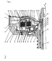
- FIG. 1 shows an embodiment of a dual clutch device 1 with Torsionsschwingungsdämpfer T and inventive dual clutch K1, K2 in radially nested arrangement in Axial direwolf provoke.
- the torsional vibration damper T is basically formed in a conventional manner per se. It comprises a primary element 5 in the manner of a disk and a secondary element 6 with two half-shells 9, 10 in the present embodiment, which are non-rotatable with each other are connected. Primary and secondary elements 5, 6 are coupled together by a spring device and rotated about a neutral position against each other.
- the spring device in the present embodiment consists of a plurality of circumferentially successively arranged coil springs 15, which are spaced apart by means of so-called sliding shoes / spring dividers, not shown here.
- Primary and secondary elements 5, 6 each comprise in a diametrical arrangement two drivers, which engage in each case between the circumferentially extending chain of the coil springs 14, so that a drive side applied to the primary element 5 torque by means of one in the FIG. 1 shown Primärmit interventions 15 is first transmitted to the existing of the coil springs 14 spring chain and from there to the respective Sekundärmit counseling not shown here of the secondary element 6.
- the secondary element 6 comprises two individual parts, namely a drive-side half-shell 9 and a driven-side half-shell 10.
- the two half-shells 9, 10 are designed such that they receive the existing coil springs 14 substantially form-locking. Both half-shells 9, 10 are rotatably connected to each other via a toothing 11. These two half-shells 9, 10 are used for preferably low-friction guidance of the springs 14 and the wiping of the springs 14 arranged in the circumferential direction Gleitschuh / Federetzteiler.
- the double clutch in radially nested arrangement is constructed in a conventional manner. It comprises a radially outer clutch K1 and a radially inner clutch K2.
- the radially outer clutch K1 comprises an outer disk carrier 30 and an inner disk carrier 32. Both disk carriers 30, 32 are designed in the manner of half shells.
- the cylindrical part 55 of the outer disk carrier 30 has a toothing 26 on the inner circumference. In this toothing 26 engages in each case a corresponding external toothing 58 of the present embodiment designed as a steel blades outer plates 36 a.
- the cylindrical part 56 of the inner disk carrier 32 on the outer circumference of a toothing 46, in which a corresponding internal toothing 44 engages here designed as lining plates inner plates 37.
- Outer plate 36 and inner plate 37 are inserted between the cylindrical portions of the outer and inner plate carrier 30, 32 such that an outer plate 36 is followed by an inner plate 37 and vice versa.
- the outer and inner disks 36, 37 are by means of an actuating piston 34 in frictional engagement and frictional engagement.
- the radially inner clutch K2 is executed in the same manner. Again, a half-shell-shaped outer disk carrier 32 and a half-shell-shaped inner disk carrier 31 is provided.
- the half-shell-shaped outer disk carrier 32 is formed by the inner disk carrier 32 supporting the inner disks 37 of the radially outer clutch K1.
- the cylindrical part of this common disk carrier 32 has on the inner peripheral side a toothing 47, in which an external toothing 45 corresponding designed as steel plates External disks 38 engage.
- the cylindrical portion 57 of the inner disk carrier half-shell 31 has an outer toothing 27, which can receive the inner toothings 59 corresponding inner disk 39.
- An inner plate 39 is hereby alternately adjacent to an outer plate 38 a disk set forming arranged. The outer and inner plates 38, 39 can be moved by means of an actuating piston 35 in frictional engagement and frictional engagement.
- the plate packs of the radially outer clutch K1 and the radially inner clutch K2 are arranged to each other in a radially nested manner. This means that the disk set of the radially inner clutch K2 is located radially inside the disk set of the radially outer clutch K1 and in approximately the same axial section as the disk set of the radially outer multi-disk clutch K1.
- the common plate carrier 32 of the radially outer clutch K1 and the radially inner clutch K2 is rotatably connected to a clutch hub 49.
- This clutch hub 49 which has substantially the shape of a cylinder, is mounted rotatably about a rotational axis ax on the outer circumference of a transmission input shaft 21.
- the rotatable mounting via two radial needle bearings 22, 23rd
- the transmission input shaft 21 is in the form of a hollow cylinder. It is centrally penetrated by another designed as a solid shaft transmission input shaft 22. On a with this inner transmission input shaft 20, the solid shaft, rotatably connected hub 28, the primary element 5 of the torsional vibration damper T is rotatably supported by means of a corresponding primary flange 4 about the common axis of rotation ax.
- the storage is realized in the present embodiment by means of a radial needle bearing 25.
- the two transmission input shafts namely the hollow shaft 21 and the solid shaft 20 are rotatably connected in each case with a plate carrier 30, 31 one of the two clutches K1, K2.
- the outer disk carrier 30 of the radially outer multi-disc clutch K1 is rotatably connected to the solid shaft 20 and the inner disk carrier 31 of the radially inner clutch K2 to the hollow shaft 21.
- the plate carriers 30, 31 have corresponding hubs 28, 29, which each have a spline 51, 52 for receiving corresponding toothings of the transmission input shafts 20, 21 at their respective inner circumference.
- the two disk carrier namely the outer disk carrier 30 of the radially outer multi-disc clutch K1 and the inner disc carrier 31 of the radially inner multi-disc clutch K2 are rotatably guided in the hub area by means of a Axialnadellagers 24 against each other.
- the clutch hub 49 and the rotatably connected to this common disc carrier 30 of the radially outer clutch K1 and the radially inner clutch K2 now represent the input side of the dual clutch.
- the outer disc carrier 30 of the radially outer multi-disc clutch K1 and the inner disc carrier 31 of the clutch K2 form the output sides of Double coupling.
- a torque introduced via the clutch hub 49 or the common disk carrier 32 can therefore optionally be transmitted to one of the two disk carriers 31 or 30, depending on the position of the two actuating pistons 34, 35, and from there via the corresponding hubs 28, 29 to the transmission input shafts 20, 21 are discharged.
- the invention now essentially relates to two aspects of the double clutch in radially nested arrangement.
- the first aspect relates to the design of the common plate carrier 32.
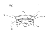
- the common plate carrier 32 comprises a hollow cylindrical section 56 which has toothings 46, 47, corresponding toothings 44 of the inner plates 37 of the radially outer multi-plate clutch K1 as well as toothings 45 the outer disk 38 of the radially inner multi-plate clutch K2 record.
- FIG. 2 shows this hollow cylindrical portion 56 of the common disk carrier 32 in cross section. From the FIG. 2 If one assumes that the common plate carrier 32 has a hollow cylindrical section 56 with a meandering cross section, so that at the same time on the one hand on the outer peripheral side an external toothing 46 for receiving an internal toothing 44 of the inner disk 37 of the radially outer multi-disc clutch K1 and on the other hand inner peripheral side an internal toothing 47 for receiving an external toothing 45 of the outer disk 38 of the radially inner multi-disc clutch K2 is formed.
- This shape of the common disk carrier 32 thus enables the double use (inside and outside) of the disk carrier toothing formed by the meandering shape.
- the second aspect of the invention relates to the axial support plates against which the respective disk packs in the case of actuation of the corresponding couplings K1, K2 are supported, the so-called end plates. While according to the prior art, each clutch K1, K2 has its own end plate for support, according to the invention a common end plate 7 is provided, against which both the disk set of radially inner multi-disc clutch K2 and the disk set of the radially outer multi-disc clutch K1 are supported end.
- the common end plate 7 has for producing a rotationally fixed connection between the common end plate 7 and the common plate carrier 32 a plurality of arranged on an imaginary circle openings 16 through which corresponding in the direction of the axis of rotation ax of the common plate carrier 32 aligned webs 17 are guided.
- the common plate carrier 32 has a circumferential groove 19 for receiving a securing ring 18, by means of which the displaceability of the common end plate 7 in the axial direction ax is limited.
- the inner clutch K2 associated part of the common end plate 7 has a ring tip 43 to a medium force application radius at the radial to the adjacent blade adjust inner multi-plate clutch.
- the radially outer coupling K1 associated portion of the common end plate 7 even has two annular blades 41, 42, so that depending on the force input by the actuating piston 34 either the radially outer annular tip 42 or the radially inner annular tip 41 comes into contact with the adjacent inner disk. In this way, depending on the force input by the actuating piston 34, a different average force application radius.
Claims (9)
- Agencement d'embrayage (1) de construction emboîtée radialement,- avec un embrayage multidisques (K1) radialement extérieur présentant des disques extérieurs (36) et des disques intérieurs (37), et- avec un embrayage multidisques (K2) radialement intérieur présentant des disques extérieurs (38) et des disques intérieurs (39),- l'embrayage multidisques (K1) radialement extérieur et l'embrayage multidisques (K2) radialement intérieur présentant un support de disques commun (32) qui porte les disques extérieurs (38) de l'embrayage multidisques (K2) radialement intérieur et les disques intérieurs (37) de l'embrayage multidisques (K1) radialement extérieur,caractérisé en ce
qu'un plateau d'extrémité commun (7) est prévu pour l'embrayage multirisques (K2) radialement intérieur et l'embrayage multidisques (K1) radialement extérieur - Agencement d'embrayage (1) selon la revendication 1,
caractérisé en ce que
le support de disques commun (32) présente une portion (56) de forme cylindrique creuse avec une section transversale en méandres, de sorte que du côté périphérique extérieur, soit formée une denture extérieure (46) pour recevoir une denture intérieure (44) des disques intérieurs (37) de l'embrayage multidisques (K1) radialement extérieur et que du côté périphérique intérieur, soit formée une denture intérieur (47) pour recevoir une denture extérieure (45) des disques extérieurs (38) de l'embrayage multidisques (K2) radialement intérieur - Agencement d'embrayage (1) selon la revendication 1,
caractérisé en ce que
le support de disques commun (32) est réalisé sous forme de pièce moulée ou emboutie. - Agencement d'embrayage (1) selon l'une quelconque des revendications 1 ou 2,
caractérisé en ce que
le plateau d'extrémité commun (7) est connecté de manière solidaire en rotation au support de disques commun (32) ou en ce que le plateau d'extrémité commun (7) est réalisé d'une seule pièce avec le support de disques commun (32). - Agencement d'embrayage (1) selon la revendication 4,
caractérisé en ce que
le plateau d'extrémité commun (7) présente au moins une ouverture (16), de préférence toutefois plusieurs ouvertures (16) disposés sur un cercle imaginaire, à travers lesquelles sont guidées des nervures (17) correspondantes, orientées de préférence dans la direction d'un axe de rotation (ax) du support de disques commun (32). - Agencement d'embrayage (1) selon l'une quelconque des revendications 4 ou 5,
caractérisé en ce que
le support de disques commun (32) présente une rainure périphérique (19) pour recevoir une bague de fixation (18), à l'aide de laquelle la mobilité du plateau d'extrémité commun (7) dans une direction axiale (ax) est limitée. - Agencement d'embrayage (1) selon l'une quelconque des revendications précédentes,
caractérisé en ce que
le plateau d'extrémité commun (7) présente une première coupe annulaire (41, 43) pour ajuster un rayon d'application de force moyen à un disque, adjacent au plateau d'extrémité commun, de l'embrayage multidisques (K1) radialement extérieur ou de l'embrayage multidisques (K2) radialement intérieur, lorsque la première coupe annulaire (41, 43) est en contact avec le disque adjacent de l'embrayage multidisques correspondant (K1, K2). - Agencement d'embrayage (1) selon la revendication 7,
caractérisé en ce que
le plateau d'extrémité commun (7) présente au moins une autre coupe annulaire (42), afin d'ajuster au moins un autre rayon d'application de force moyenne au disque, adjacent au plateau d'extrémité commun (7), de l'embrayage multidisques (K1) correspondant lorsque l'au moins une autre coupe annulaire (42) est en contact avec le disque adjacent de l'embrayage multidisques correspondant (K1) en plus ou à la place de la première coupe annulaire (41). - Agencement d'embrayage (1) selon l'une quelconque des revendications précédentes,
caractérisé en ce que
le plateau d'extrémité commun (7) est réalisé sous forme de pièce moulée.
Priority Applications (5)
| Application Number | Priority Date | Filing Date | Title |
|---|---|---|---|
| DE502005008046T DE502005008046D1 (de) | 2005-05-25 | 2005-05-25 | Kupplungsanordnung in radial geschachtelter Bauart |
| EP05011339A EP1726842B1 (fr) | 2005-05-25 | 2005-05-25 | Ensemble embrayage avec embrayages voisins dans le sens radial. |
| JP2006117559A JP5063027B2 (ja) | 2005-05-25 | 2006-04-21 | 半径方向に重ねて配置されるクラッチ配置構造 |
| US11/441,308 US7743898B2 (en) | 2005-05-25 | 2006-05-25 | Clutch arrangement having a radially nested design |
| KR1020060047278A KR20060121767A (ko) | 2005-05-25 | 2006-05-25 | 방사상으로 접속된 형태의 클러치 |
Applications Claiming Priority (1)
| Application Number | Priority Date | Filing Date | Title |
|---|---|---|---|
| EP05011339A EP1726842B1 (fr) | 2005-05-25 | 2005-05-25 | Ensemble embrayage avec embrayages voisins dans le sens radial. |
Publications (2)
| Publication Number | Publication Date |
|---|---|
| EP1726842A1 EP1726842A1 (fr) | 2006-11-29 |
| EP1726842B1 true EP1726842B1 (fr) | 2009-09-02 |
Family
ID=35124560
Family Applications (1)
| Application Number | Title | Priority Date | Filing Date |
|---|---|---|---|
| EP05011339A Expired - Fee Related EP1726842B1 (fr) | 2005-05-25 | 2005-05-25 | Ensemble embrayage avec embrayages voisins dans le sens radial. |
Country Status (5)
| Country | Link |
|---|---|
| US (1) | US7743898B2 (fr) |
| EP (1) | EP1726842B1 (fr) |
| JP (1) | JP5063027B2 (fr) |
| KR (1) | KR20060121767A (fr) |
| DE (1) | DE502005008046D1 (fr) |
Cited By (2)
| Publication number | Priority date | Publication date | Assignee | Title |
|---|---|---|---|---|
| DE102013216747A1 (de) | 2013-08-23 | 2015-02-26 | Volkswagen Aktiengesellschaft | Lamellenträger für eine Doppelkupplungsanordnung, Doppelkupplungsanordnung und Verfahren zum Herstellen von Lamellen dafür |
| DE102016215490B3 (de) * | 2016-08-18 | 2018-02-01 | Schaeffler Technologies AG & Co. KG | Doppelkupplung |
Families Citing this family (14)
| Publication number | Priority date | Publication date | Assignee | Title |
|---|---|---|---|---|
| US6965165B2 (en) * | 1998-12-21 | 2005-11-15 | Mou-Shiung Lin | Top layers of metal for high performance IC's |
| DE602006006278D1 (de) * | 2005-12-28 | 2009-05-28 | Honda Motor Co Ltd | Doppelkupplungsvorrichtung |
| DE102006042078B4 (de) * | 2006-09-05 | 2012-04-26 | Ortlinghaus-Werke Gmbh | Kupplung mit einer ersten und einer zweiten Kolben-Zylinder-Einheit |
| DE102007027121B4 (de) * | 2007-06-13 | 2018-02-08 | Volkswagen Ag | Doppelkupplung |
| DE102008008062B4 (de) * | 2008-02-01 | 2014-05-22 | Getrag Getriebe- Und Zahnradfabrik Hermann Hagenmeyer Gmbh & Cie Kg | Doppelkupplungsanordnung |
| WO2010081452A1 (fr) * | 2009-01-19 | 2010-07-22 | Luk Lamellen Und Kupplungsbau Beteiligungs Kg | Ensemble embrayage comprenant un amortisseur de vibrations de torsion |
| DE102010034128A1 (de) * | 2010-08-12 | 2012-02-16 | Borgwarner Inc. | Parallele Doppelkupplungseinrichtung |
| DE102014102515A1 (de) | 2014-02-26 | 2015-08-27 | Getrag Getriebe- Und Zahnradfabrik Hermann Hagenmeyer Gmbh & Cie Kg | Federpaket, Kupplung und Kupplungsherstellungsverfahren |
| EP3034901B1 (fr) | 2014-12-19 | 2020-10-21 | Magna PT B.V. & Co. KG | Système d'embrayage pour une chaîne cinématique de véhicule automobile |
| RU2651367C1 (ru) * | 2017-03-16 | 2018-04-19 | Федеральное государственное унитарное предприятие "Центральный ордена Трудового Красного Знамени научно-исследовательский автомобильный и автомоторный институт "НАМИ" (ФГУП "НАМИ") | Двойное многодисковое сцепление трансмиссии транспортного средства |
| CN110273940B (zh) * | 2018-03-15 | 2022-09-13 | 法雷奥离合器公司 | 具有被构造用于促动盘包的内盘载体的双湿式离合器机构 |
| DE102019104076A1 (de) * | 2019-02-19 | 2020-08-20 | Schaeffler Technologies AG & Co. KG | Kompakte Kupplungsanordnung mit einem Stützkörper |
| EP4001685B1 (fr) * | 2020-11-19 | 2023-10-18 | Mazda Motor Corporation | Véhicule comprenant une transmission automatique |
| KR102594506B1 (ko) * | 2021-12-30 | 2023-10-27 | 주식회사 카펙발레오 | 차량용 토크 컨버터 |
Family Cites Families (28)
| Publication number | Priority date | Publication date | Assignee | Title |
|---|---|---|---|---|
| US872228A (en) * | 1907-07-25 | 1907-11-26 | John J Ghegan | Quadruplex-telegraph system. |
| GB1220351A (en) * | 1967-05-18 | 1971-01-27 | Dunlop Co Ltd | Improvements in disc brakes |
| FR2112653A5 (fr) * | 1970-11-04 | 1972-06-23 | Peugeot & Renault | |
| DE2125850B2 (de) * | 1971-05-25 | 1976-10-21 | ZF Getriebe GmbH, 6600 Saarbrücken | Kupplungsanordnung fuer planetenradgetriebe |
| DE2125861A1 (de) * | 1971-05-25 | 1972-12-07 | Zf Borg Warner Gmbh | Kolben fur durch Druckmittel betätig bare Kupplungen |
| FR2208473A5 (fr) * | 1972-11-24 | 1974-06-21 | Peugeot & Renault | |
| FR2217999A5 (fr) * | 1973-02-13 | 1974-09-06 | Peugeot & Renault | |
| FR2325851A1 (fr) * | 1975-09-25 | 1977-04-22 | Renault | Tambour porte-disques rotatif poour embrayages ou freins multidisques |
| JPS5779332A (en) * | 1980-11-06 | 1982-05-18 | Nissan Motor Co Ltd | Clutch drum |
| US4697477A (en) * | 1984-09-19 | 1987-10-06 | Barr Harold B | Continuously variable transmission |
| JPH0781594B2 (ja) * | 1985-08-31 | 1995-08-30 | 三菱自動車工業株式会社 | 動力伝達装置 |
| JPH05332371A (ja) * | 1992-05-29 | 1993-12-14 | Nissan Motor Co Ltd | 多板クラッチ |
| DE4415664A1 (de) | 1994-05-04 | 1995-11-09 | Zahnradfabrik Friedrichshafen | Kupplungsanordnung |
| US6119817A (en) * | 1997-06-06 | 2000-09-19 | Alliedsignal Inc. | Method of converting an aircraft brake assembly |
| DE10004189C5 (de) | 1999-09-30 | 2015-05-21 | Volkswagen Ag | Mehrfach-Kupplungseinrichtung |
| DE10004186B4 (de) | 1999-09-30 | 2013-03-07 | Volkswagen Ag | Mehrfach-Kupplungseinrichtung |
| EP1195537B1 (fr) | 2000-10-05 | 2003-03-12 | Ford Global Technologies, Inc., A subsidiary of Ford Motor Company | Double embrayage pour une transmission avec deux arbres d'entrée |
| DE10111203A1 (de) | 2000-12-07 | 2002-06-13 | Zf Sachs Ag | Doppel- oder Mehrfach-Lamellen-Kupplungseinrichtung und Lamellenanordnung hierfür |
| EP1585907A3 (fr) | 2001-07-11 | 2005-10-26 | ZF Sachs AG | Systeme d'embrayage multiple a deux configurations d'embrayage accouplables pour entrer en rotation commune |
| DE10203618A1 (de) | 2001-07-31 | 2003-02-13 | Zf Sachs Ag | Mehrfach-Kupplungseinrichtung |
| DE10222933A1 (de) | 2002-05-24 | 2003-12-04 | Zf Sachs Ag | Hydraulisch betätigte Kupplungseinrichtung mit wenigstens einem entlüftbaren bzw. spülbaren hydraulischen Nehmerzylinder und entsprechende hydraulische Nehmerzylinderanordnung |
| DE10223892A1 (de) | 2002-05-29 | 2003-12-11 | Zf Sachs Ag | Mehrfach-Kupplungseinrichtung mit wenigstens zwei Lamellen-Kupplungsanordnungen |
| US6868949B2 (en) * | 2003-02-06 | 2005-03-22 | Borgwarner, Inc. | Start-up clutch assembly |
| DE20310015U1 (de) | 2003-06-18 | 2003-08-28 | Zf Sachs Ag | Kupplungseinrichtung, insbesondere Doppel- oder Mehrfachkupplungseinrichtung, und Dichtungskonzept hierfür |
| DE10333431A1 (de) * | 2003-07-23 | 2005-02-10 | Zf Friedrichshafen Ag | Kupplungsanordnung in einem Automatgetriebe mit bauraumsparender Kühlmittelversorgung |
| US6976568B2 (en) * | 2003-11-18 | 2005-12-20 | Zf Friedrichshafen Ag | Clutch arrangement in a transmission having two axially and radially adjacent clutches |
| US7036645B2 (en) * | 2004-06-18 | 2006-05-02 | General Motors Corporation | Rotating torque-transmitting apparatus |
| DE502004007641D1 (de) * | 2004-06-29 | 2008-08-28 | Borgwarner Inc | Mehrfachkupplungsanordnung |
-
2005
- 2005-05-25 EP EP05011339A patent/EP1726842B1/fr not_active Expired - Fee Related
- 2005-05-25 DE DE502005008046T patent/DE502005008046D1/de active Active
-
2006
- 2006-04-21 JP JP2006117559A patent/JP5063027B2/ja not_active Expired - Fee Related
- 2006-05-25 US US11/441,308 patent/US7743898B2/en active Active
- 2006-05-25 KR KR1020060047278A patent/KR20060121767A/ko not_active Application Discontinuation
Cited By (2)
| Publication number | Priority date | Publication date | Assignee | Title |
|---|---|---|---|---|
| DE102013216747A1 (de) | 2013-08-23 | 2015-02-26 | Volkswagen Aktiengesellschaft | Lamellenträger für eine Doppelkupplungsanordnung, Doppelkupplungsanordnung und Verfahren zum Herstellen von Lamellen dafür |
| DE102016215490B3 (de) * | 2016-08-18 | 2018-02-01 | Schaeffler Technologies AG & Co. KG | Doppelkupplung |
Also Published As
| Publication number | Publication date |
|---|---|
| DE502005008046D1 (de) | 2009-10-15 |
| KR20060121767A (ko) | 2006-11-29 |
| JP5063027B2 (ja) | 2012-10-31 |
| US20060266612A1 (en) | 2006-11-30 |
| EP1726842A1 (fr) | 2006-11-29 |
| US7743898B2 (en) | 2010-06-29 |
| JP2006329421A (ja) | 2006-12-07 |
Similar Documents
| Publication | Publication Date | Title |
|---|---|---|
| EP1726842B1 (fr) | Ensemble embrayage avec embrayages voisins dans le sens radial. | |
| EP1857701B1 (fr) | Disposition d'embrayage multiple | |
| EP1522753B1 (fr) | Embrayage double hydraulique | |
| EP1568906B1 (fr) | Embrayage double | |
| EP1751444B1 (fr) | Systeme d' embrayage, en particulier systeme d'embrayage double, avec un dispositif de positionnement axial du systeme d'embrayage | |
| EP2470808B1 (fr) | Système de double embrayage pour une boîte de vitesses munie de deux arbres d'entrée | |
| EP2153080B1 (fr) | Dispositif d'embrayage double avec element de guidage de piston | |
| EP1339995B1 (fr) | Systeme d'embrayage a double disque ou a disques multiples et dispositif de disques associe | |
| DE102004012948B4 (de) | Doppelkupplungseinrichtung in axialer Bauart | |
| DE102009006647B4 (de) | Doppelkupplungsanordnung | |
| EP2732174B1 (fr) | Double embrayage | |
| DE102009050998B4 (de) | Doppelkupplung für ein automatisches oder automatisiertes Doppelkupplungsgetriebe | |
| DE102008063662A1 (de) | Lamelle für eine reibschlüssig arbeitende Einrichtung und reibschlüssig arbeitende Einrichtung mit einer solchen Lamelle | |
| DE102015213874A1 (de) | Axiale Lamellenkupplung | |
| DE4224361A1 (de) | Planetenradgetriebe-system fuer ein automatisches getriebe | |
| DE102014220897A1 (de) | Kopplungsanordnung mit einer Schwingungsreduzierungseinrichtung und mit einer Kupplungseinrichtung | |
| DE102010034128A1 (de) | Parallele Doppelkupplungseinrichtung | |
| WO2020169140A1 (fr) | Système d'embrayage compact à système support de disques | |
| DE102007027120A1 (de) | Kupplung | |
| DE102006042057B4 (de) | Kupplungsanordnung mit winkelversetzt montierten Lamellen zur Minimierung der Gesamtunwucht | |
| EP1729025B1 (fr) | Dispositif d'embrayage multiple | |
| DE102019126080A1 (de) | Kupplungsanordnung | |
| DE102004007087B4 (de) | Reibungskupplung | |
| DE19881099B3 (de) | Drehschwingungsdämpfer für eine verriegelbare Kupplung, die zu einem hydrodynamischen Momentwandler gehört, insbesondere für Kraftfahrzeuge | |
| EP3622189B1 (fr) | Unité d'embrayage double et propulsion électrique dotée d'une telle unité d'embrayage double |
Legal Events
| Date | Code | Title | Description |
|---|---|---|---|
| PUAI | Public reference made under article 153(3) epc to a published international application that has entered the european phase |
Free format text: ORIGINAL CODE: 0009012 |
|
| AK | Designated contracting states |
Kind code of ref document: A1 Designated state(s): AT BE BG CH CY CZ DE DK EE ES FI FR GB GR HU IE IS IT LI LT LU MC NL PL PT RO SE SI SK TR |
|
| AX | Request for extension of the european patent |
Extension state: AL BA HR LV MK YU |
|
| 17P | Request for examination filed |
Effective date: 20070414 |
|
| AKX | Designation fees paid |
Designated state(s): DE FR GB IT |
|
| 17Q | First examination report despatched |
Effective date: 20080704 |
|
| GRAP | Despatch of communication of intention to grant a patent |
Free format text: ORIGINAL CODE: EPIDOSNIGR1 |
|
| GRAS | Grant fee paid |
Free format text: ORIGINAL CODE: EPIDOSNIGR3 |
|
| GRAA | (expected) grant |
Free format text: ORIGINAL CODE: 0009210 |
|
| AK | Designated contracting states |
Kind code of ref document: B1 Designated state(s): DE FR GB IT |
|
| REF | Corresponds to: |
Ref document number: 502005008046 Country of ref document: DE Date of ref document: 20091015 Kind code of ref document: P |
|
| PLBE | No opposition filed within time limit |
Free format text: ORIGINAL CODE: 0009261 |
|
| STAA | Information on the status of an ep patent application or granted ep patent |
Free format text: STATUS: NO OPPOSITION FILED WITHIN TIME LIMIT |
|
| 26N | No opposition filed |
Effective date: 20100603 |
|
| GBPC | Gb: european patent ceased through non-payment of renewal fee |
Effective date: 20100525 |
|
| PG25 | Lapsed in a contracting state [announced via postgrant information from national office to epo] |
Ref country code: IT Free format text: LAPSE BECAUSE OF FAILURE TO SUBMIT A TRANSLATION OF THE DESCRIPTION OR TO PAY THE FEE WITHIN THE PRESCRIBED TIME-LIMIT Effective date: 20090902 |
|
| PG25 | Lapsed in a contracting state [announced via postgrant information from national office to epo] |
Ref country code: GB Free format text: LAPSE BECAUSE OF NON-PAYMENT OF DUE FEES Effective date: 20100525 |
|
| REG | Reference to a national code |
Ref country code: FR Ref legal event code: PLFP Year of fee payment: 12 |
|
| REG | Reference to a national code |
Ref country code: FR Ref legal event code: PLFP Year of fee payment: 13 |
|
| REG | Reference to a national code |
Ref country code: FR Ref legal event code: PLFP Year of fee payment: 14 |
|
| PGFP | Annual fee paid to national office [announced via postgrant information from national office to epo] |
Ref country code: DE Payment date: 20190412 Year of fee payment: 15 |
|
| PGFP | Annual fee paid to national office [announced via postgrant information from national office to epo] |
Ref country code: FR Payment date: 20190417 Year of fee payment: 15 |
|
| REG | Reference to a national code |
Ref country code: DE Ref legal event code: R119 Ref document number: 502005008046 Country of ref document: DE |
|
| PG25 | Lapsed in a contracting state [announced via postgrant information from national office to epo] |
Ref country code: FR Free format text: LAPSE BECAUSE OF NON-PAYMENT OF DUE FEES Effective date: 20200531 |
|
| PG25 | Lapsed in a contracting state [announced via postgrant information from national office to epo] |
Ref country code: DE Free format text: LAPSE BECAUSE OF NON-PAYMENT OF DUE FEES Effective date: 20201201 |