EP1568906A1 - Embrayage double - Google Patents
Embrayage double Download PDFInfo
- Publication number
- EP1568906A1 EP1568906A1 EP04004484A EP04004484A EP1568906A1 EP 1568906 A1 EP1568906 A1 EP 1568906A1 EP 04004484 A EP04004484 A EP 04004484A EP 04004484 A EP04004484 A EP 04004484A EP 1568906 A1 EP1568906 A1 EP 1568906A1
- Authority
- EP
- European Patent Office
- Prior art keywords
- actuating piston
- double clutch
- clutch according
- disk carrier
- overlaps
- Prior art date
- Legal status (The legal status is an assumption and is not a legal conclusion. Google has not performed a legal analysis and makes no representation as to the accuracy of the status listed.)
- Granted
Links
- 230000005540 biological transmission Effects 0.000 claims abstract description 18
- 230000004323 axial length Effects 0.000 claims abstract description 6
- 230000000295 complement effect Effects 0.000 claims abstract description 3
- 230000008878 coupling Effects 0.000 description 17
- 238000010168 coupling process Methods 0.000 description 17
- 238000005859 coupling reaction Methods 0.000 description 17
- 230000009977 dual effect Effects 0.000 description 12
- 238000005457 optimization Methods 0.000 description 8
- 239000002826 coolant Substances 0.000 description 5
- 229910000831 Steel Inorganic materials 0.000 description 4
- 239000010959 steel Substances 0.000 description 4
- 239000012530 fluid Substances 0.000 description 3
- 239000000969 carrier Substances 0.000 description 2
- 238000001816 cooling Methods 0.000 description 2
- 239000000463 material Substances 0.000 description 2
- 238000003825 pressing Methods 0.000 description 2
- 239000007787 solid Substances 0.000 description 2
- 241000209035 Ilex Species 0.000 description 1
- 238000006243 chemical reaction Methods 0.000 description 1
- 210000000078 claw Anatomy 0.000 description 1
- 238000002485 combustion reaction Methods 0.000 description 1
- 238000010276 construction Methods 0.000 description 1
- 238000011161 development Methods 0.000 description 1
- 230000018109 developmental process Effects 0.000 description 1
- 230000000694 effects Effects 0.000 description 1
- 238000009434 installation Methods 0.000 description 1
- 239000007788 liquid Substances 0.000 description 1
- 238000004519 manufacturing process Methods 0.000 description 1
- 230000013011 mating Effects 0.000 description 1
- 239000002184 metal Substances 0.000 description 1
- 230000004048 modification Effects 0.000 description 1
- 238000012986 modification Methods 0.000 description 1
- 230000003071 parasitic effect Effects 0.000 description 1
- 238000003860 storage Methods 0.000 description 1
Images


Classifications
-
- F—MECHANICAL ENGINEERING; LIGHTING; HEATING; WEAPONS; BLASTING
- F16—ENGINEERING ELEMENTS AND UNITS; GENERAL MEASURES FOR PRODUCING AND MAINTAINING EFFECTIVE FUNCTIONING OF MACHINES OR INSTALLATIONS; THERMAL INSULATION IN GENERAL
- F16D—COUPLINGS FOR TRANSMITTING ROTATION; CLUTCHES; BRAKES
- F16D25/00—Fluid-actuated clutches
- F16D25/06—Fluid-actuated clutches in which the fluid actuates a piston incorporated in, i.e. rotating with the clutch
- F16D25/062—Fluid-actuated clutches in which the fluid actuates a piston incorporated in, i.e. rotating with the clutch the clutch having friction surfaces
- F16D25/063—Fluid-actuated clutches in which the fluid actuates a piston incorporated in, i.e. rotating with the clutch the clutch having friction surfaces with clutch members exclusively moving axially
- F16D25/0635—Fluid-actuated clutches in which the fluid actuates a piston incorporated in, i.e. rotating with the clutch the clutch having friction surfaces with clutch members exclusively moving axially with flat friction surfaces, e.g. discs
- F16D25/0638—Fluid-actuated clutches in which the fluid actuates a piston incorporated in, i.e. rotating with the clutch the clutch having friction surfaces with clutch members exclusively moving axially with flat friction surfaces, e.g. discs with more than two discs, e.g. multiple lamellae
-
- F—MECHANICAL ENGINEERING; LIGHTING; HEATING; WEAPONS; BLASTING
- F16—ENGINEERING ELEMENTS AND UNITS; GENERAL MEASURES FOR PRODUCING AND MAINTAINING EFFECTIVE FUNCTIONING OF MACHINES OR INSTALLATIONS; THERMAL INSULATION IN GENERAL
- F16D—COUPLINGS FOR TRANSMITTING ROTATION; CLUTCHES; BRAKES
- F16D21/00—Systems comprising a plurality of actuated clutches
- F16D21/02—Systems comprising a plurality of actuated clutches for interconnecting three or more shafts or other transmission members in different ways
- F16D21/06—Systems comprising a plurality of actuated clutches for interconnecting three or more shafts or other transmission members in different ways at least two driving shafts or two driven shafts being concentric
-
- F—MECHANICAL ENGINEERING; LIGHTING; HEATING; WEAPONS; BLASTING
- F16—ENGINEERING ELEMENTS AND UNITS; GENERAL MEASURES FOR PRODUCING AND MAINTAINING EFFECTIVE FUNCTIONING OF MACHINES OR INSTALLATIONS; THERMAL INSULATION IN GENERAL
- F16D—COUPLINGS FOR TRANSMITTING ROTATION; CLUTCHES; BRAKES
- F16D25/00—Fluid-actuated clutches
- F16D25/10—Clutch systems with a plurality of fluid-actuated clutches
-
- F—MECHANICAL ENGINEERING; LIGHTING; HEATING; WEAPONS; BLASTING
- F16—ENGINEERING ELEMENTS AND UNITS; GENERAL MEASURES FOR PRODUCING AND MAINTAINING EFFECTIVE FUNCTIONING OF MACHINES OR INSTALLATIONS; THERMAL INSULATION IN GENERAL
- F16D—COUPLINGS FOR TRANSMITTING ROTATION; CLUTCHES; BRAKES
- F16D21/00—Systems comprising a plurality of actuated clutches
- F16D21/02—Systems comprising a plurality of actuated clutches for interconnecting three or more shafts or other transmission members in different ways
- F16D21/06—Systems comprising a plurality of actuated clutches for interconnecting three or more shafts or other transmission members in different ways at least two driving shafts or two driven shafts being concentric
- F16D2021/0661—Hydraulically actuated multiple lamellae clutches
Definitions
- the invention relates to a double clutch according to the preamble of claim 1
- Dual clutches for motor vehicles are differentiated Nature of their friction partners in dry or wet, i. by means of liquid cooling medium cooled, couplings. Furthermore, one can Double clutches differ according to their arrangement. Especially in the wet double clutches, there is the radial into each other nested type ("concentric arrangement") and the axially successively arranged couplings ("parallel arrangement").
- the object of the invention is therefore to provide a double clutch in parallel
- the tension sleeve is the outer disk carrier over its entire axial length overlaps. This makes it possible, the actuating sleeve moving the pulling sleeve to arrange radially within the outer contour of the tension sleeve. The radial space can be small in this way being held.
- the tension sleeve form and functionally complementary to the outer contour of the outer disk carrier, in particular circular cylindrical, is formed. It is merely to ensure that a sufficient axial Hub is possible, which is an actuation of the corresponding Coupling allowed. In this way, the required radial Space on the required for the functionality of the coupling Minimum reduced.
- the tension sleeve (as well as the Outer plate carrier) substantially radially outward leading Has openings. This measure allows an efficient Cooling of rubbing (friction) lamellae by a corresponding over the mutually rubbing surfaces of the Fins guided fluid, e.g. Coolant, efficient radial can be discharged to the outside.
- the invention provides that the tension sleeve the outer disk carrier is mounted axially displaceable.
- a Such storage may be in one or more radial bearings
- the operative connection required to actuate the clutch between the first actuating piston and the tension sleeve can similar to the running between the tension sleeve and Switzerlandhülsendeckel be.
- the first actuating piston at least in a direction of the axis of rotation - namely in the for operating the Coupling force-transmitting direction - only stop limited
- it can also be a two-sided axial fixation be provided.
- the actuating piston and the tension sleeve rotatably or even rigid, e.g. in one piece, to connect with each other.
- the multi-part one-sided stop limited execution has however usually advantages in terms of component complexity (simple pressing parts) and the assembly (easy mating).
- the radial space can be kept small especially by by the first actuating piston axially adjacent to the another of the two clutches is arranged. Do you want the axial Keep space as small as possible, so offers one DE 198 33 376 A1 approximate solution, in which the actuating piston radially inside the disk packs of the two Couplings is arranged. Deviating from this one described there However, the embodiment is preferable, the first one Actuating piston for the first clutch on the axially other Page to arrange. This means in the case where the first clutch is located to the right of the second clutch, that the actuating piston of the first clutch left of Actuating piston of the second clutch is located.
- a wet-running multi-plate clutch is a first compensation space for centrifugal force compensation according to the invention provided for the first actuating piston, which by a driven clutch bell and the first Actuating piston is formed.
- the clutch bell can do this be designed as a clutch bell in the traditional sense, which encloses the entire double clutch like a box. It is also possible that this only as lid-like Flange part is executed, as in an embodiment below will be explained in detail.
- a second compensation space for Centrifugal force compensation for a second to operate the other Clutch hydraulically actuated via a second pressure chamber Actuating piston provided which by a hub cylinder and the second actuating piston is formed.
- the latter two variants provide a defined Pressing force switching the two clutches the double clutch safe even at high speeds.
- a small diameter coupling system is then obtained when the clutch bell cup-like the first actuating piston engages when simultaneously the first actuating piston the outer disc carrier flange pot-like overlaps, if in turn at the same time the outer disk carrier flange the second Actuating piston pot-like overlaps and when finally at the same time the second actuating piston the hub cylinder pot-like overlaps.
- the first actuating piston and / or the second actuating piston a return element, e.g. a diaphragm spring is assigned or are.
- return elements are the respective actuating piston especially in non-hydraulic fluid pressurized Condition spent in defined positions.
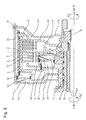
- FIG. 1 illustrates a section of a FIG exemplified powertrain for a motor vehicle a possible basic structure and the operation of an inventive designed double clutch.
- crankshaft On the right side of the drawing figure can over a Spline example, a crankshaft to a clutch bell flange 12 are connected.
- the crankshaft is for example with an internal combustion engine, a Motor or the like coupled.
- This page represents the drive side of the drive train.
- the reverse gear could be both the first transmission input shaft (central or Full shaft 15), as well as the second transmission input shaft Be assigned (hollow shaft 16) of the transmission.
- the dual clutch itself includes two single clutches K1 and K2.
- Each clutch K1, K2 each includes an inner disc carrier 13, 14. Both clutches K1, K2 share a common External disk carrier 6.
- the outer disk carrier of the first clutch K1 is hereinafter referred to as first outer disc carrier 13, the inner disk carrier of the second clutch K2 is referred to below as the second inner disk carrier 14.
- the first inner disk carrier 13 is via a spline with the solid shaft 15 rotatably connected.
- the second inner disk carrier 14 is via a spline with the hollow shaft 16 connected.
- the common outer disk carrier 6 is rotatably with a rotatably mounted about a clutch carrier 10 rotatably mounted clutch hub 5 is connected.
- These Clutch hub 5 is in turn rotatable with one of the two Couplings K1, K2 housing-like clutch bell 8 connected, which in turn by means of a claw toothing rotatably with the aforementioned clutch bell flange 12 and so that it is connected to the drive.
- the two inner disk carrier 13, 14 are half-shell-shaped formed and arranged axially adjacent to each other.
- the outer disc carrier 6 has a substantially cylindrical shape on and extends over the axially extending portions half-shells 13, 14.
- the two inner disk carrier 13, 14 have external teeth on which to the axially displaceable but essentially non-rotatable guidance of three in the present case Internal teeth having friction plates serve.
- the latter are also commonly referred to as inner disks.
- each pressure plate At the two outer ends of the common outer disk carrier 6 are each pressure plates in the same way as the above-mentioned outer plates axially displaceable but in Essentially rotatably guided.
- the two disk packs with the corresponding steel / friction disks are thus on the common outer disk carrier 6 arranged one behind the other in the axial direction.
- the friction surfaces of all Friction blades are essentially the same size, so the individual Couplings K1, K2 have equivalent performance.
- the friction surfaces the friction plates have different diameters.
- Each clutch K1, K2 is a hydraulically actuated actuating piston 4a, 4b assigned.
- Each of these actuating pistons 4a, 4b is for generating the respective clutches K1, K2 provided actuating actuation forces. It means that starting from the respective force-generating actuating piston 4a, 4b corresponding pressure elements against the corresponding the two printing plates are pressed, which are the respective associated disk packs against the common back plate Friction between the adjacent steel / friction plates generating press.
- the main feature of the invention is the outer disk carrier 6 externally encompassing tension sleeve 1, which transmits tensile forces and the "outer" plate set 2a is pressed together for engagement.
- the disk packs 2a, 2b are arranged so that they can use a common back plate 3.
- the axial Actuating forces work against each other and support each other the common back plate from 3.
- the arrangement according to Figure 1 is particularly characterized in that the actuating piston is arranged 4a for the clutch K1 radially outward and thus the forces of the actuating piston 4a are guided very directly, resulting in a total of small deformations of the actuator.
- This piston 4a has a centrifugal force compensation by a Compensation space 7a, which is formed by the clutch bell 8 and the actuating piston 4a itself.
- the second clutch K2 is through the second actuating piston 4b actuated, which in turn has a centrifugal force compensation.
- the required compensation space 7b is formed by the Piston 4b and a hub cylinder 11th
- the dual clutch shown in Figure 1 is driven motor side over the clutch bell flange 12.
- Both clutches K1, K2 have reset elements 17, 18, here for example as disc springs are formed.
- FIG. 2 shows a second embodiment of an inventive Double coupling.
- This double clutch has the essential components identical to the double clutch according to of Figure 1. To facilitate a reference are identical components provided with the same reference numerals.
- the embodiment variant shown in FIG. 2 distinguishes from the according to the figure 1 only by an amended Coolant guide within the coupling device. Especially is an improved in this embodiment Coolant supply of the first clutch K1 ensured.
- FIG. 1 A third variant of a dual clutch according to the invention is shown in FIG. Also this double clutch points the essential components identical to the double clutch according to the figure 1. To facilitate a reference are identical components provided with the same reference numerals.
- the Coupling system has the smallest possible diameter. Since given a system pressure, the pistons 4a, 4b not arbitrary be small, they are staggered here axially one behind the other, wherein the flange 21 of the outer disk carrier 8 between the two pressure chambers 9a, 9b comes to rest. To one To avoid tumbling of the tension sleeve 1, this is at the outer end with a suitable (sliding) bearing element 24 against the outer disk carrier 6 supported.
- FIG. 4 shows a further variant in which the components the hydraulic actuation with regard to a possible short axial length have been optimized. Also this double clutch has the essential components identical to the double clutch according to the figure 1. For a reference To facilitate identical components with the same reference numerals Mistake.
- the pistons 4a, 4b are used to reduce the axial space Nested inside the inner disk carrier 14 nested.
- Figure 5 represents. Also this double clutch has the essential components identical to the Double clutch according to the figure 1 on. For a reference facilitate identical components with the same reference numerals Mistake.
- This variant is a modification of the variant of FIG. 3, the drive is done from the inside out. There are no radially nested hollow shafts within the oil inlet are required, this design can in principle with particular small system diameter to be executed.
Priority Applications (4)
| Application Number | Priority Date | Filing Date | Title |
|---|---|---|---|
| EP04004484A EP1568906B1 (fr) | 2004-02-27 | 2004-02-27 | Embrayage double |
| DE502004007383T DE502004007383D1 (de) | 2004-02-27 | 2004-02-27 | Doppelkupplung |
| JP2004350574A JP2005241000A (ja) | 2004-02-27 | 2004-12-03 | ダブルクラッチ |
| US11/060,645 US7249665B2 (en) | 2004-02-27 | 2005-02-17 | Double clutch |
Applications Claiming Priority (1)
| Application Number | Priority Date | Filing Date | Title |
|---|---|---|---|
| EP04004484A EP1568906B1 (fr) | 2004-02-27 | 2004-02-27 | Embrayage double |
Publications (2)
| Publication Number | Publication Date |
|---|---|
| EP1568906A1 true EP1568906A1 (fr) | 2005-08-31 |
| EP1568906B1 EP1568906B1 (fr) | 2008-06-18 |
Family
ID=34745920
Family Applications (1)
| Application Number | Title | Priority Date | Filing Date |
|---|---|---|---|
| EP04004484A Expired - Lifetime EP1568906B1 (fr) | 2004-02-27 | 2004-02-27 | Embrayage double |
Country Status (4)
| Country | Link |
|---|---|
| US (1) | US7249665B2 (fr) |
| EP (1) | EP1568906B1 (fr) |
| JP (1) | JP2005241000A (fr) |
| DE (1) | DE502004007383D1 (fr) |
Cited By (20)
| Publication number | Priority date | Publication date | Assignee | Title |
|---|---|---|---|---|
| DE102006010113A1 (de) * | 2006-02-28 | 2007-09-20 | Getrag Getriebe- Und Zahnradfabrik Hermann Hagenmeyer Gmbh & Cie Kg | Doppelkupplungsanordnung für ein Doppelkupplungsgetriebe |
| DE102006031788A1 (de) * | 2006-07-10 | 2008-01-17 | Zf Friedrichshafen Ag | Schaltelementanordnung |
| DE102007022419A1 (de) | 2007-05-10 | 2008-11-13 | Borgwarner Inc., Auburn Hills | Doppelwellenkupplungsanordnung mit integrierter Dichtungsfläche |
| DE102007022421A1 (de) | 2007-05-10 | 2008-11-13 | Borgwarner Inc., Auburn Hills | Kupplungssystem für Kraftfahrzeugantriebe |
| DE102007022420A1 (de) | 2007-05-10 | 2008-11-13 | Borgwarner Inc., Auburn Hills | Doppelkupplungsanordnung mit axial kurz bauender Schachtelung von Arbeits- und Ausgleichsraum |
| DE102008055681A1 (de) | 2008-10-28 | 2010-05-06 | Getrag Getriebe- Und Zahnradfabrik Hermann Hagenmeyer Gmbh & Cie Kg | Doppelkupplungsanordnung für ein Doppelkupplungsgetriebe |
| DE102008055682B3 (de) | 2008-10-28 | 2010-06-17 | Getrag Getriebe- Und Zahnradfabrik Hermann Hagenmeyer Gmbh & Cie Kg | Doppelkupplung mit stehendem Kolben und verbesserten Einrücklagern |
| DE102010034128A1 (de) | 2010-08-12 | 2012-02-16 | Borgwarner Inc. | Parallele Doppelkupplungseinrichtung |
| DE102012017955A1 (de) | 2011-11-10 | 2013-05-16 | Borgwarner Inc. | Parallele DoppelkuppIungseinrichtung und Verfahren zum Betrieb einer solchen parallelen Doppelkupplungseinrichtung |
| WO2014044273A3 (fr) * | 2012-09-19 | 2014-07-17 | Schaeffler Technologies AG & Co. KG | Dispositif de débrayage solidaire du plateau de fermeture d'embrayage pour un embrayage double |
| CN106122308A (zh) * | 2016-07-05 | 2016-11-16 | 广州汽车集团股份有限公司 | 一种用于汽车混合动力变速器的离合器装置 |
| EP1764523B2 (fr) † | 2005-09-16 | 2017-10-25 | ZF Friedrichshafen AG | Dispositif d'embrayage à disques multiples |
| WO2017203060A1 (fr) * | 2016-05-27 | 2017-11-30 | Punch Powertrain N.V. | Système d'embrayage et unité d'actionnement associée |
| WO2018041443A1 (fr) * | 2016-09-05 | 2018-03-08 | Volkswagen Aktiengesellschaft | Embrayage multiple pour un véhicule automobile, en particulier pour une propulsion hybride d'un véhicule automobile |
| WO2018050158A1 (fr) * | 2016-09-19 | 2018-03-22 | Schaeffler Technologies AG & Co. KG | Embrayage double pour un véhicule automobile |
| EP1726843B1 (fr) * | 2005-05-25 | 2018-04-04 | BorgWarner, Inc. | Ensemble embrayage |
| DE102007008946B4 (de) | 2006-02-27 | 2018-10-25 | Borgwarner Inc. | Mehrfachkupplung für ein Fahrzeug mit einem Hybridantrieb |
| DE102008016269B4 (de) * | 2008-03-29 | 2019-08-08 | Borgwarner Inc. | Betätigungskolben für eine Reibkupplung und Reibkupplung mit einem solchen Betätigungskolben |
| CN113614405A (zh) * | 2019-03-20 | 2021-11-05 | 舍弗勒技术股份两合公司 | 具有优化的移动摩擦的多片式离合器;混动模块,双离合器装置以及动力总成 |
| DE102012218829B4 (de) | 2011-12-15 | 2021-11-11 | Schaeffler Technologies AG & Co. KG | Doppelkupplung und Verfahren zu deren Montage |
Families Citing this family (21)
| Publication number | Priority date | Publication date | Assignee | Title |
|---|---|---|---|---|
| JP2005164028A (ja) * | 2003-10-06 | 2005-06-23 | Borgwarner Inc | パワートレイン変速機用の混合出力システムを備えたマルチクラッチシステム |
| JP4333469B2 (ja) * | 2004-05-06 | 2009-09-16 | トヨタ自動車株式会社 | 自動変速機のクラッチ装置 |
| US7246692B2 (en) * | 2004-10-26 | 2007-07-24 | Borgwarner Inc. | Dual clutch mechanism for a transmission |
| JP5159613B2 (ja) * | 2005-05-17 | 2013-03-06 | ボーグワーナー インコーポレーテッド | トランスミッション用のデュアルクラッチ機構 |
| JP4714549B2 (ja) * | 2005-10-11 | 2011-06-29 | いすゞ自動車株式会社 | 複式クラッチ装置 |
| DE502005005635D1 (de) * | 2005-10-20 | 2008-11-20 | Getrag Ford Transmissions Gmbh | Doppelkupplung |
| JP5165223B2 (ja) | 2006-09-29 | 2013-03-21 | 本田技研工業株式会社 | 自動二輪車 |
| DE102007024788A1 (de) * | 2007-02-08 | 2008-08-14 | Borgwarner Inc., Auburn Hills | Kupplungseinrichtung mit Befestigungsmittel zur Fixierung der Ausgangsnabe |
| US8967352B2 (en) * | 2007-03-30 | 2015-03-03 | Eaton Corporation | Low driven inertia dual clutch |
| DE102008045791B4 (de) * | 2007-11-11 | 2020-08-06 | Saic Motor Corp. Ltd. | Doppelkupplungsgetriebe und Verfahren zur Montage eines Doppelkupplungsgetriebes |
| DE102008031865A1 (de) * | 2008-02-15 | 2009-08-20 | Borgwarner Inc., Auburn Hills | Kupplungseinrichtung mit einer Welle und einem Nabenteil |
| JP2010133544A (ja) * | 2008-12-08 | 2010-06-17 | Toyota Motor Corp | 自動変速機のピストン装置 |
| GB2476983A (en) * | 2010-01-19 | 2011-07-20 | Gm Global Tech Operations Inc | Double clutch for vehicles |
| US8790211B2 (en) * | 2010-01-26 | 2014-07-29 | GKN Driveline Newton, LLC | Gear assembly for motor vehicle |
| GB2478354A (en) * | 2010-03-05 | 2011-09-07 | Gm Global Tech Operations Inc | Double clutch wear adjuster having a differentiator |
| DE112011105537B4 (de) | 2011-08-18 | 2021-11-04 | Pyong Hwa Valeo Co., Ltd. | Trockene Doppelkupplung |
| DE102011115286A1 (de) * | 2011-09-29 | 2013-04-04 | Borgwarner Inc. | Parallele Doppelkupplungseinrichtung |
| DE102012024699A1 (de) * | 2012-01-13 | 2013-07-18 | Borgwarner Inc. | Kupplungsanordnung mit einer Doppelkupplungseinrichtung |
| EP2762752B1 (fr) * | 2013-01-30 | 2017-06-21 | C.R.F. Società Consortile per Azioni | boîte de vitesses pour véhicule |
| JP6065231B2 (ja) * | 2014-01-28 | 2017-01-25 | マツダ株式会社 | パワートレイン構造 |
| FR3060682B1 (fr) * | 2016-12-21 | 2019-05-17 | Valeo Embrayages | Porte-disques d'entree pour un double embrayage humide, mecanisme et systeme d'embrayage et chaine de transmission hybride integrant un tel porte-disques |
Citations (6)
| Publication number | Priority date | Publication date | Assignee | Title |
|---|---|---|---|---|
| US4966270A (en) * | 1988-06-09 | 1990-10-30 | Dr. Ing. H.C.F. Porsche Aktiengesellschaft | Hydraulically operated double clutch for a motor vehicle |
| US5865289A (en) * | 1996-01-12 | 1999-02-02 | Jatco Corporation | Hydraulic engagement apparatus for automatic transmissions |
| DE19833378A1 (de) * | 1998-07-24 | 1999-12-09 | Getrag Getriebe Zahnrad | Doppelkupplung |
| FR2814516A1 (fr) * | 2000-09-22 | 2002-03-29 | Valeo | Dispositif de transmission a engrenages, en particulier pour vehicule automobile |
| DE10131816A1 (de) * | 2001-06-30 | 2003-01-16 | Zahnradfabrik Friedrichshafen | Schaltelement-Baugruppe für ein Getriebe |
| DE10146606A1 (de) * | 2001-09-21 | 2003-04-10 | Zf Sachs Ag | Mehrfach-Kupplungseinrichtung mit axial nebeneinander angeordneten Lamellen-Kupplungsanordnungen |
Family Cites Families (11)
| Publication number | Priority date | Publication date | Assignee | Title |
|---|---|---|---|---|
| DE1160308B (de) * | 1957-02-23 | 1963-12-27 | Daimler Benz Ag | Planetenraederwechselgetriebe, insbesondere fuer Kraftfahrzeuge |
| GB956219A (en) * | 1961-12-02 | 1964-04-22 | Daimler Benz Ag | Improvements in friction clutch arrangements comprising power means for the operation thereof |
| US4237749A (en) * | 1979-05-11 | 1980-12-09 | General Motors Corporation | Multi-speed power transmission |
| JPH0794856B2 (ja) * | 1985-12-16 | 1995-10-11 | アイシン・エィ・ダブリュ株式会社 | 自動変速機におけるクラツチ装置 |
| JP3193030B2 (ja) * | 1987-12-19 | 2001-07-30 | ルーク・ラメレン・ウント・クップルングスバウ・ゲゼルシヤフト・ミツト・ベシユレンクテル・ハフツング | クラッチユニット |
| JP3354303B2 (ja) * | 1994-08-19 | 2002-12-09 | 本田技研工業株式会社 | タンデム型油圧クラッチ |
| JPH1151081A (ja) * | 1997-08-04 | 1999-02-23 | Toyota Motor Corp | ピストン機構 |
| DE10004186B4 (de) * | 1999-09-30 | 2013-03-07 | Volkswagen Ag | Mehrfach-Kupplungseinrichtung |
| EP1195537B1 (fr) * | 2000-10-05 | 2003-03-12 | Ford Global Technologies, Inc., A subsidiary of Ford Motor Company | Double embrayage pour une transmission avec deux arbres d'entrée |
| JP3614390B2 (ja) * | 2001-09-28 | 2005-01-26 | アイシン・エィ・ダブリュ株式会社 | 自動変速機のクラッチ装置 |
| JP3513135B2 (ja) * | 2001-11-26 | 2004-03-31 | 富士重工業株式会社 | 車両用変速装置 |
-
2004
- 2004-02-27 DE DE502004007383T patent/DE502004007383D1/de not_active Expired - Lifetime
- 2004-02-27 EP EP04004484A patent/EP1568906B1/fr not_active Expired - Lifetime
- 2004-12-03 JP JP2004350574A patent/JP2005241000A/ja active Pending
-
2005
- 2005-02-17 US US11/060,645 patent/US7249665B2/en active Active
Patent Citations (6)
| Publication number | Priority date | Publication date | Assignee | Title |
|---|---|---|---|---|
| US4966270A (en) * | 1988-06-09 | 1990-10-30 | Dr. Ing. H.C.F. Porsche Aktiengesellschaft | Hydraulically operated double clutch for a motor vehicle |
| US5865289A (en) * | 1996-01-12 | 1999-02-02 | Jatco Corporation | Hydraulic engagement apparatus for automatic transmissions |
| DE19833378A1 (de) * | 1998-07-24 | 1999-12-09 | Getrag Getriebe Zahnrad | Doppelkupplung |
| FR2814516A1 (fr) * | 2000-09-22 | 2002-03-29 | Valeo | Dispositif de transmission a engrenages, en particulier pour vehicule automobile |
| DE10131816A1 (de) * | 2001-06-30 | 2003-01-16 | Zahnradfabrik Friedrichshafen | Schaltelement-Baugruppe für ein Getriebe |
| DE10146606A1 (de) * | 2001-09-21 | 2003-04-10 | Zf Sachs Ag | Mehrfach-Kupplungseinrichtung mit axial nebeneinander angeordneten Lamellen-Kupplungsanordnungen |
Cited By (41)
| Publication number | Priority date | Publication date | Assignee | Title |
|---|---|---|---|---|
| EP1726843B1 (fr) * | 2005-05-25 | 2018-04-04 | BorgWarner, Inc. | Ensemble embrayage |
| EP1764523B2 (fr) † | 2005-09-16 | 2017-10-25 | ZF Friedrichshafen AG | Dispositif d'embrayage à disques multiples |
| DE102007008946B4 (de) | 2006-02-27 | 2018-10-25 | Borgwarner Inc. | Mehrfachkupplung für ein Fahrzeug mit einem Hybridantrieb |
| DE102007008946C5 (de) | 2006-02-27 | 2021-10-07 | Borgwarner Inc. | Mehrfachkupplung für ein Fahrzeug mit einem Hybridantrieb |
| DE102006010113C5 (de) * | 2006-02-28 | 2010-05-20 | Getrag Getriebe- Und Zahnradfabrik Hermann Hagenmeyer Gmbh & Cie Kg | Doppelkupplungsanordnung für ein Doppelkupplungsgetriebe |
| DE102006010113B4 (de) * | 2006-02-28 | 2007-11-29 | Getrag Getriebe- Und Zahnradfabrik Hermann Hagenmeyer Gmbh & Cie Kg | Doppelkupplungsanordnung für ein Doppelkupplungsgetriebe |
| DE102006010113A1 (de) * | 2006-02-28 | 2007-09-20 | Getrag Getriebe- Und Zahnradfabrik Hermann Hagenmeyer Gmbh & Cie Kg | Doppelkupplungsanordnung für ein Doppelkupplungsgetriebe |
| US7712594B2 (en) | 2006-02-28 | 2010-05-11 | Getrag Getriebe- Und Zahnradfabrik Hermann Hagenmeyer Gmbh & Cie Kg | Dual clutch arrangement for a dual clutch transmission |
| DE102006031788A1 (de) * | 2006-07-10 | 2008-01-17 | Zf Friedrichshafen Ag | Schaltelementanordnung |
| DE102007022419A1 (de) | 2007-05-10 | 2008-11-13 | Borgwarner Inc., Auburn Hills | Doppelwellenkupplungsanordnung mit integrierter Dichtungsfläche |
| WO2008138506A1 (fr) * | 2007-05-10 | 2008-11-20 | Borgwarner Inc. | Dispositif double-embrayage à chevauchement axial court de la chambre de travail et de la chambre de compensation |
| DE102007022421B4 (de) * | 2007-05-10 | 2020-03-05 | Borgwarner Inc. | Kupplungssystem für Kraftfahrzeugantriebe |
| DE102007022420A1 (de) | 2007-05-10 | 2008-11-13 | Borgwarner Inc., Auburn Hills | Doppelkupplungsanordnung mit axial kurz bauender Schachtelung von Arbeits- und Ausgleichsraum |
| DE102007022421A1 (de) | 2007-05-10 | 2008-11-13 | Borgwarner Inc., Auburn Hills | Kupplungssystem für Kraftfahrzeugantriebe |
| DE102008016269B4 (de) * | 2008-03-29 | 2019-08-08 | Borgwarner Inc. | Betätigungskolben für eine Reibkupplung und Reibkupplung mit einem solchen Betätigungskolben |
| DE102008055682B3 (de) | 2008-10-28 | 2010-06-17 | Getrag Getriebe- Und Zahnradfabrik Hermann Hagenmeyer Gmbh & Cie Kg | Doppelkupplung mit stehendem Kolben und verbesserten Einrücklagern |
| EP2532912A1 (fr) | 2008-10-28 | 2012-12-12 | GETRAG Getriebe- und Zahnradfabrik Hermann Hagenmeyer GmbH & Cie KG | Dispositif à double embrayage pour un engrenage à double embrayage |
| EP3139053A1 (fr) | 2008-10-28 | 2017-03-08 | GETRAG Getriebe- und Zahnradfabrik Hermann Hagenmeyer GmbH & Cie KG | Double embrayage dote d'un piston vertical et de butees d'embrayage ameliorees |
| EP2703675A1 (fr) | 2008-10-28 | 2014-03-05 | GETRAG Getriebe- und Zahnradfabrik Hermann Hagenmeyer GmbH & Cie KG | Double embrayage doté d'un piston vertical et de butées d'embrayage améliorées |
| DE102008055682C5 (de) * | 2008-10-28 | 2017-11-02 | Getrag Getriebe- Und Zahnradfabrik Hermann Hagenmeyer Gmbh & Cie Kg | Doppelkupplung mit stehendem Kolben und verbesserten Einrücklagern |
| DE102008055681A1 (de) | 2008-10-28 | 2010-05-06 | Getrag Getriebe- Und Zahnradfabrik Hermann Hagenmeyer Gmbh & Cie Kg | Doppelkupplungsanordnung für ein Doppelkupplungsgetriebe |
| DE102008055681B4 (de) * | 2008-10-28 | 2020-10-15 | Magna Pt B.V. & Co. Kg | Doppelkupplungsanordnung für ein Doppelkupplungsgetriebe |
| US8991577B2 (en) | 2010-08-12 | 2015-03-31 | Borgwarner Inc. | Parallel dual clutch unit |
| DE102010034128A1 (de) | 2010-08-12 | 2012-02-16 | Borgwarner Inc. | Parallele Doppelkupplungseinrichtung |
| WO2012021363A2 (fr) | 2010-08-12 | 2012-02-16 | Borgwarner Inc. | Unité de double embrayage parallèle |
| DE102012017955A1 (de) | 2011-11-10 | 2013-05-16 | Borgwarner Inc. | Parallele DoppelkuppIungseinrichtung und Verfahren zum Betrieb einer solchen parallelen Doppelkupplungseinrichtung |
| DE102012218829B4 (de) | 2011-12-15 | 2021-11-11 | Schaeffler Technologies AG & Co. KG | Doppelkupplung und Verfahren zu deren Montage |
| WO2014044273A3 (fr) * | 2012-09-19 | 2014-07-17 | Schaeffler Technologies AG & Co. KG | Dispositif de débrayage solidaire du plateau de fermeture d'embrayage pour un embrayage double |
| WO2017203060A1 (fr) * | 2016-05-27 | 2017-11-30 | Punch Powertrain N.V. | Système d'embrayage et unité d'actionnement associée |
| CN109790881A (zh) * | 2016-05-27 | 2019-05-21 | 邦奇动力有限责任公司 | 离合器系统以及用于该离合器系统的致动单元 |
| US10823280B2 (en) | 2016-05-27 | 2020-11-03 | Punch Powertrain N.V. | Clutch system and actuation unit therefore |
| BE1024240B1 (nl) * | 2016-05-27 | 2018-01-10 | Punch Powertrain Nv | Koppelingssysteem en actuatie daarvoor |
| CN106122308B (zh) * | 2016-07-05 | 2018-10-19 | 广州汽车集团股份有限公司 | 一种用于汽车混合动力变速器的离合器装置 |
| CN106122308A (zh) * | 2016-07-05 | 2016-11-16 | 广州汽车集团股份有限公司 | 一种用于汽车混合动力变速器的离合器装置 |
| CN109642622A (zh) * | 2016-09-05 | 2019-04-16 | 大众汽车有限公司 | 用于机动车、尤其用于机动车的混合驱动装置的多重离合器 |
| CN109642622B (zh) * | 2016-09-05 | 2020-08-25 | 大众汽车有限公司 | 用于机动车、尤其用于机动车的混合驱动装置的多重离合器 |
| WO2018041443A1 (fr) * | 2016-09-05 | 2018-03-08 | Volkswagen Aktiengesellschaft | Embrayage multiple pour un véhicule automobile, en particulier pour une propulsion hybride d'un véhicule automobile |
| CN109661524A (zh) * | 2016-09-19 | 2019-04-19 | 舍弗勒技术股份两合公司 | 用于机动车的双离合器 |
| WO2018050158A1 (fr) * | 2016-09-19 | 2018-03-22 | Schaeffler Technologies AG & Co. KG | Embrayage double pour un véhicule automobile |
| CN109661524B (zh) * | 2016-09-19 | 2021-04-20 | 舍弗勒技术股份两合公司 | 用于机动车的双离合器 |
| CN113614405A (zh) * | 2019-03-20 | 2021-11-05 | 舍弗勒技术股份两合公司 | 具有优化的移动摩擦的多片式离合器;混动模块,双离合器装置以及动力总成 |
Also Published As
| Publication number | Publication date |
|---|---|
| DE502004007383D1 (de) | 2008-07-31 |
| EP1568906B1 (fr) | 2008-06-18 |
| JP2005241000A (ja) | 2005-09-08 |
| US7249665B2 (en) | 2007-07-31 |
| US20050189195A1 (en) | 2005-09-01 |
Similar Documents
| Publication | Publication Date | Title |
|---|---|---|
| EP1568906B1 (fr) | Embrayage double | |
| EP1522753B1 (fr) | Embrayage double hydraulique | |
| DE102007008946C5 (de) | Mehrfachkupplung für ein Fahrzeug mit einem Hybridantrieb | |
| EP3139053B1 (fr) | Double embrayage dote d'un piston vertical et de butees d'embrayage ameliorees | |
| EP3135522B1 (fr) | Module hybride et procédé permettant la transmission d'un couple dans une chaîne cinématique d'un véhicule automobile | |
| EP2153080B1 (fr) | Dispositif d'embrayage double avec element de guidage de piston | |
| EP1726842B1 (fr) | Ensemble embrayage avec embrayages voisins dans le sens radial. | |
| DE102007003107A1 (de) | Dreifachkupplung für Hybridantrieb mit Doppelkupplungsgetriebe | |
| DE102015215895A1 (de) | Kupplungseinrichtung für Hybridantrieb | |
| DE102013216333A1 (de) | Mehrfachkupplungsvorrichtung, insbesondere Doppelkupplungsvorrichtung | |
| DE102011009419A1 (de) | Mehrfachkupplungseinrichtung und Antriebsstrang mit einer solchen Mehrfachkupplungseinrichtung | |
| DE102007050235A1 (de) | Antriebssystem für ein Fahrzeug | |
| DE102015205574A1 (de) | Doppelkupplung | |
| DE102011013479A1 (de) | Doppelkupplung | |
| DE102019122813B4 (de) | Axialkraftaktor | |
| DE112011100684T5 (de) | Scheibenelement und mit Scheibenelement versehene Bremsvorrichtung | |
| WO2008131815A1 (fr) | Ensemble embrayage double muni d'un système de débrayage électromécanique | |
| DE102006042057A1 (de) | Kupplungsanordnung | |
| DE102014212800A1 (de) | Antriebsstrang für ein Kraftfahrzeug | |
| DE102009016282B4 (de) | Zweifach wirkende Kupplungsvorrichtung für kompaktes elektromechanisches Getriebe | |
| DE102021126008A1 (de) | Lamellenkupplung mit Sicherungselement zur Sicherung des Stütztrings eines Lamellenpakets | |
| EP1686275B1 (fr) | Embrayage double | |
| DE10016602B4 (de) | Doppelkupplungsanordnung | |
| WO2022028642A1 (fr) | Embrayage de séparation actionné par milieu sous pression qui est normalement fermé, comprenant un dispositif d'actionnement qui tourne avec celui-ci et qui chevauche axialement un dispositif amortisseur | |
| DE102021128107A1 (de) | Nasskupplung mit Kühlölführung |
Legal Events
| Date | Code | Title | Description |
|---|---|---|---|
| PUAI | Public reference made under article 153(3) epc to a published international application that has entered the european phase |
Free format text: ORIGINAL CODE: 0009012 |
|
| AK | Designated contracting states |
Kind code of ref document: A1 Designated state(s): AT BE BG CH CY CZ DE DK EE ES FI FR GB GR HU IE IT LI LU MC NL PT RO SE SI SK TR |
|
| AX | Request for extension of the european patent |
Extension state: AL LT LV MK |
|
| RAP1 | Party data changed (applicant data changed or rights of an application transferred) |
Owner name: BORGWARNER INC. |
|
| 17P | Request for examination filed |
Effective date: 20050924 |
|
| AKX | Designation fees paid |
Designated state(s): DE FR GB IT |
|
| GRAP | Despatch of communication of intention to grant a patent |
Free format text: ORIGINAL CODE: EPIDOSNIGR1 |
|
| GRAS | Grant fee paid |
Free format text: ORIGINAL CODE: EPIDOSNIGR3 |
|
| GRAA | (expected) grant |
Free format text: ORIGINAL CODE: 0009210 |
|
| AK | Designated contracting states |
Kind code of ref document: B1 Designated state(s): DE FR GB IT |
|
| REG | Reference to a national code |
Ref country code: GB Ref legal event code: FG4D Free format text: NOT ENGLISH |
|
| REF | Corresponds to: |
Ref document number: 502004007383 Country of ref document: DE Date of ref document: 20080731 Kind code of ref document: P |
|
| PLBE | No opposition filed within time limit |
Free format text: ORIGINAL CODE: 0009261 |
|
| STAA | Information on the status of an ep patent application or granted ep patent |
Free format text: STATUS: NO OPPOSITION FILED WITHIN TIME LIMIT |
|
| 26N | No opposition filed |
Effective date: 20090319 |
|
| GBPC | Gb: european patent ceased through non-payment of renewal fee |
Effective date: 20090227 |
|
| PG25 | Lapsed in a contracting state [announced via postgrant information from national office to epo] |
Ref country code: GB Free format text: LAPSE BECAUSE OF NON-PAYMENT OF DUE FEES Effective date: 20090227 |
|
| REG | Reference to a national code |
Ref country code: FR Ref legal event code: PLFP Year of fee payment: 12 |
|
| PGFP | Annual fee paid to national office [announced via postgrant information from national office to epo] |
Ref country code: IT Payment date: 20150219 Year of fee payment: 12 |
|
| PGFP | Annual fee paid to national office [announced via postgrant information from national office to epo] |
Ref country code: FR Payment date: 20150126 Year of fee payment: 12 |
|
| REG | Reference to a national code |
Ref country code: FR Ref legal event code: ST Effective date: 20161028 |
|
| PG25 | Lapsed in a contracting state [announced via postgrant information from national office to epo] |
Ref country code: IT Free format text: LAPSE BECAUSE OF NON-PAYMENT OF DUE FEES Effective date: 20160227 |
|
| PG25 | Lapsed in a contracting state [announced via postgrant information from national office to epo] |
Ref country code: FR Free format text: LAPSE BECAUSE OF NON-PAYMENT OF DUE FEES Effective date: 20160229 |
|
| PGFP | Annual fee paid to national office [announced via postgrant information from national office to epo] |
Ref country code: DE Payment date: 20230111 Year of fee payment: 20 |
|
| P01 | Opt-out of the competence of the unified patent court (upc) registered |
Effective date: 20230327 |
|
| REG | Reference to a national code |
Ref country code: DE Ref legal event code: R071 Ref document number: 502004007383 Country of ref document: DE |