EP1552805B1 - Vorrichtung zur abgabe von medikamenten - Google Patents
Vorrichtung zur abgabe von medikamenten Download PDFInfo
- Publication number
- EP1552805B1 EP1552805B1 EP03733317.6A EP03733317A EP1552805B1 EP 1552805 B1 EP1552805 B1 EP 1552805B1 EP 03733317 A EP03733317 A EP 03733317A EP 1552805 B1 EP1552805 B1 EP 1552805B1
- Authority
- EP
- European Patent Office
- Prior art keywords
- cassette
- dispensing
- stopping
- medicines
- medicine
- Prior art date
- Legal status (The legal status is an assumption and is not a legal conclusion. Google has not performed a legal analysis and makes no representation as to the accuracy of the status listed.)
- Expired - Lifetime
Links
Images


Classifications
-
- A—HUMAN NECESSITIES
- A61—MEDICAL OR VETERINARY SCIENCE; HYGIENE
- A61J—CONTAINERS SPECIALLY ADAPTED FOR MEDICAL OR PHARMACEUTICAL PURPOSES; DEVICES OR METHODS SPECIALLY ADAPTED FOR BRINGING PHARMACEUTICAL PRODUCTS INTO PARTICULAR PHYSICAL OR ADMINISTERING FORMS; DEVICES FOR ADMINISTERING FOOD OR MEDICINES ORALLY; BABY COMFORTERS; DEVICES FOR RECEIVING SPITTLE
- A61J3/00—Devices or methods specially adapted for bringing pharmaceutical products into particular physical or administering forms
-
- G—PHYSICS
- G07—CHECKING-DEVICES
- G07F—COIN-FREED OR LIKE APPARATUS
- G07F11/00—Coin-freed apparatus for dispensing, or the like, discrete articles
- G07F11/02—Coin-freed apparatus for dispensing, or the like, discrete articles from non-movable magazines
- G07F11/38—Coin-freed apparatus for dispensing, or the like, discrete articles from non-movable magazines in which the magazines are horizontal
-
- G—PHYSICS
- G07—CHECKING-DEVICES
- G07F—COIN-FREED OR LIKE APPARATUS
- G07F11/00—Coin-freed apparatus for dispensing, or the like, discrete articles
- G07F11/02—Coin-freed apparatus for dispensing, or the like, discrete articles from non-movable magazines
- G07F11/04—Coin-freed apparatus for dispensing, or the like, discrete articles from non-movable magazines in which magazines the articles are stored one vertically above the other
- G07F11/16—Delivery means
- G07F11/165—Delivery means using xyz-picker or multi-dimensional article picking arrangements
-
- G—PHYSICS
- G07—CHECKING-DEVICES
- G07F—COIN-FREED OR LIKE APPARATUS
- G07F17/00—Coin-freed apparatus for hiring articles; Coin-freed facilities or services
- G07F17/0092—Coin-freed apparatus for hiring articles; Coin-freed facilities or services for assembling and dispensing of pharmaceutical articles
Definitions
- the present invention relates to a device for dispensing medicine capable of dispensing medicines one by one.
- the medicine should be grasped from an upper aperture of the pulled-out cassette, and therefore the contained medicine is sometimes difficult to extract depending on the arranged position of the cassette.
- the number of medicines contained in the cassette increases, not only the cassette itself is difficult to pull out but also the medicines contained on the inner side of the cassette are hard to extract.
- a medicine such as anticancer drugs whose administration is strictly restricted, it is not desirable to allow free access to the medicine.
- adopting the structure featuring such solution as locking will deteriorate workability and also require an additional operation to confirm that the medicines are securely locked up.
- EP 1 118 318 A2 discloses a medicine storage apparatus including a cassette having an inlet-outlet opening for delivering/receiving items of medicine therethrough and adapted to store items of medicine arranged in array while a force is applied to the items of medicine toward the inlet-outlet opening.
- a support mechanism is provided for supporting the cassette while the inlet-outlet opening is exposed.
- a counting mechanism is provided for counting the number of items of medicines stored in the cassette.
- JP 2000 072204 A discloses an automatic delivery apparatus for injections, comprising a transfer means for taking out the injections in the ampoules stored in an injection feed cassette and delivering them to a prescribed position, wherein the injection feed cassette involves a table part in which a plurality of injections in ampoules are arranged.
- WO 01/72612 A1 discloses an injection drug feeding device, wherein an injection drug storage container is installed detachably on each of a plurality of racks.
- a transfer means feeding the stored injection drugs in one direction is installed in the injection drug storage container.
- the injection drugs fed by the transfer means are stored one by one in each storage part formed in the outer peripheral part of a rotating body and the injection drugs in the storage parts are delivered one by one in order by the rotation of the rotating body.
- JP-A-2000-024085 discloses a medicine dispenser having a number of medicine cassettes to store medicines for preparation.
- JP-A-2002-011072 discloses a drug storage device comprising multiple cassettes for aligning and stocking drugs.
- US 6,138,865 discloses an automatic medicament dispenser system and a mobile medicine storage unit for individuals under a doctor's care.
- the unit is programmable and preferably fully automatic, but also manual in dispensing any number of medications up to four times a day at preselected times.
- An object of the present invention is to provide a device for dispensing medicine in which cassettes are downsized so as to be arranged at a high density and a desired number of medicines can be dispensed surely.
- a device for dispensing medicine including a dispensing device body, a cassette fixed removably to the dispensing device body in order to contain medicines while arranging, and pushing means for pushing out the medicines in the cassette toward one end side
- the cassette including a cover to arrange the contained medicines and a stopping/receiving part disposed internally in a longitudinal direction
- the pushing means including an abutting part contained in the cassette and abutting against the medicines, a biasing part for biasing the abutting part against the medicine so as to press and arrange the medicines from one end side, and a stopping part stopping at the stopping/receiving part of the cassette only when the cover is opened so that the abutting part is prevented from pressing the medicines in conformity to biasing force of the biasing part, wherein when the abutting part is moved, the stopping part is released from the stopping/receiving part and the abutting part is moved to an arbitrary position so as to allow positioning.
- This constitution allows compact structure of the cassette so that the cassette can be arranged at a high density in the dispensing device body. Moreover, the operation of the biasing part eliminates the necessity of a specific driving source, allowing easy extraction of medicines. Further, in the pushing means, the stopping part is stopped at the stopping/receiving part in the state that the cover is open, thereby preventing failures such as fallout of the medicines during supplementing operation of medicines.
- the pushing means is constituted such that the biasing part and the stopping part are housed in a casing and one end face of the casing functions as the abutting part, which allows simple and compact formation of the pushing means.
- the cassette includes fallout preventing means for preventing contained medicines from falling out in the state that the cassette is dismounted from the dispensing device body, the dispensing device body including a canceling part for canceling fallout prevention by the fallout preventing means when the cassette is mounted on or dismounted from the dispensing device body and a dispensing part for allowing the medicines in the cassette to be dispensed one by one, which ensures prevention of the medicines from falling out when the cassette is mounted on or dismounted from the dispensing device body and allows the medicines to be dispensed surely one by one.
- the stopping/receiving part is constituted of a stopping rack composed of a plurality of recess parts juxtaposed along the longitudinal direction of the cassette, and the stopping part has a gear which turns in response to opening and closing operation of the cover to engage with the stopping rack, which makes it possible to ensure positioning of the pushing means when the cover is opened with the constitution.
- the pushing means includes a gear engaged with the stopping rack and an oil dumper integrated with the gear, and the biasing part is constituted of a constant-load spring, which enables the pushing means to smoothly and reasonably push out medicines.
- the dispensing part should be constituted of a rotor having a circular plane allowing medicines to be held one by one, the rotor being rotated by power transmitted through a gear provided on a rotating shaft, the gear being engaged with a rack formed on a rod, the rod being able to reciprocate.
- the dispensing part is constituted of a rotor having a circular plane allowing medicines to be held one by one, the rotor being rotated by power transmitted through a gear provided on a rotating shaft, the gear being engaged with a drive gear which drives rotationally, the drive gear being able to come into contact with or break away from the gear of each rotor in a plurality of cassettes, which enables a single-unit drive gear to dispense medicines from a plurality of cassettes.
- the fallout prevention means is constituted of a plate spring provided on one end aperture of the cassette, the plate spring being elastically deformable from being at a fallout prevention position for preventing medicines from falling out from the cassettes to being at a medicine dispensing position for permitting the dispensing part to dispense medicines.
- the plate spring elastically supports a head medicine so as not to move the position of the next medicine when the head medicine received on the circular plane of the rotor is dispensed from the cassette by rotation of rotor, which allows smooth rotating operation of the rotor.
- the dispensing device body includes a pusher for driving the dispensing part of the cassette to dispense medicines and a stopping/retaining member geared to the pusher to engage with or disengage from the cassette, which makes it possible to prevent failures such as careless dismounting of the cassette during dispensing of medicines.
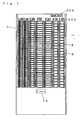
- Fig. 1 and Fig. 2 show a device for dispensing medicine according to the present embodiment.
- the device for dispensing medicine is structured such that cassettes 2 are mounted on a dispensing device body 1 in matrix form. Medicines D in each of the cassettes 2 are dispensed by a dispensing unit 30 to a dispensing outlet 1a on the lower front side of the dispensing device body 1.
- the dispensing device body 1 has a plurality of stock shelves 3 on which the cassettes 2 are mounted. On the inner side of each of the stock shelves 3, a cancel part and a dispensing part are formed.
- the cancel part is constituted of a protrusion 4 which abuts against a later-described stopper cancel member 13.
- the dispensing part is constituted of a rotor 5 which rotates by the operation of a later-deseribed rotor drive member 31 through a gear 5a provided on one end portion of a rotating shaft.
- the rotor 5 receives a medicine D (herein an ampul) from the cassette 2 on a circular plane 5b formed by cutting away, and rotates so as to support the next medicine D on an outer circumferential plane 5c, so that only the medicine D received on the circular plane 5b is discharged.
- the center of rotation O of the rotor 5 is positioned above a center line C of a discharge route of medicines.
- the circular plane 5b is in the shape which allows dispensing of only one medicine D even if the medicine D has a maximum outer diameter and which prevents interference with the next medicine D. This allows the rotors 5 of the same shape to be used to handle a plurality of medicines D different in outer diameter size.
- reference numeral 1b denotes guide pieces for guiding the rear end portion of the cassette 2.
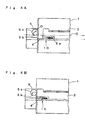
- the cassette 2 is in a vertically-long box shape and its upper face is closed by a cover 6 provided movably around a spindle 6a.
- the cover 6 has a pressing part 7 formed so as to extend in the longitudinal direction in its center portion, the pressing part 7 being able to abut against the contained medicines D so as to offer a desired array state.
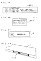
- One end face of the cassette 2 (positioned on the front face side of the dispensing device body 1) serves as a display part 8 carrying cassette No., name of contained medicine D and capacity as shown in Fig. 17 , and in the vicinity of the display part 8, a stopping part 9 for maintaining the cassette 2 in the state of being closed with respect to the stock shelf 3 is formed.
- the display part 8 may carry the external picture of the contained medicine D (ampule), a barcode to identify the medicine D and the like in addition to the cassette No. and other information.
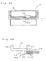
- a stopper 10 is provided as a fallout prevention means.
- the stopper 10 is disposed in a recess part 2a formed on the lower face of the cassette 2 and is supported rotatably around a shaft part 10a protruding from both sides as shown in Fig. 4D .
- a rectangular part 11 is formed around the shaft part 10a and its end curves at almost right angles to serve as a fallout prevention part 12.
- the stopper 10 is positioned at a closing position at which the stopper cancel member 13 prevents the medicine D from falling out of the cassette 2 and at an opening position at which fallout is allowed.
- the stopper cancel member 13 is biased by a spring 14 so as to protrude in the horizontal direction.
- a guide part 15 and a relief part 16 are formed on the stopper cancel member 13, a guide part 15 and a relief part 16 are formed.
- the guide part 15 is formed to have a laterally-positioned U shape cross section so as to be able to guide the bottom face and the lower side face of the rectangular part 11 in the stopper 10.
- the relief part 16 is constituted of only wall faces of both sides so that the stopper 10 can be rotated by pressing the stopper cancel member 13 against the biasing force of the spring 14.
- reference numeral 13a denotes a contact piece, which is pressed by a protrusion 4 of the dispensing device body 1.
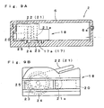
- a stopping rack 17 is formed in the longitudinal direction as shown in Fig. 6 .
- the stopping rack 17 is composed of a plurality of vertically-long recess parts 17a provided at predetermined intervals in the longitudinal direction.
- a push-out unit 18 as a push-out means is disposed in the cassette 2.
- the push-out unit 18 is composed of a constant-load spring 20 (equivalent of the biasing part) and a stopping member 21 (equivalent of the stopping part) which are housed in a casing 19.
- One end face of the casing 19 constitutes a pressing part 19a, which abuts against the medicine D contained in the cassette 2.
- the constant-load spring 20 is structured such that a portion of a spring part 20a housed in the casing is pulled out extendably outward, and the end of the pulled-out portion is connected to the rear side of the cassette 2.
- the stopping member (rotor) 21 is provided rotatably around a spindle 21a, and an operation part 22 on one end thereof protrudes from the top face of the casing 19.
- the top face of the casing 19 partly forms an inclined plane 19b so as to conform to the lower face side of the operation part 22 of the stopping member 21 when it is pressed by the closed cover 6.
- a gear part 23 is formed on the other end of the stopping member 21, which can engage with or disengage from each of the recess parts 17a in the stopping rack 17.
- the gear part 23 engages with the stopping rack 17 under its own weight (it goes without saying that the gear part 23 may be biased toward an engagement direction by the biasing means such as springs).
- the push-out unit 18 has a detecting part (unshown) which can be detected by a remaining quantity detection sensor (unshown) provided in the vicinity of the rotor 5 in the stock shelf 3. This makes it possible to detect a low remaining quantity of the medicines D in the cassette 2, and to report it to users.
- the operation for forming the detecting part 100 on the cassettes 2 can be simplified.
- both the hollow and black rectangular frames may be used by setting the first rectangular frame from the rotor 5 side to be hollow (presence) and the second rectangular frame to be black (absence). This setting prevents simultaneous detection of the first and the second rectangular frames during mounting of the cassette 2 on the stock shelf 3, which causes erroneous determination that the cassette is present.
- reference numeral 26 denotes a guide which slidably comes into contact with a guide groove 27 formed in the longitudinal direction of the inner bottom face of the cassette 2 for stabilizing the operation of the push-out unit 18.
- the dispensing unit 30, as shown in Fig. 2 rotates the rotor 5 through a driven gear 5a by the rotor drive member 31, discharges a medicine from the cassette 2 to a collecting lifter 47, and dispenses the medicine from a transportation conveyer unit 60 to the dispensing outlet la on the lower front side of the dispensing device body 1 through an unshown delivery unit.
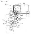
- the rotor drive member 31 is structured such that, as shown in Figs. 10 to 12 , a drive motor 33 and a rotating plate 34 are provided on a guide plate 32 fixed onto the collecting lifter 47, and a power transmission gear 34e is rotated by a drive gear 33a provided on a rotating shaft of the drive motor 33 through intermediate gears 34a, 34b, 34c, 34d provided on the rotating plate 34.
- the rotating plate 34 is fixed together with the intermediate gear 34a onto the guide plate 32 rotatably around a spindle 35.
- the intermediate gear 34c incorporates a one-way clutch which allows power transmission only when the drive motor 33 is reversely driven and rotated in one direction (rotated in an arrow a direction in Fig.
- the rotating plate 34 can be rotated to a retreat position ( Fig. 10 ) in almost the horizontal direction and to a standby position ( Fig. 11 ) in obliquely downward direction.
- the retreat position can be identified and the drive motor 33 can be stopped.
- the standby position can be identified and the drive motor 33 can be stopped. Further, in the case where the drive motor 33 is driven in the forward direction, power is not transmitted from the intermediate gear 34c to the rotating plate 34 and so the rotating plate 34 is positioned at a drive position ( Fig.
- the power transmission gear 34e engages with the driven gear 5a of the rotor 5, and driving force of the drive motor 33 acts as force to rotate the driven gear 5a or the rotor 5 through the respective gears 33a, 34a, 34b, 34c, 34d and 34e.
- the power transmission gear 34e engages with the driven gear 5a of the rotor 5 on the lower side of the rotation center. Consequently, the rotation direction of the rotating plate 34 conforms to the direction of engagement with the driven gear 5a, so that the power transmission state is stabilized.
- the rotating plate 34 itself can freely rotate, and so if the power transmission gear 34e does not properly engage with the gear 5a of the rotor 5, the proper engagement state can be earned by rotation of the rotating plate 34 and the resultant rotation of the power transmission gear 34e.
- the collecting lifter 47 has a lifter casing part 47a whose bottom face is composed of a bottom plate 48 and a fallout height absorber plate 50 which are rotatably linked to each other by a hinge 49 for collecting injection medicines dispensed from the cassette 2 through the rotor 21.
- the bottom plate 48 rotates through a gear 52 by driving of an open/close motor 51. Since the fallout height absorber plate 50 is linked to a free end edge part of the bottom plate 48 rotatably around the hinge 49 as described above, it rotates along the top face of the collecting conveyer 63.
- the fallout height absorber plate 50 is constituted of a sponge, a brush or the like which itself has an elastic deformation property, the linkage by the hinge 49 is not necessary.
- a solenoid 88 is provided above the collecting lifter 47.
- the collecting lifter 47 is linked to a timing belt 56 hung over upper and lower pulleys through a lifting support part 54, and moves up and down along a guide rail 53 by driving of a lifting motor 59.
- reference numeral 57 denotes a weight for achieving weight balance against the collecting lifter 47.
- the transportation conveyer unit 60 has a collecting conveyer 63 and a center conveyer 62.
- the collecting conveyer 63 is driven by a collecting conveyer drive motor 65 for transporting injection medicines to the center conveyer 62.
- the center conveyer 62 further transports the injection medicines transported from the collecting conveyer 63 to a transfer unit 61.
- a force shutter belt 66 and a force shutter 67 rotating together with the force shutter belt 66 are provided above the center conveyer 62. It is to be noted that the arrange of the collecting conveyer 63 and the center conveyer 62 in the transportation conveyer unit 60 is as shown in Fig. 14 .
- a display part 8 carrying contained medicine number, medicine name and capacity is provided on the front face of each cassette 2.
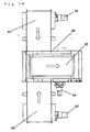
- an operation panel 200 and display panels 300 disposed for each column of the cassettes 2 are provided on the front upper portion of the dispensing device body 1.
- the operation panel 200 has, as shown in Fig. 15 , a start button, a stop button, a medicine collecting button and a cancel button, as well as LEDs each indicating Online, Error and Stock-Out.
- the display panel 300 carries a cassette No., an error LED and a Stock-Out LED. When the Online LED is lit on the operation panel 200, operation is available.
- the cassette 2 When medicines D are supplied to a cassette 2, the cassette 2 is dismounted from the stock shelf 3 of the dispensing device body 1.
- the stopper cancel member 13 is protruded in the horizontal direction by biasing force from the spring 14, by which the stopper 10 is rotated in the horizontal direction. Consequently, the medicines D in the cassette 2 are prevented from falling out by the fallout prevention part 12 in the stopper 10.
- the gear part 23 of the rotor 21 disengages from the recess parts 17a in the stopping rack 17, so as to prevent the movement to be hindered.
- the rotor 21 rotates through the operation part 22 and the engagement state between the gear part 23 and the stopping rack 17 is cancelled. In this case, if an interval is present between the push-out unit 18 and the medicine D, the push-out unit 18 slowly comes near the medicine D with the function of the oil damper 25 linked to the auxiliary gear 24 and arrays the medicine D without damaging it.
- the stopper cancel member 13 pushes the contact piece 13a with the protrusion 4, by which the stopper 10 rotates in the obliquely downward direction to prepare the medicine D to be discharged. In this state, the medicine D abuts against the outer circumferential plane 5c of the rotor 5.
- the collecting lifter 47 moves to the cassette 2 containing a pertinent medicine D based on the prescription data, and the dispensing unit 30 is driven to rotate the rotor 5 in the stock shelf 3. More particularly, the drive motor 33 is driven to rotate the rotor 5 through the gears 33a, 34a, 34b, 34c, 34d, 34e, 5a. As a result, the medicines D in the cassette 2 are dispensed in sequence one by one. The dispensed medicine D is collected by the collecting lifter 47 and transferred to the transportation conveyer unit 60, before being dispensed to the dispensing outlet 1a on the lower front face of the dispensing device body 1 through an unshown transfer unit.
- the rotor 5 may be structured so as to be integrated with the cassette 2 as shown in Fig. 19 and Fig. 20 . More particularly, a rotor mounting part 400 may be formed on the rear end side of the cassette 2, and the rotor 5 may be rotatably mounted through a through hole 401 formed on its lateral side. As described before, the center of rotation of the rotor 5 is positioned above the center of a discharge route of medicines, and the circular plane 5b is in the shape which allows dispensing of only one medicine D even if the medicine D has a maximum outer diameter and which prevents interference with the next medicine D. Further, the bottom face of the rotor mounting part 400 serves as an escape part 410 positioned below the bottom face of the cassette 2. From both sides of the stopping rack 17, a plate spring 411 is extensively provided.
- the plate spring 411 comes into tight contact with a head medicine received by the circular plane 5b of the rotor 5 to prevent the medicine D from falling out.
- the plate spring 411 comes into tight contact with the medicine D so that the medicine D can be retained by the circular plane 5b of the rotor 5 even if the medicine D has a smallest outer diameter.
- the plate spring 411 is elastically deformed so as to be within the escape part 410, by which the medicine D can be dispensed by the rotor 5. This allows the rotors 5 of the same shape to be used in any cassettes 2 which respectively contain medicines D different in outer diameter size.
- the end of the plate spring 411 should preferably be curved upward at a predetermined angle as shown in Fig. 25A . This allows more effective prevention of the medicines D contained in the cassette 2 from improperly popping out. In this case, what is necessary is to impart elasticity to the medicines D so that an edge E of the circular plane 5b of the rotor 5 is not positioned above a straight line S connecting the center of rotation O1 of the rotor 5 and the center 02 of the next medicine D by the end curved portion of the plate spring 411. Consequently, even if the rotor 5 rotates, the next medicine D is not pushed back by its outer circumferential plane 5c and so is free from influence of unnecessary load, thereby enabling the rotor 5 to smoothly rotate.
- the plate spring 411 may be provided on the ceiling face as shown in Fig. 25B instead on the bottom face of the cassette 2. In this case, the rotor 5 should be rotated in the reverse direction (counterclockwise in Fig. 25B ).
- a part of the rotor 5 including the circular plane 5b may be constituted of a pressing member 520, as shown in Fig. 25C , which is elastically supported in such a way as to be pushed down, so that the different size of the medicine D can be supported.
- the pressing member 520 is elastically supported in such a way as to be pushed down by a spring 521 provided at six places from an initial position shown in Fig. 25E to a pushed position shown in Fig. 25F .
- the stopping part 9 provided on the cassette 2 may be replaced with a stopping member 402 provided on the side of the stock shelf 3 as shown in Figs. 21 to 24 .
- a stopping recess part 406 should be formed on the lateral face of the cassette 2 and a stopping member 402 should be disposed on the side of the stock shelf 3.
- a component constituted so as to have a stopping part 405 which pushes a push part 404 to the side of a body 403 and protrudes to the lateral side upon mounting of the cassette 2 on the stock shelf 3 may be used.
- reference numeral 407 denotes a spring, and its one end portion is stopped by a stopping piece protruding from the bottom face of the stock shelf 3 while the other end potion is stopped by one end portion of a rod provided slidably on the bottom face of the stock shelf 3.
- the biasing force of the spring 407 acts through the rod so as to protrude the cassette 2 from the front face of the dispensing device body 1.
- the biasing force of the spring (wire diameter, winding number, length, etc.) is determined in consideration of the size and the weight of the cassette 2 contained in the stock shelf 3 or the protruding size of the cassette 2 from the stock shelf 3 and the like.
- the gear 5a provided on the rotor 5 may be engaged with a major diameter gear 501b of an intermediate gear 501, its minor gear 501a may be engaged with a rack gear 500, and the rack gear 500 may be reciprocated so as to rotate the rotor 5 in the reciprocal direction.
- a pressure receiving piece 500a for allowing easy pressing is provided on one end portion of the rack gear 500.
- a spring 502 is disposed so that the rack gear 500 is biased in a protruding direction from the cassette 2.
- the number of teeth of the major diameter gear 501b of the intermediate gear 501 is set at 20
- the number of teeth of the minor gear 501a is set at 14. Consequently, only by setting the amount of the rack gear 500 at 16mm, the rotor 5 can be rotated 240 degrees, i.e., the rotor 5 can be rotated desired angles with a short stroke.
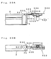
- the gear 5a provided on the rotor 5 may be engaged with a first gear 510 which operates in such a way as to come into contact or break away as shown in Fig. 27A .
- the first gear 510 is supported by a support piece 512 formed in laterally-positioned U shape which is provided on the end of a rod 511, and is rotated by driving of a motor 513 fixed to the support piece 512.
- the rod is attached to the end of a support body 514 in the state of being biased in the protruding direction by a spring 515.
- the support body 514 is guided at four places on its lateral faces by rotatable rollers 516 so as to be able to reciprocate.
- a rack 517 is formed, and the rack 517 is engaged with a second gear 519 provided on a rotating shaft of a forward/backward driving motor 518.
- the support body 514 moves forward and backward through the second gear 519 and the rack 517 as shown in Fig. 27B and Fig. 27C , and the first gear 510 comes into contact with or breaks away from the gear 5a of the rotor 5.
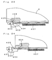
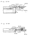
- the gear 5a provided on the rotor 5 may be engaged with a rack gear 521 biased in the protruding direction by a spring 520, and the rotor 5 may be rotated by pressing an end portion of the rack gear with a pusher 522.
- the pusher 522 is structured such that a rack gear 524 is slidably disposed on the pusher body 523 and a pusher rod 525 is fixed onto the end of the rack gear 524.
- the rack gear 524 is engaged with a drive gear 527 integrated with a rotating shaft of a motor 526, and is slid by driving of the motor 526.
- Sensors 528a, 528b, 528C provided at three places on the rack gear 524 detect a protruding position at which the rack gear 521 is pushed by the pusher rod 525 (see Fig. 28A and Fig. 28B ), a standby position before the pusher rod 525 is protruded (see Fig. 28C ), and an avoiding position for avoiding interference with the bottom plate 48 when the bottom plate 48 of the collecting lifter 47 is opened.
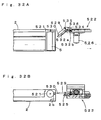
- the pusher 522 may be constituted to have a stopping/retaining member 529.
- the stopping/retaining member 529 is in a plate-like shape, and a stopping hook part 530 is protruded on its one end side.
- the stopping hook part 530 is narrower than the stopping/retaining member 529.
- the end of the stopping hook part 530 is curved toward the lateral direction, and is engaged with a stopping hole 2b formed on the rear lateral face of the cassette 2.
- the stopping/retaining member 529 has an inclined piece 531 extensively provided on the other end side, the inclined piece 531 being inclined gradually toward the end. Further, the stopping/retaining member 529 has a long hole 532 formed along a lateral edge portion from the inclined piece 531 toward the vicinity of the stopping hook part 530.
- the stopping/retaining member 529 is linked to a support piece 534 extensively provided on the pusher body 523 so as to be rotatable around a spindle 535. Moreover, a guide pin 536 protruding from the upper face of the rack gear 521 is slidable in the long hole 532 on the stopping/retaining member 529.
- the stopping/retaining member 529 is rotated to a protruding position along the rack gear 521 as shown in Figs. 30A and 30B , and at this protruding position, the stopping hook part 530 may be stopped by the stopping hole 2b of the cassette 2.
- the stopping/retaining member 529 is rotated to a retreat position inclined to the rack gear 521 as shown in Figs. 32A and 32B .
- the stopping/retaining member 529 will not interfere with the cassette 2.
- the guide pin 536 slides from the inclined part 532b to the straight line part 532a of the long hole 532 with the forward movement as shown in Figs. 30A and 30B , and the stopping/retaining member 529 rotates around the spindle 535 from the retreat position to the protruding position. Consequently, the stopping hook part 530 is stopped by the stopping hole 2b of the cassette 2 in a locked state, which prevents the cassette 2 during dispensing processing from dismounting from the stock shelf 3.
- the motor 526 is driven for reciprocal rotation, so that the rack gear 524 is reciprocated and the rack gear 521 is pressed specified times by the pusher rod 525 according to the prescription data, by which the rotor 5 is rotated to dispense a specified quantity of medicines.
- the guide pin 536 reciprocates in the straight line part 532a of the long hole 532 so that the locked state by the stopping/retaining member 529 is maintained.
- the motor 526 is driven to rotate in the reverse direction so as to move the rack gear 524 backward as shown in Figs. 32A and 32B .
- the guide pin 536 slides from the straight line part 532a to the inclined part 532b of the long hole 532, and the stopping/retaining member 529 rotates to the retreat position. Consequently, the stopping hook part 530 is disengaged from the stopping hole 2b of the cassette 2, which allows the cassette 2 to be dismounted from the stock shelf 3.
- the stopping/retaining member 529 to the pusher 522, it is not necessary to impart the locking mechanism to each of the stock shelves 3, which can prevent such failure that the cassette 2 during dispensing processing is dismounted and medicines D remain in the device. Further, since only the cassette 2 during dispensing processing can be locked, operation to charge other cassettes 2 with medicines can be performed, making it possible to enhance workability. Further, providing the locking mechanism to the respective stock shelves 3 requires on/off control in the respective mechanisms, thereby causing cost increase. However, in the present embodiment, the simple constitution of the stopping/retaining member 529 provided to the pusher 522 allows cost reduction.
Landscapes
- Physics & Mathematics (AREA)
- General Physics & Mathematics (AREA)
- Health & Medical Sciences (AREA)
- Chemical & Material Sciences (AREA)
- Medicinal Chemistry (AREA)
- Pharmacology & Pharmacy (AREA)
- Life Sciences & Earth Sciences (AREA)
- Animal Behavior & Ethology (AREA)
- General Health & Medical Sciences (AREA)
- Public Health (AREA)
- Veterinary Medicine (AREA)
- Medical Preparation Storing Or Oral Administration Devices (AREA)
- Warehouses Or Storage Devices (AREA)
Claims (10)
- Vorrichtung zur Ausgabe von Medikamenten, mit:einem Ausgabevorrichtungsgehäuse (1), einer lösbar an dem Ausgabevorrichtungskörper (1) angebrachten Kassette (2) zum Aufnahmen von Medikamenten während des Anordnens derselben, und einer Schiebeeinrichtung (18) zum Herausschieben der in der Kassette (2) enthaltenen Medikamente in Richtung einer Stirnseite,wobei die Kassette (2) eine Abdeckung zum Anordnen der enthaltenen Medikamente und ein im Inneren in Längsrichtung angeordnetes Stopp-/Aufnahmeteil (17) aufweist, undwobei die Schiebeeinrichtung (18) ein Anlageteil, das in der Kassette (2) enthalten ist und an den Medikamenten anliegt, und ein Vorspannteil (20) zum Vorspannen des Anlageteils gegen die Medikamente aufweist, um die Medikamente von einer Stirnseite her zu drücken und anzuordnen,dadurch gekennzeichnet, dassdie Schiebeeinrichtung (18) ein Stoppteil (21) aufweist, das an dem Stopp-/Aufnahmeteil (17) der Kassette (2) nur dann stoppt, wenn die Abdeckung geöffnet ist, so dass das Anlageteil daran gehindert ist, die Medikamente entsprechend der Vorspannkraft des Vorspannteils (20) zu drücken, wobei, wenn die Schiebeeinrichtung bewegt wird, das Stoppteil (21) von dem Stopp-/Aufnahmeteil (17) gelöst ist und das Anlageteil in eine beliebige Position bewegt wird, um das Positionieren der Medikamente zu ermöglichen.
- Vorrichtung zur Ausgabe von Medikamenten nach Anspruch 1, bei welcher die Schiebeeinrichtung (18) derart ausgebildet ist, dass das Vorspannteil (20) und das Stoppteil (21) in einem Gehäuse (19) aufgenommen sind und eine Stirnseite (19a) des Gehäuses als das Anlageteil dient.
- Vorrichtung zur Ausgabe von Medikamenten nach Anspruch 1, bei welcher die Kassette (2) eine Herausfallen verhindernde Einrichtung (10) aufweist, um in dem Fall, dass die Kassette (2) aus dem Ausgabevorrichtungsgehäuse (1) ausgebaut ist, das Herausfallen von enthaltenen Medikamenten zu verhindern, und
das Ausgabevorrichtungsgehäuse (1) ein Aufhebungsteil (13) zum Aufheben der Herausfallverhinderung durch die Einrichtung zum Verhindern des Herausfallens bei eingebauter Kassette (2) und ein Ausgabeteil aufweist, welches ermöglicht, die in der Kassette (2) befindlichen Medikamente einzeln auszugeben. - Vorrichtung zur Ausgabe von Medikamenten nach Anspruch 1, bei welcher das Stopp-/Aufnahmeteil (17) aus einer Stopp-Zahnschiene (17) besteht, die aus mehreren Ausnehmungsteilen (17a) gebildet ist, welche in Längsrichtung der Kassette (2) nebeneinanderliegend angeordnet sind, und das Stoppteil (21) ein Zahnrad (23) aufweist, das in Reaktion auf das Öffnen und das Schließen der Abdeckung dreht, um mit der Stopp-Zahnschiene (17) zusammenzugreifen.
- Vorrichtung zur Ausgabe von Medikamenten nach Anspruch 4, bei welcher das Schiebeteil (18) ein mit der Stopp-Zahnschiene (17) zusammengreifendes Hilfszahnrad (24) und einen in dem Hilfszahnrad (24) integrierten Öldämpfer aufweist, und das Vorspannteil (20) aus einer Dauerlastfeder (20) besteht.
- Vorrichtung zur Ausgabe von Medikamenten nach Anspruch 3, bei welcher das Ausgabeteil aus einem Rotor (5) mit einer kreisförmigen Ebene (5b) gebildet ist, welche es ermöglicht, Medikamente einzeln zu halten, wobei der Rotor (5) mittels Energie angetrieben ist, welche über ein auf einer Drehwelle vorgesehenes Zahnrad (519) übertragen wird, wobei das Zahnrad (519) mit einer auf einer Stange (511) ausgebildeten Zahnschiene (517) zusammengreift, wobei die Stange (511) hin- und hergehend bewegbar ist.
- Vorrichtung zum Ausgeben von Medikamenten nach Anspruch 3, bei welcher das Ausgabeteil aus einem Rotor (5) mit einer kreisförmigen Ebene (5b) gebildet ist, welche es ermöglicht, Medikamente einzeln zu halten, wobei der Rotor (5) mittels Energie angetrieben ist, welche über ein auf einer Drehwelle vorgesehenes Antriebszahnrad (33a) übertragen wird, wobei das Antriebszahnrad (33a) über Zahnräder (34a-d) in Eingriff mit einem drehend antreibenden Kraftübertragungszahnrad (34e) ist, wobei das Kraftübertragungszahnrad (34e) in der Lage ist, mit dem Zahnrad (5a) jedes Rotors (5) der mehreren Kassetten (2) in Kontakt zu gelangen oder sich von diesen zu lösen.
- Vorrichtung zum Ausgeben von Medikamenten nach Anspruch 3, bei welcher die ein Herausfallen verhindernde Einrichtung aus einer an einer Endöffnung der Kassette (2) vorgesehenen Tellerfeder (411) besteht, wobei die Tellerfeder (411) aus einer Herausfallverhinderungsposition zum Verhindern des Herausfallens von Medikamenten aus den Kassetten (2) in eine Medikamentenausgabeposition zum Ermöglichen der Ausgeb von Medikamenten durch das Ausgabeteil elastisch verformbar ist.
- Vorrichtung zum Ausgeben von Medikamenten nach Anspruch 8, bei welcher die Tellerfeder (411) das vordere Medikament elastisch stützt, so dass die Position des nächsten Medikaments nicht verändert wird, wenn das auf der kreisförmigen Ebene (5b) des Rotors (5) aufgenommene vordere Medikament durch Drehen des Rotors (5) aus der Kassette (2) ausgegeben wird.
- Vorrichtung zum Ausgeben von Medikamenten nach Anspruch 3, bei welcher das Ausgabevorrichtungsgehäuse (1) einen Stößel (522), der das Ausgabeteil der Kassette (2) zur Ausgabe von Medikamenten antreibt, und ein Stopp-/Rückhalteelement (529) aufweist, das mit dem Stößel (522) verzahnt ist, um an der Kassette (2) anzugreifen oder sich von dieser zu lösen.
Applications Claiming Priority (5)
| Application Number | Priority Date | Filing Date | Title |
|---|---|---|---|
| JP2002305165 | 2002-10-18 | ||
| JP2002305165 | 2002-10-18 | ||
| JP2003088292 | 2003-03-27 | ||
| JP2003088292 | 2003-03-27 | ||
| PCT/JP2003/007241 WO2004034955A1 (ja) | 2002-10-18 | 2003-06-09 | 薬剤払出装置 |
Publications (3)
| Publication Number | Publication Date |
|---|---|
| EP1552805A1 EP1552805A1 (de) | 2005-07-13 |
| EP1552805A4 EP1552805A4 (de) | 2007-10-03 |
| EP1552805B1 true EP1552805B1 (de) | 2013-04-24 |
Family
ID=32109490
Family Applications (1)
| Application Number | Title | Priority Date | Filing Date |
|---|---|---|---|
| EP03733317.6A Expired - Lifetime EP1552805B1 (de) | 2002-10-18 | 2003-06-09 | Vorrichtung zur abgabe von medikamenten |
Country Status (9)
| Country | Link |
|---|---|
| US (1) | US7316328B2 (de) |
| EP (1) | EP1552805B1 (de) |
| JP (1) | JP4343902B2 (de) |
| KR (1) | KR100964720B1 (de) |
| CN (1) | CN100372518C (de) |
| CA (1) | CA2502506A1 (de) |
| NO (1) | NO20052374L (de) |
| TW (1) | TWI295573B (de) |
| WO (1) | WO2004034955A1 (de) |
Families Citing this family (49)
| Publication number | Priority date | Publication date | Assignee | Title |
|---|---|---|---|---|
| WO2006025347A1 (ja) * | 2004-08-31 | 2006-03-09 | National University Corporation Tohoku University | 銅合金及び液晶表示装置 |
| TWI290898B (en) * | 2002-08-05 | 2007-12-11 | Yuyama Mfg Co Ltd | Feeding device of drug |
| JP4421920B2 (ja) * | 2003-09-26 | 2010-02-24 | 株式会社湯山製作所 | 薬品払出装置 |
| CN1976670B (zh) * | 2004-05-19 | 2011-10-26 | 株式会社汤山制作所 | 药品分配装置 |
| JP4502374B2 (ja) * | 2004-05-19 | 2010-07-14 | 高園産業株式会社 | 薬品収納用カセット及び薬品収納装置 |
| JP4601386B2 (ja) * | 2004-10-15 | 2010-12-22 | 株式会社湯山製作所 | 薬剤カート |
| JP4520814B2 (ja) | 2004-10-15 | 2010-08-11 | 株式会社湯山製作所 | 薬品払出装置 |
| JP4992262B2 (ja) * | 2005-09-30 | 2012-08-08 | 株式会社湯山製作所 | 薬剤払出装置 |
| JP4961791B2 (ja) * | 2006-03-27 | 2012-06-27 | 株式会社湯山製作所 | 薬剤カート |
| KR100744427B1 (ko) * | 2006-06-05 | 2007-08-01 | (주)제이브이엠 | 약제자동포장장치용 카세트 인식장치 및 그 방법 |
| EP2229664A1 (de) * | 2007-06-28 | 2010-09-22 | Davide Maria Consolaro | Produktverkaufsmaschine |
| US8271128B1 (en) | 2008-07-30 | 2012-09-18 | Kirby Lester, Llc | Pharmacy workflow management system including plural counters |
| JP5434420B2 (ja) | 2008-09-19 | 2014-03-05 | 株式会社湯山製作所 | 薬剤払出装置及び薬剤払出方法 |
| TWI485093B (zh) * | 2008-11-21 | 2015-05-21 | Yuyama Mfg Co Ltd | Lozenge delivery device |
| WO2010101095A1 (ja) * | 2009-03-01 | 2010-09-10 | 株式会社湯山製作所 | 薬箱払出装置 |
| JP5062915B2 (ja) * | 2010-03-09 | 2012-10-31 | 高園産業株式会社 | 薬品収納装置 |
| JP5940162B2 (ja) * | 2011-11-08 | 2016-06-29 | アイシッシュ ヘルスケア システム,エス.エル. | 単位用量の薬を保管するためのチューブ、チューブに注入し、チューブを用いてキャビネットに分配するための方法および装置 |
| JP5355748B2 (ja) * | 2012-05-29 | 2013-11-27 | 高園産業株式会社 | 薬品収納装置 |
| US9511945B2 (en) | 2012-10-12 | 2016-12-06 | Aesynt Incorporated | Apparatuses, systems, and methods for transporting medications from a central pharmacy to a patient in a healthcare facility |
| US9150119B2 (en) | 2013-03-15 | 2015-10-06 | Aesynt Incorporated | Apparatuses, systems, and methods for anticipating and delivering medications from a central pharmacy to a patient using a track based transport system |
| JP6316199B2 (ja) * | 2012-11-01 | 2018-04-25 | Phcホールディングス株式会社 | 薬剤収納カセットと、それを装着する薬剤払出装置 |
| CN103144902B (zh) * | 2012-12-17 | 2015-08-12 | 苏州艾隆科技股份有限公司 | 针剂分配机 |
| CN103144901B (zh) * | 2012-12-17 | 2015-08-12 | 苏州艾隆科技股份有限公司 | 针剂分配盒及具有其的针剂分配机 |
| KR102049273B1 (ko) * | 2013-02-13 | 2020-01-08 | (주)제이브이엠 | 약제 불출 유닛 및 이를 포함하는 약제 불출 장치 |
| CN103373573B (zh) * | 2013-07-11 | 2016-06-15 | 深圳市安瑞科科技有限公司 | 智能针剂储药装置 |
| CN103332425B (zh) * | 2013-07-15 | 2016-09-14 | 苏州艾隆科技股份有限公司 | 发药机的出药结构及具有其的发药机 |
| US9984525B2 (en) * | 2014-04-24 | 2018-05-29 | The Hillman Group, Inc. | Automated vending inventory management apparatuses and method |
| WO2016120611A2 (en) * | 2015-01-28 | 2016-08-04 | The Heartbeat Manufacturing Co (Redditch) Limited | Shelf management device |
| US10669091B2 (en) * | 2015-03-06 | 2020-06-02 | International Business Machines Corporation | Automated health product dispensary library |
| CN105151625B (zh) * | 2015-08-17 | 2017-06-23 | 江苏达瑞医疗科技有限公司 | 一种发药自动控制盒 |
| CA2939591C (en) | 2015-08-25 | 2021-11-09 | Chudy Group, LLC | Plural-mode automatic medicament packaging system |
| CN105819135B (zh) * | 2015-10-28 | 2018-01-26 | 上海博信机器人科技有限公司 | 一种自动分药盒机构 |
| CN106144378B (zh) * | 2016-06-29 | 2018-09-14 | 苏州信亨自动化科技有限公司 | 瓶装药剂自动发药装置 |
| CN106327690B (zh) * | 2016-08-25 | 2022-06-17 | 苏州艾隆科技股份有限公司 | 自动售药机 |
| CN106340124A (zh) * | 2016-08-29 | 2017-01-18 | 桐庐中浩塑料机械有限公司 | 自动售笔机 |
| EP3861891B1 (de) * | 2016-12-12 | 2024-01-31 | SMARK GmbH | Lager- und kommissioniersystem |
| TWI662960B (zh) * | 2017-10-05 | 2019-06-21 | 許敏倉 | 攜帶式餵藥盒 |
| JP2019076570A (ja) * | 2017-10-26 | 2019-05-23 | Phcホールディングス株式会社 | 薬品排出装置およびこれを備えた薬品仕分装置、薬品払出システム |
| CN108190338A (zh) * | 2018-01-17 | 2018-06-22 | 苏州市厚宏智能科技有限公司 | 自动发药机 |
| US11482325B2 (en) | 2019-06-25 | 2022-10-25 | Scientia Potentia Est., LC | System for verification and management of medical objects |
| CN112237352B (zh) * | 2020-09-15 | 2021-12-10 | 昊天行医学科技(北京)股份有限公司 | 基于大数据可流动中医药智能药房系统 |
| CN112530084B (zh) * | 2020-11-20 | 2022-06-07 | 威海新北洋数码科技有限公司 | 自动售货机和补货方法 |
| CN112471949B (zh) * | 2020-12-11 | 2022-05-17 | 内蒙古工业大学 | 火灾应急防护湿巾装置 |
| CN113044456B (zh) * | 2021-03-12 | 2022-08-23 | 北京华兴长泰物联网技术研究院有限责任公司 | 一种可拉出的补药机构、出药、售药机及其控制方法 |
| CN113306940B (zh) * | 2021-06-30 | 2025-02-07 | 苏州英特吉医疗设备有限公司 | 一种智能化自助药房 |
| CN113808333B (zh) * | 2021-09-17 | 2022-09-30 | 顾志波 | 一种可移动式运输手术材料机器人 |
| CN114748777B (zh) * | 2022-05-10 | 2024-10-25 | 徐浩东 | 一种烧伤科用药膏涂抹装置 |
| CN115838029B (zh) * | 2023-02-24 | 2023-05-16 | 江苏环亚医用科技集团股份有限公司 | 一种用于药品输送的机器人 |
| CN117775572B (zh) * | 2024-01-02 | 2026-03-31 | 江苏达实久信数字医疗科技有限公司 | 一种安瓿瓶管控药品智能发药装置 |
Family Cites Families (15)
| Publication number | Priority date | Publication date | Assignee | Title |
|---|---|---|---|---|
| US3777931A (en) * | 1971-03-18 | 1973-12-11 | Fort Howard Paper Co | Dispenser with spring-urged, automatic-stop pressure plate |
| US5263596A (en) * | 1991-12-02 | 1993-11-23 | Williams David R | Medication dispenser station sub-assembly |
| JP3170579B2 (ja) | 1994-04-18 | 2001-05-28 | 株式会社エム・シー・エー | アンプル払い出し装置 |
| CA2241082C (en) | 1995-12-29 | 2005-11-08 | Janice Fant Gilmore | Automatic medicament dispenser system |
| JP2000024085A (ja) | 1998-07-14 | 2000-01-25 | Tosho:Kk | 調剤用薬剤払出装置 |
| JP2000072204A (ja) | 1998-09-01 | 2000-03-07 | Matsushita Electric Ind Co Ltd | 注射薬自動払出装置 |
| JP2000255717A (ja) | 1999-03-10 | 2000-09-19 | Matsushita Electric Ind Co Ltd | 製品の残数管理方法および製品取出装置 |
| US6189727B1 (en) * | 1999-03-24 | 2001-02-20 | S&S X-Ray Products, Inc. | Pharmaceutical dispensing arrangement |
| US6370841B1 (en) * | 1999-12-03 | 2002-04-16 | Automed Technologies, Inc. | Automated method for dispensing bulk medications with a machine-readable code |
| JP4462689B2 (ja) * | 2000-01-18 | 2010-05-12 | 株式会社トーショー | 薬品収納装置 |
| EP2319479A1 (de) | 2000-03-28 | 2011-05-11 | Yuyama Mfg. Co., Ltd. | Abgabevorrichtung für einspritzbare Medikamente |
| WO2003074396A1 (en) * | 2002-03-04 | 2003-09-12 | Alexandre Maldonado | Adjustable push forward dispensing mechanism |
| JP4462726B2 (ja) | 2000-06-29 | 2010-05-12 | 株式会社トーショー | 薬品収納装置 |
| JP4467850B2 (ja) | 2001-09-14 | 2010-05-26 | パナソニック株式会社 | 注射薬自動払出装置 |
| JP4380190B2 (ja) | 2003-03-18 | 2009-12-09 | 株式会社トーショー | 薬品払出装置 |
-
2003
- 2003-06-06 TW TW092115373A patent/TWI295573B/zh active
- 2003-06-09 CA CA002502506A patent/CA2502506A1/en not_active Abandoned
- 2003-06-09 KR KR1020057000988A patent/KR100964720B1/ko not_active Expired - Fee Related
- 2003-06-09 EP EP03733317.6A patent/EP1552805B1/de not_active Expired - Lifetime
- 2003-06-09 JP JP2005501340A patent/JP4343902B2/ja not_active Expired - Fee Related
- 2003-06-09 CN CNB038166917A patent/CN100372518C/zh not_active Expired - Fee Related
- 2003-06-09 WO PCT/JP2003/007241 patent/WO2004034955A1/ja not_active Ceased
- 2003-06-09 US US10/531,581 patent/US7316328B2/en not_active Expired - Fee Related
-
2005
- 2005-05-13 NO NO20052374A patent/NO20052374L/no not_active Application Discontinuation
Also Published As
| Publication number | Publication date |
|---|---|
| NO20052374D0 (no) | 2005-05-13 |
| KR100964720B1 (ko) | 2010-06-21 |
| EP1552805A1 (de) | 2005-07-13 |
| EP1552805A4 (de) | 2007-10-03 |
| US20060097001A1 (en) | 2006-05-11 |
| JP4343902B2 (ja) | 2009-10-14 |
| CN100372518C (zh) | 2008-03-05 |
| KR20050061440A (ko) | 2005-06-22 |
| CN1668267A (zh) | 2005-09-14 |
| CA2502506A1 (en) | 2004-04-29 |
| US7316328B2 (en) | 2008-01-08 |
| JPWO2004034955A1 (ja) | 2006-02-09 |
| TW200406191A (en) | 2004-05-01 |
| WO2004034955A1 (ja) | 2004-04-29 |
| NO20052374L (no) | 2005-07-12 |
| TWI295573B (en) | 2008-04-11 |
Similar Documents
| Publication | Publication Date | Title |
|---|---|---|
| EP1552805B1 (de) | Vorrichtung zur abgabe von medikamenten | |
| US6328180B1 (en) | Apparatus and method for vending products | |
| US5480062A (en) | Vacuum operated medicine dispenser | |
| US6513677B1 (en) | Apparatus and method for vending products | |
| US7360668B2 (en) | Tablet packing apparatus | |
| US6581355B1 (en) | Tablet filling device | |
| US5832693A (en) | Apparatus for collecting ampules | |
| JP4259811B2 (ja) | 薬剤供給装置 | |
| JPWO2010101095A1 (ja) | 薬箱払出装置 | |
| JP2004510233A (ja) | カートリッジを装填した装置を使った集中管理式自動販売方法 | |
| JP4969677B2 (ja) | Ptp払出システム | |
| US10431035B2 (en) | Picking device and method for retrieving drug compositions from storage | |
| US20100251667A1 (en) | Vial lid fastening device and medicine accommodating and removing device | |
| CN100493994C (zh) | 药剂架的卷帘门装置 | |
| JP3170579B2 (ja) | アンプル払い出し装置 | |
| JP2011078600A (ja) | 自動薬剤供給装置 | |
| JP4614834B2 (ja) | Ptp払出システム | |
| JPH1083476A (ja) | 薬液入り容器供給装置 | |
| JP7025579B2 (ja) | 薬品排出装置およびこれを備えた薬品仕分装置、薬品払出システム | |
| JP4540558B2 (ja) | ボトルフィーダ及びボトル払出装置ならびに薬品類払出システム | |
| JP2005237713A (ja) | 薬品払出装置 | |
| JP2006146688A (ja) | 自動販売機 | |
| JPH06176261A (ja) | 自動販売機の商品収納部 | |
| CA2520414A1 (en) | Vacuum operated medicine dispenser | |
| JPH0665311U (ja) | 物品の格納払い出し装置 |
Legal Events
| Date | Code | Title | Description |
|---|---|---|---|
| PUAI | Public reference made under article 153(3) epc to a published international application that has entered the european phase |
Free format text: ORIGINAL CODE: 0009012 |
|
| 17P | Request for examination filed |
Effective date: 20050426 |
|
| AK | Designated contracting states |
Kind code of ref document: A1 Designated state(s): AT BE BG CH CY CZ DE DK EE ES FI FR GB GR HU IE IT LI LU MC NL PT RO SE SI SK TR |
|
| A4 | Supplementary search report drawn up and despatched |
Effective date: 20070904 |
|
| 17Q | First examination report despatched |
Effective date: 20100205 |
|
| RIC1 | Information provided on ipc code assigned before grant |
Ipc: G07F 11/38 20060101ALI20120313BHEP Ipc: A61J 7/00 20060101AFI20120313BHEP |
|
| REG | Reference to a national code |
Ref country code: DE Ref legal event code: R079 Ref document number: 60343879 Country of ref document: DE Free format text: PREVIOUS MAIN CLASS: A61J0003000000 Ipc: G07F0017000000 |
|
| GRAP | Despatch of communication of intention to grant a patent |
Free format text: ORIGINAL CODE: EPIDOSNIGR1 |
|
| RIC1 | Information provided on ipc code assigned before grant |
Ipc: G07F 11/38 20060101ALI20121026BHEP Ipc: G07F 11/16 20060101ALI20121026BHEP Ipc: G07F 17/00 20060101AFI20121026BHEP Ipc: A61J 7/00 20060101ALI20121026BHEP |
|
| GRAS | Grant fee paid |
Free format text: ORIGINAL CODE: EPIDOSNIGR3 |
|
| GRAA | (expected) grant |
Free format text: ORIGINAL CODE: 0009210 |
|
| AK | Designated contracting states |
Kind code of ref document: B1 Designated state(s): AT BE BG CH CY CZ DE DK EE ES FI FR GB GR HU IE IT LI LU MC NL PT RO SE SI SK TR |
|
| REG | Reference to a national code |
Ref country code: GB Ref legal event code: FG4D |
|
| REG | Reference to a national code |
Ref country code: CH Ref legal event code: EP |
|
| REG | Reference to a national code |
Ref country code: AT Ref legal event code: REF Ref document number: 609015 Country of ref document: AT Kind code of ref document: T Effective date: 20130515 |
|
| REG | Reference to a national code |
Ref country code: IE Ref legal event code: FG4D |
|
| REG | Reference to a national code |
Ref country code: DE Ref legal event code: R096 Ref document number: 60343879 Country of ref document: DE Effective date: 20130620 |
|
| REG | Reference to a national code |
Ref country code: NL Ref legal event code: T3 |
|
| REG | Reference to a national code |
Ref country code: AT Ref legal event code: MK05 Ref document number: 609015 Country of ref document: AT Kind code of ref document: T Effective date: 20130424 |
|
| PG25 | Lapsed in a contracting state [announced via postgrant information from national office to epo] |
Ref country code: SE Free format text: LAPSE BECAUSE OF FAILURE TO SUBMIT A TRANSLATION OF THE DESCRIPTION OR TO PAY THE FEE WITHIN THE PRESCRIBED TIME-LIMIT Effective date: 20130424 Ref country code: FI Free format text: LAPSE BECAUSE OF FAILURE TO SUBMIT A TRANSLATION OF THE DESCRIPTION OR TO PAY THE FEE WITHIN THE PRESCRIBED TIME-LIMIT Effective date: 20130424 Ref country code: BE Free format text: LAPSE BECAUSE OF FAILURE TO SUBMIT A TRANSLATION OF THE DESCRIPTION OR TO PAY THE FEE WITHIN THE PRESCRIBED TIME-LIMIT Effective date: 20130424 Ref country code: GR Free format text: LAPSE BECAUSE OF FAILURE TO SUBMIT A TRANSLATION OF THE DESCRIPTION OR TO PAY THE FEE WITHIN THE PRESCRIBED TIME-LIMIT Effective date: 20130725 Ref country code: SI Free format text: LAPSE BECAUSE OF FAILURE TO SUBMIT A TRANSLATION OF THE DESCRIPTION OR TO PAY THE FEE WITHIN THE PRESCRIBED TIME-LIMIT Effective date: 20130424 Ref country code: PT Free format text: LAPSE BECAUSE OF FAILURE TO SUBMIT A TRANSLATION OF THE DESCRIPTION OR TO PAY THE FEE WITHIN THE PRESCRIBED TIME-LIMIT Effective date: 20130826 Ref country code: ES Free format text: LAPSE BECAUSE OF FAILURE TO SUBMIT A TRANSLATION OF THE DESCRIPTION OR TO PAY THE FEE WITHIN THE PRESCRIBED TIME-LIMIT Effective date: 20130804 Ref country code: AT Free format text: LAPSE BECAUSE OF FAILURE TO SUBMIT A TRANSLATION OF THE DESCRIPTION OR TO PAY THE FEE WITHIN THE PRESCRIBED TIME-LIMIT Effective date: 20130424 |
|
| PG25 | Lapsed in a contracting state [announced via postgrant information from national office to epo] |
Ref country code: BG Free format text: LAPSE BECAUSE OF FAILURE TO SUBMIT A TRANSLATION OF THE DESCRIPTION OR TO PAY THE FEE WITHIN THE PRESCRIBED TIME-LIMIT Effective date: 20130724 Ref country code: CY Free format text: LAPSE BECAUSE OF FAILURE TO SUBMIT A TRANSLATION OF THE DESCRIPTION OR TO PAY THE FEE WITHIN THE PRESCRIBED TIME-LIMIT Effective date: 20130424 |
|
| PG25 | Lapsed in a contracting state [announced via postgrant information from national office to epo] |
Ref country code: EE Free format text: LAPSE BECAUSE OF FAILURE TO SUBMIT A TRANSLATION OF THE DESCRIPTION OR TO PAY THE FEE WITHIN THE PRESCRIBED TIME-LIMIT Effective date: 20130424 Ref country code: SK Free format text: LAPSE BECAUSE OF FAILURE TO SUBMIT A TRANSLATION OF THE DESCRIPTION OR TO PAY THE FEE WITHIN THE PRESCRIBED TIME-LIMIT Effective date: 20130424 Ref country code: DK Free format text: LAPSE BECAUSE OF FAILURE TO SUBMIT A TRANSLATION OF THE DESCRIPTION OR TO PAY THE FEE WITHIN THE PRESCRIBED TIME-LIMIT Effective date: 20130424 Ref country code: CZ Free format text: LAPSE BECAUSE OF FAILURE TO SUBMIT A TRANSLATION OF THE DESCRIPTION OR TO PAY THE FEE WITHIN THE PRESCRIBED TIME-LIMIT Effective date: 20130424 Ref country code: MC Free format text: LAPSE BECAUSE OF FAILURE TO SUBMIT A TRANSLATION OF THE DESCRIPTION OR TO PAY THE FEE WITHIN THE PRESCRIBED TIME-LIMIT Effective date: 20130424 |
|
| REG | Reference to a national code |
Ref country code: CH Ref legal event code: PL |
|
| PG25 | Lapsed in a contracting state [announced via postgrant information from national office to epo] |
Ref country code: RO Free format text: LAPSE BECAUSE OF FAILURE TO SUBMIT A TRANSLATION OF THE DESCRIPTION OR TO PAY THE FEE WITHIN THE PRESCRIBED TIME-LIMIT Effective date: 20130424 Ref country code: IT Free format text: LAPSE BECAUSE OF FAILURE TO SUBMIT A TRANSLATION OF THE DESCRIPTION OR TO PAY THE FEE WITHIN THE PRESCRIBED TIME-LIMIT Effective date: 20130424 |
|
| PLBE | No opposition filed within time limit |
Free format text: ORIGINAL CODE: 0009261 |
|
| STAA | Information on the status of an ep patent application or granted ep patent |
Free format text: STATUS: NO OPPOSITION FILED WITHIN TIME LIMIT |
|
| GBPC | Gb: european patent ceased through non-payment of renewal fee |
Effective date: 20130724 |
|
| REG | Reference to a national code |
Ref country code: IE Ref legal event code: MM4A |
|
| 26N | No opposition filed |
Effective date: 20140127 |
|
| PG25 | Lapsed in a contracting state [announced via postgrant information from national office to epo] |
Ref country code: LI Free format text: LAPSE BECAUSE OF NON-PAYMENT OF DUE FEES Effective date: 20130630 Ref country code: CH Free format text: LAPSE BECAUSE OF NON-PAYMENT OF DUE FEES Effective date: 20130630 Ref country code: GB Free format text: LAPSE BECAUSE OF NON-PAYMENT OF DUE FEES Effective date: 20130724 Ref country code: IE Free format text: LAPSE BECAUSE OF NON-PAYMENT OF DUE FEES Effective date: 20130609 |
|
| REG | Reference to a national code |
Ref country code: DE Ref legal event code: R097 Ref document number: 60343879 Country of ref document: DE Effective date: 20140127 |
|
| PGFP | Annual fee paid to national office [announced via postgrant information from national office to epo] |
Ref country code: NL Payment date: 20140618 Year of fee payment: 12 Ref country code: DE Payment date: 20140619 Year of fee payment: 12 |
|
| PGFP | Annual fee paid to national office [announced via postgrant information from national office to epo] |
Ref country code: FR Payment date: 20140619 Year of fee payment: 12 |
|
| PG25 | Lapsed in a contracting state [announced via postgrant information from national office to epo] |
Ref country code: TR Free format text: LAPSE BECAUSE OF FAILURE TO SUBMIT A TRANSLATION OF THE DESCRIPTION OR TO PAY THE FEE WITHIN THE PRESCRIBED TIME-LIMIT Effective date: 20130424 |
|
| PG25 | Lapsed in a contracting state [announced via postgrant information from national office to epo] |
Ref country code: LU Free format text: LAPSE BECAUSE OF NON-PAYMENT OF DUE FEES Effective date: 20130609 Ref country code: HU Free format text: LAPSE BECAUSE OF FAILURE TO SUBMIT A TRANSLATION OF THE DESCRIPTION OR TO PAY THE FEE WITHIN THE PRESCRIBED TIME-LIMIT; INVALID AB INITIO Effective date: 20030609 |
|
| REG | Reference to a national code |
Ref country code: DE Ref legal event code: R119 Ref document number: 60343879 Country of ref document: DE |
|
| REG | Reference to a national code |
Ref country code: NL Ref legal event code: MM Effective date: 20150701 |
|
| REG | Reference to a national code |
Ref country code: FR Ref legal event code: ST Effective date: 20160229 |
|
| PG25 | Lapsed in a contracting state [announced via postgrant information from national office to epo] |
Ref country code: NL Free format text: LAPSE BECAUSE OF NON-PAYMENT OF DUE FEES Effective date: 20150701 Ref country code: DE Free format text: LAPSE BECAUSE OF NON-PAYMENT OF DUE FEES Effective date: 20160101 |
|
| PG25 | Lapsed in a contracting state [announced via postgrant information from national office to epo] |
Ref country code: FR Free format text: LAPSE BECAUSE OF NON-PAYMENT OF DUE FEES Effective date: 20150630 |