EP1538019B1 - Dispositif pour la prévention de la déviation hors de la voie pour une automobile - Google Patents
Dispositif pour la prévention de la déviation hors de la voie pour une automobile Download PDFInfo
- Publication number
- EP1538019B1 EP1538019B1 EP04257555A EP04257555A EP1538019B1 EP 1538019 B1 EP1538019 B1 EP 1538019B1 EP 04257555 A EP04257555 A EP 04257555A EP 04257555 A EP04257555 A EP 04257555A EP 1538019 B1 EP1538019 B1 EP 1538019B1
- Authority
- EP
- European Patent Office
- Prior art keywords
- host vehicle
- lane
- road
- state
- control
- Prior art date
- Legal status (The legal status is an assumption and is not a legal conclusion. Google has not performed a legal analysis and makes no representation as to the accuracy of the status listed.)
- Active
Links
- 230000002265 prevention Effects 0.000 title claims description 18
- 239000003550 marker Substances 0.000 claims description 123
- 238000006073 displacement reaction Methods 0.000 claims description 113
- 230000001133 acceleration Effects 0.000 claims description 61
- 230000001965 increasing effect Effects 0.000 claims description 32
- 238000001514 detection method Methods 0.000 claims description 27
- 230000009471 action Effects 0.000 claims description 22
- 238000000034 method Methods 0.000 claims description 21
- 230000007704 transition Effects 0.000 claims description 20
- 239000000725 suspension Substances 0.000 claims description 15
- 238000004364 calculation method Methods 0.000 claims description 9
- 230000014509 gene expression Effects 0.000 description 47
- 230000000875 corresponding effect Effects 0.000 description 20
- 230000006870 function Effects 0.000 description 19
- BTNNPSLJPBRMLZ-UHFFFAOYSA-N benfotiamine Chemical compound C=1C=CC=CC=1C(=O)SC(CCOP(O)(O)=O)=C(C)N(C=O)CC1=CN=C(C)N=C1N BTNNPSLJPBRMLZ-UHFFFAOYSA-N 0.000 description 15
- 230000007246 mechanism Effects 0.000 description 15
- 230000008569 process Effects 0.000 description 14
- 230000001960 triggered effect Effects 0.000 description 8
- 230000000694 effects Effects 0.000 description 6
- 230000035939 shock Effects 0.000 description 6
- 238000006243 chemical reaction Methods 0.000 description 5
- 239000012530 fluid Substances 0.000 description 5
- 230000008859 change Effects 0.000 description 4
- 230000007423 decrease Effects 0.000 description 4
- 230000000994 depressogenic effect Effects 0.000 description 4
- 230000015654 memory Effects 0.000 description 4
- 230000000007 visual effect Effects 0.000 description 4
- 230000005540 biological transmission Effects 0.000 description 3
- 230000001276 controlling effect Effects 0.000 description 3
- 238000010586 diagram Methods 0.000 description 3
- 238000005516 engineering process Methods 0.000 description 3
- 230000002708 enhancing effect Effects 0.000 description 3
- 230000004044 response Effects 0.000 description 3
- 238000005070 sampling Methods 0.000 description 3
- 230000006399 behavior Effects 0.000 description 2
- 238000004891 communication Methods 0.000 description 2
- 230000000052 comparative effect Effects 0.000 description 2
- 230000001143 conditioned effect Effects 0.000 description 2
- 230000002596 correlated effect Effects 0.000 description 2
- 230000001419 dependent effect Effects 0.000 description 2
- 230000000977 initiatory effect Effects 0.000 description 2
- 238000004519 manufacturing process Methods 0.000 description 2
- 230000010355 oscillation Effects 0.000 description 2
- 230000001105 regulatory effect Effects 0.000 description 2
- 230000004304 visual acuity Effects 0.000 description 2
- 230000003044 adaptive effect Effects 0.000 description 1
- 125000004122 cyclic group Chemical group 0.000 description 1
- 230000003247 decreasing effect Effects 0.000 description 1
- 230000009977 dual effect Effects 0.000 description 1
- 238000001914 filtration Methods 0.000 description 1
- 239000000446 fuel Substances 0.000 description 1
- 230000006872 improvement Effects 0.000 description 1
- 230000002401 inhibitory effect Effects 0.000 description 1
- 230000004048 modification Effects 0.000 description 1
- 238000012986 modification Methods 0.000 description 1
- 230000000737 periodic effect Effects 0.000 description 1
- 238000011084 recovery Methods 0.000 description 1
- 239000007921 spray Substances 0.000 description 1
- 239000004575 stone Substances 0.000 description 1
- XLYOFNOQVPJJNP-UHFFFAOYSA-N water Substances O XLYOFNOQVPJJNP-UHFFFAOYSA-N 0.000 description 1
Images


Classifications
-
- B—PERFORMING OPERATIONS; TRANSPORTING
- B62—LAND VEHICLES FOR TRAVELLING OTHERWISE THAN ON RAILS
- B62D—MOTOR VEHICLES; TRAILERS
- B62D1/00—Steering controls, i.e. means for initiating a change of direction of the vehicle
- B62D1/24—Steering controls, i.e. means for initiating a change of direction of the vehicle not vehicle-mounted
- B62D1/28—Steering controls, i.e. means for initiating a change of direction of the vehicle not vehicle-mounted non-mechanical, e.g. following a line or other known markers
-
- B—PERFORMING OPERATIONS; TRANSPORTING
- B60—VEHICLES IN GENERAL
- B60T—VEHICLE BRAKE CONTROL SYSTEMS OR PARTS THEREOF; BRAKE CONTROL SYSTEMS OR PARTS THEREOF, IN GENERAL; ARRANGEMENT OF BRAKING ELEMENTS ON VEHICLES IN GENERAL; PORTABLE DEVICES FOR PREVENTING UNWANTED MOVEMENT OF VEHICLES; VEHICLE MODIFICATIONS TO FACILITATE COOLING OF BRAKES
- B60T8/00—Arrangements for adjusting wheel-braking force to meet varying vehicular or ground-surface conditions, e.g. limiting or varying distribution of braking force
- B60T8/17—Using electrical or electronic regulation means to control braking
- B60T8/1755—Brake regulation specially adapted to control the stability of the vehicle, e.g. taking into account yaw rate or transverse acceleration in a curve
- B60T8/17557—Brake regulation specially adapted to control the stability of the vehicle, e.g. taking into account yaw rate or transverse acceleration in a curve specially adapted for lane departure prevention
-
- B—PERFORMING OPERATIONS; TRANSPORTING
- B60—VEHICLES IN GENERAL
- B60W—CONJOINT CONTROL OF VEHICLE SUB-UNITS OF DIFFERENT TYPE OR DIFFERENT FUNCTION; CONTROL SYSTEMS SPECIALLY ADAPTED FOR HYBRID VEHICLES; ROAD VEHICLE DRIVE CONTROL SYSTEMS FOR PURPOSES NOT RELATED TO THE CONTROL OF A PARTICULAR SUB-UNIT
- B60W10/00—Conjoint control of vehicle sub-units of different type or different function
- B60W10/18—Conjoint control of vehicle sub-units of different type or different function including control of braking systems
-
- B—PERFORMING OPERATIONS; TRANSPORTING
- B60—VEHICLES IN GENERAL
- B60W—CONJOINT CONTROL OF VEHICLE SUB-UNITS OF DIFFERENT TYPE OR DIFFERENT FUNCTION; CONTROL SYSTEMS SPECIALLY ADAPTED FOR HYBRID VEHICLES; ROAD VEHICLE DRIVE CONTROL SYSTEMS FOR PURPOSES NOT RELATED TO THE CONTROL OF A PARTICULAR SUB-UNIT
- B60W10/00—Conjoint control of vehicle sub-units of different type or different function
- B60W10/20—Conjoint control of vehicle sub-units of different type or different function including control of steering systems
-
- B—PERFORMING OPERATIONS; TRANSPORTING
- B60—VEHICLES IN GENERAL
- B60W—CONJOINT CONTROL OF VEHICLE SUB-UNITS OF DIFFERENT TYPE OR DIFFERENT FUNCTION; CONTROL SYSTEMS SPECIALLY ADAPTED FOR HYBRID VEHICLES; ROAD VEHICLE DRIVE CONTROL SYSTEMS FOR PURPOSES NOT RELATED TO THE CONTROL OF A PARTICULAR SUB-UNIT
- B60W30/00—Purposes of road vehicle drive control systems not related to the control of a particular sub-unit, e.g. of systems using conjoint control of vehicle sub-units, or advanced driver assistance systems for ensuring comfort, stability and safety or drive control systems for propelling or retarding the vehicle
- B60W30/10—Path keeping
- B60W30/12—Lane keeping
-
- B—PERFORMING OPERATIONS; TRANSPORTING
- B62—LAND VEHICLES FOR TRAVELLING OTHERWISE THAN ON RAILS
- B62D—MOTOR VEHICLES; TRAILERS
- B62D15/00—Steering not otherwise provided for
- B62D15/02—Steering position indicators ; Steering position determination; Steering aids
- B62D15/025—Active steering aids, e.g. helping the driver by actively influencing the steering system after environment evaluation
-
- B—PERFORMING OPERATIONS; TRANSPORTING
- B60—VEHICLES IN GENERAL
- B60T—VEHICLE BRAKE CONTROL SYSTEMS OR PARTS THEREOF; BRAKE CONTROL SYSTEMS OR PARTS THEREOF, IN GENERAL; ARRANGEMENT OF BRAKING ELEMENTS ON VEHICLES IN GENERAL; PORTABLE DEVICES FOR PREVENTING UNWANTED MOVEMENT OF VEHICLES; VEHICLE MODIFICATIONS TO FACILITATE COOLING OF BRAKES
- B60T2201/00—Particular use of vehicle brake systems; Special systems using also the brakes; Special software modules within the brake system controller
- B60T2201/08—Lane monitoring; Lane Keeping Systems
- B60T2201/081—Lane monitoring; Lane Keeping Systems using distance control
-
- B—PERFORMING OPERATIONS; TRANSPORTING
- B60—VEHICLES IN GENERAL
- B60T—VEHICLE BRAKE CONTROL SYSTEMS OR PARTS THEREOF; BRAKE CONTROL SYSTEMS OR PARTS THEREOF, IN GENERAL; ARRANGEMENT OF BRAKING ELEMENTS ON VEHICLES IN GENERAL; PORTABLE DEVICES FOR PREVENTING UNWANTED MOVEMENT OF VEHICLES; VEHICLE MODIFICATIONS TO FACILITATE COOLING OF BRAKES
- B60T2201/00—Particular use of vehicle brake systems; Special systems using also the brakes; Special software modules within the brake system controller
- B60T2201/08—Lane monitoring; Lane Keeping Systems
- B60T2201/083—Lane monitoring; Lane Keeping Systems using active brake actuation
-
- B—PERFORMING OPERATIONS; TRANSPORTING
- B60—VEHICLES IN GENERAL
- B60T—VEHICLE BRAKE CONTROL SYSTEMS OR PARTS THEREOF; BRAKE CONTROL SYSTEMS OR PARTS THEREOF, IN GENERAL; ARRANGEMENT OF BRAKING ELEMENTS ON VEHICLES IN GENERAL; PORTABLE DEVICES FOR PREVENTING UNWANTED MOVEMENT OF VEHICLES; VEHICLE MODIFICATIONS TO FACILITATE COOLING OF BRAKES
- B60T2201/00—Particular use of vehicle brake systems; Special systems using also the brakes; Special software modules within the brake system controller
- B60T2201/08—Lane monitoring; Lane Keeping Systems
- B60T2201/087—Lane monitoring; Lane Keeping Systems using active steering actuation
-
- B—PERFORMING OPERATIONS; TRANSPORTING
- B60—VEHICLES IN GENERAL
- B60T—VEHICLE BRAKE CONTROL SYSTEMS OR PARTS THEREOF; BRAKE CONTROL SYSTEMS OR PARTS THEREOF, IN GENERAL; ARRANGEMENT OF BRAKING ELEMENTS ON VEHICLES IN GENERAL; PORTABLE DEVICES FOR PREVENTING UNWANTED MOVEMENT OF VEHICLES; VEHICLE MODIFICATIONS TO FACILITATE COOLING OF BRAKES
- B60T2210/00—Detection or estimation of road or environment conditions; Detection or estimation of road shapes
- B60T2210/10—Detection or estimation of road conditions
- B60T2210/14—Rough roads, bad roads, gravel roads
Definitions
- the present invention relates to an automotive lane deviation prevention apparatus, and specifically to the improvement of an automatic lane deviation prevention control technology capable of preventing a host vehicle from deviating from its driving lane even when the host vehicle tends to deviate from the driving lane under a condition where there is poor visibility owing to extreme weather situations such as a thick fog, strong snowfall, extreme rain or icing of the host vehicle, or even when white lane markers or white lane markings are partly covered by snow, or under a condition where a white lane marker is out of an image pick-up enabling area of a vehicle-mounted charge-coupled device (CCD) camera and thus a lane-deviation tendency cannot be satisfactorily detected from the picture image data captured by the vehicle-mounted camera.
- CCD charge-coupled device
- LDP automatic lane deviation prevention
- VDC vehicle dynamics control
- An LDP control system often uses a steering actuator for lane deviation avoidance.
- lane deviation is prevented by producing a yaw moment by way of steering-torque control whose controlled variable is determined depending on a host vehicle's lateral displacement or a host vehicle's lateral deviation from a central axis (a reference axis) of the current host vehicle's driving lane.
- JP11-180327 Japanese Patent Provisional Publication No. 11-180327
- US 6014595 A describes an automotive lane deviation prevention (LDP) apparatus comprising: a road-surface irregularities detector that detects whether a host vehicle is in a state where the host vehicle is travelling on road-surface irregularities formed on or close to a lane marking line and arranged along the lane marking line; an actuator capable of decelerating the host vehicle; and a control unit configured to be electronically connected to the road-surface irregularities detector and the actuator for LDP control purposes.
- LDP automotive lane deviation prevention
- LDP control systems as disclosed in JP11-180327 generally use a vehicle-mounted charge-coupled device (CCD) camera and a camera controller as an external recognizing sensor, which functions to detect a position of the host vehicle within the host vehicle's traffic lane and whose sensor signal is used for the lane deviation avoidance control or lane deviation prevention control.
- CCD charge-coupled device
- a camera controller on the basis of an image-processing picture image data in front of the host vehicle and captured by the CCD camera, a white lane marking, such as a white line, is detected and thus the current host vehicle's traffic lane, exactly, the current position information of the host vehicle within the driving lane, in other words, information regarding whether the host vehicle tends to deviate from the driving lane, is detected.
- the driver can be certainly informed or warned of the host vehicle's lane-deviation tendency by way of rumble noise and/or vibratory motion input into the host vehicle, even when it is difficult to precisely detect the host vehicle's lane deviation tendency when there is reduced visibility due to extreme weather situations.
- an object of the invention to provide an automotive lane deviation prevention (LDP) apparatus, capable of greatly enhancing the safety of an LDP system equipped host vehicle by way of active and passive safety systems, even when a white lane marking cannot be satisfactorily recognized or captured by a vehicle-mounted camera (an external recognizing sensor) in extreme weather situations or owing to poor visibility or when a white lane marker is out of an image pick-up enabling area.
- LDP automotive lane deviation prevention
- an automotive lane deviation prevention (LDP) apparatus comprises a road-surface irregularities detector that detects whether a host vehicle is in a state where the host vehicle is travelling on road-surface irregularities formed on or close to a lane marking line and arranged along the lane marking line; a picture image pick-up device for lane-marker recognition; an actuator capable of decelerating the host vehicle; and a control unit configured to be electronically connected to the road-surface irregularities detector, the picture image pick-up device, and the actuator for LDP control purposes; the control unit comprising:
- a method of preventing lane deviation of a host vehicle employing braking force actuators that adjust braking forces applied to respective road wheels comprises detecting whether a host vehicle is in a state where the host vehicle is travelling on road-surface irregularities formed on or close to a lane marking line and arranged along the lane marking line; detecting the lane marking line by a picture image pick-up device for lane marker recognition; and executing, in a lane-marker unrecognizable state where the lane marking line cannot be detected, vehicle deceleration control actively decelerating the host vehicle when the host vehicle is in the state where the host vehicle is travelling on the road-surface irregularities.
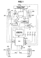
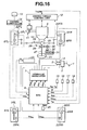
- the lane deviation prevention (LDP) apparatus of the embodiment is exemplified in an adaptive cruise control (ACC) system equipped rear-wheel-drive vehicle employing an automatic transmission 10 and a rear differential.
- ACC adaptive cruise control
- a braking force control system which regulates hydraulic brake pressures of individual wheel-brake cylinders (i.e., front-left, front-right, rear-left, and rear-right wheel-brake cylinders) independently of each other
- a four-channel braking control system such as a four-channel ABS system for anti-skid control or a four-channel traction control system for traction control is utilized.
- a four-channel braking control system such as a four-channel ABS system for anti-skid control or a four-channel traction control system for traction control is utilized.
- reference sign 1 denotes a brake pedal
- reference sign 2 denotes a brake booster
- reference sign 3 denotes a master cylinder (exactly, a tandem master cylinder used for a dual brake system split into two sections, namely front and rear hydraulic brake sections)
- reference sign 4 denotes a brake fluid reservoir.
- a brake fluid pressure risen by master cylinder 3 depending on the amount of depression of brake pedal 1, is supplied to each of a front-left wheel-brake cylinder 6FL for a front-left road wheel 5FL, a front-right wheel-brake cylinder 6FR for a front-right road wheel 5FR, a rear-left wheel-brake cylinder 6RL for a rear-left road wheel 5RL, and a rear-right wheel-brake cylinder 6RR for a rear-right road wheel 5RR.
- Front-left, front-right, rear-left, and rear-right wheel-brake cylinder pressures are regulated independently of each other by means of a brake fluid pressure control circuit (a wheel cylinder pressure control unit) or a hydraulic modulator 7, which is disposed between master cylinder 3 and each of wheel-brake cylinders 6FL, 6FR, 6RL, and 6RR.
- Hydraulic modulator 7 includes hydraulic pressure control actuators (braking force actuators) respectively associated with first-channel (front-left), second-channel (front-right), third-channel (rear-left), and fourth-channel (rear-right) brake circuits, such that front-left, front-right, rear-left, and rear-right wheel-brake cylinder pressures are built up, held, or reduced independently of each other.
- Each of the hydraulic pressure control actuators of hydraulic modulator 7 is comprised of a proportional solenoid valve such as an electromagnetically-controlled solenoid valve that regulates the wheel-brake cylinder pressure to a desired pressure level.
- a proportional solenoid valve such as an electromagnetically-controlled solenoid valve that regulates the wheel-brake cylinder pressure to a desired pressure level.
- Each of the electromagnetically-controlled solenoid valves of hydraulic modulator 7 is responsive to a command signal from a braking/driving force control unit, simply an electronic control unit (ECU) 8, for regulating the wheel-cylinder pressure of each of wheel-brake cylinders 6FL-6RR in response to the command signal from the output interface of ECU 8, regardless of the braking action (brake-pedal depression) manually created by the driver's foot.
- ECU electronice control unit
- the ACC system equipped rear-wheel-drive vehicle of the embodiment of Fig. 1 also includes an electronic driving torque control unit 12 that controls a driving torque transmitted to rear road wheels 5RL and 5RR serving as drive wheels, by controlling an operating condition of an engine 9, a selected transmission ratio of automatic transmission 10, and/or a throttle opening of a throttle valve 11 (correlated to an accelerator opening Acc).
- the operating condition of engine 9 can be controlled by controlling the amount of fuel injected and/or an ignition timing.
- the engine operating condition can be controlled by the throttle opening control.
- Driving torque control unit 12 is designed to individually control the driving torque transmitted to rear road wheels 5RL and 5RR (drive wheels). Additionally, driving torque control unit 12 is responsive to a driving-torque command signal from ECU 8 in a manner so as to control the driving torque depending on the driving-torque command signal value.
- the ACC system equipped rear-wheel-drive vehicle of the embodiment of Fig. 1 also includes a stereocamera with a charge-coupled device (CCD) image sensor, simply, a monocular camera comprised of a charge-coupled device (CCD) camera (a picture image pick-up device) 13 and a camera controller (serving as a lane marking line detector) 14 as an external recognizing sensor (or a host vehicle's position information detector), which functions to detect the current position information of the ACC system equipped vehicle (the host vehicle) within the driving lane (the host vehicle's traffic lane) and whose sensor signal is used for detecting whether or not the host vehicle tends to deviate from the current driving lane.
- CCD charge-coupled device
- a lane marker or lane marking (or a white lane marking line by which two adjacent lanes are divided), such as a white line, is detected and thus the current host vehicle's traffic lane, exactly, the current position information of the host vehicle within the driving lane, is determined based on the white lane marker detected.
- the processor of camera controller 14 calculates and determines or estimates, based on the image data from CCD camera 13 indicative of the picture image, a host vehicle's yaw angle ⁇ with respect to the sense of the current host vehicle's driving lane, a host vehicle's lateral displacement or a host vehicle's lateral deviation X from a central axis (a reference axis) of the current host vehicle's driving lane, and a curvature ⁇ of the current host vehicle's driving lane.
- the host vehicle's yaw angle ⁇ means an angle between the sense of the current host vehicle's driving lane and the host vehicle's x-axis of a vehicle axis system (x, y, z).
- each of detection parameters namely, the host vehicle's yaw angle ⁇ , lateral displacement X, and curvature ⁇ of the host vehicle's driving lane is set to "0".
- camera controller 14 is designed to detect the host vehicle's driving lane information, while utilizing a hypothetical driving lane detection area, which can be initialized and updated to detect a white lane marker, and then computes the host vehicle's driving state indicative data and traveling-path condition indicative data, such as yaw angle ⁇ , lateral displacement X, and curvature ⁇ , based on the detected driving lane.
- a left-hand white lane marker and a right-had white lane marker are detected, and thereafter the host vehicle's driving lane information is estimated or determined, utilizing the detected left and right lane markers.
- a small driving lane detection area called "a window”
- a lane-marker detecting or scanning operation is made within the small driving lane detection area (the window).
- the traveling direction of the host vehicle with respect to the central axis of the driving lane changes, the position of the lane marker on the road image also changes.
- the traveling direction of the host vehicle with respect to the central axis of the driving lane must be estimated.
- the traveling direction of the host vehicle with respect to the central axis of the driving lane is estimated based on a steer angle.
- the previously-noted small driving lane detection area is suitably updated by a new window having a high possibility that the lane marker may be picture-imaged within the new window. After this, in order to highlight the boundary between the lane marker and the road surface of the road image, a specific filtering process is made.
- a certain point on the boundary line highlighted and filter-processed is selected or determined as a lane-marker candidate point.
- a plurality of lane-marker candidate points are determined, and set or plotted on the road image.
- the lane marker can be obtained or detected as the set of lane-marker candidate points continuously linking to each other.
- the method of detecting or estimating the white lane marker while utilizing the small driving lane detection area (the window), partially extracted from the picture image (the road image) captured by the CCD camera, is conventional and forms no part of the present invention.
- One such lane-marker detection method has been disclosed in Japanese Patent Provisional Publication No. 11-296660 .
- Electronic control unit (ECU) 8 generally comprises a microcomputer that includes a central processing unit (CPU) or a microprocessor (MPU), memories (RAM, ROM), and an input/output interface (I/O).
- CPU central processing unit
- MPU microprocessor
- RAM random access memory
- ROM read-only memory
- I/O input/output interface
- the input/output interface (I/O) of ECU 8 receives input information from various engine/vehicle switches and sensors, such as an acceleration sensor (G sensor) 15, a yaw rate sensor 16, a master-cylinder pressure sensor 17, an accelerator opening sensor 18, a steer angle sensor 19, front-left, front-right, rear-left, and rear-right wheel speed sensors 22FL, 22FR, 22RL, and 22RR, and a direction indicator switch 20.
- ECU 8 is electrically connected to driving torque control unit 12.
- Acceleration sensor 15 is provided to detect a longitudinal acceleration Xg and a lateral acceleration Yg, exerted on the host vehicle, and/or to detect a vertical acceleration of a point of the vehicle suspension, moving up and down.
- Yaw rate sensor 16 is provided to detect a yaw rate ⁇ ' (one of the host vehicle's driving states) resulting from a yaw moment acting on the host vehicle.
- Master-cylinder pressure sensor 17 is provided to detect a master-cylinder pressure Pm of master cylinder 3, that is, the amount of depression of brake pedal 1.
- Accelerator opening sensor 18 is provided to detect an accelerator opening Acc (correlated to a throttle opening), which is dependent on a manipulated variable of the driver's accelerator-pedal depression.
- Steer angle sensor 19 is provided to detect steer angle ⁇ of a steering wheel 21.
- Front-left, front-right, rear-left, and rear-right wheel speed sensors 22FL, 22FR, 22RL, and 22RR are provided respectively to detect front-left, front-right, rear-left, and rear-right wheel speeds Vw FL , Vw FR , Vw RL , and Vw RR , which are collectively referred to as "Vwi".
- Direction indicator switch 20 is provided to detect whether a direction indicator is turned on and also to detect the direction indicated by the direction indicator, and to output a direction indicator switch signal WS.
- a radar controller using a radar sensor such as a scanning laser radar sensor serving as an object detector, may be provided to more precisely capture, recognize, sense, or detect a preceding vehicle (or a relevant target vehicle), or a frontally located object, or a running vehicle on the adjacent lane.
- these input informational data are used for collision avoidance control as well as lane deviation prevention (LDP) control, containing both of yaw moment control and vehicle deceleration control (described later).
- LDP lane deviation prevention
- a change in the vehicle driving state indicative data to the left is indicated as a positive value, while a change in the vehicle driving state indicative data to the right is indicated as a negative value. More concretely, during a left turn, yaw rate ⁇ ', lateral acceleration Yg, steer angle ⁇ , and yaw angle ⁇ are all indicated as positive values.
- lateral displacement X is indicated as a positive value when the host vehicle is deviated from the central axis of the current driving lane to the left. Conversely when the host vehicle is deviated from the central axis of the current driving lane to the right, lateral displacement X is indicated as a negative value.
- the positive signal value of direction indicator switch signal WS from direction indicator switch 20 means a left turn (counterclockwise rotation of direction indicator switch 20), whereas the negative signal value of direction indicator switch signal WS means a right turn (clockwise rotation of direction indicator switch 20).
- ECU 8 is also connected to a warning system 23 having a warning buzzer and/or a warning light, which comes on in response to an alarm signal AL from ECU 8, so that a visual and/or audible warning is signaled to the driver.
- the central processing unit CPU
- the central processing unit allows the access by the I/O interface of input informational data signals from the previously-discussed engine/vehicle switches and sensors and camera controller 14 and driving torque control unit 12, and is responsible for carrying various control programs stored in the memories and capable of performing necessary arithmetic and logic operations (described later in reference to Figs. 2 , 15 or 17 ).
- Computational results or arithmetic calculation results are relayed via the output interface circuitry to the output stages, for example, the solenoids of hydraulic modulator 7 and the warning buzzer/warning light of warning system 23.
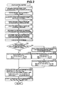
- the LDP control routine executed by ECU 8 incorporated in the automotive LDP apparatus of the embodiment shown in Fig. 1 is hereunder described in detail in reference to the flow chart shown in Fig. 2 .
- the LDP control routine of Fig. 2 is executed as time-triggered interrupt routines to be triggered every predetermined sampling time intervals ⁇ T such as 20 milliseconds.
- step S1 input informational data from the previously-noted engine/vehicle switches and sensors, and driving-torque controller 12 and camera controller 14 are read.
- engine/vehicle switch/sensor signal data such as the host vehicle's longitudinal acceleration Xg, lateral acceleration Yg, yaw rate ⁇ ', wheel speeds Vwi (Vw FL , Vw FR , Vw RL , Vw RR ), accelerator opening Acc, master-cylinder pressure Pm, steer angle ⁇ , and direction indicator switch signal WS, and signal data from driving-torque control unit 12 such as driving torque Tw, and signal data from camera controller 14 such as the host vehicle's yaw angle ⁇ with respect to the direction of the current host vehicle's driving lane, lateral displacement X from the central axis of the current host vehicle's driving lane, curvature ⁇ of the current driving lane, and the recognition signal regarding whether or not the white lane marker is detected by camera controller 14.
- driving-torque control unit 12 such
- the host vehicle's yaw angle ⁇ may be calculated by integrating yaw rate ⁇ ' detected by yaw rate sensor 16. Additionally, at step S1, a check is made to determine whether or not the recognition signal from camera controller 14 indicates a state where the white lane marking line in front of the host vehicle is sufficiently satisfactorily detected. When the recognition signal from camera controller 14 indicates a state where the white lane marking line in front of the host vehicle is detected, a so-called recognition flag Fcr is set to "1". Conversely when the recognition signal from camera controller 14 indicates a state where the white lane marking line in front of the host vehicle is not detected, recognition flag Fcr is reset to "0".
- detection parameters namely, the host vehicle's yaw angle ⁇ , lateral displacement X, and curvature ⁇ of the host vehicle's driving lane are stored as the latest up-to-date informational data in predetermined memory addresses of the RAM of ECU 8.
- detection parameters namely, the host vehicle's yaw angle ⁇ , lateral displacement X, and curvature ⁇ of the host vehicle's driving lane are set to "0".
- a host vehicle's speed V is calculated.
- a pseudo vehicle speed used for skid control may be used as host vehicle speed V.
- a lateral-displacement estimate XS in other words, an estimate of a future lateral deviation or an estimate of a future lateral displacement, is estimated or arithmetically calculated.
- Tt denotes a headway time between the host vehicle and the preceding vehicle both driving in the same sense and in the same lane
- the product (Tt ⁇ V) of the headway time Tt and the host vehicle's speed V means a distance between the current position of the host vehicle and the forward point-of-fixation. That is, an estimate of lateral deviation from the central axis of the current host vehicle's driving lane, which may occur after the headway time Tt, is regarded as a future lateral-displacement estimate XS.
- the processor of ECU 8 determines that there is an increased tendency for the host vehicle to deviate from the current driving lane.
- a check for the lane-marker detecting state or the lane-marker non-detecting state is made based on the state of recognition flag Fcr, calculated at the current execution cycle.
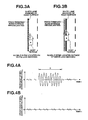
- a detection for predetermined road-surface irregularities often called “rumble strip", which are artificially formed on the white lane marking line or the white lane marker (see Fig. 3A ) or equidistantly repeatedly formed outside of and close to the white lane marker (see Fig. 3B ), is made.
- rumble strip a detection for predetermined road-surface irregularities, often called "rumble strip" which are artificially formed on the white lane marking line or the white lane marker (see Fig. 3A ) or equidistantly repeatedly formed outside of and close to the white lane marker.
- a check is made to determine whether or not either one of road wheels of the host vehicle is traveling on predetermined road-surface irregularities (the rumble strip).
- such predetermined artificial road-surface irregularities are generally equidistantly repeatedly formed on the white lane marker or equidistantly repeatedly formed outside of and close to the white lane marker.
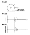
- FIGS. 4A and 4B respectively show fluctuations in front-left wheel acceleration dVw FL and fluctuations in front-right wheel acceleration dVw FR under a specific condition where the host vehicle begins to deviate from the current driving lane and the front-left road wheel begins to travel on the predetermined artificial road-surface irregularities (the rumble strip).
- the axis of ordinate indicates wheel acceleration dVwi
- the axis of abscissa indicates the elapsed time t.
- the degree of wheel speed fluctuations or the degree of wheel acceleration fluctuations, monitored by each wheel speed sensor 22i can be properly varied or tuned depending on the pitch of the predetermined artificial road-surface irregularities (the rumble strip), the resolving power of the wheel speed sensor (the number of pulses generated per one revolution of the road wheel, in other words, the number of teeth of a toothed disc in a pulse-generator-type wheel speed sensor), tire and suspension characteristics, and the like. For instance, suppose that the pitch of the predetermined artificial road-surface irregularities (the rumble strip) or the distance between two adjacent ridged portions of the predetermined artificial road-surface irregularities is adequately large or wide, and also the resolving power of wheel speed sensor 22i is adequately high.
- the predetermined artificial road-surface irregularities are comprised of ridged portions equidistantly repeatedly formed on the road surface.
- the predetermined artificial road-surface irregularities may be comprised of recessed portions equidistantly repeatedly formed on the road surface.
- step S4 the presence of wheel speed fluctuations for only one of steered road wheels, namely front-left and front-right road wheels 5FL and 5FR, is hereinafter explained, because the arithmetic operations of step S4 are the same in the host vehicle's lane deviations to the left or to the right.
- the following specific checks are made.
- a wheel acceleration/deceleration (simply, a wheel acceleration) dVwi is arithmetically calculated based on the latest up-to-date information concerning wheel speed Vwi read through step S1 from the following expression (2).
- dVwi Kg ⁇ Vwi k - 1 - Vwi k / ⁇ T
- Vwi (k) denotes the current value of wheel speed Vwi
- Vwi (k-1) denotes the previous value of wheel speed Vwi, calculated one cycle before (i.e., 20 milliseconds before)
- Kg denotes a unit conversion factor
- ⁇ T denotes a predetermined sampling time interval such as 20 milliseconds.
- step S4 a check is made to determine whether the calculated wheel acceleration dVwi (k) becomes greater than a decision threshold value S limt .
- a further check is made to determine whether a predetermined time interval has expired from a time when wheel speed Vwi has been fluctuating one cycle before and thus the condition dVwi (k-1) >S limt has been satisfied.
- a count value Tsi of a count-down timer is compared to a predetermined threshold value TsL.
- the count value Tsi of the count-down timer is less than or equal to predetermined threshold value TsL, that is, 0 ⁇ Tsi ⁇ TsL
- decision threshold value S limt is arithmetically calculated or map-retrieved as a variable based on host vehicle speed V, from the predetermined host vehicle speed V versus decision threshold value S limt characteristic map of Fig. 6 showing how a decision threshold value S limt has to be varied relative to a host vehicle speed V.
- decision threshold value S limt is fixed to a predetermined maximum threshold value S limtH .
- decision threshold value S limt gradually reduces to a predetermined minimum threshold value S limtL , as the host vehicle speed V increases.
- decision threshold value S limt is fixed to predetermined minimum threshold value S limtL .
- initial set value Tso of the count-down timer is arithmetically calculated or map-retrieved as a variable based on host vehicle speed V, from the predetermined host vehicle speed V versus initial set value Tso characteristic map of Fig.
- initial set value Tso gradually reduces to a predetermined minimum initial set value T SOL , as the host vehicle speed V increases.
- initial set value Tso is fixed to predetermined minimum initial set value T SOL .
- decision threshold value S limt is fixed to predetermined maximum threshold value S limtH in the low vehicle speed range (0 ⁇ V ⁇ V 1 ), and fixed to predetermined minimum threshold value S limtL in the excessively high vehicle speed range (V 2 ⁇ V), and gradually reduces to predetermined minimum threshold value S limtL in a linear fashion as the host vehicle speed V increases in the middle ) vehicle speed range (V 1 ⁇ V ⁇ V 2 ).
- count-down-timer initial set value Tso is fixed to predetermined maximum initial set value T SOH in the low vehicle speed range (0 ⁇ V ⁇ V 3 ), and fixed to predetermined minimum initial set value T SOL in the excessively high vehicle speed range (V 4 ⁇ V), and gradually reduces to predetermined minimum initial set value T SOL in a linear fashion as the host vehicle speed V increases in the middle vehicle speed range (V 3 ⁇ V ⁇ V 4 ).
- the count value Tsi of the count-down timer is greater than predetermined threshold value TsL, the count value Tsi of the count-down timer is decremented by a predetermined value, while a count value Trsi of a road-surface irregularities estimation timer is incremented by the predetermined value (see Figs. 8B and 8D ). If the count value Tsi of the count-down timer is less than or equal to "0", road-surface estimation starting flag Frsi is reset to "0" and additionally the count value Trsi of the road-surface irregularities estimation timer is reset to "0".
- a road-surface irregularities decision flag Foti is set to "1" (see the time period C of each of the time charts of Figs. 8D and 8E ).
- road-surface irregularities decision flag Foti is set to "1" (see the time period C of each of the time charts of Figs. 8D and 8E ). Setting of road-surface irregularities decision flag Foti to "1" means that the road wheel is now traveling on the predetermined irregularities (corresponding to the ridge portions or recessed portions) equidistantly repeatedly formed on the road surface.
- road-surface irregularities decision flag Foti may be undesirably set to "1".
- the system erroneously determines that the host vehicle is traveling on the road-surface irregularities, in particular during the host vehicle's driving on bad roads such as rugged terrain.
- a check for the host vehicle traveling on the predetermined road-surface irregularities can be made accurately, while adequately taking account of the periodical fluctuation in wheel acceleration dVwi, that is, the cyclic fluctuation in wheel speed Vwi.
- the LDP control system of the embodiment utilizes the periodical fluctuation in wheel acceleration dVwi (or the periodical fluctuation in wheel speed Vwi).
- the processor of ECU 8 may be constructed to detect the unpaved driving-lane edge having uneven portions or the unpaved road edge having uneven portions.
- the processor of ECU 8 may determine that either one of the left and right road wheels of the host vehicle is traveling on the uneven portions of the unpaved driving-lane edge or the unpaved road edge, when wheel speed Vwi continuously oscillates for a time period greater than or equal to a preset time period. It is possible to detect the uneven portions of the unpaved driving-lane edge (or the unpaved road edge) as well as the predetermined artificial road-surface irregularities. Subsequently to step S4, step S5 occurs.
- a check is made to determine, based on road-surface irregularities decision flag Fot FL associated with front-left road wheel 5FL and road-surface irregularities decision flag Fot FR associated with front-right road wheel 5FR, whether the host vehicle is traveling on either one of the leftmost and rightmost edges of the current driving lane.
- road-surface irregularities decision flag Fot FL associated with front-left road wheel 5FL is set to "1"
- road-surface irregularities decision flag Fot FR associated with front-right road wheel 5FR is reset to "0”
- the processor of ECU 8 determines that the host vehicle is now traveling on the left-hand edge of its driving lane, and thus a road-edge decision flag (or a driving-lane edge decision flag) Fdw is set to "+1".
- road-surface irregularities decision flag Fot FL associated with front-left road wheel 5FL is reset to "0" and road-surface irregularities decision flag Fot FR associated with front-right road wheel 5FR is set to "1"
- the processor of ECU 8 determines that the host vehicle is now traveling on the right-hand edge of its driving lane, and thus a road-edge decision flag (or a driving-lane edge decision flag) Fdw is set to "-1".
- road-surface irregularities decision flag Fot FL for front-left road wheel 5FL and road-surface irregularities decision flag Fot FR for front-right road wheel 5FR are both set to "1", or when flags Fot FL and Fot FR are both reset to "0", road-edge decision flag Fdw is reset to "0".
- the system determines that the host vehicle is running on the road-surface irregularities.
- a check is made to determine, based on direction indicator switch signal WS from direction indicator switch 20 and steer angle ⁇ detected by steer angle sensor 19, whether a driver's intention for lane changing is present or absent. Concretely, at step S6, a check is made to determine whether direction indicator switch 20 is turned ON. When direction indicator switch 20 is turned ON, a further check is made to determine whether the sign of direction indicator switch signal WS is identical to the sign of lateral-displacement estimate XS calculated through step S3 or the sign of lateral displacement X (read through step S1) from the central axis of the current host vehicle's driving lane.
- the processor of ECU 8 determines that the host vehicle is conditioned in the lane changing state, and thus a lane-changing indicative flag F LC is set to "1". Conversely when the sign of direction indicator switch signal WS and the sign of lateral-displacement estimate XS (or the sign of lateral displacement X) are not identical to each other, the processor of ECU 8 determines that the host vehicle is not conditioned in the lane changing state but there is an increased tendency of the host vehicle's lane deviation, and thus lane-changing indicative flag F LC is reset to "0".
- lane-changing indicative flag F LC is held at "1" for a predetermined time interval, such as four seconds, from the time when lane-changing indicative flag F LC has been set to "1" by turning the direction indicator switch 20 ON. This is because there is a possibility that direction indicator switch 20 is manually turned OFF during lane-changing and thus the LDP control may be engaged undesirably. More concretely, a check is made to determine whether direction indicator switch 20 has been switched from the turned-ON state to the turned-OFF state.
- ECU 8 determines that the current point of time corresponds to the time just after lane-changing operation, and thus a further check is made to determine whether the predetermined time interval, for example four seconds, measured or counted from the time when switching from the turned-ON state of direction indicator switch 20 to turned-OFF state has occurred, has expired.
- the predetermined time interval e.g., 4 seconds
- lane-changing indicative flag F LC is reset to "0".
- a still further check for the presence or absence of the driver's intention for lane changing is made based on steer angle ⁇ and a variation ⁇ in steer angle ⁇ .
- a check is made to determine whether steer angle ⁇ is greater than or equal to a predetermined steer angle ⁇ s and additionally a variation ⁇ in steer angle ⁇ is greater than or equal to a predetermined change ⁇ s .
- ECU 8 determines that a driver's intention for lane changing is present, and thus lane-changing indicative flag F LC is set to "1".
- step S6 the presence or absence of the driver's intention for lane changing is determined based on both of steer angle ⁇ and its change ⁇ . In lieu thereof, the presence or absence of the driver's intention for lane changing may be determined based on the magnitude of steering torque acting on the steering wheel.
- a check is made to determine, based on the absolute value
- a check is made to determine whether lane-changing indicative flag F LC is reset to "0" and additionally the absolute value
- Predetermined alarm criterion X W is obtained by subtracting a predetermined margin X m (a predetermined constant) from a predetermined lateral-displacement criterion X C (see the following expression (3)).
- lateral-displacement criterion X C means a preset criterion threshold value of lateral displacement of the host vehicle from the central axis of the current host vehicle's driving lane
- predetermined margin X m corresponds to a margin from a time when warning system 23 has been switched to an operative state to a time when the LDP function has been engaged or enabled.
- lateral-displacement criterion X C is set to 0.8 meter, since a width of a traffic lane of an express-highway in Japan is 3.35 meters.
- ECU 8 determines that the host vehicle is in a lane-deviation state where there is an increased tendency for the host vehicle to deviate from the current host vehicle's driving lane, and thus the output interface of ECU 8 generates alarm signal AL to warning system 23.
- F LC 1 or
- ⁇ X W ECU 8 determines that the host vehicle is out of the lane-deviation state, and thus another check is made to determine whether or not warning system 23 is in operation.
- warning system 23 During operation of warning system 23, another check is made to determine whether the absolute value
- Predetermined hysteresis X h is provided to avoid undesirable hunting for warning system 23.
- warning system 23 is deactivated by stopping the output of alarm signal AL to warning system 23.
- the warning operation of warning system 23 is continually executed.
- the visual and/or audible warning (the output of alarm signal AL to warning system 23) is dependent upon only the amount of lateral displacement (exactly, the absolute value
- lateral-displacement criterion X C is fixed to a predetermined constant value. Actually, a lane width L of each of driving lanes is not fixed constant.
- lateral-displacement criterion X C may be a variable, which is determined depending on lane width L of each of driving lanes.
- the lane width L itself can be obtained by image-processing the picture image data from CCD camera 13 or by extracting input information regarding the lane width of the current driving lane as map data, utilizing a navigation system.
- lateral-displacement criterion X C which is a variable, can be calculated from the following expression.
- X C min L / 2 - L 0 / 2 0.8 where L 0 denotes a host vehicle's width and L denotes a lane width.
- lateral-displacement criterion X C is obtained as a lower one of the value (L/2-L 0 /2) and 0.8 (unit: meter) by way of a so-called select-LOW process.
- a distance data (L/2-XS), which is obtained and received by way of mutual communication between the host vehicle and the on-road network (or the on-road sensor or the on-road lane marker) contained in the infrastructure, may be used as input information regarding an estimate of lateral-displacement criterion X C . Subsequently to step S7, step S8 occurs.
- the processor of ECU 8 makes a lane-deviation decision based on the picture image data concerning the white lane marker in front of the host vehicle, in other words, a comparison result between lateral-displacement estimate XS and lateral-displacement criterion X C , so as to determine whether there is a possibility or an increased tendency of lane deviation of the host vehicle from the current driving lane.
- a check is made to determine whether lateral-displacement estimate XS is greater than or equal to lateral-displacement criterion X C (a positive lane-deviation criterion).
- lane-deviation decision flag F LD is set to "+1".
- a lane-deviation decision flag F LD is set to "+1".
- the processor of ECU 8 determines that there is a less possibility of the host vehicle's lane deviation from the current driving lane to the right or to the left, and thus lane-deviation decision flag F LD is reset to "0".
- a compensation for lane-deviation decision flag F LD and road-edge decision flag Fdw is made based on lane-changing indicative flag F LC .
- a further check is made to determine whether lane-changing indicative flag F LC is set to "1".
- lane-deviation decision flag F LD is also forcibly reset to "0".
- step S9 occurs.
- Fdw road-edge decision flag
- the routine proceeds from step S9 to step S10.
- the routine proceeds fro step S9 to step S11.
- a desired yaw moment Ms needed to avoid the host vehicle's lane-deviation tendency by execution of LDP control achieved by way of only the yaw moment control, is arithmetically calculated or derived, depending on the state of lane-deviation decision flag F LD , as follows.
- a check is made to determine whether lane-deviation decision flag F LD is kept at the set state (F LD +1 or -1), in other words, F LD ⁇ 0.
- F LD ⁇ 0 that is, when the processor of ECU 8 determines, based on the difference (XS-X C ) between lateral-displacement estimate XS and predetermined lateral-displacement criterion X C , that there is an increased tendency for the host vehicle to deviate from the driving lane, desired yaw moment Ms is arithmetically calculated from the following expression (4).
- K1 denotes a proportional gain that is determined by specifications of the host vehicle
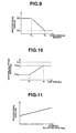
- K2 denotes a proportional gain that is determined by host vehicle speed V and retrieved based on the latest up-to-date informational data of host vehicle speed V from the predetermined host vehicle speed V versus proportional gain K2 characteristic map of Fig. 9 showing how a proportional gain K2 has to be varied relative to a host vehicle speed V.
- K1 denotes a proportional gain that is determined by specifications of the host vehicle
- K2 denotes a proportional gain that is determined by host vehicle speed V and retrieved based on the latest up-to-date informational data of host vehicle speed V from the predetermined host vehicle speed V versus proportional gain K2 characteristic map of Fig. 9 showing how a proportional gain K2 has to be varied relative to a host vehicle speed V.
- proportional gain K2 in a low vehicle speed range (0 ⁇ V ⁇ V 5 ) from 0 to a predetermined vehicle speed value V 5 , proportional gain K2 is fixed to a predetermined maximum gain K2 H .
- proportional gain K2 In a middle vehicle speed range (V 5 ⁇ V ⁇ V 6 ) from predetermined low vehicle speed V 5 to a predetermined high vehicle speed V 6 (higher than V 5 ), proportional gain K2 gradually reduces to a predetermined minimum gain K2 L , as the host vehicle speed V increases.
- proportional gain K2 In an excessively high vehicle speed range (V 6 ⁇ V) above predetermined high vehicle speed V 6 , proportional gain K2 is fixed to predetermined minimum gain K2 L .
- step S9 the routine flows from step S9 to step S11.
- control allotment between yaw moment control and vehicle deceleration control is calculated and determined based on the host vehicle's yaw angle ⁇ with respect to the sense of the current host vehicle's driving lane.
- control allotted rate Rxg is computed or map-retrieved from the predetermined yaw angle ⁇ versus control allotted rate Rxg characteristic map shown in Fig. 10 .
- control allotted rate Rxg is set to a positive value less than +1.0, that is, 0 ⁇ Rxg ⁇ +1.0.
- control allotted rate Rxg indicates control allotted rate Rxg
- the axis of abscissa indicates the host vehicle's yaw angle ⁇ .
- control allotted rate Rxg is fixed to a predetermined minimum rate Rxg 1 .
- control allotted rate Rxg In a middle yaw angle range ( ⁇ 1 ⁇ 2 ) from predetermined small yaw angle ⁇ 1 to a predetermined large yaw angle ⁇ 2 (larger than ⁇ 1 ), control allotted rate Rxg gradually increases to a predetermined maximum rate Rxg2, as the yaw angle ⁇ increases. In an excessively large yaw angle range ( ⁇ 2 ⁇ ) above predetermined large yaw angle ⁇ 2 , control allotted rate Rxg is fixed to predetermined maximum rate Rxg2. As discussed above, in the shown embodiment, control allotted rate Rxg is determined based on the host vehicle's yaw angle ⁇ .
- control allotted rate Rxg may be determined based on at least one of host vehicle speed V, curvature ⁇ of the host vehicle's driving lane, yaw rate ⁇ ', lateral acceleration Yg, and the other host vehicle's driving state indicative data and traveling-path condition indicative data.
- desired deceleration rate Xgs to be generated by vehicle deceleration control is determined depending on the state of lane-deviation decision flag F LD .
- desired deceleration rate Xgs is arithmetically calculated based on the difference (XS-X C ) between lateral-displacement estimate XS and predetermined lateral-displacement criterion X C from the following expression (5).
- Kxgs - Kxg ⁇ XS - X C
- Kxg denotes a proportional gain that is determined by control allotted rate Rxg and retrieved based on the latest up-to-date informational data of control allotted rate Rxg from the predetermined control allotted rate Rxg versus proportional gain Kxg characteristic map of Fig. 11 showing how a proportional gain Kxg has to be varied relative to a control allotted rate Rxg.
- proportional gain Kxg is set as a monotone function that proportional gain Kxg increases in a linear fashion, as control allotted rate Rxg increases.
- desired yaw moment Ms to be exerted on the host vehicle by way of yaw moment control executed in parallel with vehicle deceleration control, is arithmetically calculated, depending on the state of lane-deviation decision flag F LD .
- F LD ⁇ 0
- desired yaw moment Ms is arithmetically calculated from the following expression (6).
- K1 and K2 denote the proportional gains previously described in reference to the expression (4)
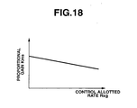
- Km denotes a proportional gain that is determined or retrieved based on the latest up-to-date informational data of control allotted rate Rxg (set through step S11) from the predetermined control allotted rate Rxg versus proportional gain Km characteristic map of Fig. 12 showing how a proportional gain Km has to be varied relative to a control allotted rate Rxg.
- Km denotes a proportional gain that is determined or retrieved based on the latest up-to-date informational data of control allotted rate Rxg (set through step S11) from the predetermined control allotted rate Rxg versus proportional gain Km characteristic map of Fig. 12 showing how a proportional gain Km has to be varied relative to a control allotted rate Rxg.
- proportional gain Km is set as a monotone function that proportional gain Km decreases in a linear fashion, as control allotted rate Rxg increases.
- F LD 0
- desired braking forces for the individual road wheels that is, front-left, front-right, rear-left, and rear-right desired wheel-brake cylinder pressures Ps FL , Ps FR , Ps RL and Ps RR , which are collectively referred to as "Psi" are calculated based on master cylinder pressure Pm read through step S1, desired yaw moment Ms determined through steps S10 or S13, and desired deceleration rate Xgs determined through step S12.
- Psi desired braking forces for the individual road wheels
- an equivalent controlled master-cylinder pressure Pmcnt is arithmetically calculated based on desired deceleration rate Xgs from the following expression (7).
- Pmcnt Kmxg ⁇ Xgs
- Kmxg denotes a conversion coefficient that is determined by specifications of the host vehicle.
- a so-called select-HIGH processed master-cylinder pressure simply, a selected master-cylinder pressure Pmsel is calculated from the following expression.
- Pmcnt Kmxg ⁇ Xgs
- Pmcnt denotes the equivalent controlled master-cylinder pressure calculated based on desired deceleration rate Xgs
- Pm denotes the master-cylinder pressure detected by master-cylinder pressure sensor 17.
- selected master-cylinder pressure Pmsel is obtained as a higher one of the equivalent controlled master-cylinder pressure Pmcnt based on desired deceleration rate Xgs and master-cylinder pressure Pm detected.
- desired wheel-brake cylinder pressures Psi are calculated based on the state of lane-deviation decision flag F LD and the state of road-edge decision flag Fdw.
- front-left and front-right desired wheel-brake cylinder pressures Ps FL and Ps FR for front wheel-brake cylinders 6FL and 6FR are set to selected master-cylinder pressure Pmsel (see the following expressions), whereas rear-left and rear-right desired wheel-brake cylinder pressures Ps RL and Ps RR for rear wheel-brake cylinders 6RL and 6RR are set to a rear-wheel brake pressure or a rear-wheel master-cylinder pressure PmR (see the following expressions), which is calculated and usually reduced from master-cylinder pressure Pm, while taking into account wheel-brake
- each of desired front and rear wheel-brake cylinder pressures Ps FL , Ps FR , Ps RL and Ps RR is calculated based on the magnitude of desired yaw moment Ms.
- the processor of ECU 8 determines each of desired wheel-brake cylinder pressures Ps FL through Ps RR in such a manner as to provide only the differential pressure between rear road wheels 5RL and 5RR. In other words, the differential pressure between front road wheels 5FL and 5FR is set to "0".
- the front desired wheel-brake cylinder pressure difference ⁇ Ps F between front-left and front-right desired wheel-brake cylinder pressures Ps FL and Ps FR , and the rear desired wheel-brake cylinder pressure difference ⁇ Ps R between rear-left and rear-right desired wheel-brake cylinder pressures Ps RL and Ps RR are determined from the following expression (8).
- Kb R denotes a predetermined conversion coefficient used to convert a rear-wheel braking force into a rear wheel-brake cylinder pressure
- T denotes a rear-wheel tread (or a rear-wheel track).
- the rear-wheel track T is set to be identical to a front-wheel track.
- the processor of ECU 8 determines each of desired wheel-brake cylinder pressures Ps FL through Ps RR in such a manner as to provide both of the differential pressure between front road wheels 5FL and 5FR and the differential pressure between rear road wheels 5RL and 5RR.
- front and rear desired wheel-brake cylinder pressure differences ⁇ Ps F and ⁇ Ps R are represented by the following expressions (9) and (10).
- Kb F denotes a predetermined conversion coefficient used to convert a front-wheel braking force into a front wheel-brake cylinder pressure
- Kb R denotes a predetermined conversion coefficient used to convert a rear-wheel braking force into a rear wheel-brake cylinder pressure
- T of the expression (9) and T of the expression (10) denote front and rear wheel treads being the same in front and rear wheels
- Ms0 denotes the predetermined desired yaw-moment threshold value.
- lane-deviation decision flag F LD is set to "+1"
- front-left desired wheel-brake cylinder pressure Ps FL is set to selected master-cylinder pressure Pmsel
- front-right desired wheel-brake cylinder pressure Ps FR is set to the sum (Pmsel+ ⁇ Ps F ) of selected master-cylinder pressure Pmsel and front desired wheel-brake cylinder pressure difference ⁇ Ps F
- rear-left desired wheel-brake cylinder pressure Ps RL is set to rear-wheel master-cylinder pressure PmR
- rear-right desired wheel-brake cylinder pressure Ps RR is set to the sum (PmR+ ⁇ Ps R ) of rear-wheel master-cylinder pressure PmR and rear desired wheel-brake
- front-left desired wheel-brake cylinder pressure Ps FL is set to the sum (Pm+ ⁇ Ps F ) of selected master-cylinder pressure Pmsel and front desired wheel-brake cylinder pressure difference ⁇ Ps F
- front-right desired wheel-brake cylinder pressure Ps FR is set to selected master-cylinder pressure Pmsel
- rear-left * desired wheel-brake cylinder pressure Ps RL is set to the sum (PmR+ ⁇ Ps R ) of rear-wheel master-cylinder pressure PmR and rear desired wheel-brake cylinder pressure difference ⁇ Ps R
- rear-right desired wheel-brake cylinder pressure Ps RR is set to
- a desired driving torque TrqDS is arithmetically calculated as detailed hereunder, under a particular condition where there is a possibility that the host vehicle tends to deviate from the current driving lane and the LDP control is operative (F LD ⁇ 0).
- TrqDs f Acc - g Ps
- f(Acc) is a function of accelerator opening Acc read through step S1 and the function f(Acc) is provided to calculate a desired driving torque that is determined based on the accelerator opening Acc and required to accelerate the host vehicle
- TrqDS f Acc
- a higher priority is put on the controlled variable of LDP control rather than the manipulated variable of the accelerator pedal by the driver.
- a higher priority may be put on the manipulated variable of the accelerator pedal by the driver rather than the controlled variable of LDP control, such that the absolute value
- command signals corresponding to front-left, front-right, rear-left, and rear-right desired wheel-brake cylinder pressures Ps FL , Ps FR , Ps RL , and Ps RR , calculated through step S14, are output from the input interface of ECU 8 to hydraulic modulator 7, and at the same time a command signal corresponding to desired driving torque TrqDS, calculated through the same step S14, is output from the output interface of ECU 8 to driving torque control unit 12.
- one cycle of the time-triggered interrupt routine terminates and the predetermined main program is returned.
- the automotive LDP apparatus of the embodiment executing the LDP control routine shown in Fig. 2 operates as follows.
- the host vehicle's dynamic behavior can be determined by the driver's manual steering operation, brake-pedal depression, and accelerator-pedal depression.
- step S1 of Fig. 2 input informational data from the previously-noted engine/vehicle switches and sensors, and driving-torque controller 12 and camera controller 14 are read (see step S1 of Fig. 2 ).
- Recognition flag Fcr is set to "1", since the white lane marker in front of the host vehicle is satisfactorily detected and captured by CCD camera 13.
- X W predetermined alarm criterion X W
- warning system 23 comes into operation so that a visual and/or audible warning is signaled to the driver. The driver is informed of the increased lane-deviation tendency of the host vehicle.
- lateral-displacement estimate XS is further increasing after the condition defined by XS>X W has been satisfied. At this time, lateral-displacement estimate XS reaches predetermined lateral-displacement criterion X C . As soon as lateral-displacement estimate XS exceeds predetermined lateral-displacement criterion X C and then the condition defined by
- ⁇ Xc is satisfied, lane-deviation decision flag F LD is set (F LD 1). At the point of time, suppose that the host vehicle comes nearer to the left white lane marker of the driving lane, but still travels within the left white lane marker. Therefore, the host vehicle does not yet on the road-surface irregularities (the rumble strip).
- step S10 the LDP control is executed by way of only the yaw moment control.
- a suitable yaw moment produced by LDP control based on only the yaw moment control without vehicle deceleration control, is exerted on the host vehicle so as to effectively suppress the host vehicle's lane deviation from the driving lane to the left and to rapidly reduce the host vehicle's lateral displacement from the center axis of the current driving lane.
- ECU 8 determines, through step S4 of the LDP control routine of Fig. 2 , that the host vehicle is now traveling on the road-surface irregularities.
- step S5 ECU 8 determines that the host vehicle is now traveling on the left-hand edge of the current driving lane, and thus road-edge decision flag Fdw is set to "+1".
- control allotted rate Rxg is determined based on the host vehicle's yaw angle ⁇ .
- desired wheel-brake cylinder pressures Psi are calculated.
- the braking torque and driving torque of each road wheel are controlled suitably to avoid the host vehicle's lane deviation. As a consequence, as clearly shown in Fig.
- the clockwise yawing moment corresponding to desired yaw moment Ms is exerted on the host vehicle according to the yaw moment control so as to effectively suppress the host vehicle's lane deviation to the left, and at the same time the braking torque corresponding to desired deceleration rate Xgs is applied to the host vehicle according to the vehicle deceleration control.
- two control actions namely yaw moment control producing desired yaw moment Ms and vehicle deceleration control producing desired deceleration rate Xgs, can be performed simultaneously.
- lane deviation prevention (LDP) control is achieved by way of only the yaw moment control producing desired yaw moment Ms to suppress or reduce the host vehicle's lane-deviation tendency.
- LDP lane deviation prevention
- the host vehicle may come into collision with a frontally-located object such as another vehicle or the host vehicle may roll.
- the LDP apparatus of the embodiment can provide an active safety system (a combined active safety system of the yaw moment control system and the vehicle deceleration control system) as well as a passive warning system.
- control allotted rate Rxg is determined or map-retrieved based on the host vehicle's yaw angle ⁇ (see Fig. 10 ). For instance, when the host vehicle's yaw angle ⁇ is comparatively large, that is, in case of the increased lane-deviation tendency, in other words, when there is a high possibility of a collision or a roll, control allotted rate Rxg can be set to a high rate. Owing to control allotted rate Rxg set to high, proportional gain Kxg needed for calculation of desired deceleration rate Xgs can be set to a high value (see Fig.
- control allotted rate of vehicle deceleration control to yaw moment control can be increased, and thus it is possible to effectively reduce or eliminate undesirable shock and impact of a collision or a roll.
- control allotted rate Rxg can be set to a low rate.
- proportional gain Kxg needed for calculation of desired deceleration rate Xgs can be set to a low value (see Fig. 11 ), whereas proportional gain Km needed for calculation of desired yaw moment Ms can be set to a high value (see Fig. 12 ).
- the control allotted rate of vehicle deceleration control to yaw moment control is decreased, in other words, the control allotted rate of yaw moment control to vehicle deceleration control is increased.
- a higher priority is put on yaw moment control rather than vehicle deceleration control, to preferentially rapidly reduce or suppress the host vehicle's lane-deviation tendency by way of the highly control-allotted yaw moment .control.
- a higher priority can be put on a preferable one of two control actions, namely yaw moment control and vehicle deceleration control, depending on the host vehicle's driving state including at least yaw angle ⁇ .
- lane-deviation decision flag F LD and road-edge decision flag Fdw can be forcibly reset to "0".
- the LDP control function is not engaged, in other words, yaw moment control and vehicle deceleration control are both inhibited.
- the LDP apparatus of the embodiment can forcibly, actively execute vehicle deceleration control and yaw moment control both properly control-allotted, when there is a host vehicle's lane-deviation tendency, thus effectively actively suppressing the host vehicle's lane-deviation tendency and effectively reducing or eliminating undesirable shock and impact of a collision (or a vehicle roll) after the host vehicle has deviated from its driving lane.
- the LDP apparatus of the embodiment is able to check for the host vehicle traveling on the road-surface irregularities, such as rumble strips, artificially formed on the white lane marker or equidistantly repeatedly formed outside of and close to the white lane marker.
- the LDP apparatus of the embodiment can perform LDP control, while avoiding undesirable interference between the host vehicle's decelerating action based on LDP control and the host vehicle's decelerating action based on the driver's brake-pedal depression and also avoiding undesirable interference between the host vehicle's accelerating action based on LDP control and the host vehicle's accelerating action based on the driver's accelerator-pedal depression (see step S14).
- LDP lane deviation prevention
- LDA lane deviation avoidance
- the LDP apparatus of the embodiment is designed to detect, based on the wheel-speed indicative sensor signal from each of wheel-speed sensors 22i, whether or not the host vehicle is traveling on the road-surface irregularities.
- wheel speed sensors are usually installed for detecting or estimating deceleration slip or acceleration slip or vehicle speed.
- the LDP apparatus of the embodiment can utilize sensor signals from the existing wheel speed sensors. This eliminates the necessity of additional sensors for detection of the road-surface irregularities, thus downsizing the LDP control system and also reducing total manufacturing costs of the LDP apparatus.
- the LDP apparatus of the embodiment determines that the host vehicle is traveling on the road edge or either one of the leftmost and rightmost edges of the driving lane, and maintains road-surface irregularities decision flag Foti (or road-edge decision flag Fdw) at the flag set state. In this manner, only when the periodical wheel-speed fluctuation is occurring, the LDP apparatus continuously executes vehicle deceleration control as well as yaw moment control. However, there is a specific situation where the vehicle deceleration control has to be further continued, even after a state transition from the presence of periodical wheel-speed fluctuation to the absence of periodical wheel-speed fluctuation has occurred.
- a host vehicle's lateral displacement obtained when the host vehicle's traveling state on the rumble strip terminates is greater than a host vehicle's lateral displacement obtained when the LDP control system initiates vehicle deceleration control.
- the processor of ECU 8 determines that the host vehicle is continuously deviating after passing across the road-surface irregularities.
- the LDP apparatus may hold road-surface irregularities decision flag Foti (or road-edge decision flag Fdw) at the flag set state for a predetermined time duration even after the state transition from the presence of periodical wheel-speed fluctuation to the absence of periodical wheel-speed fluctuation has occurred.
- the LDP apparatus may continuously execute the vehicle deceleration control mode for a predetermined constant time duration from the time when the transition from the presence of periodical wheel-speed fluctuation to the absence of periodical wheel-speed fluctuation has occurred.
- the LDP apparatus may continuously execute the vehicle deceleration control mode, until the host vehicle's lateral displacement reduces to below a predetermined threshold value.
- control actions performed by the LDP apparatus of the embodiment in presence of the host vehicle's lane-deviation tendency to the left, are explained and exemplified in reference to the explanatory view shown in Fig. 13 .
- the control actions of the LDP apparatus of the embodiment are the same in the host vehicle's lane deviations to the left or to the right.
- the processor of ECU 8 cannot detect the host vehicle traveling on the right-hand side rumble strip, and therefore road-surface irregularities decision flag Foti (or road-edge decision flag Fdw) is kept at the reset state.
- the LDP control is achieved by way of only the yaw moment control.
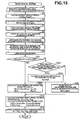
- Fig. 15 there is shown the first modified lane deviation prevention control routine.
- the modified control routine shown in Fig. 15 is also executed as time-triggered interrupt routines to be triggered every predetermined time intervals such as 20 milliseconds.
- the modified control routine of Fig. 15 is similar to the arithmetic and logic processing of Fig. 2 , except that steps S9-S13 included in the routine shown in Fig. 2 are replaced with steps S21-S25 included in the routine shown in Fig. 15 .
- steps S21-S25 will be hereinafter described in detail with reference to the accompanying drawings, while detailed description of steps S1-S8, and S14-S15 will be omitted because the above description thereon seems to be self-explanatory.
- step S8 After the lane-deviation decision has been made based on the picture image data concerning the white lane marker in front of the host vehicle, in other words, a comparison result between lateral-displacement estimate XS and lateral-displacement criterion X C , the routine proceeds from step S8 to step S21.
- step S22 in the same manner as step S10 of Fig. 2 , desired yaw moment Ms, needed to avoid the host vehicle's lane-deviation tendency by execution of LDP control achieved by way of only the yaw moment control, is arithmetically calculated or derived, depending on the state of lane-deviation decision flag F LD .
- F LD ⁇ 0
- the routine flows via step S14 to step S15.
- the automotive LDP apparatus executing the modified LDP control routine shown in Fig. 15 operates as follows.
- step S21 desired yaw moment Ms is calculated or determined based on the state of lane-deviation decision flag F LD and the current host vehicle's lateral displacement, exactly the difference (XS-X C ) between lateral-displacement estimate XS and predetermined lateral-displacement criterion X C .
- step S24 desired deceleration rate Xgs is fixed to preset constant value XgsL so as to execute only the vehicle deceleration control.
- the LDP control system can continuously execute vehicle deceleration control in place of yaw moment control, thus remarkably enhancing the effect of vehicle deceleration control.
- the vehicle-deceleration effect is continued, thereby effectively reducing or eliminating undesirable shock and impact even if a collision or a vehicle roll occurs.
- desired deceleration rate Xgs to be generated by vehicle deceleration control is automatically forcibly fixed to preset constant value XgsL.
- the parameter (XS-X C ) needed to determine desired yaw moment Ms corresponding to the controlled variable of yaw moment control and also to determine desired deceleration rate Xgs corresponding to the controlled variable of vehicle deceleration control cannot be obtained, it is possible to reliably provide a proper effect of vehicle deceleration control.
- the LDP apparatus executing the modified routine of Fig. 15 determines, based on the state of recognition flag Fcr, whether yaw moment control should be enabled, vehicle deceleration control should be enabled, or both of yaw moment control and vehicle deceleration control should be disabled (inhibited).
- the LDP apparatus can determine or estimate a possibility of the host vehicle's lane deviation or a host vehicle's lateral displacement, based on virtual deviation estimate XSv, exactly, a comparison result of virtual deviation estimate XSv and a predetermined lateral-displacement criterion Xcv.
- a virtual-deviation-estimate XSv based lane-deviation decision flag F LDv is reset to "0".
- ⁇ Xcv virtual-deviation-estimate XSv based lane-deviation decision flag F LDv is set.
- vehicle deceleration control may be initiated by setting desired deceleration rate Xgs to a preset constant value and then the vehicle deceleration control may be executed for a predetermined time duration (a preset operating time for vehicle deceleration control).
- recognition flag Fcr calculated at the current execution cycle, is set to "1"
- a count value of a lost counter (or a count-down timer) Lcnt is set to "0".
- recognition flag Fcr calculated at the current execution cycle
- recognition flag Fcr calculated one cycle before
- recognition flag Fcr calculated at the current execution cycle
- recognition flag Fcr calculated at the current execution cycle
- the count value of lost counter Lcnt is set to an initial value Lcnt0, to initiate the count-down operation of lost counter Lcnt.
- Initial value Lcnt0 corresponds to a maximum count value.
- Lcnt a check is made to determine whether the current count value of lost counter Lcnt is greater than "0".
- Lcnt ⁇ 0 virtual deviation estimate XSv is set to "0".
- Fig. 16 there is shown the modified automotive LDP apparatus employing the steering-actuator equipped LDP control system through which a steering torque is automatically produced in a direction that the host vehicle returns to the central axis (the central position) of the driving lane, for lane deviation avoidance.
- a conventional rack-and-pinion steering mechanism is provided between front road wheels 5FL and 5FR.
- the conventional steering mechanism is comprised of at least a rack 24 linked to a steering arm such as a steering knuckle of each front road wheel 5FL (5FR), a pinion 25 in meshed-engagement with rack 24, and a steering shaft 27 through which steering torque is transmitted from steering wheel 21 to pinion gear 25.
- An auto-steering mechanism or an auto-pilot mechanism 28 which constructs a steering actuator (serving as a vehicle yawing motion control actuator) used for automatic steering action or auto-pilot for the front road wheels, is also provided above the pinion 25.
- Auto-steering mechanism 28 is comprised of a driven gear 29 coaxially fixedly connected to steering shaft 27, a drive gear 30 in meshed-engagement with driven gear 29, and an auto-steering motor (or an auto-steering control device) 31 that drives drive gear 30.
- a clutch mechanism 32 is also provided between the motor shaft of auto-steering motor 31 and drive gear 30, for connecting the auto-steering motor shaft to, or disconnecting it from the shaft of drive gear 30. Only during operation of auto-steering mechanism 28, in other words, only during the auto-steering control mode, clutch mechanism 32 is held engaged. During the inoperative state of auto-steering mechanism 28, clutch mechanism 32 is disengaged to prevent input torque created by auto-steering motor 31 from being transmitted to steering shaft 27.
- the steering-actuator equipped LDP control system of the modified automotive LDP apparatus of Fig. 16 is exemplified in a general direct-coupled steering linkage type vehicle steering system using a sole rigid column shaft (steering shaft 27), through which steering wheel 21 is coupled directly to the steering output section linked to steered wheels 5FL and 5FR, and which is rotated by auto-steering motor 31 (auto-steering control means).
- the steering-actuator equipped LDP control system is not limited to such a direct-coupled steering linkage type vehicle steering system using a sole rigid column shaft rotated by auto-steering motor 31.
- the sole rigid column shaft 27 may be replaced by primary and secondary column shafts connected by a universal joint.
- the steering-actuator equipped LDP control system may be constructed by a so-called steer-by-wire (SBW) vehicle steering system in which a steering reaction torque applied to a steering wheel and a steer angle at steered road wheels 5FL and 5FR can be arbitrarily determined.
- SBW steer-by-wire
- the LDP control routine executed by ECU 8 incorporated in the steering-actuator equipped automotive LDP apparatus shown in Fig. 16 is hereunder described in detail in reference to the flow chart shown in Fig. 17 .
- the LDP control routine of Fig. 17 is also executed as time-triggered interrupt routines to be triggered every predetermined sampling time intervals ⁇ T such as 20 milliseconds.
- ⁇ T sampling time interval
- the LDP control routine of Fig. 17 is different from that of Fig. 2 , in that in the system executing the routine of Fig. 17 , instead of controlling braking forces applied to respective road wheels, a desired additional steering torque Tsstr (described later and different from a steering torque manually acting on the steering wheel by the driver) is used for yaw moment control.
- Tsstr a desired additional steering torque Tsstr (described later and different from a steering torque manually acting on the steering wheel by the driver) is used for yaw moment control.
- steps S10-S15 included in the routine shown in Fig. 2 are replaced by steps S31-S36 included in the routine shown in Fig. 17 .
- steps S31-S36 will be hereinafter described in detail with reference to the accompanying drawings, while detailed description of steps S1-S9 will be omitted because the above description thereon seems to be self-explanatory.
- a desired additional steering torque Tsstr needed to avoid the host vehicle's lane-deviation tendency by execution of LDP control achieved by way of only the yaw moment control (only the steering-actuator equipped LDP control system), is arithmetically calculated or derived, depending on the state of lane-deviation decision flag F LD .
- desired additional steering torque Tsstr is arithmetically calculated from the following expression (13), corresponding to a so-called select-MID process according to which a middle value of three values, that is, -Tsstrmax, -K1s ⁇ (XS-X C ), and Tsstrmax is selected as the current value of desired additional steering torque Tsstr.
- Tsstr mi ⁇ - Tsstrmax , - K ⁇ 1 ⁇ s ⁇ XS - X C , Tsstrmax
- Tsstrmax denotes an upper limit of the desired additional steering torque
- -Tsstrmax denotes a lower limit of the desired additional steering torque
- K1s denotes a constant that is determined by specifications of the host vehicle
- (XS-X C ) denotes the difference between lateral-displacement estimate XS and predetermined lateral-displacement criterion X C .
- desired additional steering torque Tsstr is calculated or determined as a controlled variable for feedback control (LDP control).
- LDP control closed-loop feedback control
- desired additional steering torque Tsstr may be estimated and determined such that a desired lateral displacement and a desired sideslip angle of the host vehicle are achieved by way of a vehicle model such as a two-wheel model, in other words, by way of an observer function.
- the routine proceeds to step S35.
- control allotted rate Rxg of vehicle deceleration control to yaw moment control is calculated and determined based on the host vehicle's yaw angle ⁇ . Concretely, control allotted rate Rxg is computed or map-retrieved from the predetermined yaw angle ⁇ versus control allotted rate Rxg characteristic map shown in Fig. 10 . After step S32, step S33 occurs.
- desired deceleration rate Xgs to be generated by vehicle deceleration control is determined depending on the state of lane-deviation decision flag F LD .
- desired additional steering torque Tsstr to be applied to the steering system of the host vehicle by way of yaw moment control based on auto-steering action and executed in parallel with vehicle deceleration control, is arithmetically calculated, depending on the state of lane-deviation decision flag F LD .
- F LD ⁇ 0
- desired additional steering torque Tsstr is arithmetically calculated from the following expression (14).
- Tsstr mid ⁇ - Tsstrmax , - Kms ⁇ K ⁇ 1 ⁇ s ⁇ XS - X C , Tsstrmax
- Tsstrmax denotes an upper limit of the desired additional steering torque
- -Tsstrmax denotes a lower limit of the desired additional steering torque
- K1s denotes a constant that is determined by specifications of the host vehicle
- Kms denotes a proportional gain that is retrieved based on the latest up-to-date informational data of control allotted rate Rxg (set through step S32) from the predetermined control allotted rate Rxg versus proportional gain Kms characteristic map of Fig.
- desired braking forces for the individual road wheels that is, front-left, front-right, rear-left, and rear-right desired wheel-brake cylinder pressures Ps FL , Ps FR , Ps RL and Ps RR , are calculated based on master cylinder pressure Pm read through step S1, desired additional steering torque Tsstr determined through steps S31 or S34, and desired deceleration rate Xgs determined through step S33.
- brake pedal is depressed by the driver's foot and thus the brakes are applied during the automatic vehicle deceleration control.
- step S35 desired driving torque TrqDS is arithmetically calculated as detailed hereunder.
- TrqDS f Acc - g Pmcnt
- f(Acc) is a function of accelerator opening Acc read through step S1 and the function f(Acc) is provided to calculate a desired driving torque that is determined based on the accelerator opening Acc and required to accelerate the host vehicle
- g(Pmcnt) is a function of equivalent controlled master-cylinder pressure Pmcnt and provided to calculate a desired braking torque based on equivalent controlled master-cylinder pressure Pmcnt.
- TrqDS f(Acc).
- command signals corresponding to front-left, front-right, rear-left, and rear-right desired wheel-brake cylinder pressures Ps FL , Ps FR , Ps RL , and Ps RR , calculated through step S35, are output from the input interface of ECU 8 to hydraulic modulator 7, and simultaneously a command signal corresponding to desired driving torque TrqDS, calculated through the same step S35, is output from the output interface of ECU 8 to driving torque control unit 12.
- a command signal corresponding to desired additional steering torque Tsstr calculated through steps S31 or S34, is output from the output interface of ECU 8 to auto-steering motor 31. In this manner, one cycle of the time-triggered interrupt routine of Fig. 17 terminates and the predetermined main program is returned.
- the automotive LDP apparatus executing the modified LDP control routine shown in Fig. 17 operates as follows.
- the processor of ECU 8 determines that there is an increased tendency for the host vehicle to deviate from the current driving lane, and thus a lane-deviation decision flag F LD is set (F LD ⁇ 0).
- the LDP apparatus controls the steering system by means of auto-steering motor 31 in such a manner as to bring the actual additional steering torque closer to desired additional steering torque Tsstr.
- the routine of Fig. 17 flows from step S9 via steps S32-S34 to step S35.
- the yawing moment corresponding to desired additional steering torque Tsstr can be exerted on the host vehicle to effectively reduce or suppress the host vehicle's lane-deviation tendency, and at the same time the proper vehicle deceleration corresponding to desired deceleration rate Xgs can be created to effectively reduce or eliminate undesirable shock and impact even if a collision or a vehicle roll occurs after the host vehicle has deviated from the driving lane.
- the LDP apparatus of Figs. 16-18 employing the steering-actuator equipped LDP control system can provide almost the same effects as the embodiment of Figs. 1-2 , 6-7 , and 9-12 .
- the command signal corresponding to desired additional steering torque Tsstr calculated through steps S31 or S34, is output to auto-steering motor 31, and as a result the automatically-controlled steer angle ⁇ is produced in a direction that the host vehicle returns to the central axis of the current driving lane. Therefore, in the steering-actuator equipped LDP apparatus of Figs.
- auto-steering mechanism 28 serving as a steering actuator, is used to exert a yawing moment on the host vehicle instead of using hydraulic modulator 7, and thus it is possible to generate a desired yawing moment without decelerating the host vehicle and without giving a feeling of uncomfortable vehicle deceleration to the driver.
- the LDP apparatus of Figs. 16-18 is somewhat modified from the LDP apparatus of the embodiment of Figs. 1-2 , 6-7 , and 9-12 , such that a yaw-moment generating unit (yaw-moment generating means) for exerting a yawing moment on the host vehicle is modified from hydraulic modulator 7 to auto-steering mechanism 28.
- the LDP apparatus executing the LDP control routine of Fig. 15 may be further modified, such that a yaw-moment generating unit (yaw-moment generating means) for exerting a yawing moment on the host vehicle is modified from hydraulic modulator 7 to auto-steering mechanism 28.
- step S4 and wheel speed sensors 22FL-22RR serve as a road-surface irregularities detector (road-surface irregularities detection means).
- the process of each of step S12 shown in Fig. 2 , step S24 shown in Fig. 15 , and step S33 shown in Fig. 17 serves as a vehicle deceleration control section (vehicle deceleration control means).
- Wheel speed sensors 22FL-22RR shown in Figs. 1 and 16 serve as a wheel-speed detection means.
- CCD camera 13 shown in Figs. 1 and 16 serves as a picture image pick-up device (picture image pick-up means).
- Camera controller 14 shown in Figs. 1 and 16 serves as a lane marker detector (lane marker detection means).
- the process of step S8 shown in Figs. 2 , 15 and 17 through which lane-deviation decision flag F LD is set or reset depending on the difference (XS-X C ) between lateral-displacement estimate XS and lateral-displacement criterion X C , serves as a lane-deviation tendency detector (lane-deviation tendency detection means).
- Steps S10 and S13-S15 shown in Fig. 2 , or steps S22 and S14-S15 shown in Fig. 15 , or steps S31 and S34-S36 shown in Fig. 17 serve as a lane deviation prevention (LDP) control means.
- LDP lane deviation prevention
- step S11 of Fig. 2 and step S32 of Fig. 17 serves as a control allotted rate decision means.
- Engine/vehicle switches and sensors containing G sensor 15 and yaw rate sensor 16 detecting yaw rate ⁇ ', and the like
- camera controller 14 computing yaw angle ⁇ , lateral displacement X, and curvature ⁇ , serve as a vehicle's driving state and traveling-path condition detection means.
- braking/driving force controlled variable calculation means serves as a braking/driving force controlled variable calculation means.
- Hydraulic modulator 7 and driving torque control unit 12 serve as a braking/driving force control means.
- Auto-steering mechanism 28 and auto-steering control device 31 serves as a steering control means.
- a check for such a state that either one of road wheels of the host vehicle is traveling on road-surface irregularities formed on the white lane marker (the white lane line) or formed outside of and close to the white lane marker, is based on wheel speed Vwi of each road wheel (exactly, comparison results of each wheel acceleration dVwi and its threshold value S limt ).
- a check may be based on a vertical acceleration of a point of the vehicle suspension, moving up and down or a suspension stroke.
- sensor signals from an acceleration sensor a suspension vertical acceleration sensor or G sensor 15 as shown in Figs.
- a stroke sensor commonly used for active suspension control of active suspension system equipped vehicles can also be used for the LDP control system.
- the external recognizing sensor also serving as a vehicle-path detector
- the navigation system and/or CCD camera 13 detects that the host vehicle is traveling within a car parking area except roadways
- a check for the host vehicle traveling on road-surface irregularities formed on the white lane marker may be inhibited to enhance the accuracy of road-surface irregularities detection executed through step S4.
- road-surface irregularities decision flag Fot FL (or Fot FR ) is set, when front-left road wheel 5FL (or front-right road wheel 5FR) is traveling on the road-surface irregularities equidistantly repeatedly formed on the white lane marker by forming the ridged portions (see Fig. 5A ) on the lane marker.
- road-surface irregularities decision flag Fot FL (or Fot FR ) may be set, when front-left road wheel 5FL (or front-right road wheel 5FR) is traveling on the raod-surface irregularities equidistantly repeatedly formed on the white lane marker by forming recessed portions on the lane marker.
- a check for such a state that either one of road wheels of the host vehicle is traveling on road-surface irregularities, formed on the white lane marker, in other words, setting of road-edge decision flag Fdw to "+1" (or to "-1"), is based on front-left and front-right wheel speeds V WFL and V WFR , exactly, comparison results of front-left wheel acceleration dVw FL and its threshold value S limt and front-right wheel acceleration dVw FR and its threshold value S limt .
- road-edge decision flag Fdw may be based on rear-left and rear-right wheel speeds Vw RL and Vw RR , exactly, comparison results of rear-left wheel acceleration dVw RL and its threshold value S limtR and rear-right wheel acceleration dVw RR and its threshold value S limtR . That is to say, when the processor of ECU 8 determines that either one of four road wheels of the host vehicle is traveling on road-surface irregularities, road-edge decision flag Fdw may be set.
Claims (20)
- Dispositif de prévention d'une déviation de la voie pour une automobile (LDP), comprenant :un détecteur des irrégularités de la surface de la route (22FL-22RR, S4), détectant si un véhicule hôte se trouve dans un état dans lequel le véhicule hôte roule sur des irrégularités de la surface de la route formées sur une ligne de marquage d'une voie ou près de celle-ci, et agencées le long de la ligne de marquage de la voie ;un dispositif de prise d'images (13) pour assurer la reconnaissance du marquage de la voie ;un actionneur (7), capable de décélérer le véhicule hôte ; etune unité de commande (8), configurée de sorte à être connectée électroniquement au détecteur des irrégularités de la surface de la route (22FL-22RR, S4), au dispositif de prise d'images (13) et à l'actionneur (7) pour des objectifs de contrôle du LPD ; l'unité de commande (8) comprenant :une section de commande de la décélération du véhicule (S12 ; S24 ; S33), exécutant, dans un état de non reconnaissance du marquage de la voie, dans lequel le marquage de la voie ne peut pas être détecté, une commande de décélération du véhicule pour décélérer de manière active le véhicule hôte lorsque le véhicule hôte se trouve dans l'état dans lequel le véhicule hôte roule sur les irrégularités de la surface de la route.
- Dispositif LDP selon la revendication 1, dans lequel :
le détecteur des irrégularités de la surface de la route (22FL-22RR, S4) comprend des capteurs de la vitesse des roues (22FL-22RR), détectant les vitesses respectives (VwFL=VwRR) des roues du véhicule hôte ; et
le détecteur des irrégularités de la surface de la route (22FL-22RR, S4) détermine, sur la base des vitesses des roues (VwFL=VwRR si le véhicule hôte se trouve dans l'état dans lequel le véhicule hôte roule sur les irrégularités de la surface de la route. - Dispositif LPD selon la revendication 2, dans lequel :le détecteur des irrégularités de la route (22FL-22RR, S4) détermine que le véhicule hôte se trouve dans l'état dans lequel le véhicule hôte roule sur les irrégularités de la surface de la route lors d'une fluctuation de l'une des vitesses de la roue de droite ou de la roue de gauche.
- Dispositif LPD selon les revendications 2 ou 3, dans lequel :le détecteur des irrégularités de la route (22FL-22RR, S4) détermine que le véhicule hôte se trouve dans l'état dans lequel le véhicule hôte roule sur les irrégularités de la surface de la route lors d'une fluctuation de la vitesse des roues pendant une période de temps pratiquement constante, déterminée sur la base d'une vitesse du véhicule hôte (V).
- Dispositif LDP selon l'une des revendications 2 à 4, comprenant en outre :un détecteur des informations concernant la position d'un véhicule hôte (13, 14), détectant des informations sur la position concernant une position du véhicule hôte sur une carte ;le détecteur des irrégularités de la route (22FL-22RR, S4) déterminant, sur la base des informations concernant la position du véhicule hôte et des vitesses des roues, que le véhicule hôte se trouve dans l'état dans lequel le véhicule hôte roule sur les irrégularités de la surface de la route, lorsque la vitesse des roues du véhicule hôte, roulant sur une voie de circulation, fluctue.
- Dispositif LDP selon la revendication 1, comprenant en outre :un capteur du déplacement vers le haut et vers le bas de la suspension du véhicule (15), détectant un déplacement vers le haut et vers le bas d'une suspension du véhicule hôte ;le détecteur des irrégularités de la route (22FL-22RR, S4) déterminant, sur la base du déplacement vers le haut et vers le bas détecté de la suspension, si le véhicule hôte se trouve dans un état dans lequel le véhicule hôte roule sur les irrégularités de la surface de la route.
- Dispositif LDP selon l'une des revendications 1 à 6, comprenant en outre :un dispositif de prise d'images (13), prenant une image devant le véhicule hôte ; etun détecteur du marquage de la voie (14), détectant une ligne de marquage de la voie sur une voie de circulation du véhicule hôte, sur la base de l'image prise par le dispositif de prise d'images (13) ;l'unité de commande (8) comprenant en outre :une section de détection d'une tendance à une déviation de la voie (S8), déterminant, en fonction d'une déviation latérale du véhicule hôte estimée sur la base de la ligne de marquage de la voie, si le véhicule hôte se trouve dans un état dans lequel le véhicule hôte présente une tendance accrue à une déviation de la voie de circulation ou dans un état dans lequel le véhicule hôte présente une tendance réduite à une déviation de la voie de circulation ; etune section de commande du LDP (S10, S13-S15 ; S22, S14-S15 ; S31, S34-S36), exécutant une commande du moment de lacet, permettant d'empêcher une tendance à la déviation de la voie du véhicule hôte, lorsque le véhicule hôte se trouve dans l'état dans lequel le véhicule hôte présente une tendance accrue à une déviation de la voie de circulation.
- Dispositif LDP selon la revendication 7, dans lequel :la section de commande de la décélération du véhicule (S12 ; S24 ; S33) détermine une variable réglée de la commande de la décélération du véhicule (Xgs), basée sur la déviation latérale du véhicule hôte.
- Dispositif LDP selon les revendications 7 ou 8, comprenant en outre :un détecteur de l'état de conduite et du trajet de déplacement du véhicule (14-16), détectant au moins un état de conduite (ϕ) du véhicule hôte ;l'unité de commande (8) comprenant une section de décision d'un rapport associé à la commande (S11 ; S32), déterminant, sur la base de l'état de conduite (ϕ), un rapport associé à la commande (Rxg) entre la commande de décélération du véhicule et la commande du moment de lacet, la commande de décélération du véhicule et la commande du moment de lacet étant exécutées sur la base du rapport associé à la commande (Rxg).
- Dispositif LDP selon la revendication 9, dans lequel :le détecteur de l'état de conduite et de l'état du trajet de déplacement du véhicule (14-16), détecte au moins une caractéristique, la vitesse du véhicule hôte (V), une vitesse de lacet (ϕ), résultant d'un moment de lacet agissant sur le véhicule hôte, une accélération latérale (Yg) exercée sur le véhicule hôte, un angle de lacet (ϕ) par rapport à un sens de la voie de circulation du véhicule hôte, ou une courbure (β) de la voie de circulation du véhicule hôte.
- Dispositif LDP selon l'une des revendications 7 à 10, dans lequel :l'unité de commande (8) comprend en outre :une section de détection d'un état de non reconnaissance du marquage de la voie (S1, S2), déterminant si le véhicule hôte se trouve dans un état de non reconnaissance du marquage de la voie, dans lequel la ligne de marquage de la voie ne peut pas être détectée par le dispositif de prise d'images (13), ou dans un état de reconnaissance du marquage de la voie, dans lequel la ligne de marquage de la voie peut être détectée par le dispositif de prise d'images (13) ;la section de commande de la décélération du véhicule (Xgs) fixant une variable réglée de la commande de la décélération du véhicule (Xgs) à une valeur constante prédéterminée (XgsL), lorsque la section de détection de l'état de non reconnaissance du marquage de la voie (S1, S2) détermine que le véhicule hôte se trouve dans l'état de non reconnaissance du marquage de la voie, le détecteur des irrégularités de la route (22FL-22RR, S4) déterminant en outre que le véhicule hôte se trouve dans l'état dans lequel le véhicule hôte roule sur les irrégularités de la surface de la route.
- Dispositif LDP selon l'une des revendications 7 à 10, dans lequel :l'unité de commande (8) comprend en outre :une section de détection d'un état de non reconnaissance du marquage de la voie (S1, S2), déterminant si le véhicule hôte se trouve dans un état de non reconnaissance du marquage de la voie, dans lequel la ligne de marquage de la voie ne peut pas être détectée par le dispositif de prise d'images (13), ou dans un état de reconnaissance du marquage de la voie, dans lequel la ligne de marquage de la voie peut être détectée par le dispositif de prise d'images (13) ; etune section d'estimation d'un risque de déviation de la voie basée sur une estimation d'une déviation virtuelle, estimant, en fonction d'une estimation d'une déviation virtuelle (XSv), estimée sur la base de données historiques (ϕo, Xo, βo), concernant un état de conduite d'un véhicule et un état du trajet de déplacement du véhicule hôte, toutes obtenues juste avant une transition de l'état de reconnaissance du marquage de la voie vers l'état de non reconnaissance de la voie, si le véhicule hôte se trouve dans un état dans lequel le véhicule hôte présente un risque élevé d'une déviation de la voie de circulation ou dans un état dans lequel le véhicule hôte présente un risque réduit d'une déviation de la voie de circulation ;la section de commande de la décélération du véhicule (S24) fixant une variable réglée de la commande de la décélération du véhicule (Xgs) à une valeur constante prédéterminée (XgsL), lorsque la section d'estimation du risque d'une déviation de la voie basée sur une estimation de déviation virtuelle détermine que le véhicule hôte se trouve dans l'état dans lequel le véhicule hôte présente un risque élevé d'une déviation de la voie de circulation, dans l'état de non reconnaissance du marquage de la voie, le détecteur des irrégularités de la route (22FL-22RR, S4) déterminant en outre que le véhicule hôte se trouve dans l'état dans lequel le véhicule hôte roule sur les irrégularités de la surface de la route.
- Dispositif LDP selon l'une des revendications 9 à 12, dans lequel :le détecteur de l'état de conduite et de l'état du trajet de déplacement du véhicule (14-16) détecte une vitesse du véhicule hôte (V), un angle de lacet (ϕ) par rapport à un sens de la voie de circulation du véhicule hôte, un déplacement latéral (X) du véhicule hôte par rapport à un axe central de la voie de circulation, et une courbure (β) de la voie de circulation du véhicule hôte ;la section de détection d'une tendance à la déviation de la voie (S8) évalue une estimation du déplacement latéral futur (XS) sur la base de la vitesse du véhicule hôte (V), de l'angle de lacet (ϕ), du déplacement latéral (X) et de la courbure (β) ; etla section de détection d'une tendance à la déviation de la voie (SS) détermine que le véhicule hôte se trouve dans un état dans lequel le véhicule hôte présente une tendance accrue à une déviation de la voie de circulation, lorsqu'une valeur absolue (|XS|) de l'estimation du déplacement latéral futur (XS) est supérieure ou égale à un critère du déplacement latéral prédéterminé (Xc).
- Dispositif LDP selon l'une des revendications 7 à 13, comprenant en outre :un dispositif de commande de la force de freinage/d'entraînement (7, 12), contrôlant les forces de freinage/d'entraînement des roues;la section de commande du LDP (S10, S13-S15 ; S22, S14-S15 ; S31, S34-S36) comprenant une section de calcul d'une variable réglée de la force de freinage/d'entraînement (S14-S15 ; S35-S36), calculant une variable réglée de la force de freinage/d'entraînement (Pi, TrqDS) de chacune des roues, de sorte à produire un moment de lacet dans une direction dans laquelle la tendance à une déviation de la voie du véhicule hôte est empêchée, lorsque la section de la détection d'une tendance à la déviation de la voie (S8) détermine que le véhicule hôte se trouve dans l'état dans lequel le véhicule hôte présente une tendance accrue à une déviation de la voie de circulation ; etle dispositif de commande de la force de freinage/d'entraînement (7, 12) contrôlant les forces de freinage/d'entraînement des roues en réponse aux variables réglées de la force de freinage/d'entraînement calculées.
- Dispositif LDP selon la revendication 14, dans lequel :le dispositif de commande de la force de freinage/d'entraînement comprend un modulateur hydraulique (7), capable de contrôler les forces de freinage des roues indépendamment d'un actionnement de la pédale de frein par un conducteur.
- Dispositif LDP selon les revendications 14 ou 15, dans lequel :la section de calcul de la variable réglée de la force de freinage/d'entraînement (S14-S15 ; S35-S36) calcule les variables réglées de la force de freinage/d'entraînement des roues respectives en fonction d'un moment de lacet voulu (Ms), calculé sur la base d'une différence (XS-Xc) entre l'estimation du déplacement latéral futur (XS) et du critère du déplacement latéral prédéterminé (Xc).
- Dispositif LDP selon l'une des revendications 7 à 13, comprenant en outre :un dispositif de commande de direction (28, 31), contrôlant un couple de direction appliqué à un système de direction du véhicule hôte indépendamment de l'action de direction d'un conducteur ;la section de commande du LDP (S31, S34-S36) comprenant une section de calcul d'une variable réglée du couple de direction (S31, S34, S36), calculant une variable réglée du couple de direction (Tsstr) du système de direction, de sorte à produire un moment de lacet dans une direction dans laquelle une tendance à la déviation de la voie du véhicule hôte est empêchée, lorsque la section de détection d'une tendance à la déviation de la voie (S8) détermine que le véhicule hôte se trouve dans un état dans lequel le véhicule hôte présente une tendance accrue à une déviation de la voie de circulation ; etle dispositif de commande de direction (28, 31) contrôlant le couple de direction appliqué au système de direction en réponse à la variable réglée du couple de direction calculée (Tsstr).
- Procédé permettant d'empêcher une déviation de la voie d'un véhicule hôte, utilisant des actionneurs de la force de freinage, ajustant les forces de freinage appliquées aux roues respectives, le procédé comprenant les étapes ci-dessous :(a1) détection du fait de savoir si un véhicule hôte se trouve dans un état dans lequel le véhicule hôte roule sur des irrégularités de la surface de la route formées sur la ligne de marquage de la voie ou près de celle-ci, et agencées le long de la ligne de marquage de la voie ;(a2) détection de la ligne de marquage de la voie par un dispositif de prise d'images (13) en vue de la reconnaissance du marquage de la voie ; et(b) exécution, dans un état de non reconnaissance du marquage de la voie, dans lequel la ligne de marquage de la voie ne peut pas être détectée, d'une commande de décélération du véhicule, entraînant une décélération active du véhicule hôte lorsque le véhicule hôte se trouve dans l'état dans lequel le véhicule hôte roule sur les irrégularités de la surface de la route.
- Procédé selon la revendication 18, comprenant en outre l'étape ci-dessous :(c) exécution, dans l'état de non reconnaissance du marquage de la voie, d'une commande du moment de lacet, entraînant l'application active d'un moment de lacet au véhicule hôte, de manière simultanée à la commande de décélération active du véhicule, lorsque le véhicule hôte se trouve dans l'état dans lequel le véhicule hôte roule sur les irrégularités de la surface de la route.
- Procédé selon la revendication 18, comprenant en outre les étapes ci-dessous :(d) détermination du fait de savoir si le véhicule hôte se trouve dans l'état de non reconnaissance du marquage de la voie, dans lequel la ligne de marquage de la voie ne peut pas être détectée par le dispositif de prise d'images (13), ou dans un état de reconnaissance du marquage de la voie, dans lequel la ligne de marquage de la voie peut être détectée par le dispositif de prise d'images (13) ;(e) fixation d'un taux de décélération voulu (Xgs) de la commande de décélération active du véhicule à une valeur constante prédéterminée (XgsL) lorsque le véhicule hôte se trouve dans l'état dans lequel le véhicule hôte roule sur les irrégularités de la surface de la route dans l'état de non reconnaissance du marquage de la route.
Applications Claiming Priority (2)
| Application Number | Priority Date | Filing Date | Title |
|---|---|---|---|
| JP2003404632 | 2003-12-03 | ||
| JP2003404632A JP4389567B2 (ja) | 2003-12-03 | 2003-12-03 | 車線逸脱防止装置 |
Publications (3)
| Publication Number | Publication Date |
|---|---|
| EP1538019A2 EP1538019A2 (fr) | 2005-06-08 |
| EP1538019A3 EP1538019A3 (fr) | 2006-08-23 |
| EP1538019B1 true EP1538019B1 (fr) | 2010-01-20 |
Family
ID=34463979
Family Applications (1)
| Application Number | Title | Priority Date | Filing Date |
|---|---|---|---|
| EP04257555A Active EP1538019B1 (fr) | 2003-12-03 | 2004-12-03 | Dispositif pour la prévention de la déviation hors de la voie pour une automobile |
Country Status (4)
| Country | Link |
|---|---|
| US (1) | US7698032B2 (fr) |
| EP (1) | EP1538019B1 (fr) |
| JP (1) | JP4389567B2 (fr) |
| DE (1) | DE602004025191D1 (fr) |
Cited By (2)
| Publication number | Priority date | Publication date | Assignee | Title |
|---|---|---|---|---|
| US11527154B2 (en) | 2020-02-20 | 2022-12-13 | Toyota Motor North America, Inc. | Wrong way driving prevention |
| US11603094B2 (en) | 2020-02-20 | 2023-03-14 | Toyota Motor North America, Inc. | Poor driving countermeasures |
Families Citing this family (116)
| Publication number | Priority date | Publication date | Assignee | Title |
|---|---|---|---|---|
| JP3606276B2 (ja) * | 2002-11-26 | 2005-01-05 | 日産自動車株式会社 | 車線逸脱防止装置 |
| JP3900099B2 (ja) * | 2003-03-20 | 2007-04-04 | 日産自動車株式会社 | 車線逸脱防止装置 |
| JP3873919B2 (ja) * | 2003-03-20 | 2007-01-31 | 日産自動車株式会社 | 車線逸脱防止装置 |
| JP4013825B2 (ja) * | 2003-05-22 | 2007-11-28 | 日産自動車株式会社 | 車両用走行制御装置 |
| US7200478B2 (en) * | 2003-10-31 | 2007-04-03 | Nissan Motor Co., Ltd. | Lane departure prevention apparatus |
| KR20060049706A (ko) * | 2004-07-20 | 2006-05-19 | 아이신세이끼가부시끼가이샤 | 차량의 레인주행지원장치 |
| JP4131268B2 (ja) * | 2005-02-02 | 2008-08-13 | トヨタ自動車株式会社 | 車輌の制駆動力制御装置 |
| US7219031B2 (en) * | 2005-03-31 | 2007-05-15 | Nissan Technical Center North America, Inc. | Rumble strip responsive systems: discrimination of types of rumble strips |
| JP4816732B2 (ja) * | 2005-12-01 | 2011-11-16 | トヨタ自動車株式会社 | 運転支援システムおよび運転支援方法 |
| WO2007102228A1 (fr) * | 2006-03-06 | 2007-09-13 | Hitachi, Ltd. | dispositif de commande et procédé pour automobile |
| US20070225914A1 (en) * | 2006-03-21 | 2007-09-27 | Hiroshi Kawazoe | Lane departure avoidance control |
| US9387838B2 (en) * | 2006-04-12 | 2016-07-12 | Krayon Systems Inc. | Vehicle braking apparatus system and method |
| DE102006017929A1 (de) * | 2006-04-18 | 2007-10-25 | Robert Bosch Gmbh | Fahrerassistenzsystem |
| JP5093552B2 (ja) * | 2006-05-09 | 2012-12-12 | 株式会社ジェイテクト | 車両用操舵装置 |
| JP4793094B2 (ja) * | 2006-05-17 | 2011-10-12 | 株式会社デンソー | 走行環境認識装置 |
| JP2008018923A (ja) * | 2006-06-16 | 2008-01-31 | Nissan Motor Co Ltd | 車両用制動制御装置及び車両制動制御方法 |
| SE530446C2 (sv) * | 2006-10-24 | 2008-06-10 | Volvo Lastvagnar Ab | Körbanedetekteringssystem |
| US8060275B2 (en) * | 2007-01-19 | 2011-11-15 | Ford Global Technologies, Llc | Rough road detection system used in an on-board diagnostic system |
| JP5311793B2 (ja) * | 2007-10-16 | 2013-10-09 | トヨタ自動車株式会社 | 脇見状態判定装置 |
| JP4550910B2 (ja) * | 2008-03-04 | 2010-09-22 | 三菱電機株式会社 | 車両挙動検出装置 |
| US7898400B2 (en) | 2008-04-15 | 2011-03-01 | Autoliv Asp, Inc. | Enhanced vision road detection system |
| US8428843B2 (en) * | 2008-06-20 | 2013-04-23 | GM Global Technology Operations LLC | Method to adaptively control vehicle operation using an autonomic vehicle control system |
| DK176913B1 (da) * | 2008-06-27 | 2010-04-26 | Bent Neubauer Holding Aps | Elektronisk parkeringsskive |
| US9520004B2 (en) | 2008-06-27 | 2016-12-13 | Bent Neubauer Holding Aps | Electronic parking disc |
| US8099205B2 (en) * | 2008-07-08 | 2012-01-17 | Caterpillar Inc. | Machine guidance system |
| JP5359516B2 (ja) * | 2008-07-29 | 2013-12-04 | 日産自動車株式会社 | 車両運転支援装置及び車両運転支援方法 |
| US9283910B2 (en) * | 2008-12-09 | 2016-03-15 | Toyota Jidosha Kabushiki Kaisha | Object detection apparatus and object detection method |
| DE102009000079A1 (de) * | 2009-01-08 | 2010-07-15 | Robert Bosch Gmbh | Verfahren und Steuergerät zur Erkennung eines gefährlichen Fahrzustandes eines Fahrzeugs |
| JP5407952B2 (ja) * | 2009-06-18 | 2014-02-05 | 日産自動車株式会社 | 車両運転支援装置及び車両運転支援方法 |
| DE102010038846A1 (de) | 2009-08-05 | 2011-02-10 | Advics Co., Ltd, Kariya-city | Bewegungssteuervorrichtung für ein Fahrzeug |
| US8306672B2 (en) * | 2009-09-09 | 2012-11-06 | GM Global Technology Operations LLC | Vehicular terrain detection system and method |
| JP5428737B2 (ja) * | 2009-10-15 | 2014-02-26 | 日産自動車株式会社 | 路外逸脱防止装置 |
| CN102548821B (zh) * | 2010-04-07 | 2016-01-20 | 丰田自动车株式会社 | 车辆行驶辅助装置 |
| US20110301813A1 (en) * | 2010-06-07 | 2011-12-08 | Denso International America, Inc. | Customizable virtual lane mark display |
| JP5510172B2 (ja) * | 2010-08-09 | 2014-06-04 | 日産自動車株式会社 | 車両制御装置 |
| JP5505183B2 (ja) * | 2010-08-09 | 2014-05-28 | 日産自動車株式会社 | 振動付与構造検出装置及び車両制御装置 |
| JP5817097B2 (ja) * | 2010-09-24 | 2015-11-18 | 日産自動車株式会社 | 車両制御装置 |
| JP5429126B2 (ja) * | 2010-10-01 | 2014-02-26 | トヨタ自動車株式会社 | 走行支援装置及び方法 |
| JP5510255B2 (ja) * | 2010-10-01 | 2014-06-04 | トヨタ自動車株式会社 | 車両の操作状態判定システム |
| US8527172B2 (en) * | 2010-10-20 | 2013-09-03 | GM Global Technology Operations LLC | Vehicle collision avoidance and warning system |
| WO2012068331A1 (fr) | 2010-11-19 | 2012-05-24 | Magna Electronics Inc. | Système de suivi de voie et système de centrage de voie |
| WO2013098996A1 (fr) * | 2011-12-28 | 2013-07-04 | トヨタ自動車株式会社 | Dispositif d'aide à la conduite de véhicule |
| US9298991B2 (en) * | 2012-01-17 | 2016-03-29 | LimnTech LLC | GPS-based machine vision roadway mark locator, inspection apparatus, and marker |
| US10301783B2 (en) | 2012-01-17 | 2019-05-28 | LimnTech LLC | Roadway maintenance striping control system |
| US8935057B2 (en) | 2012-01-17 | 2015-01-13 | LimnTech LLC | Roadway mark data acquisition and analysis apparatus, systems, and methods |
| US9784843B2 (en) | 2012-01-17 | 2017-10-10 | Limn Tech LLC | Enhanced roadway mark locator, inspection apparatus, and marker |
| JP5543501B2 (ja) * | 2012-01-27 | 2014-07-09 | 株式会社日本自動車部品総合研究所 | 車両制御装置 |
| DE102012004791A1 (de) * | 2012-03-07 | 2013-09-12 | Audi Ag | Verfahren zum Warnen des Fahrers eines Kraftfahrzeugs vor einer sich anbahnenden Gefahrensituation infolge eines unbeabsichtigten Driftens auf eine Gegenverkehrsfahrspur |
| US9701245B2 (en) | 2012-06-22 | 2017-07-11 | GM Global Technology Operations LLC | Alert systems and methods for a vehicle |
| US9153108B2 (en) | 2012-06-22 | 2015-10-06 | GM Global Technology Operations LLC | Alert systems and methods for a vehicle |
| US9349263B2 (en) * | 2012-06-22 | 2016-05-24 | GM Global Technology Operations LLC | Alert systems and methods for a vehicle |
| US9123215B2 (en) | 2012-06-22 | 2015-09-01 | GM Global Technology Operations LLC | Alert systems and methods for a vehicle |
| US9132774B2 (en) | 2012-06-22 | 2015-09-15 | GM Global Technology Operations LLC | Alert systems and methods for a vehicle |
| US9266451B2 (en) | 2012-06-22 | 2016-02-23 | GM Global Technology Operations LLC | Alert systems and methods for a vehicle |
| US9493116B2 (en) | 2012-06-22 | 2016-11-15 | GM Global Technology Operations LLC | Alert systems and methods for a vehicle |
| WO2014006770A1 (fr) * | 2012-07-06 | 2014-01-09 | 本田技研工業株式会社 | Appareil de commande de déplacement de véhicule |
| US8473144B1 (en) | 2012-10-30 | 2013-06-25 | Google Inc. | Controlling vehicle lateral lane positioning |
| US9457806B2 (en) * | 2012-11-27 | 2016-10-04 | Nissan Motor Co., Ltd. | Vehicular acceleration suppression device and vehicular acceleration suppression method |
| MX340659B (es) * | 2013-01-11 | 2016-07-20 | Nissan Motor | Aparato de control de desplazamiento de vehiculo y metodo de control de desplazamiento de vehiculo. |
| US8948972B2 (en) | 2013-03-01 | 2015-02-03 | Nissan North America, Inc. | Vehicle controlling system and method |
| US20140277833A1 (en) * | 2013-03-15 | 2014-09-18 | Mighty Carma, Inc. | Event triggered trip data recorder |
| JP6172451B2 (ja) * | 2013-08-12 | 2017-08-02 | マツダ株式会社 | 車両用制動装置 |
| US20150153456A1 (en) * | 2013-12-02 | 2015-06-04 | Hemisphere Gnss Inc. | Integrated machine guidance system |
| US9199642B2 (en) | 2014-01-21 | 2015-12-01 | Elwha Llc | Vehicle collision management responsive to traction conditions in an avoidance path |
| US9139202B2 (en) | 2014-01-21 | 2015-09-22 | Elwha Llc | Vehicle collision management responsive to adverse circumstances in an avoidance path |
| JP6119634B2 (ja) * | 2014-02-21 | 2017-04-26 | トヨタ自動車株式会社 | 車両の自動運転制御方法 |
| US9334681B2 (en) * | 2014-10-03 | 2016-05-10 | Continental Automotive Systems, Inc. | Automatic door child safety lock release in a crash event |
| EP3213251A1 (fr) * | 2014-10-27 | 2017-09-06 | FTS Computertechnik GmbH | Surveillance de vision artificielle pour système de vision artificielle |
| JP2016091259A (ja) * | 2014-11-04 | 2016-05-23 | いすゞ自動車株式会社 | 警報装置 |
| JP2016101892A (ja) * | 2014-11-28 | 2016-06-02 | 株式会社アドヴィックス | 衝突回避装置 |
| KR102310281B1 (ko) * | 2014-12-05 | 2021-10-07 | 현대모비스 주식회사 | 차선 유지를 위한 차량 조향 제어 장치 및 방법 |
| US9946940B2 (en) | 2014-12-18 | 2018-04-17 | Magna Electronics Inc. | Vehicle vision system with adaptive lane marker detection |
| US10713506B2 (en) | 2014-12-18 | 2020-07-14 | Magna Electronics Inc. | Vehicle vision system with 3D registration for distance estimation |
| JP6115576B2 (ja) * | 2015-01-07 | 2017-04-19 | トヨタ自動車株式会社 | 車両走行制御装置 |
| JP6123812B2 (ja) * | 2015-01-29 | 2017-05-10 | トヨタ自動車株式会社 | 車線追従制御装置 |
| US9499202B2 (en) * | 2015-04-15 | 2016-11-22 | Delphi Technologies, Inc. | Steering system and method for autonomous vehicles |
| US10449899B2 (en) | 2015-05-08 | 2019-10-22 | Magna Electronics Inc. | Vehicle vision system with road line sensing algorithm and lane departure warning |
| KR101848360B1 (ko) * | 2015-11-03 | 2018-05-29 | 넥센타이어 주식회사 | 차량의 차선이탈 방지 시스템 및 방법 |
| DE102016000209A1 (de) * | 2016-01-11 | 2017-07-13 | Trw Automotive Gmbh | Steuerungs-System und Verfahren zum Ermitteln einer Straßenbelagsunregelmäßigkeit |
| JP2017134520A (ja) * | 2016-01-26 | 2017-08-03 | トヨタ自動車株式会社 | 車両用衝突回避支援システム |
| US10055651B2 (en) | 2016-03-08 | 2018-08-21 | Magna Electronics Inc. | Vehicle vision system with enhanced lane tracking |
| US20170305398A1 (en) * | 2016-04-22 | 2017-10-26 | Hon Hai Precision Industry Co., Ltd. | Brake assistant control system and method thereof |
| US20170327035A1 (en) * | 2016-05-10 | 2017-11-16 | Ford Global Technologies, Llc | Methods and systems for beyond-the-horizon threat indication for vehicles |
| JP6809020B2 (ja) * | 2016-07-27 | 2021-01-06 | いすゞ自動車株式会社 | 操舵補助装置及び操舵補助方法 |
| JP6520874B2 (ja) * | 2016-09-12 | 2019-05-29 | トヨタ自動車株式会社 | 車両制御装置 |
| US10343685B2 (en) * | 2016-09-28 | 2019-07-09 | Baidu Usa Llc | Physical model and machine learning combined method to simulate autonomous vehicle movement |
| JP6544341B2 (ja) * | 2016-11-25 | 2019-07-17 | トヨタ自動車株式会社 | 車両運転支援装置 |
| JP6922297B2 (ja) * | 2017-03-21 | 2021-08-18 | 三菱自動車工業株式会社 | 運転支援システム |
| US20180273051A1 (en) * | 2017-03-24 | 2018-09-27 | Bendix Commercial Vehicle Sytems LLC | Controller and Method of Setting an Intervention Zone in a Lane Departure Warning System |
| EP3405374B1 (fr) * | 2017-03-30 | 2020-10-28 | Baidu.com Times Technology (Beijing) Co., Ltd. | Système de vérification de direction à base de bordure de décélération et de maintien de voie pour véhicules à conduite autonome |
| EP3389026A1 (fr) * | 2017-04-12 | 2018-10-17 | Volvo Car Corporation | Appareil et procédé d'assistance au conducteur d'un véhicule routier |
| KR102254973B1 (ko) * | 2017-04-25 | 2021-05-24 | 현대모비스 주식회사 | 주행 차선 안내 장치 및 그 제어 방법 |
| US10633027B2 (en) * | 2017-06-21 | 2020-04-28 | Toyota Research Institute, Inc. | Enhanced virtual lane marker data for conveying a vehicle operational state |
| CN109387210B (zh) * | 2017-08-02 | 2022-03-29 | 腾讯科技(深圳)有限公司 | 车辆导航方法及其装置 |
| KR102335761B1 (ko) * | 2017-08-07 | 2021-12-06 | 주식회사 만도 | 전동식 파워 스티어링 시스템 및 그 제어 방법 |
| DE202017107397U1 (de) * | 2017-12-05 | 2017-12-20 | Hochschule Für Technik Und Wirtschaft Des Saarlandes | Vorrichtung zur Warnung eines Zweiradfahrers vor einer Kollision mit einem anderen Fahrzeug |
| JP6847876B2 (ja) * | 2018-01-29 | 2021-03-24 | 株式会社東芝 | 情報処理装置、情報処理システム、および情報処理方法 |
| US11029688B2 (en) | 2018-02-12 | 2021-06-08 | Motional Ad Llc | Rumble strip following for automated vehicle steering |
| JP6986463B2 (ja) * | 2018-02-13 | 2021-12-22 | 日立Astemo株式会社 | 運転支援装置、運転支援方法及び運転支援システム |
| DE102018203560A1 (de) * | 2018-03-08 | 2019-09-12 | Bayerische Motoren Werke Aktiengesellschaft | Verfahren und Steuereinheit zur Erkennung einer Fahrspurbegrenzung |
| JP6861669B2 (ja) * | 2018-06-15 | 2021-04-21 | 本田技研工業株式会社 | 車両制御装置、車両制御方法、およびプログラム |
| CN108859953A (zh) * | 2018-06-19 | 2018-11-23 | 奇瑞汽车股份有限公司 | 防止车道偏离的车辆控制方法和装置 |
| KR20200022676A (ko) * | 2018-08-23 | 2020-03-04 | 현대자동차주식회사 | 차량의 거동 제어 장치 및 그 방법 |
| WO2020061932A1 (fr) * | 2018-09-27 | 2020-04-02 | 深圳市大疆创新科技有限公司 | Procédé et système d'alerte précoce de déplacement de véhicule, véhicule et support d'enregistrement |
| DE102019206875B3 (de) | 2019-05-13 | 2020-07-23 | Volkswagen Aktiengesellschaft | Erkennen einer Bankettfahrt eines Kraftfahrzeugs |
| KR102637348B1 (ko) * | 2019-06-10 | 2024-02-21 | 에이치엘만도 주식회사 | 스티어 바이 와이어 시스템의 노면 충격 모사 장치 |
| JP7140077B2 (ja) * | 2019-09-02 | 2022-09-21 | トヨタ自動車株式会社 | 衝突回避支援装置 |
| DE102019213850A1 (de) | 2019-09-11 | 2020-05-28 | Zf Friedrichshafen Ag | Verfahren zur Spurführung eines autonomen Fahrzeugs |
| KR20210031075A (ko) * | 2019-09-11 | 2021-03-19 | 주식회사 만도 | 조향 제어 장치 및 그 방법, 그리고 조향 시스템 |
| KR20210149374A (ko) * | 2020-06-02 | 2021-12-09 | 현대자동차주식회사 | 전방 차량 브레이킹 레벨 제공 장치 및 그의 브레이킹 레벨 제공 방법 |
| CN112373477B (zh) * | 2020-11-23 | 2023-03-28 | 重庆长安汽车股份有限公司 | 自动驾驶系统的冗余控制方法、自动驾驶系统、汽车、控制器及计算机可读存储介质 |
| CN112562119B (zh) * | 2020-12-10 | 2023-05-12 | 平安科技(深圳)有限公司 | 辅助驾驶中的压线检测方法、装置及计算机设备 |
| US11702133B2 (en) * | 2021-04-21 | 2023-07-18 | GM Global Technology Operations LLC | Yaw stability control system for a motor vehicle |
| CN113255553B (zh) * | 2021-06-04 | 2022-09-23 | 清华大学 | 一种基于振动信息监督的可持续学习方法 |
| DE102022206519A1 (de) * | 2022-06-28 | 2023-12-28 | Volkswagen Aktiengesellschaft | Verfahren und Vorrichtung zur Handerkennung an einem Lenkrad eines Fahrzeuges |
| CN115892075B (zh) * | 2023-01-06 | 2023-06-09 | 阿里巴巴达摩院(杭州)科技有限公司 | 轨迹规划方法、自动驾驶设备及计算机存储介质 |
Family Cites Families (30)
| Publication number | Priority date | Publication date | Assignee | Title |
|---|---|---|---|---|
| US4361202A (en) * | 1979-06-15 | 1982-11-30 | Michael Minovitch | Automated road transportation system |
| JPH03243453A (ja) * | 1990-02-21 | 1991-10-30 | Mitsubishi Electric Corp | 車両の対地速度検出装置 |
| GB9317983D0 (en) * | 1993-08-28 | 1993-10-13 | Lucas Ind Plc | A driver assistance system for a vehicle |
| JPH07160993A (ja) * | 1993-12-13 | 1995-06-23 | Toyota Motor Corp | 車両のレーン維持制御装置 |
| JPH0920223A (ja) * | 1995-07-07 | 1997-01-21 | Nippondenso Co Ltd | 路面状態識別装置 |
| WO1997017686A1 (fr) * | 1995-11-06 | 1997-05-15 | Michel Cuvelier | Dispositif de surveillance routiere |
| JPH09243346A (ja) * | 1996-03-12 | 1997-09-19 | Unisia Jecs Corp | 路面状態検出装置 |
| JPH1031799A (ja) * | 1996-07-15 | 1998-02-03 | Toyota Motor Corp | 自動走行制御装置 |
| JPH1029519A (ja) * | 1996-07-15 | 1998-02-03 | Aisin Seiki Co Ltd | 四輪駆動車のアンチスキッド制御装置 |
| JP3351247B2 (ja) * | 1996-07-29 | 2002-11-25 | トヨタ自動車株式会社 | 走行制御装置 |
| JP3246424B2 (ja) | 1997-12-18 | 2002-01-15 | 三菱自動車工業株式会社 | 車線逸脱防止装置 |
| US6014595A (en) * | 1997-12-23 | 2000-01-11 | Honda Giken Kogyo Kabushiki Kaisha | Determination of vehicle assistance from vehicle vibration that results when the vehicle contacts vibration generating structures on the road |
| JP3525733B2 (ja) | 1998-04-15 | 2004-05-10 | 日産自動車株式会社 | 道路白線検出装置 |
| JP3941252B2 (ja) | 1998-08-07 | 2007-07-04 | マツダ株式会社 | 車両の位置検出装置 |
| JP2000251171A (ja) * | 1999-02-26 | 2000-09-14 | Toyota Motor Corp | 車両の車線逸脱警告装置 |
| US6226592B1 (en) * | 1999-03-22 | 2001-05-01 | Veridian Erim International, Inc. | Method and apparatus for prompting a motor vehicle operator to remain within a lane |
| JP3714116B2 (ja) * | 1999-08-09 | 2005-11-09 | トヨタ自動車株式会社 | 操縦安定性制御装置 |
| JP4496598B2 (ja) * | 2000-04-06 | 2010-07-07 | 株式会社デンソー | 路面状態識別装置 |
| JP2001310719A (ja) * | 2000-04-27 | 2001-11-06 | Nissan Motor Co Ltd | 車線逸脱防止装置 |
| JP2001341599A (ja) * | 2000-05-31 | 2001-12-11 | Nissan Motor Co Ltd | 車線逸脱警報装置 |
| JP3862482B2 (ja) | 2000-06-29 | 2006-12-27 | 株式会社日立製作所 | アンチスキッド制御装置 |
| JP3603768B2 (ja) | 2000-09-06 | 2004-12-22 | 日産自動車株式会社 | 車線逸脱判定装置 |
| JP4797284B2 (ja) * | 2001-06-12 | 2011-10-19 | マツダ株式会社 | 車両用制御装置 |
| JP2003063280A (ja) * | 2001-08-27 | 2003-03-05 | Funai Electric Co Ltd | 車両走行の補助制御システム |
| JP3832304B2 (ja) * | 2001-10-05 | 2006-10-11 | 日産自動車株式会社 | 車線逸脱防止装置 |
| JP3642310B2 (ja) * | 2001-11-20 | 2005-04-27 | 日産自動車株式会社 | 車線逸脱防止装置 |
| JP3697425B2 (ja) * | 2002-04-19 | 2005-09-21 | 三菱電機株式会社 | 車両用操舵制御装置 |
| JP2004322787A (ja) | 2003-04-23 | 2004-11-18 | Nissan Motor Co Ltd | 車線逸脱防止装置 |
| US7219031B2 (en) | 2005-03-31 | 2007-05-15 | Nissan Technical Center North America, Inc. | Rumble strip responsive systems: discrimination of types of rumble strips |
| US7477978B2 (en) | 2005-03-31 | 2009-01-13 | Nissan Technical Center North America, Inc. | Rumble strip responsive system: vehicle control on rumble strip |
-
2003
- 2003-12-03 JP JP2003404632A patent/JP4389567B2/ja not_active Expired - Lifetime
-
2004
- 2004-12-02 US US11/001,185 patent/US7698032B2/en active Active
- 2004-12-03 DE DE602004025191T patent/DE602004025191D1/de active Active
- 2004-12-03 EP EP04257555A patent/EP1538019B1/fr active Active
Cited By (3)
| Publication number | Priority date | Publication date | Assignee | Title |
|---|---|---|---|---|
| US11527154B2 (en) | 2020-02-20 | 2022-12-13 | Toyota Motor North America, Inc. | Wrong way driving prevention |
| US11603094B2 (en) | 2020-02-20 | 2023-03-14 | Toyota Motor North America, Inc. | Poor driving countermeasures |
| US11837082B2 (en) | 2020-02-20 | 2023-12-05 | Toyota Motor North America, Inc. | Wrong way driving prevention |
Also Published As
| Publication number | Publication date |
|---|---|
| JP4389567B2 (ja) | 2009-12-24 |
| US7698032B2 (en) | 2010-04-13 |
| EP1538019A3 (fr) | 2006-08-23 |
| US20050125153A1 (en) | 2005-06-09 |
| JP2005162044A (ja) | 2005-06-23 |
| DE602004025191D1 (de) | 2010-03-11 |
| EP1538019A2 (fr) | 2005-06-08 |
Similar Documents
| Publication | Publication Date | Title |
|---|---|---|
| EP1538019B1 (fr) | Dispositif pour la prévention de la déviation hors de la voie pour une automobile | |
| US7236884B2 (en) | Automotive lane deviation prevention apparatus | |
| US7680569B2 (en) | Automotive lane deviation prevention apparatus | |
| US7603215B2 (en) | Lane keep control apparatus and method for automotive vehicle | |
| US6970787B2 (en) | Automotive lane deviation avoidance system | |
| EP1547887B1 (fr) | Système de suivi de voie pour véhicule automobile | |
| US7200478B2 (en) | Lane departure prevention apparatus | |
| US7580785B2 (en) | Vehicle dynamics control apparatus | |
| EP1880912B1 (fr) | Système de prévention de suivi de voie | |
| JP3823924B2 (ja) | 車両挙動制御装置 | |
| US9796422B2 (en) | Vehicle control system configured to recognize travel environment in which vehicle travels, and to provide drive assist | |
| US9643600B2 (en) | Vehicle control system | |
| JP4779490B2 (ja) | 車線逸脱防止装置 | |
| JP4259290B2 (ja) | 車線逸脱防止装置 | |
| JP4461780B2 (ja) | 車線逸脱防止装置 | |
| JP4678121B2 (ja) | 車線逸脱防止装置 | |
| JP4475180B2 (ja) | 車両の走行制御装置 | |
| JP4765435B2 (ja) | 車両の走行制御装置 | |
| JP4367101B2 (ja) | 車線逸脱防止装置 | |
| JP2005182406A (ja) | 車線逸脱防止装置 | |
| JP4496758B2 (ja) | 車線逸脱防止装置 | |
| JP4601946B2 (ja) | 車線逸脱防止装置 | |
| JP4423930B2 (ja) | 車線逸脱防止装置 | |
| JP4894436B2 (ja) | 車線逸脱防止装置 | |
| JP4396223B2 (ja) | 車線逸脱防止装置 |
Legal Events
| Date | Code | Title | Description |
|---|---|---|---|
| PUAI | Public reference made under article 153(3) epc to a published international application that has entered the european phase |
Free format text: ORIGINAL CODE: 0009012 |
|
| 17P | Request for examination filed |
Effective date: 20041222 |
|
| AK | Designated contracting states |
Kind code of ref document: A2 Designated state(s): AT BE BG CH CY CZ DE DK EE ES FI FR GB GR HU IE IS IT LI LT LU MC NL PL PT RO SE SI SK TR |
|
| AX | Request for extension of the european patent |
Extension state: AL BA HR LV MK YU |
|
| PUAL | Search report despatched |
Free format text: ORIGINAL CODE: 0009013 |
|
| AK | Designated contracting states |
Kind code of ref document: A3 Designated state(s): AT BE BG CH CY CZ DE DK EE ES FI FR GB GR HU IE IS IT LI LT LU MC NL PL PT RO SE SI SK TR |
|
| AX | Request for extension of the european patent |
Extension state: AL BA HR LV MK YU |
|
| AKX | Designation fees paid |
Designated state(s): DE FR GB |
|
| 17Q | First examination report despatched |
Effective date: 20071120 |
|
| GRAP | Despatch of communication of intention to grant a patent |
Free format text: ORIGINAL CODE: EPIDOSNIGR1 |
|
| GRAS | Grant fee paid |
Free format text: ORIGINAL CODE: EPIDOSNIGR3 |
|
| GRAA | (expected) grant |
Free format text: ORIGINAL CODE: 0009210 |
|
| AK | Designated contracting states |
Kind code of ref document: B1 Designated state(s): DE FR GB |
|
| REG | Reference to a national code |
Ref country code: GB Ref legal event code: FG4D |
|
| REF | Corresponds to: |
Ref document number: 602004025191 Country of ref document: DE Date of ref document: 20100311 Kind code of ref document: P |
|
| PLBE | No opposition filed within time limit |
Free format text: ORIGINAL CODE: 0009261 |
|
| STAA | Information on the status of an ep patent application or granted ep patent |
Free format text: STATUS: NO OPPOSITION FILED WITHIN TIME LIMIT |
|
| 26N | No opposition filed |
Effective date: 20101021 |
|
| REG | Reference to a national code |
Ref country code: FR Ref legal event code: PLFP Year of fee payment: 12 |
|
| REG | Reference to a national code |
Ref country code: FR Ref legal event code: PLFP Year of fee payment: 13 |
|
| REG | Reference to a national code |
Ref country code: FR Ref legal event code: PLFP Year of fee payment: 14 |
|
| REG | Reference to a national code |
Ref country code: FR Ref legal event code: PLFP Year of fee payment: 15 |
|
| REG | Reference to a national code |
Ref country code: DE Ref legal event code: R084 Ref document number: 602004025191 Country of ref document: DE |
|
| REG | Reference to a national code |
Ref country code: GB Ref legal event code: 746 Effective date: 20230922 |
|
| PGFP | Annual fee paid to national office [announced via postgrant information from national office to epo] |
Ref country code: GB Payment date: 20231124 Year of fee payment: 20 |
|
| PGFP | Annual fee paid to national office [announced via postgrant information from national office to epo] |
Ref country code: FR Payment date: 20231122 Year of fee payment: 20 Ref country code: DE Payment date: 20231121 Year of fee payment: 20 |