EP1529672B1 - Antriebskraftsteuerung und Vorrichtung für ein Hybridfahrzeug - Google Patents
Antriebskraftsteuerung und Vorrichtung für ein Hybridfahrzeug Download PDFInfo
- Publication number
- EP1529672B1 EP1529672B1 EP04026075A EP04026075A EP1529672B1 EP 1529672 B1 EP1529672 B1 EP 1529672B1 EP 04026075 A EP04026075 A EP 04026075A EP 04026075 A EP04026075 A EP 04026075A EP 1529672 B1 EP1529672 B1 EP 1529672B1
- Authority
- EP
- European Patent Office
- Prior art keywords
- torque
- engagement
- vehicle
- engine
- engine clutch
- Prior art date
- Legal status (The legal status is an assumption and is not a legal conclusion. Google has not performed a legal analysis and makes no representation as to the accuracy of the status listed.)
- Expired - Lifetime
Links
Images


Classifications
-
- B—PERFORMING OPERATIONS; TRANSPORTING
- B60—VEHICLES IN GENERAL
- B60K—ARRANGEMENT OR MOUNTING OF PROPULSION UNITS OR OF TRANSMISSIONS IN VEHICLES; ARRANGEMENT OR MOUNTING OF PLURAL DIVERSE PRIME-MOVERS IN VEHICLES; AUXILIARY DRIVES FOR VEHICLES; INSTRUMENTATION OR DASHBOARDS FOR VEHICLES; ARRANGEMENTS IN CONNECTION WITH COOLING, AIR INTAKE, GAS EXHAUST OR FUEL SUPPLY OF PROPULSION UNITS IN VEHICLES
- B60K6/00—Arrangement or mounting of plural diverse prime-movers for mutual or common propulsion, e.g. hybrid propulsion systems comprising electric motors and internal combustion engines
- B60K6/20—Arrangement or mounting of plural diverse prime-movers for mutual or common propulsion, e.g. hybrid propulsion systems comprising electric motors and internal combustion engines the prime-movers consisting of electric motors and internal combustion engines, e.g. HEVs
- B60K6/22—Arrangement or mounting of plural diverse prime-movers for mutual or common propulsion, e.g. hybrid propulsion systems comprising electric motors and internal combustion engines the prime-movers consisting of electric motors and internal combustion engines, e.g. HEVs characterised by apparatus, components or means specially adapted for HEVs
- B60K6/36—Arrangement or mounting of plural diverse prime-movers for mutual or common propulsion, e.g. hybrid propulsion systems comprising electric motors and internal combustion engines the prime-movers consisting of electric motors and internal combustion engines, e.g. HEVs characterised by apparatus, components or means specially adapted for HEVs characterised by the transmission gearings
- B60K6/365—Arrangement or mounting of plural diverse prime-movers for mutual or common propulsion, e.g. hybrid propulsion systems comprising electric motors and internal combustion engines the prime-movers consisting of electric motors and internal combustion engines, e.g. HEVs characterised by apparatus, components or means specially adapted for HEVs characterised by the transmission gearings with the gears having orbital motion
-
- B—PERFORMING OPERATIONS; TRANSPORTING
- B60—VEHICLES IN GENERAL
- B60W—CONJOINT CONTROL OF VEHICLE SUB-UNITS OF DIFFERENT TYPE OR DIFFERENT FUNCTION; CONTROL SYSTEMS SPECIALLY ADAPTED FOR HYBRID VEHICLES; ROAD VEHICLE DRIVE CONTROL SYSTEMS FOR PURPOSES NOT RELATED TO THE CONTROL OF A PARTICULAR SUB-UNIT
- B60W20/00—Control systems specially adapted for hybrid vehicles
- B60W20/10—Controlling the power contribution of each of the prime movers to meet required power demand
- B60W20/11—Controlling the power contribution of each of the prime movers to meet required power demand using model predictive control [MPC] strategies, i.e. control methods based on models predicting performance
-
- B—PERFORMING OPERATIONS; TRANSPORTING
- B60—VEHICLES IN GENERAL
- B60K—ARRANGEMENT OR MOUNTING OF PROPULSION UNITS OR OF TRANSMISSIONS IN VEHICLES; ARRANGEMENT OR MOUNTING OF PLURAL DIVERSE PRIME-MOVERS IN VEHICLES; AUXILIARY DRIVES FOR VEHICLES; INSTRUMENTATION OR DASHBOARDS FOR VEHICLES; ARRANGEMENTS IN CONNECTION WITH COOLING, AIR INTAKE, GAS EXHAUST OR FUEL SUPPLY OF PROPULSION UNITS IN VEHICLES
- B60K6/00—Arrangement or mounting of plural diverse prime-movers for mutual or common propulsion, e.g. hybrid propulsion systems comprising electric motors and internal combustion engines
- B60K6/20—Arrangement or mounting of plural diverse prime-movers for mutual or common propulsion, e.g. hybrid propulsion systems comprising electric motors and internal combustion engines the prime-movers consisting of electric motors and internal combustion engines, e.g. HEVs
- B60K6/42—Arrangement or mounting of plural diverse prime-movers for mutual or common propulsion, e.g. hybrid propulsion systems comprising electric motors and internal combustion engines the prime-movers consisting of electric motors and internal combustion engines, e.g. HEVs characterised by the architecture of the hybrid electric vehicle
- B60K6/44—Series-parallel type
- B60K6/445—Differential gearing distribution type
-
- B—PERFORMING OPERATIONS; TRANSPORTING
- B60—VEHICLES IN GENERAL
- B60K—ARRANGEMENT OR MOUNTING OF PROPULSION UNITS OR OF TRANSMISSIONS IN VEHICLES; ARRANGEMENT OR MOUNTING OF PLURAL DIVERSE PRIME-MOVERS IN VEHICLES; AUXILIARY DRIVES FOR VEHICLES; INSTRUMENTATION OR DASHBOARDS FOR VEHICLES; ARRANGEMENTS IN CONNECTION WITH COOLING, AIR INTAKE, GAS EXHAUST OR FUEL SUPPLY OF PROPULSION UNITS IN VEHICLES
- B60K6/00—Arrangement or mounting of plural diverse prime-movers for mutual or common propulsion, e.g. hybrid propulsion systems comprising electric motors and internal combustion engines
- B60K6/20—Arrangement or mounting of plural diverse prime-movers for mutual or common propulsion, e.g. hybrid propulsion systems comprising electric motors and internal combustion engines the prime-movers consisting of electric motors and internal combustion engines, e.g. HEVs
- B60K6/42—Arrangement or mounting of plural diverse prime-movers for mutual or common propulsion, e.g. hybrid propulsion systems comprising electric motors and internal combustion engines the prime-movers consisting of electric motors and internal combustion engines, e.g. HEVs characterised by the architecture of the hybrid electric vehicle
- B60K6/48—Parallel type
-
- B—PERFORMING OPERATIONS; TRANSPORTING
- B60—VEHICLES IN GENERAL
- B60W—CONJOINT CONTROL OF VEHICLE SUB-UNITS OF DIFFERENT TYPE OR DIFFERENT FUNCTION; CONTROL SYSTEMS SPECIALLY ADAPTED FOR HYBRID VEHICLES; ROAD VEHICLE DRIVE CONTROL SYSTEMS FOR PURPOSES NOT RELATED TO THE CONTROL OF A PARTICULAR SUB-UNIT
- B60W10/00—Conjoint control of vehicle sub-units of different type or different function
- B60W10/02—Conjoint control of vehicle sub-units of different type or different function including control of driveline clutches
-
- B—PERFORMING OPERATIONS; TRANSPORTING
- B60—VEHICLES IN GENERAL
- B60W—CONJOINT CONTROL OF VEHICLE SUB-UNITS OF DIFFERENT TYPE OR DIFFERENT FUNCTION; CONTROL SYSTEMS SPECIALLY ADAPTED FOR HYBRID VEHICLES; ROAD VEHICLE DRIVE CONTROL SYSTEMS FOR PURPOSES NOT RELATED TO THE CONTROL OF A PARTICULAR SUB-UNIT
- B60W10/00—Conjoint control of vehicle sub-units of different type or different function
- B60W10/04—Conjoint control of vehicle sub-units of different type or different function including control of propulsion units
- B60W10/06—Conjoint control of vehicle sub-units of different type or different function including control of propulsion units including control of combustion engines
-
- B—PERFORMING OPERATIONS; TRANSPORTING
- B60—VEHICLES IN GENERAL
- B60W—CONJOINT CONTROL OF VEHICLE SUB-UNITS OF DIFFERENT TYPE OR DIFFERENT FUNCTION; CONTROL SYSTEMS SPECIALLY ADAPTED FOR HYBRID VEHICLES; ROAD VEHICLE DRIVE CONTROL SYSTEMS FOR PURPOSES NOT RELATED TO THE CONTROL OF A PARTICULAR SUB-UNIT
- B60W10/00—Conjoint control of vehicle sub-units of different type or different function
- B60W10/04—Conjoint control of vehicle sub-units of different type or different function including control of propulsion units
- B60W10/08—Conjoint control of vehicle sub-units of different type or different function including control of propulsion units including control of electric propulsion units, e.g. motors or generators
-
- B—PERFORMING OPERATIONS; TRANSPORTING
- B60—VEHICLES IN GENERAL
- B60W—CONJOINT CONTROL OF VEHICLE SUB-UNITS OF DIFFERENT TYPE OR DIFFERENT FUNCTION; CONTROL SYSTEMS SPECIALLY ADAPTED FOR HYBRID VEHICLES; ROAD VEHICLE DRIVE CONTROL SYSTEMS FOR PURPOSES NOT RELATED TO THE CONTROL OF A PARTICULAR SUB-UNIT
- B60W20/00—Control systems specially adapted for hybrid vehicles
-
- B—PERFORMING OPERATIONS; TRANSPORTING
- B60—VEHICLES IN GENERAL
- B60K—ARRANGEMENT OR MOUNTING OF PROPULSION UNITS OR OF TRANSMISSIONS IN VEHICLES; ARRANGEMENT OR MOUNTING OF PLURAL DIVERSE PRIME-MOVERS IN VEHICLES; AUXILIARY DRIVES FOR VEHICLES; INSTRUMENTATION OR DASHBOARDS FOR VEHICLES; ARRANGEMENTS IN CONNECTION WITH COOLING, AIR INTAKE, GAS EXHAUST OR FUEL SUPPLY OF PROPULSION UNITS IN VEHICLES
- B60K1/00—Arrangement or mounting of electrical propulsion units
- B60K1/02—Arrangement or mounting of electrical propulsion units comprising more than one electric motor
-
- B—PERFORMING OPERATIONS; TRANSPORTING
- B60—VEHICLES IN GENERAL
- B60L—PROPULSION OF ELECTRICALLY-PROPELLED VEHICLES; SUPPLYING ELECTRIC POWER FOR AUXILIARY EQUIPMENT OF ELECTRICALLY-PROPELLED VEHICLES; ELECTRODYNAMIC BRAKE SYSTEMS FOR VEHICLES IN GENERAL; MAGNETIC SUSPENSION OR LEVITATION FOR VEHICLES; MONITORING OPERATING VARIABLES OF ELECTRICALLY-PROPELLED VEHICLES; ELECTRIC SAFETY DEVICES FOR ELECTRICALLY-PROPELLED VEHICLES
- B60L2240/00—Control parameters of input or output; Target parameters
- B60L2240/40—Drive Train control parameters
- B60L2240/42—Drive Train control parameters related to electric machines
- B60L2240/423—Torque
-
- B—PERFORMING OPERATIONS; TRANSPORTING
- B60—VEHICLES IN GENERAL
- B60L—PROPULSION OF ELECTRICALLY-PROPELLED VEHICLES; SUPPLYING ELECTRIC POWER FOR AUXILIARY EQUIPMENT OF ELECTRICALLY-PROPELLED VEHICLES; ELECTRODYNAMIC BRAKE SYSTEMS FOR VEHICLES IN GENERAL; MAGNETIC SUSPENSION OR LEVITATION FOR VEHICLES; MONITORING OPERATING VARIABLES OF ELECTRICALLY-PROPELLED VEHICLES; ELECTRIC SAFETY DEVICES FOR ELECTRICALLY-PROPELLED VEHICLES
- B60L2240/00—Control parameters of input or output; Target parameters
- B60L2240/40—Drive Train control parameters
- B60L2240/48—Drive Train control parameters related to transmissions
- B60L2240/486—Operating parameters
-
- B—PERFORMING OPERATIONS; TRANSPORTING
- B60—VEHICLES IN GENERAL
- B60W—CONJOINT CONTROL OF VEHICLE SUB-UNITS OF DIFFERENT TYPE OR DIFFERENT FUNCTION; CONTROL SYSTEMS SPECIALLY ADAPTED FOR HYBRID VEHICLES; ROAD VEHICLE DRIVE CONTROL SYSTEMS FOR PURPOSES NOT RELATED TO THE CONTROL OF A PARTICULAR SUB-UNIT
- B60W2540/00—Input parameters relating to occupants
- B60W2540/10—Accelerator pedal position
- B60W2540/106—Rate of change
-
- B—PERFORMING OPERATIONS; TRANSPORTING
- B60—VEHICLES IN GENERAL
- B60W—CONJOINT CONTROL OF VEHICLE SUB-UNITS OF DIFFERENT TYPE OR DIFFERENT FUNCTION; CONTROL SYSTEMS SPECIALLY ADAPTED FOR HYBRID VEHICLES; ROAD VEHICLE DRIVE CONTROL SYSTEMS FOR PURPOSES NOT RELATED TO THE CONTROL OF A PARTICULAR SUB-UNIT
- B60W2710/00—Output or target parameters relating to a particular sub-units
- B60W2710/08—Electric propulsion units
- B60W2710/083—Torque
-
- B—PERFORMING OPERATIONS; TRANSPORTING
- B60—VEHICLES IN GENERAL
- B60W—CONJOINT CONTROL OF VEHICLE SUB-UNITS OF DIFFERENT TYPE OR DIFFERENT FUNCTION; CONTROL SYSTEMS SPECIALLY ADAPTED FOR HYBRID VEHICLES; ROAD VEHICLE DRIVE CONTROL SYSTEMS FOR PURPOSES NOT RELATED TO THE CONTROL OF A PARTICULAR SUB-UNIT
- B60W2710/00—Output or target parameters relating to a particular sub-units
- B60W2710/10—Change speed gearings
- B60W2710/105—Output torque
-
- Y—GENERAL TAGGING OF NEW TECHNOLOGICAL DEVELOPMENTS; GENERAL TAGGING OF CROSS-SECTIONAL TECHNOLOGIES SPANNING OVER SEVERAL SECTIONS OF THE IPC; TECHNICAL SUBJECTS COVERED BY FORMER USPC CROSS-REFERENCE ART COLLECTIONS [XRACs] AND DIGESTS
- Y02—TECHNOLOGIES OR APPLICATIONS FOR MITIGATION OR ADAPTATION AGAINST CLIMATE CHANGE
- Y02T—CLIMATE CHANGE MITIGATION TECHNOLOGIES RELATED TO TRANSPORTATION
- Y02T10/00—Road transport of goods or passengers
- Y02T10/10—Internal combustion engine [ICE] based vehicles
- Y02T10/40—Engine management systems
-
- Y—GENERAL TAGGING OF NEW TECHNOLOGICAL DEVELOPMENTS; GENERAL TAGGING OF CROSS-SECTIONAL TECHNOLOGIES SPANNING OVER SEVERAL SECTIONS OF THE IPC; TECHNICAL SUBJECTS COVERED BY FORMER USPC CROSS-REFERENCE ART COLLECTIONS [XRACs] AND DIGESTS
- Y02—TECHNOLOGIES OR APPLICATIONS FOR MITIGATION OR ADAPTATION AGAINST CLIMATE CHANGE
- Y02T—CLIMATE CHANGE MITIGATION TECHNOLOGIES RELATED TO TRANSPORTATION
- Y02T10/00—Road transport of goods or passengers
- Y02T10/60—Other road transportation technologies with climate change mitigation effect
- Y02T10/62—Hybrid vehicles
-
- Y—GENERAL TAGGING OF NEW TECHNOLOGICAL DEVELOPMENTS; GENERAL TAGGING OF CROSS-SECTIONAL TECHNOLOGIES SPANNING OVER SEVERAL SECTIONS OF THE IPC; TECHNICAL SUBJECTS COVERED BY FORMER USPC CROSS-REFERENCE ART COLLECTIONS [XRACs] AND DIGESTS
- Y02—TECHNOLOGIES OR APPLICATIONS FOR MITIGATION OR ADAPTATION AGAINST CLIMATE CHANGE
- Y02T—CLIMATE CHANGE MITIGATION TECHNOLOGIES RELATED TO TRANSPORTATION
- Y02T10/00—Road transport of goods or passengers
- Y02T10/60—Other road transportation technologies with climate change mitigation effect
- Y02T10/64—Electric machine technologies in electromobility
-
- Y—GENERAL TAGGING OF NEW TECHNOLOGICAL DEVELOPMENTS; GENERAL TAGGING OF CROSS-SECTIONAL TECHNOLOGIES SPANNING OVER SEVERAL SECTIONS OF THE IPC; TECHNICAL SUBJECTS COVERED BY FORMER USPC CROSS-REFERENCE ART COLLECTIONS [XRACs] AND DIGESTS
- Y10—TECHNICAL SUBJECTS COVERED BY FORMER USPC
- Y10S—TECHNICAL SUBJECTS COVERED BY FORMER USPC CROSS-REFERENCE ART COLLECTIONS [XRACs] AND DIGESTS
- Y10S477/00—Interrelated power delivery controls, including engine control
- Y10S477/904—Control signal is acceleration
- Y10S477/905—Acceleration of throttle signal
Definitions
- the present invention relates to a driving force control apparatus for a hybrid vehicle according to the preamble of independent claim 1 and to a driving force control method for a hybrid vehicle according to the preamble of independent claim 6.
- a driving force control apparatus for a hybrid vehicle and such a driving force control method for a hybrid vehicle can be taken from the prior art document JP 2000 204999 A .
- a specific starting rate for the engine is determined. Accordingly, said starting rate refers to a requested starting period for the engine.
- the output torque of the drive motor and the output torque for starting the engine are determined in consideration of the accelerator position signal and the requested starting rate.
- the prior art document JP 2003 200758 A is directed to a first and a second starting mode for starting an engine within a hybrid vehicle.
- Said starting modes are mainly characterized by engagement characteristics of the clutch starting the engine.
- said first starting mode starts with a fully engaged clutch
- the second starting mode starts with a half engaged clutch taking drive force demand into consideration.
- the first starting mode is used in case drive force of the electric motor cannot be further secured due to capacity loss of the battery. In said case, some kind of full engagement of the clutch can be realized since the electric driving system is still possible to compensate for the additional torque that would be necessary to start the engine.
- the second starting mode is used in case the engine needs to be started due to an acceleration request, or the like, so that not only additional torque for starting the engine, but also additional torque for accelerating the vehicle would be necessary.
- the engine is started by a "smooth" engagement of the clutch, wherein increase of torque possibly by means of the electric motor is used for both increasing vehicle speed and starting of the engine, and said engine is controlled to have some torque output at an earlier stage.
- a conventional driving force control apparatus for a hybrid vehicle encounters the following problem. Namely, at the time of depression of an accelerator such as the time of full-throttle acceleration by fully depressing an accelerator or intermediate acceleration, an engine clutch is engaged to start the engine if a sufficient driving force cannot be obtained only by an electric motor. In such a case, if the electric motor has already been driven so as to generate the maximum torque, the conventional driving force control apparatus encounters the following problem.
- said object is solved by a driving force control apparatus for a hybrid vehicle having the features of independent claim 1. Preferred embodiments are laid down in the dependent claims. Moreover, said object is also solved by a driving force control method for a hybrid vehicle having the features of independent claim 6. Preferred embodiments are laid down in the dependent claims.
- a driving force control apparatus for a hybrid vehicle having an engine, a motor/generator, a transmission for transmitting powers of the engine and the motor/generator to driving wheels of the vehicle, and an engine clutch disposed between the engine and the transmission
- the driving force control apparatus comprising a target driving torque determining section that determines a target driving torque based on an accelerator opening degree and a vehicle speed, a compensating torque calculating section that calculates a compensating toque for compensating for decrease in a vehicle driving force otherwise caused at the time of engagement of the engine clutch, a vehicle-driving motor torque calculating section that calculates a vehicle-driving motor torque by subtracting the compensating torque from a maximum motor torque of the motor/generator, an engagement instructing section that instructs the engine clutch to start engagement, and a driving torque correcting section that corrects the target driving torque to a corrected target driving torque that can be realized by the vehicle-driving motor torque after engagement of the engine clutch is started and before the engagement of the engine clutch is completed
- a driving force control method for a hybrid vehicle having an engine, a motor/generator, a transmission for transmitting powers of the engine and the motor/generator to driving wheels of the vehicle, and an engine clutch disposed between the engine and the transmission
- the driving force control method comprising determining a target driving torque based an accelerator opening degree and a vehicle speed, calculating a compensating toque for compensating for decrease in a vehicle driving force otherwise caused at the time of engagement of the engine clutch, calculating a vehicle-driving motor torque by subtracting the compensating torque from a maximum motor torque of the motor/generator, instructing the engine clutch to start engagement, and correcting the target driving torque to a corrected target driving torque that can be realized by the vehicle-driving motor torque after engagement of the engine clutch is started and before the engagement of the engine clutch is completed.
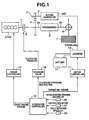
- FIG. 1 a driving force control apparatus for a hybrid vehicle according to a first embodiment of the present invention will be described.
- the hybrid vehicle includes transmission (power transmission means) 5 consisting of an automatic transmission or a continuously variable transmission.
- transmission (power transmission means) 5 consisting of an automatic transmission or a continuously variable transmission.
- To input shaft 5a of transmission 5 is connected by way of engine clutch 8 output shaft 1 of engine ENG, and to output shaft 5b of transmission 5 is connected by way of differential gear 6 driving wheels 7.
- To input shaft 5a of transmission 5 is connected by way of fixed reduction gears 3, 4 output shaft 2 of motor/generator MG.
- transmission 5 supplies power to driving wheels 7 after combining powers of engine ENG and motor/generator MG.
- transmission 5 and motor/generator MG are arranged in parallel with each other so as to constitute a hybrid transmission.
- the hybrid vehicle has two operation modes in which it is operated selectively depending upon an operating condition of engine clutch 8. Namely, when engine clutch 8 is released or disengaged, the vehicle is operated in an electric vehicle mode in which the vehicle is driven only by the power of motor/generator MG. When engine clutch 8 is engaged, the vehicle is operated in a hybrid mode in which the vehicle is driven by the powers of engine ENG and motor/generator MG.
- the driving force control apparatus includes integrated controller 10 for performing an integrated control of the overall energy, engine controller 12 for controlling engine ENG, motor controller 11 for controlling motor/generator MG of the power train described above, inverter 13 for supplying electricity to motor/generator MG, battery 14 for storing electric energy, and solenoid valve 16 for producing oil pressure to be supplied to engine clutch 8.
- Integrated controller 10 selects a driving mode that is capable of attaining a driving force required by a driver in accordance with accelerator opening degree AP inputted from accelerator opening degree sensor 20, vehicle speed VSP (proportional to an output shaft rotation speed) inputted from vehicle speed sensor 21, input rotation speed ⁇ in of transmission 5 inputted from input rotation speed sensor 22, etc. and give instructions on target MG torque and target engine torque to motor controller 11 and engine controller 12, respectively while supplying a driving signal to solenoid valve 16.
- FIG. 2A is shown a main routine of a driving force control process at the time of engagement of engine clutch.
- step S1 it is determined whether or not engine clutch engagement flag Mflag is 1. If engine clutch engagement flag Mflag is 1, engine clutch is in engagement and the control proceeds to an engagement control subroutine in step S2. If engine clutch engagement flag Mflag is 0, engine clutch is not in engagement and the control proceeds to an engagement determination subroutine in step S3.
- FIG. 2B is shown the engagement determination subroutine.
- step S21 vehicle speed VSP is calculated from output rotation speed ⁇ out of transmission 5 by using the following expression, and then the control proceeds to step S22.
- VSP Kv ⁇ ⁇ ⁇ out where Kv is a constant determined by a tire radius or a final gear ratio.
- step S22 target driving torque Tot is calculated from vehicle speed VSP and accelerator opening degree AP by using a map shown in FIG. 3 and the control proceeds to step S23 (target driving force setting or determining means).
- step S23 target transfer torque Tct0 of engine clutch 8 is set and the control proceeds to step S24.
- target transfer torque Tct0 can be given by a certain fixed value or by a value variable depending upon variations of target driving torque Tot and vehicle speed VSP.
- step S24 compensating or supplemental torque Tmc that is a motor torque value for supplementing a transfer torque of engine clutch 8 (compensating or supplemental torque calculating section or means) and the control proceeds to step S25.
- step S25 vehicle-driving motor torque Tmv is calculated (vehicle-driving motor toque calculating section or means) and the control proceeds to step S26.
- step S26 accelerator depression speed VAP is calculated and the control proceeds to step S27.
- accelerator depression speed VAP can be calculated based on a difference in the accelerator opening degree between the last control cycle and the present control cycle.
- step S27 accelerator opening degree Apm for determination of start of engagement of engine clutch 8 is set by the following process.
- step S28 it is determined whether or not accelerator opening degree AP is larger than accelerator engagement start determination opening degree APm. If accelerator opening degree AP is larger than engagement start determination accelerator opening degree APm, the control proceeds to step S29 to start engagement of engine clutch 8 (engagement instructing section or means). If smaller, the subroutine is ended.
- step S29 since engagement of engine clutch 8 is started, clutch engagement flag Mflag is set to 1, and the control proceeds to step S30.
- step S30 in order to make target driving torque Tom corresponding to engagement start determination accelerator opening degree APm after correction be corrected target driving torque in the process of engagement of engine clutch 8, corrected target driving torque Tom is calculated from engagement start determination accelerator opening degree APm and vehicle speed VSP by using the map shown in FIG. 3 (driving force correcting section or means) and the control proceeds to step S31.
- step S31 by making use of increase in the surplus of motor torque for compensation of engine clutch engagement torque, which is caused by decrease in the target driving torque in the process of engagement of engine clutch 8 in response to decrease in the accelerator opening degree for starting engagement of engine clutch 8, the target transfer torque of engine clutch 8 is increased.
- This Tct is determined as clutch transfer torque after correction.
- FIG. 2C shows a subroutine for clutch engagement control.
- step S41 an instruction on maximum motor torque Tmmax is given to motor/generator MG and the control proceeds to step S42.
- step S42 solenoid valve 16 is driven so as to realize clutch transfer torque Tct after correction that is set at the time of change of mode, and the control proceeds to step S43.
- step S43 it is determined whether or not the difference in the rotation speed between engine clutch plates (i.e., the difference between the engine rotation speed and the input rotation speed) is zero. If the answer is affirmative, the control proceeds to step S44. If the answer is negative, the routine is ended.
- step S44 it is determined that engagement of engine clutch 8 is completed in step S43 and the control goes to the hybrid mode.
- a driving force control at the time of engagement of engine clutch 8 is started in response to an instruction to change the electric vehicle mode to the hybrid mode.
- engine clutch 8 is not in the process of engagement but engine clutch engagement flag Mflag is 0.
- the control proceeds from step S1 in the flow chart of FIG. 2A to the subroutine in step S3.
- step S21 vehicle speed VSP is calculated in step S21.
- step S22 target driving torque Tot is calculated from vehicle speed VSP and accelerator opening degree AP.
- step S23 target transfer torque Tct0 of engine clutch 8 is set.
- step 24 compensating torque Tmc is calculated.
- step 25 vehicle-driving motor torque Tmv is calculated.
- step S26 accelerator depression speed VAP is calculated.
- step 27 accelerator opening degree APM for determination of start of engagement of engine clutch 8 is set.
- step S28 a comparison between detected accelerator opening degree AP and clutch engagement start determination accelerator opening degree APM is made. During AP ⁇ APm, the subroutine is repeated. Thereafter, if it comes the time when accelerator opening degree AP becomes larger than engagement start determination accelerator opening degree APm, the control proceeds to step S29 to start engagement of engine clutch 8. However, prior to start of engagement of engine clutch 8, engine clutch engagement flag Mflag is set to 1. Then, in step S30, it is calculated target driving torque Tom in the process of engagement of engine clutch 8, which corresponds to engagement start determination accelerator opening degree APm after correction and which can be realized by a motor toque equal to or smaller than the maximum motor torque. In step S31, compensating torque Tct after correction is calculated.
- step S29 engine clutch engagement flag Mflag is set to 1, the control proceeds from step S1 in the flow chart of FIG. 2A to engagement control subroutine in step S2.
- engagement control subroutine in FIG. 2C an instruction on maximum motor torque Tmmax is given to motor/generator MG in step S41.
- step S42 solenoid valve 16 is driven so as to realize clutch transfer torque Tct after correction.
- step S43 it is determined whether or not the rotational difference between the clutch plates is zero. The motor control in step S41 and the engine clutch engagement control in step S42 are repeated until the rotational difference between the clutch plates becomes zero. When the rotational difference becomes zero, the control proceeds to the hybrid mode control.
- step S27 since in the first embodiment and in the process (1) of step S27 the accelerator opening degree corresponding to the maximum driving torque Tomax is determined as the largest accelerator opening degree for determination of start of engagement of the engine clutch 8, the target driving torque before and in the process of engagement of the engine clutch 8 does not become larger than the maximum driving torque Tomax. Accordingly, the target driving torque in the process of engagement of the engine clutch 8 becomes equal to or smaller than the maximum driving torque Tomax, so that as shown by the driving force characteristic represented by the solid line in FIG. 7 , start of engagement of the engine clutch 8 does not cause such a drop or decrease of the driving force and a strange feel concerning acceleration as in the related art.
- step S27 since in step S27 the accelerator opening degree APm at which engagement of the engine clutch 8 is started is made smaller as the accelerator depression speed VAP becomes faster, the target driving torque Tomax during engagement of the engine clutch 8 becomes further smaller. Accordingly, the engine clutch torque can be compensated for more assuredly.
- the time at which engagement of the engine clutch 8 is started becomes earlier (t0 ⁇ t0' in FIG. 7 ).
- the time at which the engine ENG is started becomes earlier as compared with that in the related art, thus making shorter the time since the accelerator is depressed till a large driving force is produced thereby improving the responsiveness to acceleration requirement and making earlier the time at which the vehicle reaches a required speed.
- step S31 since the clutch transfer torque Tct after correction calculated in step S31 is larger as compared with that Tct0 before correction, the time necessary for engagement of the engine clutch 8 becomes shorter and the time at which the engine ENG is started becomes earlier (t2 ⁇ t2' in FIG. 7 ), thus making further shorter the time since the accelerator is depressed till the engine ENG produces a large driving force thereby improving the responsiveness to acceleration requirement and making earlier the time at which the vehicle reaches a required speed.
- the driving force control apparatus for a hybrid vehicle according to the first embodiment of the present invention can produce the following effects.
- FIG. 8 shows a driving force control apparatus for a hybrid vehicle according to a second embodiment of the present invention.
- a hybrid transmission includes a Ravigneaux type planetary gear unit and a motor/generator that is constituted by a composite current two phase motor MG'.
- the hybrid vehicle includes engine ENG, Ravigneaux type planetary gear mechanism 5' and composite current two-phase motor MG' which are arranged coaxially and in this order from the lefthand side in the figure.
- Ravigneaux type planetary gear mechanism 5' consists of single pinion planetary gear unit 52 and double-pinion planetary gear unit 51 which include pinion P2 in common.
- Single pinion planetary gear unit 52 is constructed to have sun gear S2 and ring gear R2 that are meshed with pinion P2.
- Double pinion planetary gear unit 51 includes sun gear S1, ring gear R1 and large-diameter pinion P1 in addition to common pinion P2.
- Large-diameter pinion P1 is meshed with three other gears, i.e., sun gear S1, ring gear R1 and gear R2, pinion P1 and pinion P2 as major elements and constitute a two-degree-freedom differential in which when the rotation speeds of two of the seven members are determined, the rotation speeds of other members are determined.
- Compound-current double-layer motor MG' includes inner rotor ri and annular outer rotor ro surrounding inner rotor ri.
- Inner and outer rotors ri, ro are arranged coaxially and rotatably supported on a rear axial end of the transmission case.
- Stator s made up of an annular coil is disposed coaxially in an annular space defined between inner rotor ri and outer rotor ro and fixedly connected to the transmission case.
- second motor/generator MG2 By stator s and inner rotor ri is constituted first motor/generator MG1.
- each of motor/generators MG1, MG2 When compound multiphase alternating current is supplied to each of first and second motor/generators MG1, MG2, each of motor/generators MG1, MG2 functions as an electric motor which outputs a rotational force having a rotational direction corresponding to a current direction and a rotation speed corresponding to a current strength of the supplied current.
- each of motor/generators MG1, MG2 When no compound multiphase alternating current is supplied to each of first and second motor/generators MG1, MG2, each of motor/generators MG1, MG2 functions as a generator which outputs an electric power corresponding to rotation thereof caused by an external force.
- first motor/generator MG1 (specifically, inner rotor ri) is connected to sun gear S1 of double pinion planetary gearset 51 and first motor/generator MG1 (specifically, outer rotor ro) is connected to sun gear S2 of single pinion planetary gearset 52.
- the driving force control apparatus of the first embodiment can be used at the time of engagement of engine clutch 8 when the hybrid transmission is in the fixed transmission ratio mode and can produce substantially the same effect as in the hybrid transmission of the first embodiment.
- the hybrid transmission for a hybrid vehicle to which the driving force control apparatus of the present invention is applied is not limited to the structure having been described with respect to the first and second embodiments but the present invention can be applied to a hybrid vehicle having a power transmission mechanism that outputs power by adding the power of a motor/generator to the power of an engine and an engine clutch that selectively engaging the engine with the power transmission mechanism.
- the scope of the invention is defined with reference to the following claims.
Landscapes
- Engineering & Computer Science (AREA)
- Chemical & Material Sciences (AREA)
- Combustion & Propulsion (AREA)
- Transportation (AREA)
- Mechanical Engineering (AREA)
- Automation & Control Theory (AREA)
- Hybrid Electric Vehicles (AREA)
- Electric Propulsion And Braking For Vehicles (AREA)
- Control Of Driving Devices And Active Controlling Of Vehicle (AREA)
Claims (9)
- Antriebskraft- Steuerungsvorrichtung für ein Hybridfahrzeug mit einer Brennkraftmaschine (ENG), einem Motor / Generator (MG; MG'), einem Getriebe (5; 5') zum Übertragen von Leistungen der Brennkraftmaschine (1) und des Motor / Generators (MG; MG') zum Antrieben von Rädern (7) des Fahrzeuges, und einer Motorkupplung (8), angeordnet zwischen der Brennkraftmaschine (ENG) und dem Getriebe (5; 5'), wobei die Antriebskraft- Steuerungsvorrichtung aufweist:einen Ziel- Antriebsdrehmoment- Festlegungsabschnitt, der ein Ziel- Antriebsdrehmoment (Tot) auf der Grundlage eines Beschleunigeröffnungsgrades (AP) und einer Fahrzeuggeschwindigkeit (VSP) festlegt;einen Kompensationsdrehmoment- Berechnungsabschnitt, der ein Kompensationsdrehmoment (Tmc) zum Kompensieren des Eingriffs der Motorkupplung (8) berechnet;einen Fahrzeugantriebs- Motordrehmoment- Berechnungsabschnitt, der ein Fahrzeugantriebs- Motordrehmoment (Tmv) in Übereinstimmung mit dem Kompensationsdrehmoment (Tmc) berechnet,einen Eingriffs- Anweisungsabschnitt, der die Motorkupplung (8) anweist, in Eingriff zu kommen,dadurch gekennzeichnet, dass
der Kompensationsdrehmoment- Berechnungsabschnitt das Kompensationsdrehmoment (Tmc) zum Kompensieren der Verminderung in einer Fahrzeugantriebskraft berechnet, die sonst zu der Zeit den Eingriff der Motorkupplung (8) verursacht wird, und der Fahrzeugantriebs- Motordrehmoment- Korfrekturabschnitt das Fahrzeugantriebs- Motordrehmoment (Tmv) durch Subtrahieren des Kompensationsdrehmomentes (Tmc) von einem maximalen Motordrehmoment (Tmmax) des Motor / Generators (MG; MG') berechnet, wobei ein Antriebskraft-Berechnungsabschnitt vorgesehen ist, um das Ziel- Antriebsdrehmoment (Tot) auf ein korrigiertes Ziel- Antriebsdrehmoment (Tom) zu korrigieren, das durch das Fahrzeugantriebs- Motordrehmoment (Tmv) realisiert werden kann, nachdem der Eingriff der Motorkupplung (8) gestartet wird und bevor der Eingriff der Motorkupplung (8) abgeschlossen ist. - Antriebskraft- Steuerungsvorrichtung nach Anspruch 1, dadurch gekennzeichnet, dass der Eingriffs- Anweisungsabschnitt konfiguriert ist, die Motorkupplung (8) anzuweisen, den Eingriff zu starten, wenn ein Beschleunigeröffnungsgrad (AP) gleich zu oder größer als ein Eingriffsstartfestlegungs- Beschleunigeröffnungsgrad (APm) ist, der dem korrigierten Ziel- Antriebsdrehmoment (Tom) entspricht.
- Antriebskraft- Steuerungsvorrichtung nach Anspruch 2, dadurch gekennzeichnet, dass der Eingriffs- Anweisungsabschnitt konfiguriert ist, anzunehmen, dass ein endgültiger Beschleunigeröffnungsgrad (AP) und das Ziel- Antriebsdrehmoment (Tot) größer werden, wenn eine Beschleuniger- Niederdrückgeschwindigkeit (VAP) höher wird, und den Eingriffsstart- Festlegungs- Beschleunigeröffnungsgrad (APm) kleiner festlegen, wenn die Beschleuniger- Niederdrückgeschwindigkeit (VAP) höher wird.
- Antriebskraft- Steuerungsvorrichtung nach Anspruch 3, dadurch gekennzeichnet, dass der Eingriffs- Anweisungsabschnitt konfiguriert ist, eine Drehmomentübertragungskapazität der Motorkupplung (8) zu der Zeit des Eingriffs der Motorkupplung (8) zu erhöhen, wenn die Beschleuniger- Niederdrückgeschwindigkeit (VAP) höher wird.
- Antriebskraft- Steuerungsvorrichtung nach einem der Ansprüche 1 bis 4, dadurch gekennzeichnet, dass das Hybridfahrzeug zumindest einen Motor / Generator (MG; MG') hat und das Getriebe (5; 5') zum Übertragen von Leistung auf eine Ausgangswelle (5b), verbunden mit den Antriebsrädern (7) des Fahrzeuges, nach dem Kombinieren der Leistungen der Brennkraftmaschine und des Motor / Generators (MG; MG') vorgesehen ist,
wobei die Motorkupplung (8) vorgesehen ist zwischen der Brennkraftmaschine (ENG) und dem Getriebe (5; 5') zum Steuern der Leistungsübertragung zwischen der Brennkraftmaschine (ENG) und dem Getriebe (5; 5'), in dem ein Betriebsmodus des Fahrzeuges geschaltet wird zwischen einem Hybridmodus, in dem das Fahrzeug durch die Leistungen der Brennkraftmaschine (ENG) und des Motor / Generators (MG; MG') angetrieben wird, und einem elektrischen Fahrzeugmodus, in dem das Fahrzeug nur durch die Leistung des Motor / Generators (MG; MG') angetrieben wird, wobei der Hybridmodus durch den Eingriff der Motorkupplung (8) erhalten wird und der elektrische Fahrzeugmodus durch das Lösen der Motorkupplung (8) erhalten wird. - Antriebskraft- Steuerungsverfahren für ein Hybridfahrzeug mit einer Brennkraftmaschine (ENG), einem Motor / Generator (MG; MG'), einem Getriebe (5; 5') zum Übertragen von Leistungen der Brennkraftmaschine (ENG) und des Motor / Generators (MG; MG'), um Räder (7) des Fahrzeuges anzutreiben, und einer Motorkupplung (8), angeordnet zwischen der Brennkraftmaschine (ENG) und dem Getriebe (5; 5'), wobei das Antriebskraft- Steuerungsverfahren aufweist:Festlegen eines Ziel- Antriebsdrehmomentes (Tot) auf der Grundlage eines Beschleunigeröffnungsgrades (AP) und einer Fahrzeuggeschwindigkeit (VSP); Berechnen eines Kompensationsdrehmomentes (Tmc) zum Kompensieren des Eingriffs der Motorkupplung (8);Berechnen des Fahrzeugantriebs- Motordrehmomentes (Tmv) in Übereinstimmung mit dem Kompensationsdrehmoment (Tmc),Anweisen der Motorkupplung (8), den Eingriff zu starten,
gekennzeichnet durchBerechnen des Kompensationsdrehmomentes (Tmc) zum Kompensieren einer Verminderung in der Fahrzeugantriebskraft, die sonst zu der Zeit den Eingriff der Motorkupplung (8) verursacht würde, undBerechnen des Fahrzeugantriebs- Motordrehmomentes (Tmv) durch Subtrahieren des Kompensationsdrehmomentes (Tmc) von einem maximalen Motordrehmoment (Tmmax) des Motor / Generators (MG; MG'),Korrigieren des Ziel- Antriebsdrehmomentes (Tot) auf ein korrigiertes Ziel- Antriebsdrehmoment (Tom), das durch das Fahrzeugantriebs- Motordrehmoment (Tmv) realisiert werden kann, nachdem der Eingriff der Motorkupplung (8) gestartet ist und bevor der Eingriff der Motorkupplung (8) abgeschlossen ist. - Antriebskraft- Steuerungsverfahren nach Anspruch 6, gekennzeichnet durch Anweisen der Motorkupplung (8), den Eingriff zu starten, wenn ein Beschleunigeröffnungsgrad (AP) gleich zu oder größer als ein Eingriffsstartfestlegungs- Beschleunigeröffnungsgrad (APm) wird, der dem korrigierten Ziel- Antriebsdrehmoment (Tom) entspricht.
- Antriebskraft- Steuerungsverfahren nach Anspruch 7, gekennzeichnet durch Annehmen, dass ein endgültiger Beschleunigeröffnungsgrad (AP) und das Ziel-Antriebsdrehmoment (Tot) größer werden, wenn eine Beschleuniger- Niederdrückgeschwindigkeit (VAP) höher wird und einen Beschleunigeröffnungsgrad (APm) kleiner festzulegen in Abhängigkeit von dem, der Eingriff der Motorkupplung (8) gestartet wird, wenn die Beschleuniger- Niederdrückgeschwindigkeit (VAP) höher wird.
- Antriebskraft- Steuerungsverfahren nach Anspruch 8, gekennzeichnet durch Erhöhen einer Drehmomentübertragungskapazität der Motorkupplung (8) zu der Zeit des Eingriffs der Motorkupplung (8), wenn die Beschleuniger- Niederdrückgeschwindigkeit (VAP) höher wird.
Applications Claiming Priority (2)
| Application Number | Priority Date | Filing Date | Title |
|---|---|---|---|
| JP2003378530A JP2005138743A (ja) | 2003-11-07 | 2003-11-07 | ハイブリッド車両の駆動力制御装置 |
| JP2003378530 | 2003-11-07 |
Publications (3)
| Publication Number | Publication Date |
|---|---|
| EP1529672A2 EP1529672A2 (de) | 2005-05-11 |
| EP1529672A3 EP1529672A3 (de) | 2006-12-13 |
| EP1529672B1 true EP1529672B1 (de) | 2009-10-14 |
Family
ID=34431351
Family Applications (1)
| Application Number | Title | Priority Date | Filing Date |
|---|---|---|---|
| EP04026075A Expired - Lifetime EP1529672B1 (de) | 2003-11-07 | 2004-11-03 | Antriebskraftsteuerung und Vorrichtung für ein Hybridfahrzeug |
Country Status (5)
| Country | Link |
|---|---|
| US (1) | US7179195B2 (de) |
| EP (1) | EP1529672B1 (de) |
| JP (1) | JP2005138743A (de) |
| CN (1) | CN100339262C (de) |
| DE (1) | DE602004023578D1 (de) |
Families Citing this family (75)
| Publication number | Priority date | Publication date | Assignee | Title |
|---|---|---|---|---|
| JP3843966B2 (ja) * | 2003-06-05 | 2006-11-08 | アイシン・エィ・ダブリュ株式会社 | ハイブリッド型車両駆動制御装置、ハイブリッド型車両駆動制御方法及びそのプログラム |
| EP1619063B1 (de) * | 2004-07-21 | 2009-10-14 | Nissan Motor Company, Limited | Verfahren und Vorrichtung zum Steuern des Drehmoments eines Elektromotors für ein Kraftfahrzeug |
| JP2007112258A (ja) * | 2005-10-19 | 2007-05-10 | Nissan Motor Co Ltd | ハイブリッド駆動装置のエンジン始動制御装置 |
| JP4462170B2 (ja) | 2005-11-07 | 2010-05-12 | 日産自動車株式会社 | ハイブリッド車両のエンジン始動制御装置 |
| DE102005062869A1 (de) * | 2005-12-29 | 2007-07-05 | Robert Bosch Gmbh | Verfahren zur Vereinfachung der Momentenüberwachung, insbesondere bei Hybridantrieben |
| JP4696918B2 (ja) * | 2006-01-10 | 2011-06-08 | トヨタ自動車株式会社 | 車両の制御装置 |
| JP4567619B2 (ja) * | 2006-03-01 | 2010-10-20 | 三菱ふそうトラック・バス株式会社 | ハイブリッド電気自動車の制御装置 |
| JP4637770B2 (ja) * | 2006-03-01 | 2011-02-23 | 三菱ふそうトラック・バス株式会社 | ハイブリッド電気自動車の制御装置 |
| WO2007102762A1 (en) | 2006-03-09 | 2007-09-13 | Volvo Technology Corporation | Hybrid powertrain |
| JP2007261442A (ja) * | 2006-03-29 | 2007-10-11 | Nissan Motor Co Ltd | ハイブリッド車両の運転モード遷移制御装置 |
| JP2012131497A (ja) * | 2006-05-24 | 2012-07-12 | Nissan Motor Co Ltd | ハイブリッド車両のエンジン始動制御装置及びハイブリッド車両のエンジン始動制御方法 |
| JP5371200B2 (ja) | 2006-05-24 | 2013-12-18 | 日産自動車株式会社 | ハイブリッド車両のエンジン始動制御装置及びハイブリッド車両のエンジン始動制御方法。 |
| TW200829461A (en) * | 2006-07-25 | 2008-07-16 | Yamaha Motor Co Ltd | Hybrid motorcycle |
| JP4755039B2 (ja) | 2006-07-25 | 2011-08-24 | ヤマハ発動機株式会社 | ハイブリッド式自動二輪車 |
| JP4797878B2 (ja) * | 2006-08-15 | 2011-10-19 | 日産自動車株式会社 | ハイブリッド車両の電気走行制御装置 |
| JP4317861B2 (ja) * | 2006-08-31 | 2009-08-19 | 株式会社東海理化電機製作所 | ハイブリッド車の走行モード設定装置 |
| US9389008B2 (en) * | 2006-10-23 | 2016-07-12 | Ralph Muscatell | Solar energy air conditioning system with storage capability |
| DE102007010770A1 (de) * | 2007-03-06 | 2008-09-11 | Robert Bosch Gmbh | Verfahren und Steuervorrichtung zum Durchführen eines Startens eines Verbrennungsmotors in einem Hybridfahrzeug |
| JP4834519B2 (ja) * | 2006-11-10 | 2011-12-14 | アイシン精機株式会社 | 車両の駆動源制御装置 |
| JP4516577B2 (ja) * | 2007-02-09 | 2010-08-04 | 日立オートモティブシステムズ株式会社 | 車両駆動装置 |
| US8204659B2 (en) * | 2007-03-12 | 2012-06-19 | Nissan Motor Co., Ltd. | Engine start control system for hybrid vehicle |
| US7918763B2 (en) * | 2007-04-12 | 2011-04-05 | Ford Global Technologies, Llc | Control strategy for multi-mode vehicle propulsion system |
| US7628728B2 (en) * | 2007-06-07 | 2009-12-08 | Ford Global Technologies, Llc | Launch control of a hybrid electric vehicle |
| US8170762B2 (en) * | 2007-10-29 | 2012-05-01 | GM Global Technology Operations LLC | Method and apparatus to control operation of a hydraulic pump for an electro-mechanical transmission |
| US7699129B2 (en) * | 2007-10-31 | 2010-04-20 | Ford Global Technologies, Llc | Method and system for alerting a driver that a motive power system is about to be activated |
| US8070647B2 (en) * | 2007-11-05 | 2011-12-06 | GM Global Technology Operations LLC | Method and apparatus for adapting engine operation in a hybrid powertrain system for active driveline damping |
| DE102007047824A1 (de) * | 2007-11-20 | 2009-05-28 | Zf Friedrichshafen Ag | Verfahren zur Übergabe der Sollwerte und/oder der Sollantriebsstrangzustände |
| FR2923792B1 (fr) | 2007-11-21 | 2010-03-12 | Peugeot Citroen Automobiles Sa | Procede de pilotage du passage d'un mode electrique a un mode mixte electrique et thermique d'un groupe motopropulseur hybride et groupe motopropulseur hybride |
| CN101878142B (zh) * | 2007-11-30 | 2014-03-12 | 博世株式会社 | 混合动力系统控制方法 |
| KR100992781B1 (ko) | 2007-12-13 | 2010-11-05 | 기아자동차주식회사 | 하이브리드 차량의 클러치 결합제어를 위한 시스템과 그방법 |
| EP2271531B2 (de) * | 2008-04-28 | 2018-11-07 | Mack Trucks, Inc. | Antriebsstrang mit eingangswelle und motordrehzahlsynchronisierung und verfahren zum schalten von gängen in einem antriebsstrang |
| DE102008043159A1 (de) * | 2008-10-24 | 2010-04-29 | Robert Bosch Gmbh | Verfahren und Vorrichtung zum Anfahren eines Hybridfahrzeuges |
| KR101028014B1 (ko) | 2008-10-31 | 2011-04-13 | 현대자동차일본기술연구소 | 하이브리드 차량의 클러치 전달토크 제어 방법 |
| WO2010052768A1 (ja) * | 2008-11-05 | 2010-05-14 | トヨタ自動車株式会社 | ハイブリッド車両の制御装置 |
| TW201020137A (en) * | 2008-11-28 | 2010-06-01 | Tian Rung Internat Dev Co Ltd | Device and method for assisting engine to generate power |
| CN101954853B (zh) * | 2009-07-17 | 2015-03-04 | 甘国华 | 一种节能环保混合动力汽车 |
| CN101973267B (zh) * | 2010-09-17 | 2013-02-13 | 清华大学 | 混合动力电动汽车牵引力分层控制方法 |
| JP2012086742A (ja) * | 2010-10-21 | 2012-05-10 | Hino Motors Ltd | 走行モード制御装置、ハイブリッド自動車、および走行モード制御方法、並びにプログラム |
| JP5832736B2 (ja) * | 2010-10-26 | 2015-12-16 | 日産自動車株式会社 | ハイブリッド車両のエンジン始動制御装置 |
| JP5422544B2 (ja) * | 2010-12-17 | 2014-02-19 | アイシン・エーアイ株式会社 | 車両の動力伝達制御装置 |
| CN103339002A (zh) * | 2011-02-04 | 2013-10-02 | 铃木株式会社 | 混合动力车辆 |
| JP5741029B2 (ja) * | 2011-02-04 | 2015-07-01 | 日産自動車株式会社 | 電動車両の踏み込みダウンシフト制御装置 |
| KR101241224B1 (ko) * | 2011-08-11 | 2013-03-13 | 기아자동차주식회사 | 하이브리드 자동차의 시동모터 제어방법 |
| JP5854052B2 (ja) * | 2011-10-21 | 2016-02-09 | トヨタ自動車株式会社 | 車両の制御装置 |
| KR101339233B1 (ko) * | 2011-12-01 | 2013-12-09 | 기아자동차 주식회사 | 하이브리드 차량의 엔진 정지상태 판단 시스템 및 방법 |
| WO2013137080A1 (ja) * | 2012-03-13 | 2013-09-19 | 日産自動車株式会社 | ハイブリッド車両の制御装置 |
| US9096208B2 (en) * | 2012-05-07 | 2015-08-04 | Ford Global Technologies, Llc | Controlling a traction motor during engine pull-up in a vehicle |
| JP6019732B2 (ja) * | 2012-05-15 | 2016-11-02 | 三菱自動車工業株式会社 | ハイブリッド自動車の制御装置 |
| CN104853952B (zh) * | 2012-12-12 | 2016-12-14 | 日产自动车株式会社 | 车辆的驱动扭矩控制装置 |
| CN102975713A (zh) * | 2012-12-14 | 2013-03-20 | 清华大学 | 基于模型预测控制的混合动力汽车控制方法 |
| JP5939309B2 (ja) * | 2012-12-26 | 2016-06-22 | トヨタ自動車株式会社 | ハイブリッド車両の制御装置 |
| EP2969686B1 (de) * | 2013-03-13 | 2022-05-11 | Allison Transmission, Inc. | System und verfahren zur erkennung von fahrzeugkupplungs-berührungspunkten |
| WO2014174909A1 (ja) * | 2013-04-23 | 2014-10-30 | 日産自動車株式会社 | ハイブリッド車両の制御装置 |
| BR112015027604B1 (pt) * | 2013-04-30 | 2021-11-03 | Toyota Jidosha Kabushiki Kaisha | Dispositivo de direção para veículo híbrido |
| JP6303422B2 (ja) * | 2013-11-14 | 2018-04-04 | 日産自動車株式会社 | ハイブリッド車両の制御装置 |
| JP6183169B2 (ja) * | 2013-11-14 | 2017-08-23 | 日産自動車株式会社 | ハイブリッド車両の制御装置 |
| CN103818375B (zh) * | 2014-03-05 | 2016-03-30 | 东风襄阳旅行车有限公司 | 单轴并联式混合动力汽车发动机转矩估算校正方法 |
| US9238460B1 (en) | 2014-07-23 | 2016-01-19 | Toyota Motor Corporation | Systems for managing downshifts in hybrid-electric vehicles |
| US9810273B2 (en) * | 2014-07-30 | 2017-11-07 | Ford Global Technologies, Llc | Methods and system for applying a driveline disconnect clutch |
| JP6399038B2 (ja) * | 2016-05-18 | 2018-10-03 | トヨタ自動車株式会社 | ハイブリッド自動車 |
| WO2018078803A1 (ja) * | 2016-10-28 | 2018-05-03 | 日産自動車株式会社 | ハイブリッド車両の制御方法と制御装置 |
| KR102383231B1 (ko) * | 2016-12-15 | 2022-04-05 | 현대자동차 주식회사 | 하이브리드 차량의 엔진 클러치 접합점 학습 방법 및 그 학습 장치 |
| US11110908B2 (en) | 2017-04-17 | 2021-09-07 | Hyundai Motor Company | Hybrid vehicle and method of controlling mode transition thereof |
| JP2019002309A (ja) * | 2017-06-14 | 2019-01-10 | スズキ株式会社 | 車両の制御装置 |
| CN109204295B (zh) * | 2017-06-30 | 2021-07-20 | 比亚迪股份有限公司 | 混合动力车辆及其发动机启动控制方法和系统 |
| US11427180B2 (en) * | 2017-12-15 | 2022-08-30 | Nissan Motor Co., Ltd. | Control method and control device for hybrid vehicle |
| CN110949111B (zh) * | 2018-09-27 | 2023-10-20 | 西安交通大学 | 双转子电机与拉维娜式行星轮系串联式汽车混合动力系统 |
| CN111086503A (zh) * | 2018-10-23 | 2020-05-01 | 上海汽车变速器有限公司 | 用于双离合器混动变速器的启动控制方法 |
| CN111791717B (zh) * | 2019-04-08 | 2022-05-17 | 宇通客车股份有限公司 | 一种多模电驱动系统及车辆 |
| JP7230715B2 (ja) * | 2019-07-09 | 2023-03-01 | トヨタ自動車株式会社 | ハイブリッド車両の制御装置 |
| FR3104105B1 (fr) * | 2019-12-05 | 2021-11-19 | Psa Automobiles Sa | Procede de compensation d'erreurs de realisation de couple d'un moteur thermique dans une chaine de traction hybride |
| CN113085567A (zh) * | 2019-12-23 | 2021-07-09 | 博世汽车部件(苏州)有限公司 | 驱动扭矩控制方法和系统、电动骑行车辆及可读存储介质 |
| JP2021138309A (ja) * | 2020-03-06 | 2021-09-16 | 本田技研工業株式会社 | 車両 |
| CN112706754B (zh) * | 2021-01-26 | 2022-07-29 | 上汽通用五菱汽车股份有限公司 | 混合动力车辆及发动机启动方法和计算机可读存储介质 |
| CN115257752B (zh) * | 2022-07-29 | 2024-05-03 | 重庆长安汽车股份有限公司 | 一种混合动力汽车起步控制方法、系统及汽车 |
Family Cites Families (17)
| Publication number | Priority date | Publication date | Assignee | Title |
|---|---|---|---|---|
| JP3644207B2 (ja) * | 1997-08-19 | 2005-04-27 | 日産自動車株式会社 | ハイブリッド車両の変速制御装置 |
| JP3775012B2 (ja) * | 1997-08-29 | 2006-05-17 | アイシン・エィ・ダブリュ株式会社 | 車両用ハイブリッド駆動装置 |
| JP3368816B2 (ja) * | 1997-12-05 | 2003-01-20 | 日産自動車株式会社 | ハイブリッド車の制御装置 |
| JP3451935B2 (ja) * | 1998-06-03 | 2003-09-29 | 日産自動車株式会社 | ハイブリッド車両の駆動力制御装置 |
| JP3409701B2 (ja) * | 1998-07-03 | 2003-05-26 | 日産自動車株式会社 | ハイブリッド車両の制御装置 |
| JP3541875B2 (ja) * | 1999-01-19 | 2004-07-14 | 三菱自動車工業株式会社 | ハイブリッド車のエンジン始動装置 |
| JP2000224714A (ja) * | 1999-02-03 | 2000-08-11 | Mitsubishi Motors Corp | 電動機付車両 |
| JP2000343965A (ja) * | 1999-06-08 | 2000-12-12 | Nissan Diesel Motor Co Ltd | ハイブリッド車両 |
| JP2001219765A (ja) | 2000-02-10 | 2001-08-14 | Isuzu Motors Ltd | ハイブリッド車両駆動制御方法 |
| US6364807B1 (en) * | 2000-06-30 | 2002-04-02 | Ford Global Technologies, Inc. | Control strategy for a hybrid powertrain for an automotive vehicle |
| GB2370130B (en) * | 2000-10-11 | 2004-10-06 | Ford Motor Co | A control system for a hybrid electric vehicle |
| KR20040030430A (ko) * | 2000-10-16 | 2004-04-09 | 닛산 디젤 고교 가부시끼가이샤 | 차량의 하이브리드 시스템 |
| JP3573202B2 (ja) * | 2000-11-06 | 2004-10-06 | 三菱自動車工業株式会社 | ハイブリッド車両のトルク制御装置 |
| JP3632634B2 (ja) * | 2001-07-18 | 2005-03-23 | 日産自動車株式会社 | ハイブリッド車両の制御装置 |
| JP2003200758A (ja) * | 2001-12-28 | 2003-07-15 | Honda Motor Co Ltd | ハイブリッド車両の駆動制御装置 |
| JP3901041B2 (ja) * | 2002-07-10 | 2007-04-04 | 日産自動車株式会社 | ハイブリッド車両のトルク制御装置 |
| US7261671B2 (en) * | 2003-09-10 | 2007-08-28 | Ford Global Technologies, Llc | Hybrid vehicle powertrain with a multiple-ratio power transmission mechanism |
-
2003
- 2003-11-07 JP JP2003378530A patent/JP2005138743A/ja not_active Ceased
-
2004
- 2004-11-03 EP EP04026075A patent/EP1529672B1/de not_active Expired - Lifetime
- 2004-11-03 DE DE602004023578T patent/DE602004023578D1/de not_active Expired - Lifetime
- 2004-11-05 CN CNB2004100922481A patent/CN100339262C/zh not_active Expired - Fee Related
- 2004-11-08 US US10/982,883 patent/US7179195B2/en not_active Expired - Fee Related
Also Published As
| Publication number | Publication date |
|---|---|
| EP1529672A2 (de) | 2005-05-11 |
| CN1613682A (zh) | 2005-05-11 |
| JP2005138743A (ja) | 2005-06-02 |
| US7179195B2 (en) | 2007-02-20 |
| CN100339262C (zh) | 2007-09-26 |
| DE602004023578D1 (de) | 2009-11-26 |
| EP1529672A3 (de) | 2006-12-13 |
| US20050101433A1 (en) | 2005-05-12 |
Similar Documents
| Publication | Publication Date | Title |
|---|---|---|
| EP1529672B1 (de) | Antriebskraftsteuerung und Vorrichtung für ein Hybridfahrzeug | |
| US7734401B2 (en) | Shift control system of a hybrid transmission with a motor torque correction | |
| JP4548543B2 (ja) | ハイブリッド車両の駆動トルク制御装置 | |
| EP1564056B1 (de) | Schaltmodussteuerung für ein Hybridgetriebe | |
| JP3641244B2 (ja) | ハイブリッド変速機の変速制御装置 | |
| EP1544019B1 (de) | Vorrichtung und Verfahren zum Steuern der Umschaltung des Betriebsmodus | |
| EP1491427B1 (de) | Steuerung und Verfahren zum Wechseln der Betriebsart für ein Hybridfahrzeug | |
| US7609011B2 (en) | Electric force transmission device | |
| US7256510B2 (en) | Hybrid electro-mechanical transmission with single motor/generator and method of control | |
| EP0937600B1 (de) | Hybridantriebssystem und hiermit versehenes Fahrzeug | |
| US20060289212A1 (en) | Hybrid vehicle control operation | |
| US20050082992A1 (en) | Drive train for hybrid electric vehicle | |
| US20100018788A1 (en) | Power output apparatus, vehicle equipped with power output apparatus, and control method of power output apparatus | |
| US11208112B2 (en) | Drive force control system for vehicle | |
| US20080093141A1 (en) | Vehicle and control method of vehicle | |
| JP4325732B2 (ja) | ハイブリッド型の車両用駆動システム | |
| US10894537B2 (en) | Speed change control system for vehicle | |
| US10969011B2 (en) | Method and system for disengaging parking pawl in hybrid transmission | |
| JP4094591B2 (ja) | ハイブリッド車両の駆動装置 | |
| JP4258513B2 (ja) | 駆動装置の制御装置 | |
| CN106080588A (zh) | 车辆的控制装置 | |
| JP3786021B2 (ja) | ハイブリッド車両の制御装置 | |
| JP4462219B2 (ja) | ハイブリッド車およびその制御方法 | |
| JP3941776B2 (ja) | ハイブリッド車両の制御装置 | |
| JP2007045284A (ja) | ハイブリッド変速機 |
Legal Events
| Date | Code | Title | Description |
|---|---|---|---|
| PUAI | Public reference made under article 153(3) epc to a published international application that has entered the european phase |
Free format text: ORIGINAL CODE: 0009012 |
|
| 17P | Request for examination filed |
Effective date: 20041103 |
|
| AK | Designated contracting states |
Kind code of ref document: A2 Designated state(s): AT BE BG CH CY CZ DE DK EE ES FI FR GB GR HU IE IS IT LI LU MC NL PL PT RO SE SI SK TR |
|
| AX | Request for extension of the european patent |
Extension state: AL HR LT LV MK YU |
|
| PUAL | Search report despatched |
Free format text: ORIGINAL CODE: 0009013 |
|
| AK | Designated contracting states |
Kind code of ref document: A3 Designated state(s): AT BE BG CH CY CZ DE DK EE ES FI FR GB GR HU IE IS IT LI LU MC NL PL PT RO SE SI SK TR |
|
| AX | Request for extension of the european patent |
Extension state: AL HR LT LV MK YU |
|
| 17Q | First examination report despatched |
Effective date: 20070703 |
|
| AKX | Designation fees paid |
Designated state(s): DE FR GB |
|
| GRAP | Despatch of communication of intention to grant a patent |
Free format text: ORIGINAL CODE: EPIDOSNIGR1 |
|
| RIC1 | Information provided on ipc code assigned before grant |
Ipc: B60K 6/445 20071001ALI20090407BHEP Ipc: B60K 6/365 20071001AFI20090407BHEP Ipc: B60W 20/00 20060101ALI20090407BHEP Ipc: B60W 10/08 20060101ALI20090407BHEP Ipc: B60W 10/06 20060101ALI20090407BHEP Ipc: B60K 6/48 20071001ALI20090407BHEP |
|
| GRAS | Grant fee paid |
Free format text: ORIGINAL CODE: EPIDOSNIGR3 |
|
| GRAA | (expected) grant |
Free format text: ORIGINAL CODE: 0009210 |
|
| AK | Designated contracting states |
Kind code of ref document: B1 Designated state(s): DE FR GB |
|
| REG | Reference to a national code |
Ref country code: GB Ref legal event code: FG4D |
|
| REF | Corresponds to: |
Ref document number: 602004023578 Country of ref document: DE Date of ref document: 20091126 Kind code of ref document: P |
|
| PLBE | No opposition filed within time limit |
Free format text: ORIGINAL CODE: 0009261 |
|
| STAA | Information on the status of an ep patent application or granted ep patent |
Free format text: STATUS: NO OPPOSITION FILED WITHIN TIME LIMIT |
|
| 26N | No opposition filed |
Effective date: 20100715 |
|
| PGFP | Annual fee paid to national office [announced via postgrant information from national office to epo] |
Ref country code: DE Payment date: 20141029 Year of fee payment: 11 Ref country code: GB Payment date: 20141029 Year of fee payment: 11 Ref country code: FR Payment date: 20141110 Year of fee payment: 11 |
|
| REG | Reference to a national code |
Ref country code: DE Ref legal event code: R119 Ref document number: 602004023578 Country of ref document: DE |
|
| GBPC | Gb: european patent ceased through non-payment of renewal fee |
Effective date: 20151103 |
|
| REG | Reference to a national code |
Ref country code: FR Ref legal event code: ST Effective date: 20160729 |
|
| PG25 | Lapsed in a contracting state [announced via postgrant information from national office to epo] |
Ref country code: GB Free format text: LAPSE BECAUSE OF NON-PAYMENT OF DUE FEES Effective date: 20151103 Ref country code: DE Free format text: LAPSE BECAUSE OF NON-PAYMENT OF DUE FEES Effective date: 20160601 |
|
| PG25 | Lapsed in a contracting state [announced via postgrant information from national office to epo] |
Ref country code: FR Free format text: LAPSE BECAUSE OF NON-PAYMENT OF DUE FEES Effective date: 20151130 |