EP1510482B1 - Laser machining apparatus and laser machining method - Google Patents
Laser machining apparatus and laser machining method Download PDFInfo
- Publication number
- EP1510482B1 EP1510482B1 EP04254950A EP04254950A EP1510482B1 EP 1510482 B1 EP1510482 B1 EP 1510482B1 EP 04254950 A EP04254950 A EP 04254950A EP 04254950 A EP04254950 A EP 04254950A EP 1510482 B1 EP1510482 B1 EP 1510482B1
- Authority
- EP
- European Patent Office
- Prior art keywords
- work
- retaining
- workpiece
- workpieces
- stocker
- Prior art date
- Legal status (The legal status is an assumption and is not a legal conclusion. Google has not performed a legal analysis and makes no representation as to the accuracy of the status listed.)
- Expired - Lifetime
Links
- 238000003754 machining Methods 0.000 title claims description 69
- 238000000034 method Methods 0.000 title claims description 54
- 238000007599 discharging Methods 0.000 claims description 70
- 230000000717 retained effect Effects 0.000 claims description 43
- 230000001678 irradiating effect Effects 0.000 claims description 18
- 238000001179 sorption measurement Methods 0.000 description 15
- 230000003287 optical effect Effects 0.000 description 12
- 238000009434 installation Methods 0.000 description 4
- 230000000630 rising effect Effects 0.000 description 3
- 238000010521 absorption reaction Methods 0.000 description 1
- 230000008602 contraction Effects 0.000 description 1
- 239000011347 resin Substances 0.000 description 1
- 229920005989 resin Polymers 0.000 description 1
Images


Classifications
-
- B—PERFORMING OPERATIONS; TRANSPORTING
- B65—CONVEYING; PACKING; STORING; HANDLING THIN OR FILAMENTARY MATERIAL
- B65H—HANDLING THIN OR FILAMENTARY MATERIAL, e.g. SHEETS, WEBS, CABLES
- B65H3/00—Separating articles from piles
- B65H3/08—Separating articles from piles using pneumatic force
- B65H3/0808—Suction grippers
- B65H3/0816—Suction grippers separating from the top of pile
-
- B—PERFORMING OPERATIONS; TRANSPORTING
- B23—MACHINE TOOLS; METAL-WORKING NOT OTHERWISE PROVIDED FOR
- B23K—SOLDERING OR UNSOLDERING; WELDING; CLADDING OR PLATING BY SOLDERING OR WELDING; CUTTING BY APPLYING HEAT LOCALLY, e.g. FLAME CUTTING; WORKING BY LASER BEAM
- B23K26/00—Working by laser beam, e.g. welding, cutting or boring
- B23K26/08—Devices involving relative movement between laser beam and workpiece
- B23K26/083—Devices involving movement of the workpiece in at least one axial direction
- B23K26/0838—Devices involving movement of the workpiece in at least one axial direction by using an endless conveyor belt
-
- B—PERFORMING OPERATIONS; TRANSPORTING
- B23—MACHINE TOOLS; METAL-WORKING NOT OTHERWISE PROVIDED FOR
- B23K—SOLDERING OR UNSOLDERING; WELDING; CLADDING OR PLATING BY SOLDERING OR WELDING; CUTTING BY APPLYING HEAT LOCALLY, e.g. FLAME CUTTING; WORKING BY LASER BEAM
- B23K26/00—Working by laser beam, e.g. welding, cutting or boring
- B23K26/08—Devices involving relative movement between laser beam and workpiece
- B23K26/10—Devices involving relative movement between laser beam and workpiece using a fixed support, i.e. involving moving the laser beam
-
- B—PERFORMING OPERATIONS; TRANSPORTING
- B23—MACHINE TOOLS; METAL-WORKING NOT OTHERWISE PROVIDED FOR
- B23K—SOLDERING OR UNSOLDERING; WELDING; CLADDING OR PLATING BY SOLDERING OR WELDING; CUTTING BY APPLYING HEAT LOCALLY, e.g. FLAME CUTTING; WORKING BY LASER BEAM
- B23K37/00—Auxiliary devices or processes, not specially adapted for a procedure covered by only one of the other main groups of this subclass
- B23K37/04—Auxiliary devices or processes, not specially adapted for a procedure covered by only one of the other main groups of this subclass for holding or positioning work
- B23K37/047—Auxiliary devices or processes, not specially adapted for a procedure covered by only one of the other main groups of this subclass for holding or positioning work moving work to adjust its position between soldering, welding or cutting steps
-
- B—PERFORMING OPERATIONS; TRANSPORTING
- B65—CONVEYING; PACKING; STORING; HANDLING THIN OR FILAMENTARY MATERIAL
- B65H—HANDLING THIN OR FILAMENTARY MATERIAL, e.g. SHEETS, WEBS, CABLES
- B65H29/00—Delivering or advancing articles from machines; Advancing articles to or into piles
- B65H29/26—Delivering or advancing articles from machines; Advancing articles to or into piles by dropping the articles
- B65H29/32—Delivering or advancing articles from machines; Advancing articles to or into piles by dropping the articles from pneumatic, e.g. suction, carriers
-
- B—PERFORMING OPERATIONS; TRANSPORTING
- B65—CONVEYING; PACKING; STORING; HANDLING THIN OR FILAMENTARY MATERIAL
- B65H—HANDLING THIN OR FILAMENTARY MATERIAL, e.g. SHEETS, WEBS, CABLES
- B65H2220/00—Function indicators
- B65H2220/09—Function indicators indicating that several of an entity are present
-
- B—PERFORMING OPERATIONS; TRANSPORTING
- B65—CONVEYING; PACKING; STORING; HANDLING THIN OR FILAMENTARY MATERIAL
- B65H—HANDLING THIN OR FILAMENTARY MATERIAL, e.g. SHEETS, WEBS, CABLES
- B65H2406/00—Means using fluid
- B65H2406/30—Suction means
- B65H2406/34—Suction grippers
- B65H2406/342—Suction grippers being reciprocated in a rectilinear path
-
- B—PERFORMING OPERATIONS; TRANSPORTING
- B65—CONVEYING; PACKING; STORING; HANDLING THIN OR FILAMENTARY MATERIAL
- B65H—HANDLING THIN OR FILAMENTARY MATERIAL, e.g. SHEETS, WEBS, CABLES
- B65H2406/00—Means using fluid
- B65H2406/30—Suction means
- B65H2406/35—Other elements with suction surface, e.g. plate or wall
- B65H2406/351—Other elements with suction surface, e.g. plate or wall facing the surface of the handled material
-
- B—PERFORMING OPERATIONS; TRANSPORTING
- B65—CONVEYING; PACKING; STORING; HANDLING THIN OR FILAMENTARY MATERIAL
- B65H—HANDLING THIN OR FILAMENTARY MATERIAL, e.g. SHEETS, WEBS, CABLES
- B65H2701/00—Handled material; Storage means
- B65H2701/10—Handled articles or webs
- B65H2701/18—Form of handled article or web
- B65H2701/182—Piled package
- B65H2701/1826—Arrangement of sheets
- B65H2701/18264—Pile of alternate articles of different properties, e.g. pile of working sheets with intermediate sheet between each working sheet
-
- B—PERFORMING OPERATIONS; TRANSPORTING
- B65—CONVEYING; PACKING; STORING; HANDLING THIN OR FILAMENTARY MATERIAL
- B65H—HANDLING THIN OR FILAMENTARY MATERIAL, e.g. SHEETS, WEBS, CABLES
- B65H2701/00—Handled material; Storage means
- B65H2701/10—Handled articles or webs
- B65H2701/19—Specific article or web
- B65H2701/1928—Printing plate
-
- Y—GENERAL TAGGING OF NEW TECHNOLOGICAL DEVELOPMENTS; GENERAL TAGGING OF CROSS-SECTIONAL TECHNOLOGIES SPANNING OVER SEVERAL SECTIONS OF THE IPC; TECHNICAL SUBJECTS COVERED BY FORMER USPC CROSS-REFERENCE ART COLLECTIONS [XRACs] AND DIGESTS
- Y10—TECHNICAL SUBJECTS COVERED BY FORMER USPC
- Y10T—TECHNICAL SUBJECTS COVERED BY FORMER US CLASSIFICATION
- Y10T29/00—Metal working
- Y10T29/51—Plural diverse manufacturing apparatus including means for metal shaping or assembling
- Y10T29/5124—Plural diverse manufacturing apparatus including means for metal shaping or assembling with means to feed work intermittently from one tool station to another
Definitions
- the present invention relates to a laser machining apparatus comprising a plurality of laser irradiating sections and work mounting tables disposed so as to face to the laser irradiating sections and to a laser machining method using the laser machining apparatus, according to the preambles of claims 1 and 9, as known from JP 2001/139170.
- a laser machining apparatus having a plate-like work supplying unit, as disclosed in Japanese Patent Laid-open No. 2001-139170 for example, comprising work transferring means for transferring plate-like workpieces from a first work mounting section to a second work mounting section, workpiece thickness detecting means for detecting whether or not one workpiece is mounted on the second work mounting section, and work transfer control means for controlling, when the workpiece thickness detecting means detects that a plurality of workpieces are mounted on the second work mounting section, the work transferring means to return extra workpieces to the first work mounting section until when one workpiece is left on the second work mounting section.
- the transfer time may be shortened by providing the same number of second work mounting sections with the first work mounting sections and by taking out the workpieces from the plurality of work mounting sections in the same time, it is not practical because it requires a large installation area for the laser machining apparatus.
- a laser machining apparatus of the invention is defined by claim 1.
- a laser machining method of the invention is defined by claim 9.
- This arrangement allows the respective one of the work retaining means (16a, 16b) of the supply-side transfer unit (B) to retain a workpiece (4) while machining another workpiece (4) retained by the work mounting section (3) and when the machining ends, allows the respective one of the work retaining means (56a, 56b) of the discharge-side transfer unit (C) to retain the workpiece (4) which has been machined on the work mounting section (3).
- the supply-side transfer unit (B) to place the non-finished workpiece on the work mounting section (3) to start machining and allows the finished workpiece retained by the work retaining means (56a, 56b) of the discharge-side transfer unit (C) to be transferred to the discharging stocker (60).
- the inventive laser machining apparatus further comprises work mounting tables (18, 58) which are capable of mounting workpieces (4) and are disposed at least in the supply-side transfer unit (B) or the discharge-side transfer unit (C).
- This arrangement allows the workpieces (4) to be temporarily retained by the work mounting tables (18, 58) in retaining the workpieces (4) by the work retaining means (16a, 16b or 56a, 56b).
- the work mounting table (18) disposed in the supply-side transfer unit (B) may be arranged so as to be movable in amono-axial direction and an interleaf mounting table (61) whereon an interleaf (4s) may be mounted may be provided such that the interleaf mounting table (61) is disposed at the vertically intermediate position between the movable work mounting table (18) and the supplying stocker (20).
- the interleaf mounting table (61) may be arranged to be movable in a mono-axial direction.
- the work mounting table (58) disposed on the side of the discharge-side transfer unit (C) may be also arranged so as to be movable in a mono-axial direction.
- an interleaf removing and carrying-out unit (D) for removing an interleaf (4s) placed on the non-finished workpiece from the workpiece (4) and an interleaving unit (E) for placing the interleaf (4s) on the workpiece whose machining has been finished and to dispose the interleaf removing and carrying-out unit (D) on the side of the supplying stocker (20) and to dispose the interleaving unit (E) on the side of the discharging stocker (60).
- the inventive apparatus allows the machining efficiency to be improved because it retains all workpieces (4) to be machined next by the supply-side work retaining means while machining other workpieces (4) and it carries in or out a plurality of workpieces (4) simultaneously by one time of conveyance. Still more, the invention allows an installation area of the apparatus to be reduced by providing one each supplying and discharging stockers for the plurality of work mounting sections (tables).
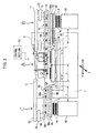
- FIG. 1 is a front view showing the whole of a laser machining apparatus according to a first embodiment of the invention.
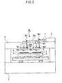
- FIG.1 is a front view showing the whole of a laser machining apparatus according to a first embodiment of the invention and FIG.2 is a front view showing a body of the laser machining apparatus.
- the inventive laser machining apparatus is composed of a body portion A thereof, a carrying-in unit B and a carrying-out unit C.
- An XY table 2 is disposed on a bed 1 of the body portion A.
- the XY table 2 is movable on the bed 1 horizontally in the X and Y directions.
- a plurality of (two in the figure) tables (work mounting sections) 3 is fixed on the XY table 2 separately by a distance L in the Y-axis direction.
- a plurality of holes connected to a hollow section inside is formed on the surface of the table 3.
- the hollow section is connected to a vacuum source not shown so that the table 3 can adsorb/release the workpiece 4.
- a gate-type column 5 is fixed on the bed 1.
- a laser oscillator 6 is mounted on the column 5.
- An acoustic opticalmodulator 7 for switching an optical path of a laser beam to a first optical path 30a or to a second optical path 30b is disposed on an optical axis of the laser oscillator 6.
- a laser irradiating section composed of mirrors 8a1 and 8a2 and a pair of optical scanner 9a and f ⁇ lens 10a is disposed on the first optical path 30a.
- a laser irradiating section composed of mirrors 8b1 and 8b2 and a pair of optical scanners 9b and f ⁇ lens 10b is disposed on the second optical path 30b.
- the acoustic optical modulator 7 switches the optical path of the laser beam outputted from the laser oscillator 6 and causes the beam to enter the optical scanner 9a or 9b through the mirrors 8a1 and 8a2 or through the mirrors 8b1 and 8b2. Then, the beam is positioned in the X and Y directions to machine the workpieces 4 by passing through the f ⁇ lens 10a or the f ⁇ lens 10b. That is, it is possible to machine the workpiece even when the workpiece 4 is put on only one table 3.
- a rail 11 permits a slider 12 in the carrying-in unit (supply-side transfer unit) B to reciprocate horizontally in the Y-direction in the figure.
- One end of a lifter 13 capable of extending/contracting in the vertical direction in the figure is fixed to the lower part of the slider 12.
- a plate 14 is fixed to the other end (edge) of the lifter 13.
- the plate 14 supports two work retaining tables (work retaining means) 16a and 16b movably in the vertical direction in the figure through an intermediary of guide rods 15.
- the work retaining tables 16a and 16b are disposed apart from each other in the Y-axis direction by a distance L.
- a plurality of holes connected to a hollow section inside is made at the lower face of the work retaining tables 16a and 16b.
- the hollow sections are connected to a vacuum source not shown so that the work retaining tables 16a and 16 can adsorb /release the workpiece 4.
- Springs 17 are provided contractedly between the work retaining table 16a and the plate 14 and between the work retaining table 16b and the plate 14, respectively, and bias the work retaining tables 16a and 16b away from the plate 14 to allow the motion of the plate 14 so that the plate 14 is not disturbed from continuously moving the other work retaining table when either one of the two work retaining tables contacts with the work receiving table 18 and its move is restricted.
- the position of the slider 12 indicated by a solid line in the figure indicates its standby position (right end of its moving range) and the position indicated by a dotted line indicates its supplying position described later.
- the work retaining tables 16a and 16b face, respectively, to the tables 3 on the XY table 2 positioned at the work delivering position.
- the plate 14 is positioned at the rising end.
- a supplying stocker 20 is disposed so as to face to the work retaining table 16a when the slider 12 is located at the standby position.
- Workpieces 4 are stacked on the upper face of the supplying stocker 20.
- a rail 19 is disposed at the position in the vertical direction interposed between the supplying stocker 20 and the work retaining tables 16a and 16b.
- a work receiving table (work mounting table) 18 is movable on the rail 19 horizontally in the Y-direction. It is noted that a standby position of the work receiving table 18 is the position when it is located at the left end of its moving range and at this time, the work receiving table 18 faces to the work retaining table 16b when the slider 12 is located at its standby position. When the work receiving table 18 is located at the right end of its moving range (receiving position), the work receiving table 18 faces to the work retaining table 16a when the slider 12 is located at its standby position.
- a rail 51 permits a slider 52 of the carrying-out unit (discharge-side transfer unit) C to reciprocate horizontally in the Y-direction in the figure.
- One end of a lifter 53 capable of extending/contracting in the vertical direction in the figure is fixed to the lower part of the slider 52.
- a plate 54 is fixed to the other end (edge) of the lifter 53.
- the plate 54 supports work retaining tables (work retaining means) 56a and 56b movably in the vertical direction in the figure through an intermediary of guide rods 55.
- the work retaining tables 56a and 56b are disposed apart from each other in the Y-axis direction by the distance L.
- a plurality of holes connected to a hollow section inside is made at the lower face of the work retaining tables 56a and 56b.
- the hollow sections are connected to a vacuum source not shown so that the work retaining tables 56a and 56b can adsorb/release the workpiece 4.
- Springs 57 are provided contractedly between the work retaining table 56a and the plate 54 and between the work retaining table 56b and the plate and bias the work retaining tables 56a and 56b away from the plate 54 to allow the motion of the plate 54 so that the plate 54 is not disturbed from continuously moving the other work retaining table when either one of the two work retaining tables contacts with the work receiving table and its move is restricted.
- the position of the slider 52 indicated by a solid line in the figure indicates its standby position (left end of its moving range).
- the work retaining tables 56a and 56b face, respectively, to the tables 3 on the XY table 2 positioned at the work delivering position.
- the plate 54 is positioned at its rising end.
- a discharging stocker 60 is disposed so as to face to the work retaining table 56a when the slider 52 is located at the standby position.
- the upper face of the discharging stocker 60 is made flat so as to be able to mount the workpieces 4 that have been machined.
- a rail 59 is disposed at the position in the vertical direction between the discharging stocker 60 and the work retaining tables 56a and 56b.
- a work receiving table (work mounting table) 58 is movable on the rail 59 horizontally in the Y-direction. It is noted that the standby position of the work receiving table 58 is the position when it is located at the right end of its moving range and at this time, the work receiving table 58 faces to the work retaining table 56b when the slider 52 is located at its standby position. When the work receiving table 58 is located at the left end of its moving range (discharging position) , the work receiving table 58 faces to the work retaining table 56a when the slider 52 is located at its standby position.
- a control section 50 controls the operation of the body portion A, the carrying-in unit B and the carrying-out unit C as well as an interleaf carrying-out unit D and an interleaf carrying-in unit E and others in a third embodiment described later, respectively.
- Steps 1 through 7 The operations carried out in Steps 1 through 7 described above will be referred to as a 'work retaining process' hereinafter.
- Steps 9 through 12 The operations carried out in Steps 9 through 12 described above will be referred to as a 'work mounting process' hereinafter.
- Steps 14 through 18 The operations carried out in Steps 14 through 18 described above will be referred to as a 'work carrying-out process' (part of work discharging process) hereinafter.
- the carrying-out unit C mounts the workpieces 4 retained by the work retaining tables 56a and 56b to the discharging stocker 60 through Steps 20 through 25 described below.
- Steps 20 through 25 will be referred to as a 'work discharging process' hereinafter.
- the work receiving tables 18 and 58 have been arranged so as to be movable in the horizontal direction in the embodiment described above, the work receiving table 18 may be fixed at its standby position.
- the slider 12 may be moved so that the work retaining table 16a faces to the work receiving table 18, instead of moving the work receiving table 18 in Step 3 described above.
- the work receiving table 58 may be also fixed at its standby position in the same manner.
- FIG. 3 is a front view showing the whole structure of the laser machining apparatus according to a second embodiment of the invention, wherein he same reference characters denote the same or corresponding parts with those in FIGs. 1 and 2 and an explanation thereof will be omitted here.
- a rail 62 is disposed at the position in the vertical direction between the rail 19 and the supplying stocker 20.
- An interleaf receiving table (interleaf mounting table) 61 is disposed on the rail 62 so as to be movable horizontally in the Y-direction.
- the standby position of the interleaf receiving table 61 is the position when the interleaf receiving table 61 is located at the left end of its moving range and at this time, the interleaf receiving table 61 faces, through an intermediary of the work receiving table 18, to the work retaining table 16b when the slider 12 is located at its standby position.
- the receiving position of the interleaf receiving table 61 is the position when it is located at the right end of its moving range and at this time, the interleaf receiving table 61 faces to the work retaining table 16a when the slider 12 is located at its standby position.
- Steps G1 through G12 described above will be referred to as an 'interleaved work retaining process' hereinafter.
- Steps G16 through G20 described above will be referred to as an 'interleaf retaining process' hereinafter.
- the carrying-in unit B carries out the work mounting process. It is noted that machining starts when the work mounting process ends.
- the operations for adsorbing/placing the workpiece 4 or the interleaf 4s by the work retaining tables 16a, 16b, 56a and 56b may be carried out reliably and quickly by providing elevator units to the supplying stocker 20 and the discharging stocker 60 so that the height of the uppermost workpiece 4 becomes the same with that of the workpiece 4 or the interleaf 4s mounted on the work receiving table 18 or 58 in the both cases of the first and second embodiments.
- FIG. 4 is a plan view showing a structure of a laser machining apparatus according to a third embodiment of the invention and FIG. 5 is a view in the direction of an arrow K in FIG. 4, wherein the same or corresponding parts with those in FIGs. 1 and 2 will be denoted by the same reference numerals and an explanation thereof will be omitted here. It is noted that a front view of the apparatus of the present embodiment is substantially the same with that shown in FIG. 1.
- An interleaf carrying-out unit (interleaf removing and carrying-out unit) D is disposed behind the carrying-in unit (supply-side transfer unit) B in FIG. 1 and an interleaf carrying-in unit (interleaving unit) E is disposed behind the carrying-out unit (discharge-side transfer unit) C in FIG. 1, respectively (see FIG. 4).
- the interleaf carrying-out unit D is a unit for retaining an interleaf 4s on a workpiece 4 placed on the supplying stocker 20 and for placing it on an interleaf discharging table 90.
- the interleaf carrying-in unit E is a unit for retaining the interleaf 4s placed on an interleaf supplying table 91 to place it on a workpiece 4 mounted on the discharging stocker 60. Because the structure of the interleaf carrying-out unit D is the same with that of the interleaf carrying-in unit E, a subscript (a) is appended to the reference numerals denoting the parts of the interleaf carrying-out unit D and a subscript (b) is appended to those of the interleaf carrying-in unit E.
- the interleaf carrying-in unit E will be explained below.
- a rail 81b which extends horizontally in the X direction in the figure supports a slider 82b of the interleaf carrying-in unit E so as to be reciprocally movable.
- One end of a lifter 83b which is capable of extending/contracting in the vertical direction in the figure is fixed to the lower part of the slider 82b.
- a plate 84b is fixed to the other end (edge) of the lifter 83b.
- the plate 84b supports a work retaining table (work retaining means) 86b so as to be movable in the vertical direction in the figure through an intermediary of guide rods 85b.
- a plurality of holes connected to a hollow section inside is made at the lower face of the work retaining table 86b.
- the hollow section is connected to a vacuum source not shown.
- Springs 87b are provided in contraction between the work retaining table 86b and the plate 84b to bias the work retaining table 86b away from the plate 84b.
- the standby position of the slider 82b is the position indicated by a solid line in the figure and the position indicated by a two-dot chain line in the figure is the interleaf supplying position.
- the work retaining table 86b is located at the position facing to the discharging stocker 60, i.e., the position overlapping with the work retaining table 56a at its standby position. It is noted that the plate 84b is located at its rising end when the slider 82b is located at its standby position.
- the interleaf supplying table 91 is disposed at the position facing to the slider 82b at its standby position. Interleaves 4s are stacked on the interleaf supplying table 91.
- the interleaf carrying-in unit E lowers the plate 84b so that the lower face of the work retaining table 86b contacts with the interleaf 4s stacked on the interleaf supplying table 91 and causes the work retaining table 86b to adsorb the interleaf 4s. Then, it stands by while raising the plate 84b to its standby position.
- the interleaf carrying-in unit E moves the slider 82b so that the work retaining table 86b faces to the discharging stocker 60. Then, it lowers the plate 84b so that the interleaf 4s adsorbed by the work retaining table 86b contacts with the workpiece 4 mounted on the discharging stocker 60 and then releases the adsorption to place the interleaf 4s on the workpiece 4. After that, it raises the plate 84b to return to its standby position. Then, it stands by while retaining a next interleaf 4s on the work retaining table 86b through Steps described above.
- the control section 50 controls the slider 82b and the slider 52 precisely so that they do not interfere each other. It is noted that the operation of the interleaf carrying-out unit D is the same with that of the interleaf carrying-in unit E described above and is readily understood from the operation of the interleaf carrying-in unit E, so that its explanation will be omitted here.
- Steps 1 through 7 and in Steps 5a through 5c described above will be referred to as a 'second work retaining process' hereinafter.
- Steps 9 through 12 and Step 9a described above will be referred to as a 'second work mounting process' hereinafter.
- Steps 15 through 18 the 'work carrying-out process' carried out in Steps 15 through 18 is the same with that in the first embodiment.
- the carrying-out unit C mounts the finished workpieces 4 retained by the work retaining tables 56a and 56b to the discharging stocker 60 through Steps 20 through 25 described below.
- the same steps with those in the first embodiment are carried out when no interleaf 4s is interposed between the workpieces 4 mounted on the supplying stocker 20.
- the third embodiment requires additional units and a larger installation area as compared to the second embodiment, it is advantageous in that it enables work efficiency to be improved considerably.
- the interleaves 4s may be utilized effectively by transferring those interleaves 4s discharged to the interleaf discharging table 90 to the interleaf supplying table 91.
- the work receiving table 18 may be fixed at its standby position in the third embodiment similarly to the case of the first embodiment.
- the slider 12 may be moved so that the work retaining table 16a faces to the work receiving table 18, instead of moving the work receiving table 18 in Step 3 described above.
- the interleaf carrying-out unit D may be operated while moving the slider 12.
- the work receiving table 58 may be also fixed at its standby position in the same manner.
- the machining accuracy may be improved by providing a work positioning device in each of the supplying stocker 20, the work receiving table 18 and the tables 3 in any embodiment of the first through third embodiments. It is also possible to prevent misalignment of the workpiece 4 or the interleaf 4s effectively by providing adsorption means in the work receiving tables 18 and 58, respectively.
- lifting unit may be provided at the work retaining tables 16a and 16b, respectively, so that they can move up and down, respectively.
- the case of two tables 3 has been described, it is possible to machine workpieces through the steps similar to those described above even when there are three tables or more.
- the present invention is also applicable to a case when a plurality of workpieces is mounted on one table.
Landscapes
- Engineering & Computer Science (AREA)
- Physics & Mathematics (AREA)
- Optics & Photonics (AREA)
- Mechanical Engineering (AREA)
- Plasma & Fusion (AREA)
- Laser Beam Processing (AREA)
Applications Claiming Priority (6)
| Application Number | Priority Date | Filing Date | Title |
|---|---|---|---|
| JP2003208535 | 2003-08-25 | ||
| JP2003208535 | 2003-08-25 | ||
| JP2004077065 | 2004-03-17 | ||
| JP2004077065 | 2004-03-17 | ||
| JP2004117328 | 2004-04-12 | ||
| JP2004117328A JP4215677B2 (ja) | 2003-08-25 | 2004-04-12 | レーザ加工機及びレーザ加工方法 |
Publications (2)
| Publication Number | Publication Date |
|---|---|
| EP1510482A1 EP1510482A1 (en) | 2005-03-02 |
| EP1510482B1 true EP1510482B1 (en) | 2006-11-29 |
Family
ID=34108568
Family Applications (1)
| Application Number | Title | Priority Date | Filing Date |
|---|---|---|---|
| EP04254950A Expired - Lifetime EP1510482B1 (en) | 2003-08-25 | 2004-08-18 | Laser machining apparatus and laser machining method |
Country Status (7)
| Country | Link |
|---|---|
| US (1) | US7132622B2 (ja) |
| EP (1) | EP1510482B1 (ja) |
| JP (1) | JP4215677B2 (ja) |
| KR (1) | KR101098076B1 (ja) |
| CN (1) | CN1590006B (ja) |
| DE (1) | DE602004003436T2 (ja) |
| TW (1) | TWI316437B (ja) |
Cited By (1)
| Publication number | Priority date | Publication date | Assignee | Title |
|---|---|---|---|---|
| CN101281762B (zh) * | 2007-04-05 | 2011-04-06 | 精工爱普生株式会社 | 介质输送单元及具备该介质输送单元的介质处理装置 |
Families Citing this family (29)
| Publication number | Priority date | Publication date | Assignee | Title |
|---|---|---|---|---|
| JP2005342748A (ja) * | 2004-06-01 | 2005-12-15 | Hitachi Via Mechanics Ltd | レーザ加工機 |
| JP4438661B2 (ja) * | 2005-03-28 | 2010-03-24 | 富士通株式会社 | 溶接装置および部材把持機構 |
| US7834293B2 (en) * | 2006-05-02 | 2010-11-16 | Electro Scientific Industries, Inc. | Method and apparatus for laser processing |
| US9029731B2 (en) | 2007-01-26 | 2015-05-12 | Electro Scientific Industries, Inc. | Methods and systems for laser processing continuously moving sheet material |
| DE102007023017B4 (de) * | 2007-05-15 | 2011-06-01 | Thyssenkrupp Lasertechnik Gmbh | Vorrichtung und Verfahren zum Herstellen von Tailored Blanks |
| JP4795377B2 (ja) * | 2008-03-27 | 2011-10-19 | 日立ビアメカニクス株式会社 | レーザ加工装置 |
| CN102217056A (zh) * | 2008-11-19 | 2011-10-12 | 应用材料股份有限公司 | 激光-划线工具架构 |
| JP5377086B2 (ja) * | 2009-06-04 | 2013-12-25 | 株式会社日立ハイテクノロジーズ | レーザ加工方法、レーザ加工装置及びソーラパネル製造方法 |
| CN101623796B (zh) * | 2009-08-13 | 2011-10-19 | 江苏金方圆数控机床有限公司 | 激光切割自动上下料分选码垛系统 |
| KR20120008345A (ko) * | 2010-07-16 | 2012-01-30 | 삼성모바일디스플레이주식회사 | 레이저 조사 장치 |
| TW201318749A (zh) * | 2011-11-15 | 2013-05-16 | 3D Circuit Taiwan | 三維電路雷射加工裝置 |
| CN103959452A (zh) * | 2011-11-16 | 2014-07-30 | 应用材料公司 | 激光划线系统、设备和方法 |
| CN102794569B (zh) * | 2012-08-31 | 2015-05-20 | 昆山市和博电子科技有限公司 | 晶片电阻激光自动划线设备 |
| JP5986470B2 (ja) * | 2012-09-25 | 2016-09-06 | ビアメカニクス株式会社 | レーザ加工機 |
| CN103600170B (zh) * | 2013-04-28 | 2015-08-26 | 宝山钢铁股份有限公司 | 一种纵向金属板上下料与切割方法及其系统 |
| KR101380727B1 (ko) * | 2013-05-23 | 2014-04-02 | 주식회사 제이플렉스 | 수동 프레스의 제품 취출시 제품 자동 인출방법 및 그 장치 |
| JP6190696B2 (ja) * | 2013-11-01 | 2017-08-30 | 株式会社東洋新薬 | 発泡性皮膚外用剤 |
| US10086471B2 (en) | 2014-03-31 | 2018-10-02 | Lincoln Global, Inc. | Laser enclosure with reciprocally movable shuttle structure, and method of using same |
| KR101638161B1 (ko) * | 2014-10-28 | 2016-07-08 | (주) 대동에스엠 | 자동차 부품의 너트 자동용접 시스템 |
| CN104860108B (zh) * | 2015-04-08 | 2016-10-26 | 广东硕源科技股份有限公司 | 一种自动切割堆叠设备 |
| CN106964903A (zh) * | 2017-03-31 | 2017-07-21 | 苏州川普光电有限公司 | 一种高精度导光板的加工设备 |
| CN107513600A (zh) * | 2017-08-31 | 2017-12-26 | 江苏密斯欧智能科技有限公司 | 一种表面改性热处理系统 |
| CN110153551A (zh) * | 2018-02-14 | 2019-08-23 | 镭射沃激光科技(深圳)有限公司 | 激光加工装置及利用此的激光加工方法 |
| CN109014607B (zh) * | 2018-08-21 | 2020-06-05 | 雅科薄膜(东莞)有限公司 | 一种聚乙烯塑料薄膜生产方法 |
| JP7449097B2 (ja) * | 2019-04-09 | 2024-03-13 | 株式会社ディスコ | レーザー加工装置 |
| JP7616792B2 (ja) * | 2021-05-27 | 2025-01-17 | ビアメカニクス株式会社 | レーザ加工装置 |
| CN114082679B (zh) * | 2021-11-17 | 2023-07-21 | 佛山中科灿光微电子设备有限公司 | 全自动测阻仪 |
| CN117226280B (zh) * | 2023-11-13 | 2024-03-19 | 珠海市申科谱工业科技有限公司 | 一种全自动激光打标设备 |
| KR102875687B1 (ko) | 2023-12-04 | 2025-10-23 | 국립공주대학교 산학협력단 | 레이저 가공을 이용한 흑연 분리판 제조방법 |
Family Cites Families (30)
| Publication number | Priority date | Publication date | Assignee | Title |
|---|---|---|---|---|
| US3730595A (en) * | 1971-11-30 | 1973-05-01 | Ibm | Linear carrier sender and receiver |
| US4027246A (en) * | 1976-03-26 | 1977-05-31 | International Business Machines Corporation | Automated integrated circuit manufacturing system |
| US4413820A (en) * | 1981-11-02 | 1983-11-08 | Libbey-Owens-Ford Company | Sheet handling apparatus and method |
| JPS61117063A (ja) * | 1984-11-13 | 1986-06-04 | Toshiba Mach Co Ltd | ポリシング装置におけるキヤリアおよび被加工物のロ−デイング装置 |
| US4995949A (en) * | 1986-03-21 | 1991-02-26 | Extrude Hone Corporation | Orifice sizing using chemical, electrochemical, electrical discharge machining, plating, coating techniques |
| JPH0439212A (ja) * | 1990-05-31 | 1992-02-10 | Pioneer Electron Corp | 板状ワーク分別搬送装置 |
| EP0483652A1 (en) * | 1990-10-31 | 1992-05-06 | Yamazaki Mazak Kabushiki Kaisha | Laser machining cell |
| US5229571A (en) * | 1991-07-08 | 1993-07-20 | Armco Steel Co., L.P. | High production laser welding assembly and method |
| JP3148287B2 (ja) * | 1991-07-15 | 2001-03-19 | 株式会社アマダ | レーザ複合加工装置 |
| US5500507A (en) * | 1991-09-30 | 1996-03-19 | Nippei Toyama Corporation | Laser beam machining device and laser beam machining method |
| JP3074930B2 (ja) | 1992-04-09 | 2000-08-07 | トヨタ自動車株式会社 | 2種類以上を製造可能な溶接パネル製造装置 |
| JPH06263245A (ja) * | 1993-03-09 | 1994-09-20 | Kubota Corp | 加工工程における工程間の板状体の移送方法 |
| JPH07297258A (ja) * | 1994-04-26 | 1995-11-10 | Tokyo Electron Ltd | 板状体の搬送装置 |
| JPH0985471A (ja) * | 1995-09-27 | 1997-03-31 | Hitachi Ltd | マーク付け装置 |
| EP0774320A1 (de) * | 1995-11-20 | 1997-05-21 | Elpatronic Ag | Verfahren zum Positionieren und Ausrichten von Werkstücken |
| US6013894A (en) * | 1997-02-10 | 2000-01-11 | Laserway, Inc. | Method and apparatus for laser texturing a magnetic recording disk substrate |
| US5856923A (en) * | 1997-03-24 | 1999-01-05 | Micron Technology, Inc. | Method for continuous, non lot-based integrated circuit manufacturing |
| JPH11192575A (ja) * | 1997-12-29 | 1999-07-21 | Shinozaki Seisakusho:Kk | レーザ加工システム |
| JP2000005835A (ja) * | 1998-06-22 | 2000-01-11 | Murata Mach Ltd | 板材位置決め装置 |
| US6449522B1 (en) * | 1998-11-17 | 2002-09-10 | Micro Devices, Inc. | Managing a semiconductor fabrication facility using wafer lot and cassette attributes |
| JP2000210865A (ja) * | 1999-01-25 | 2000-08-02 | Nichiden Mach Ltd | 平面研磨装置 |
| JP2001047280A (ja) * | 1999-08-03 | 2001-02-20 | Niigata Eng Co Ltd | 板材加工機用のワーク搬送装置およびワーク搬送方法 |
| JP3819197B2 (ja) * | 1999-11-15 | 2006-09-06 | 日立ビアメカニクス株式会社 | 板状ワーク供給装置及びこの装置を備えた板状ワーク孔明け装置 |
| JP4343386B2 (ja) * | 2000-03-17 | 2009-10-14 | 富士フイルム株式会社 | 印刷版自動露光装置 |
| JP3715196B2 (ja) * | 2000-11-13 | 2005-11-09 | 三菱電機株式会社 | レーザ加工装置 |
| US6653592B2 (en) * | 2001-01-30 | 2003-11-25 | Svein Andersen | Appliance for the surface treatment of coated elements |
| KR100702513B1 (ko) * | 2001-03-02 | 2007-04-02 | 삼성전자주식회사 | 테이프 마운팅 장치 |
| WO2003007350A2 (en) * | 2001-07-12 | 2003-01-23 | Speedline Manufacturing Company | Wafer jar loader method, system and apparatus |
| DE20304653U1 (de) * | 2002-07-09 | 2004-03-18 | Grob-Werke Burkhart Grob E.K. | Bearbeitungsstation |
| AU2003265634A1 (en) * | 2002-08-22 | 2004-03-11 | Integrated Dynamics Engineering, Inc. | Substrate processing system |
-
2004
- 2004-04-12 JP JP2004117328A patent/JP4215677B2/ja not_active Expired - Lifetime
- 2004-08-17 TW TW093124638A patent/TWI316437B/zh not_active IP Right Cessation
- 2004-08-18 EP EP04254950A patent/EP1510482B1/en not_active Expired - Lifetime
- 2004-08-18 DE DE602004003436T patent/DE602004003436T2/de not_active Expired - Lifetime
- 2004-08-19 US US10/921,224 patent/US7132622B2/en not_active Expired - Lifetime
- 2004-08-24 KR KR1020040066582A patent/KR101098076B1/ko not_active Expired - Lifetime
- 2004-08-25 CN CN2004100570355A patent/CN1590006B/zh not_active Expired - Lifetime
Cited By (1)
| Publication number | Priority date | Publication date | Assignee | Title |
|---|---|---|---|---|
| CN101281762B (zh) * | 2007-04-05 | 2011-04-06 | 精工爱普生株式会社 | 介质输送单元及具备该介质输送单元的介质处理装置 |
Also Published As
| Publication number | Publication date |
|---|---|
| TW200513333A (en) | 2005-04-16 |
| JP2005297007A (ja) | 2005-10-27 |
| CN1590006A (zh) | 2005-03-09 |
| US7132622B2 (en) | 2006-11-07 |
| CN1590006B (zh) | 2010-05-12 |
| KR20050022345A (ko) | 2005-03-07 |
| US20050045606A1 (en) | 2005-03-03 |
| JP4215677B2 (ja) | 2009-01-28 |
| KR101098076B1 (ko) | 2011-12-26 |
| DE602004003436T2 (de) | 2007-09-27 |
| EP1510482A1 (en) | 2005-03-02 |
| DE602004003436D1 (de) | 2007-01-11 |
| TWI316437B (en) | 2009-11-01 |
Similar Documents
| Publication | Publication Date | Title |
|---|---|---|
| EP1510482B1 (en) | Laser machining apparatus and laser machining method | |
| KR100989255B1 (ko) | 레이저 가공 장치 및 레이저 가공 방법 | |
| JP5283932B2 (ja) | 板状の工作物の加工のための機械設備 | |
| CN110480167B (zh) | 一种板材激光焊接的上料系统 | |
| JP4408682B2 (ja) | 電子部品装着装置 | |
| JPWO2009001497A1 (ja) | レーザ加工装置 | |
| KR20110137374A (ko) | 실장 장치 및 실장 방법 | |
| JPH09307286A (ja) | 電子部品実装装置およびその方法 | |
| EP3988260B1 (en) | Vacuum gripper and method for suction-holding workpiece | |
| JP5450338B2 (ja) | 電子部品実装機 | |
| CN111470330A (zh) | 工件堆叠装置 | |
| KR200342818Y1 (ko) | 사출물 스프루의 자동 절단장치 | |
| JP2024044558A (ja) | 金型交換装置 | |
| JP4027764B2 (ja) | ワークの固定方法 | |
| JP2003290851A (ja) | プレス機械のワーク搬送装置 | |
| CN214815725U (zh) | 水平式多工位除膜设备 | |
| US6797092B2 (en) | Method and apparatus for manufacturing monolithic ceramic electronic component | |
| JP7283851B2 (ja) | レーザ加工装置 | |
| JP2006134143A (ja) | 基板位置決め装置 | |
| KR102375376B1 (ko) | 라미네이팅 장치 | |
| KR101665868B1 (ko) | 2열 이송장치가 구비된 복합금형 장치 | |
| JP5440035B2 (ja) | 板状部材の支持装置 | |
| KR102637352B1 (ko) | 트레이 이송장치 및 이를 포함하는 세라믹기판의 자동분할시스템 | |
| JP5986470B2 (ja) | レーザ加工機 | |
| JP2577135B2 (ja) | 殖版機の刷版給排キャリア装置 |
Legal Events
| Date | Code | Title | Description |
|---|---|---|---|
| PUAI | Public reference made under article 153(3) epc to a published international application that has entered the european phase |
Free format text: ORIGINAL CODE: 0009012 |
|
| AK | Designated contracting states |
Kind code of ref document: A1 Designated state(s): AT BE BG CH CY CZ DE DK EE ES FI FR GB GR HU IE IT LI LU MC NL PL PT RO SE SI SK TR |
|
| AX | Request for extension of the european patent |
Extension state: AL HR LT LV MK |
|
| 17P | Request for examination filed |
Effective date: 20050822 |
|
| AKX | Designation fees paid |
Designated state(s): DE |
|
| GRAP | Despatch of communication of intention to grant a patent |
Free format text: ORIGINAL CODE: EPIDOSNIGR1 |
|
| GRAS | Grant fee paid |
Free format text: ORIGINAL CODE: EPIDOSNIGR3 |
|
| GRAA | (expected) grant |
Free format text: ORIGINAL CODE: 0009210 |
|
| AK | Designated contracting states |
Kind code of ref document: B1 Designated state(s): DE |
|
| REF | Corresponds to: |
Ref document number: 602004003436 Country of ref document: DE Date of ref document: 20070111 Kind code of ref document: P |
|
| PLBE | No opposition filed within time limit |
Free format text: ORIGINAL CODE: 0009261 |
|
| STAA | Information on the status of an ep patent application or granted ep patent |
Free format text: STATUS: NO OPPOSITION FILED WITHIN TIME LIMIT |
|
| 26N | No opposition filed |
Effective date: 20070830 |
|
| REG | Reference to a national code |
Ref country code: DE Ref legal event code: R081 Ref document number: 602004003436 Country of ref document: DE Owner name: VIA MECHANICS, LTD., JP Free format text: FORMER OWNER: HITACHI VIA MECHANICS, LTD., EBINA-SHI, JP Effective date: 20140226 Ref country code: DE Ref legal event code: R081 Ref document number: 602004003436 Country of ref document: DE Owner name: VIA MECHANICS, LTD., EBINA-SHI, JP Free format text: FORMER OWNER: HITACHI VIA MECHANICS, LTD., EBINA-SHI, KANAGAWA, JP Effective date: 20140226 |
|
| PGFP | Annual fee paid to national office [announced via postgrant information from national office to epo] |
Ref country code: DE Payment date: 20230627 Year of fee payment: 20 |
|
| REG | Reference to a national code |
Ref country code: DE Ref legal event code: R071 Ref document number: 602004003436 Country of ref document: DE |