EP1510482A1 - Laser machining apparatus and laser machining method - Google Patents
Laser machining apparatus and laser machining method Download PDFInfo
- Publication number
- EP1510482A1 EP1510482A1 EP04254950A EP04254950A EP1510482A1 EP 1510482 A1 EP1510482 A1 EP 1510482A1 EP 04254950 A EP04254950 A EP 04254950A EP 04254950 A EP04254950 A EP 04254950A EP 1510482 A1 EP1510482 A1 EP 1510482A1
- Authority
- EP
- European Patent Office
- Prior art keywords
- work
- retaining
- workpieces
- stocker
- discharging
- Prior art date
- Legal status (The legal status is an assumption and is not a legal conclusion. Google has not performed a legal analysis and makes no representation as to the accuracy of the status listed.)
- Granted
Links
- 238000003754 machining Methods 0.000 title claims abstract description 76
- 238000000034 method Methods 0.000 title claims abstract description 53
- 238000007599 discharging Methods 0.000 claims abstract description 72
- 230000001678 irradiating effect Effects 0.000 claims abstract description 20
- 230000000717 retained effect Effects 0.000 claims description 40
- 238000001179 sorption measurement Methods 0.000 claims description 16
- 238000010521 absorption reaction Methods 0.000 claims description 2
- 238000009434 installation Methods 0.000 abstract description 5
- 230000003287 optical effect Effects 0.000 description 12
- 230000000630 rising effect Effects 0.000 description 3
- 230000008602 contraction Effects 0.000 description 1
- 239000011347 resin Substances 0.000 description 1
- 229920005989 resin Polymers 0.000 description 1
Images


Classifications
-
- B—PERFORMING OPERATIONS; TRANSPORTING
- B65—CONVEYING; PACKING; STORING; HANDLING THIN OR FILAMENTARY MATERIAL
- B65H—HANDLING THIN OR FILAMENTARY MATERIAL, e.g. SHEETS, WEBS, CABLES
- B65H3/00—Separating articles from piles
- B65H3/08—Separating articles from piles using pneumatic force
- B65H3/0808—Suction grippers
- B65H3/0816—Suction grippers separating from the top of pile
-
- B—PERFORMING OPERATIONS; TRANSPORTING
- B23—MACHINE TOOLS; METAL-WORKING NOT OTHERWISE PROVIDED FOR
- B23K—SOLDERING OR UNSOLDERING; WELDING; CLADDING OR PLATING BY SOLDERING OR WELDING; CUTTING BY APPLYING HEAT LOCALLY, e.g. FLAME CUTTING; WORKING BY LASER BEAM
- B23K26/00—Working by laser beam, e.g. welding, cutting or boring
- B23K26/08—Devices involving relative movement between laser beam and workpiece
- B23K26/083—Devices involving movement of the workpiece in at least one axial direction
- B23K26/0838—Devices involving movement of the workpiece in at least one axial direction by using an endless conveyor belt
-
- B—PERFORMING OPERATIONS; TRANSPORTING
- B23—MACHINE TOOLS; METAL-WORKING NOT OTHERWISE PROVIDED FOR
- B23K—SOLDERING OR UNSOLDERING; WELDING; CLADDING OR PLATING BY SOLDERING OR WELDING; CUTTING BY APPLYING HEAT LOCALLY, e.g. FLAME CUTTING; WORKING BY LASER BEAM
- B23K26/00—Working by laser beam, e.g. welding, cutting or boring
- B23K26/08—Devices involving relative movement between laser beam and workpiece
- B23K26/10—Devices involving relative movement between laser beam and workpiece using a fixed support, i.e. involving moving the laser beam
-
- B—PERFORMING OPERATIONS; TRANSPORTING
- B23—MACHINE TOOLS; METAL-WORKING NOT OTHERWISE PROVIDED FOR
- B23K—SOLDERING OR UNSOLDERING; WELDING; CLADDING OR PLATING BY SOLDERING OR WELDING; CUTTING BY APPLYING HEAT LOCALLY, e.g. FLAME CUTTING; WORKING BY LASER BEAM
- B23K37/00—Auxiliary devices or processes, not specially adapted to a procedure covered by only one of the preceding main groups
- B23K37/04—Auxiliary devices or processes, not specially adapted to a procedure covered by only one of the preceding main groups for holding or positioning work
- B23K37/047—Auxiliary devices or processes, not specially adapted to a procedure covered by only one of the preceding main groups for holding or positioning work moving work to adjust its position between soldering, welding or cutting steps
-
- B—PERFORMING OPERATIONS; TRANSPORTING
- B65—CONVEYING; PACKING; STORING; HANDLING THIN OR FILAMENTARY MATERIAL
- B65H—HANDLING THIN OR FILAMENTARY MATERIAL, e.g. SHEETS, WEBS, CABLES
- B65H29/00—Delivering or advancing articles from machines; Advancing articles to or into piles
- B65H29/26—Delivering or advancing articles from machines; Advancing articles to or into piles by dropping the articles
- B65H29/32—Delivering or advancing articles from machines; Advancing articles to or into piles by dropping the articles from pneumatic, e.g. suction, carriers
-
- B—PERFORMING OPERATIONS; TRANSPORTING
- B65—CONVEYING; PACKING; STORING; HANDLING THIN OR FILAMENTARY MATERIAL
- B65H—HANDLING THIN OR FILAMENTARY MATERIAL, e.g. SHEETS, WEBS, CABLES
- B65H2220/00—Function indicators
- B65H2220/09—Function indicators indicating that several of an entity are present
-
- B—PERFORMING OPERATIONS; TRANSPORTING
- B65—CONVEYING; PACKING; STORING; HANDLING THIN OR FILAMENTARY MATERIAL
- B65H—HANDLING THIN OR FILAMENTARY MATERIAL, e.g. SHEETS, WEBS, CABLES
- B65H2406/00—Means using fluid
- B65H2406/30—Suction means
- B65H2406/34—Suction grippers
- B65H2406/342—Suction grippers being reciprocated in a rectilinear path
-
- B—PERFORMING OPERATIONS; TRANSPORTING
- B65—CONVEYING; PACKING; STORING; HANDLING THIN OR FILAMENTARY MATERIAL
- B65H—HANDLING THIN OR FILAMENTARY MATERIAL, e.g. SHEETS, WEBS, CABLES
- B65H2406/00—Means using fluid
- B65H2406/30—Suction means
- B65H2406/35—Other elements with suction surface, e.g. plate or wall
- B65H2406/351—Other elements with suction surface, e.g. plate or wall facing the surface of the handled material
-
- B—PERFORMING OPERATIONS; TRANSPORTING
- B65—CONVEYING; PACKING; STORING; HANDLING THIN OR FILAMENTARY MATERIAL
- B65H—HANDLING THIN OR FILAMENTARY MATERIAL, e.g. SHEETS, WEBS, CABLES
- B65H2701/00—Handled material; Storage means
- B65H2701/10—Handled articles or webs
- B65H2701/18—Form of handled article or web
- B65H2701/182—Piled package
- B65H2701/1826—Arrangement of sheets
- B65H2701/18264—Pile of alternate articles of different properties, e.g. pile of working sheets with intermediate sheet between each working sheet
-
- B—PERFORMING OPERATIONS; TRANSPORTING
- B65—CONVEYING; PACKING; STORING; HANDLING THIN OR FILAMENTARY MATERIAL
- B65H—HANDLING THIN OR FILAMENTARY MATERIAL, e.g. SHEETS, WEBS, CABLES
- B65H2701/00—Handled material; Storage means
- B65H2701/10—Handled articles or webs
- B65H2701/19—Specific article or web
- B65H2701/1928—Printing plate
-
- Y—GENERAL TAGGING OF NEW TECHNOLOGICAL DEVELOPMENTS; GENERAL TAGGING OF CROSS-SECTIONAL TECHNOLOGIES SPANNING OVER SEVERAL SECTIONS OF THE IPC; TECHNICAL SUBJECTS COVERED BY FORMER USPC CROSS-REFERENCE ART COLLECTIONS [XRACs] AND DIGESTS
- Y10—TECHNICAL SUBJECTS COVERED BY FORMER USPC
- Y10T—TECHNICAL SUBJECTS COVERED BY FORMER US CLASSIFICATION
- Y10T29/00—Metal working
- Y10T29/51—Plural diverse manufacturing apparatus including means for metal shaping or assembling
- Y10T29/5124—Plural diverse manufacturing apparatus including means for metal shaping or assembling with means to feed work intermittently from one tool station to another
Definitions
- the present invention relates to a laser machining apparatus comprising a plurality of laser irradiating sections and work mounting tables disposed so as to face to the laser irradiating sections and to a laser machining method using the laser machining apparatus.
- a laser machining apparatus having a plate-like work supplying unit, as disclosed in Japanese Patent Laid-open No. 2001-139170 for example, comprising work transferring means for transferring plate-like workpieces from a first work mounting section to a second work mounting section, workpiece thickness detecting means for detecting whether or not one workpiece is mounted on the second work mounting section, and work transfer control means for controlling, when the workpiece thickness detecting means detects that a plurality of workpieces are mounted on the second work mounting section, the work transferring means to return extra workpieces to the first work mounting section until when one workpiece is left on the second work mounting section.
- the transfer time may be shortened by providing the same number of second work mounting sections with the first work mounting sections and by taking out the workpieces from the plurality of work mounting sections in the same time, it is not practical because it requires a large installation area for the laser machining apparatus.
- a laser machining apparatus of the invention comprises:
- a laser machining method of the invention comprises:
- This arrangement allows the respective one of the work retaining means (16a, 16b) of the supply-side transfer unit (B) to retain a workpiece (4) while machining another workpiece (4) retained by the work mounting section (3) and when the machining ends, allows the respective one of the work retaining means (56a, 56b) of the discharge-side transfer unit (C) to retain the workpiece (4) which has been machined on the work mounting section (3).
- the supply-side transfer unit (B) to place the non-finished workpiece on the work mounting section (3) to start machining and allows the finished workpiece retained by the work retaining means (56a, 56b) of the discharge-side transfer unit (C) to be transferred to the discharging stocker (60).
- the inventive laser machining apparatus further comprises work mounting tables (18, 58) which are capable of mounting workpieces (4) and are disposed at least in the supply-side transfer unit (B) or the discharge-side transfer unit (C).
- This arrangement allows the workpieces (4) to be temporarily retained by the work mounting tables (18, 58) in retaining the workpieces (4) by the work retaining means (16a, 16b or 56a, 56b).
- the work mounting table (18) disposed in the supply-side transfer unit (B) may be arranged so as to be movable in amono-axial direction and an interleaf mounting table (61) whereon an interleaf (4s) may be mounted may be provided such that the interleaf mounting table (61) is disposed at the vertically intermediate position between the movable work mounting table (18) and the supplying stocker (20).
- the interleaf mounting table (61) may be arranged to be movable in a mono-axial direction.
- the work mounting table (58) disposed on the side of the discharge-side transfer unit (C) may be also arranged so as to be movable in a mono-axial direction.
- an interleaf removing and carrying-out unit (D) for removing an interleaf (4s) placed on the non-finished workpiece from the workpiece (4) and an interleaving unit (E) for placing the interleaf (4s) on the workpiece whose machining has been finished and to dispose the interleaf removing and carrying-out unit (D) on the side of the supplying stocker (20) and to dispose the interleaving unit (E) on the side of the discharging stocker (60).
- the inventive apparatus allows the machining efficiency to be improved because it retains all workpieces (4) to be machined next by the supply-side work retaining means while machining other workpieces (4) and it carries in or out a plurality of workpieces (4) simultaneously by one time of conveyance. Still more, the invention allows an installation area of the apparatus to be reduced by providing one each supplying and discharging stockers for the plurality of work mounting sections (tables).
- FIG. 1 is a front view showing the whole of a laser machining apparatus according to a first embodiment of the invention.
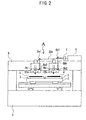
- FIG. 2 is a front view showing of a body portion of the laser machining apparatus.
- FIG. 3 is a front view showing the whole of a laser machining apparatus according to a second embodiment of the invention.
- FIG. 4 is a plan view showing the whole of a laser machining apparatus according to a third embodiment of the invention.
- FIG. 5 is a view taken in the direction of an arrow K in FIG. 4.
- FIG.1 is a front view showing the whole of a laser machining apparatus according to a first embodiment of the invention and FIG.2 is a front view showing a body of the laser machining apparatus.
- the inventive laser machining apparatus is composed of a body portion A thereof, a carrying-in unit B and a carrying-out unit C.
- An XY table 2 is disposed on a bed 1 of the body portion A.
- the XY table 2 is movable on the bed 1 horizontally in the X and Y directions.
- a plurality of (two in the figure) tables (work mounting sections) 3 is fixed on the XY table 2 separately by a distance L in the Y-axis direction.
- a plurality of holes connected to a hollow section inside is formed on the surface of the table 3.
- the hollow section is connected to a vacuum source not shown so that the table 3 can adsorb/release the workpiece 4.
- a gate-type column 5 is fixed on the bed 1.
- a laser oscillator 6 is mounted on the column 5.
- An acoustic opticalmodulator 7 for switching an optical path of a laser beam to a first optical path 30a or to a second optical path 30b is disposed on an optical axis of the laser oscillator 6.
- a laser irradiating section composed of mirrors 8a1 and 8a2 and a pair of optical scanner 9a and f ⁇ lens 10a is disposed on the first optical path 30a.
- a laser irradiating section composed of mirrors 8b1 and 8b2 and a pair of optical scanners 9b and f ⁇ lens 10b is disposed on the second optical path 30b.
- the acoustic optical modulator 7 switches the optical path of the laser beam outputted from the laser oscillator 6 and causes the beam to enter the optical scanner 9a or 9b through the mirrors 8a1 and 8a2 or through the mirrors 8b1 and 8b2. Then, the beam is positioned in the X and Y directions to machine the workpieces 4 by passing through the f ⁇ lens 10a or the f ⁇ lens 10b. That is, it is possible to machine the workpiece even when the workpiece 4 is put on only one table 3.
- a rail 11 permits a slider 12 in the carrying-in unit (supply-side transfer unit) B to reciprocate horizontally in the Y-direction in the figure.
- One end of a lifter 13 capable of extending/contracting in the vertical direction in the figure is fixed to the lower part of the slider 12.
- a plate 14 is fixed to the other end (edge) of the lifter 13.
- the plate 14 supports two work retaining tables (work retaining means) 16a and 16b movably in the vertical direction in the figure through an intermediary of guide rods 15.
- the work retaining tables 16a and 16b are disposed apart from each other in the Y-axis direction by a distance L.
- a plurality of holes connected to a hollow section inside is made at the lower face of the work retaining tables 16a and 16b.
- the hollow sections are connected to a vacuum source not shown so that the work retaining tables 16a and 16 can adsorb /release the workpiece 4.
- Springs 17 are provided contractedly between the work retaining table 16a and the plate 14 and between the work retaining table 16b and the plate 14, respectively, and bias the work retaining tables 16a and 16b away from the plate 14 to allow the motion of the plate 14 so that the plate 14 is not disturbed from continuously moving the other work retaining table when either one of the two work retaining tables contacts with the work receiving table 18 and its move is restricted.
- the position of the slider 12 indicated by a solid line in the figure indicates its standby position (right end of its moving range) and the position indicated by a dotted line indicates its supplying position described later.
- the work retaining tables 16a and 16b face, respectively, to the tables 3 on the XY table 2 positioned at the work delivering position.
- the plate 14 is positioned at the rising end.
- a supplying stocker 20 is disposed so as to face to the work retaining table 16a when the slider 12 is located at the standby position.
- Workpieces 4 are stacked on the upper face of the supplying stocker 20.
- a rail 19 is disposed at the position in the vertical direction interposed between the supplying stocker 20 and the work retaining tables 16a and 16b.
- a work receiving table (work mounting table) 18 is movable on the rail 19 horizontally in the Y-direction. It is noted that a standby position of the work receiving table 18 is the position when it is located at the left end of its moving range and at this time, the work receiving table 18 faces to the work retaining table 16b when the slider 12 is located at its standby position. When the work receiving table 18 is located at the right end of its moving range (receiving position), the work receiving table 18 faces to the work retaining table 16a when the slider 12 is located at its standby position.
- a rail 51 permits a slider 52 of the carrying-out unit (discharge-side transfer unit) C to reciprocate horizontally in the Y-direction in the figure.
- One end of a lifter 53 capable of extending/contracting in the vertical direction in the figure is fixed to the lower part of the slider 52.
- a plate 54 is fixed to the other end (edge) of the lifter 53.
- the plate 54 supports work retaining tables (work retaining means) 56a and 56b movably in the vertical direction in the figure through an intermediary of guide rods 55.
- the work retaining tables 56a and 56b are disposed apart from each other in the Y-axis direction by the distance L.
- a plurality of holes connected to a hollow section inside is made at the lower face of the work retaining tables 56a and 56b.
- the hollow sections are connected to a vacuum source not shown so that the work retaining tables 56a and 56b can adsorb/release the workpiece 4.
- Springs 57 are provided contractedly between the work retaining table 56a and the plate 54 and between the work retaining table 56b and the plate and bias the work retaining tables 56a and 56b away from the plate 54 to allow the motion of the plate 54 so that the plate 54 is not disturbed from continuously moving the other work retaining table when either one of the two work retaining tables contacts with the work receiving table and its move is restricted.
- the position of the slider 52 indicated by a solid line in the figure indicates its standby position (left end of its moving range).
- the work retaining tables 56a and 56b face, respectively, to the tables 3 on the XY table 2 positioned at the work delivering position.
- the plate 54 is positioned at its rising end.
- a discharging stocker 60 is disposed so as to face to the work retaining table 56a when the slider 52 is located at the standby position.
- the upper face of the discharging stocker 60 is made flat so as to be able to mount the workpieces 4 that have been machined.
- a rail 59 is disposed at the position in the vertical direction between the discharging stocker 60 and the work retaining tables 56a and 56b.
- a work receiving table (work mounting table) 58 is movable on the rail 59 horizontally in the Y-direction. It is noted that the standby position of the work receiving table 58 is the position when it is located at the right end of its moving range and at this time, the work receiving table 58 faces to the work retaining table 56b when the slider 52 is located at its standby position. When the work receiving table 58 is located at the left end of its moving range (discharging position) , the work receiving table 58 faces to the work retaining table 56a when the slider 52 is located at its standby position.
- a control section 50 controls the operation of the body portion A, the carrying-in unit B and the carrying-out unit C as well as an interleaf carrying-out unit D and an interleaf carrying-in unit E and others in a third embodiment described later, respectively.
- Steps 1 through 7 The operations carried out in Steps 1 through 7 described above will be referred to as a 'work retaining process' hereinafter.
- Steps 9 through 12 The operations carried out in Steps 9 through 12 described above will be referred to as a 'work mounting process' hereinafter.
- Steps 14 through 18 The operations carried out in Steps 14 through 18 described above will be referred to as a 'work carrying-out process' (part of work discharging process) hereinafter.
- the carrying-out unit C mounts the workpieces 4 retained by the work retaining tables 56a and 56b to the discharging stocker 60 through Steps 20 through 25 described below.
- Steps 20 through 25 will be referred to as a 'work discharging process' hereinafter.
- the work receiving tables 18 and 58 have been arranged so as to be movable in the horizontal direction in the embodiment described above, the work receiving table 18 may be fixed at its standby position.
- the slider 12 may be moved so that the work retaining table 16a faces to the work receiving table 18, instead of moving the work receiving table 18 in Step 3 described above.
- the work receiving table 58 may be also fixed at its standby position in the same manner.
- FIG. 3 is a front view showing the whole structure of the laser machining apparatus according to a second embodiment of the invention, wherein he same reference characters denote the same or corresponding parts with those in FIGs. 1 and 2 and an explanation thereof will be omitted here.
- a rail 62 is disposed at the position in the vertical direction between the rail 19 and the supplying stocker 20.
- An interleaf receiving table (interleaf mounting table) 61 is disposed on the rail 62 so as to be movable horizontally in the Y-direction.
- the standby position of the interleaf receiving table 61 is the position when the interleaf receiving table 61 is located at the left end of its moving range and at this time, the interleaf receiving table 61 faces, through an intermediary of the work receiving table 18, to the work retaining table 16b when the slider 12 is located at its standby position.
- the receiving position of the interleaf receiving table 61 is the position when it is located at the right end of its moving range and at this time, the interleaf receiving table 61 faces to the work retaining table 16a when the slider 12 is located at its standby position.
- Steps G1 through G12 described above will be referred to as an 'interleaved work retaining process' hereinafter.
- Steps G16 through G20 described above will be referred to as an 'interleaf retaining process' hereinafter.
- the carrying-in unit B carries out the work mounting process. It is noted that machining starts when the work mounting process ends.
- the operations for adsorbing/placing the workpiece 4 or the interleaf 4s by the work retaining tables 16a, 16b, 56a and 56b may be carried out reliably and quickly by providing elevator units to the supplying stocker 20 and the discharging stocker 60 so that the height of the uppermost workpiece 4 becomes the same with that of the workpiece 4 or the interleaf 4s mounted on the work receiving table 18 or 58 in the both cases of the first and second embodiments.
- FIG. 4 is a plan view showing a structure of a laser machining apparatus according to a third embodiment of the invention and FIG. 5 is a view in the direction of an arrow K in FIG. 4, wherein the same or corresponding parts with those in FIGs. 1 and 2 will be denoted by the same reference numerals and an explanation thereof will be omitted here. It is noted that a front view of the apparatus of the present embodiment is substantially the same with that shown in FIG. 1.
- An interleaf carrying-out unit (interleaf removing and carrying-out unit) D is disposed behind the carrying-in unit (supply-side transfer unit) B in FIG. 1 and an interleaf carrying-in unit (interleaving unit) E is disposed behind the carrying-out unit (discharge-side transfer unit) C in FIG. 1, respectively (see FIG. 4).
- the interleaf carrying-out unit D is a unit for retaining an interleaf 4s on a workpiece 4 placed on the supplying stocker 20 and for placing it on an interleaf discharging table 90.
- the interleaf carrying-in unit E is a unit for retaining the interleaf 4s placed on an interleaf supplying table 91 to place it on a workpiece 4 mounted on the discharging stocker 60. Because the structure of the interleaf carrying-out unit D is the same with that of the interleaf carrying-in unit E, a subscript (a) is appended to the reference numerals denoting the parts of the interleaf carrying-out unit D and a subscript (b) is appended to those of the interleaf carrying-in unit E.
- the interleaf carrying-in unit E will be explained below.
- a rail 81b which extends horizontally in the X direction in the figure supports a slider 82b of the interleaf carrying-in unit E so as to be reciprocally movable.
- One end of a lifter 83b which is capable of extending/contracting in the vertical direction in the figure is fixed to the lower part of the slider 82b.
- a plate 84b is fixed to the other end (edge) of the lifter 83b.
- the plate 84b supports a work retaining table (work retaining means) 86b so as to be movable in the vertical direction in the figure through an intermediary of guide rods 85b.
- a plurality of holes connected to a hollow section inside is made at the lower face of the work retaining table 86b.
- the hollow section is connected to a vacuum source not shown.
- Springs 87b are provided in contraction between the work retaining table 86b and the plate 84b to bias the work retaining table 86b away from the plate 84b.
- the standby position of the slider 82b is the position indicated by a solid line in the figure and the position indicated by a two-dot chain line in the figure is the interleaf supplying position.
- the work retaining table 86b is located at the position facing to the discharging stocker 60, i.e., the position overlapping with the work retaining table 56a at its standby position. It is noted that the plate 84b is located at its rising end when the slider 82b is located at its standby position.
- the interleaf supplying table 91 is disposed at the position facing to the slider 82b at its standby position. Interleaves 4s are stacked on the interleaf supplying table 91.
- the interleaf carrying-in unit E lowers the plate 84b so that the lower face of the work retaining table 86b contacts with the interleaf 4s stacked on the interleaf supplying table 91 and causes the work retaining table 86b to adsorb the interleaf 4s. Then, it stands by while raising the plate 84b to its standby position.
- the interleaf carrying-in unit E moves the slider 82b so that the work retaining table 86b faces to the discharging stocker 60. Then, it lowers the plate 84b so that the interleaf 4s adsorbed by the work retaining table 86b contacts with the workpiece 4 mounted on the discharging stocker 60 and then releases the adsorption to place the interleaf 4s on the workpiece 4. After that, it raises the plate 84b to return to its standby position. Then, it stands by while retaining a next interleaf 4s on the work retaining table 86b through Steps described above.
- the control section 50 controls the slider 82b and the slider 52 precisely so that they do not interfere each other. It is noted that the operation of the interleaf carrying-out unit D is the same with that of the interleaf carrying-in unit E described above and is readily understood from the operation of the interleaf carrying-in unit E, so that its explanation will be omitted here.
- Steps 1 through 7 and in Steps 5a through 5c described above will be referred to as a 'second work retaining process' hereinafter.
- Steps 9 through 12 and Step 9a described above will be referred to as a 'second work mounting process' hereinafter.
- Steps 15 through 18 the 'work carrying-out process' carried out in Steps 15 through 18 is the same with that in the first embodiment.
- the carrying-out unit C mounts the finished workpieces 4 retained by the work retaining tables 56a and 56b to the discharging stocker 60 through Steps 20 through 25 described below.
- the same steps with those in the first embodiment are carried out when no interleaf 4s is interposed between the workpieces 4 mounted on the supplying stocker 20.
- the third embodiment requires additional units and a larger installation area as compared to the second embodiment, it is advantageous in that it enables work efficiency to be improved considerably.
- the interleaves 4s may be utilized effectively by transferring those interleaves 4s discharged to the interleaf discharging table 90 to the interleaf supplying table 91.
- the work receiving table 18 may be fixed at its standby position in the third embodiment similarly to the case of the first embodiment.
- the slider 12 may be moved so that the work retaining table 16a faces to the work receiving table 18, instead of moving the work receiving table 18 in Step 3 described above.
- the interleaf carrying-out unit D may be operated while moving the slider 12.
- the work receiving table 58 may be also fixed at its standby position in the same manner.
- the machining accuracy may be improved by providing a work positioning device in each of the supplying stocker 20, the work receiving table 18 and the tables 3 in any embodiment of the first through third embodiments. It is also possible to prevent misalignment of the workpiece 4 or the interleaf 4s effectively by providing adsorption means in the work receiving tables 18 and 58, respectively.
- lifting unit may be provided at the work retaining tables 16a and 16b, respectively, so that they can move up and down, respectively.
- the case of two tables 3 has been described, it is possible to machine workpieces through the steps similar to those described above even when there are three tables or more.
- the present invention is also applicable to a case when a plurality of workpieces is mounted on one table.
Abstract
Description
- The present invention relates to a laser machining apparatus comprising a plurality of laser irradiating sections and work mounting tables disposed so as to face to the laser irradiating sections and to a laser machining method using the laser machining apparatus.
- As a prior art laser machining apparatus, there has been known a laser machining apparatus having a plate-like work supplying unit, as disclosed in Japanese Patent Laid-open No. 2001-139170 for example, comprising work transferring means for transferring plate-like workpieces from a first work mounting section to a second work mounting section, workpiece thickness detecting means for detecting whether or not one workpiece is mounted on the second work mounting section, and work transfer control means for controlling, when the workpiece thickness detecting means detects that a plurality of workpieces are mounted on the second work mounting section, the work transferring means to return extra workpieces to the first work mounting section until when one workpiece is left on the second work mounting section.
- However, in case of the laser machining apparatus comprising a plurality of work mounting sections, it takes time to transfer workpieces and the machining efficiency drops if the workpieces are to be transferred one by one.
- Still more, although the transfer time may be shortened by providing the same number of second work mounting sections with the first work mounting sections and by taking out the workpieces from the plurality of work mounting sections in the same time, it is not practical because it requires a large installation area for the laser machining apparatus.
- It is an object of the invention to solve the aforementioned problems by providing a laser machining apparatus, and a laser machining method, that require no large installation area while improving its work efficiency.
- A laser machining apparatus of the invention comprises:
- a body portion (A) of the laser machining apparatus having a plurality of laser irradiating sections (10a, 10b) disposed in line in a horizontal mono-axial direction and work mounting sections (3) disposed in line so as to face to the laser irradiating sections;
- a supplying stocker (20) for supplying workpieces (4);
- a discharging stocker (60) for discharging the workpieces;
- a supply-side transfer unit (B) having work retaining means (16a, 16b) capable of attaching/detaching the workpieces (4) and of the same number with the laser irradiating sections, and moving the work retaining means in the vertical and horizontal directions; and
- a discharge-side transfer unit (C) having work retaining means (56a, 56b) capable of attaching/detaching the workpieces (4) and of the same number with the laser irradiating sections (10a, 10b), and moving the work retaining means (56a, 56b) in the vertical and horizontal directions: and characterized in that
-
- A laser machining method of the invention comprises:
- a work retaining process (
Steps 1 through 7) of moving a plurality of supply-side work retaining means (16a, 16b) in the vertical and horizontal directions and of adsorbing and retaining workpieces (4) from one supplying stocker (20) by the respective work retaining means (16a, 16b); - a work mounting process (Steps 9 through 12) of moving the supply-side work retaining means (16a, 16b) to the work mounting sections (3) disposed so as to face to the laser irradiating sections of the same number with the work retaining means and of releasing the work retaining means to place the workpieces (4) retained by the plurality of work retaining means to the work mounting sections (3); and
- a work discharging process (
Steps 20 through 25) of retaining the plurality of finished workpieces (4) to the discharge-side work retaining means (56a, 56b) after machining the workpieces (4) placed on the work mounting sections (3) by the plurality of laser irradiating sections , moving the work retaining means in the vertical and horizontal directions and releasing the respective work retaining means to discharge the plurality of workpieces (4) retained by the discharge-side work retaining means to one discharging stocker (60). -
- This arrangement allows the respective one of the work retaining means (16a, 16b) of the supply-side transfer unit (B) to retain a workpiece (4) while machining another workpiece (4) retained by the work mounting section (3) and when the machining ends, allows the respective one of the work retaining means (56a, 56b) of the discharge-side transfer unit (C) to retain the workpiece (4) which has been machined on the work mounting section (3). Then, after removing the finished workpiece (4) from the work mounting section (3) by the work retaining means, it allows the supply-side transfer unit (B) to place the non-finished workpiece on the work mounting section (3) to start machining and allows the finished workpiece retained by the work retaining means (56a, 56b) of the discharge-side transfer unit (C) to be transferred to the discharging stocker (60).
- Preferably, the inventive laser machining apparatus further comprises work mounting tables (18, 58) which are capable of mounting workpieces (4) and are disposed at least in the supply-side transfer unit (B) or the discharge-side transfer unit (C). This arrangement allows the workpieces (4) to be temporarily retained by the work mounting tables (18, 58) in retaining the workpieces (4) by the work retaining means (16a, 16b or 56a, 56b).
- Further, the work mounting table (18) disposed in the supply-side transfer unit (B) may be arranged so as to be movable in amono-axial direction and an interleaf mounting table (61) whereon an interleaf (4s) may be mounted may be provided such that the interleaf mounting table (61) is disposed at the vertically intermediate position between the movable work mounting table (18) and the supplying stocker (20).
- Still more, the interleaf mounting table (61) may be arranged to be movable in a mono-axial direction.
- The work mounting table (58) disposed on the side of the discharge-side transfer unit (C) may be also arranged so as to be movable in a mono-axial direction.
- It is also possible to provide an interleaf removing and carrying-out unit (D) for removing an interleaf (4s) placed on the non-finished workpiece from the workpiece (4) and an interleaving unit (E) for placing the interleaf (4s) on the workpiece whose machining has been finished and to dispose the interleaf removing and carrying-out unit (D) on the side of the supplying stocker (20) and to dispose the interleaving unit (E) on the side of the discharging stocker (60).
- The inventive apparatus allows the machining efficiency to be improved because it retains all workpieces (4) to be machined next by the supply-side work retaining means while machining other workpieces (4) and it carries in or out a plurality of workpieces (4) simultaneously by one time of conveyance. Still more, the invention allows an installation area of the apparatus to be reduced by providing one each supplying and discharging stockers for the plurality of work mounting sections (tables).
- The specific nature of the invention, as well as other objects, uses and advantages thereof, will clearly appear from the following description and from the accompanying drawings wherein the same reference characters denote the same or corresponding parts throughout the several views.
- FIG. 1 is a front view showing the whole of a laser machining apparatus according to a first embodiment of the invention.
FIG. 2 is a front view showing of a body portion of the laser machining apparatus.
FIG. 3 is a front view showing the whole of a laser machining apparatus according to a second embodiment of the invention.
FIG. 4 is a plan view showing the whole of a laser machining apparatus according to a third embodiment of the invention.
FIG. 5 is a view taken in the direction of an arrow K in FIG. 4. - Modes for carrying out the invention will be explained below with reference to exemplary embodiments thereof and the accompanying drawings.
- FIG.1 is a front view showing the whole of a laser machining apparatus according to a first embodiment of the invention and FIG.2 is a front view showing a body of the laser machining apparatus. As shown in FIG. 1, the inventive laser machining apparatus is composed of a body portion A thereof, a carrying-in unit B and a carrying-out unit C.
- The structure of the body portion A will be explained at first with reference to FIGs. 1 and 2. An XY table 2 is disposed on a
bed 1 of the body portion A. The XY table 2 is movable on thebed 1 horizontally in the X and Y directions. A plurality of (two in the figure) tables (work mounting sections) 3 is fixed on the XY table 2 separately by a distance L in the Y-axis direction. A plurality of holes connected to a hollow section inside is formed on the surface of the table 3. The hollow section is connected to a vacuum source not shown so that the table 3 can adsorb/release theworkpiece 4. - A gate-
type column 5 is fixed on thebed 1. Alaser oscillator 6 is mounted on thecolumn 5. Anacoustic opticalmodulator 7 for switching an optical path of a laser beam to a firstoptical path 30a or to a secondoptical path 30b is disposed on an optical axis of thelaser oscillator 6. A laser irradiating section composed of mirrors 8a1 and 8a2 and a pair ofoptical scanner 9a and flens 10a is disposed on the firstoptical path 30a. A laser irradiating section composed of mirrors 8b1 and 8b2 and a pair ofoptical scanners 9b and flens 10b is disposed on the secondoptical path 30b. - Next, an operation of the body portion A of the laser machining apparatus in machining workpieces will be explained. The acoustic
optical modulator 7 switches the optical path of the laser beam outputted from thelaser oscillator 6 and causes the beam to enter theoptical scanner workpieces 4 by passing through the flens 10a or the flens 10b. That is, it is possible to machine the workpiece even when theworkpiece 4 is put on only one table 3. - As shown in FIG. 1, a
rail 11 permits aslider 12 in the carrying-in unit (supply-side transfer unit) B to reciprocate horizontally in the Y-direction in the figure. One end of alifter 13 capable of extending/contracting in the vertical direction in the figure is fixed to the lower part of theslider 12. Aplate 14 is fixed to the other end (edge) of thelifter 13. Theplate 14 supports two work retaining tables (work retaining means) 16a and 16b movably in the vertical direction in the figure through an intermediary ofguide rods 15. The work retaining tables 16a and 16b are disposed apart from each other in the Y-axis direction by a distance L. A plurality of holes connected to a hollow section inside is made at the lower face of the work retaining tables 16a and 16b. The hollow sections are connected to a vacuum source not shown so that the work retaining tables 16a and 16 can adsorb /release theworkpiece 4.Springs 17 are provided contractedly between the work retaining table 16a and theplate 14 and between the work retaining table 16b and theplate 14, respectively, and bias the work retaining tables 16a and 16b away from theplate 14 to allow the motion of theplate 14 so that theplate 14 is not disturbed from continuously moving the other work retaining table when either one of the two work retaining tables contacts with the work receiving table 18 and its move is restricted. - The position of the
slider 12 indicated by a solid line in the figure indicates its standby position (right end of its moving range) and the position indicated by a dotted line indicates its supplying position described later. When theslider 12 is located at the supplying position, the work retaining tables 16a and 16b face, respectively, to the tables 3 on the XY table 2 positioned at the work delivering position. It is noted that when theslider 12 is located at the standby position, theplate 14 is positioned at the rising end. A supplyingstocker 20 is disposed so as to face to the work retaining table 16a when theslider 12 is located at the standby position.Workpieces 4 are stacked on the upper face of the supplyingstocker 20. - A
rail 19 is disposed at the position in the vertical direction interposed between the supplyingstocker 20 and the work retaining tables 16a and 16b. A work receiving table (work mounting table) 18 is movable on therail 19 horizontally in the Y-direction. It is noted that a standby position of the work receiving table 18 is the position when it is located at the left end of its moving range and at this time, the work receiving table 18 faces to the work retaining table 16b when theslider 12 is located at its standby position. When the work receiving table 18 is located at the right end of its moving range (receiving position), the work receiving table 18 faces to the work retaining table 16a when theslider 12 is located at its standby position. - A
rail 51 permits aslider 52 of the carrying-out unit (discharge-side transfer unit) C to reciprocate horizontally in the Y-direction in the figure. One end of alifter 53 capable of extending/contracting in the vertical direction in the figure is fixed to the lower part of theslider 52. Aplate 54 is fixed to the other end (edge) of thelifter 53. Theplate 54 supports work retaining tables (work retaining means) 56a and 56b movably in the vertical direction in the figure through an intermediary ofguide rods 55. The work retaining tables 56a and 56b are disposed apart from each other in the Y-axis direction by the distance L. A plurality of holes connected to a hollow section inside is made at the lower face of the work retaining tables 56a and 56b. The hollow sections are connected to a vacuum source not shown so that the work retaining tables 56a and 56b can adsorb/release theworkpiece 4.Springs 57 are provided contractedly between the work retaining table 56a and theplate 54 and between the work retaining table 56b and the plate and bias the work retaining tables 56a and 56b away from theplate 54 to allow the motion of theplate 54 so that theplate 54 is not disturbed from continuously moving the other work retaining table when either one of the two work retaining tables contacts with the work receiving table and its move is restricted. - The position of the
slider 52 indicated by a solid line in the figure indicates its standby position (left end of its moving range). When theslider 52 is located at the discharging position (not shown) at the right end of the moving range, the work retaining tables 56a and 56b face, respectively, to the tables 3 on the XY table 2 positioned at the work delivering position. It is noted that when theslider 52 is located at the standby position, theplate 54 is positioned at its rising end. A dischargingstocker 60 is disposed so as to face to the work retaining table 56a when theslider 52 is located at the standby position. The upper face of the dischargingstocker 60 is made flat so as to be able to mount theworkpieces 4 that have been machined. - A
rail 59 is disposed at the position in the vertical direction between the dischargingstocker 60 and the work retaining tables 56a and 56b. A work receiving table (work mounting table) 58 is movable on therail 59 horizontally in the Y-direction. It is noted that the standby position of the work receiving table 58 is the position when it is located at the right end of its moving range and at this time, the work receiving table 58 faces to the work retaining table 56b when theslider 52 is located at its standby position. When the work receiving table 58 is located at the left end of its moving range (discharging position) , the work receiving table 58 faces to the work retaining table 56a when theslider 52 is located at its standby position. It is noted that acontrol section 50 controls the operation of the body portion A, the carrying-in unit B and the carrying-out unit C as well as an interleaf carrying-out unit D and an interleaf carrying-in unit E and others in a third embodiment described later, respectively. - Next, steps of the present embodiment for conveying the workpieces will be explained. It is assumed that the
workpieces 4 are mounted only on the supplyingstocker 20 and that thesliders - Step 1:
- Lower the
plate 14 so that the lower face of the work retaining table 16a contacts with theworkpiece 4 on the supplyingstocker 20 and then the work retaining table 16a adsorbs theworkpiece 4. While the other work retaining table 16b contacts with the work receiving table 18 at this time, thespring 17 contracts so that the motion of theplate 14 continues. - Step 2:
- Raise the
plate 14 to the standby position. - Step 3:
- Move the work receiving table 18 to the receiving position (the right end in its moving range).
- Step 4:
- Lower the
plate 14 so that theworkpiece 4 retained by the workretaining table 16a contacts with the work receiving table 18.
Then, release the adsorption of the work retaining table 16a to place theworkpiece 4 on the work receiving table 18. - Step 5:
- Raise the
plate 14 and move the work receiving table 18 to its standby position. - Step 6:
- Lower the
plate 14 until when the lower face of the work retaining table 16b contacts with theworkpiece 4 on the work receiving table 18 and until when the lower face of the work retaining table 16a contacts with theworkpiece 4 on the supplyingstocker 20, respectively, to cause the work retaining tables 16a and 16b to adsorb theworkpieces 4. - Step 7:
- Raise the
plate 14. - The operations carried out in
Steps 1 through 7 described above will be referred to as a 'work retaining process' hereinafter. - Step 8:
- Move the XY table 2 to the work delivering position (move forward in FIG.1).
- Step 9:
- Move the
slider 12 so that the work retaining tables 16a and 16b face to the tables 3, respectively. - Step 10:
- Lower the
plate 14 so that theworkpieces 4 held by the work retaining tables 16a and 16b contacts with the tables 3. - Step 11:
- Turn on the vacuum source not shown to cause the tables
3 to adsorb the
workpieces 4 and release the adsorption of the work retaining tables 16a and 16b. - Step 12:
- Raise the
plate 14 and move theslider 12 to its standby position. - The operations carried out in Steps 9 through 12 described above will be referred to as a 'work mounting process' hereinafter.
- Step 13:
- Move the XY table 2 to a machining position (backward in
FIG. 1) to start to machine the
workpiece 4 and carry out the work retaining process (Steps 1 through 7 described above) to cause the work retaining tables 16a and 16b to retain theworkpieces 4 on the supplyingstocker 20. - Step 14:
- After finishing the machining, move the XY table 2 to the work delivering position.
- Step 15:
- Move the
slider 52 at its standby position to the discharging position. - Step 16:
- Lower the
plate 54 so that the lower face of the work retaining tables 56a and 56b contacts with theworkpieces 4 on the tables 3. - Step 17:
- Stop the adsorbing operation of the tables 3 after adsorbing
the
workpieces 4 by the work retaining tables 56a and 56b. - Step 18:
- Move the
slider 52 to its standby position after raising theplate 54. - The operations carried out in
Steps 14 through 18 described above will be referred to as a 'work carrying-out process' (part of work discharging process) hereinafter. - Step 19:
- Supply
new workpieces 4 to the tables 3 through the work mounting process (Steps 9 through 12) to start machining. The carrying-in unit B causes the work retaining tables 16a and 16b to retain theworkpieces 4 on the supplyingstocker 20 through the work retaining process. - Meanwhile, the carrying-out unit C mounts the
workpieces 4 retained by the work retaining tables 56a and 56b to the dischargingstocker 60 throughSteps 20 through 25 described below. - Step 20:
- Lower the
plate 54 so that theworkpiece 4 retained by the work retaining table 56a contacts with the dischargingstocker 60 and theworkpiece 4 retained by the work retaining table 56b to the work receiving table 58. Then, turn off the adsorption of the work retaining tables 56a and 56b to place theworkpieces 4 on the dischargingstocker 60 and on the work receiving table 58. Although the other work retaining table 56a contacts with the work receiving table 58 at this time, the motion of theplate 54 is not disturbed because thespring 57 contracts. It allows theworkpiece 4 retained by the work retaining table 56a to contact with and to be placed on thedischarge stocker 60 and theworkpiece 4 retained by the work retaining table 56b to contact with and to be placed on the work receiving table 58 even if the height of the work receiving table 58 differs from that of thedischarge stocker 60. - Step 21:
- Raise the
plate 54 to its standby position. - Step 22:
- Move the work receiving table 58 to the discharging position (left end of its moving range).
- Step 23:
- Lower the
plate 54 to adsorb theworkpiece 4 mounted on the work receiving table 58 by the work retaining table 56a and then raise theplate 54. - Step 24:
- Move the work receiving table 58 to its standby position.
- Step 25:
- Lower the
plate 54 so that theworkpiece 4 retained by the work retaining table 56a contacts with theuppermost workpiece 4 on the dischargingstocker 60 and then turn off the adsorption of the work retaining table 56a. After that, raise theplate 54 and wait until when machining ends. - The operations carried out in
Steps 20 through 25 will be referred to as a 'work discharging process' hereinafter. It is noted that the work receiving tables 18 and 58 have been arranged so as to be movable in the horizontal direction in the embodiment described above, the work receiving table 18 may be fixed at its standby position. When the work receiving table 18 is to be fixed, theslider 12 may be moved so that the work retaining table 16a faces to the work receiving table 18, instead of moving the work receiving table 18 inStep 3 described above. The work receiving table 58 may be also fixed at its standby position in the same manner. - By the way, there is a case when workpieces are stacked by interleaving a soft sheet, e.g., a sheet of paper, resin or the like (hereinafter referred to as an 'interleaf') between the workpieces in order to prevent scratch of the surface of the workpiece. A laser machining apparatus suitable for such a case will be explained below. FIG. 3 is a front view showing the whole structure of the laser machining apparatus according to a second embodiment of the invention, wherein he same reference characters denote the same or corresponding parts with those in FIGs. 1 and 2 and an explanation thereof will be omitted here.
- In FIG. 3, a
rail 62 is disposed at the position in the vertical direction between therail 19 and the supplyingstocker 20. An interleaf receiving table (interleaf mounting table) 61 is disposed on therail 62 so as to be movable horizontally in the Y-direction. Similarly to the work receiving table 18, the standby position of the interleaf receiving table 61 is the position when the interleaf receiving table 61 is located at the left end of its moving range and at this time, the interleaf receiving table 61 faces, through an intermediary of the work receiving table 18, to the work retaining table 16b when theslider 12 is located at its standby position. The receiving position of the interleaf receiving table 61 is the position when it is located at the right end of its moving range and at this time, the interleaf receiving table 61 faces to the work retaining table 16a when theslider 12 is located at its standby position. - Next, steps for conveying the workpieces of the present embodiment will be explained. It is assumed that the
workpieces 4 and interleaves 4s are alternately placed on the supplyingstocker 20 alternately, i.e., in a manner of inserting eachinterleaf 4s between theworkpieces 4. It is also assumed that thesliders workpiece 4 is mounted at the top of the supplyingstocker 20. It is also noted that a reference character (G) is added to the number of each Step below in order to distinguish from the operation of the first embodiment. - Step G1:
- Lower the
plate 14 so that the lower face of the work retaining table 16a contacts with theworkpiece 4 to be machined on the supplyingstocker 20 and then to cause the work retaining table 16a to adsorb theworkpiece 4. - Step G2:
- Raise the
plate 14 to its standby position. - Step G3:
- Move the work receiving table 18 to the receiving position (right end of its moving range).
- Step G4:
- Lower the
plate 14 so that theworkpiece 4 retained by the work retaining table 16a contacts with the work receiving table 18. Then, release the adsorption of the work retaining table 16a to place theworkpiece 4 on the work receiving table 18. - Step G5:
- Move the work receiving table 18 to its standby position
after raising the
plate 14. - Step G6:
- Lower the
plate 14 so that the lower face of the work retaining table 16b contacts with aninterleaf 4s on the supplyingstocker 20 and then cause the work retaining table 16a to adsorb theinterleaf 4s. - Step G7:
- Raise the
plate 14 to its standby position. - Step G8:
- Move the interleaf receiving table 61 to the receiving position.
- Step G9:
- Lower the
plate 14 so that theinterleaf 4s retained by the work retaining table 16a contacts with the interleaf receiving table 61. Then, release the adsorption of the work retaining table 16a to place theinterleaf 4s to the interleaf receiving table 61. Although the work retaining table 16b also drops together and contacts with a workpiece on the work receiving table 18 at this time, the adsorption of the work retaining table 16b is turned off and the motion of the other work retaining table 16a is not disturbed because of thesprings 17. - Step G10:
- Move the interleaf receiving table 61 to its standby position
after raising the
plate 14. It is noted that the state attained by Steps G6 through G10 is equivalent to the state completed byStep 5 using nointerleaf 4s. - Step G11:
- Lower the
plate 14 until when the lower face of the work retaining table 16b contacts with theworkpiece 4 on the work receiving table 18 and until when the lower face of the work retaining table 16a contacts with theworkpiece 4 on the supplyingstocker 20, respectively, and then cause the work retaining tables 16a and 16b to adsorb theworkpieces 4. Thesprings 17 absorb the difference of the movements of the both work retaining tables 16a and 16b at this time as described above. The same also applies to the cases below. - Step G12:
- Raise the
plate 14. - The operations carried out in Steps G1 through G12 described above will be referred to as an 'interleaved work retaining process' hereinafter.
- Step G13:
- Move the XY table 2 to the work delivering position (move forward in FIG.3).
- Step G14:
- Carry out the work mounting process, i.e. , Steps 9 through 12 in the first embodiment.
- Step G15:
- As machining of the workpiece starts, the carrying-in unit
B retains the
interleaf 4s at the work retaining tables 16a and 16b through Steps G16 through G20 described below. - StepG16:
- Lower the
plate 14 so that the lower face of the work retaining table 16a contacts with theinterleaf 4s on the supplyingstocker 20 and then cause the work retaining table 16a to adsorb theinterleaf 4s. - Step G17:
- Raise the
plate 14 to its standby position. - Step G18:
- Move the work receiving table 18 to the receiving position.
- Step G19:
- Lower the
plate 14 until when the lower face of the work retaining table 16b contacts with theinterleaf 4s on the interleaf receiving table 61. Then, cause the work retaining table 16b to adsorb theinterleaf 4s. It is noted that the work retaining table 16a continues to adsorb theinterleaf 4s at this time. - Step G20:
- Raise the
plate 14. - The interleaf is retained by the work retaining tables 16a and 16b through Steps G16 through G20 described above. Steps G16 through G20 described above will be referred to as an 'interleaf retaining process' hereinafter.
- Step G21:
- After ending the machining, move the XY table 2 to the work delivering position.
- Step G22:
- The carrying-out unit C carries out a process of Steps G24 through G39 described below after carrying out the work carrying-out process, i.e. , Steps 14 through 18 in the first embodiment.
- Step G23:
- The carrying-in unit B carries out the interleaved work
retaining process after confirming that Step G22 has been
finished and after carrying out the work mounting process (the
interleaf 4s is placed on the table 3 in this case). It is noted that in the work mounting process when the workpieces are the interleaves, the carrying-in unit B places theinterleaves 4s retained by the work retaining tables 16a and 16b through the interleaf retaining process described above to the table 3 by moving theplate 14 to the position indicated by dot lines (the left end of its moving range) by means of theslider 12, by dropping the work retaining tables 16a and 16b on the table 3 at the delivering position so that theinterleaves 4s contact with the table 3 and by turning off the adsorption. - Then, after waiting for a process in Step G26 described later to end, the carrying-in unit B carries out the work mounting process. It is noted that machining starts when the work mounting process ends.
- Step G24:
- Lower the
plate 54 so that thefinished workpiece 4 retained by the work retaining table 56a contacts with the dischargingstocker 60 and theworkpiece 4 retained by the work retaining table 56b contacts with the work receiving table 58, respectively. Then, turn off the adsorption of the work retaining tables 56a and 56b to mount theworkpieces 4 to the dischargingstocker 60 and the work receiving table 58, respectively. - Step G25:
- Raise the
plate 14. - Step G26:
- After ending the process of Step G23, the carrying-out
unit C carries out a work carrying-out process. That is, the
carrying-out unit C moves the
plate 54 to the left end of its moving range by means of therail 51, drops it so that the work retaining tables 56a and 56b adsorb theinterleaves 4s and moves theplate 54 to its standby position. After that, the carrying-out unit C carries out an interleaved work discharging process composed of Steps G27 through G39 described below. - Step G27:
- Lower the
plate 54 so that theinterleaf 4s retained by the work retaining table 56a contacts with the dischargingstocker 60. Then, turn off the absorption of the work retaining table 56a to place theinterleaf 4s on the dischargingstocker 60. It is noted that the work retaining table 56b continues to retain theinterleaf 4s at this time. - Step G28:
- Raise the
plate 54. - Step G29:
- Move the work receiving table 58 to the discharging position.
- Step G30:
- Lower the
plate 54 so that the work retaining table 56a adsorbs theworkpiece 4 on the work receiving table 58 and then raise theplate 54. - Step G31:
- Move the work receiving table 58 to its standby position.
- Step G32:
- Lower the
plate 54 to mount theworkpiece 4 retained by the work retaining table 56a on the dischargingstocker 60 and theinterleaf 4s retained by the work retaining table 56b on the work receiving table 58, respectively. - Step G33:
- Raise the
plate 54. - StepG34:
- Move the work receiving table 58 to the discharging position.
- Step G35:
- Lower the
plate 54 so that the work retaining table 56a adsorbs theinterleaf 4s on the work receiving table 58. - Step G36:
- Raise the
plate 54. - Step G37:
- Move the work receiving table 58 to its standby position.
- Step G38:
- Lower the
plate 54 to place theinterleaf 4s retained by the work retaining table 56a on theworkpiece 4 on the dischargingstocker 60. - StepG39:
- Raise
theplate 54 andwait until when machining is completed. - Preferably, the operations for adsorbing/placing the
workpiece 4 or theinterleaf 4s by the work retaining tables 16a, 16b, 56a and 56b may be carried out reliably and quickly by providing elevator units to the supplyingstocker 20 and the dischargingstocker 60 so that the height of theuppermost workpiece 4 becomes the same with that of theworkpiece 4 or theinterleaf 4s mounted on the work receiving table 18 or 58 in the both cases of the first and second embodiments. - FIG. 4 is a plan view showing a structure of a laser machining apparatus according to a third embodiment of the invention and FIG. 5 is a view in the direction of an arrow K in FIG. 4, wherein the same or corresponding parts with those in FIGs. 1 and 2 will be denoted by the same reference numerals and an explanation thereof will be omitted here. It is noted that a front view of the apparatus of the present embodiment is substantially the same with that shown in FIG. 1.
- An interleaf carrying-out unit (interleaf removing and carrying-out unit) D is disposed behind the carrying-in unit (supply-side transfer unit) B in FIG. 1 and an interleaf carrying-in unit (interleaving unit) E is disposed behind the carrying-out unit (discharge-side transfer unit) C in FIG. 1, respectively (see FIG. 4). Here, the interleaf carrying-out unit D is a unit for retaining an
interleaf 4s on aworkpiece 4 placed on the supplyingstocker 20 and for placing it on an interleaf discharging table 90. The interleaf carrying-in unit E is a unit for retaining theinterleaf 4s placed on an interleaf supplying table 91 to place it on aworkpiece 4 mounted on the dischargingstocker 60. Because the structure of the interleaf carrying-out unit D is the same with that of the interleaf carrying-in unit E, a subscript (a) is appended to the reference numerals denoting the parts of the interleaf carrying-out unit D and a subscript (b) is appended to those of the interleaf carrying-in unit E. The interleaf carrying-in unit E will be explained below. - As shown in FIG. 5, a
rail 81b which extends horizontally in the X direction in the figure supports aslider 82b of the interleaf carrying-in unit E so as to be reciprocally movable. One end of alifter 83b which is capable of extending/contracting in the vertical direction in the figure is fixed to the lower part of theslider 82b. Aplate 84b is fixed to the other end (edge) of thelifter 83b. Theplate 84b supports a work retaining table (work retaining means) 86b so as to be movable in the vertical direction in the figure through an intermediary ofguide rods 85b. A plurality of holes connected to a hollow section inside is made at the lower face of the work retaining table 86b. The hollow section is connected to a vacuum source not shown.Springs 87b are provided in contraction between the work retaining table 86b and theplate 84b to bias the work retaining table 86b away from theplate 84b. - The standby position of the
slider 82b is the position indicated by a solid line in the figure and the position indicated by a two-dot chain line in the figure is the interleaf supplying position. In the interleaf supplying position, the work retaining table 86b is located at the position facing to the dischargingstocker 60, i.e., the position overlapping with the work retaining table 56a at its standby position. It is noted that theplate 84b is located at its rising end when theslider 82b is located at its standby position. - The interleaf supplying table 91 is disposed at the position facing to the
slider 82b at its standby position.Interleaves 4s are stacked on the interleaf supplying table 91. - Next, an operation of the interleaf carrying-in unit E will be explained. The interleaf carrying-in unit E lowers the
plate 84b so that the lower face of the work retaining table 86b contacts with theinterleaf 4s stacked on the interleaf supplying table 91 and causes the work retaining table 86b to adsorb theinterleaf 4s. Then, it stands by while raising theplate 84b to its standby position. - Receiving an operating command from the
control section 50, the interleaf carrying-in unit E moves theslider 82b so that the work retaining table 86b faces to the dischargingstocker 60. Then, it lowers theplate 84b so that theinterleaf 4s adsorbed by the work retaining table 86b contacts with theworkpiece 4 mounted on the dischargingstocker 60 and then releases the adsorption to place theinterleaf 4s on theworkpiece 4. After that, it raises theplate 84b to return to its standby position. Then, it stands by while retaining anext interleaf 4s on the work retaining table 86b through Steps described above. - Because the work retaining table 86b at the interleaf supplying position and the work retaining table 56a at its standby position interfere each other as described above, the
control section 50 controls theslider 82b and theslider 52 precisely so that they do not interfere each other. It is noted that the operation of the interleaf carrying-out unit D is the same with that of the interleaf carrying-in unit E described above and is readily understood from the operation of the interleaf carrying-in unit E, so that its explanation will be omitted here. - Next, work conveying steps of the present embodiment will be explained with reference to FIGs. 4 and 5 together with FIG. 1. It is noted that while the steps in the first embodiment are applied here as they are, additional steps will be described by appending subscripts (a), (b) and (c) to Step Nos. It is assumed that the
workpieces 4 are mounted only on the supplyingstocker 20 and thesliders - Step 1:
- Lower the
plate 14 so that the lower face of the work retaining table 16a contacts with aworkpiece 4 to be machined on the supplyingstocker 20 and cause the work retaining table 16a to adsorb theworkpiece 4. - Step 2:
- Raise the
plate 14 to its standby position. - Step 3:
- Move the work receiving table 18 to the receiving position (the right end of its moving range).
- Step 4:
- Lower the
plate 14 so that theworkpiece 4 retained by the work retaining table 16a contacts with the work receiving table 18 and release the adsorption of the work retaining table 16a to place theworkpiece 4 on the work receiving table 18. - Step 5:
- Raise the
plate 14 and move the work receiving table 18 to its standby position. - Step 5a:
- Move the
slider 12 to dislocate the work retaining table 16a from the position facing to the supplyingstocker 20. - Step 5b:
- Operate the interleaf carrying-out unit D to remove the
interleaf 4s on the supplyingstocker 20 and place the removedinterleaf 4s on the interleaf discharging table 90. - Step 5c:
- Return the
slider 12 to its standby position. - Step 6:
- Lower the
plate 14 until when the lower face of the work retaining table 16b contacts with theworkpiece 4 on the work receiving table 18 and until when the lower face of the work retaining table 16a contacts with theworkpiece 4 on the supplyingstocker 20, respectively, and cause the work retaining tables 16a and 16b to adsorb theworkpieces 4. - Step 7:
- Raise the
plate 14. - The operation carried out in
Steps 1 through 7 and in Steps 5a through 5c described above will be referred to as a 'second work retaining process' hereinafter. - Step 8:
- Move the XY table 2 to the work delivering position (supply side) (move forward in FIG.1).
- Step 9:
- Move the
slider 12 so that the work retaining tables 16a and 16b face to the tables 3, respectively. -
Step 9a: - Operate the interleaf carrying-out unit D to remove the
interleaf 4s on the supplyingstocker 20 by adsorbing by the work retaining table 86a. - Step 10:
- Lower the
plate 14 so that theworkpieces 4 retained by the work retaining tables 16a and 16b contact with the tables 3, respectively. - Step 11:
- Turn on the vacuum source not shown to cause the tables
3 to adsorb the
workpieces 4 and release the adsorption of the work retaining tables 16a and 16b. - Step 12:
- Raise the
plate 14 and move theslider 12 to its standby position. - The operations carried out in Steps 9 through 12 and
Step 9a described above will be referred to as a 'second work mounting process' hereinafter. - Step 13:
- Start to machine the
workpiece 4 and carry out the second work retaining process (Steps 1 through 7 and Steps 5a through 5c described above) so that the work retaining tables 16a and 16b retain theworkpieces 4 on the supplyingstocker 20. - Step 14:
- After finishing the machining, move the XY table 2 to the work delivering position (discharge side).
- Step 15:
- Move the
slider 52 at its standby position to the discharging position. - Step 16:
- Lower the
plate 54 so that the lower face of the work retaining tables 56a and 56b contacts with theworkpieces 4 on the tables 3. - Step 17:
- Stop the adsorbing operation of the tables 3 after adsorbing
the
workpieces 4 by the work retaining tables 56a and 56b. - Step 18:
- Move the
slider 52 to its standby position after raising theplate 54. - That is, the 'work carrying-out process' carried out in
Steps 15 through 18 is the same with that in the first embodiment. - Step 19:
- Supply a
new workpiece 4 to the table 3 through the second work mounting process and start machining. The carrying-in unit B causes the work retaining tables 16a and 16b to retainworkpieces 4 to be machined on the supplyingstocker 20 through the second work retaining process. - Meanwhile, the carrying-out unit C mounts the
finished workpieces 4 retained by the work retaining tables 56a and 56b to the dischargingstocker 60 throughSteps 20 through 25 described below. - Step 20:
- Lower the
plate 54 so that theworkpiece 4 retained by the work retaining table 56a contacts with the dischargingstocker 60 and theworkpiece 4 retained by the work retaining table 56b contacts with the work receiving table 58, respectively. Then, turn off the adsorption of the work retaining tables 56a and 56b to mount theworkpieces 4 to the dischargingstocker 60 and the work receiving table 58. - Step 21:
- Raise the
plate 54 to its standby position. - Step 22:
- Move the work receiving table 58 to the discharging position (left end of its moving range).
- Step 23:
- Lower the
plate 54 so that the work retaining table 56a adsorbs theworkpiece 4 mounted on the work receiving table 58 and then raise theplate 54. - Step 24:
- Move the work receiving table 58 to its standby position.
- Step 24a:
- Move the
slider 52 to dislocate the work retaining table 56a from the position facing to the dischargingstocker 60. - Step 24b:
- Operate the interleaf carrying-in unit E to place the
interleaf 4s retained by the work retaining table 86b on the finished work on the dischargingstocker 60. - Step 24c:
- Return the
slider 52 to its standby position. - Step 25:
- Lower the
plate 54 so that theworkpiece 4 retained by the work retaining table 56a contacts with theuppermost interleaf 4s on the dischargingstocker 60 and then turn off the adsorption of the work retaining table 56a. After that, raise theplate 54 and wait until when machining ends. - It is needless to say that the same steps with those in the first embodiment are carried out when no
interleaf 4s is interposed between theworkpieces 4 mounted on the supplyingstocker 20. Although the third embodiment requires additional units and a larger installation area as compared to the second embodiment, it is advantageous in that it enables work efficiency to be improved considerably. It is noted that theinterleaves 4s may be utilized effectively by transferring thoseinterleaves 4s discharged to the interleaf discharging table 90 to the interleaf supplying table 91. - It is also noted that the work receiving table 18 may be fixed at its standby position in the third embodiment similarly to the case of the first embodiment. When the work receiving table 18 is to be fixed, the
slider 12 may be moved so that the work retaining table 16a faces to the work receiving table 18, instead of moving the work receiving table 18 inStep 3 described above. The interleaf carrying-out unit D may be operated while moving theslider 12. The work receiving table 58 may be also fixed at its standby position in the same manner. - Still more, the machining accuracy may be improved by providing a work positioning device in each of the supplying
stocker 20, the work receiving table 18 and the tables 3 in any embodiment of the first through third embodiments. It is also possible to prevent misalignment of theworkpiece 4 or theinterleaf 4s effectively by providing adsorption means in the work receiving tables 18 and 58, respectively. - It is also possible to arrange so as to be able to machine a plurality of workpieces simultaneously by disposing a half-mirror or a beam splitter, instead of the acoustic
optical modulator 7. - Further, although the work retaining tables 16a and 16b have been moved up and down by the
lifter 13 in the embodiments described above, lifting unit may be provided at the work retaining tables 16a and 16b, respectively, so that they can move up and down, respectively. Although the case of two tables 3 has been described, it is possible to machine workpieces through the steps similar to those described above even when there are three tables or more. The present invention is also applicable to a case when a plurality of workpieces is mounted on one table. - While the preferred embodiments have been described, variations thereto will occur to those skilled in the art within the scope of the present inventive concepts which are delineated by the following claims.
the supplying stocker (20) and the supply-side transfer unit (B) are disposed on one side of the axial direction of the workmounting section and the discharging stocker (60) and the discharge-side transfer unit (C) are disposed on the other side thereof.
Claims (15)
- A laser machining apparatus, comprising:a body portion (A) having a plurality of laser irradiating sections (10a and 10b) arranged in a horizontal mono-axial direction and work mounting sections (3) disposed so as to face to said laser irradiating sections (10a, 10b);a supplying stocker (20) for supplying workpieces (4);a discharging stocker (60) for discharging the workpieces (4);a supply-side transfer unit (B) having work retaining means (16a, 16b) capable of attaching/detaching the workpieces (4) and of the same number with said laser irradiating sections (10a, 10b), and moving said work retaining means (16a, 16b for example) in the vertical and horizontal directions; anda discharge-side transfer unit (C) having work retaining means (56a, 56b) capable of attaching/detaching the workpieces (4) and of the same number with said laser irradiating sections (10a, 10b), and moving said work retaining means (56a, 56b) in the vertical and horizontal directions; and characterized in that:
said supplying stocker (20) and said supply-side transfer unit (B) are disposed on one side of said axial direction of said work mounting section (3) and said discharging stocker (60) and said discharge-side transfer unit (C) are disposed on the other side thereof. - The laser machining apparatus as set forth in Claim 1, characterized in that:respective one of said work retaining means (16a, 16b) of said supply-side transfer unit (B) retains the workpiece (4) while machining the non-finished workpiece (4) retained by said work mounting section (3); andwhen the machining ends, respective one of said work retaining means (56a and 56b) of said discharge-side transfer unit (C) retains the workpieces (4) whose machining has been finished on said work mounting section (3) to remove from said work mounting section, said supply-side transfer unit (B) mounts the non-finished work (4) on said work mounting section (3) to start its machining, and the workpiece retained by said work retaining means of said discharge-side transfer unit (C) is transferred to said discharging stocker (60).
- The laser machining apparatus as set forth in Claim 1, further comprising two work mounting tables (18, 58) capable of mounting workpiece (4) thereon disposed at least in said supply-side transfer unit (B) or said discharge-side transfer unit (C) so that said work mounting tables (18, 58) retains the workpieces (4) temporarily in retaining the workpiece (4) by said work retaining means (16a, 16b, 56a, 56b).
- The laser machining apparatus as set forth in Claim 3, characterized in that said work mounting table (18) is disposed in said supply-side transfer unit (B) and in said discharge-side transfer unit (C); said work mounting table (18) of said supply-side transfer unit (B) is arranged so as to be movable in a mono-axial direction; an interleaving table (61) capable of placing interleafs (4s) thereon is provided in said supply-side transfer unit; and said interleaving table (61) is disposed at the vertically intermediate position between said movable work mounting table (18) and said supplying stocker (20).
- The laser machining apparatus as set forth in Claim 4, characterized in that said interleaving table (61) is arranged so as to be movable in a mono-axial direction.
- The laser machining apparatus as set forth in Claim 3, characterized in that said work mounting table is disposed in said discharge transfer unit and is arranged so as to be movable in a mono-axial direction.
- The laser machining apparatus as set forth in Claim 1, further comprising:an interleaf removing and carrying-out unit for removing an interleaf (4s) placed on the non-finished workpiece; andan interleaving unit for placing the interleaf (4s) on the workpiece (4) which has been machined; and characterized in thatsaid interleaf removing and carrying-out unit is disposed on the side of said supplying stocker (20) and said interleaving unit is disposed on the side of said discharging stocker (60).
- The laser machining apparatus as set forth in Claim 1, characterized in that said work retaining means is a work retaining table and two of said work retaining tables are disposed in said supply-side transfer unit and said discharge-side transfer unit, respectively.
- A laser machining method, comprising:a work retaining process of moving a plurality of supply-side work retaining means (16a, 16b) in the vertical and horizontal directions to adsorb and retain workpieces (4) from one supplying stocker (20) by said respective work retaining means;a work mounting process of moving said supply-side work retaining means (16a, 16b) to work mounting sections (3) disposed so as to face to laser irradiating sections (10a, 10b) of the same number with said work retaining means (16a, 16b) and of releasing the adsorption of said work retaining means (16a, 16b) to place the workpieces (4) retained by said plurality of work retaining means to said work mounting sections (3); anda work discharging process of adsorbing the plurality of finished workpieces (4) by a plurality of discharge-side work retaining means (56a, 56b) after machining the workpieces (4) placed on said work mounting sections (3) by said plurality of laser irradiating sections, moving said work retaining means (56a, 56b) in the vertical and horizontal directions and of releasing the absorption of said respective work retaining means to discharge the plurality of workpieces (4) retained by said discharge-side work retaining means to one discharging stocker (60).
- The laser machining method as set forth in Claim 9, comprising steps of:retaining the workpiece (4) by respective one of said supply-side work retaining means (16a, 16b) while machining the non-finished workpiece (4) retained by said work mounting section (3); andwhen the machining ends, retaining the workpiece (4) whose machining has been finished on said work mounting section (3) by respective one of said discharge-side work retaining means (56a, 56b) to remove them from said work mounting section(3), mounting a non-finished workpiece (4) on said work mounting section by said supply-side work retaining means to start its machining, and transferring the workpiece (4) retained by said discharge-side work retaining means to said discharging stocker (60).
- The laser machining method as set forth in Claim 9, characterized in that said work retaining process comprises a step of temporarily retaining the workpiece (4) by said work mounting table (3) in retaining the workpieces (4) by said plurality of supply-side work retaining means (16a, 16b) from said one supplying stocker (20).
- The laser machining method as set forth in Claim 9, characterized in that said work discharging process comprises a step of temporarily retaining the workpiece (4) by the work mounting table (3) in discharging the workpiece (4) from said plurality of discharge-sideworkretainingmeans (56a, 56b) tosaidonedischarging stocker (60).
- The laser machining method as set forth in Claim 9, characterized in that said supply-side and discharge-side work retaining means (16a, 16b, 56a, 56b) are two each work retaining tables and that said method comprises steps of:retaining workpieces (4) by said two supply-side work retaining tables (16a, 16b) sequentially from one said supplying stocker (20);mounting the two workpieces (4) on said work mounting sections (3) by said two supply-side work retaining tables (16a, 16b) retaining the workpieces (4);retaining the two finished workpieces (4) on said work mounting sections (3) simultaneously by said two discharge-side work retaining tables (56a, 56b); anddischarging the workpieces (4) respectively retained by said two discharge-side work retaining tables (56a, 56b) sequentially to one said discharging stocker (60).
- The laser machining method as set forth in Claim 13, characterized in that workpieces (4) and interleaves (4s) are alternately stacked in said supplying stocker (20);
said method comprises steps of:retaining the workpieces (4) respectively by said two supply-side work retaining tables (16a, 16b) while temporarily receding an interleaf mounting table (61) retaining one interleaf;retaining the interleaf on said interleaf mounting table (61) and the interleaf in said supplying stocker (20) by said two supply-side work retaining tables (16a, 16b) after mounting the workpieces (4) on said two supply-side work retaining tables (16a, 16b) to said work mounting sections (3);after machining two workpieces (4) mounted on saidworkmounting sections (3) by said laser irradiating sections (10a, 10b), retaining the finished workpieces (4) by said two discharge-side work retaining tables (56a, 56b) and placing two interleaves retained on said supply-side work retaining tables (16a, 16b) to said work mounting sections (3);after retaining the workpiece (4) retained by one of said two discharge-side work retaining tables (56a, 56b) by said work mounting section to temporarily recede and after discharging the workpiece (4) retained by the other discharge-side work retaining table to the discharging stocker (60), retaining the two interleaves (4s)on said work mounting sections (3) by said discharge-side work retaining tables (56a, 56b); andafter discharging one of the two interleaves (4s) retained by said work retaining tables to said discharging stocker (60), discharging the receded workpiece on said work mounting table to said discharging stocker (60) by means of said work retaining table, moving the other interleave by means of said work mounting table and discharging it to said discharging stocker (60) by means of said work retaining table (56a, 56b) to sequentially and alternately discharge the workpieces (4) and interleaves (4s) to said discharging stocker (60). - The laser machining method as set forth in Claim 9, characterized in that the workpieces (4) and interleaves (4s) are alternately stacked in said supplying stocker (20);
said work retaining process has a step of removing said interleaf (4s) from said supplying stocker (20) by means of an interleaf removing and carrying-out unit; and
said work discharging process has a step of supplying the interleaf (4s) to the uppermost workpiece (4) in said discharging stocker (60) by means of an interleaf supplying unit.
Applications Claiming Priority (6)
| Application Number | Priority Date | Filing Date | Title |
|---|---|---|---|
| JP2003208535 | 2003-08-25 | ||
| JP2003208535 | 2003-08-25 | ||
| JP2004077065 | 2004-03-17 | ||
| JP2004077065 | 2004-03-17 | ||
| JP2004117328 | 2004-04-12 | ||
| JP2004117328A JP4215677B2 (en) | 2003-08-25 | 2004-04-12 | Laser processing machine and laser processing method |
Publications (2)
| Publication Number | Publication Date |
|---|---|
| EP1510482A1 true EP1510482A1 (en) | 2005-03-02 |
| EP1510482B1 EP1510482B1 (en) | 2006-11-29 |
Family
ID=34108568
Family Applications (1)
| Application Number | Title | Priority Date | Filing Date |
|---|---|---|---|
| EP04254950A Active EP1510482B1 (en) | 2003-08-25 | 2004-08-18 | Laser machining apparatus and laser machining method |
Country Status (7)
| Country | Link |
|---|---|
| US (1) | US7132622B2 (en) |
| EP (1) | EP1510482B1 (en) |
| JP (1) | JP4215677B2 (en) |
| KR (1) | KR101098076B1 (en) |
| CN (1) | CN1590006B (en) |
| DE (1) | DE602004003436T2 (en) |
| TW (1) | TWI316437B (en) |
Cited By (4)
| Publication number | Priority date | Publication date | Assignee | Title |
|---|---|---|---|---|
| EP1978519A3 (en) * | 2007-04-05 | 2009-09-30 | Seiko Epson Corporation | Disk transporting unit and disk processing apparatus |
| CN101623796B (en) * | 2009-08-13 | 2011-10-19 | 江苏金方圆数控机床有限公司 | Laser cutting, automatic loading/unloading, sorting and palletizing system |
| CN102794569A (en) * | 2012-08-31 | 2012-11-28 | 昆山市和博电子科技有限公司 | Automatic laser marking device for wafer resistor |
| CN114082679A (en) * | 2021-11-17 | 2022-02-25 | 佛山中科灿光微电子设备有限公司 | Full-automatic resistance measuring instrument |
Families Citing this family (24)
| Publication number | Priority date | Publication date | Assignee | Title |
|---|---|---|---|---|
| JP2005342748A (en) * | 2004-06-01 | 2005-12-15 | Hitachi Via Mechanics Ltd | Laser beam machining mechanism |
| JP4438661B2 (en) * | 2005-03-28 | 2010-03-24 | 富士通株式会社 | Welding apparatus and member gripping mechanism |
| US7834293B2 (en) * | 2006-05-02 | 2010-11-16 | Electro Scientific Industries, Inc. | Method and apparatus for laser processing |
| US9029731B2 (en) | 2007-01-26 | 2015-05-12 | Electro Scientific Industries, Inc. | Methods and systems for laser processing continuously moving sheet material |
| DE102007023017B4 (en) * | 2007-05-15 | 2011-06-01 | Thyssenkrupp Lasertechnik Gmbh | Apparatus and method for producing tailored blanks |
| JP4795377B2 (en) * | 2008-03-27 | 2011-10-19 | 日立ビアメカニクス株式会社 | Laser processing equipment |
| WO2010059595A2 (en) * | 2008-11-19 | 2010-05-27 | Applied Materials, Inc. | Laser-scribing tool architecture |
| JP5377086B2 (en) * | 2009-06-04 | 2013-12-25 | 株式会社日立ハイテクノロジーズ | Laser processing method, laser processing apparatus, and solar panel manufacturing method |
| KR20120008345A (en) * | 2010-07-16 | 2012-01-30 | 삼성모바일디스플레이주식회사 | Laser irradiation apparatus |
| TW201318749A (en) * | 2011-11-15 | 2013-05-16 | 3D Circuit Taiwan | Laser processing device for three-dimensional circuit |
| WO2013074752A1 (en) * | 2011-11-16 | 2013-05-23 | Applied Materials, Inc | Laser scribing systems, apparatus, and methods |
| JP5986470B2 (en) * | 2012-09-25 | 2016-09-06 | ビアメカニクス株式会社 | Laser processing machine |
| CN103600170B (en) * | 2013-04-28 | 2015-08-26 | 宝山钢铁股份有限公司 | A kind of longitudinal metal plate loading and unloading and cutting method and system thereof |
| KR101380727B1 (en) * | 2013-05-23 | 2014-04-02 | 주식회사 제이플렉스 | The automatic withdrawal method of the product of manual press and thereof device |
| JP6190696B2 (en) * | 2013-11-01 | 2017-08-30 | 株式会社東洋新薬 | Effervescent skin external preparation |
| US10086471B2 (en) | 2014-03-31 | 2018-10-02 | Lincoln Global, Inc. | Laser enclosure with reciprocally movable shuttle structure, and method of using same |
| KR101638161B1 (en) * | 2014-10-28 | 2016-07-08 | (주) 대동에스엠 | Nut automatic welding system for car parts |
| CN104860108B (en) * | 2015-04-08 | 2016-10-26 | 广东硕源科技股份有限公司 | A kind of surface trimming stack equipment |
| CN106964903A (en) * | 2017-03-31 | 2017-07-21 | 苏州川普光电有限公司 | A kind of process equipment of high-precision light guide plate |
| CN107513600A (en) * | 2017-08-31 | 2017-12-26 | 江苏密斯欧智能科技有限公司 | A kind of surface is modified heat treatment system |
| CN110153551A (en) * | 2018-02-14 | 2019-08-23 | 镭射沃激光科技(深圳)有限公司 | Laser processing device and the laser processing for utilizing this |
| CN109014607B (en) * | 2018-08-21 | 2020-06-05 | 雅科薄膜(东莞)有限公司 | Production method of polyethylene plastic film |
| JP7449097B2 (en) * | 2019-04-09 | 2024-03-13 | 株式会社ディスコ | laser processing equipment |
| CN117226280B (en) * | 2023-11-13 | 2024-03-19 | 珠海市申科谱工业科技有限公司 | Full-automatic laser marking equipment |
Citations (5)
| Publication number | Priority date | Publication date | Assignee | Title |
|---|---|---|---|---|
| EP0483652A1 (en) * | 1990-10-31 | 1992-05-06 | Yamazaki Mazak Kabushiki Kaisha | Laser machining cell |
| EP0522811A1 (en) * | 1991-07-08 | 1993-01-13 | Armco Steel Company L.P. | High production laser welding assembly and method |
| EP0565088A1 (en) * | 1992-04-09 | 1993-10-13 | Toyota Jidosha Kabushiki Kaisha | Apparatus and method capable of manufacturing two or more different types of welded panels |
| US5500507A (en) * | 1991-09-30 | 1996-03-19 | Nippei Toyama Corporation | Laser beam machining device and laser beam machining method |
| JP2001139170A (en) * | 1999-11-15 | 2001-05-22 | Hitachi Via Mechanics Ltd | Plate work feeder and plate work boring device provided therewith |
Family Cites Families (25)
| Publication number | Priority date | Publication date | Assignee | Title |
|---|---|---|---|---|
| US3730595A (en) * | 1971-11-30 | 1973-05-01 | Ibm | Linear carrier sender and receiver |
| US4027246A (en) * | 1976-03-26 | 1977-05-31 | International Business Machines Corporation | Automated integrated circuit manufacturing system |
| US4413820A (en) * | 1981-11-02 | 1983-11-08 | Libbey-Owens-Ford Company | Sheet handling apparatus and method |
| JPS61117063A (en) * | 1984-11-13 | 1986-06-04 | Toshiba Mach Co Ltd | Carrier in polishing apparatus and loading apparatus for workpiece |
| US4995949A (en) * | 1986-03-21 | 1991-02-26 | Extrude Hone Corporation | Orifice sizing using chemical, electrochemical, electrical discharge machining, plating, coating techniques |
| JPH0439212A (en) * | 1990-05-31 | 1992-02-10 | Pioneer Electron Corp | Plate-shaped work sorting/transfer device |
| JP3148287B2 (en) * | 1991-07-15 | 2001-03-19 | 株式会社アマダ | Laser combined processing equipment |
| JPH06263245A (en) * | 1993-03-09 | 1994-09-20 | Kubota Corp | Transfer of plate shaped body between working processes |
| JPH07297258A (en) * | 1994-04-26 | 1995-11-10 | Tokyo Electron Ltd | Carrying equipment of plate body |
| JPH0985471A (en) * | 1995-09-27 | 1997-03-31 | Hitachi Ltd | Marking device |
| EP0774320A1 (en) * | 1995-11-20 | 1997-05-21 | Elpatronic Ag | Method for positioning and aligning workpieces |
| US6013894A (en) * | 1997-02-10 | 2000-01-11 | Laserway, Inc. | Method and apparatus for laser texturing a magnetic recording disk substrate |
| US5856923A (en) * | 1997-03-24 | 1999-01-05 | Micron Technology, Inc. | Method for continuous, non lot-based integrated circuit manufacturing |
| JPH11192575A (en) * | 1997-12-29 | 1999-07-21 | Shinozaki Seisakusho:Kk | Laser beam machining system |
| JP2000005835A (en) * | 1998-06-22 | 2000-01-11 | Murata Mach Ltd | Plate positioning device |
| US6449522B1 (en) * | 1998-11-17 | 2002-09-10 | Micro Devices, Inc. | Managing a semiconductor fabrication facility using wafer lot and cassette attributes |
| JP2000210865A (en) * | 1999-01-25 | 2000-08-02 | Nichiden Mach Ltd | Plane polishing device |
| JP2001047280A (en) * | 1999-08-03 | 2001-02-20 | Niigata Eng Co Ltd | Device and method for conveying work for metal plate finishing machine |
| JP4343386B2 (en) * | 2000-03-17 | 2009-10-14 | 富士フイルム株式会社 | Printing plate automatic exposure system |
| JP3715196B2 (en) * | 2000-11-13 | 2005-11-09 | 三菱電機株式会社 | Laser processing equipment |
| US6653592B2 (en) * | 2001-01-30 | 2003-11-25 | Svein Andersen | Appliance for the surface treatment of coated elements |
| KR100702513B1 (en) * | 2001-03-02 | 2007-04-02 | 삼성전자주식회사 | Tape mounting machine |
| US20030056471A1 (en) * | 2001-07-12 | 2003-03-27 | Linker Frank V. | Wafer jar loader method, system and apparatus |
| DE20304653U1 (en) * | 2002-07-09 | 2004-03-18 | Grob-Werke Burkhart Grob E.K. | Machining point with workpiece carriage for machine center has carriage taking workpiece to machining unit and through it along one linear axis |
| AU2003265634A1 (en) * | 2002-08-22 | 2004-03-11 | Integrated Dynamics Engineering, Inc. | Substrate processing system |
-
2004
- 2004-04-12 JP JP2004117328A patent/JP4215677B2/en not_active Expired - Lifetime
- 2004-08-17 TW TW093124638A patent/TWI316437B/en active
- 2004-08-18 EP EP04254950A patent/EP1510482B1/en active Active
- 2004-08-18 DE DE602004003436T patent/DE602004003436T2/en active Active
- 2004-08-19 US US10/921,224 patent/US7132622B2/en active Active
- 2004-08-24 KR KR1020040066582A patent/KR101098076B1/en active IP Right Grant
- 2004-08-25 CN CN2004100570355A patent/CN1590006B/en active Active
Patent Citations (5)
| Publication number | Priority date | Publication date | Assignee | Title |
|---|---|---|---|---|
| EP0483652A1 (en) * | 1990-10-31 | 1992-05-06 | Yamazaki Mazak Kabushiki Kaisha | Laser machining cell |
| EP0522811A1 (en) * | 1991-07-08 | 1993-01-13 | Armco Steel Company L.P. | High production laser welding assembly and method |
| US5500507A (en) * | 1991-09-30 | 1996-03-19 | Nippei Toyama Corporation | Laser beam machining device and laser beam machining method |
| EP0565088A1 (en) * | 1992-04-09 | 1993-10-13 | Toyota Jidosha Kabushiki Kaisha | Apparatus and method capable of manufacturing two or more different types of welded panels |
| JP2001139170A (en) * | 1999-11-15 | 2001-05-22 | Hitachi Via Mechanics Ltd | Plate work feeder and plate work boring device provided therewith |
Non-Patent Citations (1)
| Title |
|---|
| PATENT ABSTRACTS OF JAPAN vol. 2000, no. 22 9 March 2001 (2001-03-09) * |
Cited By (10)
| Publication number | Priority date | Publication date | Assignee | Title |
|---|---|---|---|---|
| EP1978519A3 (en) * | 2007-04-05 | 2009-09-30 | Seiko Epson Corporation | Disk transporting unit and disk processing apparatus |
| EP2249341A3 (en) * | 2007-04-05 | 2011-12-14 | Seiko Epson Corporation | Disk transporting unit and disk processing apparatus |
| US8245247B2 (en) | 2007-04-05 | 2012-08-14 | Seiko Epson Corporation | Medium transporting unit and medium processing apparatus |
| US8495665B2 (en) | 2007-04-05 | 2013-07-23 | Seiko Epson Corporation | Medium transporting unit and medium processing apparatus |
| US8997127B2 (en) | 2007-04-05 | 2015-03-31 | Seiko Epson Corporation | Medium transporting unit and medium processing apparatus |
| CN101623796B (en) * | 2009-08-13 | 2011-10-19 | 江苏金方圆数控机床有限公司 | Laser cutting, automatic loading/unloading, sorting and palletizing system |
| CN102794569A (en) * | 2012-08-31 | 2012-11-28 | 昆山市和博电子科技有限公司 | Automatic laser marking device for wafer resistor |
| CN102794569B (en) * | 2012-08-31 | 2015-05-20 | 昆山市和博电子科技有限公司 | Automatic laser marking device for wafer resistor |
| CN114082679A (en) * | 2021-11-17 | 2022-02-25 | 佛山中科灿光微电子设备有限公司 | Full-automatic resistance measuring instrument |
| CN114082679B (en) * | 2021-11-17 | 2023-07-21 | 佛山中科灿光微电子设备有限公司 | Full-automatic resistance tester |
Also Published As
| Publication number | Publication date |
|---|---|
| US7132622B2 (en) | 2006-11-07 |
| TW200513333A (en) | 2005-04-16 |
| CN1590006A (en) | 2005-03-09 |
| TWI316437B (en) | 2009-11-01 |
| KR20050022345A (en) | 2005-03-07 |
| KR101098076B1 (en) | 2011-12-26 |
| EP1510482B1 (en) | 2006-11-29 |
| CN1590006B (en) | 2010-05-12 |
| JP4215677B2 (en) | 2009-01-28 |
| DE602004003436D1 (en) | 2007-01-11 |
| JP2005297007A (en) | 2005-10-27 |
| DE602004003436T2 (en) | 2007-09-27 |
| US20050045606A1 (en) | 2005-03-03 |
Similar Documents
| Publication | Publication Date | Title |
|---|---|---|
| EP1510482B1 (en) | Laser machining apparatus and laser machining method | |
| KR100989255B1 (en) | Laser processing apparatus and laser processing method using the same | |
| EP0767018A1 (en) | Punching machine with material removal device for punched plate | |
| KR101122933B1 (en) | Device for mounting electronic parts | |
| JPH11245064A (en) | Laser welding apparatus of suspension for disc device | |
| WO2020255869A1 (en) | Vacuum gripper and method for suction-holding workpiece | |
| JPH09307286A (en) | Electronic parts mounting device and its method | |
| KR100693696B1 (en) | A Positioning Device For Base Board | |
| KR20140031940A (en) | Substrate-replacement device | |
| KR200342818Y1 (en) | Apparatus for automatically cutting a sprue from an injection molded article | |
| CN210911622U (en) | Linear screen printer | |
| JP5450338B2 (en) | Electronic component mounting machine | |
| JP4027764B2 (en) | Work fixing method | |
| JP2003290851A (en) | Workpiece transporting device for press | |
| KR101665868B1 (en) | Mold system using two-row transfer device | |
| CN114799533A (en) | Horizontal multi-station film removing equipment | |
| JP3715196B2 (en) | Laser processing equipment | |
| JP7283851B2 (en) | Laser processing equipment | |
| CN214815725U (en) | Horizontal multi-station film removing equipment | |
| JP4361832B2 (en) | Surface mount machine | |
| CN220165182U (en) | Feeding device of power supply and SLIC card | |
| CN112631087B (en) | Double-face processing system and processing method | |
| JP7353436B2 (en) | printing device | |
| JP2000005835A (en) | Plate positioning device | |
| JP5986470B2 (en) | Laser processing machine |
Legal Events
| Date | Code | Title | Description |
|---|---|---|---|
| PUAI | Public reference made under article 153(3) epc to a published international application that has entered the european phase |
Free format text: ORIGINAL CODE: 0009012 |
|
| AK | Designated contracting states |
Kind code of ref document: A1 Designated state(s): AT BE BG CH CY CZ DE DK EE ES FI FR GB GR HU IE IT LI LU MC NL PL PT RO SE SI SK TR |
|
| AX | Request for extension of the european patent |
Extension state: AL HR LT LV MK |
|
| 17P | Request for examination filed |
Effective date: 20050822 |
|
| AKX | Designation fees paid |
Designated state(s): DE |
|
| GRAP | Despatch of communication of intention to grant a patent |
Free format text: ORIGINAL CODE: EPIDOSNIGR1 |
|
| GRAS | Grant fee paid |
Free format text: ORIGINAL CODE: EPIDOSNIGR3 |
|
| GRAA | (expected) grant |
Free format text: ORIGINAL CODE: 0009210 |
|
| AK | Designated contracting states |
Kind code of ref document: B1 Designated state(s): DE |
|
| REF | Corresponds to: |
Ref document number: 602004003436 Country of ref document: DE Date of ref document: 20070111 Kind code of ref document: P |
|
| PLBE | No opposition filed within time limit |
Free format text: ORIGINAL CODE: 0009261 |
|
| STAA | Information on the status of an ep patent application or granted ep patent |
Free format text: STATUS: NO OPPOSITION FILED WITHIN TIME LIMIT |
|
| 26N | No opposition filed |
Effective date: 20070830 |
|
| REG | Reference to a national code |
Ref country code: DE Ref legal event code: R081 Ref document number: 602004003436 Country of ref document: DE Owner name: VIA MECHANICS, LTD., JP Free format text: FORMER OWNER: HITACHI VIA MECHANICS, LTD., EBINA-SHI, JP Effective date: 20140226 Ref country code: DE Ref legal event code: R081 Ref document number: 602004003436 Country of ref document: DE Owner name: VIA MECHANICS, LTD., EBINA-SHI, JP Free format text: FORMER OWNER: HITACHI VIA MECHANICS, LTD., EBINA-SHI, KANAGAWA, JP Effective date: 20140226 |
|
| PGFP | Annual fee paid to national office [announced via postgrant information from national office to epo] |
Ref country code: DE Payment date: 20230627 Year of fee payment: 20 |