EP1490565B1 - Verlegesystem für bodenplatten - Google Patents
Verlegesystem für bodenplatten Download PDFInfo
- Publication number
- EP1490565B1 EP1490565B1 EP02779182A EP02779182A EP1490565B1 EP 1490565 B1 EP1490565 B1 EP 1490565B1 EP 02779182 A EP02779182 A EP 02779182A EP 02779182 A EP02779182 A EP 02779182A EP 1490565 B1 EP1490565 B1 EP 1490565B1
- Authority
- EP
- European Patent Office
- Prior art keywords
- paving
- frame
- tile
- profile
- profiles
- Prior art date
- Legal status (The legal status is an assumption and is not a legal conclusion. Google has not performed a legal analysis and makes no representation as to the accuracy of the status listed.)
- Expired - Lifetime
Links
Images


Classifications
-
- E—FIXED CONSTRUCTIONS
- E04—BUILDING
- E04F—FINISHING WORK ON BUILDINGS, e.g. STAIRS, FLOORS
- E04F13/00—Coverings or linings, e.g. for walls or ceilings
- E04F13/07—Coverings or linings, e.g. for walls or ceilings composed of covering or lining elements; Sub-structures therefor; Fastening means therefor
- E04F13/08—Coverings or linings, e.g. for walls or ceilings composed of covering or lining elements; Sub-structures therefor; Fastening means therefor composed of a plurality of similar covering or lining elements
- E04F13/0862—Coverings or linings, e.g. for walls or ceilings composed of covering or lining elements; Sub-structures therefor; Fastening means therefor composed of a plurality of similar covering or lining elements composed of a number of elements which are identical or not, e.g. carried by a common web, support plate or grid
-
- E—FIXED CONSTRUCTIONS
- E01—CONSTRUCTION OF ROADS, RAILWAYS, OR BRIDGES
- E01C—CONSTRUCTION OF, OR SURFACES FOR, ROADS, SPORTS GROUNDS, OR THE LIKE; MACHINES OR AUXILIARY TOOLS FOR CONSTRUCTION OR REPAIR
- E01C5/00—Pavings made of prefabricated single units
- E01C5/001—Pavings made of prefabricated single units on prefabricated supporting structures or prefabricated foundation elements except coverings made of layers of similar elements
-
- E—FIXED CONSTRUCTIONS
- E04—BUILDING
- E04F—FINISHING WORK ON BUILDINGS, e.g. STAIRS, FLOORS
- E04F15/00—Flooring
- E04F15/02—Flooring or floor layers composed of a number of similar elements
- E04F15/02005—Construction of joints, e.g. dividing strips
- E04F15/02011—Construction of joints, e.g. dividing strips with joint fillings integrated in the flooring elements
-
- E—FIXED CONSTRUCTIONS
- E04—BUILDING
- E04F—FINISHING WORK ON BUILDINGS, e.g. STAIRS, FLOORS
- E04F15/00—Flooring
- E04F15/02—Flooring or floor layers composed of a number of similar elements
- E04F15/02005—Construction of joints, e.g. dividing strips
- E04F15/02016—Construction of joints, e.g. dividing strips with sealing elements between flooring elements
-
- E—FIXED CONSTRUCTIONS
- E04—BUILDING
- E04F—FINISHING WORK ON BUILDINGS, e.g. STAIRS, FLOORS
- E04F15/00—Flooring
- E04F15/02—Flooring or floor layers composed of a number of similar elements
- E04F15/02172—Floor elements with an anti-skid main surface, other than with grooves
-
- E—FIXED CONSTRUCTIONS
- E04—BUILDING
- E04F—FINISHING WORK ON BUILDINGS, e.g. STAIRS, FLOORS
- E04F15/00—Flooring
- E04F15/02—Flooring or floor layers composed of a number of similar elements
- E04F15/02194—Flooring consisting of a number of elements carried by a non-rollable common support plate or grid
-
- E—FIXED CONSTRUCTIONS
- E04—BUILDING
- E04F—FINISHING WORK ON BUILDINGS, e.g. STAIRS, FLOORS
- E04F15/00—Flooring
- E04F15/02—Flooring or floor layers composed of a number of similar elements
- E04F15/08—Flooring or floor layers composed of a number of similar elements only of stone or stone-like material, e.g. ceramics, concrete; of glass or with a top layer of stone or stone-like material, e.g. ceramics, concrete or glass
- E04F15/082—Flooring or floor layers composed of a number of similar elements only of stone or stone-like material, e.g. ceramics, concrete; of glass or with a top layer of stone or stone-like material, e.g. ceramics, concrete or glass with a top layer of stone or stone-like material, e.g. ceramics, concrete or glass in combination with a lower layer of other material
-
- E—FIXED CONSTRUCTIONS
- E04—BUILDING
- E04F—FINISHING WORK ON BUILDINGS, e.g. STAIRS, FLOORS
- E04F15/00—Flooring
- E04F15/02—Flooring or floor layers composed of a number of similar elements
- E04F15/10—Flooring or floor layers composed of a number of similar elements of other materials, e.g. fibrous or chipped materials, organic plastics, magnesite tiles, hardboard, or with a top layer of other materials
- E04F15/105—Flooring or floor layers composed of a number of similar elements of other materials, e.g. fibrous or chipped materials, organic plastics, magnesite tiles, hardboard, or with a top layer of other materials of organic plastics with or without reinforcements or filling materials
-
- E—FIXED CONSTRUCTIONS
- E04—BUILDING
- E04F—FINISHING WORK ON BUILDINGS, e.g. STAIRS, FLOORS
- E04F15/00—Flooring
- E04F15/18—Separately-laid insulating layers; Other additional insulating measures; Floating floors
- E04F15/20—Separately-laid insulating layers; Other additional insulating measures; Floating floors for sound insulation
- E04F15/203—Separately-laid layers for sound insulation
Definitions
- the invention relates to a support frame for plates, to a bottom plate comprising a plate and this support frame, and to a laying system comprising plates and support frame and is particularly suitable for stoneware tiles and natural stone tiles and wood panels.
- Floor tiles are, as far as it is stone or ceramic tiles, usually by means of a suitable adhesive on the appropriately prepared pad, z. B. on a smooth screed, laid, the joint width is usually determined by inserting joints crosses and the joints must be filled later.
- the laying is comparatively complicated both in terms of the tools required and in terms of the necessary materials and also requires a relatively high level of craftsmanship from the publisher.
- a high amount of time is required until the coating is walkable.
- Another disadvantage is the fact that a laid after this procedure plate coating not readily, d. H. can not be removed without destroying the plates.
- edges of floor and wall panels to be laid in each case with an edge profile, which may be glued to the plates.
- the edge profile are formed so that a first leg for the support of the plate and a second leg for abutment against the peripheral edge surface of the plate is present.
- a projection is still provided on the side facing away from the plate on the plate edge extending leg, which is responsible for a predetermined minimum width of the joint together with the projection of the adjacent plate.
- a cover profile is used in the joint. This cover profile is secured by a tooth against slipping out.
- a non-slip damping layer may be provided, however, the edge region of the underside of the plate is released because there are circumferentially applied the edge profiles.
- the pre-assembled with the edge profiles plates are designed on a bottom surface so that the projections abut each other.
- the frame has an upper and a lower side.
- the upper side contains flooring material.
- the engaging elements are designed and arranged to connect adjacent side edges of opposite sex.
- the frame is provided with a plurality of openings extending between the upper and lower sides.
- the floor covering material is adhesively secured through the openings with a cushioning foam pad located on the lower side.
- the floor covering material is fastened to the upper side of the frame by latching elements located on the upper side of the extensions.
- the engaging elements of opposite sex which are located on the lower side of the extensions, serve to connect adjacent floor panels. They work together in a vertical direction.
- the invention has for its object to provide a laying system in which the laying of the plates relatively easily, d. H. can also be performed by untrained persons.
- the installation system should be suitable in particular for natural stone slabs such as granite, marble, etc. but also for wood, ceramic or other materials produced panels. It should also ensure that the pad can be removed if necessary without damaging the individual plates.
- the invention consists of a support frame or from a base plate or from a laying system, with the features of claim 7 or 6 or 1.
- each plate is at least partially with its underside on one of the support profiles having bearing areas bearing frame, wherein the support frame has a bearing on the support surface to the top of the plate projecting approach, which extends at least partially along the edge of the plate towards the top of the plate ,
- the support frame can be connected to each other.
- the approach is a part of the support frame and is provided only on two adjacent support profiles, whereas the other two support profiles have a support area without approach.
- the first support profiles have at least one latching extension beyond the plate in the lateral direction, wherein the two another, second support profiles have at least one lying below the plate in the lateral direction Rastforsatz and cooperates in each case one support profile with another support profile in the lateral direction.
- expansion joints are no longer necessary even when laying larger areas, as there is no solid contact to the ground by the floating installation.
- no glue is needed for the installation.
- the support frame are provided on its underside with a footfall sound insulation.
- the subject of the application is a base plate comprising a plate and a support frame for use in a laying system.
- Another object is a support frame for a plate.
- a floor covering which consists of a plurality of each other lined stone slabs, z. B. granite plates, is formed, the interposition of my distance joint on a base, z. B. a raw screed or a floor board floating.
- FIG. 1 shows, in a diagrammatic illustration, a quadrangular frame 1 for receiving a plate (not shown in this figure), e.g. B. a granite plate.
- the frame 1 is made of a plastic and is prefabricated; it may consist of a one-piece molded part or of individual elements which are composed of a bar profile. As a material, a recycled plastic can be used.
- legs 1a to 1d of the frame 1 have in each case a leg 1c, 1d which adjoins one another, a plug-in profile 3 which is shown in cross-section in FIG.
- the two other legs 1a, 1b have a male profile 4 as shown in Fig. 5 in cross section.
- All four legs 1a to 1d have a strip-shaped support 5, on which in the installed state a usable in the frame plate 2 rests.
- Fig. 2a the support of such a plate 2 is shown on the strip-shaped support 5 with the male profile 4.
- the width of the support 5 is expediently 20 mm at a plate width of 305 mm.
- the predetermined by the strength (height) of the support 5 of the frame 1 distance from the laying mat (floor screed) to the patch plate 2 can be advantageously used to insert a footfall sound insulation 12.
- the height of the impact sound insulation 12 is to be dimensioned so that it corresponds to the said distance from the laying pad to plate only in the loaded state.
- the impact sound insulation 12 is advantageously glued to the underside of the plate.
- Fig. 2b the installation state of two plates is shown, but the right of the illustrated plates 2 is offset for illustrative purposes to the rear.
- the plate 2 lies with its underside in the edge region on the strip-shaped support 5 and is glued thereto.
- the footfall sound insulation 12 extends not only to the vicinity of the support 5, but also under this, so that even in the area of the support 5 takes place insulation. This is shown with broken lines, wherein the area below the support 5 is designated by the reference numeral 13.
- the male profile 3 of the legs 1c and 1d a vertically upwardly directed projection 6, abut the plates 2 on the two sides in the installed state.
- the projection 6 is provided with a groove 7, in which a shown in Fig. 6 in cross-section rubber seal 8 is inserted. If required, the seal 8 can be glued in the groove area with the neck 6 of the leg, so that a working out is reliably avoided.
- the seal 8 adapted in one of the color scheme of the plates Color produce. It is therefore not necessary that the frame is color matched to the plates.
- the rubber seal 8 is mushroom-shaped, wherein the stem 8a of the seal 8 is formed so that it fits into the groove 7 of the projection 6.
- the hat 8b is preferably trapezoidal and designed in height so that its upper edge in the installed state terminates approximately with the upper edge of a plate inserted into the frame 2, as shown in Fig. 2b.
- the width of the rubber seal 8 is dimensioned larger at least towards the upper end than the width of the projection 6, whereby in the installed state of the plates, the rubber seal is pressed together and a gap seal is achieved.
- the rubber seal 8 is mitred at an angle of 90 ° (FIG. 3), so that a seal is also achieved at the point of intersection.
- the plug-in profile 3 (FIG. 4) contains an extension 9, which corresponds to a mating detent groove 11 in the plug-in profile 4 (FIG. 5).
- the two plug-in profiles 3 and 4 thus form a snap-in lock with which several frames can easily be put together and later easily separated again. So that a problem-free mating of the parts is achieved without cutting on site, the extensions 9 are reset with the locking cam 10 with respect to the outer edge of the frame by a degree X at each frame.
- Each plate 2 to be laid is provided with a frame as shown in FIG.
- the frames are glued to the underside of the plates so that the plate and frame form a unit.
- the gluing also has the advantage that the plates firmly fixed in the plate composite are and a "working out" of the plates is avoided even with long-term committing the finished covering.
- a further latching connection is shown in which the legs 1c superior locking cam 10 provides on its upper side and on its underside undercuts, which engage in a likewise two undercuts having groove 11 on the receiving leg 1a.
- the locking cam Upon penetration of the locking cam in the locking groove, this is spread open and snaps together after the complete insertion and the system of the side edge of the leg 1a at the side edge and the neck 6 of the leg 1c again.
- the material elasticity is selected so that this is possible without destruction.
- Fig. 8 the locking connection in the region of a projection 14 and a groove 15 itself formed undercuts, so that only one guide takes place here.
- the mechanical securing takes place via a locking cam 10 on the underside of the projection 14 and a latching recess 11 In the surface of the lower side wall of the groove 11.
- an insertion 16 may be provided for ease of assembly, which is indicated by dashed lines.
- a support frame 21 consists here in addition to the marginal edge profiles 21a, b, c, d of stiffening ribs 22, 23, of which a first group 22 is parallel to the sides and a second group 23 in the diagonal direction.
- the ribs 22, 23 intersect, so that crossing points 24 arise. These crossing points can be of different sizes.
- edge profiles 21a to d upper and lower projections 25, 26 are formed, which each represent one half of a latching connection, namely the upper half and the lower half. This will be explained in more detail below.
- Each rib of the edge profiles 21a-d and 22, 23 limited field support area 27 has openings, indicated by the puncture, whose function will be explained later.
- FIG. 10 shows a cross section through the support frame according to FIG. 9, wherein the side profiles 21b, 21d can be seen in the edge region.
- the course of the web 28 can be seen.
- the web 28 extends from the profiles 21a to d over almost the entire length or width of the support frame 21, but only on two adjacent sides. This can be seen in FIG. 9 by means of the web 28 arranged on the profile 21a and the web 29 arranged on the adjacent profile 21b.
- Fig. 10 the openings 30 and the inner ribs 22 are also shown. To recognize are further an upper and lower part 25, 26 of a locking connection.
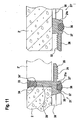
- Fig. 11 the left side is shown as section AA of Fig. 9, the right side of Fig. 11 corresponds to a neighboring plate according to the invention. Shown is initially the frame profile 21 with the edge profile 21a, on which a plate 2 rests and is thereby determined by acting as a stop web 28 in position.
- the support frame 21 is provided with openings 30, which will be explained later.
- an upper projection 25 is shown, which has a downwardly directed latching teeth 31.
- the transition region protrusion 25 in the frame profile 21a is elastically resilient, so that the projection 25 has a certain flexibility.
- a bottom plate adjacent thereto is provided, the edge structure of which corresponds to the section BB of FIG. 9.
- the plate 2 ' thus engages over the lower projection 26, so that when joining the bottom plates 21, 21', the plate 2 'comes to rest above the upper projection 25 of the edge profile 21a.
- this installation situation for the plate 2 ' is shown, in which case the lower projection 26 of the support profile 21c is below the upper projection 25 of the frame profile 21a.
- the upper projection 25 is thus enclosed on both sides. So that the upper latching projection 25 can nevertheless slide over the latching teeth, is a Distance to the plate 2 'provided so that the top of the locking projection 25 is lower than the bottom of the plate 2' and the bearing surface of the plate. 2
- the plates 2, 2 ' are held by the web 28 at a predetermined minimum distance from each other, wherein a mounted on the web 28 seal 33 seal the plates from the top.
- the seal 33 is widened wedge-shaped upward and has in the region of the shaft on to the plate 2 and 2 'extending sealing lip 34, 34' on.
- the wedge-shaped end of the seal 33 comes with the inclined surfaces for contact with correspondingly formed inclined surfaces on the plates 2, 2 'and thereby causes a seal.
- moisture such as an applied cleaning fluid
- the support frame is also provided on its underside with a receiving groove 35 in which an insulating profile 36 is inserted.
- the insulating profile 36 projects beyond the lower edge of the frame profile 21a and can have lateral compensation spaces 37, 37 'which allow deformation of the insulating profile 36 under load.
- the support profiles 21a and the stiffening ribs 22, 23 are provided with an embedded in a groove insulation profile, so that there is a good impact sound insulation.
- FIG. 12 also shows a section along the line AA, but here the arrangement of the opening 30, 30 'and the interposed support webs 38 of the support region 27 can be seen. Of particular importance is the course of the side walls of the webs 38 such that the opening 30 of the support surface for the plate to the bottom of the support frame 21 out to expand. This allows the mechanical anchoring of the plate in the support frame 21 by means of passing through the opening 30 adhesive.
- the plate, not shown, is thereby also mechanically firmly connected to the support frame 21, since a kind of dovetail connection is formed.
- the adhesive application on the upper side of the support web 38 takes place, for example, mechanically by means of a doctor blade.
- only the back of the plate may be coated with adhesive, or both. It is not always necessary to bring about a full-surface bonding. In some cases, it is sufficient to coat only partial surfaces with adhesive, wherein the adhesive may also be applied in the form of a bead of adhesive.
- thermoplastic adhesives so-called hot melts may be used, but also one- or multi-component reactive adhesives, in particular polyurethane (PU) adhesive with a slight AnFum .
- PU polyurethane
- the upper and the lower projections 25, 26 can be seen, wherein the projections 25, 26 on the support profile 21a, however, are not opposite, but are offset in the plane of the drawing by a distance, as shown in FIG is. However, here the interaction of the ratchet teeth can be seen well. It should be noted that the lower projection 26 has an elasticity to allow a sliding past the locking teeth. An additional alternative space is not provided here, since it is assumed is that the entire plate when loosening the locking connection can also be raised. Thus, a release of the latching connection is possible even if the upper latching projection would be supported directly on the underside of the plate.
- FIG. 13 shows a section of the lower right-hand corner from FIG. 9.
- Both the support profiles 21a, 21d and the reinforcing ribs 22, 23 have an insulating profile 36th which can be sharpened via a central injection point 40 in the region of the intersection point 24 into the grooves 35 provided after the support frame has been produced in a first injection process.
- the bearing surface between the edge profile 21a and the reinforcing rib 23 is provided with apertures 30, 30 ', between which the support webs 38 extend.
- Fig. 14a is again a section through the support profile 21a, 21d shown, which in turn can be seen that only the edge profile 21a is provided with the web 28, which acts as a stop for the plate, whereas the support profile 21d has no such web ,
- a particular embodiment of the seal 33 is shown.
- sealing beads 34 are provided, which project into a groove on the edge of the plate 2, 2 '.
- the groove 41 can certainly also be larger than the sealing bead 34, as long as it is ensured that at least in sections a seal is made. There is thus a sealing surface 42 available.
- connection of the plate to the support frame is produced for example by means of an adhesive technique.
- hot melt or a curable adhesive can be applied so that the adhesive passes through the conically widening openings 30 and causes a mechanical anchoring.
- a normal adhesive bond is present, so that the plate is fixed after curing of the adhesive both via the adhesive bond and on the mechanical anchoring in the manner of a dovetail connection.
- the support frame may be provided with the thermoplastic elastomer by a two-component injection molding process and the impact sound insulation seal 33 with a hard-plastic material, such as the frame itself.
- a hard-plastic material such as the frame itself.
- Polystyrene or polyurethane comes into question and as impact sound insulation a thermoplastic elastomer TPE.
- the locking teeth can also be using a single projection simply latching or as in the exemplary embodiment as a detent toothing multiple detent, so that optionally reinforceddifferenzen be compensated.
- the locking connection is designed so that when lifting the plate at the opposite edge due to the leverage
- the one-sided locking connection of the second embodiment has the advantage that the overall height compared to a connector is again significantly reduced.
- the impact sound insulation is embedded in the bearing surface, in the embodiment in the reinforcing ribs 22, 23 and the edge profiles 21a to d. This also makes it possible to achieve a low height.
- the footfall sound insulation can be designed so that in addition a slip-resistant effect is achieved.
- the bottom plate formed of plate and support frame has due to the adhesive joint increased static strength, so that the required plate thickness in the case of granite plates from previously 10 mm to 8 mm or even up to 6 mm thickness is possible. This leads to a considerable material and thus cost savings in the production of a floor covering.
- the insulating profile 36 projects beyond the underside of the edge profiles 21a-d or the reinforcing ribs 22, 23, but the underside of the support profiles or reinforcing ribs also come to rest under extreme load and thus prevent destruction of the impact sound insulation.
- the embedded in a groove impact sound insulation is therefore protected against damage under extreme load.
- the adhesive itself should be chosen so that sufficient thermal stability is achieved when using underfloor heating. When laying outdoors, the adhesive must be weather-resistant.
Landscapes
- Engineering & Computer Science (AREA)
- Architecture (AREA)
- Civil Engineering (AREA)
- Structural Engineering (AREA)
- Ceramic Engineering (AREA)
- Chemical & Material Sciences (AREA)
- Floor Finish (AREA)
- Road Paving Structures (AREA)
- Steam Or Hot-Water Central Heating Systems (AREA)
- Conveying And Assembling Of Building Elements In Situ (AREA)
Description
- Die Erfindung bezieht sich auf einem Auflagerahmen für Platten, auf eine Bodenplatte, umfassend eine Platte und diesem Auflagerahmen, und auf ein Verlegesystem, umfassend Platten und Auflagerahmen und eignet sich insbesondere für Steinzeugfliesen und Natursteinfliesen sowie Holzplatten.
- Bodenplatten werden, soweit es sich um Stein- oder Keramikfliesen handelt, in der Regel mittels eines geeigneten Klebers auf der entsprechend vorbereiteten Unterlage, z. B. auf einem Glattestrich, verlegt, wobei die Fugenbreite meist durch Einlegen von Fugenkreuzen festgelegt wird und die Fugen nachträglich ausgefugt werden müssen. Das Verlegen ist sowohl hinsichtlich der erforderlichen Werkzeuge als auch hinsichtlich der notwendigen Materialien vergleichsweise aufwendig und erfordert darüber hinaus auch ein relativ hohes handwerkliches Geschick vom Verleger. Darüber hinaus ist ein hoher Zeitbedarf erforderlich, bis der Belag begehbar ist. Ein weiterer Nachteil ist darin zu sehen, dass ein nach dieser Vorgehensweise verlegter Plattenbelag nicht ohne weiteres, d. h. nicht ohne Zerstörung der Platten entfernt werden kann.
- Bei Holzplatten, beispielsweise bei Parkett- oder Laminatplatten, wie sie für Fußbodenbeläge eingesetzt werden, ist es bekannt, an den einen beiden der sich kreuzenden Plattenseiten eine Nut und an den anderen beiden Plattenseiten eine dazu passende Feder vorzusehen. Beim Verlegen der Platten werden jeweils Platten mit korrespondierenden Nuten und Federn aneinander gestoßen und miteinander verklebt. Auch hier kann der Plattenbelag zu einem späteren Zeitpunkt nicht ohne Zerstörung der Platten entfernt werden.
- Aus der
DE 199 62 812 oderDE 200 09 717 U1 sind Steinfliesen mit einem Auflagerahmen und einer Dichtung bekannt. - Gemäß der
DE 199 62 812 A1 ist es bekannt, die Ränder von zu verlegenden Boden- und Wandplatten jeweils mit einem Randprofil zu versehen, welche mit den Platten verklebt sein können. Die Randprofil sind so ausgebildet, dass ein erster Schenkel für die Auflage der Platte und ein zweiter Schenkel zur Anlage an der umlaufenden Randfläche der Platte vorhanden ist. Darüber hinaus ist noch auf der der Platte abgewandten Seite des sich am Plattenrand erstreckenden Schenkels ein Vorsprung vorgesehen, welcher zusammen mit dem Vorsprung der benachbarten Platte für eine vorgegebene Mindestbreite der Fuge verantwortlich ist. In die Fuge, welche durch zwei spiegelsymmetrische angeordnete Randprofile gebildet wird, wird ein Abdeckprofil eingesetzt. Dieses Abdeckprofil ist über eine Verzahnung gegen Herausgleiten gesichert. An der Platte kann eine rutschfeste Dämpfungsschicht vorgesehen sein, wobei allerdings der Randbereich der Unterseite der Platte freigelassen ist, weil dort umlaufend die Randprofile angelegt sind. Die mit den Randprofilen vorkonfektionierten Platten werden auf einer Bodenfläche so ausgelegt, dass die Vorsprünge aneinander stoßen. - Gemäß der
DE 200 09 717 U1 ist es bekannt, zwischen zwei aneinander grenzenden Platten ein im wesentlichen T-förmiges Tragprofil vorzusehen, welches zwei seitliche Auflagestege zum Abstützen jeweils einer Platte und einen mittleren Halteabschnitt mit einer Aufnahmenut für eine Dichtung aufweist. Der Halteabschnitt erstreckt sich ein Stück weit entlang der Plattenkante und die Dichtung ist so ausgebildet, dass sie zur Plattenoberseite hin mehrere aufeinanderfolgende Dichtflächen bereit stellt. Zwischen der Platte und dem seitlichen Auflagesteg ist ein Dichtungsband vorgesehen, welches eventuell durch die Dichtung hindurchgetretenes Wasser am Austreten auf die Unterseite der Platte verhindert. Darüber hinaus kann im Bereich des Auflagestegs ein Führungssteg zur Bildung von Ablaufrinnen vorgesehen sein. - In der
EP 0 256 189 A1 sind Fußbodenplatten, aufweisend einen Rahmen mit ausgeformten Seitenkanten mit Eingreifelementen gegensätzlichen Geschlechts, offenbart. Dieses Dokument enthält die Merkmale des Oberbegriffes der Ansprüche 1 und 7. Der Rahmen weist eine obere und eine untere Seite auf. Die obere Seite enthält dabei Fußbodenbelagmaterial. Die Eingreifelemente sind zum Verbinden von benachbarten Seitenkanten gegensätzlichen Geschlechts ausgebildet und angeordnet. Der Rahmen ist mit einer Vielzahl von Öffnungen versehen, die sich zwischen der oberen und der unteren Seite erstrecken. Das Fußbodenbelagmaterial wird mittels Kleber durch die Öffnungen hindurch mit einer dämpfenden Schaumunterlage befestigt, die sich auf der unteren Seite befindet. An allen vier Seiten des Rahmens befinden sich Fortsätze. Das Fußbodenbelagmaterial wird durch einrastende Elemente, die sich auf der oberen Seite der Fortsätze befinden, auf der oberen Seite des Rahmens befestigt. Die Eingreifelemente gegensätzlichen Geschlechts, die sich auf der unteren Seite der Fortsätze befinden, dienen zum Verbinden benachbarter Fußbodenplatten. Dabei wirken sie in senkrechter Richtung zusammen. - Der Erfindung liegt die Aufgabe zugrunde, ein Verlegesystem anzugeben, bei dem das Verlegen der Platten relativ leicht, d. h. auch von ungeübten Personen durchgeführt werden kann. Das Verlegesystem soll insbesondere für Natursteinplatten wie Granit, Marmor usw. aber auch für Holz-, Keramik- oder auch aus anderen Werkstoffen hergestellte Platten geeignet sein. Es soll außerdem gewährleisten, dass der Belag bei Bedarf ohne Beschädigung der einzelnen Platten wieder entfernt werden kann.
- Die Erfindung besteht aus einem Auflagerahmen bzw. aus einem Bodenplatte bzw. aus einem Verlegesystem, mit der Merkmale des Anspruchs 7 bzw. 6 bzw. 1.
- Mit dem erfindungsgemäß vorgeschlagenen Verlegesystem, das Platten und Auflagerahmen umfasst, lassen sich die vorgenannten Nachteile vermeiden. Jede Platte liegt zumindest teilflächig mit ihrer Unterseite auf einem der Auflageprofile mit Auflagebereichen aufweisenden Auflagerahmen auf, wobei der Auflagerahmen einen über die Auflagefläche zur Oberseite der Platte hin vorstehenden Ansatz aufweist, welcher sich zumindest abschnittsweise an der Kante der Platte entlang in Richtung Oberseite der Platte erstreckt. Die Auflagerahmen sind miteinander verbindbar. Der Ansatz ist ein Bestandteil des Auflagerahmens und ist nur an zwei einander benachbarten Auflageprofilen vorgesehen, wohingegen die beiden anderen Auflageprofile einen Auflagebereich ohne Ansatz aufweisen. Die ersten Auflageprofile weisen mindestens einen über die Platte hinausgehenden Rastfortsatz in seitlicher Richtung auf, wobei die beiden anderen, zweiten Auflageprofile mindestens einen unterhalb der Platte in seitlichen Richtung liegenden Rastforsatz aufweisen und jeweils ein Auflageprofil mit einem anderen Auflageprofil in seitlicher Richtung zusammenwirkt.
- Im Falle von quadratischen oder rechtwinkligen Platten hat der Auflagerahmen insgesamt vier Auflageprofile, wobei durch die besondere Ausgestaltung der Verbindung ein Verschieben paralleler Reihen von verlegten Platten möglich ist. Dadurch ist es möglich, die Platten auch versetzt zu verlegen. In diesem Fall stoßen dann in einer Ecke einer Platte nicht vier Ecken zusammen, sondern es treffen zwei Ecke auf eine Seitenkante der benachbarten Plattenreihe.
- Durch das die einzelnen Fliesen gegenseitig abdichtende Fugengummi wird ein präzises, gleichbleibendes Fugenbild erreicht, das auch durch seine Dichtigkeit gegenüber Wasser überzeugt.
- Dank der Erfindung sind selbst bei der Verlegung größerer Bereiche Dehnfugen nicht mehr erforderlich, da durch die schwimmende Verlegung kein fester Kontakt zum Untergrund besteht. Die Gefahr der Rissbildung im Bodenbelag bzw. der einzelnen Platte, wie sie bei auf den Estrich verklebten Platten gegeben ist, besteht daher nicht. Darüber hinaus sind für die Verlegung keine Kleber mehr notwendig.
- Besondere Vorteile ergeben sich bei der Verlegung von hochwertigen Platten, wie Granitplatten oder ähnlichen Platten, da hier die zusätzlichen Kosten des Verlegesystems vom Stückpreis her betrachtet weniger ins Gewicht fallen und als weitaus wichtigerer Vorteil Fehler bei der Verlegung selbst bei kaum geschultem Verlegepersonal vermieden werden. Darüber hinaus sinken die Verlegungskosten beträchtlich.
- Durch die schwimmende Verlegung ist es möglich, in Altbausanierung mit Holzdielenboden ohne große Vorarbeiten den Granitboden schnell und kostengünstig auf der vorhandenen Holzkonstruktionen zu verlegen. Auch für Holzbaufertighäuser ist es mit Hilfe der Erfindung möglich, Granit und Naturstein zu verlegen.
- Das sehr häufig auftretende Problem der mangelhaften Trittschalldämmung in den vorhandenen Estrichen, bei denen oftmals als Folge einer unsachgemäßen Verlegung Schallbrücken entstehen, tritt bei Verwendung des erfindungsgemäßen Verlegesystems in Verbindung mit einer Trittschalldämmung nicht mehr auf und es wird eine optimale Dämmung gewährleistet. Dazu sind die Auflagerahmen auf ihrer Unterseite mit einer Trittschalldämmung versehen.
- Neben dem Verlegesystem ist Gegenstand der Anmeldung eine Bodenplatte, umfassend eine Platte und einen Auflagerahmen, zur Verwendung in einem Verlegesystem. Ein weiterer Gegenstand ist ein Auflagerahmen für eine Platte. Vorteilhafte Weiterbildungen sind in den jeweiligen Unteransprüchen beschrieben.
- Anhand der Zeichnung wird ein Ausführungsbeispiel der Erfindung näher erläutert. Es zeigen:
- Fig. 1
- einen vorgefertigten Rahmen zur Aufnahme einer Platte,
- Fig. 2a
- einen Ausschnitt aus einem Bodenbelag mit einer verlegten Platte,
- Fig. 2b
- einen weiteren Ausschnitt aus einem Bodenbelag mit zwei verlegten Platte,
- Fig. 3
- eine Draufsicht auf eine Ecke eines Auflagerahmens,
- Fig. 4
- einen (männlichen) Teil des Rahmenprofils im Querschnitt,
- Fig. 5
- einen (weiblichen) Teil des Rahmenprofils im Querschnitt,
- Fig. 6
- eine in den einen Teil des Rahmenprofils einsetzbare Dichtung im Querschnitt,
- Fig. 7
- eine weitere Rastverbindung im Querschnitt,
- Fig. 8
- noch eine weitere Rastverbindung im Querschnitt.
- Fig. 9
- ein weiteres Ausführungsbeispiel für einen vorgefertigten Rahmen zur Aufnahme einer Platte,
- Fig. 10
- einen Schnitt durch die Bodenplatte nach Fig. 9,
- Fig. 11
- einen weiteren Ausschnitt aus dem Bodenbelag mit zwei zu verlegenden Bodenplatten,
- Fig. 12
- eine Teilvergrößerung aus Fig. 9 mit Durchbrechungen in der Auflagefläche im Querschnitt,
- Fig. 13
- eine Teilvergrößerung aus Fig. 9 in Ansicht von unten,
- Fig. 14a
- eine Teilvergrößerung aus Fig. 9 eines ersten Auflageprofils im Querschnitt,
- Fig. 14b
- eine Teilvergrößerung aus Fig. 9 eines zweiten Auflageprofils im Querschnitt,
- Fig. 15a
- eine Variante der Gestaltung der Dichtung,
- Fig. 15b
- die Dichtung im Detail.
- Bei den dargestellten Ausführungsbeispielen wird von einem Fußbodenbelag ausgegangen, der aus einer Vielzahl von aneinander gereihten Steinplatten, z. B. Granitplatten, gebildet wird, die unter Zwischenlage meiner Abstandsfuge auf einer Unterlage, z. B. einem Rohestrich oder einem Dielenboden schwimmend verlegt werden.
- Die Figur 1 zeigt in einer schaubildlichen Darstellung einen viereckigen Rahmen 1 zur Aufnahme einer (in dieser Figur nicht dargestellten) Platte, z. B. einer Granitplatte. Der Rahmen 1 besteht aus einem Kunststoff und ist vorgefertigt; er kann aus einem einteiligen Spritzteil oder auch aus einzelnen Elementen, die aus einem Stangenprofil zusammengesetzt sind, bestehen. Als Material kann auch ein Recycling-Kunststoff verwendet werden.
- Von den vier Schenkeln 1a bis 1d des Rahmens 1 haben jeweils die beiden einen aneinander grenzenden Schenkel 1c, 1d ein Steckprofil 3 welches in Figur 4 im Querschnitt gezeigt ist. Die beiden anderen Schenkel 1a, 1b haben ein Steckprofil 4 wie in Fig. 5 im Querschnitt gezeigt. Alle vier Schenkel 1a bis 1d haben eine streifenförmige Auflage 5, auf der im verlegten Zustand eine in den Rahmen einsetzbare Platte 2 aufliegt.
- In Fig. 2a ist die Auflage einer solchen Platte 2 auf der streifenförmigen Auflage 5 mit dem Steckprofil 4 gezeigt. Die Breite der Auflage 5 beträgt bei einer Plattenbreite von 305 mm zweckmäßigerweise 20 mm.
- Der durch die Stärke (Bauhöhe) der Auflage 5 des Rahmens 1 vorgegebene Abstand von der Verlegeunterlage (Fußbodenestrich) zur aufgesetzten Platte 2 kann vorteilhafterweise zur Einlage einer Trittschalldämmung 12 benutzt werden. Die Höhe der Trittschalldämmung 12 ist dabei so zu bemessen, dass sie erst im belasteten Zustand dem besagten Abstand von der Verlegeunterlage zu Platte entspricht. Die Trittschalldämmung 12 ist vorteilhafterweise auf der Plattenunterseite aufgeklebt. Damit wird die Bildung von Rückschall, wie es aus dem Parkettbereich als Problem bekannt ist, zuverlässig vermieden.
- In Fig. 2b ist der Einbauzustand zweier Platten gezeigt, wobei jedoch die rechte der dargestellten Platten 2 zu Illustrationszwecken nach hinten versetzt ist. Die Platte 2 liegt mit ihrer Unterseite im Randbereich auf der streifenförmigen Auflage 5 auf und ist mit dieser verklebt.
- Abweichend von Fig. 2a erstreckt sich die Trittschalldämmung 12 nicht nur bis in die Nähe der Auflage 5, sondern auch noch unter dieser, so dass selbst im Bereich der Auflage 5 eine Dämmung stattfindet. Dies ist mit durchbrochenen Linien dargestellt, wobei der Bereich unterhalb der Auflage 5 mit der Bezugsziffer 13 gekennzeichnet ist.
- Sofern kleinere Unebenheiten bzw. Rauhigkeiten in der Oberfläche der Verlegeunterlage ausgeglichen werden müssen, z. B. bei einem sehr rauhen Estrich, kann es vorteilhaft sein, unter den Rahmen 1 zusätzlich noch eine nicht dargestellte nachgiebige Schaumstoffunterlage zu kleben. Diese Unterlage kann punktuell oder flächig aufgeklebt werden.
- Wie aus der Darstellung in Fig. 4 hervorgeht, weist das Steckprofil 3 der Schenkel 1c und 1d einen senkrecht nach oben gerichteten Ansatz 6 auf, an deren beiden Seiten im verlegten Zustand die Platten 2 anliegen. Der Ansatz 6 ist mit einer Nut 7 versehen, in die eine in Fig. 6 im Querschnitt gezeigte Gummidichtung 8 eingelegt wird. Bei Bedarf kann die Dichtung 8 auch im Nutbereich mit dem Ansatz 6 des Schenkels verklebt sein, sodass ein Herausarbeiten sicher vermieden wird. Darüber hinaus ist vorgesehen, die Dichtung 8 in einer der farblichen Gestaltung der Platten angepassten Farbe herzustellen. Es ist daher nicht erforderlich, dass der Rahmen farblich auf die Platten abgestimmt ist.
- Die Gummidichtung 8 ist pilzförmig ausgeführt, wobei der Stiel 8a der Dichtung 8 so ausgebildet ist, dass er in die Nut 7 des Ansatzes 6 paßt. Der Hut 8b ist vorzugsweise trapezförmig ausgebildet und in der Höhe so ausgeführt, dass seine Oberkante im verlegten Zustand etwa mit der Oberkante einer in den Rahmen eingesetzten Platte 2 abschließt, wie in Fig. 2b dargestellt.
- Die Breite der Gummidichtung 8 ist zumindest zum oberen Ende hin größer bemessen als die Breite des Ansatzes 6, wodurch im verlegten Zustand der Platten die Gummidichtung zusammen gepreßt wird und eine Spaltabdichtung erreicht wird. An den Ecken, also im Kreuzungspunkt der Platten, ist die Gummidichtung 8 im Winkel von 90° auf Gehrung geschnitten (Fig. 3), so dass auch im Kreuzungspunkt eine Dichtung erzielt wird.
- Das Steckprofil 3 (Fig. 4) enthält einen Fortsatz 9, der mit einer dazu passend ausgebildeten Rastnut 11 im Steckprofil 4 (Figur 5) korrespondiert. Die beiden Steckprofile 3 und 4 bilden so eine Steckrastung mit dem sich mehrere Rahmen leicht zusammenstecken und auch später wieder leicht trennen lassen. Damit ein problemloses Zusammenstecken der Teile ohne Zuschnitt vor Ort erreicht wird, sind bei jedem Rahmen die Fortsätze 9 mit den Rastnocken 10 gegenüber der Außenkante des Rahmens um ein Maß X zurückgesetzt.
- Jede zu verlegende Platte 2 ist mit einem Rahmen wie in Figur 1 gezeigt versehen. Vorzugsweise sind die Rahmen auf der Unterseite der Platten aufgeklebt, so dass Platte und Rahmen eine Einheit bilden. Das Verkleben hat zudem noch den Vorteil, dass die Platten im Plattenverbund fest fixiert sind und ein "Herausarbeiten" der Platten auch bei langzeitigem Begehen des fertigen Belages vermieden wird.
- Zum Verlegen werden die Platten mit den daran angeklebten Rahmen auf die vorbereitete Unterlage auf die der Plattenbelag aufgebracht werden soll (hier Fußbodenestrich) gelegt und so aneinander gesetzt, dass jeweils die Schenkel mit den Rastnuten 11 an die Schenkel mit den Rastnocken 10 zu liegen kommen. Durch Zusammenfügen (Einklicken) der Teile wird eine mechanische Verbindung hergestellt die bei Bedarf später wieder lösbar ist. Beim Zusammenfügen wird außerdem, wie bereits erwähnt, die Gummidichtung 8 soweit zusammen gepreßt, dass eine gewisse Vorspannung erzeugt wird. Mit der Vorspannung wird eine ausreichende Dichtung gegen Eindringen von Schmutz und Feuchtigkeit sichergestellt. Außerdem lassen sich Toleranzen beim Verlegen der Platten ausgleichen.
- In Fig. 7 ist eine weitere Rastverbindung dargestellt, bei der der den Schenkel 1c überragende Rastnocken 10 an seiner Oberseite und an seiner Unterseite Hinterschneidungen bereitstellt, welche in eine ebenfalls zwei Hinterschneidungen aufweisende Nut 11 am aufnehmenden Schenkel 1a einrasten. Beim Eindringen des Rastnockens in die Rastnut wird diese aufgespreizt und schnappt nach dem vollständigen Einführen und der Anlage der Seitenkante des Schenkels 1a an der Seitenkante bzw. dem Ansatz 6 des Schenkels 1c wieder zusammen. Die Materialelastizität ist dabei so ausgewählt, dass dies zerstörungsfrei möglich ist.
- In Fig. 8 ist die Rastverbindung im Bereich eines Vorsprungs 14 und einer Nut 15 selbst hinterschneidungsfrei ausgebildet, sodass hier nur eine Führung stattfindet. Die mechanische Sicherung erfolgt über einen Rastnocken 10 an der Unterseite des Vorsprungs 14 und eine Rastvertiefung 11 in der Oberfläche der unteren Seitenwand der Nut 11. Dabei kann zur Montageerleichterung eine Einfügeschräge 16 vorgesehen sein, die gestrichelt angedeutet ist.
- In den Fig. 4, 5, 7 und 8 wird besonders deutlich, dass das weibliche Steckprofil 4 das männliche Steckprofil 3 auf der Unterseite ein Stück weit, nämlich um die Breite des Ansatzes 6, untergreift.
- In Fig. 9 ist eine weitere Ausführungsform der Erfindung gezeigt. Ein Auflagerahmen 21 besteht hier zusätzlich zu den am Rand liegenden Randprofilen 21a, b, c, d aus Versteifungsrippen 22, 23, von denen eine erste Gruppe 22 parallel zu den Seiten und eine zweite Gruppe 23 in Diagonalrichtung liegt. Die Rippen 22, 23 kreuzen sich, so dass Kreuzungspunkte 24 entstehen. Diese Kreuzungspunkte können von unterschiedlicher Größe sein.
- An den Randprofilen 21a bis d sind obere und untere Vorsprünge 25, 26 ausgebildet, welche jeweils eine Hälfte einer Rastverbindung darstellen, nämlich die obere Hälfte bzw. die untere Hälfte. Dies wird nachfolgend noch näher erläutert. Jeder von Rippen den Randprofilen 21a-d und von den 22, 23 begrenzte Feld Auflagebereich 27 weist Durchbrechungen auf, angedeutet durch die Punktierung, deren Funktion später erläutert wird.
- In Fig. 10 ist ein Querschnitt durch den Auflagerahmen gemäß Fig. 9 gezeigt, wobei die Seitenprofile 21b, 21d im Randbereich zu erkennen sind. Darüber hinaus ist der Verlauf des Stegs 28 zu erkennen. Der Steg 28 erstreckt sich ausgehend von den Profilen 21a bis d über fast die gesamte Länge bzw. Breite des Auflagerahmens 21, jedoch nur an zwei einander benachbarten Seiten. In Fig. 9 ist dies zu erkennen durch den am Profil 21a angeordnete Steg 28 und den am benachbarten Profil 21b angeordnete Steg 29.
- In Fig. 10 sind ebenfalls die Durchbrechungen 30 sowie die innen liegenden Rippen 22 dargestellt. Zu erkennen sind weiterhin ein oberer und unterer Teil 25, 26 einer Rastverbindung.
- In Fig. 11 ist die linke Seite als Schnitt AA aus Fig. 9 dargestellt, die rechte Seite der Fig. 11 entspricht einer Nachbarplatte gemäß der Erfindung. Dargestellt ist zunächst das Rahmenprofil 21 mit dem Randprofil 21a, auf welchem eine Platte 2 aufliegt und dabei durch den als Anschlag wirkenden Steg 28 in ihrer Lage festgelegt ist.
- Der Auflagerahmen 21 ist mit Durchbrechungen 30 versehen, die später erläutert werden.
- Auf der Außenseite des Auflagerahmens 21 ist ein oberer Vorsprung 25 gezeigt, welcher eine nach unten gerichtete Rastverzahnung 31 besitzt. Der Übergangsbereich Vorsprungs 25 in das Rahmenprofil 21a ist elastisch federnd ausgebildet, so dass der Vorsprung 25 eine gewisse Nachgiebigkeit aufweist.
- Im rechten Teil der Fig. 11 ist eine dazu benachbarte Bodenplatte vorgesehen, deren Randaufbau dem Schnitt BB aus Fig. 9 entspricht. Die Platte 2' liegt auf dem Randprofil 21c auf, welches einen unteren Vorsprung 26 mit einer Rastverzahnung 32 besitzt. Die Platte 2' übergreift dabei auch den unteren Vorsprung 26, so dass beim Zusammenfügen der Bodenplatten 21, 21' die Platte 2' oberhalb des oberen Vorsprungs 25 des Randprofils 21a zu liegen kommt. Auf der linken Seite der Fig. 11 ist diese Einbausituation für die Platte 2' dargestellt, wobei dann der untere Vorsprung 26 des Auflageprofils 21c unterhalb des oberen Vorsprungs 25 des Rahmenprofils 21a liegt. Der obere Vorsprung 25 ist somit beidseitig umschlossen. Damit der obere Rastvorsprung 25 gleichwohl über die Rastverzahnung gleiten kann, ist ein Abstand zu der Platte 2' vorgesehen, so dass die Oberseite des Rastvorsprungs 25 tiefer liegt als die Unterseite der Platte 2' bzw. die Auflagefläche der Platte 2.
- Die Platten 2, 2' werden über den Steg 28 in einem vorgegebenen minimalen Abstand zu einander gehalten, wobei eine auf dem Steg 28 angebrachte Dichtung 33 die Platten gegenüber der Oberseite abdichten. Dazu ist die Dichtung 33 nach oben keilförmig verbreitert und weist im Bereich des Schaftes eine sich zu der Platte 2 bzw. 2' erstreckende Dichtlippe 34, 34' auf. Beim Zusammenfügen der Platten kommt das keilförmige Ende der Dichtung 33 mit den Schrägflächen zur Anlage an entsprechend ausgebildete Schrägflächen an den Platten 2, 2' und bewirkt hierdurch eine Abdichtung. Tritt gleichwohl Feuchtigkeit, etwa eine aufgebrachte Reinigungsflüssigkeit, durch diese Dichtflächen hindurch, verhindern die Dichtlippen 34, 34' ein weiteres Durchlecken nach unten.
- Der Auflagerahmen ist darüber hinaus an seiner Unterseite mit einer Aufnahmenut 35 versehen, in welcher ein Dämmprofil 36 eingelegt ist. Das Dämmprofil 36 steht über den unteren Rand des Rahmenprofils 21a hervor und kann über seitliche Ausgleichsräume 37, 37' verfügen, welche eine Verformung des Dämmprofils 36 unter Last ermöglichen. Außer den Auflageprofilen 21a sind auch die Versteifungsrippen 22, 23 mit einem in einer Nut eingebetteten Dämmprofil versehen, so dass es zu einer guten Trittschalldämmung kommt.
- In Fig. 12 ist ebenfalls ein Schnitt längs der Linie AA dargestellt, wobei hier jedoch die Anordnung der Durchbrechung 30, 30' und die dazwischen liegenden Auflagestege 38 des Auflagebereichs 27 zu erkennen sind. Von besonderer Bedeutung ist der Verlauf der Seitenwände der Stege 38 derart, dass sich die Durchbrechung 30 von der Auflagefläche für die Platte zur Unterseite des Auflagerahmens 21 hin erweitern. Dies ermöglicht die mechanische Verankerung der Platte in dem Auflagerahmen 21 mittels durch die Durchbrechung 30 hindurchtretenden Klebstoffes. Die nicht dargestellte Platte wird hierdurch auch mechanisch fest mit dem Auflagerahmen 21 verbunden, da eine Art Schwalbenschwanz-Verbindung entsteht.
- Zwischen der Unterseite der Auflagestege 38 bzw. der Durchbrechungen 30 und der Unterseite des Auflagestegs 21a ist ein Abstand vorhanden. Der Klebeauftrag auf die Oberseite des Auflagestegs 38 erfolgt beispielsweise maschinell mittels einer Rakel. Alternativ dazu kann auch nur die Rückseite der Platte mit Kleber beschichtet sein, oder beides. Es ist dabei nicht immer erforderlich, eine vollflächige Verklebung herbeizuführen. In manchen Fällen reicht es aus, lediglich Teilflächen mit Klebstoff zu beschichten, wobei der Klebstoff auch in Form einer Klebstoffraupe aufgebracht sein kann.
- Als Klebstoff können thermoplastische Klebstoffe, sogenannte Hotmelts zur Anwendung kommen, aber auch ein-oder mehrkomponentige reaktive Klebstoffe, insbesondere Polyurethan(PU)-Kleber mit leichtem Anschäumverhalten.
- Auch in Fig. 12 sind die oberen bzw. die unteren Vorsprünge 25, 26 zu erkennen, wobei die Vorsprünge 25, 26 am Auflageprofil 21a sich jedoch nicht gegenüberliegen, sondern in die Zeichenebene hinein um einen Abstand versetzt sind, wie aus Fig. 9 ersichtlich ist. Allerdings lässt sich hier das Zusammenspiel der Rastverzahnung gut erkennen. An dieser Stelle sei darauf hingewiesen, dass auch der untere Vorsprung 26 eine Elastizität aufweist, um ein Vorbeigleiten der Rastverzahnung zu ermöglichen. Ein zusätzlicher Ausweichraum ist hier jedoch nicht vorgesehen, da davon ausgegangen wird, dass die gesamte Platte beim Lösen der Rastverbindung auch angehoben werden kann. Damit ist ein Lösen der Rastverbindung selbst dann möglich, wenn der obere Rastvorsprung sich unmittelbar an der Unterseite der Platte abstützen würde.
- In Fig. 13 ist ein Ausschnitt der rechten unteren Ecke aus Fig. 9 dargestellt. Zu erkennen ist hier zum einen der Verlauf der Randprofile 21a, 21d sowie der überstehende Steg 28 und eine diagonal verlaufende Verstärkungsrippe 23 sowie zum Auflageprofil 21a parallel verlaufende Verstärkungsrippe 22. Sowohl die Auflageprofile 21a, 21d als auch die Verstärkungsrippen 22, 23 weisen ein Dämmprofil 36 auf, welches über einen zentralen Einspritzpunkt 40 im Bereich des Kreuzungspunktes 24 in die dafür vorgesehenen Nuten 35 eingespitzt werden kann, nachdem der Auflagerahmen in einem ersten Spritzprozess hergestellt wurde. Die Auflagefläche zwischen der dem Randprofil 21a und der Verstärkungsrippe 23 ist mit Durchbrechungen 30, 30' versehen, zwischen denen sich die Auflagestege 38 erstrecken.
- In Fig. 14a ist nochmals ein Schnitt durch die Auflageprofil 21a, 21d dargestellt, wobei wiederum zu erkennen ist, dass ausschließlich das Randprofil 21a mit dem Steg 28 versehen ist, welcher als Anschlag für die Platte wirkt, wohingegen das Auflageprofil 21d keinen derartigen Steg aufweist.
- In Fig. 15a ist eine besondere Ausgestaltung der Dichtung 33 gezeigt. Anstelle der in Fig. 11 dargestellten Dichtlippen sind Dichtwülste 34 vorgesehen, welche in eine Nut an der Kante der Platte 2, 2' hinein ragen. In der Detailansicht gemäß Fig. 15b ist zu erkennen, dass die Nut 41 durchaus auch größer als der Dichtwulst 34 sein kann, solange sichergestellt ist, dass zumindest abschnittsweise eine Abdichtung hergestellt ist. Es ist somit eine Dichtfläche 42 vorhanden.
- Wie bereits erwähnt, wird die Verbindung der Platte mit dem Auflagerahmen beispielsweise über eine Klebetechnik hergestellt. Dabei kann Heißkleber oder eine aushärtbare Klebemasse so aufgebracht werden, dass die Klebemasse durch die sich konisch erweiternden Durchbrechungen 30 hindurch tritt und eine mechanische Verankerung bewirkt. Auf der Auflagefläche zwischen den Durchbrechungen ist eine normale Klebeverbindung vorhanden, so dass die Platte nach dem Aushärten des Klebstoffs sowohl über die Klebeverbindung als auch über die mechanische Verankerung nach Art einer Schwalbenschwanz-Verbindung befestigt ist.
- Der Auflagerahmen kann über ein Zweikomponenten-Spritzgußverfahren mit dem thermoplastischen Elastomer und für die Dichtung 33 für die Trittschalldämmung 36 versehen werden, wobei für den Rahmen selbst ein hartplastisches Material wie z.B. Polystyrol oder Polyurethan in Frage kommt und als Trittschalldämmung ein thermoplastisches Elastomer TPE.
- Die Rastverzahnung kann darüber hinaus unter Verwendung eines einzigen Vorsprungs einfach rastend oder wie im Ausführungsbeispiel als Rastverzahnung mehrfach rastend sein, so dass gegebenenfalls Maßdifferenzen ausgleichbar sind. Die Rastverbindung ist dabei so auszubilden, dass beim Anheben der Platte an der gegenüberliegenden Kante aufgrund der Hebelwirkung
- ein Lösen möglich ist. Bei einer reinen Zugbeanspruchung flächig verlegter Platten soll ein Lösen hingegen nur nach Überschreiten der gebrauchsüblichen Belastungen möglich sein.
- Die einseitige Rastverbindung des zweiten Ausführungsbeispiels hat den Vorteil, dass die Bauhöhe gegenüber einer Steckverbindung nochmals deutlich verringert ist.
- Die Trittschalldämmung ist in die Auflagefläche eingelassen, im Ausführungsbeispiel in die Verstärkungsrippen 22, 23 und die Randprofile 21a bis d. Auch hierdurch lässt sich eine geringe Bauhöhe erreichen. Die Trittschalldämmung kann so ausgebildet sein, dass zusätzlich eine rutschhemmende Wirkung erzielt wird.
- Die aus Platte und Auflagerahmen gebildete Bodenplatte weist aufgrund der Klebeverbindung eine erhöhte statische Festigkeit auf, so dass die erforderliche Plattendicke im Fall von Granitplatten von bisher 10 mm auf 8 mm oder sogar bis auf 6 mm Dicke möglich ist. Dies führt zu einer beträchtlichen Material- und damit Kosteneinsparung bei der Herstellung eines Bodenbelags.
- Wie vorstehend bereits erwähnt steht das Dämmprofil 36 über die Unterseite der Randprofile 21a - d bzw. der Verstärkungsrippen 22, 23 hervor, wobei die Unterseite der Auflageprofile bzw. Verstärkungsrippen jedoch bei extremer Belastung ebenfalls zur Auflage gelangen und so eine Zerstörung der Trittschalldämmung verhindern. Die in eine Nut eingelassene Trittschalldämmung ist daher gegen eine Beschädigung bei extremer Belastung geschützt.
- Der Kleber selbst ist so auszuwählen, dass bei Verwendung von Fußbodenheizungen eine hinreichende thermische Stabilität gegeben ist. Bei einer Verlegung im Außenbereich muß der Kleber witterungsstabil sein.
-
- 1
- Auflagerahmen
- 1a, 1b
- Schenkel mit Rastnut
- 1c, 1d
- Schenkel mit Ansatz und Rastnocke
- 2
- Platte
- 2'
- Platte
- 3
- Steckprofil
- 4
- Steckprofil
- 5
- Auflage
- 6
- Ansatz
- 7
- Nut
- 8
- Dichtung
- 8a
- Stiel
- 8b
- Hut
- 9
- Fortsatz
- 10
- Rastnocke
- 11
- Rastnut, Rastvertiefung
- 12
- Trittschalldämmung
- 13
- Bereich der Trittschalldämmung unter der Auflage 5
- 14
- Vorsprung
- 15
- Nut
- 16
- Fügeschräge
- 21
- Auflagerahmen
- 21a-d
- Randprofile
- 22
- Versteifungsrippen (Stützstege?)
- 23
- Versteifungsrippen
- 24
- Kreuzungspunkte
- 25
- Vorsprung
- 26
- Vorsprung
- 27
- Auflagebereich
- 28
- Steg
- 29
- Steg
- 30
- Durchbrechungen
- 30'
- Durchbrechungen
- 31
- Rastverzahnung
- 33
- Dichtung
- 34
- Dichtlippe
- 34'
- Dichtlippe
- 35
- Aufnahmenut
- 36
- Dämmprofil
- 37,37'
- Ausgleichsräume
- 38
- Auflagestege
- 40
- Einspritzpunkt
- 41
- Nut
- 42
- Dichtfläche
Claims (15)
- Verlegesystem, umfassend Platten (2) und Auflagerahmen (21),zur Erstellung eines Bodenbelages aus Platten, insbesondere Steinfliesen, wobei jede Platte (2) zumindest teilflächig mit ihrer Unterseite auf einem der Randprofile (21a, 21b, 21c, 21d) mit Auflagebereichen aufweisenden Auflagerahmen (21) aufliegt, wobei der Auflagerahmen (21) einen über die Auflagefläche zur Oberseite der Platte hin vorstehenden Steg (28) aufweist, welcher sich zumindest abschnittsweise an der Kante der Platte (2) entlang in Richtung Oberseite der Platte (2) erstreckt und wobei die Auflagerahmen (21) miteinander verbindbar sind, dadurch gekennzeichnet, dass der Steg (28) ein Bestandteil des Auflagerahmens (21) ist, dass der Steg (28) nur an zwei einander benachbarten Auflageprofilen (21a, 21b) vorgesehen ist, wohingegen die beiden anderen Auflageprofile (21c, 21d) einen Auflagebereich ohne Steg aufweisen, von denen die einen Randprofile (21a, 21b) mindestens einen über die Platte (2) hinausgehenden Rastfortsatz (25, 26) mit seitlicher Ausrichtung aufweisen, wobei die beiden anderen Auflageprofile (21c, 21d) mindestens einen unterhalb der Platte (2) liegenden Rastfortsatz (25, 26) mit seitlicher Ausrichtung aufweisen und wobei jeweils ein Auflageprofil (21a, 21b) mit einem anderen Auflageprofil (21c, 21d) in seitlicher Richtung zusammenwirkt.
- Verlegesystem nach Anspruch 1, dadurch gekennzeichnet, dass an dem Ansatz ein Dichtungsprofil (28) ausgebildet ist, welches sich an der Kante der Platte (2) entlang in Richtung Oberseite der Platte (2) erstreckt.
- Verlegesystem nach Anspruch 1 oder 2, dadurch gekennzeichnet, dass der Auflagerahmen (21) und die Platte (2) eine Einheit bildet und vorzugsweise miteinander verklebt sind.
- Verlegesystem nach einem der Ansprüche 1 bis 3,
dadurch gekennzeichnet, dass der Auflagerahmen (21) an seiner Unterseite mit einer Trittschalldämmung (36) versehen ist. - Verlegesystem nach Anspruch 4, dadurch gekennzeichnet, dass der Auflagerahmen unter dem Auflagebereich eine Trittschalldämmung (36) aufweist.
- Bodenplatte, umfassend eine Platte (2) und einen Auflagerahmen (21), nach einem der Ansprüche 7 bis 15.
- Auflagerahmen (21) für Platten (2) zur Verwendung in einem Verlegesystem, umfassend Randprofile (21a, 21b, 21c, 21d) mit Auflagebereichen für Platten (2), einen über die Auflagefläche zur Oberseite der Platte hin vorstehenden Steg (28), welcher sich zumindest abschnittsweise an der Kante der Platte (2) entlang in Richtung Oberseite der Platte (2) erstreckt und wobei die Auflagerahmen (21) miteinander verbindbar sind,
dadurch gekennzeichnet, dass der Steg (28) ein Bestandteil des Auflagerahmens (21) ist, dass der Steg (28) nur an zwei einander benachbarten Auflageprofilen (21a, 21b) vorgesehen ist, wohingegen die beiden anderen Auflageprofile (21c, 21d) einen Auflagebereich ohne Steg aufweisen von denen die einen Randprofile (21a, 21b) mindestens einen über die Platte (2) hinausgehenden Rastfortsatz (25, 26) mit seitlicher Ausrichtung aufweisen, wobei die beiden anderen Auflageprofile (21c, 21d) mindestens einen unterhalb der Platte (2) liegenden Rastfortsatz (25, 26) mit seitlicher Ausrichtung aufweisen und jeweils ein Auflageprofil (21a, 21b) mit einem anderen Auflageprofil (21c, 21d) in seitlicher Richtung zusammenwirkt. - Auflagerahmen (21) nach Anspruch 7, dadurch gekennzeichnet, dass eine an dem Steg (28) befestigte Dichtung (8), insbesondere aus gummielastischem Material vorgesehen ist.
- Auflagerahmen (21) nach Anspruch 7 oder 8, gekennzeichnet durch eine in dem Ansatz (6) vorgesehene Nut (7), in welche die Dichtung (8) einlegbar ist.
- Auflagerahmen (21) nach einem der Ansprüche 7 bis 9,
dadurch gekennzeichnet, dass der Auflagerahmen an seiner Unterseite mit einem Dämmprofil (36) versehen ist, wobei das Dämmprofil (36) insbesondere in einer Nut (35) aufgenommen ist. - Auflagerahmen (21) nach einem der Ansprüche 7 bis 10,
dadurch gekennzeichnet, dass der Auflagerahmen (21) Verstärkungsrippen (22, 23) und eine Auflagefläche (27) mit Durchbrechungen (30, 30') aufweist und dass die Verstärkungsrippen (22, 23) an ihrer Unterseite mit einer Nut (35) zur Aufnahme eines Dämmprofils (36) versehen sind. - Auflagerahmen (21) nach Anspruch 11, dadurch gekennzeichnet, dass die Durchbrechungen (30, 30') in der Auflagefläche sich von der Platte ausgehend konisch erweitern.
- Auflagerahmen (21) nach einem der Ansprüche 7 bis 12,
dadurch gekennzeichnet, dass der Auflagerahmen (21) aus einem Stück vorgefertigt ist. - Auflagerahmen (21) nach einem der Ansprüche 7 bis 12,
dadurch gekennzeichnet, dass der Auflagerahmen (21) aus zusammengesetzten Profilen (21a - d), vorzugsweise Strangpressprofilen, gebildet ist. - Auflagerahmen (21) nach Anspruch 8 oder 10 sowie einem der Ansprüche 9 oder 11 bis 14, dadurch gekennzeichnet, dass die Dichtung (8) einerseits und das Dämmprofil (36) andererseits stofflich mit dem Rahmen verbunden sind, insbesondere durch Anspritzen.
Applications Claiming Priority (5)
| Application Number | Priority Date | Filing Date | Title |
|---|---|---|---|
| DE10158215A DE10158215B4 (de) | 2001-11-28 | 2001-11-28 | Verlegesystem für Bodenplatten |
| DE10158215 | 2001-11-28 | ||
| DE20214622U DE20214622U1 (de) | 2001-11-28 | 2002-09-20 | Verlegesystem für Bodenplatten |
| DE20214622U | 2002-09-20 | ||
| PCT/DE2002/004023 WO2003040491A1 (de) | 2001-11-28 | 2002-10-28 | Verlegesystem für bodenplatten |
Publications (2)
| Publication Number | Publication Date |
|---|---|
| EP1490565A1 EP1490565A1 (de) | 2004-12-29 |
| EP1490565B1 true EP1490565B1 (de) | 2007-09-26 |
Family
ID=26010668
Family Applications (1)
| Application Number | Title | Priority Date | Filing Date |
|---|---|---|---|
| EP02779182A Expired - Lifetime EP1490565B1 (de) | 2001-11-28 | 2002-10-28 | Verlegesystem für bodenplatten |
Country Status (10)
| Country | Link |
|---|---|
| US (1) | US7197855B2 (de) |
| EP (1) | EP1490565B1 (de) |
| CN (1) | CN1309920C (de) |
| AT (1) | ATE374294T1 (de) |
| AU (1) | AU2002342548A1 (de) |
| DE (2) | DE50210994D1 (de) |
| ES (1) | ES2246746T1 (de) |
| HK (1) | HK1078115A1 (de) |
| RU (1) | RU2305164C2 (de) |
| WO (1) | WO2003040491A1 (de) |
Families Citing this family (105)
| Publication number | Priority date | Publication date | Assignee | Title |
|---|---|---|---|---|
| GB0202310D0 (en) * | 2002-02-01 | 2002-03-20 | Kingspan Access Floors Ltd | Improvements in and relating to floor panels |
| WO2005003574A1 (de) * | 2003-07-07 | 2005-01-13 | Poschacher Natursteinwerke Gmbh & Co Kg | Platte zur verlegung auf böden, wänden, decken, fassaden oder dgl |
| US7181891B2 (en) * | 2003-09-08 | 2007-02-27 | Quiet Solution, Inc. | Acoustical sound proofing material and methods for manufacturing same |
| AT414253B (de) * | 2003-10-01 | 2006-10-15 | Lenhard Backhaus Hugo Dipl Ing | Bodenbelag aus belagsplatten |
| AT414147B (de) * | 2003-10-01 | 2006-09-15 | Lenhard Backhaus Hugo Dipl Ing | Belag aus belagsplatten |
| DE10355788B4 (de) * | 2003-11-26 | 2008-02-07 | Meyer, Hans | Platte zur Verwendung in einem Verlegesystem, insbesondere zur Herstellung eines Bodenbelags sowie Verfahren zur Herstellung derselben |
| EP1710369A1 (de) * | 2004-01-27 | 2006-10-11 | Sispel Suministro E Instalaciones, S.L. | Modulare plattierung für pflasterung |
| US7698859B2 (en) * | 2004-08-20 | 2010-04-20 | Vicente-Francisco Sansano Marti | Removable surface covering |
| US8495851B2 (en) * | 2004-09-10 | 2013-07-30 | Serious Energy, Inc. | Acoustical sound proofing material and methods for manufacturing same |
| ATE481537T1 (de) | 2004-10-05 | 2010-10-15 | Nicolaas Albertus Heyns | Trägerelement, modulares fliesenelement, system von verriegelungsmechanismen und verfahren zum verlegen von fliesen |
| US7921965B1 (en) | 2004-10-27 | 2011-04-12 | Serious Materials, Inc. | Soundproof assembly and methods for manufacturing same |
| US7610731B1 (en) * | 2005-01-10 | 2009-11-03 | Comc, Llc | Snap together floor structure |
| US7798287B1 (en) * | 2005-01-20 | 2010-09-21 | Serious Materials, Inc. | Acoustical ceiling panels |
| ES2259544B1 (es) * | 2005-02-07 | 2007-09-16 | Taulell, S.A. | Suelo desmontable. |
| US7743568B1 (en) * | 2005-02-25 | 2010-06-29 | Montgomery Mars | Tile system and method |
| DE102005019638B4 (de) | 2005-04-26 | 2007-02-08 | Kronotec Ag | Verfahren zur Herstellung eines Fußbodenelementes |
| EP1934417B1 (de) | 2005-10-03 | 2012-05-23 | Tarkett SAS | Bausatz für Flächenverkleidung |
| US7543417B2 (en) | 2005-10-04 | 2009-06-09 | Comc, Llc | Modular flooring assemblies |
| CN101313114B (zh) * | 2005-10-04 | 2013-10-02 | Comc有限责任公司 | 模块化地板组件 |
| AU2011250780B2 (en) * | 2005-10-04 | 2014-07-10 | Comc, Llc | Modular flooring assemblies |
| US8029881B2 (en) * | 2005-11-04 | 2011-10-04 | Serious Energy, Inc. | Radio frequency wave reducing material and methods for manufacturing same |
| US20070227094A1 (en) * | 2006-03-14 | 2007-10-04 | Larach Oscar | Modular raintank |
| ES1062734Y (es) * | 2006-04-17 | 2006-10-16 | Golden Decking S L | Placa perfeccionada para la configuracion de suelos |
| DE102006024857A1 (de) * | 2006-05-24 | 2007-11-29 | Guido Schulte | Belag für Böden, Wände oder Decken |
| US20080078135A1 (en) * | 2006-10-03 | 2008-04-03 | Mcintosh Jonathan | Grout member for modular flooring assemblies |
| US20100088982A1 (en) * | 2006-11-20 | 2010-04-15 | Alessandro Fogli | System and a method of dry laying of covering elements for floors or walls and a support for said system |
| US20080171179A1 (en) * | 2007-01-11 | 2008-07-17 | Quiet Solution, Llc | Low embodied energy wallboards and methods of making same |
| EP1953308A1 (de) * | 2007-01-31 | 2008-08-06 | Sika Technology AG | Verfahren zum Anbringen eines Bodenbelages auf einen Boden |
| US7984600B2 (en) * | 2007-02-02 | 2011-07-26 | Mohawk Carpet Corporation | Groutless tile system and method for making the same |
| US20120090258A1 (en) * | 2007-02-02 | 2012-04-19 | Mohawk Carpet Corporation | Groutless tile system and method for making the same |
| WO2008109961A1 (en) * | 2007-03-15 | 2008-09-18 | Innvotech Pty Ltd | A tiling apparatus |
| SG146580A1 (en) * | 2007-03-29 | 2008-10-30 | Promociones Brial S L | Assembly system for floor and/or wall tiles |
| US7987645B2 (en) * | 2007-03-29 | 2011-08-02 | Serious Materials, Inc. | Noise isolating underlayment |
| US9388568B2 (en) * | 2007-04-06 | 2016-07-12 | Pacific Coast Building Products, Inc. | Acoustical sound proofing material with improved fracture characteristics and methods for manufacturing same |
| US7883763B2 (en) | 2007-04-12 | 2011-02-08 | Serious Materials, Inc. | Acoustical sound proofing material with controlled water-vapor permeability and methods for manufacturing same |
| US8424251B2 (en) * | 2007-04-12 | 2013-04-23 | Serious Energy, Inc. | Sound Proofing material with improved damping and structural integrity |
| US8181738B2 (en) * | 2007-04-24 | 2012-05-22 | Serious Energy, Inc. | Acoustical sound proofing material with improved damping at select frequencies and methods for manufacturing same |
| US8397864B2 (en) * | 2007-04-24 | 2013-03-19 | Serious Energy, Inc. | Acoustical sound proofing material with improved fire resistance and methods for manufacturing same |
| US10174499B1 (en) | 2007-05-01 | 2019-01-08 | Pacific Coast Building Products, Inc. | Acoustical sound proofing material for architectural retrofit applications and methods for manufacturing same |
| US20080286609A1 (en) * | 2007-05-15 | 2008-11-20 | Surace Kevin J | Low embodied energy wallboards and methods of making same |
| US20100101457A1 (en) * | 2007-05-25 | 2010-04-29 | Surace Kevin J | Low embodied energy sheathing panels and methods of making same |
| US20080302043A1 (en) * | 2007-06-08 | 2008-12-11 | Kelly Gibson | Panelling system formed from rectangular panels |
| US20080302053A1 (en) * | 2007-06-08 | 2008-12-11 | Kelly Gibson | Panelling system formed from panels defined by tongue and groove strips |
| US20090000245A1 (en) * | 2007-06-28 | 2009-01-01 | Tinianov Brandon D | Methods of manufacturing acoustical sound proofing material |
| US9387649B2 (en) * | 2007-06-28 | 2016-07-12 | Pacific Coast Building Products, Inc. | Methods of manufacturing acoustical sound proofing materials with optimized fracture characteristics |
| US7908818B2 (en) * | 2008-05-08 | 2011-03-22 | Serious Materials, Inc. | Methods of manufacturing acoustical sound proofing materials with optimized fracture characteristics |
| US7799410B2 (en) * | 2007-06-30 | 2010-09-21 | Serious Materials, Inc. | Acoustical sound proofing material with improved damping at select frequencies and methods for manufacturing same |
| US7914914B2 (en) * | 2007-06-30 | 2011-03-29 | Serious Materials, Inc. | Low embodied energy sheathing panels with optimal water vapor permeance and methods of making same |
| US7707792B2 (en) * | 2007-08-06 | 2010-05-04 | Premark Rwp Holdings, Inc. | Flooring system with grout line |
| US8337993B2 (en) * | 2007-11-16 | 2012-12-25 | Serious Energy, Inc. | Low embodied energy wallboards and methods of making same |
| ES1066639Y (es) * | 2007-11-21 | 2008-05-16 | Alaves Montajes Y Realizacione | Loseta para recubrimiento de superficies |
| US20090133348A1 (en) * | 2007-11-22 | 2009-05-28 | Kelly Gibson | Flooring system |
| GB2459460A (en) * | 2008-04-23 | 2009-10-28 | Andrew Nicholas Perla | Prefabricated patio panels |
| KR101050399B1 (ko) * | 2008-05-20 | 2011-07-19 | 현대산업개발 주식회사 | 복수의 방수시트를 이용한 방수공법 |
| RU2506381C2 (ru) * | 2008-07-29 | 2014-02-10 | Клик'н Уок АГ | Система облицовки поверхностей |
| ITVI20080204A1 (it) * | 2008-08-29 | 2010-02-28 | Foster Allestimenti S R L | Pedana di supporto perfezionata per la realizzazione di strutture architettoniche |
| CN201314111Y (zh) * | 2008-10-31 | 2009-09-23 | 赖英光 | 一种新型塑料地垫 |
| US8230654B2 (en) | 2009-06-10 | 2012-07-31 | Comc, Llc | Medallion insert for modular flooring assemblies |
| US8782989B2 (en) * | 2009-06-11 | 2014-07-22 | Comc, Llc | Narrow lined modular flooring assemblies |
| NL2003559C2 (nl) * | 2009-09-28 | 2011-03-29 | Easy Sanitairy Solutions Bv | Afdichting. |
| KR101316300B1 (ko) | 2009-11-24 | 2013-10-08 | (주)엘지하우시스 | 복합패널 및 그 제조 방법 |
| HUE044231T2 (hu) * | 2009-12-22 | 2019-10-28 | Flooring Ind Ltd Sarl | Fedõpanelok gyártására szolgáló eljárás |
| EP2369090B1 (de) * | 2010-03-16 | 2015-10-07 | Fligo Flooring Innovation Group AB | Modulare Fußbodensubstrat |
| BE1019331A5 (nl) | 2010-05-10 | 2012-06-05 | Flooring Ind Ltd Sarl | Vloerpaneel en werkwijzen voor het vervaardigen van vloerpanelen. |
| US8925275B2 (en) | 2010-05-10 | 2015-01-06 | Flooring Industries Limited, Sarl | Floor panel |
| BE1019501A5 (nl) | 2010-05-10 | 2012-08-07 | Flooring Ind Ltd Sarl | Vloerpaneel en werkwijze voor het vervaardigen van vloerpanelen. |
| DE102010017189A1 (de) * | 2010-06-01 | 2011-12-01 | Novo-Tech Gmbh & Co. Kg | Unterkonstruktionselement für einen Bodenbelag |
| PL2602096T3 (pl) | 2010-08-05 | 2014-05-30 | Butech Building Tech S A | Proces wytwarzania elementów pokrycia podłogowego wymiennego i pokrycie podłogowe wymienne |
| IT1403088B1 (it) * | 2010-11-10 | 2013-10-04 | Tenax Spa | Elemento per pavimentazione in materiale plastico a struttura reticolare, procedimento per la produzione dello stesso ed uso dell elemento di pavimentazione |
| IT1403352B1 (it) * | 2010-12-23 | 2013-10-17 | Newfloor S R L | Pavimentazione flottante autoposante a secco |
| DE102011004893A1 (de) | 2011-03-01 | 2012-09-06 | Hans Meyer | Verbundplatte, Verbindungsstück und Verlegesystem sowie Verfahren zur Herstellung einer Verbundplatte |
| ITMI20111052A1 (it) | 2011-06-10 | 2012-12-11 | Planium S R L | Sistema di pavimentazione |
| ITMI20111053A1 (it) * | 2011-06-10 | 2012-12-11 | Planium S R L | Piastra per pavimentazione e metodo per ottenerla |
| KR20130059247A (ko) * | 2011-11-28 | 2013-06-05 | 유니손 코포레이션 | 블록 |
| US8887462B2 (en) * | 2012-08-21 | 2014-11-18 | Ali TATARI | Prefabricated tile system with modular backing board |
| US20140144092A1 (en) * | 2012-11-27 | 2014-05-29 | John G. Benz | System and apparatus for installation of tile floor |
| ITTV20130006A1 (it) * | 2013-01-18 | 2014-07-19 | New Tile Di Girotto Ambra | Struttura di piastrella componibile |
| CA2842448C (en) | 2013-03-08 | 2016-01-19 | Pavestone, LLC | Load-bearing paver and method of installation |
| EP2989269B1 (de) * | 2013-04-24 | 2020-10-07 | MXF Holding GmbH | Verlegeplatte insbesondere für fussböden |
| TWM459265U (zh) * | 2013-04-25 | 2013-08-11 | zhe-an Cai | 石材高架地板 |
| USD791346S1 (en) | 2015-10-21 | 2017-07-04 | Pavestone, LLC | Interlocking paver |
| US10583588B2 (en) | 2013-06-21 | 2020-03-10 | Pavestone, LLC | Manufactured retaining wall block with improved false joint |
| US20140377016A1 (en) | 2013-06-21 | 2014-12-25 | Pavestone, LLC | Retaining wall block system with modulating heights, widths, and included angles |
| EP3036385A4 (de) | 2013-09-16 | 2017-05-10 | Connor Sports Flooring LLC | Fussbodenfläche mit integrierter ineinandergreifender kunststoffbasis |
| USD737468S1 (en) | 2014-05-07 | 2015-08-25 | Pavestone, LLC | Front face of a retaining wall block |
| US9637871B2 (en) * | 2014-06-18 | 2017-05-02 | Newpark Mats & Integrated Services Llc | Load-supporting surface with actively connected gap seals and related apparatus and methods |
| US9809982B2 (en) | 2014-09-15 | 2017-11-07 | Connor Sport Court International, Llc | Suspended modular flooring panel |
| US10012341B2 (en) * | 2015-08-06 | 2018-07-03 | Lined Products Llc | Universal precast base system |
| WO2017044739A1 (en) | 2015-09-10 | 2017-03-16 | Comc, Llc | Modular flooring assemblies |
| ITUB20154618A1 (it) * | 2015-10-12 | 2017-04-12 | Dps Floor S R L | Attrezzatura modulare per pavimentazioni in legno. |
| US10626622B2 (en) * | 2016-07-06 | 2020-04-21 | Super-Click Technology Co., Ltd. | Assembled floor unit |
| CA2988547C (en) | 2016-12-15 | 2021-01-26 | Certainteed Gypsum, Inc. | Plaster boards and methods for making them |
| USD854711S1 (en) | 2017-04-05 | 2019-07-23 | Oshkosh Floor Designs Acquisition, LLC | Modular flooring tile |
| WO2019067607A2 (en) | 2017-09-26 | 2019-04-04 | Certainteed Gypsum, Inc. | PLASTER PLATES HAVING INTERNAL LAYERS AND METHODS OF MAKING SAME |
| CN111433421B (zh) | 2017-09-28 | 2022-02-15 | 瑟登帝石膏公司 | 灰泥板及其制备方法 |
| WO2019068008A1 (en) | 2017-09-30 | 2019-04-04 | Certainteed Gypsum, Inc. | FILLED PLASTER PLATES AND METHODS OF MAKING SAME |
| DE102018000253A1 (de) * | 2018-01-15 | 2019-07-18 | Dieter Preissing | Belagplatte, insbesondere zur Verwendung als Bodenbelag oder als Wandverkleidung |
| KR101907111B1 (ko) * | 2018-02-14 | 2018-10-11 | 이경준 | 레벨 조절 및 충격 흡수가 가능한 우드블럭 모듈 |
| NL2025283B1 (en) * | 2020-04-06 | 2021-10-25 | I4F Licensing Nv | Tile panel, surface covering of a multitude of such tile panels for a floor, ceiling or wall surface. |
| CN111997238B (zh) * | 2020-08-28 | 2021-08-24 | 中冶建工集团有限公司 | 一种干挂面板安装结构 |
| CN112609602A (zh) * | 2020-12-03 | 2021-04-06 | 济南华锐铁路机械制造有限公司 | 一种高铁站台防滑地面铺装结构及其铺装方法 |
| CZ2021144A3 (cs) * | 2021-03-23 | 2022-05-25 | Novotek Limited | Podlahová dlaždice |
| US11840847B2 (en) * | 2021-05-27 | 2023-12-12 | Robert N. PERRINE | Interconnected modular frames for groutless setting of hard tiles |
| NL2028782B1 (en) | 2021-07-19 | 2023-01-25 | Jan Benninga Sievert | Method of laying a modular surface covering system and underlayment tile |
| USD1037491S1 (en) | 2021-12-14 | 2024-07-30 | Pavestone, LLC | Wall block |
Citations (1)
| Publication number | Priority date | Publication date | Assignee | Title |
|---|---|---|---|---|
| WO1999041814A1 (en) * | 1998-02-13 | 1999-08-19 | Interface, Inc. | Modular flooring systems and methods |
Family Cites Families (39)
| Publication number | Priority date | Publication date | Assignee | Title |
|---|---|---|---|---|
| US464850A (en) * | 1891-12-08 | Hydrocarbon-burner | ||
| US2303745A (en) * | 1939-02-21 | 1942-12-01 | M B Farrin Lumber Co | Manufacture of single matted flooring panel |
| US3016316A (en) * | 1958-12-22 | 1962-01-09 | Arnold P Olson | Laminated board construction |
| US3339329A (en) * | 1965-05-18 | 1967-09-05 | Edward T Berg | Arrangement for securing panels to the surface of a roof or wall |
| US3553921A (en) * | 1967-07-04 | 1971-01-12 | Rasmus Breistein | Wall construction, particularly for load-bearing walls |
| US3504472A (en) * | 1967-09-12 | 1970-04-07 | Andrew B Clement | Portable patio floor structure |
| US3535844A (en) * | 1969-10-30 | 1970-10-27 | Glaros Products Inc | Structural panels |
| US3723233A (en) * | 1971-07-15 | 1973-03-27 | P Bourke | Marble faced wall panels and method of making same |
| DE2246778A1 (de) | 1972-09-23 | 1974-03-28 | Otto Kreibaum | Holzpflaster |
| US4067155A (en) * | 1975-08-28 | 1978-01-10 | Grefco, Inc. | Sealing system |
| DE3036339A1 (de) | 1980-09-26 | 1982-05-27 | Villeroy & Boch Keramische Werke Kg, 6642 Mettlach | Verfahren zum verlegen von belagtafeln aus durch vorverfugung miteinander verbundenen fliesen sowie wand- oder bodentafel |
| CA1191304A (en) * | 1983-02-23 | 1985-08-06 | Richard A. Morrison | Mat module with ramp strip |
| US4640850A (en) | 1983-04-18 | 1987-02-03 | Technomarmi Maiera S.P.A. | Composite slab incorporating a sheet of marble or similar natural stone, for the formation of facings for building, interior decoration and the like |
| US4590731A (en) * | 1983-08-10 | 1986-05-27 | Degooyer Lonnie C | Tile reinforcing grid |
| US4550543A (en) * | 1984-01-09 | 1985-11-05 | Marcello Valenzano | Construction forms |
| JPS6153958A (ja) * | 1984-08-20 | 1986-03-18 | 株式会社 サアミ | タイル状繊維床材敷設方法 |
| US4664955A (en) * | 1986-03-21 | 1987-05-12 | Swiss Aluminium Ltd. | Natural stone facing composite laminate |
| GB8612355D0 (en) * | 1986-05-21 | 1986-06-25 | Aristodimou E | Stone tiles |
| EP0256189B1 (de) * | 1986-08-20 | 1991-10-09 | William Alan Lonie | Elementeböden |
| US4931331A (en) * | 1988-04-05 | 1990-06-05 | Owens Charles R | Laminated tile product, method for producing the same and method for installing the same |
| US5418036A (en) * | 1991-11-25 | 1995-05-23 | Fukuyi Chemical Industry Co., Ltd. | Tile application backing material and tile application execution method |
| US5417020A (en) * | 1992-08-12 | 1995-05-23 | Dobija; Michael J. | Wall system providing an array of individual panels |
| FR2721053B1 (fr) * | 1994-06-10 | 1996-08-02 | Fabrication Diffusion | Installation de pose de panneaux sans fixation visible, notamment pour l'habillage de murs et/ou la mise en place d'étagères ou d'équipements suspendus et outil pour la mise en place d'une telle installation. |
| EP0782553B1 (de) * | 1994-09-22 | 2003-04-16 | MÜLLER-HARTBURG, Johannes | Bodenfliese und verfahren zu ihrer herstellung |
| US5611185A (en) * | 1995-04-19 | 1997-03-18 | Thomas B. Van Wyk | Surface mounted grid system and process of installation |
| US6230385B1 (en) * | 1996-11-01 | 2001-05-15 | Premark Rwp Holdings, Inc. | Molding affixed with wedged divider track |
| US5899040A (en) * | 1997-09-08 | 1999-05-04 | Cerrato; Dominic | Flexible interlocking wall system |
| US6694689B1 (en) * | 1998-02-13 | 2004-02-24 | Interface, Inc. | Modular flooring systems and methods |
| US6247286B1 (en) * | 1998-08-03 | 2001-06-19 | Nicolaas Albertus Heyns | Modular structural element |
| US6021615A (en) * | 1998-11-19 | 2000-02-08 | Brown; Arthur J. | Wood flooring panel |
| TW407667U (en) * | 1999-11-25 | 2000-10-01 | Chen Shing Sheng | Bonding structure of boards supporting bracket |
| AU4743800A (en) | 1999-12-23 | 2001-07-09 | Hamberger Industriewerke Gmbh | Joint |
| US6332733B1 (en) * | 1999-12-23 | 2001-12-25 | Hamberger Industriewerke Gmbh | Joint |
| DE19962812A1 (de) | 1999-12-23 | 2001-06-28 | Norton Sipro Gmbh | Verfahren und Vorrichtung zum Schließen von Fugen |
| DE20009717U1 (de) | 2000-05-30 | 2000-11-16 | Mehlhose Hans Dietrich | Fugenprofil |
| CN2439490Y (zh) * | 2000-06-28 | 2001-07-18 | 陈义钊 | 插接式活动地板撑架 |
| US6647684B1 (en) * | 2001-11-05 | 2003-11-18 | High Mountain Flooring, Inc. | Flooring system |
| US6862855B1 (en) * | 2003-04-16 | 2005-03-08 | Dave G. Milum | Structural assembly for decks, walkways, patios, and docks |
| US6990777B2 (en) * | 2003-04-29 | 2006-01-31 | Jiri Poliacek | Tile installation system |
-
2002
- 2002-10-28 DE DE50210994T patent/DE50210994D1/de not_active Expired - Lifetime
- 2002-10-28 AT AT02779182T patent/ATE374294T1/de active
- 2002-10-28 RU RU2004120069/03A patent/RU2305164C2/ru not_active IP Right Cessation
- 2002-10-28 EP EP02779182A patent/EP1490565B1/de not_active Expired - Lifetime
- 2002-10-28 WO PCT/DE2002/004023 patent/WO2003040491A1/de active IP Right Grant
- 2002-10-28 CN CNB028276264A patent/CN1309920C/zh not_active Expired - Fee Related
- 2002-10-28 ES ES02779182T patent/ES2246746T1/es active Pending
- 2002-10-28 AU AU2002342548A patent/AU2002342548A1/en not_active Abandoned
- 2002-10-28 DE DE10295140T patent/DE10295140D2/de not_active Expired - Lifetime
-
2004
- 2004-01-08 US US10/752,591 patent/US7197855B2/en not_active Expired - Lifetime
-
2005
- 2005-11-09 HK HK05110007A patent/HK1078115A1/xx not_active IP Right Cessation
Patent Citations (1)
| Publication number | Priority date | Publication date | Assignee | Title |
|---|---|---|---|---|
| WO1999041814A1 (en) * | 1998-02-13 | 1999-08-19 | Interface, Inc. | Modular flooring systems and methods |
Also Published As
| Publication number | Publication date |
|---|---|
| RU2004120069A (ru) | 2005-06-27 |
| RU2305164C2 (ru) | 2007-08-27 |
| ES2246746T1 (es) | 2006-03-01 |
| ATE374294T1 (de) | 2007-10-15 |
| US7197855B2 (en) | 2007-04-03 |
| CN1309920C (zh) | 2007-04-11 |
| WO2003040491A1 (de) | 2003-05-15 |
| CN1617966A (zh) | 2005-05-18 |
| HK1078115A1 (en) | 2006-03-03 |
| US20040139679A1 (en) | 2004-07-22 |
| AU2002342548A1 (en) | 2003-05-19 |
| EP1490565A1 (de) | 2004-12-29 |
| DE10295140D2 (de) | 2004-12-23 |
| DE50210994D1 (de) | 2007-11-08 |
Similar Documents
| Publication | Publication Date | Title |
|---|---|---|
| EP1490565B1 (de) | Verlegesystem für bodenplatten | |
| DE69434094T2 (de) | Holz- oder Laminatfussbodensystem mit einer Vielzahl von Fussbodenpaneelen | |
| DE60015949T2 (de) | BAUSATZ FüR SCHWIMMENDEN FUSSBODEN | |
| DE10158215B4 (de) | Verlegesystem für Bodenplatten | |
| EP1913213A1 (de) | Flächenbündiges dehnungsprofil | |
| WO2006084300A1 (de) | Dichtungsprofil für fugen zwischen belagsplatten | |
| EP0828037A2 (de) | Abschlussprofil für mit Fliesen verlegte Balkone, Terrassen o.dgl. | |
| EP2425755B1 (de) | Duschtasse | |
| DE20107338U1 (de) | Flexibles Bodenbelagsträgersystem | |
| DE202008002361U1 (de) | Plattenbelag zur Anordnung an einer Wand, einer Decke oder einem Boden | |
| EP1930524A2 (de) | Bodenplatte und damit gebildeter Verbund | |
| EP2845965B1 (de) | Befestigung von Bohlen an einer Unterkonstruktion | |
| DE202004004107U1 (de) | Belag, bestehend aus einzelnen Platten aus mineralischem Material | |
| DE102007054173A1 (de) | Plattenkörper für Bauzwecke | |
| DE10237076A1 (de) | Plattenverband aus Platten aus einem Gipswerkstoff und Verfahren zum Herstellen eines Plattenverbandes | |
| DE10055354B4 (de) | Plattenelement | |
| WO2012017060A2 (de) | Flächenelastischer boden und montagemodul | |
| EP0198157A2 (de) | Bewegungsfugenleiste aus Kunststoffmaterial, insbesondere für die Randfuge einer Fussbodenkonstruktion | |
| DE10347199A1 (de) | Beheizbares Fußbodenelement mit Oberflächenschicht | |
| DE20215223U1 (de) | Fußboden aus einzelnen Elementen | |
| WO2019137824A1 (de) | Anordnung zur herstellung einer wandverkleidung oder eines bodenbelags | |
| EP3748103B1 (de) | Bodenbelag mit mindestens einem verbindungselement | |
| DE10302961B4 (de) | Wandabschlussleiste | |
| EP1760219B1 (de) | Bodenaufbausystem für Fliesenbeläge | |
| WO2004076775A1 (de) | Beläge aus belagsplatten |
Legal Events
| Date | Code | Title | Description |
|---|---|---|---|
| PUAI | Public reference made under article 153(3) epc to a published international application that has entered the european phase |
Free format text: ORIGINAL CODE: 0009012 |
|
| 17P | Request for examination filed |
Effective date: 20040707 |
|
| AK | Designated contracting states |
Kind code of ref document: A1 Designated state(s): AT BE BG CH CY CZ DE DK EE ES FI FR GB GR IE IT LI LU MC NL PT SE SK TR |
|
| AX | Request for extension of the european patent |
Extension state: AL LT LV MK RO SI |
|
| 17Q | First examination report despatched |
Effective date: 20051104 |
|
| GRAP | Despatch of communication of intention to grant a patent |
Free format text: ORIGINAL CODE: EPIDOSNIGR1 |
|
| GRAS | Grant fee paid |
Free format text: ORIGINAL CODE: EPIDOSNIGR3 |
|
| GRAA | (expected) grant |
Free format text: ORIGINAL CODE: 0009210 |
|
| AK | Designated contracting states |
Kind code of ref document: B1 Designated state(s): AT BE BG CH CY CZ DE DK EE ES FI FR GB GR IE IT LI LU MC NL PT SE SK TR |
|
| REG | Reference to a national code |
Ref country code: GB Ref legal event code: FG4D Free format text: NOT ENGLISH |
|
| REG | Reference to a national code |
Ref country code: CH Ref legal event code: EP |
|
| REF | Corresponds to: |
Ref document number: 50210994 Country of ref document: DE Date of ref document: 20071108 Kind code of ref document: P |
|
| REG | Reference to a national code |
Ref country code: IE Ref legal event code: FG4D Free format text: LANGUAGE OF EP DOCUMENT: GERMAN |
|
| PG25 | Lapsed in a contracting state [announced via postgrant information from national office to epo] |
Ref country code: FI Free format text: LAPSE BECAUSE OF FAILURE TO SUBMIT A TRANSLATION OF THE DESCRIPTION OR TO PAY THE FEE WITHIN THE PRESCRIBED TIME-LIMIT Effective date: 20070926 |
|
| NLV1 | Nl: lapsed or annulled due to failure to fulfill the requirements of art. 29p and 29m of the patents act | ||
| GBV | Gb: ep patent (uk) treated as always having been void in accordance with gb section 77(7)/1977 [no translation filed] | ||
| BERE | Be: lapsed |
Owner name: MEYER, HANS Effective date: 20071031 |
|
| PG25 | Lapsed in a contracting state [announced via postgrant information from national office to epo] |
Ref country code: NL Free format text: LAPSE BECAUSE OF FAILURE TO SUBMIT A TRANSLATION OF THE DESCRIPTION OR TO PAY THE FEE WITHIN THE PRESCRIBED TIME-LIMIT Effective date: 20070926 Ref country code: ES Free format text: LAPSE BECAUSE OF FAILURE TO SUBMIT A TRANSLATION OF THE DESCRIPTION OR TO PAY THE FEE WITHIN THE PRESCRIBED TIME-LIMIT Effective date: 20080106 Ref country code: GR Free format text: LAPSE BECAUSE OF FAILURE TO SUBMIT A TRANSLATION OF THE DESCRIPTION OR TO PAY THE FEE WITHIN THE PRESCRIBED TIME-LIMIT Effective date: 20071227 |
|
| REG | Reference to a national code |
Ref country code: IE Ref legal event code: FD4D |
|
| PG25 | Lapsed in a contracting state [announced via postgrant information from national office to epo] |
Ref country code: PT Free format text: LAPSE BECAUSE OF FAILURE TO SUBMIT A TRANSLATION OF THE DESCRIPTION OR TO PAY THE FEE WITHIN THE PRESCRIBED TIME-LIMIT Effective date: 20080226 Ref country code: SK Free format text: LAPSE BECAUSE OF FAILURE TO SUBMIT A TRANSLATION OF THE DESCRIPTION OR TO PAY THE FEE WITHIN THE PRESCRIBED TIME-LIMIT Effective date: 20070926 Ref country code: CZ Free format text: LAPSE BECAUSE OF FAILURE TO SUBMIT A TRANSLATION OF THE DESCRIPTION OR TO PAY THE FEE WITHIN THE PRESCRIBED TIME-LIMIT Effective date: 20070926 Ref country code: MC Free format text: LAPSE BECAUSE OF NON-PAYMENT OF DUE FEES Effective date: 20071031 |
|
| PG25 | Lapsed in a contracting state [announced via postgrant information from national office to epo] |
Ref country code: SE Free format text: LAPSE BECAUSE OF FAILURE TO SUBMIT A TRANSLATION OF THE DESCRIPTION OR TO PAY THE FEE WITHIN THE PRESCRIBED TIME-LIMIT Effective date: 20071226 |
|
| EN | Fr: translation not filed | ||
| PG25 | Lapsed in a contracting state [announced via postgrant information from national office to epo] |
Ref country code: DK Free format text: LAPSE BECAUSE OF FAILURE TO SUBMIT A TRANSLATION OF THE DESCRIPTION OR TO PAY THE FEE WITHIN THE PRESCRIBED TIME-LIMIT Effective date: 20070926 |
|
| PLBE | No opposition filed within time limit |
Free format text: ORIGINAL CODE: 0009261 |
|
| STAA | Information on the status of an ep patent application or granted ep patent |
Free format text: STATUS: NO OPPOSITION FILED WITHIN TIME LIMIT |
|
| 26N | No opposition filed |
Effective date: 20080627 |
|
| PG25 | Lapsed in a contracting state [announced via postgrant information from national office to epo] |
Ref country code: BE Free format text: LAPSE BECAUSE OF NON-PAYMENT OF DUE FEES Effective date: 20071031 |
|
| PG25 | Lapsed in a contracting state [announced via postgrant information from national office to epo] |
Ref country code: FR Free format text: LAPSE BECAUSE OF FAILURE TO SUBMIT A TRANSLATION OF THE DESCRIPTION OR TO PAY THE FEE WITHIN THE PRESCRIBED TIME-LIMIT Effective date: 20080704 Ref country code: IE Free format text: LAPSE BECAUSE OF FAILURE TO SUBMIT A TRANSLATION OF THE DESCRIPTION OR TO PAY THE FEE WITHIN THE PRESCRIBED TIME-LIMIT Effective date: 20070926 |
|
| PG25 | Lapsed in a contracting state [announced via postgrant information from national office to epo] |
Ref country code: GB Free format text: LAPSE BECAUSE OF FAILURE TO SUBMIT A TRANSLATION OF THE DESCRIPTION OR TO PAY THE FEE WITHIN THE PRESCRIBED TIME-LIMIT Effective date: 20070926 |
|
| PG25 | Lapsed in a contracting state [announced via postgrant information from national office to epo] |
Ref country code: EE Free format text: LAPSE BECAUSE OF FAILURE TO SUBMIT A TRANSLATION OF THE DESCRIPTION OR TO PAY THE FEE WITHIN THE PRESCRIBED TIME-LIMIT Effective date: 20070926 |
|
| PG25 | Lapsed in a contracting state [announced via postgrant information from national office to epo] |
Ref country code: CY Free format text: LAPSE BECAUSE OF FAILURE TO SUBMIT A TRANSLATION OF THE DESCRIPTION OR TO PAY THE FEE WITHIN THE PRESCRIBED TIME-LIMIT Effective date: 20070926 |
|
| PG25 | Lapsed in a contracting state [announced via postgrant information from national office to epo] |
Ref country code: BG Free format text: LAPSE BECAUSE OF FAILURE TO SUBMIT A TRANSLATION OF THE DESCRIPTION OR TO PAY THE FEE WITHIN THE PRESCRIBED TIME-LIMIT Effective date: 20071226 Ref country code: LU Free format text: LAPSE BECAUSE OF NON-PAYMENT OF DUE FEES Effective date: 20071028 |
|
| PG25 | Lapsed in a contracting state [announced via postgrant information from national office to epo] |
Ref country code: TR Free format text: LAPSE BECAUSE OF FAILURE TO SUBMIT A TRANSLATION OF THE DESCRIPTION OR TO PAY THE FEE WITHIN THE PRESCRIBED TIME-LIMIT Effective date: 20070926 |
|
| REG | Reference to a national code |
Ref country code: CH Ref legal event code: NV Representative=s name: FREI PATENTANWALTSBUERO AG Ref country code: CH Ref legal event code: PUE Owner name: NFS NEW FLOORING SYSTEMS AG Free format text: MEYER, HANS#RHEINFELDSTRASSE 57#68063 LUDWIGSHAFEN (DE) -TRANSFER TO- NFS NEW FLOORING SYSTEMS AG#HELVETIASTRASSE 51#3005 BERN (CH) |
|
| PG25 | Lapsed in a contracting state [announced via postgrant information from national office to epo] |
Ref country code: IT Free format text: LAPSE BECAUSE OF NON-PAYMENT OF DUE FEES Effective date: 20071031 |
|
| REG | Reference to a national code |
Ref country code: DE Ref legal event code: R081 Ref document number: 50210994 Country of ref document: DE Owner name: CLICK'N WALK AG, CH Free format text: FORMER OWNER: MEYER, HANS, 67063 LUDWIGSHAFEN, DE Effective date: 20110216 |
|
| REG | Reference to a national code |
Ref country code: CH Ref legal event code: PUE Owner name: CLICK'N WALK AG Free format text: NFS NEW FLOORING SYSTEMS AG#HELVETIASTRASSE 51#3005 BERN (CH) -TRANSFER TO- CLICK'N WALK AG#HELVETIASTRASSE 51#3005 BERN (CH) |
|
| REG | Reference to a national code |
Ref country code: DE Ref legal event code: R082 Ref document number: 50210994 Country of ref document: DE Representative=s name: OSTERTAG & PARTNER, PATENTANWAELTE, DE Effective date: 20120906 Ref country code: DE Ref legal event code: R082 Ref document number: 50210994 Country of ref document: DE Representative=s name: OSTERTAG & PARTNER PATENTANWAELTE, DE Effective date: 20120906 Ref country code: DE Ref legal event code: R082 Ref document number: 50210994 Country of ref document: DE Representative=s name: OSTERTAG & PARTNER, PATENTANWAELTE MBB, DE Effective date: 20120906 Ref country code: DE Ref legal event code: R081 Ref document number: 50210994 Country of ref document: DE Owner name: CLICK'N WALK AG, CH Free format text: FORMER OWNER: NFS NEW FLOORING SYSTEMS AG, BERN, CH Effective date: 20120906 |
|
| REG | Reference to a national code |
Ref country code: AT Ref legal event code: HC Ref document number: 374294 Country of ref document: AT Kind code of ref document: T Owner name: CLICK'N WALK AG, CH Effective date: 20121003 |
|
| PGFP | Annual fee paid to national office [announced via postgrant information from national office to epo] |
Ref country code: DE Payment date: 20151022 Year of fee payment: 14 Ref country code: CH Payment date: 20151007 Year of fee payment: 14 |
|
| PGFP | Annual fee paid to national office [announced via postgrant information from national office to epo] |
Ref country code: AT Payment date: 20151022 Year of fee payment: 14 |
|
| REG | Reference to a national code |
Ref country code: DE Ref legal event code: R119 Ref document number: 50210994 Country of ref document: DE |
|
| REG | Reference to a national code |
Ref country code: CH Ref legal event code: PL |
|
| REG | Reference to a national code |
Ref country code: AT Ref legal event code: MM01 Ref document number: 374294 Country of ref document: AT Kind code of ref document: T Effective date: 20161028 |
|
| PG25 | Lapsed in a contracting state [announced via postgrant information from national office to epo] |
Ref country code: DE Free format text: LAPSE BECAUSE OF NON-PAYMENT OF DUE FEES Effective date: 20170503 Ref country code: CH Free format text: LAPSE BECAUSE OF NON-PAYMENT OF DUE FEES Effective date: 20161031 Ref country code: LI Free format text: LAPSE BECAUSE OF NON-PAYMENT OF DUE FEES Effective date: 20161031 |
|
| PG25 | Lapsed in a contracting state [announced via postgrant information from national office to epo] |
Ref country code: AT Free format text: LAPSE BECAUSE OF NON-PAYMENT OF DUE FEES Effective date: 20161028 |