EP1487047A2 - Batterie - Google Patents
Batterie Download PDFInfo
- Publication number
- EP1487047A2 EP1487047A2 EP04013471A EP04013471A EP1487047A2 EP 1487047 A2 EP1487047 A2 EP 1487047A2 EP 04013471 A EP04013471 A EP 04013471A EP 04013471 A EP04013471 A EP 04013471A EP 1487047 A2 EP1487047 A2 EP 1487047A2
- Authority
- EP
- European Patent Office
- Prior art keywords
- group
- anode
- chemical formula
- metallic salt
- light metallic
- Prior art date
- Legal status (The legal status is an assumption and is not a legal conclusion. Google has not performed a legal analysis and makes no representation as to the accuracy of the status listed.)
- Granted
Links
Images

Classifications
-
- H—ELECTRICITY
- H01—ELECTRIC ELEMENTS
- H01M—PROCESSES OR MEANS, e.g. BATTERIES, FOR THE DIRECT CONVERSION OF CHEMICAL ENERGY INTO ELECTRICAL ENERGY
- H01M10/00—Secondary cells; Manufacture thereof
- H01M10/05—Accumulators with non-aqueous electrolyte
-
- H—ELECTRICITY
- H01—ELECTRIC ELEMENTS
- H01M—PROCESSES OR MEANS, e.g. BATTERIES, FOR THE DIRECT CONVERSION OF CHEMICAL ENERGY INTO ELECTRICAL ENERGY
- H01M10/00—Secondary cells; Manufacture thereof
- H01M10/05—Accumulators with non-aqueous electrolyte
- H01M10/054—Accumulators with insertion or intercalation of metals other than lithium, e.g. with magnesium or aluminium
-
- H—ELECTRICITY
- H01—ELECTRIC ELEMENTS
- H01M—PROCESSES OR MEANS, e.g. BATTERIES, FOR THE DIRECT CONVERSION OF CHEMICAL ENERGY INTO ELECTRICAL ENERGY
- H01M10/00—Secondary cells; Manufacture thereof
- H01M10/05—Accumulators with non-aqueous electrolyte
- H01M10/052—Li-accumulators
-
- H—ELECTRICITY
- H01—ELECTRIC ELEMENTS
- H01M—PROCESSES OR MEANS, e.g. BATTERIES, FOR THE DIRECT CONVERSION OF CHEMICAL ENERGY INTO ELECTRICAL ENERGY
- H01M10/00—Secondary cells; Manufacture thereof
- H01M10/05—Accumulators with non-aqueous electrolyte
- H01M10/056—Accumulators with non-aqueous electrolyte characterised by the materials used as electrolytes, e.g. mixed inorganic/organic electrolytes
- H01M10/0564—Accumulators with non-aqueous electrolyte characterised by the materials used as electrolytes, e.g. mixed inorganic/organic electrolytes the electrolyte being constituted of organic materials only
- H01M10/0566—Liquid materials
- H01M10/0568—Liquid materials characterised by the solutes
-
- H—ELECTRICITY
- H01—ELECTRIC ELEMENTS
- H01M—PROCESSES OR MEANS, e.g. BATTERIES, FOR THE DIRECT CONVERSION OF CHEMICAL ENERGY INTO ELECTRICAL ENERGY
- H01M10/00—Secondary cells; Manufacture thereof
- H01M10/05—Accumulators with non-aqueous electrolyte
- H01M10/058—Construction or manufacture
-
- H—ELECTRICITY
- H01—ELECTRIC ELEMENTS
- H01M—PROCESSES OR MEANS, e.g. BATTERIES, FOR THE DIRECT CONVERSION OF CHEMICAL ENERGY INTO ELECTRICAL ENERGY
- H01M10/00—Secondary cells; Manufacture thereof
- H01M10/05—Accumulators with non-aqueous electrolyte
- H01M10/056—Accumulators with non-aqueous electrolyte characterised by the materials used as electrolytes, e.g. mixed inorganic/organic electrolytes
- H01M10/0564—Accumulators with non-aqueous electrolyte characterised by the materials used as electrolytes, e.g. mixed inorganic/organic electrolytes the electrolyte being constituted of organic materials only
- H01M10/0565—Polymeric materials, e.g. gel-type or solid-type
-
- H—ELECTRICITY
- H01—ELECTRIC ELEMENTS
- H01M—PROCESSES OR MEANS, e.g. BATTERIES, FOR THE DIRECT CONVERSION OF CHEMICAL ENERGY INTO ELECTRICAL ENERGY
- H01M2300/00—Electrolytes
- H01M2300/0017—Non-aqueous electrolytes
- H01M2300/0025—Organic electrolyte
-
- H—ELECTRICITY
- H01—ELECTRIC ELEMENTS
- H01M—PROCESSES OR MEANS, e.g. BATTERIES, FOR THE DIRECT CONVERSION OF CHEMICAL ENERGY INTO ELECTRICAL ENERGY
- H01M4/00—Electrodes
- H01M4/02—Electrodes composed of, or comprising, active material
- H01M4/13—Electrodes for accumulators with non-aqueous electrolyte, e.g. for lithium-accumulators; Processes of manufacture thereof
- H01M4/134—Electrodes based on metals, Si or alloys
-
- Y—GENERAL TAGGING OF NEW TECHNOLOGICAL DEVELOPMENTS; GENERAL TAGGING OF CROSS-SECTIONAL TECHNOLOGIES SPANNING OVER SEVERAL SECTIONS OF THE IPC; TECHNICAL SUBJECTS COVERED BY FORMER USPC CROSS-REFERENCE ART COLLECTIONS [XRACs] AND DIGESTS
- Y02—TECHNOLOGIES OR APPLICATIONS FOR MITIGATION OR ADAPTATION AGAINST CLIMATE CHANGE
- Y02E—REDUCTION OF GREENHOUSE GAS [GHG] EMISSIONS, RELATED TO ENERGY GENERATION, TRANSMISSION OR DISTRIBUTION
- Y02E60/00—Enabling technologies; Technologies with a potential or indirect contribution to GHG emissions mitigation
- Y02E60/10—Energy storage using batteries
Definitions
- the present invention relates to a battery comprising a cathode, an anode, and an electrolyte.
- a battery As a secondary battery coverable of obtaining a high energy density, a battery, wherein a lithium alloy is used for an anode has been developed (for example, refer to Japanese Unexamined Patent Application Publication No. H06-325765 and Japanese Unexamined Patent Application Publication No. H07-230800).
- the invention has been achieved in consideration of such problems, and it is an object of the invention to provide a battery which has a high capacity and can improve battery characteristics such as cycle characteristics.
- a first battery according to the invention comprises a cathode; an anode; and an electrolyte, wherein the anode comprises at least one anode active material from the group consisting of simple substances, alloys, and compounds of metal elements and simple substances, alloys, and compounds of metalloid elements, a capacity of the anode includes a capacity component derived from inserting and extracting a light metal by the anode active material, and the electrolyte includes a light metallic salt having M-X bond where M represents a transition metal element or a 3B Group element, a 4B Group element, or a 5B Group element in the short-period periodic table; and X represents oxygen (O) or sulfur (S).
- the anode comprises at least one anode active material from the group consisting of simple substances, alloys, and compounds of metal elements and simple substances, alloys, and compounds of metalloid elements
- a capacity of the anode includes a capacity component derived from inserting and extracting a light metal by the anode active
- a second battery according to the invention comprises a cathode; an anode; and an electrolyte, wherein the anode comprises an anode current collector, and an anode active material layer which is provided on the anode current collector and alloyed with the anode current collector at least on part of an interface with the anode current collector, and the electrolyte includes a light metallic salt having M-X bond where M represents a transition metal element or a 3B Group element, a 4B Group element, or a 5B Group element in the short-period periodic table; and X represents oxygen or sulfur.
- a third battery according to the invention comprises a cathode; an anode; and an electrolyte, wherein the anode comprises an anode current collector, and an anode active material layer which is formed on the anode current collector by at least one method from the group consisting of vapor-phase deposition method, liquid-phase deposition method, and sintering method, and the electrolyte includes a light metallic salt having M-X bond where M represents a transition metal element or a 3B Group element, a 4B Group element, or a 5B Group element in the short-period periodic table; and X represents oxygen or sulfur.
- the electrolyte includes the light metallic salt having M-X bond. Therefore, decomposition reaction of the electrolyte can be inhibited even in the following cases: a case wherein the anode includes at least one anode active material from the group consisting of simple substances, alloys, and compounds of metal elements and simple substances, alloys, and compounds of metalloid elements, and a capacity of the anode includes a capacity component derived from inserting and extracting a light metal by the anode active material; a case wherein the anode has an anode active material layer which is alloyed with the anode current collector at least on part of an interface with the anode current collector; and the case wherein the anode has an anode active material layer which is formed by at least one method from the group consisting of vapor-phase deposition method, liquid-phase deposition method, and sintering method. In addition, reaction between the anode and the electrolyte can be prevented. Consequently, high capacity can
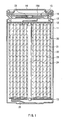
- Fig. 1 shows a cross sectional structure of a secondary battery according to the embodiment of the invention.
- This secondary battery is a so-called cylinder type battery, and comprises a spirally wound electrode body 20 wherein a strip-shaped cathode 21 and a strip-shaped anode 22 are wound with a separator 23 in between inside a battery can 11 in the shape of an approximately hollow cylinder.
- the battery can 11 is made of, for example, iron (Fe) plated by nickel (Ni). One end of the battery can 11 is closed, and the other end of the battery can 11 is opened.
- a pair of insulating plates 12 and 13 are respectively arranged so that the spirally wound electrode body 20 is sandwiched between the insulating plates 12 and 13, and the insulating plates 12 and 13 are located perpendicular to the winding periphery face.
- a battery cover 14 and a safety valve mechanism 15 and a PTC device (Positive Temperature Coefficient device) 16 provided inside the battery cover 14 are mounted through caulking by a gasket 17. Inside of the battery can 11 is closed.
- the battery cover 14 is, for example, made of a material similar to that of the battery can 11.
- the safety valve mechanism 15 is electrically connected to the battery cover 14 through the PTC device 16.
- a disk plate 15A flips to cut the electrical connection between the battery cover 14 and the electrode winding body 20.
- the PTC device 16 limits a current by increasing its resistance value to prevent abnormal heat generation by a large current.
- the gasket 17 is made of, for example, an insulating material and its surface is coated with asphalt.
- the spirally wound electrode body 20 is wound around, for example, a center pin 24.
- a cathode lead 25 made of aluminum or the like is connected to the cathode 21 of the spirally wound electrode body 20.
- An anode lead 26 made of nickel or the like is connected to the anode 22.
- the cathode lead 25 is electrically connected to the battery cover 14 by being welded to the safety valve mechanism 15.
- the anode lead 26 is welded and electrically connected to the battery can 11.
- Fig. 2 is an enlarged view of part of the spirally wound electrode body 20 shown in Fig. 1.
- the cathode 21 comprises, for example, a cathode current collector 21A having a pair of facing faces and cathode active material layer 21B provided on both sides or on a single side of the cathode current collector 21A.
- the cathode current collector 21A is made of, for example, a metal foil such as an aluminum foil, a nickel foil, and a stainless foil.
- the cathode active material layer 21B contains, for example, a cathode material capable of inserting and extracting lithium as a cathode active material.
- a lithium-containing compound which contains lithium, a transition metal element, and oxygen is preferably contained in order to improve an energy density.
- a lithium-containing compound which contains at least one from the group consisting of cobalt (Co), nickel, and manganese (Mn) as a transition metal.
- Examples of such a lithium-containing compound include, for example, LiCoO 2 and LiNiCoO 2 .
- the foregoing cathode material is prepared by mixing a carbonate, a nitrate, an oxide, or a hydroxide of lithium; and a carbonate, a nitrate, an oxide, or a hydroxide of a transition metal so as to obtain a desired composition, pulverizing the mixture, and firing the resultant at a temperature within the range of 600°C to 1,000°C in oxygen atmosphere.
- the cathode active material layer 21B contains, for example, a conductive agent.
- the cathode active material layer 21B can further contain a binder as necessary.
- the conductive agent include carbon materials such as graphite, carbon black, and Ketjen black. One of them or a mixture of two or more of them is used. In addition to the carbon materials, a metal material or a conductive high molecular weight material can be used as long as the material has conductivity.
- the binder include synthetic rubber such as styrene butadiene rubber, fluorinated rubber, and ethylene propylene diene rubber; and high molecular weight materials such as polyvinylidene fluoride. One of them or a mixture of two or more of them is used. For example, as shown in Fig. 1, when the cathode 21 and the anode 22 are wound, as a binder, flexible styrene butadiene rubber, fluorinated rubber or the like is preferably used.
- the anode 22 comprises, for example, an anode current collector 22A having a pair of facing faces and anode active material layer 22B provided on both sides or on a single side of the anode current collector 22A.
- the anode current collector 22A is preferably made of, for example, copper (Cu), stainless, nickel, titanium (Ti), tungsten (W), molybdenum (Mo), or aluminum. Specially, in some cases, the anode current collector 22A is more preferably made of a metal easy to be alloyed with the anode active material layer 22B.
- the anode active material layer 22B contains at least one from the group consisting of simple substances, alloys, and compounds of silicon (Si) and tin (Sn), copper, titanium, aluminum, and nickel can be cited as a material easy to be alloyed with the anode active material layer 22B.
- the anode current collector 22A can be constructed by a single layer, it can be also constructed by several layers. In this case, it is possible that a layer contacting with the anode active material layer 22B is made of the metal material easy to be alloyed with the anode active material layer 22B, and other layers are made of other metal material.
- a surface roughness of the anode current collector 22A is preferably 0.1 ⁇ m or more by arithmetic average roughness Ra. The reason thereof is that a shape of fracture raised by expansion and shrinkage of the anode active material layer 22 in accordance with charge and discharge can be controlled, and a stress is dispersed so that structure destruction of the anode 22 can be inhibited.
- the anode active material layer 22B includes, for example, at least one from the group consisting of simple substances, alloys, and compounds of metal elements capable of forming an alloy with lithium; and simple substances, alloys, and compounds of metalloid elements capable of forming an alloy with lithium as an anode active material. Therefore, a capacity of the anode 22 includes a capacity component derived from inserting and extracting lithium by the anode active material. Consequently, a high energy density can be obtained.
- metal elements or the metalloid elements include tin (Sn), lead (Pb), aluminum, indium (In), silicon (Si), zinc (Zn), antimony (Sb), bismuth (Bi), cadmium (Cd), magnesium (Mg), boron (B), gallium (Ga), germanium (Ge), arsenic (As), silver (Ag), zirconium (Zr), yttrium (Y) and hafnium (Hf).
- compounds thereof include ones which are expressed by a chemical formula of M ⁇ s1 M ⁇ s2 Li s3 , or a chemical formula of M ⁇ s4 M ⁇ s5 M ⁇ s6 .
- M ⁇ represents at least one of metal elements and metalloid elements capable of forming an alloy with lithium, and M ⁇ represents at least one of metal elements and metalloid elements other than lithium and M ⁇ .
- M ⁇ represents at least one of nonmetallic elements, and M ⁇ represents at least one of metal elements and metalloid elements other than M ⁇ .
- Values of s1, s2, s3, s4, s5, and s6 satisfy s1>0, s2 ⁇ 0, s3 ⁇ 0, s4>0, s5>0, and s6 ⁇ 0, respectively.
- Simple substances, alloys, or compounds of metal elements or metalloid elements in Group 4B in the short-period periodic table are preferable.
- Simple substances, alloys, or compounds of silicon and tin are particularly preferable, since their ability to insert and extract lithium is high, and they can improve an energy density of the anode 22 compared to conventional graphite depending on applied combination.
- These materials can be crystalline or amorphous ones.
- Such compounds include LiAl, AlSb, CuMgSb, SiB 4 , SiB 6 , Mg 2 Si, Mg 2 Sn, Ni 2 Si, TiSi 2 , MoSi 2 , CoSi 2 , NiSi 2 , CaSi 2 , CrSi 2 , Cu 5 Si, FeSi 2 , MnSi 2 , NbSi 2 , TaSi 2 , VSi 2 , WSi 2 , ZnSi 2 , SiC, Si 3 N 4 , Si 2 N 2 O, SiO v (0 ⁇ v ⁇ 2), SnO w (0 ⁇ w ⁇ 2), SnSiO 3 , LiSiO, and LiSnO.
- the anode active material layer 22B is preferably formed by at least one method from the group consisting of vapor-phase deposition method, liquid-phase deposition method, and sintering method. These methods are preferable, since destruction due to expansion and shrinkage of the anode active material layer 22B in accordance with charge and discharge can be inhibited, the anode current collector 22A and the anode active material layer 22B can be unified, and an electronic conductivity in the anode active material layer 22B can be improved. Further, these methods are preferable since a binder, voids and so on can be reduced or excluded, and the anode 22 can become a thin film.
- the anode active material layer 22B is alloyed with the anode current collector 22A at least on part of the interface with the anode current collector 22A. More specifically, it is preferable that on the interface, component elements of the anode current collector 22A are diffused into the anode active material layer 22B, or component elements of the anode active material are diffused into the anode current collector 22A, or component elements of both the anode current collector 22A and the anode active material layer 22B are diffused into each other.
- This alloying often arises concurrently with forming the anode active material layer 22B by vapor-phase deposition method, liquid-phase deposition method, or sintering method. However, the alloying can be caused by further heat treatment, or in initial charge.
- the anode active material layer 22B can be formed by coating as well.
- the anode active material layer 22B can contain powders of the anode active material and a binder such as polyvinylidene fluoride as necessary.
- the anode active material layer 22B can contain other anode active material in addition to at least one from the group consisting of simple substances, alloys, and compounds of metal elements or metalloid elements capable of forming an alloy with lithium.
- carbon materials such as graphite, non-graphitizable carbon, and graphitizable carbon are preferable. When using these carbon materials, change in crystal structure raised in charge and discharge is very small. Therefore, when these carbon materials are contained in addition to a simple substance, an alloy, or a compound of metal elements or metalloid elements capable of forming an alloy with lithium, a high energy density can be obtained, and excellent cycle characteristics can be obtained.
- Graphite having a true density of, for example, 2.10 g/cm 3 or over is preferable, and one having a true density of 2.18 g/cm 3 or over is more preferable.
- a thickness of C axis crystal on (002) plane is 14.0 nm or more. Face distance of the (002) plane is preferably less than 0.340 nm, and more preferably within the range of 0.335 nm to 0.337 nm.
- Graphite can be either natural graphite or artificial graphite.
- the artificial graphite can be obtained by, for example, carbonizing an organic material, performing high temperature heat treatment, pulverizing and classifying the resultant.
- the high temperature heat treatment is performed, for example, by carbonizing an organic material at 300°C to 700°C in air currents of inert gas such as nitrogen (N 2 ) as necessary, raising temperature up to 900°C to 1,500°C at a rate of 1°C to 100°C per minute, maintaining such temperature for about 0 to 30 hours, firing, heating up to 2,000°C or higher, preferably 2,500°C or higher, and maintaining the temperature for appropriate time.
- inert gas such as nitrogen (N 2 )
- carbon or pitch can be used as an organic material of a starting material.
- the pitch include a material which is obtained by distillation (vacuum distillation, atmospheric distillation, or steam distillation), thermal polycondensation, extraction, and chemical polycondensation of tars, obtained by thermally decomposing coal tar, ethylene bottom oil, crude oil or the like at high temperatures, asphalt or the like, a material produced during destructive distillation of wood, a polyvinyl chloride resin, polyvinyl acetate, polyvinyl butyrate, or a 3,5-dimethylphenol resin.
- Such coals and pitches exist in a liquid state in the middle of carbonization at up to about 400°C. When maintained at such temperature, aromatic rings condense with each other, turn polycyclic, and their orientation becomes lamination. After that, at about 500°C or higher, a solid carbon precursor, that is semicoke is obtained (liquid phase carbonization process).
- condensation polycyclic hydrocarbon compounds such as naphthalene, phenanthrene, anthracene, triphenylene, pyrene, perylene, pentaphene, pentacene; their derivatives (for example, carboxylic acid, carboxylic anhydride, and carboxylic acid imide of the foregoing compounds), or mixtures thereof can be used.
- condensation heterocyclic compound such as acenaphthylene, indole, isoindole, quinoline, isoquinoline, quinoxaline, phthaladine, carbazole, acridine, phenazine, and phenantolidine, their derivatives, or mixtures thereof can be also used.
- Pulverization can be performed either before and after carbonization or calcination, or during a rise in temperature before graphitization. In these cases, heat treatment for graphitization is performed in powder state finally. However, in order to obtain graphite powders having a high bulk density and a high breaking strength, it is preferable that a raw material is firstly molded, heat treatment is subsequently performed, and then the obtained graphitized molded body is pulverized and classified.
- the graphitized molded body when the graphitized molded body is formed, cokes of a filler and binder pitch of a molding agent or a sintering agent are mixed and molded. After that, a firing process wherein heat treatment is performed for the molded body at low temperatures of 1,000°C or below, and a pitch impregnation process wherein the melted binder pitch is impregnated in the fired body are repeated several times. Then, heat treatment is performed at high temperatures. In the foregoing heat treatment process, the impregnated binder pitch is carbonized and graphitized. In this case, raw materials are the filler (cokes) and the binder pitch. Therefore, graphitization proceeds as a polycrystalline body. Further, sulfur and nitrogen contained in the raw materials are generated as gas in the heat treatment.
- a filler having molding characteristics and sintering characteristics in itself can be used as well. In this case, it is not necessary to use the binder pitch.
- the non-graphitizable carbon whose face distance of the (002) plane is 0.37 nm or more, whose true density is less than 1.70 g/cm 3 , and which does not show an exothermic peak at 700°C or more in differential thermal analysis (DTA) in the air is preferable.
- Such non-graphitizable carbon can be obtained by, for example, providing an organic material with heat treatment at about 1,200°C, pulverizing and classifying the resultant.
- the heat treatment is performed, for example, by carbonizing the organic material at 300°C to 700°C (solid phase carbonization process), raising temperature up to 900°C to 1,300°C at a rate of 1°C to 100°C per minute, and maintaining such temperature for about 0 to 30 hours.
- Pulverization can be performed either before and after carbonization or during a rise in temperature.
- an organic material of a starting material for example, a polymer and a copolymer of furfuryl alcohol or furfural, or a furan resin, which a copolymer of these macromolecules and other resin can be used.
- Conjugated resins such as a phenol resin, an acrylate resin, a vinyl halide resin, a polyimide resin, a polyamideimide resin, a polyamide resin, polyacetylene, polyparaphenylene or the like; cellulose or its derivatives; coffee beans; bamboo; crustacea containing chitosan; biocellulose utilizing bacteria can be also used.
- a compound wherein a functional group containing oxygen is introduced into petroleum pitch whose atomicity ratio H/C between hydrogen atom (H) and carbon atom (C) is, for example, 0.6 to 0.8 (so-called oxygen cross-linking) can be also used.
- Content percentage of oxygen in this compound is preferably 3% or more, and more preferably 5% or more (refer to Japanese Unexamined Patent Application Publication No. H03-252053).
- a content percentage of oxygen affects a crystal structure of a carbon material. Therefore, when a content percentage of oxygen is the foregoing percentage or more, physical properties of the non-graphitizable carbon can be improved, and a capacity of the anode 22 can be improved.
- the petroleum pitch can be obtained by, for example, distillation (vacuum distillation, atmospheric distillation, or steam distillation), thermal polycondensation, extraction, or chemical polycondensation of tars obtained by thermally decomposing coal tar, ethylene bottom oil, crude oil or the like at high temperatures, asphalt or the like.
- oxygen cross-link for example, wet process to react an aqueous solution such as nitric acid, sulfuric acid, hypochlorous acid, and mixed acid thereof with petroleum pitch; dry method to react oxidizing gas such as air and oxygen with petroleum pitch; or a method to react a solid reagent such as sulfur, ammonium nitrate, persulfate ammonia, and ferric chloride with petroleum pitch can be used.
- aqueous solution such as nitric acid, sulfuric acid, hypochlorous acid, and mixed acid thereof with petroleum pitch
- oxidizing gas such as air and oxygen with petroleum pitch
- a solid reagent such as sulfur, ammonium nitrate, persulfate ammonia, and ferric chloride with petroleum pitch
- An organic material of a starting material is not limited to the foregoing.
- Other organic materials can be used as long as they can become non-graphitizable carbon through the solid phase carbonization process by oxygen cross-linking or the like.
- non-graphitizable carbon in addition to non-graphitizable carbon formed of the foregoing organic material as a starting material, a compound whose main components are phosphorous, oxygen, and carbon, described in Japanese Unexamined Patent Application Publication No. H03-137010 is preferable since it shows the above-mentioned physical property parameters.
- the separator 23 is constructed of, for example, a porous film made of a synthetic resin of polytetrafluoro ethylene, polypropylene, polyethylene or the like or a porous film made of ceramics.
- the separator 23 can have a structure in which two or more of the foregoing porous films are layered.
- the porous film made of polyolefin is preferable since it has an excellent short circuit prevention effect, and has ability to improve battery safety by shutdown effect.
- polyethylene is preferable since it has ability to obtain shutdown effect within the range of 100°C to 160°C, and it has excellent electrochemical stability.
- polypropylene is preferable. It is possible to use other resin with chemical stability by copolymerizing with polyethylene or polypropylene, or blending them.
- the electrolytic solution which is a liquid electrolyte, is impregnated in the separator 23.
- the electrolytic solution contains, for example, a liquid solvent such as a nonaqueous solvent, for example, an organic solvent, and an electrolyte salt dissolved in the nonaqueous solvent.
- the electrolytic solution also contains various additives as necessary.
- the liquid nonaqueous solvent is made of, for example, a nonaqueous compound, having an intrinsic viscosity of 10.0 mPa ⁇ s or less at 25°C.
- the liquid nonaqueous solvent having an intrinsic viscosity of 10.0 mPa ⁇ s or less when the electrolyte salt is dissolved can be also used.
- the solvent having an intrinsic viscosity of 10.0 mPa ⁇ s or less in mixed state can be used.
- nonaqueous solvent various conventionally used nonaqueous solvents can be used.
- the nonaqueous solvent include cyclic carbonic acid ester such as propylene carbonate and ethylene carbonate; chain ester such as diethyl carbonate, dimethyl carbonate, and ethyl methyl carbonate; and ethers such as ⁇ -butyrolactone, sulfolane, 2-methyl tetrahydrofuran, and dimethoxy ethane. These materials can be used by themselves, or a mixture of several kinds of them can be used. Specifically, in view of oxidation stability, it is preferable to include carbonic acid ester.
- An electrolyte salt preferably includes one or more light metallic salt having M-X bond where M represents a transition metal element or a 3B Group element, a 4B Group element, or a 5B Group element in the short-period periodic table; and X represents oxygen or sulfur. It is thought that such a light metallic salt can form a stable coating on the surface of the anode 22, inhibit decomposition reaction of the solvent in the anode 22, and prevent reaction between the anode 22 and the solvent.
- the cyclic compound is preferable. It is thought that cyclic parts also relate to coating formation, so that a stable coating can be obtained.
- R11 represents a group expressed by Chemical formula 2 or Chemical formula 3.
- R12 represents halogen, an alkyl group, a halogenated alkyl group, an aryl group, or a halogenated aryl group.
- X11 and X12 represent oxygen and sulfur, respectively.
- M11 represents a transition metal element or a 3B Group element, a 4B Group element, or a 5B Group element in the short-period periodic table.
- M21 represents a 1A Group element, or a 2A Group element in the short-period periodic table or aluminum.
- a is an integer number of 1 to 4
- b is an integer number of 0 to 8
- c, d, e, and f are integer numbers of 1 to 3, respectively.
- R21 represents an alkylene group, a halogenated alkylene group, an arylene group, or a halogenated arylene group.
- R11 represents a group expressed by Chemical formula 2 or Chemical formula 3.
- R12 represents halogen, an alkyl group, a halogenated alkyl group, an aryl group, or a halogenated aryl group.
- X11 and X12 represent oxygen and sulfur, respectively.
- M11 represents a transition metal element or a 3B Group element, a 4B Group element, or a 5B Group element in the short-period periodic table.
- M21 represents a 1A Group element, or a 2A Group element in the short-period periodic table or aluminum.
- b1 is an integer number of 1 to 8
- c, d, e, and f are integer numbers of 1 to 3, respectively.
- R11 represents a group expressed by Chemical formula 2 or Chemical formula 3.
- R13 represents halogen.
- M12 represents phosphorous (P) or boron (B).
- M21 represents a 1A Group element, or a 2A Group element in the short-period periodic table or aluminum.
- b2 is 2 or 4 and c, d, e, and f are integer numbers of 1 to 3, respectively.
- difluoro [oxalato-O, O'] lithium borate expressed by Chemical formula 6, or tetra fluoro [oxalato-O, O'] lithium phosphate expressed by Chemical formula 7 is preferable.
- the compound having B-O bond or P-O bond can provide higher effects, particularly the compound having O-B-O bond or O-P-O bond can provide even higher effects.
- bis [oxalato.O, O'] lithium borate expressed by Chemical formula 8 difluorodi [oxalato-O, O'] lithium phosphate expressed by Chemical formula 9, or tris [oxalato-O, O'] lithium phosphate expressed by Chemical formula 10 is preferable.
- They are compounds which are derived from Chemical formula 1, in the case that an integer number a of Chemical formula 1 is 2 or 3.
- Chemical formulas 6 and 7 they have O-B-O bond or O-P-O bond, so that they can provide higher effects.
- lithium salt having M-X bond in addition to the foregoing, bis [1,2-benzene diorate (2-)-O, O'] lithium borate expressed by Chemical formula 11, and tris [1,2-benzene diorate (2-)-O, O'] lithium phosphate expressed by Chemical formula 12 are also preferable for the same reason as above.
- the electrolyte salt contains one or more other light metallic salt in addition to the light metallic salt having M-X bond.
- Other light metallic salts include a lithium salt expressed by Chemical formula 13 such as LiB (C 6 H 5 ) 4 , LiCH 3 SO 3 , LiCF 3 SO 3 , LiAlCl 4 , LiSiF 6 , LiCl, LiBr, LiPF 6 , LiBF 4 , LiClO 4 , LiAsF 6 , LiN(CF 3 SO 2 ) 2 , LiN(C 2 F 5 SO 2 ) 2 , and LlN(C 4 F 9 SO 2 ) (CF 3 SO 2 ), and a lithium salt expressed by Chemical formula 14 such as LiC(CF 3 SO 2 ) 3 .
- Chemical formula 13 LiN (C m F 2m+1 SO 2 ) (C n F 2n+1 SO 2 )
- LiPF 6 when at least one from the group consisting of LiPF 6 , LiBF 4 , LiClO 4 , LiAsF 6 , a lithium salt expressed by Chemical formula 13, and a lithium salt expressed by Chemical formula 14 is preferably contained, higher effects and a high conductivity can be obtained. Specially, it is particularly preferable to include LiPF 6 .
- the content (density) of the electrolyte salt in relation to the solvent is preferably within the range from 0.3 mol/kg to 3.0 mol/kg. If out of this range, there is the possibility that sufficient battery characteristics cannot be obtained due to extreme decrease of ion conductivity.
- the content of the light metallic salt having M-X bond is preferably within the range from 0.01 mol/kg to 2.0 mol/kg in relation to the solvent. In this range, higher effects can be obtained.
- a gelatinous electrolyte wherein an electrolytic solution is held in a high molecular weight compound can be used.
- the gelatinous electrolyte has an ion conductivity of 1 mS/cm or more at room temperatures, its composition and structure of the high molecular weight compound are not particularly limited.
- the electrolytic solution (that is, a liquid solvent, an electrolyte salt and an additive) is as mentioned above.
- the high molecular weight compound examples include poly acrylic nitrile, polyvinylidene fluoride, a copolymer of polyvinylidene fluoride and poly hexafluoro propylene, poly tetra fluoro ethylene, poly hexafluoro propylene, polyethylene oxide, poly propylene oxide, poly phosphagen, poly siloxane, polyvinyl acetate, polyvinyl alcohol, polymethacrylic acid methyl, polyacrylic acid, polymethacrylic acid, styrene-butadiene rubber, nitrile-butadiene rubber, polystyrene, and poly carbonate.
- a high molecular weight compound having a structure of poly acrylic nitrile, polyvinylidene fluoride, poly hexafluoro propylene, or polyethylene oxide is desirable.
- an additive amount of the high molecular weight compound in relation to the electrolytic solution is preferably from 30 wt% to 50 wt% of the electrolytic solution, though depending on compatibility therebetween.
- the content of the electrolyte salt is similar to the case of the electrolytic solution.
- the solvent does not mean only a liquid solvent.
- the solvent widely covers ones which can disassociate the electrolyte salt, and has ion conductivity. Therefore, when a high molecular weight compound having the ion conductivity is used, this high molecular weight compound is also included in the solvent.
- This secondary battery can be manufactured as follows, for example.
- the cathode 21 is fabricated by forming the cathode active material layer 21B on the cathode current collector 21A.
- the cathode active material layer 21B is formed as follows. First, a cathode active material powders, a conductive agent, and a binder are mixed to prepare a cathode mixture. This cathode mixture is dispersed in a solvent such as N-methyl-2-pyrrolidone to obtain a cathode mixture slurry in paste form. Next, this cathode mixture slurry is applied to the cathode current collector 21A, dried, and compression-molded to form the cathode active material layer 21B.
- a solvent such as N-methyl-2-pyrrolidone
- the anode 22 is fabricated by forming the anode active material layer 22B on the anode current collector 22A.
- the anode active material layer 22B is formed by depositing the anode active material on the anode current collector 22A by using vapor-phase deposition method or liquid-phase deposition method.
- the anode active material layer 22B can be formed by sintering method, wherein a precursor layer containing a particulate anode active material is formed on the anode current collector 22A, and then sintered.
- the anode active material layer 22B can be formed by combining two or three methods from vapor-phase deposition method, liquid-phase deposition method, and sintering method.
- the anode active material layer 22B by using at least one method from the group consisting of vapor-phase deposition method, liquid-phase deposition method, and sintering method, the anode active material layer 22B whose at least part of interface with the anode current collector 22A is alloyed with the anode current collector 22A can be formed.
- the interface between the anode current collector 22A and the anode active material layer 22B it is possible to additionally perform heat treatment under vacuum atmosphere or non-oxidizing atmosphere.
- the anode active material layer 22B when the anode active material layer 22B is formed by plating as described later, the anode active material layer 22B may be hard to be alloyed even on the interface with the anode current collector 22A. Therefore, in this case, this heat treatment is preferably performed as necessary.
- the anode active material layer 22B is formed by vapor-phase deposition method, further alloying the interface between the anode current collector 22A and the anode active material layer 22B may also improve the characteristics. Therefore, in this case, this heat treatment is also preferably performed as necessary.
- vapor-phase deposition method for example, physical deposition method or chemical deposition method can be used. More specifically, vacuum deposition method, sputtering method, ion plating method, laser ablation method, thermal CVD (chemical vapor deposition) method, plasma CVD method or the like can be utilized. As liquid-phase deposition method, known methods such as electrolytic plating and electroless plating can be utilized. Regarding sintering method, known methods can be utilized. For example, atmospheric sintering method, reaction sintering method, and hot press sintering method can be utilized.
- the anode active material layer 22B can be formed by coating as well.
- An example of the concrete method is as follows. First, an anode active material powders and a binder are mixed to prepare an anode mixture. This anode mixture is dispersed in a solvent such as N-methyl-2-pyrrolidone to obtain an anode mixture slurry in paste form. Next, this anode mixture slurry is applied to the anode current collector 22A, dried, and compression-molded to form the anode active material layer 22B.
- the anode active material layer 22B is more preferably formed by at least one method from the group consisting of vapor-phase deposition method, liquid-phase deposition method, and sintering method.
- adhesion between the anode current collector 22A and the anode active material layer 22B can be improved, and alloying between the anode current collector 22A and the anode active material layer 22B often proceeds concurrently with formation of the anode active material layer 22B.
- the cathode lead 25 is attached on the cathode current collector 21A by welding or the like and the anode lead 26 is attached on the anode current collector 22A by welding or the like.
- the cathode 21 and the anode 22 are wound with the separator 23 in between.
- An end of the cathode lead 25 is welded to the safety valve mechanism 15, and an end of the anode lead 26 is welded to the battery can 11.
- the wound cathode 21 and anode 22 are sandwiched between the pair of insulating plates 12 and 13, and the cathode 21 and the anode 22 are housed inside the battery can 11.
- lithium ions when charged, for example, lithium ions are extracted from the cathode 21, and are inserted in the anode 22 through the electrolyte.
- lithium ions When discharged, for example, lithium ions are extracted from the anode 22, and are inserted in the cathode 21 through the electrolyte.
- a stable coating is formed on the surface of the anode 22 by the light metallic salt having M-X bond, and decomposition reaction of the solvent is inhibited.
- reaction between the anode 22 and the solvent can be prevented.
- the electrolyte contains the light metallic salt having M-X bond. Therefore, even when the anode 22 includes at least one from the group consisting of simple substances, alloys, and compounds of metal elements or metalloid elements capable of forming an alloy with lithium, decomposition reaction of the solvent in the anode 22 can be inhibited. Further, reaction between the anode 22 and the solvent can be prevented. Consequently, a high capacity can be obtained, charge and discharge efficiency can be improved, and various characteristics such as cycle characteristics can be improved.
- this cathode mixture was dispersed in N-methyl-2-pyrolidone of a solvent to obtain a cathode mixture slurry.
- This cathode mixture slurry was uniformly applied on both sides of the cathode current collector 21A made of a strip shaped aluminum foil having a thickness of 20 ⁇ m, dried, and compression-molded to form the cathode active material layer 21B. Then, the resultant was cut in the shape of a strip to form the strip shaped cathode 21. After that, the cathode lead 25 made of aluminum was attached on one end of the cathode current collector 21A.
- anode mixture 80 parts by mass of copper-silicon alloy powders, 10 parts by mass of scale-like graphite as an anode active material and 2 parts by mass of acetylene black as a conductive agent, and 8 parts by mass of polyvinylidene fluoride as a binder were mixed to prepare an anode mixture. Subsequently, this anode mixture was dispersed in N-methyl-2-pyrrolidone of a solvent to obtain an anode mixture slurry. The anode mixture slurry was uniformly applied on the both sides of the anode current collector 22A made of a strip shaped electrolytic copper foil having a thickness of 15 ⁇ m, dried, and compression-molded to form the anode active material layer 22B. The resultant was cut in the shape of a strip to form the strip shaped anode 22. After that, the anode lead 26 made of nickel was attached on one end of the anode current collector 22A.
- the separator 23 made of a micro-porous polyethylene having a thickness of 25 ⁇ m was prepared.
- the anode 22, the separator 23, the cathode 21, and the separator 23 were layered in this order, and this lamination was spirally wound several times.
- the spirally wound electrode body 20 was thereby fabricated.
- the spirally wound electrode body 20 was sandwiched between the pair of insulating plate 12 and 13.
- the anode lead 26 was welded to the battery can 11
- the cathode lead 25 was welded to the safety valve mechanism 15, and the winding body 20 was housed inside the battery can 11 made of nickel-plated iron.
- the electrolytic solution was injected into the battery can 11 by decompression method.
- the electrolytic solution wherein the light metallic salt as an electrolyte salt was dissolved in the solvent obtained by mixing 50 vol% of ethylene carbonate and 50 vol% of diethyl carbonate was used.
- Examples 1-1 to 1-18 in Table 1 kinds and contents of the light metallic salt were changed as shown in Examples 1-1 to 1-18 in Table 1.
- Example 1-1 difluoro [oxalato-O, O'] lithium borate expressed by Chemical formula 6 was used.
- Examples 1-2 to 1-16 a mixture of difluoro [oxalato-O, O'] lithium borate and other light metallic salt was used.
- Example 1-17 tetra fluoro [oxalato-O, O'] lithium phosphate expressed by Chemical formula 7 was used.
- Example 1-18 a mixture of tetra fluoro [oxalato-O, O'] lithium phosphate and other light metallic salt was used.
- the battery cover 14 was attached to the battery can 11 through caulking by the gasket 17 whose surface is coated with asphalt.
- the cylindrical secondary batteries having a diameter of 14 mm and a height of 65 mm were thereby obtained for Examples 1-1 to 1-18.
- a secondary battery was fabricated in a manner similar to in Examples 1-1 to 1-18 except that only LiPF 6 was used as an electrolyte salt, and its content was 1.0 mol/kg in relation to the solvent.
- Secondary batteries were fabricated in a manner similar to in Examples 1-1 to 1-18, except that tin was used as the anode active material, the anode active material layer 22B made of tin having a thickness of 2 ⁇ m was formed on the anode current collector 22A made of an electrolytic copper foil having a thickness of 25 ⁇ m by electron beam deposition method, and the resultant was provided with heat treatment for 12 hours at 200°C to form the anode 22.
- kinds and contents of the light metallic salt were changed as shown in Table 2.
- anode active material layer 22B was alloyed with the anode current collector 22A at least on part of the interface with the anode current collector 22A.
- a secondary battery was fabricated in a manner similar to in Examples 2-1 and 2-2, except that only LiPF 6 was used as an electrolyte salt, and its content was 0.1 mol/kg in relation to the solvent.
- Example 2-2 using the light metallic salt having M-X bond, the initial capacity and the capacity retention ratio could be increased, and further the internal resistance could be reduced compared to the Comparative example 2-1 not using the light metallic salt having M-X bond, as in Examples 1-1 and 1-4.
- Example 2-2 using the mixture of the light metallic salt having M-X bond and other light metallic salt, the effect was large.
- Silicon of an anode active material was deposited to form the anode active material layer, and coin type secondary batteries shown in Fig. 3 were fabricated.
- a discoid cathode 31 and a discoid anode 32 are layered with a separator 33 in between, and the lamination is housed between an exterior can 34 and an exterior cup 35.
- lithium cobalt complex oxide of a cathode active material having an average particle diameter of 5 ⁇ m, carbon black of a conductive agent, and polyvinylidene fluoride of a binder were mixed at a mass ratio of 92:3:5 to prepare a cathode mixture.
- this cathode mixture was dispersed in N-methyl-2-pyrolidone of a solvent to obtain a cathode mixture slurry.
- This cathode mixture slurry was applied on a cathode current collector 31A made of a strip shaped aluminum foil having a thickness of 20 ⁇ m, dried, and compression-molded to form a cathode active material layer 31B. The cathode 31 was thereby fabricated.
- An electrolytic copper foil having an arithmetic average roughness Ra of 0.5 ⁇ m and a thickness of 35 ⁇ m was prepared as an anode current collector 32A.
- An anode active material layer 32B made of silicon having a thickness of 4 ⁇ m was formed on this anode current collector 32A by deposition method. The resultant was heated to form the anode 32.
- the obtained anode 32 was analyzed by XPS and AES. In result, it was confirmed that the anode active material layer 32B was alloyed with the anode current collector 32A at least on part of the interface with the anode current collector 32A.
- the anode 32 and the separator 33 made of polypropylene having a thickness of 25 ⁇ m were sequentially layered in the center of the exterior cup 35, the electrolytic solution was injected, the resultant was covered by the exterior can 34 in which the cathode 31 was inserted, and the whole body was provided with caulking through a gasket 36.
- the coin type secondary battery having a diameter of 20 mm and a height of 1.6 mm was thereby fabricated.
- an electrolytic solution solution wherein a light metallic salt as an electrolyte salt was dissolved in a solvent in which ethylene carbonate and diethyl carbonate were mixed at a volume ratio of 1:1 was used.
- Example 3-1 difluoro [oxalato-O, O'] lithium borate expressed by Chemical formula 6 was used.
- Examples 3-2 to 3-21 the mixture of difluoro [oxalato-O, O'] lithium borate and other light metallic salt was used.
- Example 3-22 bis [oxalato-O, O'] lithium borate expressed by Chemical formula 8 was used.
- Examples 3-23 to 3-29 the mixture of bis [oxalato-O, O'] lithium borate and other light metallic salt was used.
- Example 3-30 tetra fluoro [oxalato-O, O'] lithium phosphate expressed by Chemical formula 7 was used.
- Example 3-31 the mixture of tetra fluoro [oxalato-O, O'] lithium phosphate and other light metallic salt was used.
- Example 3-32 difluorodi [oxalato-O, O'] lithium phosphate expressed by Chemical formula 9 was used.
- Example 3-33 the mixture of difluorodi [oxalato-O, O'] lithium phosphate and the other light metallic salt was used.
- Example 3-34 tris [oxalato-O, O'] lithium phosphate expressed by Chemical formula 10 was used.
- Example 3-35 the mixture of tris [oxalato-O, O'] lithium phosphate and other light metallic salt was used.
- Example 3-36 bis [1,2-benzene diorate (2-)-O, O'] lithium borate expressed by Chemical formula 11 was used.
- Example 3-37 the mixture of bis [1,2-benzene diorate (2-)-O, O'] lithium borate and other light metallic salt was used.
- Example 3-38 tris [1,2-benzene diorate (2-)-O, O'] lithium phosphate expressed by Chemical formula 12 was used.
- Example 3-39 the mixture of tris [1,2-benzene diorate (2-)-O, O'] lithium phosphate and other light metallic salt was used.
- the capacity retention ratio could be improved compared to Comparative examples 3-1 to 3-6, not using the light metallic salt having M-X bond, and in some cases the initial capacity could be also improved.
- the initial capacity and the capacity retention ratio could be improved depending on contents. Further, it could be confirmed that when the content of the light metallic salt having M-X bond was from 0.01 mol/kg to 2.0 mol/kg, the capacity and the cycle characteristics could be improved.
- the capacity and the cycle characteristics could be improved if the light metallic salt having M-X bond was included in the electrolytic solution both when silicon of a simple substance of the metalloid elements capable of forming an alloy with lithium was used and when the anode active material layer 32B was formed by vapor-phase deposition method. Further, it was found that when the mixture of the light metallic salt having M-X bond and LiPF 6 was contained in the electrolytic solution, a higher effect could be obtained by adjusting their contents. Furthermore, it was found that the content of the light metallic salt having M-X bond was preferably from 0.01 mol/kg to 2.0 mol/kg.
- Coin type secondary batteries shown in Fig. 3 were fabricated in a manner similar to in Examples 3-1 to 3-39, except that the anode 32 was fabricated by using tin as an anode active material, forming the anode active material layer 32B made of tin having a thickness of 4 ⁇ m on the anode current collector 32A made of an electrolytic copper foil having an arithmetic average roughness Ra of 0.5 ⁇ m and a thickness of 25 ⁇ m by electrolytic plating, and providing the resultant with heat treatment.
- kinds and contents of the light metallic salt were changed as shown in Tables 7 and 8.
- Example 4-1 difluoro [oxalato-O, O'] lithium borate expressed by Chemical formula 6 was used.
- Examples 4-2 to 4-7 the mixture of difluoro [oxalato-O, O'] lithium borate and other light metallic salt was used.
- Example 4-8 tetra fluoro [oxalato-O, O'] lithium phosphate expressed by Chemical formula 7 was used.
- Example 4-9 the mixture of tetra fluoro [oxalato-O, O'] lithium phosphate and other light metallic salt was used.
- Example 4-10 difluorodi [oxalato-O, O'] lithium phosphate expressed by Chemical formula 9 was used.
- Example 4-11 the mixture of difluorodi [oxalato-O, O'] lithium phosphate and the other light metallic salt was used.
- Example 4-12 tris [oxalato-O, O'] lithium phosphate expressed by Chemical formula 10 was used.
- Example 4-13 the mixture of tris [oxalato-O, O'] lithium phosphate and other light metallic salt was used.
- Example 4-14 bis [1,2-benzene diorate (2-)-O, O'] lithium borate expressed by Chemical formula 11 was used.
- Example 4-15 the mixture of bis [1,2-benzene diorate (2-)-O, O'] lithium borate and other light metallic salt was used.
- Example 4-16 tris [1,2-benzene diorate (2-)-O, O'] lithium phosphate expressed by Chemical formula 12 was used.
- Example 4-17 the mixture of tris [1,2-benzene diorate (2-)-O, O'] lithium phosphate and other light metallic salt was used.
- the obtained anode 32 was also analyzed by XPS and AES. In result, it was confirmed that the anode active material layer 32B was alloyed with the anode current collector 32A at least on part of the interface with the anode current collector 32A.
- Coin type secondary batteries shown in Fig. 3 were fabricated in a manner similar to in Examples 3-1 to 3-39, except that tin was used as an anode active material, and the anode active material layer 32B made of tin was formed on the anode current collector 32A made of an electrolytic copper foil having an arithmetic average roughness Ra of 0.5 ⁇ m and a thickness of 25 ⁇ m by sintering method.
- tin powders and polyvinylidene fluoride of a binder were mixed at a mass ratio of 95:5, the mixture was dispersed in N-methyl-2-pyrrolidone of a solvent.
- the resultant was applied to the anode current collector 32A, dried, pressurized, and fired at 200°C to form the anode active material layer 32B.
- the anode 32 was thereby formed.
- Kinds and contents of the light metallic salt were changed as shown in Table 9.
- Example 5-1 bis [oxalato-O, O'] lithium borate expressed by Chemical formula 8 was used.
- Examples 5-2 to 5-8 the mixture of bis [oxalato-O, O'] lithium borate and other light metallic salt was used.
- the obtained anode 32 was also analyzed by XPS and AES. In result, it was confirmed that the anode active material layer 32B was alloyed with the anode current collector 32A at least on part of the interface with the anode current collector 32A.
- a secondary battery was fabricated in a manner similar to in Examples 5-1 to 5-8, except that LiPF 6 was used as an electrolyte salt, and the content was 1.0 mol/kg in relation to the solvent.
- Examples of other electrolytes include a high molecular weight solid electrolyte wherein an electrolyte salt is dispersed in a high molecular weight compound having ion conductivity; an ion conductive inorganic compound consisted of ion conductive ceramics, ion conductive glasses or ionic crystals; a mixture of the ion conductive inorganic compound and an electrolytic solution; and a mixture of the ion conductive inorganic compound and the gelatinous electrolyte/the high molecular weight solid electrolyte.
- the invention can be applied to batteries having other structures, for example, a secondary battery in the shape of an oval or a polygon having a winding structure, or a secondary battery having a structure wherein the cathode and the anode are folded or layered. Further, the invention can be applied to a button type, a square type, or a card type secondary battery. Further, the invention can be applied to primary batteries instead of the secondary batteries.
- anode active material at least one from the group consisting of simple substances, alloys, and compounds of metal elements capable of forming an alloy with the light metal; and simple substances, alloys, and compounds of metalloid elements capable of forming an alloy with the light metal is used.
- the anode capacity includes the capacity component derived from inserting and extracting the light metal by the anode active material.
- a cathode material capable of inserting and extracting the light metal, an electrolyte or the like are selected according to the applied light metal.
Landscapes
- Chemical & Material Sciences (AREA)
- Engineering & Computer Science (AREA)
- Manufacturing & Machinery (AREA)
- Chemical Kinetics & Catalysis (AREA)
- Electrochemistry (AREA)
- General Chemical & Material Sciences (AREA)
- General Physics & Mathematics (AREA)
- Inorganic Chemistry (AREA)
- Condensed Matter Physics & Semiconductors (AREA)
- Physics & Mathematics (AREA)
- Materials Engineering (AREA)
- Secondary Cells (AREA)
- Battery Electrode And Active Subsutance (AREA)
- Cell Electrode Carriers And Collectors (AREA)
Applications Claiming Priority (4)
| Application Number | Priority Date | Filing Date | Title |
|---|---|---|---|
| JP2003166861 | 2003-06-11 | ||
| JP2003166861 | 2003-06-11 | ||
| JP2003414622 | 2003-12-12 | ||
| JP2003414622A JP4186115B2 (ja) | 2003-06-11 | 2003-12-12 | リチウムイオン二次電池 |
Publications (3)
| Publication Number | Publication Date |
|---|---|
| EP1487047A2 true EP1487047A2 (de) | 2004-12-15 |
| EP1487047A3 EP1487047A3 (de) | 2016-03-02 |
| EP1487047B1 EP1487047B1 (de) | 2019-08-07 |
Family
ID=33302290
Family Applications (1)
| Application Number | Title | Priority Date | Filing Date |
|---|---|---|---|
| EP04013471.0A Expired - Lifetime EP1487047B1 (de) | 2003-06-11 | 2004-06-08 | Batterie |
Country Status (5)
| Country | Link |
|---|---|
| US (1) | US7906237B2 (de) |
| EP (1) | EP1487047B1 (de) |
| JP (1) | JP4186115B2 (de) |
| KR (1) | KR100991424B1 (de) |
| CN (1) | CN100440609C (de) |
Cited By (3)
| Publication number | Priority date | Publication date | Assignee | Title |
|---|---|---|---|---|
| WO2010094467A1 (de) * | 2009-02-18 | 2010-08-26 | Chemetall Gmbh | Galvanische zelle mit einer lithiummetall oder eine lithiummetallhaltigen legierung als anodenmaterial und einem elektrolyten mit lithium bis(oxalato)borat sowie mindestens einem weiteren lithiumkomplexsalz |
| WO2010097678A1 (en) * | 2009-02-24 | 2010-09-02 | Toyota Jidosha Kabushiki Kaisha | Lithium-ion secondary battery and manufacture method therefor |
| EP2413416A4 (de) * | 2009-03-25 | 2012-07-11 | Sumitomo Chemical Co | Natriumionenbatterie |
Families Citing this family (64)
| Publication number | Priority date | Publication date | Assignee | Title |
|---|---|---|---|---|
| JP4843936B2 (ja) * | 2004-01-20 | 2011-12-21 | ソニー株式会社 | 二次電池およびその充放電方法 |
| CN100527519C (zh) * | 2004-09-03 | 2009-08-12 | 松下电器产业株式会社 | 非水电解液及含有该非水电解液的二次电池 |
| JP4703203B2 (ja) * | 2005-02-03 | 2011-06-15 | 三洋電機株式会社 | 非水電解質二次電池 |
| JP4876409B2 (ja) * | 2005-03-01 | 2012-02-15 | 日本電気株式会社 | 二次電池用電解液およびそれを用いた二次電池 |
| JP2006278123A (ja) * | 2005-03-29 | 2006-10-12 | Sanyo Electric Co Ltd | 非水電解質二次電池 |
| JP4867218B2 (ja) * | 2005-07-08 | 2012-02-01 | ソニー株式会社 | リチウムイオン二次電池 |
| JP5758560B2 (ja) * | 2005-07-20 | 2015-08-05 | ソニー株式会社 | リチウムイオン二次電池の充電方法 |
| US20070111099A1 (en) * | 2005-11-15 | 2007-05-17 | Nanjundaswamy Kirakodu S | Primary lithium ion electrochemical cells |
| US20080193852A1 (en) * | 2006-02-03 | 2008-08-14 | Sanyo Electric Co., Ltd. | Nonaqueous Electrolyte Secondary Battery |
| JP4994677B2 (ja) | 2006-02-28 | 2012-08-08 | パナソニック株式会社 | 非水電解液二次電池 |
| JP4706528B2 (ja) * | 2006-03-22 | 2011-06-22 | ソニー株式会社 | リチウムイオン二次電池用電解液およびリチウムイオン二次電池 |
| JP2007273182A (ja) * | 2006-03-30 | 2007-10-18 | Sony Corp | 集電体、負極及び電池 |
| JP4605133B2 (ja) * | 2006-06-05 | 2011-01-05 | ソニー株式会社 | 非水電解質およびこれを用いた非水電解質電池、並びに非水電解質の製造方法 |
| JP5498645B2 (ja) * | 2006-10-02 | 2014-05-21 | 三星エスディアイ株式会社 | リチウム二次電池 |
| JP5370630B2 (ja) * | 2006-10-26 | 2013-12-18 | ソニー株式会社 | リチウムイオン二次電池用負極およびリチウムイオン二次電池 |
| CN101202360B (zh) * | 2006-12-14 | 2010-05-19 | 上海比亚迪有限公司 | 一种锂离子二次电池的电解液以及含有该电解液的电池 |
| US9166230B1 (en) | 2007-01-12 | 2015-10-20 | Enovix Corporation | Three-dimensional battery having current-reducing devices corresponding to electrodes |
| WO2008089110A1 (en) | 2007-01-12 | 2008-07-24 | Microazure Corporation | Three-dimensional batteries and methods of manufacturing the same |
| US8367251B2 (en) * | 2007-08-30 | 2013-02-05 | Sony Corporation | Anode with lithium containing ionic polymer coat, method of manufacturing same, secondary battery, and method of manufacturing same |
| KR100918050B1 (ko) | 2007-10-02 | 2009-09-18 | 삼성에스디아이 주식회사 | 리튬 이차 전지용 음극 활물질, 이를 포함하는 리튬 이차전지용 음극, 및 리튬 이차 전지 |
| CN101409347B (zh) * | 2007-10-11 | 2011-01-12 | 比亚迪股份有限公司 | 一种锂离子电池负极片及其制备方法 |
| US10312518B2 (en) | 2007-10-26 | 2019-06-04 | Murata Manufacturing Co., Ltd. | Anode and method of manufacturing the same, and secondary battery |
| JP4793378B2 (ja) * | 2007-11-16 | 2011-10-12 | ソニー株式会社 | 非水電解質電池 |
| US8524394B2 (en) | 2007-11-22 | 2013-09-03 | Samsung Sdi Co., Ltd. | Negative electrode and negative active material for rechargeable lithium battery, and rechargeable lithium battery including same |
| KR100913176B1 (ko) | 2007-11-28 | 2009-08-19 | 삼성에스디아이 주식회사 | 리튬 이차 전지용 음극 및 이를 포함하는 리튬 이차 전지 |
| JP5181740B2 (ja) * | 2008-03-10 | 2013-04-10 | ソニー株式会社 | 二次電池用電解液、二次電池および電子機器 |
| US20090317726A1 (en) * | 2008-04-08 | 2009-12-24 | Sony Corporation | Anode and secondary battery |
| JP5298609B2 (ja) * | 2008-04-08 | 2013-09-25 | ソニー株式会社 | 二次電池用負極および二次電池 |
| US8475957B2 (en) | 2008-04-17 | 2013-07-02 | Enovix Corporation | Negative electrode structure for non-aqueous lithium secondary battery |
| US8133613B2 (en) | 2008-04-17 | 2012-03-13 | Enovix Corporation | Nonaqueous electrolyte secondary battery anode material with a uniform metal-semiconductor alloy layer |
| US8367244B2 (en) | 2008-04-17 | 2013-02-05 | Enovix Corporation | Anode material having a uniform metal-semiconductor alloy layer |
| WO2009128319A1 (ja) * | 2008-04-18 | 2009-10-22 | 株式会社豊田自動織機 | リチウムイオン二次電池用負極とその製造方法 |
| JP5129007B2 (ja) * | 2008-04-18 | 2013-01-23 | 株式会社豊田自動織機 | リチウムイオン二次電池用負極及びその製造方法 |
| CN102246341A (zh) * | 2008-12-12 | 2011-11-16 | 株式会社村田制作所 | 非水电解液二次电池 |
| CN102273000A (zh) * | 2009-01-06 | 2011-12-07 | 株式会社村田制作所 | 非水电解液二次电池 |
| JP5549279B2 (ja) * | 2010-03-05 | 2014-07-16 | 東洋インキScホールディングス株式会社 | 帯電防止剤およびその用途 |
| CN101807717A (zh) * | 2010-04-20 | 2010-08-18 | 诺莱特科技(苏州)有限公司 | 一种凝胶电解液及其制备方法以及使用该凝胶电解液的电池及其制备方法 |
| US9843027B1 (en) | 2010-09-14 | 2017-12-12 | Enovix Corporation | Battery cell having package anode plate in contact with a plurality of dies |
| KR101147239B1 (ko) | 2010-11-02 | 2012-05-18 | 삼성에스디아이 주식회사 | 리튬 이차 전지의 양극 보호막용 조성물, 상기 양극 보호막을 포함하는 리튬 이차 전지 및 그 제조 방법 |
| US9142837B2 (en) * | 2011-09-09 | 2015-09-22 | SCREEN Holdings Co., Ltd. | Lithium ion secondary battery and preparation process of same |
| KR101733736B1 (ko) | 2012-01-06 | 2017-05-10 | 삼성에스디아이 주식회사 | 리튬 이차 전지용 음극 활물질, 그 제조 방법 및 이를 포함하는 리튬 이차 전지 |
| EP2807698B1 (de) | 2012-01-24 | 2018-01-10 | Enovix Corporation | Ionisch durchlässige strukturen für energiespeichereinrichtungen |
| KR20240055130A (ko) | 2012-08-16 | 2024-04-26 | 에노빅스 코오퍼레이션 | 3차원 배터리들을 위한 전극 구조들 |
| CN103151561B (zh) * | 2013-03-05 | 2015-07-01 | 华南师范大学 | 一种电解质锂盐及含有该锂盐的电解液制备方法与应用 |
| CN105308772B (zh) | 2013-03-15 | 2018-11-16 | 艾诺维克斯公司 | 用于三维电池的隔膜 |
| KR101825920B1 (ko) | 2013-07-16 | 2018-03-22 | 삼성에스디아이 주식회사 | 음극 활물질, 이를 채용한 음극과 리튬 전지, 및 상기 음극 활물질의 제조방법 |
| WO2015025650A1 (ja) * | 2013-08-22 | 2015-02-26 | Necエナジーデバイス株式会社 | 負極およびその製造方法、電池 |
| CN105765779B (zh) * | 2013-09-30 | 2019-05-28 | 株式会社Lg化学 | 含基于邻苯二甲酸酯膦的阴离子的电解质、含其的用于二次电池的添加剂和含其的二次电池 |
| CN103746110A (zh) * | 2014-01-26 | 2014-04-23 | 中国科学院长春应用化学研究所 | 一种镍钴锰三元材料的制备方法和锂离子电池正极材料 |
| KR102152883B1 (ko) | 2014-01-27 | 2020-09-07 | 삼성에스디아이 주식회사 | 음극 활물질, 이를 채용한 음극과 리튬 전지, 및 상기 음극 활물질의 제조방법 |
| TWI793480B (zh) | 2015-05-14 | 2023-02-21 | 美商易諾維公司 | 用於能量儲存裝置之縱向約束 |
| US10644307B2 (en) | 2015-08-06 | 2020-05-05 | Kuraray Co., Ltd. | Slurry composition for non aqueous electrolyte battery electrode, and non aqueous electrolyte battery positive electrode and non aqueous electrolyte battery using same |
| US10720646B2 (en) | 2015-08-10 | 2020-07-21 | Kuraray Co., Ltd. | Non aqueous electrolyte battery binder composition, and non aqueous electrolyte battery slurry composition, non aqueous electrolyte battery negative electrode, and non aqueous electrolyte battery using same |
| TWI739830B (zh) | 2016-05-13 | 2021-09-21 | 美商易諾維公司 | 用於三維電池之尺寸拘束件 |
| TWI819481B (zh) | 2016-11-16 | 2023-10-21 | 美商易諾維公司 | 具有可壓縮陰極之三維電池 |
| JP6952777B2 (ja) * | 2017-06-27 | 2021-10-20 | 株式会社日本触媒 | 電解質組成物、電解質膜、電極、電池及び電解質組成物の評価方法 |
| US10256507B1 (en) | 2017-11-15 | 2019-04-09 | Enovix Corporation | Constrained electrode assembly |
| KR102859540B1 (ko) | 2017-11-15 | 2025-09-17 | 에노빅스 코오퍼레이션 | 전극 어셈블리 및 2차 배터리 |
| US11211639B2 (en) | 2018-08-06 | 2021-12-28 | Enovix Corporation | Electrode assembly manufacture and device |
| CN110061292B (zh) * | 2019-03-28 | 2021-04-09 | 合肥国轩高科动力能源有限公司 | 一种低温电解液及使用该电解液的锂电池 |
| JP7844451B2 (ja) | 2020-09-18 | 2026-04-13 | エノビクス・コーポレイション | 電池に使用する電極の製造 |
| CN116783744A (zh) | 2020-12-09 | 2023-09-19 | 艾诺维克斯公司 | 用于制造二次电池的电极组合件的方法及装置 |
| CN112713308A (zh) * | 2020-12-28 | 2021-04-27 | 远景动力技术(江苏)有限公司 | 一种非水电解液及基于其的锂离子电池 |
| WO2023059081A1 (ko) * | 2021-10-06 | 2023-04-13 | 솔브레인 주식회사 | 전해액 및 이를 포함하는 이차전지 |
Family Cites Families (19)
| Publication number | Priority date | Publication date | Assignee | Title |
|---|---|---|---|---|
| JP3060474B2 (ja) | 1989-07-29 | 2000-07-10 | ソニー株式会社 | 電池用負極およびその製造方法ならびにこれを用いた非水電解液電池 |
| JP3136594B2 (ja) | 1990-02-28 | 2001-02-19 | ソニー株式会社 | 非水電解液二次電池 |
| JP2997741B2 (ja) | 1992-07-29 | 2000-01-11 | セイコーインスツルメンツ株式会社 | 非水電解質二次電池及びその製造方法 |
| JP3010226B2 (ja) | 1993-03-10 | 2000-02-21 | セイコーインスツルメンツ株式会社 | 非水電解質二次電池及びその製造方法 |
| JP2948205B1 (ja) * | 1998-05-25 | 1999-09-13 | 花王株式会社 | 二次電池用負極の製造方法 |
| DE19933898A1 (de) * | 1999-07-22 | 2001-02-01 | Chemetall Gmbh | Tris(oxalato)phosphate, Verfahren zu deren Herstellung und deren Verwendung |
| JP2001325989A (ja) | 2000-03-07 | 2001-11-22 | Central Glass Co Ltd | 電気化学ディバイス用電解質、その電解液並びに電池 |
| JP3826746B2 (ja) * | 2000-08-18 | 2006-09-27 | ソニー株式会社 | 非水電解液二次電池 |
| JP4076738B2 (ja) | 2001-06-13 | 2008-04-16 | セントラル硝子株式会社 | リチウム電池及びリチウムイオン電池用電解質、その電解液または固体電解質並びに、リチウム電池またはリチウムイオン電池 |
| EP1195834B1 (de) * | 2000-10-03 | 2010-09-15 | Central Glass Company, Limited | Elektrolyt für elektrochemische Vorrichtung |
| JP3722685B2 (ja) | 2000-10-03 | 2005-11-30 | セントラル硝子株式会社 | 電気化学ディバイス用電解質及びそれを用いた電池 |
| JP2002237294A (ja) | 2001-02-08 | 2002-08-23 | Tokuyama Corp | リチウム二次電池用負極 |
| JP2002270156A (ja) | 2001-03-08 | 2002-09-20 | Sanyo Electric Co Ltd | リチウム二次電池用電極及びリチウム二次電池 |
| JP2002270232A (ja) * | 2001-03-14 | 2002-09-20 | Sony Corp | 電 池 |
| JP2003017069A (ja) | 2001-06-28 | 2003-01-17 | Sanyo Electric Co Ltd | リチウム二次電池用電極及びリチウム二次電池 |
| DE10139409A1 (de) * | 2001-08-17 | 2003-02-27 | Merck Patent Gmbh | Polymerelektrolyte und deren Verwendung in galvanischen Zellen |
| JP4175792B2 (ja) | 2001-08-27 | 2008-11-05 | セントラル硝子株式会社 | 電気化学ディバイス用電解液またはゲル電解質並びに電池 |
| JP4225727B2 (ja) * | 2001-12-28 | 2009-02-18 | 三洋電機株式会社 | リチウム二次電池用負極及びリチウム二次電池 |
| JP3935067B2 (ja) * | 2002-12-26 | 2007-06-20 | ソニー株式会社 | 二次電池用負極およびそれを用いた二次電池 |
-
2003
- 2003-12-12 JP JP2003414622A patent/JP4186115B2/ja not_active Expired - Fee Related
-
2004
- 2004-06-08 EP EP04013471.0A patent/EP1487047B1/de not_active Expired - Lifetime
- 2004-06-08 KR KR1020040041715A patent/KR100991424B1/ko not_active Expired - Fee Related
- 2004-06-10 US US10/866,214 patent/US7906237B2/en active Active
- 2004-06-11 CN CNB2004100119619A patent/CN100440609C/zh not_active Expired - Lifetime
Cited By (4)
| Publication number | Priority date | Publication date | Assignee | Title |
|---|---|---|---|---|
| WO2010094467A1 (de) * | 2009-02-18 | 2010-08-26 | Chemetall Gmbh | Galvanische zelle mit einer lithiummetall oder eine lithiummetallhaltigen legierung als anodenmaterial und einem elektrolyten mit lithium bis(oxalato)borat sowie mindestens einem weiteren lithiumkomplexsalz |
| US9509014B2 (en) | 2009-02-18 | 2016-11-29 | Chemetall Gmbh | Galvanic cell having a lithium metal or an alloy comprising a lithium metal as anode material and an electrolyte having lithium . . . complex salt |
| WO2010097678A1 (en) * | 2009-02-24 | 2010-09-02 | Toyota Jidosha Kabushiki Kaisha | Lithium-ion secondary battery and manufacture method therefor |
| EP2413416A4 (de) * | 2009-03-25 | 2012-07-11 | Sumitomo Chemical Co | Natriumionenbatterie |
Also Published As
| Publication number | Publication date |
|---|---|
| JP2005026203A (ja) | 2005-01-27 |
| EP1487047B1 (de) | 2019-08-07 |
| KR20040106228A (ko) | 2004-12-17 |
| CN100440609C (zh) | 2008-12-03 |
| KR100991424B1 (ko) | 2010-11-03 |
| US20050095503A1 (en) | 2005-05-05 |
| JP4186115B2 (ja) | 2008-11-26 |
| CN1610171A (zh) | 2005-04-27 |
| US7906237B2 (en) | 2011-03-15 |
| EP1487047A3 (de) | 2016-03-02 |
Similar Documents
| Publication | Publication Date | Title |
|---|---|---|
| US7906237B2 (en) | Battery | |
| US7229713B2 (en) | Electrode and battery using the same | |
| KR100809853B1 (ko) | 비수성 전해질 이차 배터리 | |
| US8586246B2 (en) | Positive electrode active material, positive electrode using the same and non-aqueous electrolyte secondary battery | |
| JP4941423B2 (ja) | リチウムイオン二次電池 | |
| EP1487048A2 (de) | Batterie | |
| JP3791797B2 (ja) | 電池 | |
| JP3965567B2 (ja) | 電池 | |
| KR20040023780A (ko) | 비수성 전극 전지 | |
| US20100081064A1 (en) | Non-aqueous electrolyte battery | |
| JP2003157900A (ja) | 電 池 | |
| JP4150202B2 (ja) | 電池 | |
| JP2005197175A (ja) | 正極、負極、電解質および電池 | |
| US20040096742A1 (en) | Positive electrode material and battery comprising it | |
| US20050008940A1 (en) | Battery | |
| JP2005005118A (ja) | 電池 | |
| JP2004200115A (ja) | 負極およびそれを用いた電池 | |
| JP2002270229A (ja) | 電 池 | |
| JP3501365B2 (ja) | 非水電解液二次電池 | |
| JP2004079342A (ja) | 電池 | |
| JP2003187864A (ja) | 電 池 | |
| JP2005222829A (ja) | 電解質および電池 | |
| JP2003157895A (ja) | 電 池 |
Legal Events
| Date | Code | Title | Description |
|---|---|---|---|
| PUAI | Public reference made under article 153(3) epc to a published international application that has entered the european phase |
Free format text: ORIGINAL CODE: 0009012 |
|
| AK | Designated contracting states |
Kind code of ref document: A2 Designated state(s): AT BE BG CH CY CZ DE DK EE ES FI FR GB GR HU IE IT LI LU MC NL PL PT RO SE SI SK TR |
|
| AX | Request for extension of the european patent |
Extension state: AL HR LT LV MK |
|
| RAP1 | Party data changed (applicant data changed or rights of an application transferred) |
Owner name: CENTRAL GLASS CO., LTD. Owner name: SONY CORPORATION |
|
| PUAL | Search report despatched |
Free format text: ORIGINAL CODE: 0009013 |
|
| AK | Designated contracting states |
Kind code of ref document: A3 Designated state(s): AT BE BG CH CY CZ DE DK EE ES FI FR GB GR HU IE IT LI LU MC NL PL PT RO SE SI SK TR |
|
| AX | Request for extension of the european patent |
Extension state: AL HR LT LV MK |
|
| 17P | Request for examination filed |
Effective date: 20160831 |
|
| RBV | Designated contracting states (corrected) |
Designated state(s): AT BE BG CH CY CZ DE DK EE ES FI FR GB GR HU IE IT LI LU MC NL PL PT RO SE SI SK TR |
|
| 17Q | First examination report despatched |
Effective date: 20161011 |
|
| AKX | Designation fees paid |
Designated state(s): DE FR GB |
|
| AXX | Extension fees paid |
Extension state: LV Extension state: HR Extension state: AL Extension state: LT Extension state: MK |
|
| STAA | Information on the status of an ep patent application or granted ep patent |
Free format text: STATUS: EXAMINATION IS IN PROGRESS |
|
| REG | Reference to a national code |
Ref country code: DE Ref legal event code: R079 Ref document number: 602004054170 Country of ref document: DE Free format text: PREVIOUS MAIN CLASS: H01M0010400000 Ipc: H01M0010052000 |
|
| GRAP | Despatch of communication of intention to grant a patent |
Free format text: ORIGINAL CODE: EPIDOSNIGR1 |
|
| STAA | Information on the status of an ep patent application or granted ep patent |
Free format text: STATUS: GRANT OF PATENT IS INTENDED |
|
| RIC1 | Information provided on ipc code assigned before grant |
Ipc: H01M 4/134 20100101ALN20181212BHEP Ipc: H01M 10/0568 20100101ALI20181212BHEP Ipc: H01M 10/052 20100101AFI20181212BHEP Ipc: H01M 10/054 20100101ALI20181212BHEP Ipc: H01M 10/0565 20100101ALN20181212BHEP |
|
| INTG | Intention to grant announced |
Effective date: 20190108 |
|
| RIC1 | Information provided on ipc code assigned before grant |
Ipc: H01M 10/0565 20100101ALN20181218BHEP Ipc: H01M 10/054 20100101ALI20181218BHEP Ipc: H01M 10/0568 20100101ALI20181218BHEP Ipc: H01M 4/134 20100101ALN20181218BHEP Ipc: H01M 10/052 20100101AFI20181218BHEP |
|
| GRAS | Grant fee paid |
Free format text: ORIGINAL CODE: EPIDOSNIGR3 |
|
| GRAA | (expected) grant |
Free format text: ORIGINAL CODE: 0009210 |
|
| STAA | Information on the status of an ep patent application or granted ep patent |
Free format text: STATUS: THE PATENT HAS BEEN GRANTED |
|
| AK | Designated contracting states |
Kind code of ref document: B1 Designated state(s): DE FR GB |
|
| REG | Reference to a national code |
Ref country code: GB Ref legal event code: FG4D |
|
| REG | Reference to a national code |
Ref country code: DE Ref legal event code: R096 Ref document number: 602004054170 Country of ref document: DE |
|
| REG | Reference to a national code |
Ref country code: DE Ref legal event code: R097 Ref document number: 602004054170 Country of ref document: DE |
|
| PLBE | No opposition filed within time limit |
Free format text: ORIGINAL CODE: 0009261 |
|
| STAA | Information on the status of an ep patent application or granted ep patent |
Free format text: STATUS: NO OPPOSITION FILED WITHIN TIME LIMIT |
|
| 26N | No opposition filed |
Effective date: 20200603 |
|
| REG | Reference to a national code |
Ref country code: DE Ref legal event code: R119 Ref document number: 602004054170 Country of ref document: DE |
|
| GBPC | Gb: european patent ceased through non-payment of renewal fee |
Effective date: 20200608 |
|
| PG25 | Lapsed in a contracting state [announced via postgrant information from national office to epo] |
Ref country code: FR Free format text: LAPSE BECAUSE OF NON-PAYMENT OF DUE FEES Effective date: 20200630 Ref country code: GB Free format text: LAPSE BECAUSE OF NON-PAYMENT OF DUE FEES Effective date: 20200608 |
|
| PG25 | Lapsed in a contracting state [announced via postgrant information from national office to epo] |
Ref country code: DE Free format text: LAPSE BECAUSE OF NON-PAYMENT OF DUE FEES Effective date: 20210101 |