EP1426910A2 - Appareil d'affichage de carte, appareil de navigation et méthode d'affichage de carte - Google Patents
Appareil d'affichage de carte, appareil de navigation et méthode d'affichage de carte Download PDFInfo
- Publication number
- EP1426910A2 EP1426910A2 EP03018769A EP03018769A EP1426910A2 EP 1426910 A2 EP1426910 A2 EP 1426910A2 EP 03018769 A EP03018769 A EP 03018769A EP 03018769 A EP03018769 A EP 03018769A EP 1426910 A2 EP1426910 A2 EP 1426910A2
- Authority
- EP
- European Patent Office
- Prior art keywords
- map
- display
- constituent
- dimensional
- displayed
- Prior art date
- Legal status (The legal status is an assumption and is not a legal conclusion. Google has not performed a legal analysis and makes no representation as to the accuracy of the status listed.)
- Withdrawn
Links
Images


Classifications
-
- G—PHYSICS
- G01—MEASURING; TESTING
- G01C—MEASURING DISTANCES, LEVELS OR BEARINGS; SURVEYING; NAVIGATION; GYROSCOPIC INSTRUMENTS; PHOTOGRAMMETRY OR VIDEOGRAMMETRY
- G01C21/00—Navigation; Navigational instruments not provided for in groups G01C1/00 - G01C19/00
- G01C21/26—Navigation; Navigational instruments not provided for in groups G01C1/00 - G01C19/00 specially adapted for navigation in a road network
- G01C21/34—Route searching; Route guidance
- G01C21/36—Input/output arrangements for on-board computers
- G01C21/3626—Details of the output of route guidance instructions
- G01C21/3635—Guidance using 3D or perspective road maps
- G01C21/3638—Guidance using 3D or perspective road maps including 3D objects and buildings
-
- G—PHYSICS
- G01—MEASURING; TESTING
- G01C—MEASURING DISTANCES, LEVELS OR BEARINGS; SURVEYING; NAVIGATION; GYROSCOPIC INSTRUMENTS; PHOTOGRAMMETRY OR VIDEOGRAMMETRY
- G01C21/00—Navigation; Navigational instruments not provided for in groups G01C1/00 - G01C19/00
- G01C21/38—Electronic maps specially adapted for navigation; Updating thereof
- G01C21/3804—Creation or updating of map data
- G01C21/3833—Creation or updating of map data characterised by the source of data
- G01C21/3848—Data obtained from both position sensors and additional sensors
-
- G—PHYSICS
- G01—MEASURING; TESTING
- G01C—MEASURING DISTANCES, LEVELS OR BEARINGS; SURVEYING; NAVIGATION; GYROSCOPIC INSTRUMENTS; PHOTOGRAMMETRY OR VIDEOGRAMMETRY
- G01C21/00—Navigation; Navigational instruments not provided for in groups G01C1/00 - G01C19/00
- G01C21/38—Electronic maps specially adapted for navigation; Updating thereof
- G01C21/3804—Creation or updating of map data
- G01C21/3833—Creation or updating of map data characterised by the source of data
- G01C21/3852—Data derived from aerial or satellite images
-
- G—PHYSICS
- G01—MEASURING; TESTING
- G01C—MEASURING DISTANCES, LEVELS OR BEARINGS; SURVEYING; NAVIGATION; GYROSCOPIC INSTRUMENTS; PHOTOGRAMMETRY OR VIDEOGRAMMETRY
- G01C21/00—Navigation; Navigational instruments not provided for in groups G01C1/00 - G01C19/00
- G01C21/38—Electronic maps specially adapted for navigation; Updating thereof
- G01C21/3863—Structures of map data
- G01C21/3867—Geometry of map features, e.g. shape points, polygons or for simplified maps
-
- G—PHYSICS
- G08—SIGNALLING
- G08G—TRAFFIC CONTROL SYSTEMS
- G08G1/00—Traffic control systems for road vehicles
- G08G1/09—Arrangements for giving variable traffic instructions
- G08G1/0962—Arrangements for giving variable traffic instructions having an indicator mounted inside the vehicle, e.g. giving voice messages
- G08G1/0968—Systems involving transmission of navigation instructions to the vehicle
- G08G1/0969—Systems involving transmission of navigation instructions to the vehicle having a display in the form of a map
-
- G—PHYSICS
- G08—SIGNALLING
- G08G—TRAFFIC CONTROL SYSTEMS
- G08G1/00—Traffic control systems for road vehicles
- G08G1/09—Arrangements for giving variable traffic instructions
- G08G1/0962—Arrangements for giving variable traffic instructions having an indicator mounted inside the vehicle, e.g. giving voice messages
- G08G1/0967—Systems involving transmission of highway information, e.g. weather, speed limits
Definitions
- the present invention relates to a map display device for displaying a three-dimensional map on a screen of a display device.
- a navigation device has been hitherto known as means of improving the convenience of running of a car.
- two-dimensional map vector data which are stored in a storage medium such as a CD-ROM or the like are read out to form a two-dimensional map in which map constituents such as buildings, roads, geographical features, etc. are shown, and the two-dimensional map thus formed is displayed on a display screen of a monitor or the like. Further, a current position (the position of a car), a destination, a route connecting the current position and the destination, etc. are displayed on the display screen while superposed on the two-dimensional map.
- the navigation device is improved so that a user can readily grasp surrounding conditions around the current position by changing the display scale of the two-dimensional map on the display screen or displaying the two-dimensional map in a bird's-eye view mode on the display screen.
- the improvement of the processing on the screen display in the conventional navigation device as described above is performed on the basis of the two-dimensional map. Accordingly, when the current position or the destination is located on a multilevel crossing or a sloping road, or on a road along which many buildings stand, it is difficult to grasp the surrounding conditions of the current position or the destination because the surrounding conditions of these multilevel crossing, the sloping road, etc. are displayed two-dimensionally. Therefore, in order to make it easier to grasp the conditions of the circumferences of the current position and the destination, it is desirable to implement a navigation device for performing a three-dimensional map display in which a projection map to be obtained by viewing a three-dimensional map from any view point is displayed on the display screen.
- the navigation device for displaying the three-dimensional map is implemented, there might occur a case where a map constituent to be noted is hidden by another map constituent and thus it is not displayed on the display screen. In this case, there might also occur a problem that information such as a current position, a destination, a route connecting the current position and the destination or the like which a user wishes to know is not displayed on the screen.
- the present invention has been implemented on the basis of the foregoing situation, and a first object of the present invention is to provide a map display device for performing a three-dimensional map display, which can display on a display screen even information which is located at a position where the information would be hidden.
- a second object of the present invention is to provide a map display device for performing a three-dimensional map display, which can prevent degradation in visibility of attendant information connected to map constituents.
- the map display unit may include view-point position changing means for changing the position of the desired view point to another position at which the desired map constituent can be displayed on the three-dimensional bird's-eye view map, when the desired map constituent specified by the map constituent specifying unit is hidden by the other map constituent which is located nearer to the desired view point than the desired map constituent and thus the desired map constituent is not displayed on the three-dimensional bird's-eye view map.
- the map display unit may include two-dimensional map display means for forming a two-dimensional map on the basis of two-dimensional data of each map constituent and displaying the two-dimensional map on the display screen in place of the three-dimensional bird's-eye view map when the desired map constituent specified by the map constituent specifying unit is hidden by the other map constituent which is located nearer to the desired view point than the desired map constituent and thus the desired map constituent is not displayed on the three-dimensional bird's-eye view map.
- the map display unit may include two-dimensional map bird's-eye view display means for forming, on the basis of two-dimensional data of each map constituent, a two-dimensional bird's-eye view map which is obtained when a two-dimensional map is viewed from a desired view point, and displaying the two-dimensional bird's-eye view map on the display screen in place of the three-dimensional bird's-eye view map when the desired map constituent specified by the map constituent specifying unit is hidden by the other map constituent which is located nearer to the desired view point than the desired map constituent and thus the desired map constituent is not displayed on the three-dimensional bird's-eye view map.
- the map display unit may include duplicative display means for forming a two-dimensional map on the basis of two-dimensional data of each map constituent and displaying the two-dimensional map on the display screen together with the three-dimensional bird's-eye view map when the desired map constituent specified by the map constituent specifying unit is hidden by the other map constituent which is located nearer to the desired view point than the desired map constituent and thus the desired map constituent is not displayed on the three-dimensional bird's-eye view map.
- the map display unit may include duplicative display means for forming, on the basis of two-dimensional data of each map constituent, a two-dimensional bird's-eye view map which is obtained when a two-dimensional map is viewed from a desired view point, and displaying the two-dimensional bird's-eye view map on the display screen together with the three-dimensional bird's-eye view map when the desired map constituent specified by the map constituent specifying unit is hidden by the other map constituent which is located nearer to the desired view point than the desired map constituent and thus the desired map constituent is not displayed on the three-dimensional bird's-eye view map.
- the three-dimensional data of each map constituent is first subjected to a perspective transformation to obtain two-dimensional coordinate data when these map constituents are projected onto a two-dimensional plane (projection plane) from a desired view point.
- a hidden-surface removal processing is performed to remove data of a portion corresponding to a hidden surface of each map constituent which has been subjected to the perspective transformation.
- the hidden surface is defined as the surface of a portion located at the rear side of a map constituent or the surface of a portion which is hidden by a map constituent located at the front side and is thus unseen by a viewer when a three-dimensional map is viewed from a view point.
- the hidden-surface removal processing may be realized by various methods used in the computer graphics field such as a Z sort method, a Z buffer method, a scan line method, a ray casting method or the like.
- various methods may be used to judge whether a desired map constituent specified by the map constituent specifying unit is hidden by another map constituent which is located nearer to a desired view point than the desired map constituent.
- the following method may be used.
- a map constituent having perspectively-transformed two-dimensional coordinate data on a projection plane which is overlapped with the desired map constituent is detected, and the coordinate data in the depth (line of sight) direction of the detected map constituent is compared with that of the desired map constituent to check which map constituent is closer (i.e., is nearer to the view point).
- map constituents or marks which are hidden by map constituents located at the closer side can be displayed. Therefore, even when information which is required to be displayed by the user is located at such a position where it is hidden by a map constituent, a three-dimensional map can be displayed on the display screen.
- a map display device for displaying a map and attendant information associated with map constituents constituting the map on a screen of the display device, comprises: map information storing means for storing three-dimensional information of the map constituents; attendant information storing means for storing the attendant information of the map constituents stored in the map information storing means; three-dimensional map forming means for forming, on the basis of the information stored in the map information storing means, a three-dimensional map in which the map constituents are arranged on the three-dimensional coordinate, view-point setting means for setting a view-point position from which the three-dimensional map formed by the three-dimensional map forming means is viewed to form a projection map; projection map forming means for forming the projection map which is to be obtained by viewing the three-dimensional map formed by the three-dimensional map forming means from the view-point position which is set by the view-point setting means; means for reading out from the attendant information storing means the attendant information corresponding to
- a three-dimensional map in which map constituents are arranged is first formed on the basis of data in the map storage means. Subsequently, the three-dimensional map is subjected to predetermined processing such as affine transformation, perspective transformation or the like, and then subjected to a hidden-surface removal processing such as the Z buffer method or the like to form a projection map which is obtained by viewing the three-dimensional map from a view-point.
- predetermined processing such as affine transformation, perspective transformation or the like
- a hidden-surface removal processing such as the Z buffer method or the like
- the attendant information of a map constituent displayed on the projection map is read out from the attendant information storage means, and then a display area on the projection map of the map constituent which is displayed on the projection map is detected.
- the display area of the attendant information on the projection map is set according to any one of the following rules.
- the attendant information is displayed by being superposed on the corresponding map constituent.
- the layout of the attendant information is set on the basis of the size of the display area of the attendant information.
- the attributes of the character array such as character size, character interval, number of lines, etc. are set so that the character array is located within the display area of the attendant information.
- the attendant information is displayed in the neighborhood of the corresponding map constituent.
- a leading line is added to the attendant information or the attendant information is displayed with the same color or pattern as the corresponding map constituent to maintain the relative positions between the map constituent and the attendant information.
- the attendant information since the size of the display area of the attendant information can be freely set, the attendant information can be displayed in sufficient size.
- the display area of the attendant information on the projection map is set in the manner as described above, and then the attendant information is added onto the display area of the attendant information concerned. Thereafter, the projection map added with the attendant information is displayed on the screen of the display device.
- the display area of the corresponding attendant information on the projection map is set to add the attendant information to the projection map, and then the projection map added with the attendant information is displayed on the screen of the display device.
- the attendant information can be displayed at any conspicuous position at all times in accordance with variation of the map constituent, so that the visibility can be prevented from being lowered. Accordingly, there can be provided high-quality map information in the three-dimensional map display.
- Fig. 1 shows an example of a display frame of the navigation device in which the processing according to the first embodiment of the present invention is performed.
- the points of map constituents such as a building, a road, a geographical feature, etc. on the land are projected onto a plane which is divided in a mesh form according to universal lateral Mercator projection, and three-dimensional data comprising vector data in latitude (X) and longitude (Y) directions of each object on the meshed-plane (corresponding to each map constituent) and vector data in the height (Z) direction of each map constituent are stored in a map data base.
- a projection map (so-called three-dimensional bird's-eye view map) which is obtained by bird's-eye-viewing from a desired view point a three-dimensional map 101 in which respective constituents are arranged on the three-dimensional coordinate is formed on the basis of the map data base, and the three-dimensional bird's-eye view map is displayed on a display 2.
- a vehicle position detected by a sensor such as a GPS (Global Positioning System) or the like, a destination and a route connecting the current position and the destination are displayed by being overlapped with one another.
- the destination and a part of the route which are not drawn in the three-dimensional bird's-eye view map because it is located at the hidden surface side (which cannot be viewed from the view point) of a mount corresponding to a map constituent, can be displayed on the display 2 by executing the processing of this embodiment. Accordingly, information which a user wishes to know is displayed on the display 2.
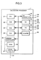
- Fig. 2 shows each constituent unit of the car-mounted type navigation device according to this embodiment.
- a calculation processor 1 is a central unit for performing various processing. For example, it detects the current position on the basis of information output from various sensors 6 to 9, and reads out three-dimensional data of map constituents required for display from a map storage device 3 on the basis of the current position information thus obtained. Further, it develops the three-dimensional data of the map constituents thus read out into graphics, overlaps the developed graphics with a current position mark and displays the result on a display 2, or selects an optimum road connecting the current position and a destination indicated by a user and guides the user to the destination by using a voice input/output device 4 or the display 2.
- the display 2 is a unit for displaying the graphics information generated by the calculation processor 1, and it comprises a CRT or liquid crystal display. Further, it is common practice for that RGB signals or NTSC (National Television System Committee) signals to be used as a signal S1 between the calculation processor 1 and the display 2.
- RGB signals or NTSC National Television System Committee
- the map storage device 3 comprises a large-capacity storage medium such as a CD-ROM or an IC card.
- the large-capacity storage medium there are stored three-dimensional data comprising vector data in latitude (X) and longitude (Y) directions of each object on the meshed-plane (corresponding to each map constituent) and vector data in the height (Z) direction of each map constituent, each object being obtained by projecting the area of each map constituent on the land onto a plane which is divided in a mesh form according to universal lateral Mercator projection.
- data for specifying the type of each map constituent are stored in the storage medium.
- the calculation processor 1 reads out the three-dimensional data and the data for specifying the type of desired map constituents from the large-capacity storage medium in the map storage device.
- the voice input/output device 4 converts to a voice signal a message which is generated for a user by the calculation processor 1, and recognizes a user's voice and transmits the content to the calculation processor 1.
- the input device 5 receives an instruction from the user, and it comprises a hard switch set such as a scroll key, a scale alteration key, etc., a joy stick key, a touch panel on a display or the like.
- a hard switch set such as a scroll key, a scale alteration key, etc., a joy stick key, a touch panel on a display or the like.
- a wheel speed sensor 6 calculates the travel distance from the product of the circumference of the wheel and the number of rotations of the wheel, and calculates a turn angle at a corner on the basis of the difference in number of rotations between the paired wheels.
- a geomagnetic sensor 7 detects the magnetic field inherent to the earth to detect the direction in which a vehicle faces.
- a gyro 8 is used to detect an angle at which a mobile such as an optical fiber gyro, a vibration gyro or the like turns.
- a GPS receiver 9 receives a signal from a GPS satellite to measure the distance between the vehicle and the GPS satellite and a rate of change of the distance for three or more satellites, thereby detecting the current position, the travel direction and the travel azimuth of the mobile.
- a traffic information receiver 10 receives signals from a beacon transmitter or an FM multiplexing broadcasting station which transmit road traffic information, traffic information such as restriction information such as road construction and no-pass zone information, parking information, weather information, etc.
- An in-vehicle LAN device 11 receives various information on the vehicle, such as door opened/closed information, the type and status of a turn-on lamp, the status of an engine, a trouble diagnosis result, etc.
- Fig. 3 is a diagram showing the hardware construction of the calculation processor 1.
- the calculation processor 1 has such a structure that various devices are connected to one another through a bus.
- the calculation processor 1 comprises a CPU (Central Processing Unit) 21 for performing various processing such as controlling the numerical calculation and each device.
- a RAM (Random Access Memory) 22 for storing calculation data and three-dimensional data of map constituents which are read out from the map storage device 3, a ROM (Read Only Memory) 23 for storing programs and data, a DMA (Direct Memory Access) 24 for performing data transmission between memories and between each memory and each device at high speed, a drawing controller 25 for performing graphics drawing (for example, development of vector data into pixel information) at high speed and also performing display control, a VRAM (Video Random Access Memory) 26 for storing graphics image data, a color pallet 27 for converting image data to RGB signals, an A/D converter 28 for converting analog signals to digital signals, an SCI (Serial Communication Interface) 29 for converting serial signals to parallel signals which are synchronized with the bus, a PIO (Parallel Input/Output
- Fig. 4 is a diagram showing the functional construction of the calculation processor 1.
- a current position calculator 46 integrates the distance data and the angle data on the time axis to calculate the position (X' ,Y') after the vehicle runs from an initial position (X,Y) .
- the absolute to azimuth in the travel direction of the vehicle is estimated by referring azimuth data S6 obtained from the geomagnetic sensor 7 and angle data obtained by integrating the angular acceleration data S7 obtained from the gyro 8.
- a map matching processor 47 performs map matching processing for collating a travel locus obtained by the current position calculator 46 with the road data contained in a map surrounding the current position which is read in by a data reading unit 48 to set the current position onto the road having the highest correlation in shape. Accordingly, through the above-described map matching processing, the current position is set to be coincident with the running road in many cases, and the current position information can be output with high precision.
- a locus storage unit 49 stores as locus data the current position information which has been subjected to the map matching processing in the map matching processor 47 every time the vehicle runs for a predetermined distance.
- the locus data is used to draw a locus mark on a road which is located on the corresponding map and on which the vehicle has run.
- a user operation analyzer 41 receives a user's request input to an input device 5 to analyze the request content and the set display parameter. It controls various constituent parts of the calculation processor 1 so that the processing corresponding to the display parameter is performed. For example, when the user needs a route guide to a destination, in order to set the destination, it requests the map display unit 45 to perform the processing of displaying a map on the display 2, and further requests a route calculator 42 to perform the processing of calculating a route to the destination.
- the route calculator 42 searches a route connecting two specified points by using a Dijkstra method or the like from map data, and stores the searched route in the route storage unit 43.
- routes can be searched which provide the shortest distance between the two points, through which the vehicle can reach the destination in the shortest time, or which need the lowest fee for passage, etc.
- a route guidance unit 44 compares link information of a guide route stored in the route storage unit 43 with the current position information obtained by the current position calculator 46 and the map matching processor 47, and informs a user of a route along which the user's vehicle should travel, by notifying it to the user with voice using a voice input/output device 4 whether the vehicle should go straight on or turn to the right or left before passing over a crossing, or by indicating a travel direction on a map displayed on the display 2.
- a data reading unit 48 operates to prepare to read from the map storage device 3 three-dimensional data of map constituents in an area which is requested to be displayed on the display 2, and the data specifying the types of map constituents.
- the map display unit 45 receives from the data reading unit 48 the three-dimensional data of the map constituents in the area which is requested to be displayed on the display 2, and generates map drawing commands so that a graphic processor 51 can draw various marks such as map constituents, a current position, a destination, an arrow for a guide route, etc.
- a menu display unit 50 receives a command output from the user operation analyzer 41, and generates menu drawing commands so as to draw various kinds of menus and marks other than marks for generating drawing commands in the map display unit 45.
- the graphics processor 51 receives commands generated in the map display unit 45 and the menu display unit 50 so that image data to be displayed on the display 2 are developed into an image in VRAM 26.
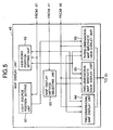
- Fig. 5 is a diagram showing the functional construction of the map display unit 45 shown in Fig. 4.
- a light source position setting unit 61 operates to store in its internal table a position parameter and an intensity parameter of a light source which are used to display a three-dimensional bird's-eye view map on the display 2.
- the position parameter and the intensity parameter of the light source are used to calculate the color of the surface of a map constituent which is drawn on the three-dimensional bird's-eye view map.
- the position of the light source may be set to the position of the sun or moon which is calculated on the basis of time information, date information and position information obtained from the GPS receiver 9.
- a predetermined position may be set as the light source position.
- the intensity of the light source may be varied in accordance with the weather or amount of sunshine which is estimated by a luminosity sensor mounted in the vehicle, or on the basis of weather information or the like which is obtained by the traffic information receiver 10. For example, if the weather is fine, the intensity of the light source is set to a high value, and if the weather is cloudy, the intensity of the light source is set to a low value.
- a view-point position setting unit 62 sets a view-point position for map viewing when a three-dimensional bird's-eye view map and a two-dimensional bird's-eye view map are displayed on the display 2.
- a map display method selecting unit 63 selects processing so that a map of a predetermined area which is requested to be displayed on the display 2 is displayed in a predetermined scale according to a display system of a map which is set into the input device 4 by the user or according to a display system of a map which is set as default. That is, if the two-dimensional map display is instructed, a two-dimensional map display unit 64 is activated. If the two-dimensional map bird's-eye view display is instructed, a two-dimensional map bird's-eye view display unit 65 is activated. If the three-dimensional bird's-eye view display is instructed, a three-dimensional map bird's-eye view display unit 66 is activated.
- map display units 64 to 66 generates a map drawing command, and transfers these commands to the graphics processor 51.
- the graphics processor 51 executes these commands to display a map on the display 2.
- the two-dimensional map display unit 64 forms, in a predetermined scale, a two-dimensional map in which the map constituents are arranged on the two-dimensional coordinate system with a predetermined point at the center thereof, and displays this map on the display 2. In this two-dimensional map, all the points on the map are represented in the same scale.
- the two-dimensional map bird's-eye view display unit 65 displays on the display 2 a projection map (two-dimensional bird's-eye view map) which is obtained by bird's-eye-viewing a two-dimensional map formed in a predetermined scale with a predetermined point at the center thereof from a view point set in the view-point position setting unit 62.
- the view-point position setting unit 62 preferably sets the view-point position to a position on the three-dimensional coordinate system, which is in the sky and far away from the current position obtained in the map matching unit 47 by a predetermined distance. Accordingly, map constituents adjacent to the view-point position are represented in more detail (in large scale) while map constituents far away from the view-point position are represented schematically (in small scale).
- the two-dimensional bird's-eye view map is formed by subjecting the two-dimensional data of the map constituents to the perspective transformation and then projecting the perspectively-transformed data onto the two-dimensional plane (projection plane) from a view point which is set by the view-point position setting unit 62.
- the perspective transformation will be described together with the description of the three-dimensional map bird's-eye view display unit 66.
- the three-dimensional map bird's-eye view display unit 66 displays on the display 2 a projection map (three-dimensional bird's-eye view map) which is obtained by bird's-eye-viewing a three-dimensional map formed with a predetermined point around the center thereof in a predetermined scale from a view point which is set in the view-point position setting unit 62.
- the view-point position setting unit 62 preferably sets the view-point position to a position on the three-dimensional coordinate system, which is in the sky and far away from the current position obtained in the map matching unit 47 by a predetermined distance. Accordingly, map constituents adjacent to the view-point position are represented in more detail (in large scale) while map constituents far away from the view-point position are represented schematically (in small scale). Further, a scene which is viewed from the set view point is displayed three-dimensionally.
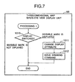
- Figs. 6 and 7 are flowcharts showing the operation of the three-dimensional map bird's-eye view display unit 66.
- vector data for specifying the shape of each of marks such as a current position, a destination, an intermediate place, an arrow for route guidance, etc., position information at which the mark concerned is displayed, and color information of the mark are stored in the internal buffer (1001).
- a two-dimensional shape and a three-dimensional shape may be set as the mark shape, and any one of them may be selected in accordance with the display system of the map.
- the data of marks stored in the internal buffer in step 1001 and the three-dimensional data of map constituents which are read in from the map storage unit 3 by the data reading unit 48 are subjected to the perspective transformation to obtain two-dimensional coordinate data when these marks and the map constituents are projected onto the two-dimensional plane (projection plane) from the view point set in the view-point position setting unit 62.
- step 1002 the coordinate data in the depth (line of sight) direction when these marks and the map constituents are viewed from the view point set by the view-point position setting unit 62 are obtained (step 1002).
- x' (x + T X )/(y • sin ⁇ + z • cos ⁇ + T Z )
- y' (y • cos ⁇ -z • sin ⁇ +T y )/(y • sin ⁇ + z • cos ⁇ + T Z )
- (x', y') represents a coordinate value on the projection plane after the perspective transformation
- (x, y, z) represents a coordinate value obtained by representing the coordinate value of each apex of the map constituents and the marks to be perspectively transformed in an object coordinate system
- (Tx, Ty, Tz) represents an offset value between a view-point coordinate system with the view point at the origin and the object coordinate system
- ⁇ represents an intersecting angle when the object coordinate system is rotated around the X-axis of the view-point coordinate system.
- step 1003 hidden-surface removal processing is performed to delete the data of portions located on the hidden surfaces of the map constituents and the marks which have been subjected to the perspective transformation in step 1002.
- the hidden surface is defined as the surface of a portion which is unseen when a three-dimensional map is viewed from a view point because it is located at the rear side of a map constituent or mark, or as the surface of a portion which is unseen when a three-dimensional map is viewed from a view point because it is hidden by a map constituent or mark located in front of the portion.
- the hidden-surface removal processing may be realized by various methods used in a computer graphics field such as a Z sort method, a Z buffer method, a scan line method, a ray casting method or the like.
- step 1003 when the Z sort method is applied to step 1003, the surfaces constructed by the respective apex of the map constituents and the marks which are subjected to the perspective transformation in step 1002, are rearranged in the depth (line of sight) direction. Thereafter, in step 1005 as described later, a map drawing command is generated so as to draw a map from the surface located at the deepest position (the surface which is farthest away from the view point).
- step 1003 the map constituents and the marks which are subjected to the perspective transformation in step 1002 are first shared to the pixels constituting the surfaces constructed by the respective apexes of the map constituents and the marks.
- the coordinate data in the depth (line of sight) direction of each of these pixels is determined, and another pixel which is located in front of the pixel concerned (i.e., is nearer to the view point than the pixel concerned) and has the same two-dimensional coordinate value as the pixel concerned is detected.
- step 1005 a map drawing command is generated so as to draw a map only from pixel data contained in a visible area from the view point.
- the map constituents and the marks which are perspectively transformed in step 1002 are arranged on a three-dimensional coordinate system which comprises two-dimensional coordinate axes for specifying the position on a projection plane and a coordinate axis for specifying the position in the depth (line of sight) direction.
- step 1005 a map drawing command is generated so as to draw the detected line segments.
- step 1004 the inner products of straight lines are calculated.
- the straight lines are the normal line of the surfaces constructed by the respective apexes of the map constituents and the marks which are perspectively transformed in step 1002, and the line connecting the surfaces constructed by the respective apexes and the light source position coordinate set in the light source position setting unit 61. Further, color information which is used when each surface is displayed in the three-dimensional map bird's-eye view display mode is determined on the basis of preset color information.
- the position and the intensity of the light source being used are preferably identical (fixed) among the map constituents and marks.
- step 1005 a map drawing command is generated to draw planes and lines so that the map constituents and the marks which are subjected to the hidden-surface removal processing in step 1003 are displayed according to the color information determined in step 1004.
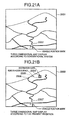
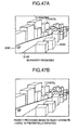
- the graphics processor 51 can display a three-dimensional bird's-eye view map as shown in Fig. 21A on the display 2. According to the processing of steps 1001 to 1005, however, a scene which is viewed from the view point is displayed as it is. Therefore, even map constituents and marks which are located on the hidden surface and whose information is requested by the user are not displayed on the display, and this is inconvenient for practical use. In order to solve this problem, the present invention uses the processing of steps 1006 to 1012.
- map constituents and marks which are requested by the user and are located in an invisible area (on the hidden surface) are selected from map constituents which are read out from the map storage unit 3 by the data reading unit 48 and marks which are set in step 1001.
- map constituents and the marks which are requested to be displayed by the user are those map constituents and marks which are directly instructed to be displayed through the input device 4 by the user , or which are preset to be displayed as default information. A judgment as to whether map constituents and marks are located in an invisible area will be described later.
- step 1007 on the basis of a display parameter set through the input device 4 by the user or a display parameter set as default, it is judged whether map constituents located in an invisible area selected in step 1006 are displayed. If the display parameter is set to a mode in which the map constituents in the invisible area are displayed, the processing goes to step 1008. On the other hand, the display parameter is set to a mode in which the map constituents in the invisible area are not displayed, the processing goes to step 1010.
- step 1008 the map constituents selected in step 1006 are subjected to display attribute alteration processing such as alteration of attributes, the perspective processing, etc. for the display on the display 2.
- display attribute alteration processing such as alteration of attributes, the perspective processing, etc. for the display on the display 2.
- the display attribute alteration processing will be described later.
- step 1009 a map drawing command is generated to draw the surfaces and lines constituting the map constituents concerned on the basis of the display attributes, etc. which are set in step 1008.
- a road 2005 leading to a destination, which is hidden by a mountain is displayed by a dotted line or the like, whereby information requested by the user can be provided.
- step 1010 in Fig. 7 on the basis of the display parameter set through the input device 4 by the user or the display parameter set as default, it is judged whether marks in an invisible area selected in step 1006 are displayed.
- step 1011 If the display parameter is set to a mode in which the marks in the invisible area are displayed, the processing goes to step 1011. On the other hand, it the display parameter is set to a mode in which the marks in the invisible area are not displayed, the flow shown in Figs. 6 and 7 is ended.
- step 1011 the display attribute alteration processing as described later is performed on the marks set in step 1001.
- step 1012 the map drawing command is generated to draw the surfaces and lines constituting the marks set in step 1001 in accordance with the display attribute, etc. set in step 1011. Accordingly, for example, in the three-dimensional bird's-eye view map shown in Fig. 21B, a destination mark 2004 which is hidden by a mountain and set in step 1001 is displayed, and thus information which is needed by the user can be provided to the user.
- Fig. 8 is a flowchart showing the mark setting processing.
- the display parameter which is set through the input device 4 by a user or the display parameter which is set as default is read out to judge whether the current position mark is set (step 1101).
- step 1102 the processing goes to step 1102 to set the position at which the current position mark is displayed, the predetermined two-dimensional or three-dimensional shape of the current position mark and the color information of the current position mark.
- the position information of the current position is determined by the current position calculator 46 and the map matching processor 47.
- step 1103 the display parameter which is set through the input device 4 by the user or is set as default is read out to judge whether a destination mark is set.
- step 1104 sets the position at which the destination mark is displayed, the predetermined two-dimensional or three-dimensional shape of the destination mark, and the color information of the destination mark.
- step 1105 the display parameter which is set through the input device 4 by the user or is set as default is read out to judge whether a guide direction mark is set.
- step 1106 sets the position at which the guide direction mark is displayed, the predetermined two-dimensional or three-dimensional shape of the guide direction mark, and the color information of the guide direction mark.
- step 1107 the display parameter which is set through the input device 4 by the user or is set as default is read out to see whether other display marks are displayed.
- a display mark representing accident information which is obtained by analyzing a signal received by the traffic information receiver 10 is used as one of the other display marks.
- step 1108 the processing goes to step 1108 to set the positions at which the other display marks are displayed, the predetermined two-dimensional or three-dimensional shape of each of the other display marks, and the color information of the other display marks.
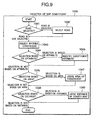
- Fig. 9 is a flowchart showing the map constituent selection processing.
- the display parameter which is set through the input device 4 by the user or is set as default is read out to judge whether a map constituent in connection with a road is selected from map constituents which are read out from the map storage unit 3 by the data reading unit 48.
- step 1042 If the map constituent in connection with the road is judged to be selected, the processing goes to step 1042. On the other hand, if no map constituent associated with the road is selected, the processing goes to step 1043.
- the judgment as to whether the map constituent is connected with the road is performed by referring to data which is read from the map storage unit 3 by the data reading unit 48 and used to specify the type of map constituent.
- step 1043 a map constituent which is partially or wholly located in an invisible area is selected from map constituents which are read from the map storage unit 3 by the data reading unit 48, and a mark which is partially or wholly located in the invisible area is selected from marks set in step 1001 of Fig. 6.
- the judgment as to whether the map constituent and the mark are located in the invisible area is performed as follows. For example, when the hidden-surface removal processing in step 1003 of Fig. 6 is performed by the Z buffer method, the coordinate data in the depth direction of pixels constituting the surface of the map constituent or mark concerned which is subjected to the hidden-surface removal processing are compared with the coordinate data in the depth direction of pixels constituting the surface of the map constituent or mark concerned before the hidden-surface removal processing.
- the map constituent (mark) concerned is judged to be located in the invisible area. If both are not coincident with each other, the pixel data of the map constituent (mark) concerned is partially or wholly substituted by the pixel data of a map constituent or the like which is located in front of (nearer to the view point than) the map constituent (mark) concerned, so that the map constituent (mark) is judged to be located in the invisible area.
- step 1044 the display parameter which is set through the input device 4 by the user or is set as default is read out to judge whether the selection of map constituents (or marks) on the basis of the attribute from the map constituents or marks selected in step 1043 is performed.
- step 1045 When it is judged that the selection of the map constituents (or marks) on the basis of a predetermined attribute is performed, the processing goes to step 1045. If this is not the case, the processing goes to step 1046.
- step 1045 map constituents (marks) based on the attribute, which is set through the input device 4 by the user or is set as default, is selected from the map constituents (marks) selected in step 1043.
- the data of the map constituent of the destination is selected from the map constituents which are read from the map storage device 3 by the data reading unit 48.
- the judgment as to whether the map constituent has a predetermined attribute is performed by referring to data specifying the type of map constituent which is read from the map storage unit 3 by the data reading unit 48.
- step 1046 the display parameter which is set through the input device 4 by the user or is set as default is read out to judge whether the selection of map constituents (marks) is performed on the basis of the area of a three-dimensional bird's-eye view map from the map constituents or marks selected in step 1043.
- step 1047 When it is judged that the map constituents (marks) located in a predetermined area of a three-dimensional bird's-eye view map are selected, the processing goes to step 1047. If this is not the case, the processing goes to step 1048.
- step 1047 map constituents or marks located in an area on a three-dimensional bird's-eye view map which is set through the input device 4 by the user or is set as default are selected from the map constituents or marks which are selected in step 1043.
- the judgment as to whether the map constituent (mark) is located in a predetermined area of the three-dimensional bird's-eye view map is performed on the basis of the two-dimensional coordinate data of the map constituents and marks which are obtained by the perspective transformation processing instep 1002 of Fig. 6.
- step 1048 the display parameter which is set through the input device 4 by the user or is set as default is read out to judge whether the selection of map constituents and marks is performed on the basis of the distance from the boundary line between a visible area and an invisible area from the map constituents or marks selected in step 1043.
- step 1049 When it is judged that the selection of the map constituents or marks within a predetermined distance from the boundary line is performed, the processing goes to step 1049. If this is not the case, the flow of Fig. 9 is ended.
- step 1049 those map constituents or marks which are located within a predetermined distance from the boundary line between the visible area and the invisible area, the distance being set through the input device 4 by the user, or is set as default, are selected from the map constituents or marks which are selected in step 1043.
- those map constituents or marks are selected which are located in an invisible area within a predetermined distance 2036 from the boundary line 2035 between the visible area and the invisible area.
- a destination mark 2004 located within a predetermined distance 2036 from the boundary line 2035 is displayed as shown in Fig. 21B. Accordingly, of the map constituents and marks in an invisible area, only information (map constituents and marks) which the user wants to see can be displayed. In addition, map constituents and marks which do not need to be displayed are omitted from a display map, so that the display map is made clear to see.
- the scan line method or the like may be used as a method for determining the boundary line between a visible area and an invisible area.
- the judgment as to whether the map constituent or mark is within a predetermined distance from the boundary line is performed by calculating the distance between the coordinate data in the depth (line of sight) direction of the map constituent or the mark and the coordinate data in the depth (line of sight) direction of the map constituent or the mark.
- Fig. 10 is a flowchart showing the road selection processing.
- map constituents which are partially or wholly located in an invisible area are selected from map constituents which are read from the map storage unit 3 by the data reading unit 48, and then map constituents in connection with a road are selected from the selected map constituents by referring to data which specify the types of the map constituents (step 1061).
- the display parameter which is set through the input device 4 by the user or is set as default is read out to judge whether the road selection from the roads selected in step 1061 is performed on the basis of the attribute (step 1062).
- step 1063 When it is judged that the road selection is performed on the basis of a predetermined attribute, the processing goes to step 1063. If this is not the case, the processing goes to step 1064.
- step 1063 a road having an attribute which is set through the input device 4 by the user or is set as default is selected from the roads selected in step 1061.
- step 1064 the display parameter which is set through the input device 4 by the user or is set as default is read out to judge whether the selection of a road to be connected to a road in a visible area is performed from the roads selected in step 1063.
- step 1065 If it is judged that a road to be connected to a road in a visible area is selected, the processing goes to step 1065. If not, the flow of Fig. 10 is ended.
- step 1065 a road to be connected to a road located in a visible area is selected from the roads selected in step 1061 or step 1063.
- the judgment as to whether the road is connected to a road located in a visible area can be performed, for example by determining the boundary line between the visible area and the invisible area in the same manner as the processing in step 1048 of Fig. 9, and then selecting a road traversing the boundary line from the roads selected in step 1061 or step 1063.
- step 1066 the display parameter which is set through the input device 4 by the user or is set as default is read out to judge whether the selection of a road located within a predetermined distance from the connection boundary between the road concerned and a road in a visible area from the roads selected in step 1065 is performed.
- step 1067 If it is judged that the road selection as described above is performed, the processing goes to step 1067. If not, the flow shown in Fig. 10 is ended.
- step 1067 in the same manner as the processing of step 1049 of Fig. 9, a road within the predetermined distance from the connection boundary with a road located in a visible area is selected from the roads selected in step 1065.
- a road which is located in an invisible area and connected to a road in a visible area, that is a road 2 is selected in step 1065. That is, a road 1 which is not connected to a road in a visible area is not selected.
- a road within a predetermined distance from the connection boundary with the road in the visible area that is, a road 2024 which is spaced from the road 2 by a distance A, is selected in step 1067.
- the display attribute of the road 2005 located on the hidden surface in step 1008 of Fig. 6 is altered, and the road 2005 is displayed by a predetermined distance.
- Figs. 11 and 12 are flowcharts showing the road attribute selection processing.
- the display parameter which is set through the input device 4 by the user or is set as default is read out to judge whether the selection of a road having a predetermined attribute from the roads selected in step 1061 is performed (step 1081).
- the predetermined attribute represents the type of road, such as a highway, a national road or the like.
- step 1082 a road having the predetermined attribute is selected.
- the judgment as to whether the road has the predetermined attributed is performed by referring to data for specifying the type of map constituent which is read from the map storage unit 3 by the data reading unit 48. With this processing, the display attribute of the road having the predetermined attribute in the invisible area in step 1008 of Fig. 6 is altered, so that this road is displayed on the display 2. Therefore, the user can identify the road having a predetermined attribute in an invisible area.
- the display parameter which is set through the input device 4 by the user or is set as default is read out to judge whether the selection of a road on which the vehicle runs from the roads selected in step 1061 is performed.
- the position information which is obtained by the current position calculator 46 and the map matching processor 47 is compared with the map information stored in the map storage unit 3 to determined a road on which the vehicle is running.
- step 1084 If it is judged that the selection of the road (current road) on which the vehicle is running is performed, the processing goes to step 1084. If not, the processing goes to step 1085.
- step 1084 the road on which the vehicle is running is selected from the roads selected in step 1061.
- a road on which the position obtained by the current position calculator 46 and the map matching processor 47 exists, and also which is located within a predetermined distance from the current position may be selected as the current road.
- the display attribute of the road on which the vehicle is running and which is located in an invisible area in step 1008 of Fig. 6 is altered, whereby the road is displayed on the display 2. Accordingly, the user can identify the road in the invisible area on which the vehicle is running.
- the display parameter which is set through the input device 4 by the user or is set as default is read out to judge whether the selection of a road for a guide route from the roads selected in step 1061 is performed.
- the road for a guide route is obtained by accessing the route storage unit 43 for storing a calculation result of an optimum route from the current position at the time the route calculation of the route calculator 42 is started to the destination.
- step 1086 When it is judged that the selection of the road for guide route is performed, the processing goes to step 1090 of Fig. 12.
- step 1086 the road for a guide route is selected from the roads selected in step 1061.
- the display attribute of the road for a guide route which is located in an invisible area in step 1008 of Fig. 6 is altered, so that the road is displayed on the display 2. Accordingly, the user can identify the road for a guide route in the invisible area.
- step 1090 of Fig. 12 the display parameter which is set through the input device 4 by the user or is set as default is read out to judge whether the a road having a traffic jam is selected from the roads selected in step 1061.
- the road having a traffic jam is determined by analyzing a signal which is received by the traffic information receiver 10.
- a radio wave beacon signal which is mounted on a road and adapted to modulate sub-microwave, or an optical beacon signal for modulating light waves may be used.
- step 1091 If it is judged that the road having traffic jam is selected, the processing goes to step 1091. If not, the processing goes to step 1092.
- step 1091 a road having traffic jam is selected from the roads selected in step 1061.
- the display attribute of the road having traffic jam in an invisible area in step 1008 of Fig. 6 is altered, so that the road is displayed on the display 2. Accordingly, the user can identify the road which has a traffic jam and is located in an invisible area.
- step 1092 the display parameter which is set through the input device 4 by the user or set as default is read out to judge whether a road which does not have a traffic jam is selected from the roads selected in step 1061.
- the road which does not have a traffic jam can be known by analyzing the signal received from the traffic information receiver 10. If it is judged that the road having no traffic jam is selected, the processing goes to step 1093. If not, the processing goes to step 1094.
- step 1093 a road having no traffic jam is selected from the roads selected in step 1061.
- the display attribute of a road which is in an invisible area and which has no traffic jam is altered, so that this road is displayed on the display 2. Accordingly, the user can judge whether the road in the invisible area does not have a traffic jam.
- step 1094 the display parameter which is set through the input device 4 by the user or is set as default is read out to judge whether a restricted road is selected from the roads selected in step 1061.
- the restricted road is known by analyzing a signal which is received by the traffic information receiver 10.
- a radio wave beacon signal which is mounted on a road and adapted to modulate sub-microwaves, or an optical beacon signal for modulating light waves may be used.
- step 1095 If it is judged that the restricted road is selected, the processing goes to step 1095. If not, the processing goes to step 1095.
- step 1095 the restricted road is selected from the roads selected in step 1061.
- the display attribution of the restricted road which is located in the invisible area in step 1008 in Fig. 6 is altered, so that the restricted road is displayed on the display 2. Accordingly, the user can identify the restricted road in the invisible area.
- step 1096 the display parameter which is set through the input device 4 by the user or is set as default is read out to judge whether a road which is not restricted is selected from the roads selected in step 1061.
- the road having no restriction is known by analyzing the signal received by the traffic information receiver 10. If it is judged that the restricted road is selected, the processing goes to step 1097. If not, the flow shown in Figs. 11 and 12 is ended.
- step 1097 the non-restricted road is selected from the roads selected in step 1061.
- the display attribute of the non-restricted road which is located in an invisible area in step 1008 of Fig. 6 is altered, so that this road is displayed on the display 2. Accordingly, the user can identify the non-restricted road in the invisible area.
- Fig. 13 is a flowchart showing the display attribute alteration processing.
- step 1021 a method for presenting map constituents or marks located in an invisible area are read out from the display parameter which is set through the input device 4 by the user or set as default.
- step 1022 When a through-vision display mode is specified, the processing goes to step 1022. If an attribute alteration display mode is specified, the processing goes to step 1023.
- step 1022 the map constituent in the invisible area which is selected in step 1006 of Fig. 6 is displayed in the through-vision display mode.
- the color of the map constituent in the invisible area which is to be displayed in the through-vision display mode so that it can be seen at predetermined transmittance is calculated and set on the basis of the color information of the map constituent which is determined in step 1004 and is to be displayed in the through-vision display mode, and the color information of a map constituent by which the map constituent in the invisible area is hidden.
- the color information of a map constituent which is requested to be displayed in the through-vision display mode is set to the source side while the color information of another map constituent by which the former map constituent is hidden is set to the destination side, and these map constituents are subjected to the ⁇ -blending processing at a predetermined transmittance (for example, 50% at the source side and 50% at the destination side) by using the equation (3), whereby the through-vision display can be performed.
- a predetermined transmittance for example, 50% at the source side and 50% at the destination side
- the same calculation is also usable when a target to be displayed in the through-vision display mode is a mark.
- the map drawing command is generated to draw the map constituent or mark in the invisible area which is selected in step 1006 of Fig. 6. Accordingly, the map constituent or mark located in the invisible area can be displayed in the through-vision display mode.
- step 1023 the display attribute of the map constituent or mark selected in step 1006 of Fig. 6 for the display 2 is altered.
- step 1024 according to the display parameter which is set through the input device 4 by the user or is set as default, it is judged whether a map constituent or mark in an invisible area is subjected to pattern alteration processing and then displayed.
- step 1025 When the pattern alteration processing is instructed in the display parameter, the processing goes to step 1025 to set an attribute so that the surfaces and lines constituting the map constituents or marks selected in step 1006 of Fig. 6 are displayed in a predetermined pattern.
- An example of a display in this case is shown in Fig. 21B.
- step 1026 on the basis of the display parameter which is set through the input device 4 by the user or is set as default, it is judged whether the map constituent or mark in the invisible area which is selected in step 1006 of Fig. 6 is displayed while the line width thereof is changed (step 1026).
- step 1027 When the change of the line width is instructed in the display parameter, the processing goes to step 1027 to set the attribute so that the line constituting the map constitute or mark selected in step 1006 of Fig. 6 is displayed so as to have a predetermined width.
- step 1028 on the basis of the display parameter which is set through the input device 4 by the user or is set as default, it is judged whether the color of the surface or line constituting the map constituent or mark in the invisible area which is selected in step 1006 of Fig. 6 is changed for display.
- step 1029 If the color change is instructed in the display parameter, the processing goes to step 1029 to set the attribute so that the surface or line constituting the map constituent or mark in the invisible area which is selected in step 1006 of Fig. 6 is displayed with a predetermined color.
- FIG. 21B A specific display example is shown in Fig. 21B. This is the case where the destination mark 2004 in the invisible area is displayed while its color is changed from the surrounding area.
- Fig. 14 is a flowchart showing the operation of the first modification of the three-dimensional bird's-eye view display unit 66.
- steps 1121 to 1124 is similar to the processing of steps 1001 to 1004 of Fig. 6, the processing of step 1125 is similar to the processing of step 1006 of Fig. 6, and the processing of step 1129 is similar to the processing of step 1005 of Fig. 6. Accordingly, the detailed description on the processing of steps 1121 to 1125 and the processing of step 1129 is omitted.
- step 1126 the display parameter which is set through the input device 4 by the user or is set as default is read out to judge removal or non-removal of a map constituent which is located in front of (nearer to the view point than) a map constituent or mark selected in step 1125 so as to cover the map constituent or mark selected in step 1125.
- step 1127 If the front map constituent is removed, the processing goes to step 1127, and If not, the processing goes to step 1126a.
- step 1126a the display parameter which is set through the input device 4 by the user or is set as default is read out to judge whether the map constituent or mark selected in step 1125 is displayed on the display 2. If the map constituent or mark is judged to be displayed, the processing goes to step 1126b. If not, the processing goes to step 1129.
- step 1126b the map constituent located in front of the map constituent or mark selected in step 1125 is specified (the map constituent thus specified is hereinafter referred to as "front map constituent").
- the two-dimensional coordinate data on the two-dimensional plane (projection plane) of each of the map constituents and marks obtained through the perspective transformation processing in step 1122 are checked to extract a map constituent which is overlapped with the map constituent or mark selected in step 1125 on the projection plane.
- the coordinate data in the depth (line of sight) direction of the map constituent or mark selected in step 1125 are compared with the coordinate data in the depth (line of sight) direction of the extracted map constituent, and if the extracted map constituent is located in front of (nearer to the view point than) the map constituent or mark selected in step 1125, the extracted map constituent is specified as the front map constituent.
- step 1126b out of the coordinate data of the map constituents and the marks which are subjected to the perspective transformation in step 1122, the coordinate data in the depth (line of sight) direction of the map constituent or mark selected in step 1125 are rewritten so that the map constituent or mark concerned is located in front of the front map constituent. Thereafter, the processing of steps 1123 and 1124 is performed again.
- the graphics processor 51 can display on the display 2 such a three-dimensional bird's-eye view map that the map constituent or mark which is requested to be displayed by the user is drawn in front of the front map constituent.
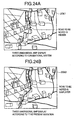
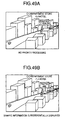
- a route guidance mark 2084 is displayed in front of a building 2082 and a tree 2083 which originally stand in front of the route guidance mark 2086.
- step 1127 in the same manner as the above step 1126b, a front map constituent which is originally located in front of the map constituent or mark selected in step 1125 is specified, and then the three-dimensional data of the front map constituent is removed from the three-dimensional data of the map constituents which are read in from the map storage unit 3 by the data reading unit 48.
- the front map constituent specify/remove processing will be described later.
- step 1127 the processing of steps 1122 to 1124 is performed again on the basis of the three-dimensional data of the map constituents which are read in from the map storage unit 3 and from which the three-dimensional data of the front map constituents are removed, and the data of the mark set in step 1121.
- the graphics processor 51 can display on the display 2 such a three-dimensional bird's-eye view map that the map constituent or mark which is requested to be displayed by the user is displayed while the front map constituents thereof are removed.
- the display 2 such a three-dimensional bird's-eye view map that the map constituent or mark which is requested to be displayed by the user is displayed while the front map constituents thereof are removed.
- front map constituents such as a building and a tree by which the route guidance mark 2086 is hidden are removed, and the route guidance mark 2086 which is needed by the user is displayed on the display 2 is displayed on the display 2.
- step 1128 the information on the frontmost front map constituents is displayed in place of the front map constituents which are removed in step 1127.
- Fig. 15 is a flowchart showing the front map constituent information display processing.
- step 1141 the display parameter which is set through the input device 4 by the user or is set as default is read out to judge whether the ground plane occupied by the map constituent removed in step 1127 of Fig. 14 is displayed on the display 2.
- step 1142 If the ground plane is judged to be displayed, the processing goes to step 1142. If not, the processing goes to step 1143.
- step 1142 the ground plane of the removed front map constituent is obtained, and the ground plane is displayed with a predetermined attribute (color, pattern, etc.) on the display 2.
- the graphics processor 51 can display the ground plane occupied by the front map constituent on the display 2.
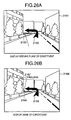
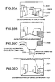
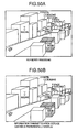
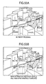
- FIG. 26A A specific display example is shown in Fig. 26A.
- the building 2082 and the tree 2083 by which the display-requested guide mark is covered and hidden are deleted from the three-dimensional bird's-eye view map shown in Fig. 25A, and the ground plane 2163 representing the existence of the building is displayed in an area where the building exists.
- Such a display enables the user to know whether the deleted map constituent exists and where it exists, and prevents the user from not recognizing something due to the map display with the front map constituent being deleted from the map.
- step 1143 the display parameter which is set through the input device 4 by the user or is set as default is read out to judge whether the name of the front map constituent removed in step 1127 of Fig. 14 is displayed on the display 2.
- step 1144 the ground plane of the front map constituent which is removed in the same manner as the processing of step 1142 is determined, and the mark is set so that the name of the front map constituent is displayed in the neighborhood of the ground plane.
- the name of the front map constituent is determined on the basis of the type of the front map constituent which is read in from the map storage unit 3 by the data reading unit 48.
- the graphics processor 51 can display the name of the front map constituent in the neighborhood of the position which is originally occupied by the front map constituent.
- FIG. 26B A specific display example is shown in Fig. 26B. This is a case where the building 2082 and the tree 2083 by which the display-requested guide mark is covered and hidden are deleted from the three-dimensional bird's-eye view map, and the ground plane 2166 representing the existence of the building and the name 2167 of the building are displayed in an area where the building stands.
- the user can readily know what the deleted map constituent is. Therefore, the user can be prevented from not recognizing something caused by the deletion of the map constituent from the map.
- Fig. 16 is a flowchart showing the front map constituent specify/remove processing.
- step 1161 the attribute of the front map constituent which is specified is identified. If the attribute represents a road, the processing goes to step 1166. If not, the processing goes to step 1163.
- the judgment of the attribute is performed on the basis of the data specifying the type of the front constituent which is read in from the map storage unit 3 by the data reading unit 48.
- step 1162 the three-dimensional data of the front map constituent are removed from the three-dimensional data of the map constituents which are read in from the map storage unit 3 by the data reading unit 48, and then the processing goes to step 1163.
- step 1166 the overlap amount between the map constituent or mark selected in step 1125 of Fig. 14, and a road which is located in front of (nearer to the view point than) the map constituent or mark and covers the map constituent or mark is determined.
- the detection of the overlap amount is performed on the basis of the two-dimensional coordinate data on the projection plane of the map constituent or mark selected in step 1125 of Fig. 14 and the two-dimensional coordinate data on the projection plane of the road which is the front map constituent.
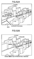
- the map constituent or mark selected in step 1125 of Fig. 14 is estimated to be overlapped with the road corresponding to the front map constituent because it is at a multilevel crossing or the like. Accordingly, in such a case, it is unnecessary to remove the road corresponding to the front map constituent, and thus the flow of Fig. 16 is ended. On the other hand, if the overlap amount is above the predetermined value, the processing goes to step 1167.
- a removing range is determined for the road which is the front map constituent of the map constituent or mark selected in step 1125 of Fig. 14.
- the removing range may be limited to a place which is located within a predetermined distance from the current position which is determined by the map matching processor 47. Accordingly, a road which is overlapped with an area to be originally noted is removed, so that the user can obtain more information in the vicinity of the current position.
- step 1168 the three-dimensional data of a portion in an area which is a part of the road (i.e., the front map constitute) and located within a predetermined distance from the current position (an area which is specified on the basis of the latitude and longitude values) are removed from the three-dimensional data of the map constituents which are read in from the map storage unit 3 by the data reading unit 48. Thereafter, the processing goes to step 1163.
- step 1163 the processing of steps 1122 to 1124 of Fig. 14 is performed again on the basis of the three-dimensional data of the map constituents and the marks which are obtained through the processing of steps 1162 or 1168.
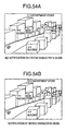
- the graphics processor 51 can display on the display 2 a three-dimensional bird's-eye view map from which the front map constituent is removed and in which the map constituents and the marks which are requested to be displayed by the user are drawn.
- the processing of steps 1122 to 1124 is performed again on the basis of the three-dimensional data of the map constituents and the marks obtained through the processing of step 1168, the road corresponding to the front map constituent of the mark 2104 is displayed while a predetermined portion thereof is deleted as shown in Fig. 27B. Therefore, the user can obtain the three-dimensional bird's-eye view map having the detailed information on the peripheral portion of the current position.
- Fig. 17 is a flowchart showing the operation of the second modification of the three-dimensional map bird's-eye view display unit 66.
- steps 1261 to 1264 is similar to the processing of steps 1001 to 1004 shown in Fig. 6, the processing of step 1265 is similar to the processing of step 1006 of Fig. 6, and the processing of step 1268 is similar to the processing of step 1005 of Fig. 6.
- step 1266 it is judged whether any map constituent or mark in the invisible area is selected in step 1265. If it is selected, the processing goes to step 1267. If not, the processing goes to step 1268.
- step 1267 an instruction is output to the view-point position setting unit 62 to reset the view-point position.
- the resetting is performed so that the height position of the view point is increased, that is, the coordinate value in the height (Z) direction of the view point is increased.
- the resetting is performed so that the view point is made to approach the map constituent or mark selected in step 1265.
- steps 1262 to 1266 By using the view-point position information thus reset, the processing of steps 1262 to 1266 is performed again. The processing of steps 1262 to 1266 is repeated until no map constituent or mark in the invisible area is selected in step 1265.
- the graphics processor 51 can display on the display 2 a three-dimensional bird's-eye view map which is obtained by viewing the map from the view-point position at which the map constituent or mark which is requested to be displayed by the user can be viewed. Accordingly, more information which the user needs can be provided at all times.
- Fig. 18 is a flowchart showing the operation of the third modification of the three-dimensional map bird's-eye view display unit 66.
- steps 1181 to 1184 is similar to the processing of steps 1001 to 1004, the processing of steps 1185 is similar to the processing of step 1006 shown in Fig. 6, and the processing of step 1189 is similar to the processing of step 1005 shown in Fig. 6. Accordingly, the detailed description of the processing of steps 1181 to 1185 and step 1189 is omitted.
- step 1186 it is judged whether any map constituent or mark in an invisible area is selected in step 1185. If any map constituent or mark is selected, the processing goes to step 1187. If this is not the case, the processing goes to step 1189.
- step 1187 the position at which an overlap frame (window) is displayed on the display frame of the display 2 is determined.
- the current position is usually displayed at the lower side of the display center while the destination is displayed at the upper side of the display center, and thus the position of the window is preferably set to an area other than the display areas of the current position and the destination.
- the window area is preferably set to a place which corresponds to an upper right or upper left side of the display frame of the display 2 and has an area which is equal to a quarter or less of the whole area of the display frame of the display 2.
- the following method may be used to set another preferable window display position. That is, a half of the display frame is set as a window, and the original display frame is shifted so that the center portion on the other half display frame is coincident with the center portion of the original three-dimensional map which has been displayed before the window is displayed.
- step 1188 the three-dimensional map bird's-eye view display unit 66, the two-dimensional map display unit 64 and the two-dimensional map bird's-eye view display unit 65 are instructed so that a map based on a predetermined map representation method is displayed in the window for which the display position is set.
- Fig. 19 is a flowchart showing the operation of the map display instruction processing.
- step 1201 the display parameter which is set through the input device 4 by the user and is set as default is read out to judge whether a two-dimensional map is displayed in the window.
- step 1202. If the two-dimensional map is displayed, the processing goes to step 1202. If no so, the processing goes to step 1204.
- step 1202 an area for the two-dimensional map to be displayed in the window is set.
- an area of the three-dimensional map which is the base of the three-dimensional bird's-eye view map displayed on the display 2 may be selected as the area.
- step 1203 the two-dimensional map display unit 64 is activated to generate a map drawing command so that the two-dimensional map contained in the display area set in step 1202 is displayed in the window set in step 1189 of Fig. 18.
- the three-dimensional map bird's-eye view display unit 66 goes to step 1187 of Fig. 18 to generate a map drawing command of a three-dimensional bird's-eye view map.
- the graphics processor 51 can display the two-dimensional in the window 2123, and display the three-dimensional bird's-eye view map on a display frame 2121 other than the window on the display 2 as shown in Fig. 28A.
- the user can be provided with more desired information. Therefore, the user can obtain from the two-dimensional map the map information on the invisible area which is an obstacle in the three-dimensional map bird's-eye view display, so that visibility (easiness of recognition) and operability can be more enhanced.
- step 1204 the display parameter which is set through the input device 4 by the user or is set as default is read out to judge whether the two-dimensional bird's-eye view map is displayed in the window.
- step 1205 If the two-dimensional bird's-eye view map is displayed, the process goes to step 1205, If this is not the case, the processing goes to step 1207.
- step 1205 the area of the two-dimensional map serving as the base of the two-dimensional bird's-eye view map to be displayed on the window, and the view-point position from which the two-dimensional map is viewed are set .
- the area and the view-point position may be set so as to be coincident with the area of the three-dimensional map serving as the base of the three-dimensional bird's-eye view map to be displayed on the display 2 and the view-point position thereof, respectively.
- the display areas of the three-dimensional bird's-eye view map and the two-dimensional bird's-eye view map on the display 2 are coincident with each other.
- the setting of the view-point position is performed by the view-point position setting unit 62.
- step 1206 the two-dimensional map bird's-eye view display unit 65 is activated to generate the drawing command so that the two-dimensional bird's-eye view map obtained by viewing the two-dimensional map contained in the display area set in step 1205 from the view-point position set in step 1205 is displayed on the window set in step 1189 of Fig. 18.
- the three-dimensional map bird's-eye view display unit 66 goes to step 1187 of Fig. 18 to generate the map drawing command for the three-dimensional bird's-eye view map.
- the graphics processor 51 can display the two-dimensional bird's-eye view map in the window 2126 as shown in Fig. 28B, and display the three-dimensional bird's-eye view map on a display area 2124 other than the window on the display 2. Therefore, the user can obtain the map information in the invisible area which is an obstacle in the three-dimensional display mode, from the two-dimensional bird's-eye view map in which no invisible area occurs, so that visibility (easiness of recognition) and operability can be more enhanced.
- step 1207 the display parameter which is set through the input device 4 by the user or is set as default is read out to judge whether the three-dimensional bird's-eye view map is displayed in the window. If the three-dimensional bird's-eye view map is displayed, the processing goes to step 1208, If this is not the case, the flow of Fig. 19 is ended.
- step 1208 the display area of the three-dimensional bird's-eye view map to be displayed in the window and the view-point position are set.
- the view-point position of the three-dimensional bird's-eye view map to be displayed in the window is preferably set to a position which is different from the view-point position of the three-dimensional bird's-eye view map which is displayed out of the window of the display 2.
- the view point is preferably set to any position at which the map constituent or mark in the invisible area which is selected in step 1185 of Fig. 18 can be viewed.
- the setting of the view-point position is performed in the view-point position setting unit 62.
- step 1209 in the same manner as the processing of steps 1001 to 1005, the three-dimensional bird's-eye view map obtained by viewing the three-dimensional map contained in the display area set in step 1208 from the view-point position set in step 1208 is displayed in the window set in step 1187 of Fig. 18. Thereafter, the processing goes to step 1189 of Fig. 18 to generate a map drawing command for the three-dimensional bird's-eye view map to be displayed on a display frame other than the window on the display 2.
- the graphics processor 51 displays the three-dimensional bird's-eye view map in the window on the display 2, and also displays the three-dimensional bird's-eye view map on the display frame other than the window of the display 2. Accordingly, in the three-dimensional bird's-eye view map, the user can obtain map information which is viewed from plural view-point positions, and thus the visibility (easiness of recognition) and the operability can be more enhanced.
- Fig. 20 is a flowchart showing the operation of the fourth modification of the three-dimensional map bird's-eye view display unit 66.
- steps 1221 to 1224 is basically similar to the processing of steps 1001 to 1004 of Fig. 6, and the processing of step 1227 is basically similar to the processing of step 1005 shown in Fig. 6. Accordingly, the detailed description of the processing of steps 1221 to 1224 and step 1227 is omitted from the following description.
- step 1225 it is judged whether the current position determined by the current position calculator 46 and the map matching processor 47 is not covered and hidden by a map constituent located in front of (nearer to the view point than) the current position.
- step 1227 If the current position is judged to be visible, the processing goes to step 1227. If this is not the case, the processing goes to step 1226.
- step 1226 the three-dimensional map bird's-eye view display unit 66, the two-dimensional map display unit 64 or the two-dimensional map bird's-eye view display unit 65 is instructed to display a map based on a predetermined map representation method on the display screen of the display 2.
- step 1226 is identical to that of step 1186 of Fig. 19 except that the map based on the predetermined map representation method is displayed over the overall display frame (screen) of the display 2 in place of the window. That is, even if the current position is hidden by a mountain 2143 located in front of (nearer to the view point than) a vehicle position mark 2142 as shown in Fig. 29A, by instructing the two-dimensional map bird's-eye view display unit 65 to display a two-dimensional bird's-eye view map on the screen of the display 2, the display is switched to display the two-dimensional bird's-eye view map as shown in Fig. 29B. Therefore, the visibility (recognition) and operability of the map can be more enhanced.
- the two-dimensional map display unit 64, the two-dimensional map bird's-eye view display unit 65, the three-dimensional map bird's-eye view display unit 66, and the map display method selection unit 63 for selecting any display unit from the display units are provided as the map display units 45.
- any type map display unit may be used insofar as it can display at least a three-dimensional bird's-eye view map on the screen of the display or the like.
- a display frame of a navigation device to which the second embodiment of the present invention is applied.
- Fig. 30 shows an image of on the display frame of the navigation device which is subjected to the processing according to the second embodiment of the present invention.
- reference numeral 3021 represents a display frame of a monitor or the like
- reference numerals 3022 to 3026 represent buildings such as apartment houses, hotels, etc.
- reference numeral 3027 represents a road.
- the map contains geographical features such as mountains, rivers, etc. as well as the buildings and roads as described above, and these map constituents are collectively referred to as "object”.
- character information is displayed in an object display area (an area where an object is actually displayed on the display frame) corresponding to the character information.
- character information such as ⁇ -building", " ⁇ -apartment house”, etc. are displayed in the corresponding object display areas for the objects 3022 to 3025. Further, in this embodiment, if it is judged that any character information cannot be displayed in an object display area, the character information is displayed in the neighborhood of the corresponding object.
- the character information " ⁇ -hospital" is displayed with a leader line in the neighborhood of the object 3026.
- any character information can be displayed at the position at which the relation with the object corresponding to the character information can be kept as shown in Fig. 30.
- Objects are arranged on the world coordinate system on the basis of map data base in which three-dimensional information of the objects are stored. Subsequently, the objects on the world coordinate system are subjected to affine transformation processing to arrange the objects on a view-point coordinate system in which the view-point position is set as the origin and the view-point direction is set on the Z axis.
- the view-point position is set on the basis of an instruction of the user or of the current position (vehicle position) of a mobile in which the navigation device of this embodiment is mounted.
- the objects on the view-point coordinate system are subjected to the perspective transformation processing to arrange the objects on a screen coordinate system.
- the hidden-surface removal processing such as the Z buffer method or the like is performed to form a projection map which would be obtained by viewing the objects arranged on the world coordinate system from the set view-point position.
- the projection map thus formed is stored into a memory or the like as two-dimensional image data comprising plural pixel data which are arranged in a matrix form. Each of the pixel data is added with identification information of an object which is represented by the pixel data concerned.
- a series of processing as described above is performed by using various three-dimensional processing techniques of computer graphics .
- Fig. 31 is a flowchart showing character display processing of the second embodiment according to the present invention
- Figs. 32A and 32B are diagrams supplementing the flow shown in Fig. 31.
- an object which is displayed in the display frame 3021 and has character information is detected (step 4011).
- a judgment as to whether an object is displayed in the display frame 3021 is made by identifying the identification information of the object of the pixel data stored in a memory or the like.
- a judgment as to whether the object has character information is made as follows. That is, the three-dimensional information of each object is added with information on the presence or absence of character information, and then stored in the map data base. In this case, the above judgment can be performed by reading out the three-dimensional information of the object from the map data base and checking the information on the presence or absence of the character information which is added to the three-dimensional information.
- step 4012 a display area on the display frame of the object detected in step 4011 is determined (step 4012).
- the pixel data of the object detected in step 4011 is detected from the two-dimensional image data stored in the memory or the like, and the display area of the object is determined on the basis of the position of the pixel data on the two-dimensional image data.
- the display area S of an object 3022 detected in step 4011 is determined. For the determination of the display area S, it does not need to detect all the pixel positions occupied by the object 3022.
- the display area S may be specified by detecting the maximum position and minimum position in the horizontal direction (X) and the maximum position and minimum position in the vertical direction (Y) of the pixel positions occupied by the object 3022.
- step 4013 the character information corresponding to the object detected in step 4011 is read out from the storage unit in which the character information is stored (step 4013).
- the character information of the object is stored in the map data base, and as shown in Fig. 32C, the character information " ⁇ -building" of the object 3022 is read out from the map data base.
- the display area of the character information is set within the display area of the object (step 4014).
- the setting of the display area of the character information will be described later.
- the display layout of the character information is determined so that the character information is accommodated within the display area of the character information set in step 4014 (step 4015).
- step 4011 of Fig. 31 When an object as shown in Fig. 34A is detected from the display frame in step 4011 of Fig. 31, the display area S of the object as shown in Fig. 34B is obtained. In step 4041, xmax, xmin, ymax, ymin of the display area S is calculated.
- a rectangle ABCD surrounded by xmax, xmin, ymax, ymin which are calculated in step 4041 is introduced (step 4042) to obtain intersection points A' and C' between a diagonal line connecting the apexes A and C which are not contained in the display area S, and sides fa and fc which constitute a par of the frame of the display area S and are intersected to the diagonal line (step 4043).
- Fig. 33 is merely an example of the setting processing for the character information display area. Any processing may be used insofar as it can set the display area of the character information within the display area of the object like the processing of step 4014 shown in Fig. 31.
- step 4015 of Fig. 31 the setting of a display layout of character information
- Fig. 35 is a flowchart showing an embodiment of the layout setting method of character information
- Figs. 36A-36C are diagrams supplementing the flow shown in Fig. 35.
- the display area Sc of the character information which is determined in the flow of Fig. 33 is shown in Fig. 36A.
- the lateral size and longitudinal size of the display area Sc are represented by Xc and Yc respectively.
- Fig. 36B The character information " ⁇ -building" read out from the map data base or the like in step 4013 of Fig. 31 is shown in Fig. 36B.
- the character size (dx, dy) of the character information is set as show in Fig. 36B (step 4061).
- the character size is set to be large to the extent that the user can recognize characters sufficiently.
- step 4064 it is judged whether the character information can be displayed in the character display area Sc (n ⁇ M1 ⁇ M2) (step 4064).
- the character information is set to be developed in the character display area Sc in the display layout of the character information which is set in steps 4061 to 4063 (step 4065).
- the display area of the character information is reset so that the character information is developed in the neighborhood of the display area of the object in the display layout of the character information which is set in steps 4061 to 4063 (step 4066).
- FIG. 36C A display example in which the character information is developed in the character display area Sc is shown in Fig. 36C.
- the character information is developed at M2 (the number of characters) per line and over M1 lines in the character display area Sc of X in longitudinal size and Y in lateral size.
- the method of setting the display area Sc of the character information within the display area S of the object and developing the character information in the display area Sc In order to further limit the display position, a method for calculating the center of gravity of the display area S of the object and developing the character information so that the display area of the character information is overlapped with the center of gravity, or other methods may be used.
- Fig. 37 is a flowchart showing a modification of the layout setting method of the character information shown in Fig. 35.
- step 4015 shown in Fig. 31 (the setting of the display layout of the character information) is expanded to develop and display the character information within the display area of the object as much as possible.
- step at which the same processing as the flowchart of Fig. 35 is performed is represented by the same reference numeral, and the detailed description thereof is omitted.
- step 4064 if it is judged in step 4064 that the character information cannot be displayed within the character display area Sc, it is judged whether the display attribute of characters such as character size/aspect/character interval/line space, etc. can be changed (step 4081).
- the change of the display attribute of characters suffer some restrictions because the characters are much small and thus illegible, for example. Therefore, in consideration of a human artificial problem, a prescribed restriction value is beforehand set to the change of the display attribute of characters.
- step 4081 If it is judged in step 4081 that the display attribute can be changed, the display attribute of characters is changed (step 4082). On the other hand, If this is not the case, it is given up that the character information is attempted to be developed within the display area of the object, and the processing goes to step 4066.
- step 4066 shown in Figs. 35 and 37 (the display area of the character information is set again in the neighborhood of the display area of the object) will be described.
- Fig. 38 is a flowchart showing an embodiment of the processing of developing the character information in the neighborhood of the display area of the object
- Fig. 39 is a diagram supplementing the flow shown in Fig. 38.
- step 4091 the respective apex coordinates of the rectangle ABCD which are calculated in step 4042 of Fig. 33, that is, the coordinate of the A point (xmin, ymax), the coordinate of the B point (xmax, ymax), the coordinate of the C point (xmax, ymin) and the coordinate of the D point (xmin, ymin) are referred to (step 4091).
- a display area (x, y) in which character information can be displayed in the display layout set in steps 4061 to 4063 of Fig. 35 or 37 is set to an area which satisfies the following inequalities: x ⁇ xmin, x>xmax, y ⁇ ymin, y>ymax (an area indicated by oblique lines in Fig. 39) (step 4092).
- the display area (x, y) of character information may be basically set to any position insofar as it is out of the display area of the corresponding object.
- the character information is set so that it is developed within the character display area (x, y) in the above display layout (step 4093). With this processing, the flow shown in Fig. 38 is ended.
- the character information is preferably displayed with a leader line or a leader line having a frame surrounding the character information (like a balloon of a cartoon) in order to show the connection between the character information and the corresponding object.
- the display area for the character information of an object is set on the basis of the display area for the object concerned on the display frame 3021.
- the character information can be displayed at the position where it can be easily seen in accordance with the variation of the object.
- Fig. 40 is a flowchart showing the character display processing of a third embodiment according to the present invention.
- Figs. 41A-41D are diagrams supplementing the flow of Fig. 40.
- Fig. 41A is an outlook diagram when an object 3121 is viewed from a view-point position 3122 of Fig. 41C
- Fig 41B is an outlook diagram when the object 3121 is viewed from a view-point position 3123.
- the view-point position 3123 is located at a position which is obtained by moving the view point at the view-point position 3122 so that the distance between the view point and the center of the object 3121 is set to a substantially fixed value.
- the object 3121 is regarded as an object to be noted by the user because the view point is moved around the object 3121. In this case, when the display position of the character information of the object 3121 is varied, the operator may feel confused.
- the display area of the character information " ⁇ -building" of the object 3121 is kept at the coordinate position at the initial time when the movement of the view point is started.
- step 4111 it is judged whether the view point is moved with an object located in the display frame at the center while keeping the distance between the object and the view point to a substantially fixed value.
- a judgment as to whether the distance between the view point and the object is substantially fixed can be performed, for example, by storing the distance from the view point in the view-point coordinate system to each object and comparing the thus-stored distance with the previously-stored distance when the three-dimensional map is renewed due to the movement of the view point.
- step 4111 If it is judged that the view point is judged to be moved in step 4111, the character information of the object is excluded from targets which will be renewed in the character display processing (the processing of steps 4011 to 4016 shown in Fig. 31) performed later (step 4112).
- the display area of the object is gradually moved due to the movement of the view point, it is considered that the display area of the character information is kept at the coordinate position at the initial time when the movement of the view point is started.
- steps 4011 to 4016 shown in Fig. 31 is not performed to renew the character display processing unless the character information " ⁇ -building" which is set when the object is displayed at the position 3121 gets out of the display area 3125 of the object due to the movement of the view point (step 4113).
- the display area of the character information of the object is set again so that it keeps the initial display position at the time when the movement of the view point is started when the renewal is performed. Therefore, the display position of the character information of the object which is noted by the user can be prevented from varying minutely.
- Fig. 42 is a flowchart showing the processing of the fourth embodiment according to the present invention
- Figs. 43A, 43B and 43C are diagrams supplementing the flow shown in Fig. 42.
- the display area of the character information is set on the basis of the display area of the object to be actually displayed on the frame, that is, the projection map which has been subjected to the hidden-surface removal processing.
- the display area of the character information may be also set on the basis of the occupation area on the XY plane of an object on the screen coordinate system before the hidden-surface removal processing is performed (a state where no consideration is taken on the overlap between objects).
- the display area of character information is set on the basis of the occupation area of the XY plane of an object on the screen coordinate system before the hidden-surface removal processing is performed, with respect to the display area of character information having the above problem, the display area of the character information is set again on the basis of the display area of the object to be actually displayed on the frame.
- the display area of the character information within the display frame is basically set according to the same manner as the processing of steps 4011 to 4016 shown in Fig. 31 as shown in Fig. 42 (step 4131).
- step 4012 the occupation area of the XY plane of the object on the screen coordinate system is detected, and in step 4013 the display area of the character information is set on the basis of the occupation area of the object.
- step 4132 it is judged whether the object for which the display area of the character information is disposed at the position where it is hidden by another object located in front of the former object on the display frame 3021.
- This judgment can be performed by referring to the Z coordinate value of the object on the screen coordinate system.
- an occupation area of the object which is not hidden by the front object, that is, a display area Sc' of the object which is actually displayed on the frame is detected (step 4133).
- the display area of the character information and the display layout are set in the same manner as the processing of steps 4014 to 4015 shown in Fig. 3 (step 4234).
- the overlap between the character information of an object and the other objects can be avoided as shown in Fig. 43B.
- the above processing of steps 4131 to 4134 is repetitively performed on all the character information within the display frame 3021 (step 4135).
- the flow shown in Fig. 35 or 37 is executed to move the display position of the character information to a position in the neighborhood of the object 3142 as shown in Fig 43C.
- Fig. 44 is a flowchart showing an example of the processing of step 4133 shown in Fig. 42
- Fig. 45 is a diagram supplementing the flow of Fig. 44.
- the occupation areas 3161 and 3162 on the XY plane of the objects 3141 and 3142 on the screen coordinate system are first calculated as shown in Fig. 45 (step 4151).
- the contact points 3163 and 3164 of the occupation areas 3161 and 3162 are determined (step 4152), and an area containing the contact points 3163 and 3164 as the apexes thereof is set as the display area Sc' of the object 3142 (step 4153).
- Fig. 46 is a flowchart showing the processing according to the fifth embodiment according to the present invention.
- the fifth embodiment if the character information of an object is overlapped with another object or character information when the character information is disposed in the neighborhood of the corresponding object in the second and third embodiments, or if the overlap between objects is detected in the fourth embodiment, it is judged which character information (or object) is preferentially displayed to delete the display of one of the character information concerned and the other character information (object) or display them while overlaid on each other in accordance with the priority order.
- the display area and display layout of the character information are set in accordance with steps 4011 to 4016 shown in Fig. 31, or step 4131 shown in Fig. 42 (step 4171).
- step 4172 it is judged whether the character display area of the character information concerned is located at such a position that it is overlapped with another object located in front of the object corresponding to the character information or overlapped with the display area of the character information of another object (step 4172).
- step 4173 it is judged whether there is any preferential display instruction/non-preferential display instruction in the overlapped character information or object which is overlapped with the character display area concerned.
- This instruction may be directly set by the user, or in consideration of safety under running, it may be automatically set by the system side to which this embodiment is applied.
- the attribute (for example, the type of the building, the type of the road, etc.) of the object is referred to (step 4174).
- the attribute of the object can be identified by referring to the character information added to the object, for example.
- the priority is set on the basis of steps 4171 and 4172, and a nesting management is performed from appendant (character) information or object having a lower priority, so that the appendant (character) information or object having the highest priority is displayed on the display frame.
- the user may select the appendant information or object on the display frame by using a pointing device such as a mouse, a pen or the like to switch the appendant information or object to be displayed on the display frame in a toggle mode (step 4175).
- the display area of the character information concerned is set at such a position that it is not overlapped with another object located in front of the object corresponding to the character information concerned on the display frame or the display area of the character information of the other object (step 4176).
- the display layout of the character information is set on the basis of the display area of the character information thus set (step 4177).
- Figs. 47A and 47B to 54A and 54B show images on the display frame when the preferential display processing shown in the flowchart of Fig. 46 is performed. In all the cases, it is assumed that streets having many buildings standing in a row are displayed in a bird's-eye view display mode.
- a display frame when the preferential processing is not performed is shown in Figs.47A to 54A
- a display frame when the preferential processing is performed is shown in Figs. 47B to 54B.
- reference numeral 3181 represents the vehicle position (current position) of a vehicle in which the navigation device of this embodiment is mounted
- reference numeral 3182 represents a road
- reference numeral 3183 represents a structure such as a building or the like.
- Figs. 47A and 47B show a case when the display preferential processing is performed on the basis of the object attribute.
- Fig. 47A showing the case where no preferential processing is performed, the character information " ⁇ -hotel" of an object is displayed while overlapped with the character information " ⁇ -building" of an object located in front of the object concerned on to display frame.
- a display situation is undesirable for a user when the user wants to know hotel information around his (or her) vehicle.
- Figs. 48A and48B show a case where the guide of objects such as buildings, etc. along a guide route (road) is preferential.
- the guide road is defined as a road which is one of various roads each connecting the current position and the destination and recommended in consideration of time, distance, fee or the like by the navigation device.
- Figs. 48A and 48B the guide route is represented by reference numeral 3191.
- Fig. 48A in which no preferential processing is performed, the character information " ⁇ -building" on the guide road is overlapped with the object added with the character information " ⁇ -building".
- the objects which are displayed while overlapped with the guide road may be displayed in the through-vision display mode as shown in Fig. 48.
- Figs. 49A and 49B show a case of preferentially displaying traffic information such as closed roads, traffic jam, etc. obtained by various services such as VICS (Vehicle Information & Communication System), UTMS (Universal Traffic Management System) or the like.
- VICS Vehicle Information & Communication System
- UTMS Universal Traffic Management System
- the objects which are displayed while overlapped with the traffic jam road may be displayed in the through-vision display mode as shown in Figs. 49A and 49B.
- Figs. 50A and 50B show a case of preferentially displaying character information such as the guidance of park places, etc. which are obtained by a service such as VICS, UTMS or the like.
- Figs. 51A and 51B show a case where the guidance of a crossing is preferentially performed.
- the objects which are displayed while overlapped with the crossing may be displayed in the through-vision display mode as shown in Fig. 51B.
- Figs. 52A, 52B, 53A and 53B show cases where the display preferential processing is performed on the basis of the vehicle position.
- Figs. 52A and 52B show the case where information on a running road is preferentially displayed.
- Fig. 52A in which no preferential processing is performed, the character information " ⁇ -building" of an object on the running road is displayed while overlapped with the character information "10K traffic jam in the direction of ⁇ " of a road 3231 which is not connected with the vehicle running.
- Figs. 53A and 53B show a case where the character information of an object along a road over which the vehicle will pass is preferentially displayed.
- Figs. 54A and 54B show cases where it is not notified and is notified to the user that there is some character information omitted due to the preferential display (i.e., some overlapped character information), respectively.
- Fig. 54B in which the character information " ⁇ -department store" is displayed with a character decoration such as a bald to notify the user that there is some information which is not displayed on the display frame.
- the information which is not displayed on the display frame may be subjected to the nesting management, and the character information " ⁇ -department store" displayed in a bald mode may be selected and displayed by an input unit such as a mouse, a pen, a finger or the like.
- an input unit such as a mouse, a pen, a finger or the like.
- the character information in a toggle mode is switched and displayed in a toggle mode at a timing selected by the input unit.
- the character information " ⁇ -department store" may be displayed while a display color or a display pattern is changed to notify the presence or absence of the deleted characters to the user.
- the priority order may be altered to renew the display of the character information.
- Fig. 55 shows the functional construction of the map display unit of the calculation processor which is one of constituent elements of the navigation device to which the second to fifth embodiments of the present invention are applied.
- the difference of the navigation device of the second to fifth embodiments of the present invention from the navigation device of the first embodiment resides in that the former navigation device uses a map display unit 45a shown in Fig. 55 in place of the map display unit 45 shown in Fig. 5.
- the map display unit 45a of Fig. 55 receives from the data reading unit 48 the map data of the periphery of a point which is requested to be displayed, and performs the above-described character display processing of the second to fifth embodiments.
- an overlap judgment unit 3291 judges whether character information to be displayed on the frame is overlapped with another object or the character information of another object.
- a character display position calculator 3292 Upon receiving a command output from the overlap judgment unit 3291, a character display position calculator 3292 receives map data from the data reading unit 48 to layout character information on the display frame.
- a character attribute altering unit 3293 alters the display attribute (character size, character interval, etc.) of characters.
- a character display unit 3294 generates a character display command in accordance with the character attribute and the character display position which are indicated from the character attribute altering unit 3293 and the character position calculator 3292.
- a three-dimensional map bird's-eye view display unit 3295 receives map data from the data reading unit 48 in accordance with the output of the map matching processor 47 to generate a three-dimensional map drawing command.
- the three-dimensional map drawing command generated in the three-dimensional map bird's-eye view display unit 3295 and the drawing command such as the name/guide information, etc. generated in the character display unit 3294 are transmitted to the graphics processor 51.
- character information comprising a character array is used as appendant information which is connected with an object.
- the appendant information of the present invention is not limited to the above character information.
- characters, symbols, figures or any combination thereof may be used as the appendant information of the object.
- each embodiment relates to a navigation device to which the present invention is applied.
- the present invention is applicable to any equipment which displays a three-dimensional bird's-eye view map.
- the information of map constituents, etc. located on the hidden surface which occurs when the three-dimensional map bird's-eye view display is performed can be also displayed. Therefore, any information which is needed by the user can be displayed. Accordingly, the three-dimensional map bird's-eye view display with high visibility can be performed.
- the display area of the appendant information of a map constituent is set on the basis of the display area of the map constituent concerned, so that the appendant information can be displayed at such a position that it can be easily seen in accordance with the variation of the map constituent. Therefore, the visibility can be prevented from being lowered, and thus excellent map information can be provided in the three-dimensional map display.
- the overlap between the appendant information of a map constituent and another map constituent (or the appendant information of the other map constituent) is detected, and the display area of the overlap-detected appendant information is reset or the priority order is set to display the appendant information having higher priority, so that the overlap between appendant information pieces can be prevented.
Landscapes
- Engineering & Computer Science (AREA)
- Remote Sensing (AREA)
- Radar, Positioning & Navigation (AREA)
- Physics & Mathematics (AREA)
- General Physics & Mathematics (AREA)
- Automation & Control Theory (AREA)
- Geometry (AREA)
- Navigation (AREA)
- Instructional Devices (AREA)
- Processing Or Creating Images (AREA)
Applications Claiming Priority (5)
| Application Number | Priority Date | Filing Date | Title |
|---|---|---|---|
| JP9425596 | 1996-04-16 | ||
| JP09425596A JP3474053B2 (ja) | 1996-04-16 | 1996-04-16 | ナビゲーション装置の地図表示方法およびナビゲーション装置 |
| JP9693296 | 1996-04-18 | ||
| JP9693296A JP3620918B2 (ja) | 1996-04-18 | 1996-04-18 | ナビゲーション装置の地図表示方法およびナビゲーション装置 |
| EP97106196A EP0802516B1 (fr) | 1996-04-16 | 1997-04-15 | Appareil d'affichage de carte, appareil de navigation et méthode d'affichage de carte |
Related Parent Applications (1)
| Application Number | Title | Priority Date | Filing Date |
|---|---|---|---|
| EP97106196A Division EP0802516B1 (fr) | 1996-04-16 | 1997-04-15 | Appareil d'affichage de carte, appareil de navigation et méthode d'affichage de carte |
Publications (2)
| Publication Number | Publication Date |
|---|---|
| EP1426910A2 true EP1426910A2 (fr) | 2004-06-09 |
| EP1426910A3 EP1426910A3 (fr) | 2006-11-02 |
Family
ID=26435521
Family Applications (3)
| Application Number | Title | Priority Date | Filing Date |
|---|---|---|---|
| EP04011201A Withdrawn EP1460604A3 (fr) | 1996-04-16 | 1997-04-15 | Appareil d'affichage de carte, appareil de navigation et méthode d'affichage de carte |
| EP03018769A Withdrawn EP1426910A3 (fr) | 1996-04-16 | 1997-04-15 | Appareil d'affichage de carte, appareil de navigation et méthode d'affichage de carte |
| EP97106196A Expired - Lifetime EP0802516B1 (fr) | 1996-04-16 | 1997-04-15 | Appareil d'affichage de carte, appareil de navigation et méthode d'affichage de carte |
Family Applications Before (1)
| Application Number | Title | Priority Date | Filing Date |
|---|---|---|---|
| EP04011201A Withdrawn EP1460604A3 (fr) | 1996-04-16 | 1997-04-15 | Appareil d'affichage de carte, appareil de navigation et méthode d'affichage de carte |
Family Applications After (1)
| Application Number | Title | Priority Date | Filing Date |
|---|---|---|---|
| EP97106196A Expired - Lifetime EP0802516B1 (fr) | 1996-04-16 | 1997-04-15 | Appareil d'affichage de carte, appareil de navigation et méthode d'affichage de carte |
Country Status (4)
| Country | Link |
|---|---|
| US (1) | US6169552B1 (fr) |
| EP (3) | EP1460604A3 (fr) |
| KR (1) | KR100237540B1 (fr) |
| DE (1) | DE69730262T2 (fr) |
Cited By (3)
| Publication number | Priority date | Publication date | Assignee | Title |
|---|---|---|---|---|
| CN101122464B (zh) * | 2007-09-24 | 2010-12-08 | 深圳市凯立德计算机系统技术有限公司 | 一种gps导航系统中道路显示方法、装置及设备 |
| US8843309B2 (en) * | 2005-04-21 | 2014-09-23 | Microsoft Corporation | Virtual earth mapping |
| CN108885845A (zh) * | 2016-03-24 | 2018-11-23 | 三菱电机株式会社 | 辅助图像显示装置、辅助图像显示方法和辅助图像显示程序 |
Families Citing this family (193)
| Publication number | Priority date | Publication date | Assignee | Title |
|---|---|---|---|---|
| US6654014B2 (en) * | 1995-04-20 | 2003-11-25 | Yoshinori Endo | Bird's-eye view forming method, map display apparatus and navigation system |
| JP3474022B2 (ja) * | 1995-04-20 | 2003-12-08 | 株式会社日立製作所 | 地図表示装置、地図表示方法、地図表示装置用演算処理部およびナビゲーションシステム |
| JP3375258B2 (ja) | 1996-11-07 | 2003-02-10 | 株式会社日立製作所 | 地図表示方法及び装置並びにその装置を備えたナビゲーション装置 |
| DE19801801C2 (de) | 1997-01-20 | 2000-06-29 | Nissan Motor | Navigationssystem und Speichermedium für das Speichern dafür verwendeter Betriebsprogramme |
| US7268700B1 (en) | 1998-01-27 | 2007-09-11 | Hoffberg Steven M | Mobile communication device |
| US6252544B1 (en) * | 1998-01-27 | 2001-06-26 | Steven M. Hoffberg | Mobile communication device |
| JP3365297B2 (ja) * | 1998-02-20 | 2003-01-08 | 日産自動車株式会社 | 立体地形表示装置 |
| JP3511570B2 (ja) | 1998-03-06 | 2004-03-29 | パイオニア株式会社 | 地図情報表示装置及びナビゲーション用プログラムを記録した記録媒体 |
| US6233368B1 (en) * | 1998-03-18 | 2001-05-15 | Agilent Technologies, Inc. | CMOS digital optical navigation chip |
| US6392661B1 (en) * | 1998-06-17 | 2002-05-21 | Trident Systems, Inc. | Method and apparatus for improving situational awareness using multiple map displays employing peripheral range bands |
| AU1069200A (en) * | 1998-11-16 | 2000-06-05 | Cykar Ab | A data administration method |
| DE19852994A1 (de) * | 1998-11-17 | 2000-05-18 | Volkswagen Ag | Navigationseinrichtung für Kraftfahrzeuge |
| JP3278623B2 (ja) * | 1999-01-06 | 2002-04-30 | 日本電気株式会社 | 地図3次元化システム,地図3次元化方法および地図3次元化用プログラムを記憶した記憶媒体 |
| JP4486175B2 (ja) * | 1999-01-29 | 2010-06-23 | 株式会社日立製作所 | 立体地図表示装置および方法 |
| WO2000062019A1 (fr) * | 1999-04-07 | 2000-10-19 | Mitsubishi Denki Kabushiki Kaisha | Navigateur |
| DE19920709A1 (de) * | 1999-05-05 | 2000-11-16 | Siemens Ag | Verfahren zum Gewinnen einer dreidimensionalen Kartendarstellung und Navigationssystem |
| DE69926640T2 (de) * | 1999-05-19 | 2006-06-29 | Mitsubishi Denki K.K. | Fahrzeugnavigationssystem |
| DE59908421D1 (de) * | 1999-05-21 | 2004-03-04 | Siemens Ag | Verfahren zum Gewinnen einer dreidimensionalen Kartendarstellung und Navigationssystem |
| US6918095B1 (en) * | 1999-06-10 | 2005-07-12 | Dassault Systemes | Dimension generation filter and analysis |
| US8065155B1 (en) | 1999-06-10 | 2011-11-22 | Gazdzinski Robert F | Adaptive advertising apparatus and methods |
| FR2795207B1 (fr) * | 1999-06-21 | 2001-08-17 | Ge Medical Syst Sa | Procede de visualisation d'une partie d'une image tridimensionnelle |
| DE19928516A1 (de) * | 1999-06-22 | 2000-12-28 | Bosch Gmbh Robert | Verfahren und Vorrichtung zur Steuerung der Antriebseinheit eines Fahrzeugs |
| US6618052B1 (en) * | 1999-06-22 | 2003-09-09 | Trimble Navigation Ltd. | Method and apparatus of graphical display of information |
| DE19935718A1 (de) * | 1999-07-29 | 2001-02-22 | Bruce Boye Cecil O | GPS-Verkehrsteilnehmerleitgerät mit dreidimensionaler Darstellung als Navigationssystem |
| EP1081461A3 (fr) * | 1999-08-30 | 2002-11-20 | Aisin Aw Co., Ltd. | Appareil de navigation avec un processeur de données de navigation et dispositif d'interface homme-machine |
| JP3908419B2 (ja) * | 1999-09-14 | 2007-04-25 | アルパイン株式会社 | ナビゲーション装置 |
| JP2001124579A (ja) * | 1999-10-27 | 2001-05-11 | Nippon Seiki Co Ltd | ナビゲーション装置 |
| DE19963567C1 (de) * | 1999-12-29 | 2001-09-27 | Bosch Gmbh Robert | Navigationsgerät |
| US6522347B1 (en) * | 2000-01-18 | 2003-02-18 | Seiko Epson Corporation | Display apparatus, portable information processing apparatus, information recording medium, and electronic apparatus |
| KR100350362B1 (ko) * | 2000-01-25 | 2002-08-28 | 한국과학기술연구원 | 3차원 지도 제작 방법 및 장치 |
| DE60119403T2 (de) * | 2000-02-14 | 2007-04-19 | Matsushita Electric Industrial Co., Ltd., Kadoma | Vorrichtung und Verfahren zum Ändern von Karteninformationen |
| US20010026276A1 (en) * | 2000-03-17 | 2001-10-04 | Kiyomi Sakamoto | Map display device and navigation device |
| JP4033328B2 (ja) * | 2000-04-04 | 2008-01-16 | 株式会社ルネサステクノロジ | 画像データ処理装置および表示制御システム |
| US6456234B1 (en) * | 2000-06-07 | 2002-09-24 | William J. Johnson | System and method for proactive content delivery by situation location |
| US8060389B2 (en) | 2000-06-07 | 2011-11-15 | Apple Inc. | System and method for anonymous location based services |
| US8073565B2 (en) | 2000-06-07 | 2011-12-06 | Apple Inc. | System and method for alerting a first mobile data processing system nearby a second mobile data processing system |
| DE10036023A1 (de) * | 2000-07-22 | 2002-01-31 | Fahrradfabrik Hans Schauff | Visuelles Navigationssystem |
| DE10037207A1 (de) * | 2000-07-31 | 2002-02-14 | Volkswagen Ag | Navigationssystem und Verfahren zur Darstellung von Informationen in Navigationssystemen |
| WO2002016874A1 (fr) | 2000-08-24 | 2002-02-28 | Siemens Aktiengesellschaft | Procede permettant d'obtenir une representation cartographique, et appareil de navigation y relatif |
| JP4094219B2 (ja) * | 2000-09-19 | 2008-06-04 | アルパイン株式会社 | 車載用ナビゲーション装置の立体地図表示方法 |
| JP2003066944A (ja) * | 2001-08-29 | 2003-03-05 | Denso Corp | 地図画像処理装置及びプログラム |
| US7134088B2 (en) * | 2001-09-24 | 2006-11-07 | Tactical Survey Group, Inc. | Method and system for providing tactical information during crisis situations |
| JP4807692B2 (ja) * | 2001-09-26 | 2011-11-02 | パイオニア株式会社 | 画像作成装置及びその方法、並びにコンピュータプログラム |
| JP4807691B2 (ja) * | 2001-09-26 | 2011-11-02 | パイオニア株式会社 | 画像作成装置及び方法、電子機器並びにコンピュータプログラム |
| JP4807693B2 (ja) * | 2001-09-26 | 2011-11-02 | パイオニア株式会社 | 画像作成装置及びその方法、電子機器並びにコンピュータプログラム |
| US7221287B2 (en) | 2002-03-05 | 2007-05-22 | Triangle Software Llc | Three-dimensional traffic report |
| GB2386488B (en) * | 2002-03-13 | 2005-10-26 | Hewlett Packard Co | Image based computer interfaces |
| JP4209130B2 (ja) * | 2002-04-09 | 2009-01-14 | 株式会社ザナヴィ・インフォマティクス | 多層モジュール基板 |
| AU2003241385A1 (en) | 2002-05-03 | 2003-11-17 | Pixearth, Corporation | A system to navigate within images spatially referenced to a computed space |
| JP2003337303A (ja) * | 2002-05-17 | 2003-11-28 | Canon Inc | 立体画像表示装置および立体画像表示システム |
| JP3949007B2 (ja) * | 2002-05-30 | 2007-07-25 | アルパイン株式会社 | ナビゲーション装置 |
| US7729850B1 (en) * | 2002-09-30 | 2010-06-01 | Kraft Clifford H | System and method of providing real-time road construction information for vehicle trip planning |
| US7321824B1 (en) | 2002-12-30 | 2008-01-22 | Aol Llc | Presenting a travel route using more than one presentation style |
| JP4099401B2 (ja) * | 2003-01-06 | 2008-06-11 | アルパイン株式会社 | ナビゲーション装置 |
| KR101168423B1 (ko) * | 2003-02-05 | 2012-07-25 | 가부시키가이샤 자나비 인포메틱스 | 내비게이션 장치의 경로 탐색 방법 및 교통 정보 표시 방법 |
| JP4138574B2 (ja) * | 2003-05-21 | 2008-08-27 | 株式会社日立製作所 | カーナビゲーション装置 |
| US20040243307A1 (en) | 2003-06-02 | 2004-12-02 | Pieter Geelen | Personal GPS navigation device |
| US7340341B2 (en) * | 2003-06-11 | 2008-03-04 | Matsushita Electric Industrial Co., Ltd. | Digital map position information compressing method and device |
| US7610145B2 (en) | 2003-07-25 | 2009-10-27 | Triangle Software Llc | System and method for determining recommended departure time |
| US20050046615A1 (en) * | 2003-08-29 | 2005-03-03 | Han Maung W. | Display method and apparatus for navigation system |
| KR100520708B1 (ko) * | 2003-10-20 | 2005-10-14 | 엘지전자 주식회사 | 3차원 지도의 표시방법 |
| CA2559726C (fr) * | 2004-03-24 | 2015-10-20 | A9.Com, Inc. | Procede et systeme pour afficher des images dans un repertoire en ligne |
| DE102004017755A1 (de) * | 2004-04-10 | 2005-10-27 | Müller, Lisa | Verfahren zur satellitengestützten Navigation in einem realen Gelände und Anordnung hierfür |
| US20050226900A1 (en) * | 2004-04-13 | 2005-10-13 | Winton Brooks Clint D | Skin and hair treatment composition and process for using same resulting in controllably-releasable fragrance and/or malodour counteractant evolution |
| EP1586861B1 (fr) * | 2004-04-15 | 2008-02-20 | Robert Bosch Gmbh | Procédé et appareil pour afficher des informations pour le conducteur tenant compte d'autres objets mobiles |
| JP4123187B2 (ja) * | 2004-05-13 | 2008-07-23 | ソニー株式会社 | アニメーション生成装置、アニメーション生成方法およびアニメーション生成プログラム |
| US20060002590A1 (en) * | 2004-06-30 | 2006-01-05 | Borak Jason M | Method of collecting information for a geographic database for use with a navigation system |
| US7460953B2 (en) * | 2004-06-30 | 2008-12-02 | Navteq North America, Llc | Method of operating a navigation system using images |
| US8751156B2 (en) | 2004-06-30 | 2014-06-10 | HERE North America LLC | Method of operating a navigation system using images |
| US11835343B1 (en) | 2004-08-06 | 2023-12-05 | AI Incorporated | Method for constructing a map while performing work |
| JP4487188B2 (ja) * | 2004-10-25 | 2010-06-23 | ソニー株式会社 | 情報処理装置および方法、プログラム、並びにナビゲーション装置 |
| KR100657943B1 (ko) * | 2005-01-07 | 2006-12-14 | 삼성전자주식회사 | 2차원 건물 데이터의 실시간 3차원 변환 방법 및 장치,그리고 이를 이용한 2차원 건물 데이터의 실시간 3차원시각화 방법 및 장치 |
| KR100634536B1 (ko) * | 2005-01-25 | 2006-10-13 | 삼성전자주식회사 | 3차원 그래픽스 환경에서의 2차원 고가도로 데이터의 3차원 변환 방법 및 장치, 그리고 이를 이용한 3차원 그래픽스 환경에서의 2차원 고가도로 데이터의 3차원 시각화 방법 및 장치 |
| US8108142B2 (en) * | 2005-01-26 | 2012-01-31 | Volkswagen Ag | 3D navigation system for motor vehicles |
| JP2006234581A (ja) * | 2005-02-24 | 2006-09-07 | Aichi Micro Intelligent Corp | 電子コンパス及び方位測定方法 |
| EP1701331A1 (fr) * | 2005-03-07 | 2006-09-13 | Research In Motion Limited | Système et méthode pour régler le rétro-éclairage d'un afficheur sur un appareil électronique |
| US7353034B2 (en) | 2005-04-04 | 2008-04-01 | X One, Inc. | Location sharing and tracking using mobile phones or other wireless devices |
| DE102005018082A1 (de) * | 2005-04-19 | 2006-10-26 | Robert Bosch Gmbh | Verfahren zur dreidimensionalen Darstellung einer digitalen Straßenkarte |
| US7451041B2 (en) * | 2005-05-06 | 2008-11-11 | Facet Technology Corporation | Network-based navigation system having virtual drive-thru advertisements integrated with actual imagery from along a physical route |
| JP4715353B2 (ja) * | 2005-07-19 | 2011-07-06 | 株式会社セガ | 画像処理装置、描画方法および描画プログラム |
| US20070035563A1 (en) * | 2005-08-12 | 2007-02-15 | The Board Of Trustees Of Michigan State University | Augmented reality spatial interaction and navigational system |
| US7999807B2 (en) * | 2005-09-09 | 2011-08-16 | Microsoft Corporation | 2D/3D combined rendering |
| JP4889272B2 (ja) * | 2005-09-30 | 2012-03-07 | アルパイン株式会社 | ナビゲーション装置及び車両位置推定方法 |
| US20070097106A1 (en) * | 2005-11-03 | 2007-05-03 | Honeywell International Inc. | Constant point in space lateral map lighting |
| JP2007133041A (ja) * | 2005-11-08 | 2007-05-31 | Denso Corp | 地図表示制御装置および地図表示制御プログラム |
| JP2007133489A (ja) * | 2005-11-08 | 2007-05-31 | Sony Corp | 仮想空間画像表示方法、装置、仮想空間画像表示プログラム及び記録媒体 |
| JP4711818B2 (ja) * | 2005-12-14 | 2011-06-29 | アルパイン株式会社 | ナビゲーション装置及び地図表示方法 |
| KR100655084B1 (ko) * | 2006-01-17 | 2006-12-08 | 삼성전자주식회사 | 센스앰프 인에이블 회로 및 이를 갖는 반도체 메모리 장치 |
| DE102006010615A1 (de) * | 2006-03-08 | 2007-09-13 | Bayerische Motoren Werke Ag | Verfahren zur Anzeige von Karteninformationen auf der Anzeigeeinrichtung eines Navigationssystems in einem Fahrzeug und Navigationssystem |
| ATE447160T1 (de) * | 2006-03-31 | 2009-11-15 | Research In Motion Ltd | Verfahren und vorrichtung zur dynamischen kennzeichnung von kartenobjekten in visuell angezeigten karten mobiler kommunikationsvorrichtungen |
| TWI290214B (en) * | 2006-04-04 | 2007-11-21 | Mitac Int Corp | Method of modified navigation information map with discriminated function and the apparatus thereof |
| US20070299607A1 (en) * | 2006-06-27 | 2007-12-27 | Verizon Laboratories Inc. | Driving directions with landmark data |
| JPWO2008010276A1 (ja) * | 2006-07-20 | 2009-12-17 | 株式会社ナビタイムジャパン | 地図表示システム、地図表示装置および地図表示方法ならびに地図配信サーバ |
| US9031777B2 (en) | 2006-08-08 | 2015-05-12 | Verizon Patent And Licensing Inc. | Driving directions with selective printing |
| US20100076878A1 (en) * | 2006-09-12 | 2010-03-25 | Itis Holdings Plc | Apparatus and method for implementing a road pricing scheme |
| US8744758B2 (en) * | 2006-12-19 | 2014-06-03 | Verizon Patent And Licensing Inc. | Driving directions printed text scaling |
| US20080167083A1 (en) * | 2007-01-07 | 2008-07-10 | Wyld Jeremy A | Method, Device, and Graphical User Interface for Location-Based Dialing |
| JP4858197B2 (ja) | 2007-01-31 | 2012-01-18 | ソニー株式会社 | 情報処理装置、画像表示装置、情報処理システム、情報処理方法およびプログラム |
| JP4896761B2 (ja) * | 2007-02-16 | 2012-03-14 | 株式会社日立製作所 | 立体地図表示システム、立体地図の表示方法、及びそのプログラム |
| US8462165B1 (en) * | 2007-03-19 | 2013-06-11 | Nvidia Corporation | System, method, and computer program product for voice control of a graphics hardware processor |
| US8260543B2 (en) * | 2007-03-29 | 2012-09-04 | Alpine Electronics, Inc. | Hidden point detection and warning method and apparatus for navigation system |
| US7869938B2 (en) * | 2007-03-29 | 2011-01-11 | Alpine Electronics, Inc | Method and apparatus for displaying simplified map image for navigation system |
| JP4577327B2 (ja) * | 2007-04-09 | 2010-11-10 | 株式会社デンソー | 地図表示制御装置および地図表示制御装置用のプログラム |
| US8385946B2 (en) | 2007-06-28 | 2013-02-26 | Apple Inc. | Disfavored route progressions or locations |
| US8204684B2 (en) * | 2007-06-28 | 2012-06-19 | Apple Inc. | Adaptive mobile device navigation |
| US9066199B2 (en) | 2007-06-28 | 2015-06-23 | Apple Inc. | Location-aware mobile device |
| US8290513B2 (en) * | 2007-06-28 | 2012-10-16 | Apple Inc. | Location-based services |
| US8175802B2 (en) | 2007-06-28 | 2012-05-08 | Apple Inc. | Adaptive route guidance based on preferences |
| US9109904B2 (en) * | 2007-06-28 | 2015-08-18 | Apple Inc. | Integration of map services and user applications in a mobile device |
| US20090005964A1 (en) * | 2007-06-28 | 2009-01-01 | Apple Inc. | Intelligent Route Guidance |
| US8311526B2 (en) | 2007-06-28 | 2012-11-13 | Apple Inc. | Location-based categorical information services |
| US8108144B2 (en) | 2007-06-28 | 2012-01-31 | Apple Inc. | Location based tracking |
| US8774825B2 (en) | 2007-06-28 | 2014-07-08 | Apple Inc. | Integration of map services with user applications in a mobile device |
| US8762056B2 (en) * | 2007-06-28 | 2014-06-24 | Apple Inc. | Route reference |
| US8275352B2 (en) | 2007-06-28 | 2012-09-25 | Apple Inc. | Location-based emergency information |
| US8332402B2 (en) * | 2007-06-28 | 2012-12-11 | Apple Inc. | Location based media items |
| WO2009031200A1 (fr) * | 2007-09-04 | 2009-03-12 | Fujitsu Limited | Programme d'enregistrement de données, dispositif d'enregistrement de données, procédé d'enregistrement de données, et support d'enregistrement |
| US8977294B2 (en) * | 2007-10-10 | 2015-03-10 | Apple Inc. | Securely locating a device |
| US8355862B2 (en) * | 2008-01-06 | 2013-01-15 | Apple Inc. | Graphical user interface for presenting location information |
| CN101946265A (zh) * | 2008-02-18 | 2011-01-12 | 三菱电机株式会社 | 地图显示装置 |
| JP5116514B2 (ja) * | 2008-03-11 | 2013-01-09 | キヤノン株式会社 | 撮像装置および表示制御方法 |
| KR100889469B1 (ko) * | 2008-04-23 | 2009-03-19 | 팅크웨어(주) | 도로 정보에 기초하여 3차원 지도를 표시하는 시스템 및방법 |
| US20090326815A1 (en) * | 2008-05-02 | 2009-12-31 | Apple Inc. | Position Fix Indicator |
| US9250092B2 (en) | 2008-05-12 | 2016-02-02 | Apple Inc. | Map service with network-based query for search |
| US8644843B2 (en) * | 2008-05-16 | 2014-02-04 | Apple Inc. | Location determination |
| JP5408906B2 (ja) * | 2008-05-28 | 2014-02-05 | キヤノン株式会社 | 画像処理装置 |
| US8369867B2 (en) | 2008-06-30 | 2013-02-05 | Apple Inc. | Location sharing |
| US8359643B2 (en) * | 2008-09-18 | 2013-01-22 | Apple Inc. | Group formation using anonymous broadcast information |
| US8260320B2 (en) * | 2008-11-13 | 2012-09-04 | Apple Inc. | Location specific content |
| FR2941319B1 (fr) * | 2009-01-20 | 2011-05-27 | Alcatel Lucent | Procede d'affichage cartographique. |
| US9046924B2 (en) | 2009-03-04 | 2015-06-02 | Pelmorex Canada Inc. | Gesture based interaction with traffic data |
| US8982116B2 (en) | 2009-03-04 | 2015-03-17 | Pelmorex Canada Inc. | Touch screen based interaction with traffic data |
| US8619072B2 (en) | 2009-03-04 | 2013-12-31 | Triangle Software Llc | Controlling a three-dimensional virtual broadcast presentation |
| US8666367B2 (en) | 2009-05-01 | 2014-03-04 | Apple Inc. | Remotely locating and commanding a mobile device |
| US8670748B2 (en) * | 2009-05-01 | 2014-03-11 | Apple Inc. | Remotely locating and commanding a mobile device |
| US8660530B2 (en) | 2009-05-01 | 2014-02-25 | Apple Inc. | Remotely receiving and communicating commands to a mobile device for execution by the mobile device |
| US8427508B2 (en) | 2009-06-25 | 2013-04-23 | Nokia Corporation | Method and apparatus for an augmented reality user interface |
| US9104695B1 (en) | 2009-07-27 | 2015-08-11 | Palantir Technologies, Inc. | Geotagging structured data |
| DE102009037835B4 (de) * | 2009-08-18 | 2012-12-06 | Metaio Gmbh | Verfahren zur Darstellung von virtueller Information in einer realen Umgebung |
| US10580088B2 (en) * | 2010-03-03 | 2020-03-03 | The Western Union Company | Vehicle travel monitoring and payment systems and methods |
| US8407144B2 (en) * | 2010-03-18 | 2013-03-26 | The Western Union Company | Vehicular-based transactions, systems and methods |
| JP5136671B2 (ja) * | 2010-05-13 | 2013-02-06 | 株式会社デンソー | 地図表示装置 |
| US9582166B2 (en) * | 2010-05-16 | 2017-02-28 | Nokia Technologies Oy | Method and apparatus for rendering user interface for location-based service having main view portion and preview portion |
| JP5055402B2 (ja) * | 2010-05-17 | 2012-10-24 | 株式会社エヌ・ティ・ティ・ドコモ | オブジェクト表示装置、オブジェクト表示システム及びオブジェクト表示方法 |
| JP5271965B2 (ja) * | 2010-05-21 | 2013-08-21 | 株式会社エヌ・ティ・ティ・ドコモ | オブジェクト配信範囲設定装置及びオブジェクト配信範囲設定方法 |
| US9053562B1 (en) | 2010-06-24 | 2015-06-09 | Gregory S. Rabin | Two dimensional to three dimensional moving image converter |
| CA2823827C (fr) | 2010-11-14 | 2018-08-28 | Triangle Software Llc | Rapport de trafic d'externalisation a grande echelle |
| US9342998B2 (en) | 2010-11-16 | 2016-05-17 | Microsoft Technology Licensing, Llc | Techniques to annotate street view images with contextual information |
| WO2012159083A2 (fr) | 2011-05-18 | 2012-11-22 | Triangle Software Llc | Système permettant d'utiliser des données de trafic et des données d'efficacité de conduite |
| US9965140B2 (en) * | 2011-12-26 | 2018-05-08 | TrackThings LLC | Method and apparatus of a marking objects in images displayed on a portable unit |
| US20150029214A1 (en) * | 2012-01-19 | 2015-01-29 | Pioneer Corporation | Display device, control method, program and storage medium |
| CA2883973C (fr) | 2012-01-27 | 2021-02-23 | Edgar Rojas | Estimation des distributions temporelles de parcours sur des arteres signalisees |
| WO2014033354A1 (fr) * | 2012-08-30 | 2014-03-06 | Nokia Corporation | Procédé et appareil pour actualiser un champ visuel dans une interface utilisateur |
| US10223909B2 (en) | 2012-10-18 | 2019-03-05 | Uber Technologies, Inc. | Estimating time travel distributions on signalized arterials |
| DE102012023481A1 (de) | 2012-10-30 | 2014-04-30 | Volkswagen Aktiengesellschaft | Vorrichtung, Verfahren und Computerprogramm zur räumlichen Darstellung eines digitalen Kartenausschnitts |
| US9501507B1 (en) | 2012-12-27 | 2016-11-22 | Palantir Technologies Inc. | Geo-temporal indexing and searching |
| US9992021B1 (en) | 2013-03-14 | 2018-06-05 | GoTenna, Inc. | System and method for private and point-to-point communication between computing devices |
| US20140267282A1 (en) * | 2013-03-14 | 2014-09-18 | Robert Bosch Gmbh | System And Method For Context Dependent Level Of Detail Adjustment For Navigation Maps And Systems |
| CN104142147A (zh) * | 2013-05-06 | 2014-11-12 | 北京四维图新科技股份有限公司 | 电子地图数据的处理方法、处理装置以及导航终端 |
| US8799799B1 (en) | 2013-05-07 | 2014-08-05 | Palantir Technologies Inc. | Interactive geospatial map |
| GB201318049D0 (en) * | 2013-10-11 | 2013-11-27 | Tomtom Int Bv | Apparatus and methods of displaying navigation instructions |
| DE102014210106A1 (de) * | 2014-05-27 | 2015-12-03 | Bayerische Motoren Werke Aktiengesellschaft | Navigationsvorrichtung |
| US9891808B2 (en) | 2015-03-16 | 2018-02-13 | Palantir Technologies Inc. | Interactive user interfaces for location-based data analysis |
| US9460175B1 (en) | 2015-06-03 | 2016-10-04 | Palantir Technologies Inc. | Server implemented geographic information system with graphical interface |
| KR102395022B1 (ko) * | 2015-06-30 | 2022-05-06 | 현대오토에버 주식회사 | 지도 축적 변화에 따른 웹 벡터 지도 표시 시스템 및 방법 |
| US9600146B2 (en) * | 2015-08-17 | 2017-03-21 | Palantir Technologies Inc. | Interactive geospatial map |
| US10706434B1 (en) | 2015-09-01 | 2020-07-07 | Palantir Technologies Inc. | Methods and systems for determining location information |
| US9639580B1 (en) | 2015-09-04 | 2017-05-02 | Palantir Technologies, Inc. | Computer-implemented systems and methods for data management and visualization |
| US10109094B2 (en) | 2015-12-21 | 2018-10-23 | Palantir Technologies Inc. | Interface to index and display geospatial data |
| US10068199B1 (en) | 2016-05-13 | 2018-09-04 | Palantir Technologies Inc. | System to catalogue tracking data |
| US10739157B2 (en) * | 2016-06-12 | 2020-08-11 | Apple Inc. | Grouping maneuvers for display in a navigation presentation |
| US9686357B1 (en) | 2016-08-02 | 2017-06-20 | Palantir Technologies Inc. | Mapping content delivery |
| US10515433B1 (en) | 2016-12-13 | 2019-12-24 | Palantir Technologies Inc. | Zoom-adaptive data granularity to achieve a flexible high-performance interface for a geospatial mapping system |
| US10270727B2 (en) | 2016-12-20 | 2019-04-23 | Palantir Technologies, Inc. | Short message communication within a mobile graphical map |
| US10579239B1 (en) | 2017-03-23 | 2020-03-03 | Palantir Technologies Inc. | Systems and methods for production and display of dynamically linked slide presentations |
| US10895946B2 (en) | 2017-05-30 | 2021-01-19 | Palantir Technologies Inc. | Systems and methods for using tiled data |
| US11334216B2 (en) | 2017-05-30 | 2022-05-17 | Palantir Technologies Inc. | Systems and methods for visually presenting geospatial information |
| US11274929B1 (en) * | 2017-10-17 | 2022-03-15 | AI Incorporated | Method for constructing a map while performing work |
| US10612929B2 (en) | 2017-10-17 | 2020-04-07 | AI Incorporated | Discovering and plotting the boundary of an enclosure |
| US10371537B1 (en) | 2017-11-29 | 2019-08-06 | Palantir Technologies Inc. | Systems and methods for flexible route planning |
| US11599706B1 (en) | 2017-12-06 | 2023-03-07 | Palantir Technologies Inc. | Systems and methods for providing a view of geospatial information |
| US10698756B1 (en) | 2017-12-15 | 2020-06-30 | Palantir Technologies Inc. | Linking related events for various devices and services in computer log files on a centralized server |
| US10365783B2 (en) * | 2017-12-29 | 2019-07-30 | Lyft, Inc. | Optimizing transportation networks through dynamic user interfaces |
| US20210102820A1 (en) * | 2018-02-23 | 2021-04-08 | Google Llc | Transitioning between map view and augmented reality view |
| US10896234B2 (en) | 2018-03-29 | 2021-01-19 | Palantir Technologies Inc. | Interactive geographical map |
| US10830599B2 (en) | 2018-04-03 | 2020-11-10 | Palantir Technologies Inc. | Systems and methods for alternative projections of geographical information |
| US11585672B1 (en) | 2018-04-11 | 2023-02-21 | Palantir Technologies Inc. | Three-dimensional representations of routes |
| US10429197B1 (en) | 2018-05-29 | 2019-10-01 | Palantir Technologies Inc. | Terrain analysis for automatic route determination |
| US10467435B1 (en) | 2018-10-24 | 2019-11-05 | Palantir Technologies Inc. | Approaches for managing restrictions for middleware applications |
| US11025672B2 (en) | 2018-10-25 | 2021-06-01 | Palantir Technologies Inc. | Approaches for securing middleware data access |
| US10783714B2 (en) * | 2019-01-29 | 2020-09-22 | Verizon Patent And Licensing Inc. | Methods and systems for automatically tailoring a form of an extended reality overlay object |
| KR20210129976A (ko) * | 2020-04-21 | 2021-10-29 | 현대자동차주식회사 | 차량의 표시 장치 및 그 방법 |
| KR20210129974A (ko) | 2020-04-21 | 2021-10-29 | 현대자동차주식회사 | 차량의 표시 장치 및 그 방법 |
Citations (4)
| Publication number | Priority date | Publication date | Assignee | Title |
|---|---|---|---|---|
| EP0378271A1 (fr) * | 1989-01-11 | 1990-07-18 | Koninklijke Philips Electronics N.V. | Procédé pour visualiser une partie d'une carte topographique et dispositif convenant pour un tel procédé |
| US5189430A (en) * | 1989-10-24 | 1993-02-23 | Mitsubishi Denki Kabushiki Kaisha | Navigation system for movable body |
| EP0660290A1 (fr) * | 1993-12-27 | 1995-06-28 | Nissan Motor Co., Ltd. | Dispositif et procédé de navigation d'un véhicule vers sa destination utilisant une unité de visualisation |
| EP0747863A2 (fr) * | 1995-06-09 | 1996-12-11 | Xanavi Informatics Corporation | Appareil pour la visualisation des cartes |
Family Cites Families (5)
| Publication number | Priority date | Publication date | Assignee | Title |
|---|---|---|---|---|
| JPS61261772A (ja) * | 1985-05-16 | 1986-11-19 | 株式会社デンソー | 地図表示装置 |
| NL8901695A (nl) * | 1989-07-04 | 1991-02-01 | Koninkl Philips Electronics Nv | Werkwijze voor het weergeven van navigatiegegevens voor een voertuig in een omgevingsbeeld van het voertuig, navigatiesysteem voor het uitvoeren van de werkwijze, alsmede voertuig voorzien van een navigatiesysteem. |
| US5602564A (en) * | 1991-11-14 | 1997-02-11 | Hitachi, Ltd. | Graphic data processing system |
| US5694530A (en) * | 1994-01-18 | 1997-12-02 | Hitachi Medical Corporation | Method of constructing three-dimensional image according to central projection method and apparatus for same |
| US5796386A (en) * | 1995-01-23 | 1998-08-18 | International Business Machines Corporation | Precise calibration procedure for sensor-based view point control system |
-
1997
- 1997-04-15 EP EP04011201A patent/EP1460604A3/fr not_active Withdrawn
- 1997-04-15 DE DE69730262T patent/DE69730262T2/de not_active Expired - Lifetime
- 1997-04-15 EP EP03018769A patent/EP1426910A3/fr not_active Withdrawn
- 1997-04-15 US US08/839,611 patent/US6169552B1/en not_active Expired - Lifetime
- 1997-04-15 EP EP97106196A patent/EP0802516B1/fr not_active Expired - Lifetime
- 1997-04-16 KR KR1019970013978A patent/KR100237540B1/ko not_active IP Right Cessation
Patent Citations (4)
| Publication number | Priority date | Publication date | Assignee | Title |
|---|---|---|---|---|
| EP0378271A1 (fr) * | 1989-01-11 | 1990-07-18 | Koninklijke Philips Electronics N.V. | Procédé pour visualiser une partie d'une carte topographique et dispositif convenant pour un tel procédé |
| US5189430A (en) * | 1989-10-24 | 1993-02-23 | Mitsubishi Denki Kabushiki Kaisha | Navigation system for movable body |
| EP0660290A1 (fr) * | 1993-12-27 | 1995-06-28 | Nissan Motor Co., Ltd. | Dispositif et procédé de navigation d'un véhicule vers sa destination utilisant une unité de visualisation |
| EP0747863A2 (fr) * | 1995-06-09 | 1996-12-11 | Xanavi Informatics Corporation | Appareil pour la visualisation des cartes |
Non-Patent Citations (1)
| Title |
|---|
| FLEISCHMAN R N ET AL: "A PRELIMINARY ACCOUNT OF TRAV TEK ROUTE GUIDANCE USE BY RENTAL AND LOCAL DRIVERS" PROCEEDINGS OF THE VEHICLE NAVIGATION AND INFORMATIONS SYSTEMS CONFERENCE, OTTAWA, OCT. 12 - 15, 1993, no. -, 12 October 1993 (1993-10-12), pages 120-125, XP000448513 REEKIE H M * |
Cited By (8)
| Publication number | Priority date | Publication date | Assignee | Title |
|---|---|---|---|---|
| US8843309B2 (en) * | 2005-04-21 | 2014-09-23 | Microsoft Corporation | Virtual earth mapping |
| US8850011B2 (en) | 2005-04-21 | 2014-09-30 | Microsoft Corporation | Obtaining and displaying virtual earth images |
| US9383206B2 (en) | 2005-04-21 | 2016-07-05 | Microsoft Technology Licensing, Llc | Obtaining and displaying virtual earth images |
| US10182108B2 (en) | 2005-04-21 | 2019-01-15 | Microsoft Technology Licensing, Llc | Obtaining and displaying virtual earth images |
| CN101122464B (zh) * | 2007-09-24 | 2010-12-08 | 深圳市凯立德计算机系统技术有限公司 | 一种gps导航系统中道路显示方法、装置及设备 |
| CN108885845A (zh) * | 2016-03-24 | 2018-11-23 | 三菱电机株式会社 | 辅助图像显示装置、辅助图像显示方法和辅助图像显示程序 |
| DE112016006449B4 (de) * | 2016-03-24 | 2020-11-05 | Mitsubishi Electric Corporation | Unterstützungsbild-Anzeigevorrichtung, Unterstützungsbild-Anzeigeverfahren und Unterstützungsbild-Anzeigeprogramm |
| CN108885845B (zh) * | 2016-03-24 | 2021-02-26 | 三菱电机株式会社 | 辅助图像显示装置、辅助图像显示方法和计算机可读的记录介质 |
Also Published As
| Publication number | Publication date |
|---|---|
| KR100237540B1 (ko) | 2000-01-15 |
| DE69730262T2 (de) | 2005-09-01 |
| EP0802516A2 (fr) | 1997-10-22 |
| KR970071415A (ko) | 1997-11-07 |
| EP1460604A2 (fr) | 2004-09-22 |
| EP0802516B1 (fr) | 2004-08-18 |
| US6169552B1 (en) | 2001-01-02 |
| EP1426910A3 (fr) | 2006-11-02 |
| EP1460604A3 (fr) | 2006-11-02 |
| DE69730262D1 (de) | 2004-09-23 |
| EP0802516A3 (fr) | 1997-12-29 |
Similar Documents
| Publication | Publication Date | Title |
|---|---|---|
| EP0802516B1 (fr) | Appareil d'affichage de carte, appareil de navigation et méthode d'affichage de carte | |
| JP3375258B2 (ja) | 地図表示方法及び装置並びにその装置を備えたナビゲーション装置 | |
| US6141014A (en) | Bird's-eye view forming method, map display apparatus and navigation system | |
| US6654014B2 (en) | Bird's-eye view forming method, map display apparatus and navigation system | |
| JP4964762B2 (ja) | 地図表示装置および地図表示方法 | |
| EP1024467B1 (fr) | Méthode d'affichage de cartes stéréoscopiques et système de navigation utilisant cette méthode | |
| JP3568621B2 (ja) | 地図表示装置 | |
| JP2760253B2 (ja) | 道路の動画像作成方法及びこの方法を適用した車載ナビゲーション装置 | |
| US7761230B2 (en) | Method and apparatus for displaying a night-view map | |
| JP3620918B2 (ja) | ナビゲーション装置の地図表示方法およびナビゲーション装置 | |
| JP2001082969A (ja) | ナビゲーション装置 | |
| JPH09171348A (ja) | 車載用ナビゲーション装置 | |
| JP3419650B2 (ja) | 地図表示方法 | |
| JP3360398B2 (ja) | 車載用ナビゲーション装置 | |
| JP3848351B2 (ja) | ナビゲーション装置 | |
| JP2907193B2 (ja) | 車載ナビゲーション装置 | |
| JP3766657B2 (ja) | 地図表示装置およびナビゲーション装置 | |
| JP2003030687A (ja) | 地図表示装置 | |
| JP3468656B2 (ja) | 地図表示システム、地図表示装置、記憶媒体および地図表示方法 | |
| JP3386604B2 (ja) | 地図表示方法および地図表示装置 | |
| JPH09210703A (ja) | 車両用地図表示装置 | |
| JP3060972B2 (ja) | ナビゲーション装置 |
Legal Events
| Date | Code | Title | Description |
|---|---|---|---|
| PUAI | Public reference made under article 153(3) epc to a published international application that has entered the european phase |
Free format text: ORIGINAL CODE: 0009012 |
|
| AC | Divisional application: reference to earlier application |
Ref document number: 0802516 Country of ref document: EP Kind code of ref document: P |
|
| AK | Designated contracting states |
Kind code of ref document: A2 Designated state(s): DE FR GB |
|
| PUAL | Search report despatched |
Free format text: ORIGINAL CODE: 0009013 |
|
| AK | Designated contracting states |
Kind code of ref document: A3 Designated state(s): DE FR GB |
|
| RIC1 | Information provided on ipc code assigned before grant |
Ipc: G08G 1/0969 20060101AFI20031106BHEP |
|
| 17P | Request for examination filed |
Effective date: 20061222 |
|
| AKX | Designation fees paid |
Designated state(s): DE |
|
| 17Q | First examination report despatched |
Effective date: 20140828 |
|
| STAA | Information on the status of an ep patent application or granted ep patent |
Free format text: STATUS: THE APPLICATION IS DEEMED TO BE WITHDRAWN |
|
| 18D | Application deemed to be withdrawn |
Effective date: 20161101 |