EP1297918A2 - Maschine zum Setzen von Befestigungselementen - Google Patents
Maschine zum Setzen von Befestigungselementen Download PDFInfo
- Publication number
- EP1297918A2 EP1297918A2 EP02079120A EP02079120A EP1297918A2 EP 1297918 A2 EP1297918 A2 EP 1297918A2 EP 02079120 A EP02079120 A EP 02079120A EP 02079120 A EP02079120 A EP 02079120A EP 1297918 A2 EP1297918 A2 EP 1297918A2
- Authority
- EP
- European Patent Office
- Prior art keywords
- rivet
- tube
- rivets
- nose
- delivery
- Prior art date
- Legal status (The legal status is an assumption and is not a legal conclusion. Google has not performed a legal analysis and makes no representation as to the accuracy of the status listed.)
- Granted
Links
Images


Classifications
-
- B—PERFORMING OPERATIONS; TRANSPORTING
- B21—MECHANICAL METAL-WORKING WITHOUT ESSENTIALLY REMOVING MATERIAL; PUNCHING METAL
- B21J—FORGING; HAMMERING; PRESSING METAL; RIVETING; FORGE FURNACES
- B21J15/00—Riveting
- B21J15/10—Riveting machines
- B21J15/30—Particular elements, e.g. supports; Suspension equipment specially adapted for portable riveters
- B21J15/32—Devices for inserting or holding rivets in position with or without feeding arrangements
-
- B—PERFORMING OPERATIONS; TRANSPORTING
- B21—MECHANICAL METAL-WORKING WITHOUT ESSENTIALLY REMOVING MATERIAL; PUNCHING METAL
- B21J—FORGING; HAMMERING; PRESSING METAL; RIVETING; FORGE FURNACES
- B21J15/00—Riveting
- B21J15/02—Riveting procedures
- B21J15/025—Setting self-piercing rivets
-
- B—PERFORMING OPERATIONS; TRANSPORTING
- B21—MECHANICAL METAL-WORKING WITHOUT ESSENTIALLY REMOVING MATERIAL; PUNCHING METAL
- B21J—FORGING; HAMMERING; PRESSING METAL; RIVETING; FORGE FURNACES
- B21J15/00—Riveting
- B21J15/10—Riveting machines
-
- B—PERFORMING OPERATIONS; TRANSPORTING
- B23—MACHINE TOOLS; METAL-WORKING NOT OTHERWISE PROVIDED FOR
- B23P—METAL-WORKING NOT OTHERWISE PROVIDED FOR; COMBINED OPERATIONS; UNIVERSAL MACHINE TOOLS
- B23P11/00—Connecting or disconnecting metal parts or objects by metal-working techniques not otherwise provided for
-
- B—PERFORMING OPERATIONS; TRANSPORTING
- B65—CONVEYING; PACKING; STORING; HANDLING THIN OR FILAMENTARY MATERIAL
- B65G—TRANSPORT OR STORAGE DEVICES, e.g. CONVEYORS FOR LOADING OR TIPPING, SHOP CONVEYOR SYSTEMS OR PNEUMATIC TUBE CONVEYORS
- B65G47/00—Article or material-handling devices associated with conveyors; Methods employing such devices
- B65G47/02—Devices for feeding articles or materials to conveyors
- B65G47/04—Devices for feeding articles or materials to conveyors for feeding articles
- B65G47/12—Devices for feeding articles or materials to conveyors for feeding articles from disorderly-arranged article piles or from loose assemblages of articles
- B65G47/14—Devices for feeding articles or materials to conveyors for feeding articles from disorderly-arranged article piles or from loose assemblages of articles arranging or orientating the articles by mechanical or pneumatic means during feeding
- B65G47/1407—Devices for feeding articles or materials to conveyors for feeding articles from disorderly-arranged article piles or from loose assemblages of articles arranging or orientating the articles by mechanical or pneumatic means during feeding the articles being fed from a container, e.g. a bowl
-
- Y—GENERAL TAGGING OF NEW TECHNOLOGICAL DEVELOPMENTS; GENERAL TAGGING OF CROSS-SECTIONAL TECHNOLOGIES SPANNING OVER SEVERAL SECTIONS OF THE IPC; TECHNICAL SUBJECTS COVERED BY FORMER USPC CROSS-REFERENCE ART COLLECTIONS [XRACs] AND DIGESTS
- Y10—TECHNICAL SUBJECTS COVERED BY FORMER USPC
- Y10T—TECHNICAL SUBJECTS COVERED BY FORMER US CLASSIFICATION
- Y10T29/00—Metal working
- Y10T29/49—Method of mechanical manufacture
- Y10T29/49826—Assembling or joining
- Y10T29/49908—Joining by deforming
- Y10T29/49938—Radially expanding part in cavity, aperture, or hollow body
- Y10T29/49943—Riveting
-
- Y—GENERAL TAGGING OF NEW TECHNOLOGICAL DEVELOPMENTS; GENERAL TAGGING OF CROSS-SECTIONAL TECHNOLOGIES SPANNING OVER SEVERAL SECTIONS OF THE IPC; TECHNICAL SUBJECTS COVERED BY FORMER USPC CROSS-REFERENCE ART COLLECTIONS [XRACs] AND DIGESTS
- Y10—TECHNICAL SUBJECTS COVERED BY FORMER USPC
- Y10T—TECHNICAL SUBJECTS COVERED BY FORMER US CLASSIFICATION
- Y10T29/00—Metal working
- Y10T29/49—Method of mechanical manufacture
- Y10T29/49826—Assembling or joining
- Y10T29/49947—Assembling or joining by applying separate fastener
- Y10T29/49954—Fastener deformed after application
- Y10T29/49956—Riveting
-
- Y—GENERAL TAGGING OF NEW TECHNOLOGICAL DEVELOPMENTS; GENERAL TAGGING OF CROSS-SECTIONAL TECHNOLOGIES SPANNING OVER SEVERAL SECTIONS OF THE IPC; TECHNICAL SUBJECTS COVERED BY FORMER USPC CROSS-REFERENCE ART COLLECTIONS [XRACs] AND DIGESTS
- Y10—TECHNICAL SUBJECTS COVERED BY FORMER USPC
- Y10T—TECHNICAL SUBJECTS COVERED BY FORMER US CLASSIFICATION
- Y10T29/00—Metal working
- Y10T29/51—Plural diverse manufacturing apparatus including means for metal shaping or assembling
- Y10T29/5116—Plural diverse manufacturing apparatus including means for metal shaping or assembling forging and bending, cutting or punching
- Y10T29/5118—Riveting
-
- Y—GENERAL TAGGING OF NEW TECHNOLOGICAL DEVELOPMENTS; GENERAL TAGGING OF CROSS-SECTIONAL TECHNOLOGIES SPANNING OVER SEVERAL SECTIONS OF THE IPC; TECHNICAL SUBJECTS COVERED BY FORMER USPC CROSS-REFERENCE ART COLLECTIONS [XRACs] AND DIGESTS
- Y10—TECHNICAL SUBJECTS COVERED BY FORMER USPC
- Y10T—TECHNICAL SUBJECTS COVERED BY FORMER US CLASSIFICATION
- Y10T29/00—Metal working
- Y10T29/53—Means to assemble or disassemble
- Y10T29/5343—Means to drive self-piercing work part
-
- Y—GENERAL TAGGING OF NEW TECHNOLOGICAL DEVELOPMENTS; GENERAL TAGGING OF CROSS-SECTIONAL TECHNOLOGIES SPANNING OVER SEVERAL SECTIONS OF THE IPC; TECHNICAL SUBJECTS COVERED BY FORMER USPC CROSS-REFERENCE ART COLLECTIONS [XRACs] AND DIGESTS
- Y10—TECHNICAL SUBJECTS COVERED BY FORMER USPC
- Y10T—TECHNICAL SUBJECTS COVERED BY FORMER US CLASSIFICATION
- Y10T29/00—Metal working
- Y10T29/53—Means to assemble or disassemble
- Y10T29/53478—Means to assemble or disassemble with magazine supply
-
- Y—GENERAL TAGGING OF NEW TECHNOLOGICAL DEVELOPMENTS; GENERAL TAGGING OF CROSS-SECTIONAL TECHNOLOGIES SPANNING OVER SEVERAL SECTIONS OF THE IPC; TECHNICAL SUBJECTS COVERED BY FORMER USPC CROSS-REFERENCE ART COLLECTIONS [XRACs] AND DIGESTS
- Y10—TECHNICAL SUBJECTS COVERED BY FORMER USPC
- Y10T—TECHNICAL SUBJECTS COVERED BY FORMER US CLASSIFICATION
- Y10T29/00—Metal working
- Y10T29/53—Means to assemble or disassemble
- Y10T29/53709—Overedge assembling means
- Y10T29/5377—Riveter
Definitions
- the present invention relates to fastening machines and in particular to improved aspects of fastener delivery to and around a fastening machine including a method for the controlled and efficient flow of fasteners from their point of manufacture to their insertion in a workpiece.
- a present requirement in the industry is to meet the demands of large scale continuous production in which setting tools are supplied in a continuous uninterrupted manner both during operation of the setting tool and during robot dwell times when the setting tools are not in operation.
- rivets are preferably transferred in bulk from a store or goods inward station to the setting tool on a production line in a "Just-in-Time" manner by automatic means such as, for example, auto-guided vehicles, robots or conveyors.
- a fastener delivery tube for interconnecting a setting tool to a source of fasteners, the tube having an internal passage through which fasteners may pass and at least one wear resistant strip that projects into the passage to contact the fastener.
- a fastener delivery tube for interconnecting a setting tool to a source of fasteners, the tube comprising an internal passage through which fasteners may pass, a first portion of T-shaped cross-section, a second portion of circular cross-section and an intermediate interface tube with an internal configuration that rotates the fastener so that it can move between the first and second portions.
- a typical means of transport is by blowing compressed air along the delivery tube to propel the rivet therealong.
- the rivets are captured by a transfer station 7 which serves to transfer the rivets individually to the nose 8 of the setting tool 1 and to ensure that each rivet is in correct alignment with a punch (hidden) prior to insertion of the rivet into a workpiece.
- a shuttle S selects the appropriate delivery tube 6 for connection to the buffer magazine 6.
- several delivery tubes 6 may be fed to a single transfer station 7 so as to provide a back-up supply in the event that one of the tubes is out of operation (e.g. it becomes blocked).
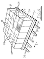
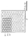
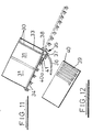
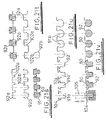
- FIGS 13 and 14 there is shown a further alternative packing configuration in which rivets 50 are housed in a plurality of rigid or semi-rigid tubes 51 of predetermined length.
- the tubes 51 are arranged in a spaced parallel relationship and are interconnected by a flexible web or membrane 52 so as to form a continuous length of flexible packaging 53.
- the tubes 51 are filled off-line and have internal profiles designed to retain the rivets in the orientation in which they are loaded.
- the tubes may have a circular cross-section 54 in which rivets 50 are arranged substantially coaxially or a T-shaped cross-section 55 in which rivets 50 are housed side-by-side such that their longitudinal axes are in parallel.
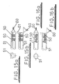
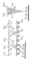
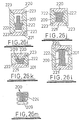
- a single web of semi-rigid (but flexible) plastics 92 is configured to provide open channel 91 for receipt of a round tube 90.
- Figures 21n and 21o show an alternative packaging embodiment in which the upper and lower membranes 92a, 92b are connected by interlocking elements rather than by heat sealing, welding or gluing.
- the upper membrane 92a defines a plurality of closure portions 97 that each overlies a respective channel 91 defined in the lower membrane 92b.
- the closure portion 97 has a profile that defines a pair of resilient depending annular lips 98 designed to engage with a pair of recesses 99 provided at the upper end of each channel 91 of the lower membrane 92b wall, and upstanding annular projections 100 that are designed to engage with ridges 101 defined at the base of the lower membrane channel 91. This enables a plurality of packages to be vertically stacked as shown in figure 21n.
- the packaging designs described above eliminate the need for an open hopper or reservoir of rivets and as they effectively provide a sealed system operators are prevented from introducing unidentifiable rivets into the fastening machine.
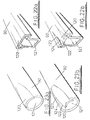
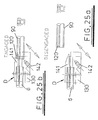
- the delivery tube 200 shown in figure 26b is of the same configuration as that of figure 26a with the exception that the wear strips 203, 204 are provided by a wire or chord insert. These may be snap-fitted, bonded or co-extruded in complementary grooves 106 in the internal wall of the delivery tube 200.
- This configuration has the advantage that the wear strips 203, 204 are replaceable (unless co-extruded) and can be made from a material different to that of the rest of the tube. If the wear strip is manufactured from an electrically conductive material it can be used to detect the position of a rivet (which is also electrically conductive) along the tube by inductive sensing thereby enabling the location of a blockage to be identified rapidly.
- the wear strip could alternatively be made in composite form (not shown) with a central core of electrically conductive material (e.g. copper) and an outer sleeve of wear-resistant material such as kevlar.
- Propulsion of the rivets along the delivery tube is by pressurised fluid such as compressed air or by linear magnetic acceleration.
- Booster points can be provided along the length of the tube to ensure that sufficient compressed air or magnetic acceleration is provided along the full length of the tube for efficient operation.
- the delivery tube may be encased in an outer protective sleeve that is filled with a supportive material such as foam or the like.
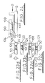
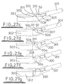
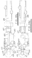
- FIGS 27a to 27i illustrate an adapter tube 300 for interconnecting a round cross-section delivery tube 301 and a T-shaped cross-section delivery tube 302.
- the adapter tube 300 would typically be disposed in the vicinity of the nose 8 of the rivet setter tool 1 and is designed to rotate rivets 50 from a roughly co-axial orientation in a main delivery tube 6, 301 of round cross-section through 90 degrees so that they can enter a short length of delivery tube 302 (or a dedicated magazine) of T-shaped cross-section at or near the nose 8.
- the above described adapter tube 300 is compact, in-line, tolerant of wear and has increased reliability in view of the lack of moving parts. In addition, it relies on air propulsion and not rivet momentum for the change in orientation, it can accommodate single or multiple rivets and can re-commence operation in the event of a temporary interruption in the air flow.
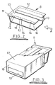
- FIG. 1 An alternative adapter tube design 350 is shown in figures 28a to 28b in which there are inlet delivery tubes 351, 352 of both round and T-shaped cross-sections and an outlet delivery tube 353 of T-shaped cross-section.
- This adapter tube 350 permits all rivet sizes to be fed into a single T-shaped outlet delivery tube or magazine 353 for delivery to the nose 8 of the rivet setter 1; relatively long rivets being fed via the round inlet delivery tube 351 and others being fed via the T-shaped inlet delivery tube 352.
- FIGS 31a to 31h illustrate a delivery tube to buffer magazine docking station in which such a problem is avoided.
- the male housing 380 carries a pair of longitudinally slidable plates 385 that are biased by a butterfly spring 386 so as to restrict the passage of the rivets 50 out of the delivery tube 6 as shown in figure 31a.
- the female housing 383 has a pair of laterally slidable jaws 387 that are biased together to close the inlet to the buffer magazine 384.
- the respective ends of the buffer magazine 384 and delivery tube 6 may float slightly in all axes to assist alignment.
- the tapered end 382 of the male housing 380 is presented to the female housing 383 of the magazine 384, with the plates 385 holding the stem 50a of a rivet 50, and is pressed into register with the female housing 383 so that the plates 385 bear against the jaws 387 (figure 31c and 31d) forcing them to part laterally.
- the delivery tube 6 retracts to allow the jaws 387 of the female housing 383 to close.
- the slidable plates 385 move to the closed position shown in figure 31a to collect the stem 50a of the next rivet 50. If there is a rivet 50 present at the male housing 380 the retraction of slidable plates 385 ensures that it is forced back into the delivery tube 6.
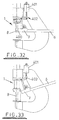
- a transfer station 7 delivers rivets directly to a side port 400 of the nose 8 of the setting tool 1 from a delivery tube 6 as is well known.
- the inventive feature of this design is that the transfer station 7 is pivotable by an actuator 401 between the two positions shown respectively in figures 32 and 33.
- the actuator 401 shown is a hydraulic or pneumatic cylinder (but could be any suitable form of actuator) connected to the transfer station 7 by a system of linkages 402.
- rivet passages (hidden) through the delivery tube 6 and transfer station 7 are in register with the side port 400 in the nose 8 so that a rivet can be loaded.
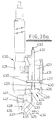
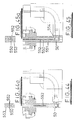
- An upper of said plates 427 has stop collars 430 in which an upper end of each rod 426 is received and a lower of said support plates 428 is connected to one end of a pneumatic or hydraulic cylinder 431 that is operable to effect sliding movement of the support frame assembly.
- the plates 427, 428 carry a delivery tube or buffer magazine 432 that extends parallel to and between the rods 426. Service cables or ducts 433 may also be routed through the plates 427, 428 alongside the delivery tube 432.
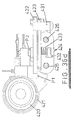
- the transfer station 425 is disposed below the lower plate 428 and carries a pusher assembly 434 (described in detail below).
- the roller 440 When the nose 436 ascends after completion of the rivet insertion operation the roller 440 re-engages with the surface of the transfer station housing and eventually with the hook 439. At this point a rivet load sensor (not shown) detects the re-engagement and may then send a control signal to initiate loading of the next rivet from the transfer station (fig 36b).
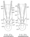
- rivets 50 are propelled from the delivery tube or buffer magazine 462 until they reach the spring gate 464 which in its rest position prevents escape of the rivets 50 from the housing 460.
- the pushers 465 are fully retracted (fig 37b).
- the propelling air supply may be turned off if necessary and the pushers 465 are then advanced partially to the position shown in figure 37c in which their ends engage the stem 50a of the leading rivet 50 so as to move it into abutment with the spring gate 464.
- the pushers 465 are disposed at a precise angle with respect to the channel 461 so that they are able to pass the stem of the rivet second in line but engage with the leading rivet.
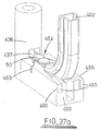
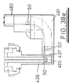
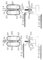
- a vertical rivet delivery tube 480 enters the transfer station housing 481 from above and to one side. Inside the housing 481 it bends through 90° into a horizontal plane and merges with a continuation channel 482 in the station.
- the channel 482 has a double bend 483 of reverse S-shape in the horizontal plane and terminates at the transfer station outlet 484 that communicates with the rivet delivery passage 485 in the nose 436 via a side port 437 in the nose.
- a pusher 486 is disposed with its longitudinal axis aligned with the outlet 484.
- the pusher 486 is reciprocal in the housing 481 in a longitudinal direction when acted upon by a probe spring 487 that is in turn acted upon by a pneumatic cylinder 488. It will be appreciated that any other appropriate actuator may be used.
- the pusher In operation, the pusher is biased by the probe spring 487 to an at-rest position, as shown in figure 38a, where it partially occupies the channel 482.
- the cylinder 488 retracts the pusher 486 against the bias of the probe spring 487 until the pusher 486 is clear of the channel 482 so as to allow rivets 50 to proceed to the gate under the propulsion of compressed air or the like (fig. 38b).
- the leading rivet is prevented from exiting through the outlet 484 of the transfer station by the presence of the gate 490.
- the pusher 486 When the rivet sensor 493 detects the presence of the leading rivet 50 the pusher 486 is released by the cylinder 498 so that the probe spring 487 pushes it against the stem 50a of the leading rivet 50 thereby trapping the rivet at the gate 486 (fig 38c). Upon receipt of the appropriate control signal the pusher 486 is then extended by the cylinder 488 to push the rivet 50 through the outlet 484 and into the nose 436 via the side port 437 (fig 38d).
- the transfer station described above allows rivets to be fed to an intermediate position outside of the nose. Since the end of the delivery tube is offset from the nose debris from the delivery tube can be removed by injection of a blast of air in a direction such that the debris not directed into the nose but egresses from a clearance port in the transfer station.
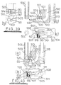
- FIGS. 39 to 54 show several alternative embodiments of the internal configuration of transfer stations used in such applications in which the transfer station is moved between a first position in which it docks under the nose or punch to load a rivet and a second position in which the transfer station is clear of the nose or punch to allow the riveting operation to be effected.
- the cover 505 carries a rivet separator finger 515 that is slidably mounted between the cover 505 and the base 503, an upstanding pin 516 on the finger 515 engaging in a diagonal slot 517 of the cover 505.
- the entire transfer station 501 is moved on a spring-loaded vertical shaft 518 disposed at the rear.
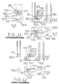
- Figures 43 to 45 show a modified embodiment of rivet setter of figures 39 to 42 in which the punch 550 has an axial bore 552 to which a source of suction pressure or vacuum is applied.
- a clamping member 553 for around the punch 550.
- the clamping member 553 applies a clamping force to the workpiece prior to insertion of the rivet into the workpiece as is described in our European Patent No. 0675774.
- the pre-clamping member 553 comprises two diametrically opposed portions flanking the punch 550 whereas in the embodiment of figure 44 the pre-clamping member 553 fully encloses the circumference of the punch 550 and a side port 554 in the nose 551 is provided for the incoming rivet 50.
- Figures 46 to 52 show an alternative embodiment of a transfer station that is used to feed rivets to the end of the rivet setter nose (i.e. into the end of the nose from which it is discharged during the riveting operation).
- the figures show the chronological sequence for loading of the rivet.
- a torsion spring 659 is supported around pin 655 and serves to bias the lever 654 in a clockwise direction against a rigid rivet feeder tube 660 that releasably connects co-axially to the end of a rivet delivery tube or magazine (shown only in figure 46) and is secured to the lever 654.
- the free end of the feeder tube 660 bends towards the nose 653 of the rivet setter 651.
- a delivery arm 661 is pivotally connected to a rearwardly extending lug 662 of the feeder tube 660 and extends parallel to the end portion thereof, towards the nose, in a slot on the underside of the feeder tube 660.
- the free end of the delivery arm 661 has a small upstanding projection 663 that is designed, in use, to engage with a rivet 664.
- the opposite end of the delivery arm 661 is connected to the lever 654 by connecting rod 665.
- rivets are fed under compressed air down the delivery tube and into the feeder tube 660 of the transfer station 651 whereupon they are transferred singly into the end of a rivet delivery passage 666 in the nose 653 as will be described below.
- the nose of the setting tool 650 is indexed towards the workpiece (figure 47) and a punch 667 in the delivery passage 666 extends downwardly to force the rivet 664 into the workpiece (figure 48) as is well known.
- the rivet 664 is releasably retained in the end of the rivet delivery passage 666 by any suitable retention means (e.g. vacuum, Velcro. adhesive, spring loaded balls etc.) such as those described in our UK Patent No. 2302833.
- This action pivots the feeder tube 660 towards the end of the nose 653 until the leading rivet 664 retained at the end of the feeder tube 660 is presented to the end of the delivery passage 666 in the nose 653 as shown in figure 50.
- Further extension of the piston 658 serves to pivot the delivery arm 661 upwards and to tension the torsion spring 659 (via the connecting rod 665 and lever 654) through a small angle so that it pushes the rivet 664 into the end of the delivery passage 666 where it is retained by the retention means (see figure 49).
- the gripping force of the retention means (not shown) is designed to be greater than that provided by the projection 263 in the delivery arm 661 so that transfer of the rivet 664 is smooth and unhindered.
- the upstanding projection 663 on the delivery arm 661 is supplemented with a pair of spring biased fingers 680 mounted on the feeder tube 660 as shown in figures 54 a, b, c, d.
- the fingers 680 extend along the feeder tube 660 and are biased together by compression springs 681 so that tips 682 of the fingers 680 are nearly in contact.
- the tips 682 of the fingers 680 trap an incoming rivet 664 and retain the rivet 664 in place until the upward movement of the delivery arm 661 separates the fingers 680 and directs it into the nose 653.
- the fingers 680 are chamfered (at 683) so as to receive the arm 661.
- the compression springs 681 of the fingers 680 serve to absorb the momentum of the rivet 664 without any impact damage.
- the upstanding projection 663 is mounted on a rounded support 684 that is received in a complementary recess 685 such that it is able to be tilted so as to accommodate both short and long stem rivets.
- the spring plate 686 and keeper plate 687 retain the projection 663 in place as shown in figures 54c and 54d.
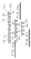
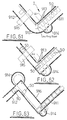
- the inlet tubes 800, 801 in the embodiment shown are approximately at right angles and meet adjacent the setter tool nose N. At the intersection of the tubes 800, 801 there is disposed a rotary gate 802 that is slotted (at 802a) to receive a single rivet. An outlet track 803 interconnects the rotary gate 802 with a delivery passage 804 in the nose N. Intermediate the two delivery tubes 800, 801, and adjacent the gate 802, is a reciprocal pusher arm 805.
- Figures 60a and 60b shows a similar escapement mechanism for a delivery tube of T-shaped cross-section.
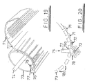
- Figure 61 illustrates an alternative in-line escapement mechanism I.
- the delivery tube 6 has a right-angled bend 910 that divides the tube into an incoming portion 911 and an outgoing portion 912. Rivets 50 are fed into the incoming portion 911 by gravity (although alternatives include air propulsion or a linear feed) and gather at the bend 910 where they are prevented from further travel. At this point the leading rivet 50 is aligned with the outgoing portion but cannot travel further through lack of propulsion.
Landscapes
- Mechanical Engineering (AREA)
- Engineering & Computer Science (AREA)
- Insertion Pins And Rivets (AREA)
- Automatic Assembly (AREA)
- Making Paper Articles (AREA)
- Electrical Discharge Machining, Electrochemical Machining, And Combined Machining (AREA)
- Sewing Machines And Sewing (AREA)
- Turning (AREA)
- Portable Nailing Machines And Staplers (AREA)
- Flanged Joints, Insulating Joints, And Other Joints (AREA)
- Details Of Spanners, Wrenches, And Screw Drivers And Accessories (AREA)
- Formation And Processing Of Food Products (AREA)
- Chutes (AREA)
Applications Claiming Priority (3)
| Application Number | Priority Date | Filing Date | Title |
|---|---|---|---|
| GBGB9816796.8A GB9816796D0 (en) | 1998-08-03 | 1998-08-03 | Improvements in or relating to fastening machines |
| GB9816796 | 1998-08-03 | ||
| EP99936862A EP1102650B1 (de) | 1998-08-03 | 1999-08-03 | Maschine zum setzen von befestigungselementen |
Related Parent Applications (1)
| Application Number | Title | Priority Date | Filing Date |
|---|---|---|---|
| EP99936862A Division EP1102650B1 (de) | 1998-08-03 | 1999-08-03 | Maschine zum setzen von befestigungselementen |
Publications (3)
| Publication Number | Publication Date |
|---|---|
| EP1297918A2 true EP1297918A2 (de) | 2003-04-02 |
| EP1297918A3 EP1297918A3 (de) | 2004-08-25 |
| EP1297918B1 EP1297918B1 (de) | 2007-02-14 |
Family
ID=10836562
Family Applications (4)
| Application Number | Title | Priority Date | Filing Date |
|---|---|---|---|
| EP99936862A Expired - Lifetime EP1102650B1 (de) | 1998-08-03 | 1999-08-03 | Maschine zum setzen von befestigungselementen |
| EP02079119A Expired - Lifetime EP1297917B1 (de) | 1998-08-03 | 1999-08-03 | Maschine zum Setzen von Befestigungselementen |
| EP02079121A Withdrawn EP1297919A2 (de) | 1998-08-03 | 1999-08-03 | Maschine zum Setzen von Befestigungslementen |
| EP02079120A Expired - Lifetime EP1297918B1 (de) | 1998-08-03 | 1999-08-03 | Maschine zum Setzen von Befestigungselementen |
Family Applications Before (3)
| Application Number | Title | Priority Date | Filing Date |
|---|---|---|---|
| EP99936862A Expired - Lifetime EP1102650B1 (de) | 1998-08-03 | 1999-08-03 | Maschine zum setzen von befestigungselementen |
| EP02079119A Expired - Lifetime EP1297917B1 (de) | 1998-08-03 | 1999-08-03 | Maschine zum Setzen von Befestigungselementen |
| EP02079121A Withdrawn EP1297919A2 (de) | 1998-08-03 | 1999-08-03 | Maschine zum Setzen von Befestigungslementen |
Country Status (13)
| Country | Link |
|---|---|
| US (8) | US6944944B1 (de) |
| EP (4) | EP1102650B1 (de) |
| JP (3) | JP4493850B2 (de) |
| KR (1) | KR100593371B1 (de) |
| CN (1) | CN1320065A (de) |
| AT (1) | ATE235330T1 (de) |
| AU (1) | AU5183599A (de) |
| BR (1) | BR9912731A (de) |
| CA (1) | CA2339530A1 (de) |
| DE (3) | DE69935169T2 (de) |
| GB (1) | GB9816796D0 (de) |
| MX (1) | MXPA01001380A (de) |
| WO (1) | WO2000007751A1 (de) |
Cited By (1)
| Publication number | Priority date | Publication date | Assignee | Title |
|---|---|---|---|---|
| CN105268897A (zh) * | 2014-07-09 | 2016-01-27 | 波音公司 | 用于操纵紧固件的设备和方法 |
Families Citing this family (118)
| Publication number | Priority date | Publication date | Assignee | Title |
|---|---|---|---|---|
| US6276050B1 (en) | 1998-07-20 | 2001-08-21 | Emhart Inc. | Riveting system and process for forming a riveted joint |
| US9015920B2 (en) | 1997-07-21 | 2015-04-28 | Newfrey Llc | Riveting system and process for forming a riveted joint |
| GB9816796D0 (en) * | 1998-08-03 | 1998-09-30 | Henrob Ltd | Improvements in or relating to fastening machines |
| DE20013585U1 (de) * | 2000-08-04 | 2000-12-07 | Avdel Verbindungselemente GmbH, 30851 Langenhagen | Vorrichtung zum Laden eines Nietmoduls mit Blindnietmuttern |
| US6942134B2 (en) | 2001-04-17 | 2005-09-13 | Newfrey Llc | Self-piercing rivet setting machine |
| JP2002316233A (ja) * | 2001-04-17 | 2002-10-29 | Nippon Pop Rivets & Fasteners Ltd | 自動穿孔型リベット締結機 |
| FR2842181B1 (fr) | 2002-07-12 | 2005-08-05 | F2 C2 System | Dispositif de stockage et de distribution de pieces notamment de rivets |
| US6986450B2 (en) | 2003-04-30 | 2006-01-17 | Henrob Limited | Fastener insertion apparatus |
| FR2859402B1 (fr) * | 2003-09-04 | 2006-01-13 | F2 C2 System | Procede de fabrication et produit logiciel adapte |
| FR2865670B1 (fr) * | 2004-01-30 | 2007-08-24 | Sylvain Guerin | Dispositif de stockage et d'alimentation d'elements de fixation. |
| US20060112343A1 (en) * | 2004-11-23 | 2006-05-25 | Palo Alto Research Center Incorporated | Methods, apparatus, and program products for aligning presentation of separately recorded experiential data streams |
| DE102005006795A1 (de) * | 2005-02-14 | 2006-08-24 | Newfrey Llc, Newark | Verfahren und Vorrichtung zum Zuführen von Verbindungselementen zu einem Verarbeitungsgerät |
| US20060258272A1 (en) * | 2005-04-11 | 2006-11-16 | Milewicz Mark G | Pushpin installer |
| DE102005028055A1 (de) * | 2005-06-16 | 2006-12-28 | Brötje-Automation GmbH | Nietauswahl und -fixiervorrichtung |
| DE102005041534A1 (de) * | 2005-08-31 | 2007-03-01 | Newfrey Llc, Newark | Verfahren und Vorrichtung zum Zuführen von Verbindungselementen zu einem Verarbeitungsgerät |
| GB0518696D0 (en) * | 2005-09-14 | 2005-10-19 | Henrob Ltd | Fastener feed method and apparatus |
| TWI271832B (en) * | 2005-10-07 | 2007-01-21 | King Yuan Electronics Co Ltd | Feeding apparatus |
| US7380326B2 (en) * | 2005-11-02 | 2008-06-03 | Whitesell International Corporation | Method of attaching a self-attaching fastener to a panel |
| FR2896173B1 (fr) * | 2006-01-16 | 2009-07-03 | F2 C2 System Sa | Dispositif d'alimentation en elements de fixation de type rivets notamment pour machine de rivetage |
| US7226308B1 (en) * | 2006-05-26 | 2007-06-05 | Centerpin Technology, Inc. | Compression snap electrical connector |
| US20080233791A1 (en) * | 2006-05-26 | 2008-09-25 | Centerpin Technology, Inc. | Compression snap electrical connector |
| US20090215306A1 (en) * | 2006-05-26 | 2009-08-27 | Centerpin Technology, Inc. | Electrical connector with compression gores |
| US7520772B2 (en) * | 2006-05-26 | 2009-04-21 | Centerpin Technology, Inc. | Compression snap electrical connector |
| US7849573B2 (en) * | 2006-09-08 | 2010-12-14 | Ford Motor Company | Apparatus for self-piercing rivet |
| US7617921B2 (en) * | 2007-02-22 | 2009-11-17 | Workman Harry W | Can manipulating system |
| US8267388B2 (en) * | 2007-09-12 | 2012-09-18 | Xradia, Inc. | Alignment assembly |
| KR101308510B1 (ko) * | 2007-11-05 | 2013-09-12 | 동부대우전자 주식회사 | 히터 내장형 흡기관을 구비하는 건조기 |
| GB0818401D0 (en) | 2008-10-08 | 2008-11-12 | Henrob Ltd | Fastener feed method and apparatus |
| DE102008051489B4 (de) | 2008-10-13 | 2021-07-01 | Böllhoff Verbindungstechnik GmbH | Setzgerät mit einem Magazin und einem Bereitstellungsmodul für Fügeelemente |
| KR101792291B1 (ko) * | 2009-11-11 | 2017-10-31 | 헨롭 리미티드 | 패스너 공급 장치 |
| JP5597435B2 (ja) * | 2010-04-22 | 2014-10-01 | 株式会社エフ・シー・シー | リベットセット装置 |
| JP5468453B2 (ja) * | 2010-04-22 | 2014-04-09 | 株式会社エフ・シー・シー | リベットセット装置 |
| CN101829758B (zh) * | 2010-05-07 | 2012-06-13 | 好孩子儿童用品有限公司 | 铆钉机 |
| DE102010047032A1 (de) * | 2010-09-30 | 2012-04-05 | Benteler Automobiltechnik Gmbh | Verfahren zum Verbinden zweier metallischer Elemente und Verbindungswerkzeug |
| NO333028B1 (no) * | 2010-11-08 | 2013-02-18 | Alustar As | Fremgangsmate for a lase en baerekrans til en stillassoyle. |
| DE102010053221A1 (de) * | 2010-12-03 | 2012-06-06 | Brötje-Automation GmbH | Nietbereitstellungseinrichtung |
| DE102010053220A1 (de) * | 2010-12-03 | 2012-06-06 | Brötje-Automation GmbH | Nietbereitstellungseinrichtung |
| DE102011103332A1 (de) | 2011-05-27 | 2012-11-29 | Newfrey Llc | Verfahren und Vorrichtung zum Zuführen von Fügeelementen |
| US8769788B2 (en) | 2011-06-17 | 2014-07-08 | Btm Corporation | Rivet machine |
| US8769789B2 (en) | 2011-06-17 | 2014-07-08 | Btm Corporation | Die for rivet machine |
| US8869365B2 (en) | 2011-06-24 | 2014-10-28 | Btm Corporation | Rivet guide head |
| SG11201400323VA (en) * | 2011-09-02 | 2014-08-28 | Pem Man Inc | Tack pin installation press |
| CN102744350A (zh) * | 2012-06-29 | 2012-10-24 | 昆山长运电子工业有限公司 | 笔记本盖铆钉自动压接机的铆钉定位装置 |
| KR101304451B1 (ko) | 2012-07-25 | 2013-09-05 | (주)한앤하이 | 가분수형 나사용 나사체결기 |
| US9027220B2 (en) | 2012-08-07 | 2015-05-12 | Newfrey Llc | Rivet setting machine |
| CN102764846A (zh) * | 2012-08-23 | 2012-11-07 | 杭州彼特环保包装有限公司 | 一种铆钉出料导轨的分离装置 |
| JP6091162B2 (ja) * | 2012-11-01 | 2017-03-08 | 三菱重工業株式会社 | 複合部材の締結制御システム、及び複合部材の締結制御方法 |
| CN102962363A (zh) * | 2012-11-06 | 2013-03-13 | 珠海锐翔电子有限公司 | 一种铜扣自动加工机 |
| US9120140B2 (en) | 2013-01-18 | 2015-09-01 | Ford Motor Company | Method and apparatus for clearing a rivet from a riveting tool |
| US9299209B2 (en) * | 2013-03-14 | 2016-03-29 | Honda Motor Co., Ltd. | Super high speed bolt delivery system |
| US8875388B1 (en) * | 2013-03-15 | 2014-11-04 | Hvac Inventors/Systemation, Inc. | Apparatus and method for placement of angle plates in transverse duct flanges |
| US9545695B2 (en) * | 2013-03-15 | 2017-01-17 | Hvac Inventors/Systemation, Inc. | Apparatus and method for placement of angle plates in transverse duct flanges |
| CN103537608B (zh) * | 2013-10-15 | 2015-07-01 | 南京航空航天大学 | 多种类铆钉自动输送装置 |
| CN103707033B (zh) * | 2013-12-23 | 2016-05-04 | 苏州博众精工科技有限公司 | 一种自动选择零件的零件安装机 |
| CN103692199A (zh) * | 2013-12-25 | 2014-04-02 | 苏州博众精工科技有限公司 | 一种锁螺丝机构 |
| US9616532B2 (en) * | 2014-04-25 | 2017-04-11 | Honda Motor Co., Ltd. | Method and apparatus for performing a search and feel assembly function |
| CN104014707A (zh) * | 2014-05-13 | 2014-09-03 | 苏州欧誉自动化科技有限公司 | 一种自冲铆接异步柔性化系统的工艺方法 |
| US9839956B2 (en) * | 2014-05-20 | 2017-12-12 | Weaver Leather, Llc | Feed assembly for a riveting machine and a method of operation of the same |
| CN104056959B (zh) * | 2014-06-05 | 2016-07-06 | 宁波新冠联机电有限公司 | 一种铆电机支架针轴模装置 |
| DE102014119189A1 (de) | 2014-12-19 | 2016-06-23 | Newfrey Llc | Fügeelementzuführvorrichtung |
| CN104668424A (zh) * | 2015-03-05 | 2015-06-03 | 儒拉玛特自动化技术(合肥)有限公司 | 多铆钉自动装配机 |
| US10113580B2 (en) * | 2015-08-17 | 2018-10-30 | The Boeing Company | Methods and apparatuses for manipulating swaging collars |
| DE102015115483A1 (de) | 2015-09-14 | 2017-03-16 | Böllhoff Verbindungstechnik GmbH | Wechselmagazin sowie System und Verfahren zum Beladen eines Wechselmagazins und eines Setzgeräts |
| BR112017024180B1 (pt) * | 2015-09-16 | 2023-03-28 | Howmet Aerospace Inc | Aparelho de alimentação de prendedores |
| DE102016113114A1 (de) * | 2016-07-15 | 2018-01-18 | Newfrey Llc | Stanzniet-Zuführeinrichtung und Stanznietvorrichtung |
| JP6615041B2 (ja) * | 2016-04-25 | 2019-12-04 | 株式会社青山製作所 | ボルトのかしめ方法及びかしめ装置 |
| DE102016210799A1 (de) | 2016-06-16 | 2017-12-21 | Leoni Kabel Gmbh | Kupplungsvorrichtung zum Verbinden langgestreckter Hohlkörper in einem Montagesystem |
| DE102016112732A1 (de) * | 2016-07-12 | 2018-01-18 | Böllhoff Verbindungstechnik GmbH | Nicht-wegvariable Elementweiche und Zufuhrverfahren |
| WO2018057569A1 (en) * | 2016-09-23 | 2018-03-29 | Commscope Technologies Llc | Tool for installing and setting rivets |
| DE102016119850A1 (de) * | 2016-10-18 | 2018-04-19 | Böllhoff Verbindungstechnik GmbH | Setzwerkzeug und Zufuhrverfahren von unterschiedlichen Fügeelementen |
| DE102016226244A1 (de) * | 2016-12-28 | 2018-06-28 | Robert Bosch Gmbh | Verfahren zum Betreiben einer Stanznietvorrichtung, Stanznietvorrichtung und Mundstück für eine Stanznietvorrichtung |
| DE102016226246A1 (de) * | 2016-12-28 | 2018-06-28 | Robert Bosch Gmbh | Verfahren zum Betreiben einer Fügevorrichtung, Fügevorrichtung und Anordnung mit Fügevorrichtung |
| DE102017209126A1 (de) * | 2016-12-29 | 2018-07-05 | Robert Bosch Gmbh | Stanznietvorrichtung zum Setzen eines Stanzniets mit einer eine Stempelkraft unterstützenden Schwingung und Verfahren zum Stanznieten mit einer solchen Stanznietvorrichtung |
| DE102017101705A1 (de) * | 2017-01-30 | 2018-08-02 | Newfrey Llc | Fügevorrichtung, Beladestation, Zuführanordnung und Verfahren zum Beladen eines Magazins |
| DE102017102707A1 (de) * | 2017-02-10 | 2018-08-16 | Ejot Gmbh & Co. Kg | Zuführeinrichtung |
| CN107181454B (zh) * | 2017-05-26 | 2023-03-21 | 重庆科技学院 | 路径延长轨道及其太阳能板间连接轨道 |
| DE102017209118A1 (de) * | 2017-05-31 | 2018-12-06 | Robert Bosch Gmbh | Stanznietvorrichtung zum setzen eines stanzniets mit einer eine stempelkraft unterstützenden schwingung, und verfahren zum stanznieten mit einer solchen stanznietvorrichtung |
| GB2569126A (en) * | 2017-12-05 | 2019-06-12 | Atlas Copco Ias Uk Ltd | Fastener magazines, and related supply systems and methods |
| GB2569122A (en) | 2017-12-05 | 2019-06-12 | Atlas Copco Ias Uk Ltd | Fastener handling devices for fastener setting machines, and related methods |
| GB2569127A (en) * | 2017-12-05 | 2019-06-12 | Atlas Copco Ias Uk Ltd | Nose arrangements for fastener setting machines, and related methods |
| US11000926B2 (en) | 2017-12-20 | 2021-05-11 | Penn Automotive, Inc. | Fastener feed head |
| US10780489B2 (en) * | 2018-02-21 | 2020-09-22 | Newfrey Llc | Tool-free opening tape feed receiver for a self-piercing rivet machine |
| DE102018205246A1 (de) | 2018-04-09 | 2019-10-10 | Robert Bosch Gmbh | Setzeinheit für eine Stanznietvorrichtung und Stanznietvorrichtung |
| US10520933B2 (en) * | 2018-04-13 | 2019-12-31 | The Boeing Company | System and method for removing a workpiece from a manufacturing fixture |
| DE102018205621A1 (de) * | 2018-04-13 | 2019-10-17 | Robert Bosch Gmbh | Stanznietvorrichtung mit Zuführeinheit für Niete |
| DE102018210362B4 (de) | 2018-06-26 | 2024-10-02 | Bayerische Motoren Werke Aktiengesellschaft | Setzwerkzeug zum Setzen wenigstens eines Formkörpers auf ein Werkstück und Verfahren |
| DE102018210474A1 (de) * | 2018-06-27 | 2020-01-02 | Audi Ag | Kompaktvereinzeler |
| US10654093B2 (en) * | 2018-07-10 | 2020-05-19 | Electroimpact, Inc. | Riveting apparatus with moveable nose portion to match an adjoining rivet feed track |
| US10643410B2 (en) | 2018-07-31 | 2020-05-05 | Newfrey Llc | Bulk rivet container and transfer cabinet |
| GB201812686D0 (en) | 2018-08-03 | 2018-09-19 | Henrob Ltd | Method of forming a riveted joint |
| CN108705022B (zh) * | 2018-08-31 | 2019-10-08 | 哈尔滨工业大学 | 一种多规格可选铆钉自动插钉装置 |
| DE102018123215A1 (de) * | 2018-09-20 | 2020-03-26 | Böllhoff Verbindungstechnik GmbH | Verbindungsmodul mit Fügevorrichtung und Elementzufuhrsystem |
| US10898943B2 (en) | 2018-09-25 | 2021-01-26 | Ford Global Technologies, Llc | Self-piercing rivet device and method of operating a self-piercing rivet device to inhibit incorrect die usage |
| US11214967B1 (en) | 2018-11-08 | 2022-01-04 | Scepaniak IP Holdings, LLC | Roof rock spreader |
| US11471932B2 (en) * | 2018-12-13 | 2022-10-18 | Howmet Aerospace Inc. | Rivet dispensing systems and methods of use thereof |
| US10987766B2 (en) * | 2019-06-25 | 2021-04-27 | Newfrey Llc | Automated electromagnetic fastener delivery system |
| CN110466944B (zh) * | 2019-09-11 | 2024-07-02 | 辽宁科技大学 | 吊挂式带式输送机 |
| CN110561072B (zh) * | 2019-09-18 | 2020-08-04 | 卢丽花 | 一种工位分料设备的使用方法 |
| DE102019125999A1 (de) * | 2019-09-26 | 2021-04-01 | Audi Ag | System zum Bereitstellen von Klammern |
| WO2021079589A1 (ja) * | 2019-10-21 | 2021-04-29 | 株式会社アルバック | 成膜装置 |
| US12291875B1 (en) | 2019-12-11 | 2025-05-06 | Scepaniak IP Holdings, LLC | Commercial roofing screw machine |
| US10807806B1 (en) | 2020-03-12 | 2020-10-20 | Sentry Equipment Erectors, Inc. | Linear shuttle for container invertors in a conveyor system |
| EP4219042B1 (de) | 2020-05-06 | 2025-03-26 | Newfrey LLC | Befestigungsvorrichtung mit zwei magazinen zum zuführen von befestigungelementen |
| CN111660277B (zh) * | 2020-06-28 | 2023-02-10 | 中铁九局集团电务工程有限公司 | 一种螺栓安装臂 |
| WO2022008040A1 (fr) * | 2020-07-07 | 2022-01-13 | Seti-Tec | Dispositif de transfert d'au moins un élément de fixation |
| CN112170767B (zh) * | 2020-09-18 | 2021-07-13 | 山东大学 | 一种铆钉送进装置及方法 |
| DE102021105466A1 (de) | 2021-03-08 | 2022-09-08 | Bayerische Motoren Werke Aktiengesellschaft | Fügevorrichtung und Verfahren zum Betreiben einer Fügevorrichtung |
| DE102021120006B4 (de) * | 2021-08-02 | 2024-04-18 | Raimund Beck Nageltechnik Gmbh | Zuführeinrichtung, Anordnung und Verwendung einer solchen Anordnung |
| DE102021131809A1 (de) * | 2021-12-02 | 2023-06-07 | Grammer Aktiengesellschaft | Verfahren zur Herstellung einer Verbindung für ein Ausstattungsteil eines Fahrzeuges |
| CN114985654B (zh) * | 2022-05-27 | 2023-06-13 | 武汉理工大学 | 多自由度包络成形高精度高刚度模架模具系统设计方法 |
| EP4382225A1 (de) * | 2022-12-05 | 2024-06-12 | Airbus Operations GmbH | Befestigungselement-zuführsystem |
| DE102023201098A1 (de) * | 2023-02-10 | 2024-08-14 | Arnold Umformtechnik Gmbh & Co. Kg | Vorrichtung und Verfahren zum Zuführen von Verbindungselementen und Anordnung |
| WO2024168417A1 (en) * | 2023-02-16 | 2024-08-22 | Doben Limited | Automated floating insertion tool for push-in fasteners |
| DE102023136245A1 (de) * | 2023-12-21 | 2025-06-26 | Atlas Copco Ias Gmbh | Transportvorrichtung |
| DE102024106926A1 (de) * | 2024-03-11 | 2025-09-11 | Profil Verbindungstechnik Gmbh & Co. Kg | Setzeinrichtung und Verfahren zu deren Betrieb |
| EP4699719A1 (de) | 2024-08-20 | 2026-02-25 | Böllhoff Verbindungstechnik GmbH | Zuführvorrichtung für fügeelemente, setzwerkzeug mit der zuführvorrichtung und dazugehöriges zuführverfahren |
| DE102024138157B3 (de) | 2024-12-17 | 2026-03-05 | Audi Aktiengesellschaft | Setzsystem |
| CN119825993A (zh) * | 2024-12-25 | 2025-04-15 | 红海湾实验室 | 用于海底管线铺装的导向磁场锚钉埋设机器人及使用方法 |
Family Cites Families (93)
| Publication number | Priority date | Publication date | Assignee | Title |
|---|---|---|---|---|
| US1839490A (en) | 1928-12-04 | 1932-01-05 | Western Electric Co | Apparatus for distributing parts |
| US2216403A (en) | 1938-05-30 | 1940-10-01 | Frankfurter Maschb Ag | Drilling and riveting machine |
| US2493868A (en) * | 1943-10-26 | 1950-01-10 | Curtiss Wright Corp | Air gun rivet feed |
| US2661992A (en) * | 1951-09-08 | 1953-12-08 | Larry M Harris | Gate mechanism for bottle dispensing containers |
| US3029918A (en) * | 1954-10-27 | 1962-04-17 | Anchor Hocking Glass Corp | Device for feeding closure caps |
| US3339799A (en) | 1965-09-07 | 1967-09-05 | Gregory Ind Inc | Fastener feed assembly including fastener size adjusting means |
| US3682341A (en) * | 1971-02-24 | 1972-08-08 | Langsenkamp Co F H | Container opening apparatus |
| US3789490A (en) * | 1972-02-17 | 1974-02-05 | Omark Industries Inc | Stud storage system |
| GB1431740A (en) | 1973-08-16 | 1976-04-14 | Schaeffer Homberg Gmbh | Machines for fixing together fastener components |
| US3960191A (en) | 1975-06-17 | 1976-06-01 | Illinois Tool Works Inc. | Fastener feeding and driving attachment |
| US4174802A (en) | 1976-03-24 | 1979-11-20 | Bruno Maestri | Magazine device for continuously feeding nails into a nail driving machine |
| US4044462A (en) | 1976-10-26 | 1977-08-30 | General-Electro Mechanical Corporation | Rivet blank feeder for riveting apparatus |
| US4180195A (en) | 1978-01-16 | 1979-12-25 | The Boeing Company | Rivet delivery and locating apparatus |
| DE2826418C2 (de) | 1978-06-16 | 1986-10-30 | Schaeffer-Homberg Gmbh, 5600 Wuppertal | Maschine zum Ansetzen von aus Ober- und Unterteil bestehenden Knöpfen, Nieten oder dergleichen an Kleidungsstücke |
| JPS5538564U (de) * | 1978-09-01 | 1980-03-12 | ||
| DE2856868A1 (de) | 1978-12-30 | 1980-07-17 | Schaeffer Homberg Gmbh | Vorrichtung an einer ansetzmaschine |
| JPS6018263Y2 (ja) | 1979-09-28 | 1985-06-03 | 有限会社新城製作所 | ピアスナツト自動組立機におけるシユ−トホ−ス接続装置 |
| JPS5677042A (en) * | 1979-11-26 | 1981-06-25 | Press Kogyo Kk | Method and device for caulking rivet simultaneously with its insertion |
| JPS56102437A (en) | 1980-01-11 | 1981-08-15 | Toyota Motor Corp | Parts feed magazine for automatic assembly machine |
| US4765057A (en) * | 1980-02-02 | 1988-08-23 | Multifastener Corporation | Self-attaching fastener, panel assembly and installation apparatus |
| US4555838A (en) * | 1983-03-28 | 1985-12-03 | Multifastener Corp. | Method of installing self-attaching fasteners |
| NZ197560A (en) * | 1980-07-18 | 1984-05-31 | Furma Mfg Co Pty Ltd | Mounting rivets in a flexible carrier |
| JPS603559B2 (ja) | 1981-03-17 | 1985-01-29 | 松下電器産業株式会社 | 自動ねじ締め機 |
| US4463888A (en) | 1981-04-22 | 1984-08-07 | Duo-Fast Corporation | Fastener driving tool |
| DE3301243C2 (de) | 1983-01-15 | 1985-07-04 | Mannesmann AG, 4000 Düsseldorf | Nietzuführungseinrichtung an einer Nietmaschine |
| US4497197A (en) | 1983-02-18 | 1985-02-05 | Chicago Pneumatic Tool Company | Pneumatic hydraulic hand-held power unit |
| IL71907A (en) | 1983-05-27 | 1986-11-30 | Nietek Pty Ltd | Feeders for headed fasteners and riveting machine including it |
| GB8317389D0 (en) | 1983-06-27 | 1983-07-27 | Bifurcated & Tubular Rivet Co | Rivetting machines |
| JPS6062424A (ja) | 1983-09-13 | 1985-04-10 | Nissan Motor Co Ltd | 部品打込装置への部品供給装置 |
| US4720215A (en) | 1984-10-31 | 1988-01-19 | Grumman Aerospace Corporation | Rivet delivery system |
| US4592136A (en) | 1985-02-14 | 1986-06-03 | Usm Corporation | Fastener presentation device |
| SE447552B (sv) | 1985-04-09 | 1986-11-24 | Asea Ab | Forfarande och installation for montering av muttrar i ett arbetsstycke |
| JPS6263025A (ja) | 1985-09-11 | 1987-03-19 | Matsushita Electric Ind Co Ltd | 頭付棒材供給装置 |
| JPS63110182A (ja) * | 1986-10-29 | 1988-05-14 | 株式会社村田製作所 | 電子部品チツプ収納カセツト |
| US4832555A (en) * | 1988-03-18 | 1989-05-23 | Gordon John H | Gasket holding and feeding magazine |
| FR2640245B1 (fr) | 1988-12-08 | 1992-06-12 | Garonne Ets Auriol & Cie | Procede de distribution de pieces et dispositifs de mise en oeuvre |
| US4988255A (en) * | 1989-02-22 | 1991-01-29 | The Upjohn Company | Unpackaging machine |
| GB2232110A (en) | 1989-05-26 | 1990-12-05 | Avdel Systems Ltd | Fastener installation apparatus |
| US5201892A (en) * | 1989-06-30 | 1993-04-13 | Ltv Areospace And Defense Company | Rivet orientating device |
| US4988028A (en) | 1989-12-01 | 1991-01-29 | Emhart, Inc. | Automatic riveting machine |
| FR2662622B1 (fr) | 1990-06-05 | 1994-05-13 | Haute Garonne Ets Auriol Cie Ate | Dispositif de selection et distribution de pieces telles que rivets. |
| US5123162A (en) * | 1990-12-06 | 1992-06-23 | Wing Enterprises, Inc. | Automatic rivet feed apparatus |
| US5193717A (en) * | 1991-04-30 | 1993-03-16 | Electroimpact, Inc. | Fastener feed system |
| DE4117767A1 (de) | 1991-05-31 | 1992-12-03 | Schaeffer Gmbh | Maschine zum ansetzen von knoepfen, nieten oder dergleichen, vorzugsweise an bekleidungsstuecken |
| JP2950662B2 (ja) | 1991-10-11 | 1999-09-20 | 東京マルチファスナー株式会社 | 部品連続供給装置 |
| DE4211278C1 (de) | 1992-04-03 | 1993-10-14 | Wolfgang Dipl Ing Luckhardt | Zuführvorrichtung zum Zuführen von Fügeteilen |
| DE69313711T3 (de) | 1992-04-21 | 2004-08-05 | Ariel Industries Plc | Zufuhrrohr für Befestigungselemente |
| US5360137A (en) | 1992-07-17 | 1994-11-01 | Yugenkaisha Shinjo Seisakusho | Row feeder for distributing nuts |
| DE4225415A1 (de) | 1992-07-31 | 1994-02-03 | Emhart Inc | Bolzenschweißvorrichtung |
| GB9226517D0 (en) | 1992-12-19 | 1993-02-10 | Henrob Ltd | Improvements in or relating to sefl-piercing riveting |
| DE4244403A1 (de) | 1992-12-29 | 1994-07-07 | Deutsche Aerospace Airbus | Automatische Nietmaschine |
| US5813114A (en) | 1993-01-07 | 1998-09-29 | Henrob Ltd. | Fastening tool including fastener-supporting nodes in the nose thereof |
| IT1272121B (it) * | 1993-03-22 | 1997-06-11 | Bears Srl | Sistema per la selezione e l'alimentazione automatica di rivetti preorientati per macchine rivettatrici |
| SI0690848T1 (en) | 1993-03-26 | 1998-06-30 | Pharmacia & Upjohn Company | Piperazinylpyridinyl water clathrates |
| DE4310953A1 (de) | 1993-04-02 | 1994-10-13 | Wolfgang Dipl Ing Luckhardt | Einpresseinrichtung zum Einpressen von Fügeteilen |
| DE4315403A1 (de) | 1993-05-08 | 1994-11-10 | Reich Maschf Gmbh Karl | Schraubgerät mit einer Fördervorrichtung |
| EP0725702A1 (de) | 1993-10-28 | 1996-08-14 | Maschinenbau Dieter Schmidt | Vorrichtung zur verwendung in einer presse zum zuführen von verbindungselementen und deren befestigung in werkstücken durch verpressen |
| JPH07132424A (ja) | 1993-11-09 | 1995-05-23 | Yoshitaka Aoyama | 移動台における部品供給装置 |
| DE4401981A1 (de) * | 1994-01-25 | 1995-07-27 | Stocko Metallwarenfab Henkels | Sortiermagazin |
| AUPM507094A0 (en) | 1994-04-14 | 1994-05-05 | Henrob Ltd | Improved fastening machine |
| US5476204A (en) | 1994-06-09 | 1995-12-19 | National Die & Button Mould Co., Ltd. | Automated stud setting apparatus |
| DE4447620C2 (de) | 1994-06-10 | 2003-01-23 | Profil Verbindungstechnik Gmbh | Haltefinger und Setzkopf mit mehreren solchen Haltefingern |
| FR2720963B1 (fr) | 1994-06-13 | 1996-09-06 | Haute Garonne Ateliers | Dispositif de distribution de pièces à l'unité et dispositif de stockage de ces pièces. |
| DE4423165C2 (de) | 1994-07-04 | 1996-06-20 | Michael Feldpausch | Vorrichtung zum Bereitstellen von Befestigungselementen |
| DE4433850A1 (de) * | 1994-09-22 | 1996-03-28 | Chilinov Sarl | Verfahren und Vorrichtung zum Entleeren eines Behälters |
| IT1278986B1 (it) | 1995-03-10 | 1997-12-02 | Crea Srl | Macchina e procedimento per il piantaggio di inserti in pezzi di lamiera |
| GB9505271D0 (en) | 1995-03-16 | 1995-05-03 | Ariel Ind Plc | Pivoted-nose fastener application machine |
| US5579975A (en) | 1995-04-19 | 1996-12-03 | Senco Products, Inc. | Fastener driving tool for locating a pre-existing through hole in a workpiece and driving a fastener therethrough |
| DE29507041U1 (de) * | 1995-04-26 | 1995-08-03 | Emhart Inc., Newark, Del. | Zuführleitung mit einer Führungsbahn |
| US5779609A (en) | 1996-01-16 | 1998-07-14 | Applied Robotics, Inc. | Integrated stud welding robotic tool changing system |
| US5772098A (en) | 1996-03-29 | 1998-06-30 | Senco Products, Inc. | Feed assembly for a fastener driving tool |
| AU2893897A (en) | 1996-05-07 | 1997-11-26 | Schaeffer Gmbh | Magazine, in particular replaceable magazine on a setting machine for rivets, snap fasteners etc. |
| AUPO045296A0 (en) | 1996-06-14 | 1996-07-11 | Henrob Ltd | Feeding heads for fastening machines |
| US5794831A (en) | 1996-07-12 | 1998-08-18 | Illinois Tool Works Inc. | Fastener detection and firing control system for powered fastener driving tools |
| DE19628170A1 (de) | 1996-07-12 | 1998-01-15 | Hilti Ag | Gerät zum Eintreiben von Befestigungselementen in harte Untergründe |
| DE19644541C2 (de) | 1996-10-26 | 2003-05-28 | Audi Ag | Vorrichtung zum Zuführen von Befestigungselementen |
| US5870886A (en) * | 1997-02-03 | 1999-02-16 | The West Company, Incorporated | Transfer system for transferring objects into a barrier isolator |
| EP0882546B1 (de) | 1997-06-07 | 2003-09-03 | Maschinenbau Dieter Schmidt | Versorgungssystem zum Zuführen von Verbindungselementen von einer Versorgungseinheit an einen Stanzkopf |
| US6276050B1 (en) | 1998-07-20 | 2001-08-21 | Emhart Inc. | Riveting system and process for forming a riveted joint |
| US6052882A (en) * | 1997-09-19 | 2000-04-25 | Saturn Tool Company, Llc | Insertion device for inserting spacers |
| DE29719744U1 (de) | 1997-11-06 | 1998-02-26 | Emhart Inc., Newark, Del. | Transportvorrichtung für längliche mit einem Kopf und einem Schaft ausgebildete Bauteile |
| US5988026A (en) | 1997-12-03 | 1999-11-23 | Senco Products, Inc. | Screw feed and driver for a screw driving tool |
| JP3520754B2 (ja) | 1997-12-19 | 2004-04-19 | 日立工機株式会社 | 打込機 |
| GB9816796D0 (en) * | 1998-08-03 | 1998-09-30 | Henrob Ltd | Improvements in or relating to fastening machines |
| US6347449B1 (en) | 1998-10-21 | 2002-02-19 | Emhart Inc. | Modular portable rivet setting tool |
| US6264063B1 (en) | 1998-10-23 | 2001-07-24 | Vought Aircraft Industries, Inc. | Orientation maintained fastener delivery system and method |
| US6276563B1 (en) * | 1999-10-12 | 2001-08-21 | Motorola, Inc. | Verification and lockout apparatus for bulk feeder |
| US7599790B2 (en) | 2004-03-23 | 2009-10-06 | Google Inc. | Generating and serving tiles in a digital mapping system |
| US7734412B2 (en) | 2006-11-02 | 2010-06-08 | Yahoo! Inc. | Method of client side map rendering with tiled vector data |
| US7925100B2 (en) | 2007-07-31 | 2011-04-12 | Microsoft Corporation | Tiled packaging of vector image data |
| US9064341B2 (en) | 2012-06-05 | 2015-06-23 | Apple Inc. | Method, system and apparatus for rendering a map according to hybrid map data |
| US9269178B2 (en) | 2012-06-05 | 2016-02-23 | Apple Inc. | Virtual camera for 3D maps |
| US20140009576A1 (en) | 2012-07-05 | 2014-01-09 | Alcatel-Lucent Usa Inc. | Method and apparatus for compressing, encoding and streaming graphics |
-
1998
- 1998-08-03 GB GBGB9816796.8A patent/GB9816796D0/en not_active Ceased
-
1999
- 1999-08-03 MX MXPA01001380A patent/MXPA01001380A/es unknown
- 1999-08-03 EP EP99936862A patent/EP1102650B1/de not_active Expired - Lifetime
- 1999-08-03 AU AU51835/99A patent/AU5183599A/en not_active Abandoned
- 1999-08-03 DE DE69935169T patent/DE69935169T2/de not_active Expired - Lifetime
- 1999-08-03 WO PCT/GB1999/002545 patent/WO2000007751A1/en not_active Ceased
- 1999-08-03 EP EP02079119A patent/EP1297917B1/de not_active Expired - Lifetime
- 1999-08-03 AT AT99936862T patent/ATE235330T1/de not_active IP Right Cessation
- 1999-08-03 CN CN99811588A patent/CN1320065A/zh active Pending
- 1999-08-03 KR KR1020017001481A patent/KR100593371B1/ko not_active Expired - Lifetime
- 1999-08-03 CA CA002339530A patent/CA2339530A1/en not_active Abandoned
- 1999-08-03 JP JP2000563419A patent/JP4493850B2/ja not_active Expired - Lifetime
- 1999-08-03 BR BR9912731-8A patent/BR9912731A/pt not_active Application Discontinuation
- 1999-08-03 DE DE69935170T patent/DE69935170T2/de not_active Expired - Lifetime
- 1999-08-03 DE DE69906308T patent/DE69906308T2/de not_active Expired - Lifetime
- 1999-08-03 EP EP02079121A patent/EP1297919A2/de not_active Withdrawn
- 1999-08-03 US US09/762,200 patent/US6944944B1/en not_active Expired - Lifetime
- 1999-08-03 EP EP02079120A patent/EP1297918B1/de not_active Expired - Lifetime
-
2001
- 2001-02-05 US US09/762,247 patent/US6692213B1/en not_active Expired - Lifetime
-
2005
- 2005-04-08 US US11/102,335 patent/US7487583B2/en not_active Expired - Fee Related
-
2006
- 2006-07-21 JP JP2006199284A patent/JP4494372B2/ja not_active Expired - Fee Related
- 2006-07-21 JP JP2006199263A patent/JP4417933B2/ja not_active Expired - Fee Related
-
2009
- 2009-01-20 US US12/356,225 patent/US7849579B2/en not_active Expired - Fee Related
-
2010
- 2010-11-08 US US12/941,539 patent/US8850685B2/en not_active Expired - Fee Related
-
2014
- 2014-09-05 US US14/478,764 patent/US9352383B2/en not_active Expired - Fee Related
-
2016
- 2016-04-28 US US15/141,547 patent/US9776239B2/en not_active Expired - Fee Related
-
2017
- 2017-08-25 US US15/687,087 patent/US10099273B2/en not_active Expired - Fee Related
Cited By (2)
| Publication number | Priority date | Publication date | Assignee | Title |
|---|---|---|---|---|
| CN105268897A (zh) * | 2014-07-09 | 2016-01-27 | 波音公司 | 用于操纵紧固件的设备和方法 |
| CN105268897B (zh) * | 2014-07-09 | 2018-07-31 | 波音公司 | 用于操纵紧固件的设备 |
Also Published As
Similar Documents
| Publication | Publication Date | Title |
|---|---|---|
| EP1297918B1 (de) | Maschine zum Setzen von Befestigungselementen | |
| US6796454B1 (en) | Fastening machines | |
| EP2340135B1 (de) | Nietvorrichtung und verfahren | |
| EP1945391B1 (de) | Verfahren und vorrichtung zur zuführung von befestigungselementen | |
| EP0409068B1 (de) | Vorrichtung zur Herstellung eines Reissverschlusses | |
| US20090010750A1 (en) | Method of handling clamshell containers containing a particulate aliquot | |
| EP0302362B1 (de) | Vorrichtung zum Anbringen von Bestandteilen eines Reissverschlusses | |
| US5306115A (en) | Reciprocating member for dispensing flat articles | |
| EP3609635B1 (de) | Clip zum verbinden von nietbändern |
Legal Events
| Date | Code | Title | Description |
|---|---|---|---|
| PUAI | Public reference made under article 153(3) epc to a published international application that has entered the european phase |
Free format text: ORIGINAL CODE: 0009012 |
|
| AC | Divisional application: reference to earlier application |
Ref document number: 1102650 Country of ref document: EP Kind code of ref document: P |
|
| AK | Designated contracting states |
Kind code of ref document: A2 Designated state(s): AT BE CH CY DE DK ES FI FR GB GR IE IT LI LU MC NL PT SE |
|
| PUAL | Search report despatched |
Free format text: ORIGINAL CODE: 0009013 |
|
| AK | Designated contracting states |
Kind code of ref document: A3 Designated state(s): AT BE CH CY DE DK ES FI FR GB GR IE IT LI LU MC NL PT SE |
|
| 17P | Request for examination filed |
Effective date: 20050224 |
|
| AKX | Designation fees paid |
Designated state(s): DE FR GB |
|
| RAP1 | Party data changed (applicant data changed or rights of an application transferred) |
Owner name: HENROB LIMITED |
|
| GRAP | Despatch of communication of intention to grant a patent |
Free format text: ORIGINAL CODE: EPIDOSNIGR1 |
|
| GRAS | Grant fee paid |
Free format text: ORIGINAL CODE: EPIDOSNIGR3 |
|
| GRAA | (expected) grant |
Free format text: ORIGINAL CODE: 0009210 |
|
| AC | Divisional application: reference to earlier application |
Ref document number: 1102650 Country of ref document: EP Kind code of ref document: P |
|
| AK | Designated contracting states |
Kind code of ref document: B1 Designated state(s): DE FR GB |
|
| REG | Reference to a national code |
Ref country code: GB Ref legal event code: FG4D |
|
| REF | Corresponds to: |
Ref document number: 69935170 Country of ref document: DE Date of ref document: 20070329 Kind code of ref document: P |
|
| ET | Fr: translation filed | ||
| PLBE | No opposition filed within time limit |
Free format text: ORIGINAL CODE: 0009261 |
|
| STAA | Information on the status of an ep patent application or granted ep patent |
Free format text: STATUS: NO OPPOSITION FILED WITHIN TIME LIMIT |
|
| 26N | No opposition filed |
Effective date: 20071115 |
|
| PGFP | Annual fee paid to national office [announced via postgrant information from national office to epo] |
Ref country code: FR Payment date: 20110818 Year of fee payment: 13 Ref country code: DE Payment date: 20110803 Year of fee payment: 13 Ref country code: GB Payment date: 20110803 Year of fee payment: 13 |
|
| GBPC | Gb: european patent ceased through non-payment of renewal fee |
Effective date: 20120803 |
|
| REG | Reference to a national code |
Ref country code: FR Ref legal event code: ST Effective date: 20130430 |
|
| PG25 | Lapsed in a contracting state [announced via postgrant information from national office to epo] |
Ref country code: GB Free format text: LAPSE BECAUSE OF NON-PAYMENT OF DUE FEES Effective date: 20120803 Ref country code: DE Free format text: LAPSE BECAUSE OF NON-PAYMENT OF DUE FEES Effective date: 20130301 |
|
| PG25 | Lapsed in a contracting state [announced via postgrant information from national office to epo] |
Ref country code: FR Free format text: LAPSE BECAUSE OF NON-PAYMENT OF DUE FEES Effective date: 20120831 |
|
| REG | Reference to a national code |
Ref country code: DE Ref legal event code: R119 Ref document number: 69935170 Country of ref document: DE Effective date: 20130301 |