EP1286405A1 - Alimentation en electricite utilisant une pile a combustible et accumulateur chargeable/dechargeable - Google Patents
Alimentation en electricite utilisant une pile a combustible et accumulateur chargeable/dechargeable Download PDFInfo
- Publication number
- EP1286405A1 EP1286405A1 EP01921929A EP01921929A EP1286405A1 EP 1286405 A1 EP1286405 A1 EP 1286405A1 EP 01921929 A EP01921929 A EP 01921929A EP 01921929 A EP01921929 A EP 01921929A EP 1286405 A1 EP1286405 A1 EP 1286405A1
- Authority
- EP
- European Patent Office
- Prior art keywords
- fuel cell
- output value
- target output
- power
- power demand
- Prior art date
- Legal status (The legal status is an assumption and is not a legal conclusion. Google has not performed a legal analysis and makes no representation as to the accuracy of the status listed.)
- Granted
Links
- 239000000446 fuel Substances 0.000 title claims abstract description 310
- 230000008859 change Effects 0.000 claims abstract description 66
- 230000004043 responsiveness Effects 0.000 claims abstract description 35
- 230000001133 acceleration Effects 0.000 claims description 100
- 238000000034 method Methods 0.000 claims description 40
- 230000007423 decrease Effects 0.000 claims description 18
- 238000007599 discharging Methods 0.000 claims description 14
- 238000002485 combustion reaction Methods 0.000 claims description 4
- OKKJLVBELUTLKV-UHFFFAOYSA-N Methanol Chemical compound OC OKKJLVBELUTLKV-UHFFFAOYSA-N 0.000 description 48
- 230000008569 process Effects 0.000 description 31
- UGFAIRIUMAVXCW-UHFFFAOYSA-N Carbon monoxide Chemical compound [O+]#[C-] UGFAIRIUMAVXCW-UHFFFAOYSA-N 0.000 description 15
- 229910002091 carbon monoxide Inorganic materials 0.000 description 15
- 238000010586 diagram Methods 0.000 description 15
- 239000006200 vaporizer Substances 0.000 description 14
- 230000006735 deficit Effects 0.000 description 13
- XLYOFNOQVPJJNP-UHFFFAOYSA-N water Chemical compound O XLYOFNOQVPJJNP-UHFFFAOYSA-N 0.000 description 13
- 230000005540 biological transmission Effects 0.000 description 12
- 239000002737 fuel gas Substances 0.000 description 10
- 239000000567 combustion gas Substances 0.000 description 8
- 230000007246 mechanism Effects 0.000 description 7
- 230000002829 reductive effect Effects 0.000 description 7
- 238000006243 chemical reaction Methods 0.000 description 5
- 230000000052 comparative effect Effects 0.000 description 5
- 239000007789 gas Substances 0.000 description 5
- UFHFLCQGNIYNRP-UHFFFAOYSA-N Hydrogen Chemical compound [H][H] UFHFLCQGNIYNRP-UHFFFAOYSA-N 0.000 description 4
- 239000003502 gasoline Substances 0.000 description 4
- 239000001257 hydrogen Substances 0.000 description 4
- 229910052739 hydrogen Inorganic materials 0.000 description 4
- 230000004044 response Effects 0.000 description 4
- OKTJSMMVPCPJKN-UHFFFAOYSA-N Carbon Chemical compound [C] OKTJSMMVPCPJKN-UHFFFAOYSA-N 0.000 description 3
- QVGXLLKOCUKJST-UHFFFAOYSA-N atomic oxygen Chemical compound [O] QVGXLLKOCUKJST-UHFFFAOYSA-N 0.000 description 3
- 229910052799 carbon Inorganic materials 0.000 description 3
- 230000003247 decreasing effect Effects 0.000 description 3
- 238000003487 electrochemical reaction Methods 0.000 description 3
- 230000006870 function Effects 0.000 description 3
- VNWKTOKETHGBQD-UHFFFAOYSA-N methane Chemical compound C VNWKTOKETHGBQD-UHFFFAOYSA-N 0.000 description 3
- 239000001301 oxygen Substances 0.000 description 3
- 229910052760 oxygen Inorganic materials 0.000 description 3
- 239000005518 polymer electrolyte Substances 0.000 description 3
- 238000006057 reforming reaction Methods 0.000 description 3
- 239000007787 solid Substances 0.000 description 3
- 230000000153 supplemental effect Effects 0.000 description 3
- CURLTUGMZLYLDI-UHFFFAOYSA-N Carbon dioxide Chemical compound O=C=O CURLTUGMZLYLDI-UHFFFAOYSA-N 0.000 description 2
- 230000008901 benefit Effects 0.000 description 2
- 239000003990 capacitor Substances 0.000 description 2
- 230000003111 delayed effect Effects 0.000 description 2
- 230000000994 depressogenic effect Effects 0.000 description 2
- 239000003792 electrolyte Substances 0.000 description 2
- 238000002347 injection Methods 0.000 description 2
- 239000007924 injection Substances 0.000 description 2
- 230000003993 interaction Effects 0.000 description 2
- 230000005415 magnetization Effects 0.000 description 2
- 239000012528 membrane Substances 0.000 description 2
- 239000007800 oxidant agent Substances 0.000 description 2
- 230000001590 oxidative effect Effects 0.000 description 2
- 230000036647 reaction Effects 0.000 description 2
- 238000005070 sampling Methods 0.000 description 2
- 239000002912 waste gas Substances 0.000 description 2
- 229920000049 Carbon (fiber) Polymers 0.000 description 1
- 230000009471 action Effects 0.000 description 1
- 230000002411 adverse Effects 0.000 description 1
- 238000004378 air conditioning Methods 0.000 description 1
- 229910002092 carbon dioxide Inorganic materials 0.000 description 1
- 239000001569 carbon dioxide Substances 0.000 description 1
- 239000004917 carbon fiber Substances 0.000 description 1
- 239000003054 catalyst Substances 0.000 description 1
- 238000004140 cleaning Methods 0.000 description 1
- 239000004020 conductor Substances 0.000 description 1
- 230000000694 effects Effects 0.000 description 1
- 230000005611 electricity Effects 0.000 description 1
- 238000005516 engineering process Methods 0.000 description 1
- 239000004744 fabric Substances 0.000 description 1
- 239000012530 fluid Substances 0.000 description 1
- 230000004907 flux Effects 0.000 description 1
- 238000005286 illumination Methods 0.000 description 1
- 239000003014 ion exchange membrane Substances 0.000 description 1
- 230000000670 limiting effect Effects 0.000 description 1
- 230000007257 malfunction Effects 0.000 description 1
- 239000000463 material Substances 0.000 description 1
- 239000000203 mixture Substances 0.000 description 1
- 239000003345 natural gas Substances 0.000 description 1
- 230000002093 peripheral effect Effects 0.000 description 1
- 230000000750 progressive effect Effects 0.000 description 1
- 238000005086 pumping Methods 0.000 description 1
- 230000009467 reduction Effects 0.000 description 1
- 238000002407 reforming Methods 0.000 description 1
- 230000002441 reversible effect Effects 0.000 description 1
- 239000013589 supplement Substances 0.000 description 1
- 230000001360 synchronised effect Effects 0.000 description 1
- 238000011144 upstream manufacturing Methods 0.000 description 1
Images


Classifications
-
- B—PERFORMING OPERATIONS; TRANSPORTING
- B60—VEHICLES IN GENERAL
- B60W—CONJOINT CONTROL OF VEHICLE SUB-UNITS OF DIFFERENT TYPE OR DIFFERENT FUNCTION; CONTROL SYSTEMS SPECIALLY ADAPTED FOR HYBRID VEHICLES; ROAD VEHICLE DRIVE CONTROL SYSTEMS FOR PURPOSES NOT RELATED TO THE CONTROL OF A PARTICULAR SUB-UNIT
- B60W20/00—Control systems specially adapted for hybrid vehicles
- B60W20/10—Controlling the power contribution of each of the prime movers to meet required power demand
- B60W20/13—Controlling the power contribution of each of the prime movers to meet required power demand in order to stay within battery power input or output limits; in order to prevent overcharging or battery depletion
-
- B—PERFORMING OPERATIONS; TRANSPORTING
- B60—VEHICLES IN GENERAL
- B60L—PROPULSION OF ELECTRICALLY-PROPELLED VEHICLES; SUPPLYING ELECTRIC POWER FOR AUXILIARY EQUIPMENT OF ELECTRICALLY-PROPELLED VEHICLES; ELECTRODYNAMIC BRAKE SYSTEMS FOR VEHICLES IN GENERAL; MAGNETIC SUSPENSION OR LEVITATION FOR VEHICLES; MONITORING OPERATING VARIABLES OF ELECTRICALLY-PROPELLED VEHICLES; ELECTRIC SAFETY DEVICES FOR ELECTRICALLY-PROPELLED VEHICLES
- B60L50/00—Electric propulsion with power supplied within the vehicle
- B60L50/50—Electric propulsion with power supplied within the vehicle using propulsion power supplied by batteries or fuel cells
-
- B—PERFORMING OPERATIONS; TRANSPORTING
- B60—VEHICLES IN GENERAL
- B60K—ARRANGEMENT OR MOUNTING OF PROPULSION UNITS OR OF TRANSMISSIONS IN VEHICLES; ARRANGEMENT OR MOUNTING OF PLURAL DIVERSE PRIME-MOVERS IN VEHICLES; AUXILIARY DRIVES FOR VEHICLES; INSTRUMENTATION OR DASHBOARDS FOR VEHICLES; ARRANGEMENTS IN CONNECTION WITH COOLING, AIR INTAKE, GAS EXHAUST OR FUEL SUPPLY OF PROPULSION UNITS IN VEHICLES
- B60K6/00—Arrangement or mounting of plural diverse prime-movers for mutual or common propulsion, e.g. hybrid propulsion systems comprising electric motors and internal combustion engines ; Control systems therefor, i.e. systems controlling two or more prime movers, or controlling one of these prime movers and any of the transmission, drive or drive units Informative references: mechanical gearings with secondary electric drive F16H3/72; arrangements for handling mechanical energy structurally associated with the dynamo-electric machine H02K7/00; machines comprising structurally interrelated motor and generator parts H02K51/00; dynamo-electric machines not otherwise provided for in H02K see H02K99/00
- B60K6/20—Arrangement or mounting of plural diverse prime-movers for mutual or common propulsion, e.g. hybrid propulsion systems comprising electric motors and internal combustion engines ; Control systems therefor, i.e. systems controlling two or more prime movers, or controlling one of these prime movers and any of the transmission, drive or drive units Informative references: mechanical gearings with secondary electric drive F16H3/72; arrangements for handling mechanical energy structurally associated with the dynamo-electric machine H02K7/00; machines comprising structurally interrelated motor and generator parts H02K51/00; dynamo-electric machines not otherwise provided for in H02K see H02K99/00 the prime-movers consisting of electric motors and internal combustion engines, e.g. HEVs
- B60K6/22—Arrangement or mounting of plural diverse prime-movers for mutual or common propulsion, e.g. hybrid propulsion systems comprising electric motors and internal combustion engines ; Control systems therefor, i.e. systems controlling two or more prime movers, or controlling one of these prime movers and any of the transmission, drive or drive units Informative references: mechanical gearings with secondary electric drive F16H3/72; arrangements for handling mechanical energy structurally associated with the dynamo-electric machine H02K7/00; machines comprising structurally interrelated motor and generator parts H02K51/00; dynamo-electric machines not otherwise provided for in H02K see H02K99/00 the prime-movers consisting of electric motors and internal combustion engines, e.g. HEVs characterised by apparatus, components or means specially adapted for HEVs
- B60K6/26—Arrangement or mounting of plural diverse prime-movers for mutual or common propulsion, e.g. hybrid propulsion systems comprising electric motors and internal combustion engines ; Control systems therefor, i.e. systems controlling two or more prime movers, or controlling one of these prime movers and any of the transmission, drive or drive units Informative references: mechanical gearings with secondary electric drive F16H3/72; arrangements for handling mechanical energy structurally associated with the dynamo-electric machine H02K7/00; machines comprising structurally interrelated motor and generator parts H02K51/00; dynamo-electric machines not otherwise provided for in H02K see H02K99/00 the prime-movers consisting of electric motors and internal combustion engines, e.g. HEVs characterised by apparatus, components or means specially adapted for HEVs characterised by the motors or the generators
-
- B—PERFORMING OPERATIONS; TRANSPORTING
- B60—VEHICLES IN GENERAL
- B60K—ARRANGEMENT OR MOUNTING OF PROPULSION UNITS OR OF TRANSMISSIONS IN VEHICLES; ARRANGEMENT OR MOUNTING OF PLURAL DIVERSE PRIME-MOVERS IN VEHICLES; AUXILIARY DRIVES FOR VEHICLES; INSTRUMENTATION OR DASHBOARDS FOR VEHICLES; ARRANGEMENTS IN CONNECTION WITH COOLING, AIR INTAKE, GAS EXHAUST OR FUEL SUPPLY OF PROPULSION UNITS IN VEHICLES
- B60K6/00—Arrangement or mounting of plural diverse prime-movers for mutual or common propulsion, e.g. hybrid propulsion systems comprising electric motors and internal combustion engines ; Control systems therefor, i.e. systems controlling two or more prime movers, or controlling one of these prime movers and any of the transmission, drive or drive units Informative references: mechanical gearings with secondary electric drive F16H3/72; arrangements for handling mechanical energy structurally associated with the dynamo-electric machine H02K7/00; machines comprising structurally interrelated motor and generator parts H02K51/00; dynamo-electric machines not otherwise provided for in H02K see H02K99/00
- B60K6/20—Arrangement or mounting of plural diverse prime-movers for mutual or common propulsion, e.g. hybrid propulsion systems comprising electric motors and internal combustion engines ; Control systems therefor, i.e. systems controlling two or more prime movers, or controlling one of these prime movers and any of the transmission, drive or drive units Informative references: mechanical gearings with secondary electric drive F16H3/72; arrangements for handling mechanical energy structurally associated with the dynamo-electric machine H02K7/00; machines comprising structurally interrelated motor and generator parts H02K51/00; dynamo-electric machines not otherwise provided for in H02K see H02K99/00 the prime-movers consisting of electric motors and internal combustion engines, e.g. HEVs
- B60K6/22—Arrangement or mounting of plural diverse prime-movers for mutual or common propulsion, e.g. hybrid propulsion systems comprising electric motors and internal combustion engines ; Control systems therefor, i.e. systems controlling two or more prime movers, or controlling one of these prime movers and any of the transmission, drive or drive units Informative references: mechanical gearings with secondary electric drive F16H3/72; arrangements for handling mechanical energy structurally associated with the dynamo-electric machine H02K7/00; machines comprising structurally interrelated motor and generator parts H02K51/00; dynamo-electric machines not otherwise provided for in H02K see H02K99/00 the prime-movers consisting of electric motors and internal combustion engines, e.g. HEVs characterised by apparatus, components or means specially adapted for HEVs
- B60K6/32—Arrangement or mounting of plural diverse prime-movers for mutual or common propulsion, e.g. hybrid propulsion systems comprising electric motors and internal combustion engines ; Control systems therefor, i.e. systems controlling two or more prime movers, or controlling one of these prime movers and any of the transmission, drive or drive units Informative references: mechanical gearings with secondary electric drive F16H3/72; arrangements for handling mechanical energy structurally associated with the dynamo-electric machine H02K7/00; machines comprising structurally interrelated motor and generator parts H02K51/00; dynamo-electric machines not otherwise provided for in H02K see H02K99/00 the prime-movers consisting of electric motors and internal combustion engines, e.g. HEVs characterised by apparatus, components or means specially adapted for HEVs characterised by the fuel cells
-
- B—PERFORMING OPERATIONS; TRANSPORTING
- B60—VEHICLES IN GENERAL
- B60K—ARRANGEMENT OR MOUNTING OF PROPULSION UNITS OR OF TRANSMISSIONS IN VEHICLES; ARRANGEMENT OR MOUNTING OF PLURAL DIVERSE PRIME-MOVERS IN VEHICLES; AUXILIARY DRIVES FOR VEHICLES; INSTRUMENTATION OR DASHBOARDS FOR VEHICLES; ARRANGEMENTS IN CONNECTION WITH COOLING, AIR INTAKE, GAS EXHAUST OR FUEL SUPPLY OF PROPULSION UNITS IN VEHICLES
- B60K6/00—Arrangement or mounting of plural diverse prime-movers for mutual or common propulsion, e.g. hybrid propulsion systems comprising electric motors and internal combustion engines ; Control systems therefor, i.e. systems controlling two or more prime movers, or controlling one of these prime movers and any of the transmission, drive or drive units Informative references: mechanical gearings with secondary electric drive F16H3/72; arrangements for handling mechanical energy structurally associated with the dynamo-electric machine H02K7/00; machines comprising structurally interrelated motor and generator parts H02K51/00; dynamo-electric machines not otherwise provided for in H02K see H02K99/00
- B60K6/20—Arrangement or mounting of plural diverse prime-movers for mutual or common propulsion, e.g. hybrid propulsion systems comprising electric motors and internal combustion engines ; Control systems therefor, i.e. systems controlling two or more prime movers, or controlling one of these prime movers and any of the transmission, drive or drive units Informative references: mechanical gearings with secondary electric drive F16H3/72; arrangements for handling mechanical energy structurally associated with the dynamo-electric machine H02K7/00; machines comprising structurally interrelated motor and generator parts H02K51/00; dynamo-electric machines not otherwise provided for in H02K see H02K99/00 the prime-movers consisting of electric motors and internal combustion engines, e.g. HEVs
- B60K6/22—Arrangement or mounting of plural diverse prime-movers for mutual or common propulsion, e.g. hybrid propulsion systems comprising electric motors and internal combustion engines ; Control systems therefor, i.e. systems controlling two or more prime movers, or controlling one of these prime movers and any of the transmission, drive or drive units Informative references: mechanical gearings with secondary electric drive F16H3/72; arrangements for handling mechanical energy structurally associated with the dynamo-electric machine H02K7/00; machines comprising structurally interrelated motor and generator parts H02K51/00; dynamo-electric machines not otherwise provided for in H02K see H02K99/00 the prime-movers consisting of electric motors and internal combustion engines, e.g. HEVs characterised by apparatus, components or means specially adapted for HEVs
- B60K6/36—Arrangement or mounting of plural diverse prime-movers for mutual or common propulsion, e.g. hybrid propulsion systems comprising electric motors and internal combustion engines ; Control systems therefor, i.e. systems controlling two or more prime movers, or controlling one of these prime movers and any of the transmission, drive or drive units Informative references: mechanical gearings with secondary electric drive F16H3/72; arrangements for handling mechanical energy structurally associated with the dynamo-electric machine H02K7/00; machines comprising structurally interrelated motor and generator parts H02K51/00; dynamo-electric machines not otherwise provided for in H02K see H02K99/00 the prime-movers consisting of electric motors and internal combustion engines, e.g. HEVs characterised by apparatus, components or means specially adapted for HEVs characterised by the transmission gearings
- B60K6/365—Arrangement or mounting of plural diverse prime-movers for mutual or common propulsion, e.g. hybrid propulsion systems comprising electric motors and internal combustion engines ; Control systems therefor, i.e. systems controlling two or more prime movers, or controlling one of these prime movers and any of the transmission, drive or drive units Informative references: mechanical gearings with secondary electric drive F16H3/72; arrangements for handling mechanical energy structurally associated with the dynamo-electric machine H02K7/00; machines comprising structurally interrelated motor and generator parts H02K51/00; dynamo-electric machines not otherwise provided for in H02K see H02K99/00 the prime-movers consisting of electric motors and internal combustion engines, e.g. HEVs characterised by apparatus, components or means specially adapted for HEVs characterised by the transmission gearings with the gears having orbital motion
-
- B—PERFORMING OPERATIONS; TRANSPORTING
- B60—VEHICLES IN GENERAL
- B60K—ARRANGEMENT OR MOUNTING OF PROPULSION UNITS OR OF TRANSMISSIONS IN VEHICLES; ARRANGEMENT OR MOUNTING OF PLURAL DIVERSE PRIME-MOVERS IN VEHICLES; AUXILIARY DRIVES FOR VEHICLES; INSTRUMENTATION OR DASHBOARDS FOR VEHICLES; ARRANGEMENTS IN CONNECTION WITH COOLING, AIR INTAKE, GAS EXHAUST OR FUEL SUPPLY OF PROPULSION UNITS IN VEHICLES
- B60K6/00—Arrangement or mounting of plural diverse prime-movers for mutual or common propulsion, e.g. hybrid propulsion systems comprising electric motors and internal combustion engines ; Control systems therefor, i.e. systems controlling two or more prime movers, or controlling one of these prime movers and any of the transmission, drive or drive units Informative references: mechanical gearings with secondary electric drive F16H3/72; arrangements for handling mechanical energy structurally associated with the dynamo-electric machine H02K7/00; machines comprising structurally interrelated motor and generator parts H02K51/00; dynamo-electric machines not otherwise provided for in H02K see H02K99/00
- B60K6/20—Arrangement or mounting of plural diverse prime-movers for mutual or common propulsion, e.g. hybrid propulsion systems comprising electric motors and internal combustion engines ; Control systems therefor, i.e. systems controlling two or more prime movers, or controlling one of these prime movers and any of the transmission, drive or drive units Informative references: mechanical gearings with secondary electric drive F16H3/72; arrangements for handling mechanical energy structurally associated with the dynamo-electric machine H02K7/00; machines comprising structurally interrelated motor and generator parts H02K51/00; dynamo-electric machines not otherwise provided for in H02K see H02K99/00 the prime-movers consisting of electric motors and internal combustion engines, e.g. HEVs
- B60K6/42—Arrangement or mounting of plural diverse prime-movers for mutual or common propulsion, e.g. hybrid propulsion systems comprising electric motors and internal combustion engines ; Control systems therefor, i.e. systems controlling two or more prime movers, or controlling one of these prime movers and any of the transmission, drive or drive units Informative references: mechanical gearings with secondary electric drive F16H3/72; arrangements for handling mechanical energy structurally associated with the dynamo-electric machine H02K7/00; machines comprising structurally interrelated motor and generator parts H02K51/00; dynamo-electric machines not otherwise provided for in H02K see H02K99/00 the prime-movers consisting of electric motors and internal combustion engines, e.g. HEVs characterised by the architecture of the hybrid electric vehicle
- B60K6/48—Parallel type
-
- B—PERFORMING OPERATIONS; TRANSPORTING
- B60—VEHICLES IN GENERAL
- B60K—ARRANGEMENT OR MOUNTING OF PROPULSION UNITS OR OF TRANSMISSIONS IN VEHICLES; ARRANGEMENT OR MOUNTING OF PLURAL DIVERSE PRIME-MOVERS IN VEHICLES; AUXILIARY DRIVES FOR VEHICLES; INSTRUMENTATION OR DASHBOARDS FOR VEHICLES; ARRANGEMENTS IN CONNECTION WITH COOLING, AIR INTAKE, GAS EXHAUST OR FUEL SUPPLY OF PROPULSION UNITS IN VEHICLES
- B60K6/00—Arrangement or mounting of plural diverse prime-movers for mutual or common propulsion, e.g. hybrid propulsion systems comprising electric motors and internal combustion engines ; Control systems therefor, i.e. systems controlling two or more prime movers, or controlling one of these prime movers and any of the transmission, drive or drive units Informative references: mechanical gearings with secondary electric drive F16H3/72; arrangements for handling mechanical energy structurally associated with the dynamo-electric machine H02K7/00; machines comprising structurally interrelated motor and generator parts H02K51/00; dynamo-electric machines not otherwise provided for in H02K see H02K99/00
- B60K6/20—Arrangement or mounting of plural diverse prime-movers for mutual or common propulsion, e.g. hybrid propulsion systems comprising electric motors and internal combustion engines ; Control systems therefor, i.e. systems controlling two or more prime movers, or controlling one of these prime movers and any of the transmission, drive or drive units Informative references: mechanical gearings with secondary electric drive F16H3/72; arrangements for handling mechanical energy structurally associated with the dynamo-electric machine H02K7/00; machines comprising structurally interrelated motor and generator parts H02K51/00; dynamo-electric machines not otherwise provided for in H02K see H02K99/00 the prime-movers consisting of electric motors and internal combustion engines, e.g. HEVs
- B60K6/50—Architecture of the driveline characterised by arrangement or kind of transmission units
- B60K6/54—Transmission for changing ratio
- B60K6/547—Transmission for changing ratio the transmission being a stepped gearing
-
- B—PERFORMING OPERATIONS; TRANSPORTING
- B60—VEHICLES IN GENERAL
- B60L—PROPULSION OF ELECTRICALLY-PROPELLED VEHICLES; SUPPLYING ELECTRIC POWER FOR AUXILIARY EQUIPMENT OF ELECTRICALLY-PROPELLED VEHICLES; ELECTRODYNAMIC BRAKE SYSTEMS FOR VEHICLES IN GENERAL; MAGNETIC SUSPENSION OR LEVITATION FOR VEHICLES; MONITORING OPERATING VARIABLES OF ELECTRICALLY-PROPELLED VEHICLES; ELECTRIC SAFETY DEVICES FOR ELECTRICALLY-PROPELLED VEHICLES
- B60L58/00—Methods or circuit arrangements for monitoring or controlling batteries or fuel cells, specially adapted for electric vehicles
- B60L58/30—Methods or circuit arrangements for monitoring or controlling batteries or fuel cells, specially adapted for electric vehicles for monitoring or controlling fuel cells
-
- B—PERFORMING OPERATIONS; TRANSPORTING
- B60—VEHICLES IN GENERAL
- B60L—PROPULSION OF ELECTRICALLY-PROPELLED VEHICLES; SUPPLYING ELECTRIC POWER FOR AUXILIARY EQUIPMENT OF ELECTRICALLY-PROPELLED VEHICLES; ELECTRODYNAMIC BRAKE SYSTEMS FOR VEHICLES IN GENERAL; MAGNETIC SUSPENSION OR LEVITATION FOR VEHICLES; MONITORING OPERATING VARIABLES OF ELECTRICALLY-PROPELLED VEHICLES; ELECTRIC SAFETY DEVICES FOR ELECTRICALLY-PROPELLED VEHICLES
- B60L58/00—Methods or circuit arrangements for monitoring or controlling batteries or fuel cells, specially adapted for electric vehicles
- B60L58/40—Methods or circuit arrangements for monitoring or controlling batteries or fuel cells, specially adapted for electric vehicles for controlling a combination of batteries and fuel cells
-
- B—PERFORMING OPERATIONS; TRANSPORTING
- B60—VEHICLES IN GENERAL
- B60W—CONJOINT CONTROL OF VEHICLE SUB-UNITS OF DIFFERENT TYPE OR DIFFERENT FUNCTION; CONTROL SYSTEMS SPECIALLY ADAPTED FOR HYBRID VEHICLES; ROAD VEHICLE DRIVE CONTROL SYSTEMS FOR PURPOSES NOT RELATED TO THE CONTROL OF A PARTICULAR SUB-UNIT
- B60W10/00—Conjoint control of vehicle sub-units of different type or different function
- B60W10/24—Conjoint control of vehicle sub-units of different type or different function including control of energy storage means
- B60W10/26—Conjoint control of vehicle sub-units of different type or different function including control of energy storage means for electrical energy, e.g. batteries or capacitors
-
- B—PERFORMING OPERATIONS; TRANSPORTING
- B60—VEHICLES IN GENERAL
- B60W—CONJOINT CONTROL OF VEHICLE SUB-UNITS OF DIFFERENT TYPE OR DIFFERENT FUNCTION; CONTROL SYSTEMS SPECIALLY ADAPTED FOR HYBRID VEHICLES; ROAD VEHICLE DRIVE CONTROL SYSTEMS FOR PURPOSES NOT RELATED TO THE CONTROL OF A PARTICULAR SUB-UNIT
- B60W10/00—Conjoint control of vehicle sub-units of different type or different function
- B60W10/28—Conjoint control of vehicle sub-units of different type or different function including control of fuel cells
-
- B—PERFORMING OPERATIONS; TRANSPORTING
- B60—VEHICLES IN GENERAL
- B60W—CONJOINT CONTROL OF VEHICLE SUB-UNITS OF DIFFERENT TYPE OR DIFFERENT FUNCTION; CONTROL SYSTEMS SPECIALLY ADAPTED FOR HYBRID VEHICLES; ROAD VEHICLE DRIVE CONTROL SYSTEMS FOR PURPOSES NOT RELATED TO THE CONTROL OF A PARTICULAR SUB-UNIT
- B60W50/00—Details of control systems for road vehicle drive control not related to the control of a particular sub-unit, e.g. process diagnostic or vehicle driver interfaces
- B60W50/0097—Predicting future conditions
-
- H—ELECTRICITY
- H01—ELECTRIC ELEMENTS
- H01M—PROCESSES OR MEANS, e.g. BATTERIES, FOR THE DIRECT CONVERSION OF CHEMICAL ENERGY INTO ELECTRICAL ENERGY
- H01M16/00—Structural combinations of different types of electrochemical generators
- H01M16/003—Structural combinations of different types of electrochemical generators of fuel cells with other electrochemical devices, e.g. capacitors, electrolysers
- H01M16/006—Structural combinations of different types of electrochemical generators of fuel cells with other electrochemical devices, e.g. capacitors, electrolysers of fuel cells with rechargeable batteries
-
- H—ELECTRICITY
- H01—ELECTRIC ELEMENTS
- H01M—PROCESSES OR MEANS, e.g. BATTERIES, FOR THE DIRECT CONVERSION OF CHEMICAL ENERGY INTO ELECTRICAL ENERGY
- H01M8/00—Fuel cells; Manufacture thereof
- H01M8/04—Auxiliary arrangements, e.g. for control of pressure or for circulation of fluids
- H01M8/04298—Processes for controlling fuel cells or fuel cell systems
- H01M8/04313—Processes for controlling fuel cells or fuel cell systems characterised by the detection or assessment of variables; characterised by the detection or assessment of failure or abnormal function
- H01M8/04537—Electric variables
- H01M8/04604—Power, energy, capacity or load
- H01M8/04626—Power, energy, capacity or load of auxiliary devices, e.g. batteries, capacitors
-
- H—ELECTRICITY
- H01—ELECTRIC ELEMENTS
- H01M—PROCESSES OR MEANS, e.g. BATTERIES, FOR THE DIRECT CONVERSION OF CHEMICAL ENERGY INTO ELECTRICAL ENERGY
- H01M8/00—Fuel cells; Manufacture thereof
- H01M8/04—Auxiliary arrangements, e.g. for control of pressure or for circulation of fluids
- H01M8/04298—Processes for controlling fuel cells or fuel cell systems
- H01M8/04694—Processes for controlling fuel cells or fuel cell systems characterised by variables to be controlled
- H01M8/04858—Electric variables
- H01M8/04925—Power, energy, capacity or load
- H01M8/0494—Power, energy, capacity or load of fuel cell stacks
-
- H—ELECTRICITY
- H01—ELECTRIC ELEMENTS
- H01M—PROCESSES OR MEANS, e.g. BATTERIES, FOR THE DIRECT CONVERSION OF CHEMICAL ENERGY INTO ELECTRICAL ENERGY
- H01M8/00—Fuel cells; Manufacture thereof
- H01M8/04—Auxiliary arrangements, e.g. for control of pressure or for circulation of fluids
- H01M8/04298—Processes for controlling fuel cells or fuel cell systems
- H01M8/04694—Processes for controlling fuel cells or fuel cell systems characterised by variables to be controlled
- H01M8/04858—Electric variables
- H01M8/04925—Power, energy, capacity or load
- H01M8/04947—Power, energy, capacity or load of auxiliary devices, e.g. batteries, capacitors
-
- H—ELECTRICITY
- H01—ELECTRIC ELEMENTS
- H01M—PROCESSES OR MEANS, e.g. BATTERIES, FOR THE DIRECT CONVERSION OF CHEMICAL ENERGY INTO ELECTRICAL ENERGY
- H01M8/00—Fuel cells; Manufacture thereof
- H01M8/04—Auxiliary arrangements, e.g. for control of pressure or for circulation of fluids
- H01M8/04298—Processes for controlling fuel cells or fuel cell systems
- H01M8/04992—Processes for controlling fuel cells or fuel cell systems characterised by the implementation of mathematical or computational algorithms, e.g. feedback control loops, fuzzy logic, neural networks or artificial intelligence
-
- H—ELECTRICITY
- H02—GENERATION; CONVERSION OR DISTRIBUTION OF ELECTRIC POWER
- H02P—CONTROL OR REGULATION OF ELECTRIC MOTORS, ELECTRIC GENERATORS OR DYNAMO-ELECTRIC CONVERTERS; CONTROLLING TRANSFORMERS, REACTORS OR CHOKE COILS
- H02P6/00—Arrangements for controlling synchronous motors or other dynamo-electric motors using electronic commutation dependent on the rotor position; Electronic commutators therefor
- H02P6/34—Modelling or simulation for control purposes
-
- B—PERFORMING OPERATIONS; TRANSPORTING
- B60—VEHICLES IN GENERAL
- B60L—PROPULSION OF ELECTRICALLY-PROPELLED VEHICLES; SUPPLYING ELECTRIC POWER FOR AUXILIARY EQUIPMENT OF ELECTRICALLY-PROPELLED VEHICLES; ELECTRODYNAMIC BRAKE SYSTEMS FOR VEHICLES IN GENERAL; MAGNETIC SUSPENSION OR LEVITATION FOR VEHICLES; MONITORING OPERATING VARIABLES OF ELECTRICALLY-PROPELLED VEHICLES; ELECTRIC SAFETY DEVICES FOR ELECTRICALLY-PROPELLED VEHICLES
- B60L2240/00—Control parameters of input or output; Target parameters
- B60L2240/60—Navigation input
- B60L2240/62—Vehicle position
-
- B—PERFORMING OPERATIONS; TRANSPORTING
- B60—VEHICLES IN GENERAL
- B60L—PROPULSION OF ELECTRICALLY-PROPELLED VEHICLES; SUPPLYING ELECTRIC POWER FOR AUXILIARY EQUIPMENT OF ELECTRICALLY-PROPELLED VEHICLES; ELECTRODYNAMIC BRAKE SYSTEMS FOR VEHICLES IN GENERAL; MAGNETIC SUSPENSION OR LEVITATION FOR VEHICLES; MONITORING OPERATING VARIABLES OF ELECTRICALLY-PROPELLED VEHICLES; ELECTRIC SAFETY DEVICES FOR ELECTRICALLY-PROPELLED VEHICLES
- B60L2240/00—Control parameters of input or output; Target parameters
- B60L2240/60—Navigation input
- B60L2240/64—Road conditions
- B60L2240/642—Slope of road
-
- B—PERFORMING OPERATIONS; TRANSPORTING
- B60—VEHICLES IN GENERAL
- B60L—PROPULSION OF ELECTRICALLY-PROPELLED VEHICLES; SUPPLYING ELECTRIC POWER FOR AUXILIARY EQUIPMENT OF ELECTRICALLY-PROPELLED VEHICLES; ELECTRODYNAMIC BRAKE SYSTEMS FOR VEHICLES IN GENERAL; MAGNETIC SUSPENSION OR LEVITATION FOR VEHICLES; MONITORING OPERATING VARIABLES OF ELECTRICALLY-PROPELLED VEHICLES; ELECTRIC SAFETY DEVICES FOR ELECTRICALLY-PROPELLED VEHICLES
- B60L2250/00—Driver interactions
- B60L2250/26—Driver interactions by pedal actuation
- B60L2250/28—Accelerator pedal thresholds
-
- B—PERFORMING OPERATIONS; TRANSPORTING
- B60—VEHICLES IN GENERAL
- B60W—CONJOINT CONTROL OF VEHICLE SUB-UNITS OF DIFFERENT TYPE OR DIFFERENT FUNCTION; CONTROL SYSTEMS SPECIALLY ADAPTED FOR HYBRID VEHICLES; ROAD VEHICLE DRIVE CONTROL SYSTEMS FOR PURPOSES NOT RELATED TO THE CONTROL OF A PARTICULAR SUB-UNIT
- B60W20/00—Control systems specially adapted for hybrid vehicles
-
- B—PERFORMING OPERATIONS; TRANSPORTING
- B60—VEHICLES IN GENERAL
- B60W—CONJOINT CONTROL OF VEHICLE SUB-UNITS OF DIFFERENT TYPE OR DIFFERENT FUNCTION; CONTROL SYSTEMS SPECIALLY ADAPTED FOR HYBRID VEHICLES; ROAD VEHICLE DRIVE CONTROL SYSTEMS FOR PURPOSES NOT RELATED TO THE CONTROL OF A PARTICULAR SUB-UNIT
- B60W2510/00—Input parameters relating to a particular sub-units
- B60W2510/24—Energy storage means
- B60W2510/242—Energy storage means for electrical energy
- B60W2510/244—Charge state
-
- B—PERFORMING OPERATIONS; TRANSPORTING
- B60—VEHICLES IN GENERAL
- B60W—CONJOINT CONTROL OF VEHICLE SUB-UNITS OF DIFFERENT TYPE OR DIFFERENT FUNCTION; CONTROL SYSTEMS SPECIALLY ADAPTED FOR HYBRID VEHICLES; ROAD VEHICLE DRIVE CONTROL SYSTEMS FOR PURPOSES NOT RELATED TO THE CONTROL OF A PARTICULAR SUB-UNIT
- B60W2540/00—Input parameters relating to occupants
- B60W2540/10—Accelerator pedal position
- B60W2540/103—Accelerator thresholds, e.g. kickdown
-
- B—PERFORMING OPERATIONS; TRANSPORTING
- B60—VEHICLES IN GENERAL
- B60W—CONJOINT CONTROL OF VEHICLE SUB-UNITS OF DIFFERENT TYPE OR DIFFERENT FUNCTION; CONTROL SYSTEMS SPECIALLY ADAPTED FOR HYBRID VEHICLES; ROAD VEHICLE DRIVE CONTROL SYSTEMS FOR PURPOSES NOT RELATED TO THE CONTROL OF A PARTICULAR SUB-UNIT
- B60W2540/00—Input parameters relating to occupants
- B60W2540/10—Accelerator pedal position
- B60W2540/106—Rate of change
-
- B—PERFORMING OPERATIONS; TRANSPORTING
- B60—VEHICLES IN GENERAL
- B60W—CONJOINT CONTROL OF VEHICLE SUB-UNITS OF DIFFERENT TYPE OR DIFFERENT FUNCTION; CONTROL SYSTEMS SPECIALLY ADAPTED FOR HYBRID VEHICLES; ROAD VEHICLE DRIVE CONTROL SYSTEMS FOR PURPOSES NOT RELATED TO THE CONTROL OF A PARTICULAR SUB-UNIT
- B60W2552/00—Input parameters relating to infrastructure
- B60W2552/15—Road slope, i.e. the inclination of a road segment in the longitudinal direction
-
- B—PERFORMING OPERATIONS; TRANSPORTING
- B60—VEHICLES IN GENERAL
- B60W—CONJOINT CONTROL OF VEHICLE SUB-UNITS OF DIFFERENT TYPE OR DIFFERENT FUNCTION; CONTROL SYSTEMS SPECIALLY ADAPTED FOR HYBRID VEHICLES; ROAD VEHICLE DRIVE CONTROL SYSTEMS FOR PURPOSES NOT RELATED TO THE CONTROL OF A PARTICULAR SUB-UNIT
- B60W2552/00—Input parameters relating to infrastructure
- B60W2552/20—Road profile, i.e. the change in elevation or curvature of a plurality of continuous road segments
-
- B—PERFORMING OPERATIONS; TRANSPORTING
- B60—VEHICLES IN GENERAL
- B60W—CONJOINT CONTROL OF VEHICLE SUB-UNITS OF DIFFERENT TYPE OR DIFFERENT FUNCTION; CONTROL SYSTEMS SPECIALLY ADAPTED FOR HYBRID VEHICLES; ROAD VEHICLE DRIVE CONTROL SYSTEMS FOR PURPOSES NOT RELATED TO THE CONTROL OF A PARTICULAR SUB-UNIT
- B60W2556/00—Input parameters relating to data
- B60W2556/45—External transmission of data to or from the vehicle
- B60W2556/50—External transmission of data to or from the vehicle of positioning data, e.g. GPS [Global Positioning System] data
-
- H—ELECTRICITY
- H01—ELECTRIC ELEMENTS
- H01M—PROCESSES OR MEANS, e.g. BATTERIES, FOR THE DIRECT CONVERSION OF CHEMICAL ENERGY INTO ELECTRICAL ENERGY
- H01M10/00—Secondary cells; Manufacture thereof
- H01M10/42—Methods or arrangements for servicing or maintenance of secondary cells or secondary half-cells
- H01M10/44—Methods for charging or discharging
-
- H—ELECTRICITY
- H01—ELECTRIC ELEMENTS
- H01M—PROCESSES OR MEANS, e.g. BATTERIES, FOR THE DIRECT CONVERSION OF CHEMICAL ENERGY INTO ELECTRICAL ENERGY
- H01M2250/00—Fuel cells for particular applications; Specific features of fuel cell system
- H01M2250/20—Fuel cells in motive systems, e.g. vehicle, ship, plane
-
- Y—GENERAL TAGGING OF NEW TECHNOLOGICAL DEVELOPMENTS; GENERAL TAGGING OF CROSS-SECTIONAL TECHNOLOGIES SPANNING OVER SEVERAL SECTIONS OF THE IPC; TECHNICAL SUBJECTS COVERED BY FORMER USPC CROSS-REFERENCE ART COLLECTIONS [XRACs] AND DIGESTS
- Y02—TECHNOLOGIES OR APPLICATIONS FOR MITIGATION OR ADAPTATION AGAINST CLIMATE CHANGE
- Y02E—REDUCTION OF GREENHOUSE GAS [GHG] EMISSIONS, RELATED TO ENERGY GENERATION, TRANSMISSION OR DISTRIBUTION
- Y02E60/00—Enabling technologies; Technologies with a potential or indirect contribution to GHG emissions mitigation
- Y02E60/10—Energy storage using batteries
-
- Y—GENERAL TAGGING OF NEW TECHNOLOGICAL DEVELOPMENTS; GENERAL TAGGING OF CROSS-SECTIONAL TECHNOLOGIES SPANNING OVER SEVERAL SECTIONS OF THE IPC; TECHNICAL SUBJECTS COVERED BY FORMER USPC CROSS-REFERENCE ART COLLECTIONS [XRACs] AND DIGESTS
- Y02—TECHNOLOGIES OR APPLICATIONS FOR MITIGATION OR ADAPTATION AGAINST CLIMATE CHANGE
- Y02E—REDUCTION OF GREENHOUSE GAS [GHG] EMISSIONS, RELATED TO ENERGY GENERATION, TRANSMISSION OR DISTRIBUTION
- Y02E60/00—Enabling technologies; Technologies with a potential or indirect contribution to GHG emissions mitigation
- Y02E60/30—Hydrogen technology
- Y02E60/50—Fuel cells
-
- Y—GENERAL TAGGING OF NEW TECHNOLOGICAL DEVELOPMENTS; GENERAL TAGGING OF CROSS-SECTIONAL TECHNOLOGIES SPANNING OVER SEVERAL SECTIONS OF THE IPC; TECHNICAL SUBJECTS COVERED BY FORMER USPC CROSS-REFERENCE ART COLLECTIONS [XRACs] AND DIGESTS
- Y02—TECHNOLOGIES OR APPLICATIONS FOR MITIGATION OR ADAPTATION AGAINST CLIMATE CHANGE
- Y02T—CLIMATE CHANGE MITIGATION TECHNOLOGIES RELATED TO TRANSPORTATION
- Y02T10/00—Road transport of goods or passengers
- Y02T10/60—Other road transportation technologies with climate change mitigation effect
- Y02T10/62—Hybrid vehicles
-
- Y—GENERAL TAGGING OF NEW TECHNOLOGICAL DEVELOPMENTS; GENERAL TAGGING OF CROSS-SECTIONAL TECHNOLOGIES SPANNING OVER SEVERAL SECTIONS OF THE IPC; TECHNICAL SUBJECTS COVERED BY FORMER USPC CROSS-REFERENCE ART COLLECTIONS [XRACs] AND DIGESTS
- Y02—TECHNOLOGIES OR APPLICATIONS FOR MITIGATION OR ADAPTATION AGAINST CLIMATE CHANGE
- Y02T—CLIMATE CHANGE MITIGATION TECHNOLOGIES RELATED TO TRANSPORTATION
- Y02T10/00—Road transport of goods or passengers
- Y02T10/60—Other road transportation technologies with climate change mitigation effect
- Y02T10/64—Electric machine technologies in electromobility
-
- Y—GENERAL TAGGING OF NEW TECHNOLOGICAL DEVELOPMENTS; GENERAL TAGGING OF CROSS-SECTIONAL TECHNOLOGIES SPANNING OVER SEVERAL SECTIONS OF THE IPC; TECHNICAL SUBJECTS COVERED BY FORMER USPC CROSS-REFERENCE ART COLLECTIONS [XRACs] AND DIGESTS
- Y02—TECHNOLOGIES OR APPLICATIONS FOR MITIGATION OR ADAPTATION AGAINST CLIMATE CHANGE
- Y02T—CLIMATE CHANGE MITIGATION TECHNOLOGIES RELATED TO TRANSPORTATION
- Y02T10/00—Road transport of goods or passengers
- Y02T10/60—Other road transportation technologies with climate change mitigation effect
- Y02T10/70—Energy storage systems for electromobility, e.g. batteries
-
- Y—GENERAL TAGGING OF NEW TECHNOLOGICAL DEVELOPMENTS; GENERAL TAGGING OF CROSS-SECTIONAL TECHNOLOGIES SPANNING OVER SEVERAL SECTIONS OF THE IPC; TECHNICAL SUBJECTS COVERED BY FORMER USPC CROSS-REFERENCE ART COLLECTIONS [XRACs] AND DIGESTS
- Y02—TECHNOLOGIES OR APPLICATIONS FOR MITIGATION OR ADAPTATION AGAINST CLIMATE CHANGE
- Y02T—CLIMATE CHANGE MITIGATION TECHNOLOGIES RELATED TO TRANSPORTATION
- Y02T10/00—Road transport of goods or passengers
- Y02T10/60—Other road transportation technologies with climate change mitigation effect
- Y02T10/72—Electric energy management in electromobility
-
- Y—GENERAL TAGGING OF NEW TECHNOLOGICAL DEVELOPMENTS; GENERAL TAGGING OF CROSS-SECTIONAL TECHNOLOGIES SPANNING OVER SEVERAL SECTIONS OF THE IPC; TECHNICAL SUBJECTS COVERED BY FORMER USPC CROSS-REFERENCE ART COLLECTIONS [XRACs] AND DIGESTS
- Y02—TECHNOLOGIES OR APPLICATIONS FOR MITIGATION OR ADAPTATION AGAINST CLIMATE CHANGE
- Y02T—CLIMATE CHANGE MITIGATION TECHNOLOGIES RELATED TO TRANSPORTATION
- Y02T90/00—Enabling technologies or technologies with a potential or indirect contribution to GHG emissions mitigation
- Y02T90/10—Technologies relating to charging of electric vehicles
- Y02T90/16—Information or communication technologies improving the operation of electric vehicles
-
- Y—GENERAL TAGGING OF NEW TECHNOLOGICAL DEVELOPMENTS; GENERAL TAGGING OF CROSS-SECTIONAL TECHNOLOGIES SPANNING OVER SEVERAL SECTIONS OF THE IPC; TECHNICAL SUBJECTS COVERED BY FORMER USPC CROSS-REFERENCE ART COLLECTIONS [XRACs] AND DIGESTS
- Y02—TECHNOLOGIES OR APPLICATIONS FOR MITIGATION OR ADAPTATION AGAINST CLIMATE CHANGE
- Y02T—CLIMATE CHANGE MITIGATION TECHNOLOGIES RELATED TO TRANSPORTATION
- Y02T90/00—Enabling technologies or technologies with a potential or indirect contribution to GHG emissions mitigation
- Y02T90/40—Application of hydrogen technology to transportation, e.g. using fuel cells
-
- Y—GENERAL TAGGING OF NEW TECHNOLOGICAL DEVELOPMENTS; GENERAL TAGGING OF CROSS-SECTIONAL TECHNOLOGIES SPANNING OVER SEVERAL SECTIONS OF THE IPC; TECHNICAL SUBJECTS COVERED BY FORMER USPC CROSS-REFERENCE ART COLLECTIONS [XRACs] AND DIGESTS
- Y10—TECHNICAL SUBJECTS COVERED BY FORMER USPC
- Y10S—TECHNICAL SUBJECTS COVERED BY FORMER USPC CROSS-REFERENCE ART COLLECTIONS [XRACs] AND DIGESTS
- Y10S903/00—Hybrid electric vehicles, HEVS
- Y10S903/902—Prime movers comprising electrical and internal combustion motors
- Y10S903/903—Prime movers comprising electrical and internal combustion motors having energy storing means, e.g. battery, capacitor
- Y10S903/904—Component specially adapted for hev
- Y10S903/908—Fuel cell
Definitions
- the present invention relates to supplying power by means of a fuel cell and rechargeable storage portion.
- Fuel cells are devices that generate electricity through an electrochemical reaction of hydrogen and oxygen. Fuel cell emissions are composed principally of water vapor, making hybrid vehicles and electric vehicles that use fuel cells very environmentally friendly.
- fuel cells are typically characterized by low output responsiveness with respect to power demand. That is, when the accelerator is suddenly depressed, in some instances power may not be supplied rapidly in response. This is due to low responsiveness in the supply of fuel gas.
- a fuel cell and battery are used as the power supply, and where a fluctuation in power demand is small enough to be met by the fuel cell, power is output by the fuel cell alone, whereas if there is a large fluctuation in power demand, power is provided by the fuel cell and battery together.
- the battery is charged by the fuel cell as needed.
- Fuel cells are devices that are currently in development. Thus, there has not been sufficient study regarding the possibility of improving responsiveness through control thereof. Nor has there been sufficient study regarding methods of supplying power from a fuel cell and a rechargeable power source, such as a battery, used in conjunction, through optimal combination of the advantageous features of the two.
- the invention employs the following arrangements.
- a first power supply device of the invention resides in a power supply device that supplies power using a fuel cell and rechargeable storage portion as the power source, the device comprising:
- a target output value for the fuel cell is set within a range not to exceed a certain predetermined value determined on the basis of output responsiveness of the fuel cell, in other words, a range within which fuel cell output can track the change in power demand. Accordingly, the fuel cell is able to track the target output value and to output power in a stable manner. As a result, fuel cell output can be controlled smoothly, and excessive charge/ discharge of the storage portion can be minimized.
- a target output value falls outside the range that can be tracked by the fuel cell
- fuel cell operation is allowed to take its own course, and is substantially impossible to control.
- the range of target output value settings is limited so that control of the fuel cell can be maintained. Accordingly, the capabilities of the fuel cell can be fully utilized. As a result, excessive charge or discharge of the storage portion can be minimized while at the same time outputting power in a highly responsive manner.
- Power demand can be input via various parameters. For example, where the invention is implemented in a vehicle, degree of acceleration can be used as such a parameter.
- the charge/discharge portion will preferably perform control to compensate for difference between said power demand and power suppliable by said fuel cell.
- a secondary cell or capacitor may be employed as the storage portion. Compensation herein refers at a minimum to discharge by the storage portion in order to supplement fuel cell output where this is insufficient to meet power demand. Where fuel cell output exceeds power demand, the excess power will preferably be used for charging.
- said relationship can be set such that in a first predetermined zone wherein said power demand is low, said target output value is greater that said power demand. In a second predetermined zone wherein said power demand is high, said target output value can be set lower than said power demand.
- Fuel cell generation efficiency varies with power demand. Where power demand is relatively low, operating efficiency is often high, and where high, operating efficiency is often low. By setting target output values on the basis of the aforementioned relationship, excess power output by the fuel cell when power demand is low can be used for charging the storage portion. When power demand is high, power from the fuel cell can be reduced, with the power deficit being compensated for through output from the storage portion. By so doing the fuel cell can operate in the high efficiency range, improving the energy efficiency of the power supply device.
- the first and second zones may be set appropriately with reference to factors such as generation efficiency of the fuel cell, discharge efficiency of the storage portion, standard average power demand throughout the operation period etc. If the first zone is excessively wide, the storage portion may not be sufficiently charged. If the second zone is excessively wide, the storage portion may not have sufficient power. In either instance the energy efficiency of the power supply device as whole will be depressed. When setting the first and second zones, charge/discharge by the storage portion can be made to cancel out by taking into consideration standard average values, so that energy efficiency is improved.
- the power supply device of the invention will preferably further comprise a sensor portion for sensing remaining charge in said storage portion. said relationship is set for each said remaining charge, and said target output value setting portion sets said target output value in consideration of said remaining charge.
- said relationship is preferably such that said target output value is larger the smaller said remaining charge.
- the storage portion can be made more compact and the power supply device can be made more compact.
- a second power supply device of the invention resides in a power supply device that supplies power using a fuel cell and rechargeable storage portion as the power source, the device comprising:
- the second power supply device corresponds to limiting of the timing for setting target output values. By avoiding frequent fluctuations in target output value, stable operation of the fuel cell can be realized.
- the timing at which a new target output value is set is when the rate of change of power demand exceeds a predetermined value. Where the rate of change is small, the same target output value is maintained.
- target output value setting for the fuel cell is made less sensitive to small fluctuations in power demand.
- the fuel cell can be controlled in a stable manner. Discrepancies in output from the fuel cell resulting from small fluctuations in power demand can be compensated for by the storage portion. Accordingly, as with the first power supply device, output responsiveness to power demand can be ensured while effectively utilizing the fuel cell.
- the second power supply device has the advantage of being able to improve energy efficiency of the device as a whole.
- fuel cell output controlled to a constant value with discrepancies relative to power demand being compensated for by the storage portion.
- the larger the difference between fuel cell output and power demand the more supplemental power must be provided by the storage portion.
- storage portion charge/discharge is prone to becoming unbalanced.
- charging/discharging entails energy loss, loss of energy efficiency may result.
- target output value for the fuel cell is updated according to a predetermined timing so that fuel cell output can be maintained at a level close to power demand, and supplemental power provided by the storage portion reduced. As a result, the adverse effects described above may be avoided, and energy efficiency can be improved.
- a third power supply device of the invention resides in a power supply device that supplies power using a fuel cell and rechargeable storage portion as the power source, the device comprising:
- the third power supply device changes the target output value for the fuel cell in advance based on estimation of the future, making it possible to improve responsiveness. Charge and discharge of the storage portion can be reduced as well.
- Setting of target output values may be done, for example, by increasing target output value in advance with an increase in future power demand, or decreasing target output value in advance with a decrease in future power demand.
- Estimating power may be performed, for example, on the basis of load information from a load information memory portion having pre-stored in memory load information that indicates future operating status of a load supplied with power by the power supply device.
- Load information consists, for example, of information corresponding to a future driving plan. Where the power supply device of the invention will be installed in a vehicle, route information provided by a navigation system may be used as load information.
- Route information includes information such as road grade on the route over which the vehicle will travel, etc. Where the invention is implemented in an automobile, using route information enables target output value for and output of the fuel cell to be increased in advance where, for example, there is an upgrade on the route to the destination, or where a freeway will be entered.
- past history or other information of various kinds may be used to estimate power.
- the invention may be provided as a control method for a power supply device.
- the invention may be provided as a drive power output device.
- the invention may be provided as an electric car or hybrid vehicle having this motor as its drive power source.
- Embodiment of the invention shall be described on the basis of an example of application to a hybrid vehicle.
- Fig. 1 is a simplified configuration diagram of the hybrid vehicle of Example 1.
- the power source for the hybrid vehicle of this example is an engine 10 and motor 20.
- the power system of the hybrid vehicle of this example has an arrangement in which engine 10, an input clutch 18, motor 20, a torque converter 30 and a transmission 100 are series-connected in that order from the upstream end. That, is the crankshaft 12 of engine 10 is coupled to motor 20 via input clutch 18. Transmission of power from engine 10 may be turned on and off through ON/OFF operation of input clutch 18.
- Rotary shaft 13 of motor 20 is coupled to torque converter 30 as well.
- Output shaft 14 of torque converter 30 is coupled to transmission 100.
- Output shaft 15 of transmission 100 is coupled to axle 17 via a differential gear 16.
- Engine 10 is an ordinary gasoline engine. However, engine 10 has a mechanism whereby the opening/closing timing of the air intake valve that sucks the gasoline/air mixture into the cylinder and of the exhaust valve that expels combusted exhaust from the cylinder is adjustable relative to piston up and down motion (hereinafter this mechanism is termed VVT mechanism). VVT mechanism arrangements are well known and will not be described in detail here. Engine 10, by adjusting the opening/closing timing so that there is delayed shutting of each valve relative to piston up and down motion, can reduce so-called pumping loss. As a result, when motoring engine 10, the torque needing to be output from motor 20 can be reduced. During combustion of gasoline to output power, the VVT mechanism controls opening/closing of the valves under timing providing the best combustion efficiency for the rpm of the engine 10.
- Motor 20 is a three-phase synchronous motor comprising a rotor 22 having a plurality of permanent magnets on its outer peripheral surface, and a stator 24 having wound thereon a three phase coil for setting up a rotating magnetic field.
- Motor 20 is rotary-driven by interaction of magnetic fields produced by the permanent magnets provided to rotor 22 and the magnetic field produced by the three phase coil of stator 24.
- interaction of these magnetic fields produces electromotive force at the two ends of the three phase coil.
- a sine wave magnetization motor in which magnetic flux density between rotor 22 and stator 24 has a sine wave distribution in the circumferential direction may be employed, but in this example a non-sine wave magnetization motor capable of outputting high torque is employed.
- a battery 50 and fuel cell system 60 are provided as the power source for motor 20.
- the fuel cell system is the principal power source.
- Battery 50 is used as a power source to supply supplemental power to motor 20 in the event that fuel cell system 60 should malfunction, or under excessive operating conditions in which adequate power cannot be output.
- Power from battery 50 is supplied principally to the control unit 70 that controls the hybrid vehicle, and to electrical equipment such as illumination devices etc.
- Changeover switch 84 can switch connections among any of the three components, i.e., battery 50, fuel cell system 60 and motor 20.
- Stator 24 is electrically connected to battery 50 via changeover switch 84 and a drive circuit 51. It is connected to connected to fuel cell system 60 via changeover switch 84 and a drive circuit 52.
- Drive circuits 51, 52 are each configured as a transistor inverter; for each of the three phases of motor 20, there are provided a plurality of transistors in sets of two, on the source end and sink end. These drive circuits 51, 52 are electrically connected to control unit 70.
- control unit 70 When control unit 70 performs PWM control of ON/OFF times of the transistors of drive circuits 51, 52, pseudo three phase alternating current having battery 50 and fuel cell system 60 as the power source flows through the three phase coil of stator 24, setting up a rotating magnetic field.
- motor 20 functions as a motor or generator as described previously.
- Fuel cell system 60, battery 50, drive circuits 51, 52, control unit 70, and changeover switch 84 function as a power supply device. These components together with motor 20, engine 10 etc. function as a drive power output device.
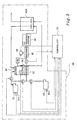
- FIG. 2 is an explanatory diagram showing a simplified configuration of a fuel cell system.
- Fuel cell system 60 has as its principal elements a methanol tank 61 for storing methanol, a water tank 62 for storing water, a burner 63 for generating combustion gas, a compressor 64 for compressing air, a vaporizer 65 provided with burner 63 and compressor 64, a reformer 66 for generating combustion gas by a reforming reaction, a CO reducing portion for reducing carbon monoxide (CO) concentration in the combustion gas, and a fuel cell 60A for producing electromotive force by an electrochemical reaction. Operation of these elements is controlled by control unit 70.
- Fuel cell 60A is solid polymer electrolyte fuel cell composed of a stack of cells each of which is constructed of an electrolyte membrane, cathode, anode and separator.
- the electrolyte membrane consists, for example, of a proton conductive ion exchange membrane fabricated of solid polymer electrolyte material such as fluororesin.
- the anode and cathode are both fabricated of carbon cloth woven from carbon fiber.
- the separator is fabricated of gas impermeable conducting material such as dense carbon rendered gas impermeable by compacting the carbon. Channels for fuel gas and oxidant gas are formed between anode and cathode.
- Methanol tank 61 is connected to vaporizer 65 by a line.
- a pump P2 situated on the line adjusts flow rate while supplying methanol fuel to the vaporizer 65.
- Water tank 62 is similarly connected to vaporizer 65 by a line.
- a pump P3 situated on the line adjusts flow rate while supplying water to the vaporizer 65.
- the methanol line and water line merge into a single line downstream from pumps P2, P3, and connects to vaporizer 65.
- Vaporizer 65 vaporizes the supplied methanol and water.
- Vaporizer 65 is provided with both burner 63 and compressor 64. Vaporizer 65 boils and vaporizes methanol and water by means of combustion gas supplied from burner 63.
- the fuel for burner 63 is methanol.
- Methanol tank 61 is connected by a line to burner 63 as well as to vaporizer 65. Methanol is supplied to burner 63 by a pump P1 situated on this line.
- Burner 63 is also supplied with leftover fuel waste gas not consumed in the electrochemical reaction in fuel cell 60A. Of methanol and fuel waste gas, burner 63 mainly burns the latter. Burner 63 combustion temperature is controlled on the basis of output of a sensor T1, and is maintained at about 800°C to 1000°C.
- Compressor 64 draws in air from outside the fuel cell system 60, compresses it, and supplies the compressed air to the anode side of fuel cell 60A.
- Vaporizer 65 and reformer 66 are connected by a line.
- Source fuel gas from vaporizer 65 i.e. mixed gas of methanol and water vapor
- Reformer 66 reforms the supplied source fuel gas consisting of methanol and water, to produce hydrogen-rich fuel gas.
- a temperature sensor T2 On the transport line leading from vaporizer 65 to reformer 66 there is provided a temperature sensor T2, and the amount of methanol supplied to burner 63 is controlled so that this temperature is at a constant level, typically about 250°C.
- Oxygen is involved in the reforming reaction in reformer 66.
- reformer 66 is provided with a blower 68 for supplying outside air.
- Reformer 66 and CO reducing portion 67 are connected by a line. Hydrogen-rich fuel gas from reformer 66 is supplied to CO reducing portion 67. In the reaction process in reformer 66 the combustion gas ordinarily contains a given amount of carbon monoxide (CO). CO reducing portion 67 reduces carbon monoxide concentration in the combustion gas. In a solid polymer electrolyte fuel cell carbon monoxide contained in combustion gas can hinder the anode reaction and depress fuel cell performance. CO reducing portion 67 oxidizes carbon monoxide present in the fuel gas to carbon dioxide, thereby reducing the concentration of carbon monoxide.
- CO carbon monoxide
- CO reducing portion 67 and the anode of fuel cell 60A are connected by a line.
- Fuel gas of reduced carbon monoxide concentration is supplied to the cell reaction on the cathode side of fuel cell 60A.
- a line for feeding in compressed air is connected to the cathode side of fuel cell 60A. This air is supplied as oxidant gas to the cell reaction at the anode side of fuel cell 60A.
- the fuel cell system 60 having the above arrangement can supply power by means of a chemical reaction using methanol and water.
- a fuel cell system 60 using methanol and water is provided, but the fuel cell system 60 is not limited to this, is being possible to employ instead various other arrangements such as those using gasoline/natural gas reforming, pure hydrogen etc.
- fuel cell system 60 shall be referred to in toto as fuel cell 60.
- Torque converter 30 (Fig. 1) is a known art drive power transmission mechanism utilizing a fluid.
- the input shaft of torque converter 30, i.e. the output shaft 13 of motor 20, and the output shaft 14 of torque converter 30 are not mechanically coupled, but can rather rotate with relative slippage.
- Torque converter 30 is provided with a lockup clutch that locks the two together under predetermined conditions so as to prevent slippage of the two rotary shafts. ON/OFF of the lockup clutch is controlled by control unit 70.
- Transmission 100 houses a plurality of gears, a clutch, one-way clutch, brake etc. and is a mechanism that by switching the change gear ratio converts the torque and rpm of the output shaft 14 of torque converter 30 transmitted to output shaft 15.
- a transmission capable of five forward speeds and one reverse speed.
- the gear of transmission 100 is set by control unit 70 depending on vehicle speed etc.
- the driver may manually operate a shift lever provided inside the vehicle to select shift position so as to enable gear shifting over a wide range.
- Control unit 70 is a one-chip microcomputer housing a CPU, RAM, ROM etc. wherein the CPU executes various control processes, described later, according to a program stored in ROM.
- Various input/output signals are connected to the control unit 70 to enable control to be realized.
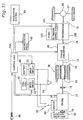
- Fig. 3 is an explanatory diagram showing input/output signal connections to control unit 70. Signals input to control unit 70 are shown on the left side in the drawing, and signals output from control unit are shown on the right side.
- Signals input to control unit 70 are signals from various switches and sensors. These signals include, for example, fuel cell temperature, fuel cell remaining fuel amount, battery remaining charge SOC, battery temperature, engine 10 water temperature, ignition switch, engine 10 rpm, ABS computer, defogger, air conditioning ON/OFF, vehicle speed, torque converter 30 oil temperature, shift position, side brake ON/OFF, foot brake depression, temperature of catalyst cleaning engine 10 exhaust, degree of degree of acceleration associated with depression of the accelerator pedal 55, cam angle sensor, drive power source brake power switch, and resolver signal. Control unit 70 inputs a large number of additional signals, but these are omitted in the drawing.
- Signals output by control unit 70 are signals for controlling engine 10, motor 20, torque converter 30, transmission 100 etc. These signals include for example a signal for controlling an electronic throttle valve, an ignition signal for controlling the ignition period of engine 10, a fuel injection signal for controlling fuel injection, a motor control signal for controlling operation of motor 20, a reduction gear control signal, an ABS actuator control signal, a control signal for power source changeover switch 84 of motor 20, a battery 50 control signal, a fuel cell system 60 control signal etc. Control unit 70 outputs a large number of additional signals, but these are omitted in the drawing.
- Control unit 70 drives the vehicle using these two selectively with reference to driving conditions, i.e. vehicle speed and torque. Selective use of the two is pre-established as a map stored in ROM in control unit 70.
- Fig. 4 is an explanatory diagram showing relationships of vehicle driving conditions and drive power source.
- Zone MG in the diagram is the zone of driving using motor 20 as the drive power source.
- the zone outside zone MG is the zone of driving using engine 10 as the drive power source (zone EG).
- the former shall be termed EV driving and the latter as engine driving.
- Fig. 1 it is possible to drive using both engine 10 and motor 20 as drive power sources, but this driving zone is not provided in the present example.
- the hybrid vehicle of this example when starting to drive with the ignition switch 88 on, initially accelerates in EV driving.
- input clutch 18 is off during driving.
- control unit 70 turns on input clutch 18 whereupon engine 10 is turned over by motor 20.
- Control 70 injects and ignites fuel under timing such that the rpm of engine 10 increases until reaching a predetermined value.
- driving in zone EG uses only engine 10 as the drive power source.
- control unit 70 shuts down all transistors of drive circuits 51, 52. As a result, motor 20 simply idles.
- Control unit 70 performs control to switch drive power source with reference to vehicle driving conditions in this manner, as well as performing a process of shifting gears in transmission 100. As with switching drive power source, gear shifting is done on the basis of a pre-established map for vehicle driving conditions. The map differs depending on shift position as well. In Fig. 5 there is shown a map corresponding to D position, 4 position, and 3 position. As shown by this map, control unit 70 executes gear shifting such that gear ratio becomes smaller as vehicle speed increases.
- Fig. 5 is a flow chart of a power output process routine in zone MG in Example 1.
- the process is executed when the vehicle is in the operating state, in other words, when ignition switch 88 is ON. When ignition switch 88 is OFF, operation of the entire vehicle is halted, so this process is not executed.
- the CPU inputs various sensor and switch signals (Step S100). Next, the CPU determines whether the fuel cell (FC: Fuel Cell) 60 is in a power generation-enabled state (Step S110).
- Step S120 Determining from fuel cell temperature, fuel cell remaining fuel amount etc. input to control unit 70 whether fuel cell 60 is in a power generation-enabled state, a setting process of a target output value for output by fuel cell 60 is performed (Step S120).
- battery 50 remaining charge SOC and degree of degree of acceleration are used.
- a target output value for fuel cell 60 is set with reference to these.
- degree of degree of acceleration is a parameter relating to power demand on the power supply device including fuel cell 60 and battery 50, and is determined by the amount of depression of the accelerator pedal 55.
- Fig. 6 is an explanatory diagram showing relationships of remaining charge SOC of battery 50, degree of degree of acceleration, and target output value of fuel cell 60 in Example 1.
- Power load place on the power supply device, associated with degree of acceleration, is indicated by thin line L.
- the target output value of fuel cell 60 is determined with reference to remaining charge SOC of battery 50 and degree of degree of acceleration.
- Line L1 shown by the solid line, line L2 shown by the dashed line, and line L3 shown by the dotted-dashed line correspond to different levels of remaining charge SOC of battery 50, becoming lower in this order.
- These relationships are stored as a table in the ROM of control unit 70.
- target output value of fuel cell 60 relative to remaining charge SOC of battery 50 and degree of degree of acceleration is set to three levels, but may be set to more levels, or vary continuously.
- the slope of the amount of change in target output value relative to the amount of change in degree of degree of acceleration is set so as to not exceed a predetermined maximum slope.
- This maximum value is a value enabling output of fuel cell 60 to track target output value, even where degree of degree of acceleration changes suddenly.
- target output value is set higher than power demand, and in the zone of relatively high degree of degree of acceleration (zone Y in the drawing) target output value is set lower than power demand. That is, output of fuel cell 60 is limited to within zone A shown in the drawing.
- the fuel cell 60 of this example has high generation efficiency in zone A shown in the drawing. Therefore, by setting target output value in this way, fuel cell 60 may be utilized efficiently.
- target output value for fuel cell 60 is set to a higher value the lower the remaining charge SOC of battery 50.
- Step S130 When a target output value for fuel cell 60 is set, fuel cell 60 outputs power in response thereto (Step S130 in Fig. 5). Battery 50 then charges/discharges so as to compensate for the difference between the output of fuel cell 60 and the power demand corresponding to degree of acceleration (Step S140).
- Step S140 These controls are performed according to a control signal for the power supply changeover switch 84 output by control unit 70. That is, where charging/discharging of battery 50 is required, connections among battery 50, motor 20 and fuel cell 60 are switched by changeover switch 84, and charging/discharging is performed in response to the voltage difference.
- Step S110 of Fig. 5 if fuel cell 60 is in a power generation-disabled state, it is determined whether the remaining charge SOC of battery 50 is at or above a control lower limit LoS% (Step S150). If the remaining charge SOC of battery 50 is below control lower limit LoS%, engine 10 is started and drive power is output (Step S160). If the remaining charge SOC of battery 50 is at or above control lower limit LoS%, output is with the battery 50 as the principal power source (Step S170).
- Fig. 7 is a timing chart showing as one example change in fuel cell 60 target output value relative to degree of acceleration; actual output from fuel cell 60; and output from battery 50 in Example 1.
- target output value for fuel cell 60 also increases sharply according to the table (see Fig. 6).
- target output value and power demand do not necessarily match.
- Target output value at time t2 is set to a larger value than power demand needed for driving.
- the output of fuel cell 60 due to low responsiveness, cannot track the sudden increase in target output value, and increases at maximum slope.
- battery 50 outputs so as to compensate for the deficit in output of fuel cell 60. By so doing the remaining charge SOC of battery 50 drops.
- the rate of change of the target output value is smaller than the output responsiveness of fuel cell 60 and can be met by it, so the output of fuel cell 60 increases in association with the target output value.
- Battery 50 outputs so as to compensate for the deficit in output of fuel cell 60 until output of fuel cell 60 reaches target output value at time t3'. Subsequent to time t3' the output of fuel cell 60 exceeds power demand, so the excess power is used to charge the battery 50. Battery 50 at time t3' -t4 does not output, since the power demand can be output by output of the fuel cell 60 alone.
- control unit 70 detects that the remaining charge SOC of battery 50 has been sufficiently charged, and returns to the normal target output value. Output of fuel cell 60, the rate of change of the target output value being smaller than the output responsiveness of the fuel cell so that it can be met, declines in association with the target output value. Battery 50 does not output, since the power demand associated with the degree of acceleration can be output by output of the fuel cell 60 alone.
- Fig. 8 is a timing chart showing as one example change in fuel cell 60 target output value relative to degree of acceleration; actual output from fuel cell 50; and output from battery 50 in a comparative example.
- Target output value of the fuel cell 60 of the comparative example is set to equal power demand associated with degree of acceleration.
- the degree of acceleration increases.
- the target output value for fuel cell 60 increases in association with the degree of acceleration. Since the rate of change of the target output value is smaller than the output responsiveness of the fuel cell, the output of fuel cell 60 increases/decreases to track the target output value. Battery 50 does not output, since the power demand associated with the degree of acceleration can be output by output of the fuel cell 60 alone.
- battery 50 outputs so as to compensate for a deficit in output by fuel cell 60, so that responsiveness is assured.
- target output value for fuel cell 60 is set to equal the power demand
- the output of fuel cell 60 will not be able to track the target output value, resulting in instances in which stable control with reference to target output value is not possible.
- remaining charge SOC cannot be assured, and in the event that remaining charge SOC goes below a predetermined value, it may be necessary in some instances to run the engine 10 for charging.
- Example 1 on the other hand, even where there are large fluctuations in the degree of acceleration, fluctuation in target output value for fuel cell 60 is smaller than output responsiveness, enabling output of fuel cell 60 to be controlled in a stable manner. As a result, output responsiveness to degree of acceleration may be assured while effectively utilizing fuel cell 60 as the power supply source. Additionally, as target output value is set with reference to remaining charge SOC of battery 50, battery 50 may be charged quickly and effectively. As a result, capacity of battery 50 can be reduces and the power supply device can be made smaller and lighter.
- Example 1 degree of acceleration and remaining charge SOC of battery 50 are sampled at fixed intervals, and target output value for fuel cell 60 established progressively with reference to these.
- Example 2 the rate of change in degree of acceleration is calculated from the degree of acceleration sampled at fixed intervals, and the setting process of target output value for fuel cell 60 is modified with reference thereto.
- the flow of drive power process routines other than the setting process of target output value for fuel cell 60 is similar.
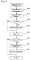
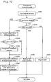
- Fig. 9 is a flow chart of a setting process of target output value for fuel cell 60 in Example 2.
- CPU first reads the degree of acceleration (Step S200).
- a rate of change r of degree of acceleration is then calculated from the previously read degree of acceleration, currently read degree of acceleration, and sampling time (Step S210), and the absolute value of the rate of change
- the target output value set here is the target output value when remaining charge SOC of battery 50 is in the normal state in Example 1 shown in Fig. 6. It should be noted that the table storing relationships of degree of acceleration and target output value for fuel cell 60 (see Fig. 6) can be set arbitrarily. If the absolute value of the rate of change
- Threshold value Rth can be set arbitrarily. For example, threshold value Rth may be fixed. Alternatively, it may be progressively modified through decisions made on the basis of the trend of driver operation of the accelerator pedal 55, or past fuel cell 60 and battery operating conditions. Threshold value Rth may assume different values when the rate of change in degree of acceleration is positive versus when it is negative.
- Step S240 the remaining charge SOC of battery 50 is read (Step S240), and it is determined whether the remaining charge SOC of battery 50 is at or above a predetermined value LO% (Step S250). If the remaining charge SOC of battery 50 is at or above predetermined value LO%, it is decided that the remaining charge SOC of battery 50 is adequate, and this process is terminated. If the remaining charge SOC of battery 50 is below predetermined value LO%, a correction value for increasing the target output value is set so that battery 50 can be charged with output from fuel cell 60 (Step S260). This is added to arrive at a new target output value (Step S270).
- Predetermined value LO can be set arbitrarily. However, if LO is set too high, correction of target output value in Steps S260, S270 will be performed frequently, in some instances making stable operation of fuel cell 60 impossible. On the other hand if LO is set too low, battery 50 will be used frequently and in some instances fuel cell 60 cannot be utilized efficiently.
- Fig. 10 is a timing chart showing as one example change in fuel cell 60 target output value relative to degree of acceleration; actual output from fuel cell 60; and output from battery 50 in Example 2.
- target output value for fuel cell 60, fuel cell 60 output and battery 50 output are also 0.
- the degree of acceleration decreases sharply.
- the absolute value of the rate of change in degree of acceleration exceeds threshold value Rth.
- the target output value for fuel cell 60 also decreases sharply in association with the degree of acceleration.
- the output of fuel cell 60 declines to track the target output value.
- Battery 50 does not output, since the power demand associated with the degree of acceleration can be output by output of the fuel cell 60 alone.
- the degree of acceleration decreases.
- the absolute value of the rate of change in degree of acceleration is at or below threshold value Rth.
- the target output value for fuel cell 60 is held at the value of time t4 (or t5) until time t5' at which control unit 70 senses that the remaining charge SOC of battery 50 is below LO%.
- Fuel cell 60 outputs with reference to target output value until time t5'.
- Battery 50 outputs so as to compensate for the deficit in output of fuel cell 60.
- control unit 70 senses that the remaining charge SOC of battery 50 is below LO%. Thereupon, while degree of acceleration is decreased at this time, the target output value for fuel cell 60 is corrected to high so that battery 50 can be charged rapidly. The output of fuel cell 60, due to low responsiveness, cannot track this increase in target output value, and increases at maximum slope.
- Output of fuel cell 60 at time t5' and subsequently shown in the drawing is greater than the power demand, so the excess power is used to perform charging of battery 50. While not shown in the drawing, also where the degree of acceleration declines slowly after increasing sharply, i.e., where the absolute value of the rate of change in degree of acceleration is at or below threshold value Rth, the target output value for fuel cell 60 does not decline, so charging of the battery 50 can be performed.
- Example 2 as regards the fuel cell 60 having low output responsiveness relative to degree of acceleration, control for stable operation of fuel cell 60 is performed by making it less sensitive to degree of acceleration.
- the battery 50 which has good output responsiveness, is used for sudden changes in degree of acceleration. In this way as well, output responsiveness relative to degree of acceleration can be ensured, excessive charge/ discharge of the storage portion can be minimized, and fuel cell 60 can be utilized effectively as a power supply source.
- the hybrid vehicle of Example 3 is equipped with a navigation system.
- Fig. 11 is a simplified configuration diagram of the hybrid vehicle of Example 3.
- Navigation system 90 is connected to a control unit 70B, and to control unit 70B is input information about the route over which the vehicle will travel in the future.
- the arrangement of other hardware is similar to Example 1. Between Example 1 and Example 3, the power output process differs in part.
- Fig. 12 is a flow chart of a power output process routine in Example 3.
- the CPU inputs various sensor and switch signals (Step S300).
- the CPU determines whether fuel cell 60 is in a power generation-enabled state (Step S310).
- Step S320 a setting process of a target output value for output by fuel cell 60 is performed (Step S320). This process is the same as in Example 1.
- Step S330 a decision as to whether or not the navigation system 90 is being used in driving. If not driving using the navigation system 90, fuel cell 60 outputs power with reference to target output value just as in Example 1 (Step S350), and battery 50 charges/discharges so as to compensate for the difference between the output of fuel cell 60 and the power demand corresponding to degree of acceleration (Step S360). Where driving using the navigation system 90, a correction process for navigation system driving use is performed on target output value.
- Step S330 In the event of traffic congestion or in the event of being stopped at light, etc., the determination may be made in Step S330 that driving is not using the navigation system.
- Fig. 13 is a flow chart of a target output value correction process for navigation system driving use.
- the CPU reads route information from navigation system 90 (Step S400).
- This route information includes information relating to upgrade or downgrade slope, or information for a freeway etc.
- Power demand at a predetermined time in the future is then estimated based on this route information (Step S410). For example, if CPU should detect from navigation system 90 that there is a future upgrade, the power needed to climb the upgrade will be estimated.
- Target output value at a predetermined time in the future is then set based on the estimated future power demand (Step S420).
- target output value is corrected using this future target output value, the target output value set in Step 320 of Fig. 12, target output value at predetermined time in the future, and output characteristics of fuel cell 60 (maximum slope outputtable) (Step S430).
- Fig. 14 is a timing chart showing as an example change in fuel cell 60 target output value associated with degree of acceleration, actual output of fuel cell 60, and battery 50 output.
- Degree of acceleration is constant up to time t2 and requires power PW1.
- PW1 power
- time t6 and thereafter it is constant.
- control unit 70 can recognize, prior to time t5 nearing the downgrade, that there is a future downgrade. From current target output value PW2, future target output value PW1 and output characteristics of fuel cell 60, it is recognized that even if target output value at time t4 is reduced to PW2 and battery 50 power is consumed, [the battery] can be recharged on the downgrade, and it corrects the target output value [accordingly]. At time t4 -t6 fuel cell 60 output in insufficient for power demand, the deficit being made up for by output from the battery 50.
- Step S310 of Fig. 12 if fuel cell 60 is in a generation-disabled state, it is determined whether the remaining charge SOC of battery 50 is at or above the control lower limit LoS% (Step S370). If the remaining charge SOC of battery 50 is below the control lower limit LoS%, the engine 10 is started and drive power is output (Step S380). If the remaining charge SOC of battery 50 is at or above the control lower limit LoS%, battery 50 outputs as the main power source (Step S390).
- fuel cell 60 in a vehicle having an on-board navigation system 90, fuel cell 60 can be utilized effectively as a power supply source while ensuring output responsiveness to the degree of acceleration.
- Example 1 relationships of battery 50 remaining charge SOC, degree of acceleration, and target output value for fuel cell 60 are stored as a table, but instead target output value for fuel cell 60 could be calculated using battery 50 remaining charge SOC and degree of acceleration as parameters.
- Example 2 it is decided from the rate of change of degree of acceleration whether or not to perform correction of the target output value for fuel cell 60, but instead correction of the target output value for fuel cell 60 could be performed based on the rate of change of degree of acceleration and the amount of change in degree of acceleration.
- Example 2 hereinabove the rate of change in degree of acceleration is calculated from degree of acceleration sampled at fixed intervals, but rate of change in degree of acceleration could instead be sensed directly using a sensor.
- Fig. 15 is a simplified configuration diagram of an electric vehicle.
- This electric vehicle comprises a fuel cell 60B, battery 50B, control unit 70B, changeover switch 84B, inverter 52B, motor 20B, accelerator pedal 55B, differential gear 16B, axle 17B etc.
- auxiliary drive motor 82, transmission 100 etc. shown in Fig. 1 are omitted.
- a battery 50 is used as the rechargeable storage portion, but a capacitor or other such storage means could be used instead.
- the invention can be utilized to control a power supply device having a fuel cell and storage portion as the power source.
Landscapes
- Engineering & Computer Science (AREA)
- Chemical & Material Sciences (AREA)
- Transportation (AREA)
- Sustainable Development (AREA)
- Sustainable Energy (AREA)
- Life Sciences & Earth Sciences (AREA)
- Mechanical Engineering (AREA)
- Combustion & Propulsion (AREA)
- Chemical Kinetics & Catalysis (AREA)
- General Chemical & Material Sciences (AREA)
- Electrochemistry (AREA)
- Manufacturing & Machinery (AREA)
- Power Engineering (AREA)
- Automation & Control Theory (AREA)
- Artificial Intelligence (AREA)
- Health & Medical Sciences (AREA)
- Computing Systems (AREA)
- Evolutionary Computation (AREA)
- Fuzzy Systems (AREA)
- Medical Informatics (AREA)
- Software Systems (AREA)
- Theoretical Computer Science (AREA)
- Human Computer Interaction (AREA)
- Fuel Cell (AREA)
- Electric Propulsion And Braking For Vehicles (AREA)
- Hybrid Electric Vehicles (AREA)
- Control Of Vehicle Engines Or Engines For Specific Uses (AREA)
- Charge And Discharge Circuits For Batteries Or The Like (AREA)
Applications Claiming Priority (3)
| Application Number | Priority Date | Filing Date | Title |
|---|---|---|---|
| JP2000141822 | 2000-05-15 | ||
| JP2000141822A JP5140894B2 (ja) | 2000-05-15 | 2000-05-15 | 燃料電池と充放電可能な蓄電部とを利用した電力の供給 |
| PCT/JP2001/003374 WO2001089015A1 (fr) | 2000-05-15 | 2001-04-19 | Alimentation en electricite utilisant une pile a combustible et accumulateur chargeable/dechargeable |
Publications (3)
| Publication Number | Publication Date |
|---|---|
| EP1286405A1 true EP1286405A1 (fr) | 2003-02-26 |
| EP1286405A4 EP1286405A4 (fr) | 2005-08-17 |
| EP1286405B1 EP1286405B1 (fr) | 2006-10-25 |
Family
ID=18648888
Family Applications (1)
| Application Number | Title | Priority Date | Filing Date |
|---|---|---|---|
| EP01921929A Expired - Lifetime EP1286405B1 (fr) | 2000-05-15 | 2001-04-19 | Alimentation en electricite utilisant une pile a combustible et accumulateur chargeable/dechargeable |
Country Status (8)
| Country | Link |
|---|---|
| US (2) | US7301302B2 (fr) |
| EP (1) | EP1286405B1 (fr) |
| JP (1) | JP5140894B2 (fr) |
| KR (1) | KR100497834B1 (fr) |
| CN (1) | CN1237640C (fr) |
| CA (1) | CA2408785C (fr) |
| DE (1) | DE60124090T8 (fr) |
| WO (1) | WO2001089015A1 (fr) |
Cited By (9)
| Publication number | Priority date | Publication date | Assignee | Title |
|---|---|---|---|---|
| WO2004000597A1 (fr) * | 2002-06-20 | 2003-12-31 | Daimlerchrysler Ag | Vehicule automobile a entrainement hybride |
| FR2845525A1 (fr) * | 2002-10-03 | 2004-04-09 | Renault Sa | Procede de recuperation d'energie a bord d'un vehicule equipe d'une pile a combustible a reformeur |
| EP1470943A2 (fr) * | 2003-04-24 | 2004-10-27 | Delphi Technologies, Inc. | Procédé et appareil de fournissage de puissance motrice dans un véhicule hybride |
| WO2004108468A1 (fr) * | 2003-06-03 | 2004-12-16 | Toyota Jidosha Kabushiki Kaisha | Dispositif de commande d'une batterie a bord et procede de commande |
| FR2856523A1 (fr) * | 2003-06-20 | 2004-12-24 | Air Liquide | Protection d'une pile a combustible |
| WO2005018979A1 (fr) * | 2003-08-25 | 2005-03-03 | Toyota Jidosha Kabushiki Kaisha | Systeme de pile a combustible et vehicule electrique le comportant |
| WO2005119897A1 (fr) * | 2004-06-03 | 2005-12-15 | Toyota Jidosha Kabushiki Kaisha | Dispositif de conversion de puissance et vehicule equipe dudit dispositif |
| FR2906936A1 (fr) * | 2006-10-09 | 2008-04-11 | Renault Sas | Dispositif et procede de gestion de l'alimentation en courant electrique d'un moteur electrique de vehicule automobile |
| WO2013045139A1 (fr) * | 2011-09-26 | 2013-04-04 | Bayerische Motoren Werke Aktiengesellschaft | Procédé permettant de faire fonctionner un système d'énergie électrique d'un véhicule à moteur, constitué d'une installation de piles à combustible, d'un accumulateur et d'un moteur électrique |
Families Citing this family (81)
| Publication number | Priority date | Publication date | Assignee | Title |
|---|---|---|---|---|
| US6892840B2 (en) * | 1999-05-05 | 2005-05-17 | Daniel J. Meaney, Jr. | Hybrid electric vehicle having alternate power sources |
| JP3721947B2 (ja) * | 2000-05-30 | 2005-11-30 | 日産自動車株式会社 | 燃料電池システムの制御装置 |
| JP3624831B2 (ja) * | 2000-12-28 | 2005-03-02 | 株式会社デンソー | 車両用電源装置及びエンジン駆動規制支援装置 |
| DE10152809B4 (de) * | 2001-10-25 | 2004-07-22 | Daimlerchrysler Ag | Verfahren zum Betreiben eines Hybridantriebssystems |
| JP2003189409A (ja) * | 2001-12-21 | 2003-07-04 | Toyota Motor Corp | 電動機搭載車両 |
| US7049015B2 (en) * | 2002-04-12 | 2006-05-23 | Motorola, Inc. | Method of operating a fuel cell power source |
| US7470483B2 (en) | 2002-12-11 | 2008-12-30 | Panasonic Corporation | Electrolyte membrane-electrode assembly for fuel cell and operation method of fuel cell using the same |
| US20040253489A1 (en) * | 2003-06-12 | 2004-12-16 | Horgan Thomas J. | Technique and apparatus to control a fuel cell system |
| US7532987B2 (en) * | 2003-08-28 | 2009-05-12 | Panasonic Corporation | Fuel-cell power generation system and control method therefor |
| JP3912362B2 (ja) * | 2003-10-30 | 2007-05-09 | 日産自動車株式会社 | ハイブリッド車両の制御装置 |
| JP4525112B2 (ja) * | 2004-03-08 | 2010-08-18 | 日産自動車株式会社 | 燃料電池車両の制御装置 |
| JP4241593B2 (ja) * | 2004-12-08 | 2009-03-18 | トヨタ自動車株式会社 | ハイブリッドシステム |
| JP4857564B2 (ja) * | 2005-01-24 | 2012-01-18 | 日産自動車株式会社 | 燃料電池システム制御装置及び燃料電池システム制御方法 |
| JP2006210100A (ja) * | 2005-01-27 | 2006-08-10 | Toyota Motor Corp | 電源装置 |
| US7543454B2 (en) | 2005-03-14 | 2009-06-09 | Zero Emission Systems, Inc. | Method and auxiliary system for operating a comfort subsystem for a vehicle |
| US7600595B2 (en) * | 2005-03-14 | 2009-10-13 | Zero Emission Systems, Inc. | Electric traction |
| JP4353154B2 (ja) * | 2005-08-04 | 2009-10-28 | トヨタ自動車株式会社 | 燃料電池自動車 |
| JP4946028B2 (ja) * | 2005-12-13 | 2012-06-06 | トヨタ自動車株式会社 | 燃料電池システム及び移動体 |
| JP2007188712A (ja) * | 2006-01-12 | 2007-07-26 | Yamaha Motor Co Ltd | 燃料電池システムおよびそれを備えた電動車 |
| US7921945B2 (en) | 2006-02-21 | 2011-04-12 | Clean Emissions Technologies, Inc. | Vehicular switching, including switching traction modes and shifting gears while in electric traction mode |
| JP4509051B2 (ja) * | 2006-03-13 | 2010-07-21 | 三洋電機株式会社 | ハイブリッド電源装置 |
| US8565969B2 (en) | 2007-04-03 | 2013-10-22 | Clean Emissions Technologies, Inc. | Over the road/traction/cabin comfort retrofit |
| JP4529959B2 (ja) * | 2006-08-24 | 2010-08-25 | マツダ株式会社 | ハイブリッド車両の制御装置 |
| JP4380676B2 (ja) * | 2006-09-12 | 2009-12-09 | トヨタ自動車株式会社 | 移動体 |
| JP4379922B2 (ja) * | 2006-09-12 | 2009-12-09 | トヨタ自動車株式会社 | 移動体 |
| US7914935B2 (en) * | 2006-09-29 | 2011-03-29 | GM Global Technology Operations LLC | Method for managing fuel cell power increases using air flow feedback delay |
| US7921950B2 (en) | 2006-11-10 | 2011-04-12 | Clean Emissions Technologies, Inc. | Electric traction retrofit |
| JP4179383B2 (ja) * | 2007-02-13 | 2008-11-12 | トヨタ自動車株式会社 | 駆動力発生システムおよびそれを備える車両、ならびにその制御方法 |
| JP5110913B2 (ja) * | 2007-02-28 | 2012-12-26 | 三洋電機株式会社 | 電源装置 |
| JP5036416B2 (ja) * | 2007-06-15 | 2012-09-26 | トヨタ自動車株式会社 | 電源システムおよびそれを備えた車両、ならびに充放電制御方法 |
| US8299756B2 (en) * | 2007-11-01 | 2012-10-30 | General Electric Company | System and method for battery control |
| CN102083644B (zh) | 2008-03-19 | 2015-04-01 | 无污染发射技术股份有限公司 | 电动牵引系统及其方法 |
| US8154242B2 (en) * | 2008-03-26 | 2012-04-10 | GM Global Technology Operations LLC | Method of fully charging an electrical energy storage device using a lower voltage fuel cell system |
| US9758146B2 (en) | 2008-04-01 | 2017-09-12 | Clean Emissions Technologies, Inc. | Dual mode clutch pedal for vehicle |
| TW201014965A (en) * | 2008-10-03 | 2010-04-16 | Demand Internat Corp | Device to save gasoline consumption |
| US20100109437A1 (en) * | 2008-11-05 | 2010-05-06 | Fattic Gerald T | Battery pack disconnection method for a hybrid vehicle |
| US9631528B2 (en) | 2009-09-03 | 2017-04-25 | Clean Emissions Technologies, Inc. | Vehicle reduced emission deployment |
| JP5101583B2 (ja) * | 2009-09-16 | 2012-12-19 | 本田技研工業株式会社 | 燃料電池車両 |
| EP2385572A4 (fr) * | 2009-12-10 | 2013-04-03 | Panasonic Corp | Système de pile à combustible et dispositif électronique |
| JP5611336B2 (ja) * | 2010-05-25 | 2014-10-22 | 三菱電機株式会社 | 電力情報管理装置及び電力情報管理システム |
| US8626369B2 (en) | 2010-08-10 | 2014-01-07 | Tesla Motors, Inc. | Charge rate modulation of metal-air cells as a function of ambient oxygen concentration |
| US8543270B2 (en) * | 2010-08-10 | 2013-09-24 | Tesla Motors, Inc. | Efficient dual source battery pack system for an electric vehicle |
| JP5409702B2 (ja) * | 2011-05-18 | 2014-02-05 | 本田技研工業株式会社 | 燃料電池車両 |
| KR101510066B1 (ko) | 2011-12-09 | 2015-04-14 | 유나이티드 테크놀로지스 코포레이션 | 연료전지 어셈블리 및 제어 방법 |
| US9580062B2 (en) * | 2012-01-10 | 2017-02-28 | Ford Global Technologies, Llc | Method for increasing fuel economy of plug-in hybrid electric vehicles |
| EP2824322B1 (fr) * | 2012-03-08 | 2016-11-16 | Mitsubishi Heavy Industries, Ltd. | Dispositif de régulation de sortie et méthode de régulation de sortie pour éolienne |
| CN104584362B (zh) | 2012-08-16 | 2017-11-21 | 日产自动车株式会社 | 电力供给系统以及电力供给系统的控制方法 |
| KR101852888B1 (ko) | 2013-03-26 | 2018-06-04 | 한화지상방산 주식회사 | 하이브리드 전력 공급 시스템의 동작 방법 |
| KR101439059B1 (ko) * | 2013-10-29 | 2014-11-04 | 현대자동차주식회사 | 저전압 배터리 충전 제어 방법 및 장치 |
| US9079581B1 (en) * | 2014-01-16 | 2015-07-14 | Ford Global Technologies, Llc | Hybrid vehicle and method of operation |
| JP2015227712A (ja) * | 2014-06-02 | 2015-12-17 | トヨタ自動車株式会社 | 車両用駆動装置 |
| US9587559B2 (en) * | 2014-06-09 | 2017-03-07 | Schaeffler Technologies AG & Co. KG | Accessories drive system including a transmission driven motor generator unit |
| JP6053722B2 (ja) * | 2014-06-09 | 2016-12-27 | 本田技研工業株式会社 | 燃料電池車両 |
| CN106575780B (zh) * | 2014-07-24 | 2019-12-03 | 日产自动车株式会社 | 燃料电池系统 |
| US9493090B2 (en) * | 2014-08-14 | 2016-11-15 | Fca Us Llc | Dynamic battery system voltage control through mixed dynamic series and parallel cell connections |
| JP6223406B2 (ja) * | 2015-11-28 | 2017-11-01 | 本田技研工業株式会社 | 電力供給システム |
| JP6284921B2 (ja) * | 2015-11-28 | 2018-02-28 | 本田技研工業株式会社 | 電力供給システム及び輸送機器、並びに、電力伝送方法 |
| US9764633B1 (en) * | 2016-03-16 | 2017-09-19 | Caterpillar Inc. | Electric drivetrain system and method having a single speed ratio direct drive |
| JP6935664B2 (ja) * | 2016-05-02 | 2021-09-15 | 株式会社豊田中央研究所 | 燃料電池を備える移動体 |
| JP2017204407A (ja) * | 2016-05-12 | 2017-11-16 | トヨタ自動車株式会社 | 燃料電池システム及びその制御方法 |
| JP6761203B2 (ja) * | 2016-06-17 | 2020-09-23 | 三菱自動車工業株式会社 | 車両用燃料電池の電力制御装置 |
| US10320207B2 (en) * | 2016-06-23 | 2019-06-11 | Faraday & Future Inc. | Systems and methods for intelligently charging battery cells |
| CN106515768A (zh) * | 2016-11-02 | 2017-03-22 | 上海钧希新能源科技有限公司 | 一种基于甲醇燃料电池的列车空调系统 |
| US10683002B2 (en) * | 2017-06-27 | 2020-06-16 | Toyota Motor Engineering & Manufacturing North America, Inc. | Efficient acceleration from surrounding vehicles |
| JP7251913B2 (ja) * | 2017-06-28 | 2023-04-04 | トヨタ自動車株式会社 | 機械の設計方法 |
| EP3670238B1 (fr) * | 2017-08-14 | 2022-01-19 | Nissan Motor Co., Ltd. | Système d'alimentation électrique et son procédé de fonctionnement |
| US11916378B2 (en) | 2018-08-30 | 2024-02-27 | Bloom Energy Corporation | Power source communication with downstream device by changing output voltage on a power bus |
| DE102019207117A1 (de) * | 2019-05-16 | 2020-11-19 | Robert Bosch Gmbh | Brennstoffzellensystem mit zwei Brennstoffzelleneinheiten die unabhängig voneinander betrieben werden können |
| US11258294B2 (en) | 2019-11-19 | 2022-02-22 | Bloom Energy Corporation | Microgrid with power equalizer bus and method of operating same |
| DE102020114269A1 (de) | 2020-05-28 | 2021-12-02 | Audi Aktiengesellschaft | Verfahren zum Betreiben eines Brennstoffzellen-Fahrzeuges sowie Brennstoffzellen-Fahrzeug |
| CN111731156B (zh) * | 2020-06-12 | 2022-07-05 | 大运汽车股份有限公司 | 一种氢燃料电池汽车能量控制方法 |
| CN113829955B (zh) * | 2020-06-24 | 2023-07-14 | 北京亿华通科技股份有限公司 | 燃料电池车的能量管理方法 |
| EP4315464A2 (fr) * | 2021-04-01 | 2024-02-07 | Zeroavia Ltd. | Système de gestion prédictive de piles à combustible |
| CN113147514B (zh) * | 2021-04-28 | 2023-12-15 | 黄冈格罗夫氢能汽车有限公司 | 一种多能量源氢燃料电池汽车能量管理控制方法及系统 |
| CN113525179B (zh) * | 2021-08-27 | 2024-01-12 | 潍柴动力股份有限公司 | 一种燃料电池的动态响应控制方法 |
| CN113511111B (zh) * | 2021-09-01 | 2024-04-16 | 潍柴动力股份有限公司 | 燃料电池系统控制方法、装置、设备及可读存储介质 |
| JP2023073113A (ja) * | 2021-11-15 | 2023-05-25 | 株式会社小松製作所 | 制御システム、作業車両管理装置、制御装置、および作業車両の制御方法 |
| CN114683969B (zh) * | 2022-04-12 | 2024-04-16 | 潍柴动力股份有限公司 | 一种燃料电池发动机加载控制方法、装置及设备 |
| DE102022209484A1 (de) * | 2022-09-12 | 2024-03-14 | Psa Automobiles Sa | Stromversorgungssystem |
| CN115991123B (zh) * | 2023-03-22 | 2023-07-18 | 长安新能源南京研究院有限公司 | 一种功率负荷状态识别方法、系统、设备和介质 |
| CN116488312B (zh) * | 2023-06-25 | 2023-09-22 | 江西五十铃汽车有限公司 | 电池电量管理方法、系统、计算机及可读存储介质 |
Citations (9)
| Publication number | Priority date | Publication date | Assignee | Title |
|---|---|---|---|---|
| US4839246A (en) * | 1987-05-20 | 1989-06-13 | Fuji Electric Co., Ltd. | Generator system utilizing a fuel cell |
| US5334463A (en) * | 1991-11-29 | 1994-08-02 | Sanyo Electric Co., Ltd. | Hybrid fuel battery system and the operation method thereof |
| EP0769402A2 (fr) * | 1995-10-20 | 1997-04-23 | Toyota Jidosha Kabushiki Kaisha | Commande pour véhicule hybride |
| US5631532A (en) * | 1994-02-24 | 1997-05-20 | Kabushikikaisha Equos Research | Fuel cell/battery hybrid power system for vehicle |
| US5780981A (en) * | 1995-11-02 | 1998-07-14 | Daimler-Benz Ag | Process for dynamically adjusting the power for a vehicle having a fuel cell |
| US5877600A (en) * | 1995-11-08 | 1999-03-02 | Daimler-Benz Ag | Process for determining a desired load value for a load-dependent current generating system in an electric vehicle |
| US5991670A (en) * | 1995-12-29 | 1999-11-23 | Dbb Fuel Cell Engines Gmbh | Power control system for a fuel cell powered vehicle |
| EP1055545A2 (fr) * | 1999-05-26 | 2000-11-29 | Toyota Jidosha Kabushiki Kaisha | Objet mobile avec piles à combustible intégrées et sa méthode de contrôle |
| EP1091437A1 (fr) * | 1998-06-25 | 2001-04-11 | Toyota Jidosha Kabushiki Kaisha | Systeme de pile a combustible et procede de commande de pile |
Family Cites Families (11)
| Publication number | Priority date | Publication date | Assignee | Title |
|---|---|---|---|---|
| JPH03276573A (ja) * | 1990-03-26 | 1991-12-06 | Fuji Electric Co Ltd | 車両搭載用燃料電池の制御方式 |
| JP2892817B2 (ja) * | 1990-11-19 | 1999-05-17 | 株式会社日立製作所 | 変速制御方法および変速機 |
| JPH05182675A (ja) * | 1991-07-04 | 1993-07-23 | Shimizu Corp | 燃料電池の出力制御方法 |
| US5318142A (en) * | 1992-11-05 | 1994-06-07 | Ford Motor Company | Hybrid drive system |
| JP3185630B2 (ja) * | 1995-07-24 | 2001-07-11 | トヨタ自動車株式会社 | 電気自動車用発電装置の制御装置 |
| JPH09306531A (ja) | 1996-05-21 | 1997-11-28 | Toyota Motor Corp | 燃料電池システム |
| JPH10271706A (ja) | 1997-03-24 | 1998-10-09 | Toyota Motor Corp | 電源装置および電気自動車 |
| JP4031555B2 (ja) * | 1997-05-23 | 2008-01-09 | トヨタ自動車株式会社 | ガス供給装置 |
| DE19747265B4 (de) * | 1997-10-25 | 2010-11-04 | Zf Friedrichshafen Ag | Hybridantrieb für ein Fahrzeug |
| US6577334B1 (en) * | 1998-02-18 | 2003-06-10 | Kabushikikaisha Equos Research | Vehicle control |
| US6311484B1 (en) * | 2000-02-22 | 2001-11-06 | Engelhard Corporation | System for reducing NOx transient emission |
-
2000
- 2000-05-15 JP JP2000141822A patent/JP5140894B2/ja not_active Expired - Lifetime
-
2001
- 2001-04-19 US US10/275,941 patent/US7301302B2/en not_active Expired - Lifetime
- 2001-04-19 WO PCT/JP2001/003374 patent/WO2001089015A1/fr active IP Right Grant
- 2001-04-19 CN CNB018094686A patent/CN1237640C/zh not_active Expired - Lifetime
- 2001-04-19 CA CA002408785A patent/CA2408785C/fr not_active Expired - Fee Related
- 2001-04-19 DE DE60124090T patent/DE60124090T8/de active Active
- 2001-04-19 EP EP01921929A patent/EP1286405B1/fr not_active Expired - Lifetime
- 2001-04-19 KR KR10-2002-7015255A patent/KR100497834B1/ko active IP Right Grant
-
2007
- 2007-06-08 US US11/760,210 patent/US7583052B2/en not_active Expired - Lifetime
Patent Citations (9)
| Publication number | Priority date | Publication date | Assignee | Title |
|---|---|---|---|---|
| US4839246A (en) * | 1987-05-20 | 1989-06-13 | Fuji Electric Co., Ltd. | Generator system utilizing a fuel cell |
| US5334463A (en) * | 1991-11-29 | 1994-08-02 | Sanyo Electric Co., Ltd. | Hybrid fuel battery system and the operation method thereof |
| US5631532A (en) * | 1994-02-24 | 1997-05-20 | Kabushikikaisha Equos Research | Fuel cell/battery hybrid power system for vehicle |
| EP0769402A2 (fr) * | 1995-10-20 | 1997-04-23 | Toyota Jidosha Kabushiki Kaisha | Commande pour véhicule hybride |
| US5780981A (en) * | 1995-11-02 | 1998-07-14 | Daimler-Benz Ag | Process for dynamically adjusting the power for a vehicle having a fuel cell |
| US5877600A (en) * | 1995-11-08 | 1999-03-02 | Daimler-Benz Ag | Process for determining a desired load value for a load-dependent current generating system in an electric vehicle |
| US5991670A (en) * | 1995-12-29 | 1999-11-23 | Dbb Fuel Cell Engines Gmbh | Power control system for a fuel cell powered vehicle |
| EP1091437A1 (fr) * | 1998-06-25 | 2001-04-11 | Toyota Jidosha Kabushiki Kaisha | Systeme de pile a combustible et procede de commande de pile |
| EP1055545A2 (fr) * | 1999-05-26 | 2000-11-29 | Toyota Jidosha Kabushiki Kaisha | Objet mobile avec piles à combustible intégrées et sa méthode de contrôle |
Non-Patent Citations (2)
| Title |
|---|
| PATENT ABSTRACTS OF JAPAN vol. 1998, no. 03, 27 February 1998 (1998-02-27) & JP 09 306531 A (TOYOTA MOTOR CORP; TOYODA GOSEI CO LTD), 28 November 1997 (1997-11-28) * |
| See also references of WO0189015A1 * |
Cited By (18)
| Publication number | Priority date | Publication date | Assignee | Title |
|---|---|---|---|---|
| WO2004000597A1 (fr) * | 2002-06-20 | 2003-12-31 | Daimlerchrysler Ag | Vehicule automobile a entrainement hybride |
| US7445065B2 (en) | 2002-06-20 | 2008-11-04 | Daimler Ag | Motor vehicle with hybrid drive |
| FR2845525A1 (fr) * | 2002-10-03 | 2004-04-09 | Renault Sa | Procede de recuperation d'energie a bord d'un vehicule equipe d'une pile a combustible a reformeur |
| WO2004030958A1 (fr) * | 2002-10-03 | 2004-04-15 | Renault S.A.S. | Procede et dispositif de recuperation d'energie a bord d'un vehicule equipe d'une pile a combustible a reformeur |
| EP1470943A2 (fr) * | 2003-04-24 | 2004-10-27 | Delphi Technologies, Inc. | Procédé et appareil de fournissage de puissance motrice dans un véhicule hybride |
| EP1470943A3 (fr) * | 2003-04-24 | 2006-08-16 | Delphi Technologies, Inc. | Procédé et appareil de fournissage de puissance motrice dans un véhicule hybride |
| WO2004108468A1 (fr) * | 2003-06-03 | 2004-12-16 | Toyota Jidosha Kabushiki Kaisha | Dispositif de commande d'une batterie a bord et procede de commande |
| CN1802274B (zh) * | 2003-06-03 | 2011-07-27 | 丰田自动车株式会社 | 车载蓄电池控制装置和控制方法 |
| WO2004114449A2 (fr) * | 2003-06-20 | 2004-12-29 | L'air Liquide,Societe Anonyme A Directoire Et Conseil De Surveillance Pour L'etude Et L'exploitation Des Procedes Georges Claude | Protection d'une pile a combustible |
| WO2004114449A3 (fr) * | 2003-06-20 | 2006-03-30 | Procedes Georges Claude L Air | Protection d'une pile a combustible |
| FR2856523A1 (fr) * | 2003-06-20 | 2004-12-24 | Air Liquide | Protection d'une pile a combustible |
| WO2005018979A1 (fr) * | 2003-08-25 | 2005-03-03 | Toyota Jidosha Kabushiki Kaisha | Systeme de pile a combustible et vehicule electrique le comportant |
| US7939213B2 (en) | 2003-08-25 | 2011-05-10 | Toyota Jidosha Kabushiki Kaisha | Fuel cell system and electric vehicle including the fuel cell system |
| WO2005119897A1 (fr) * | 2004-06-03 | 2005-12-15 | Toyota Jidosha Kabushiki Kaisha | Dispositif de conversion de puissance et vehicule equipe dudit dispositif |
| US7423391B2 (en) | 2004-06-03 | 2008-09-09 | Toyota Jidosha Kabushiki Kaisha | Power conversion device and vehicle equipped therewith |
| FR2906936A1 (fr) * | 2006-10-09 | 2008-04-11 | Renault Sas | Dispositif et procede de gestion de l'alimentation en courant electrique d'un moteur electrique de vehicule automobile |
| WO2013045139A1 (fr) * | 2011-09-26 | 2013-04-04 | Bayerische Motoren Werke Aktiengesellschaft | Procédé permettant de faire fonctionner un système d'énergie électrique d'un véhicule à moteur, constitué d'une installation de piles à combustible, d'un accumulateur et d'un moteur électrique |
| US9688160B2 (en) | 2011-09-26 | 2017-06-27 | Bayerische Motoren Werke Aktiengesellschaft | Operating method for an electric energy system of a motor vehicle comprising a fuel cell system, an accumulator and an electric motor |
Also Published As
| Publication number | Publication date |
|---|---|
| EP1286405B1 (fr) | 2006-10-25 |
| DE60124090T8 (de) | 2007-10-31 |
| DE60124090D1 (de) | 2006-12-07 |
| US20030106726A1 (en) | 2003-06-12 |
| US20070231630A1 (en) | 2007-10-04 |
| WO2001089015A1 (fr) | 2001-11-22 |
| DE60124090T2 (de) | 2007-06-06 |
| CN1237640C (zh) | 2006-01-18 |
| CA2408785A1 (fr) | 2002-11-13 |
| CN1439178A (zh) | 2003-08-27 |
| EP1286405A4 (fr) | 2005-08-17 |
| JP5140894B2 (ja) | 2013-02-13 |
| JP2001325976A (ja) | 2001-11-22 |
| CA2408785C (fr) | 2008-01-08 |
| KR100497834B1 (ko) | 2005-06-29 |
| KR20030017513A (ko) | 2003-03-03 |
| US7301302B2 (en) | 2007-11-27 |
| US7583052B2 (en) | 2009-09-01 |
Similar Documents
| Publication | Publication Date | Title |
|---|---|---|
| CA2408785C (fr) | Alimentation en electricite utilisant une pile a combustible et accumulateur chargeable/dechargeable | |
| US6920948B2 (en) | DC power supply using fuel cell | |
| US7533744B2 (en) | System and method for operating an electric motor by limiting performance | |
| CN100534828C (zh) | 燃料电池系统和装有该燃料电池系统的电动车辆 | |
| US7028795B2 (en) | Moving object with fuel cells incorporated therein and method of controlling the same | |
| US7147072B2 (en) | Method and apparatus for providing hybrid power in vehicle | |
| EP2173018A1 (fr) | Dispositif de source d'alimentation électrique pour un véhicule | |
| JP2007128778A (ja) | 燃料電池システム、その制御方法及びそれを搭載した車両 | |
| JP4337188B2 (ja) | ハイブリッド式移動体およびその制御方法 | |
| EP1321330A2 (fr) | Véhicule actionné par moteur et sa méthode de régulation | |
| US6504327B2 (en) | Control apparatus for hybrid vehicle | |
| JP2001028805A (ja) | 移動体の駆動装置 | |
| JP4882724B2 (ja) | 移動体 | |
| JP2005044531A (ja) | 燃料電池システム | |
| JP2004312964A (ja) | 電気自動車および性能設定方法 | |
| JP5375873B2 (ja) | 燃料電池と充放電可能な蓄電部とを利用した電力の供給 | |
| JP2001298806A (ja) | 車両用制御装置、制御方法および車両 | |
| JP2003077514A (ja) | 燃料電池システム | |
| JP2004229478A (ja) | 車両用電源制御装置 | |
| JP4329327B2 (ja) | 動力出力装置 | |
| JP2006187046A (ja) | ハイブリット車両の制御装置 | |
| JP4135302B2 (ja) | 燃料電池を搭載したハイブリッド車両 | |
| JP2004229479A (ja) | 車両用電源制御装置 | |
| JP2006174555A (ja) | 動力出力装置およびこれを搭載する自動車並びに動力出力装置の制御方法 |
Legal Events
| Date | Code | Title | Description |
|---|---|---|---|
| PUAI | Public reference made under article 153(3) epc to a published international application that has entered the european phase |
Free format text: ORIGINAL CODE: 0009012 |
|
| 17P | Request for examination filed |
Effective date: 20021115 |
|
| AK | Designated contracting states |
Kind code of ref document: A1 Designated state(s): AT BE CH CY DE DK ES FI FR GB GR IE IT LI LU MC NL PT SE TR |
|
| RBV | Designated contracting states (corrected) |
Designated state(s): AT BE CH CY DE FR GB IT LI |
|
| RIC1 | Information provided on ipc code assigned before grant |
Ipc: 7H 01M 8/04 B Ipc: 7B 60L 11/18 B Ipc: 7B 60K 6/04 A |
|
| A4 | Supplementary search report drawn up and despatched |
Effective date: 20050630 |
|
| GRAP | Despatch of communication of intention to grant a patent |
Free format text: ORIGINAL CODE: EPIDOSNIGR1 |
|
| RBV | Designated contracting states (corrected) |
Designated state(s): DE FR GB IT |
|
| GRAS | Grant fee paid |
Free format text: ORIGINAL CODE: EPIDOSNIGR3 |
|
| GRAA | (expected) grant |
Free format text: ORIGINAL CODE: 0009210 |
|
| RIN1 | Information on inventor provided before grant (corrected) |
Inventor name: YOSHII, KINYA,C/O TOYOTA JIDOSHA KABUSHIKI KAISHA |
|
| RAP1 | Party data changed (applicant data changed or rights of an application transferred) |
Owner name: TOYOTA JIDOSHA KABUSHIKI KAISHA |
|
| AK | Designated contracting states |
Kind code of ref document: B1 Designated state(s): DE FR GB IT |
|
| REG | Reference to a national code |
Ref country code: GB Ref legal event code: FG4D |
|
| REF | Corresponds to: |
Ref document number: 60124090 Country of ref document: DE Date of ref document: 20061207 Kind code of ref document: P |
|
| ET | Fr: translation filed | ||
| PLBE | No opposition filed within time limit |
Free format text: ORIGINAL CODE: 0009261 |
|
| STAA | Information on the status of an ep patent application or granted ep patent |
Free format text: STATUS: NO OPPOSITION FILED WITHIN TIME LIMIT |
|
| 26N | No opposition filed |
Effective date: 20070726 |
|
| REG | Reference to a national code |
Ref country code: GB Ref legal event code: 746 Effective date: 20090616 |
|
| REG | Reference to a national code |
Ref country code: FR Ref legal event code: PLFP Year of fee payment: 16 |
|
| PGFP | Annual fee paid to national office [announced via postgrant information from national office to epo] |
Ref country code: FR Payment date: 20160309 Year of fee payment: 16 |
|
| PGFP | Annual fee paid to national office [announced via postgrant information from national office to epo] |
Ref country code: GB Payment date: 20160413 Year of fee payment: 16 |
|
| PGFP | Annual fee paid to national office [announced via postgrant information from national office to epo] |
Ref country code: IT Payment date: 20160418 Year of fee payment: 16 |
|
| GBPC | Gb: european patent ceased through non-payment of renewal fee |
Effective date: 20170419 |
|
| REG | Reference to a national code |
Ref country code: FR Ref legal event code: ST Effective date: 20171229 |
|
| PG25 | Lapsed in a contracting state [announced via postgrant information from national office to epo] |
Ref country code: FR Free format text: LAPSE BECAUSE OF NON-PAYMENT OF DUE FEES Effective date: 20170502 |
|
| PG25 | Lapsed in a contracting state [announced via postgrant information from national office to epo] |
Ref country code: GB Free format text: LAPSE BECAUSE OF NON-PAYMENT OF DUE FEES Effective date: 20170419 |
|
| PG25 | Lapsed in a contracting state [announced via postgrant information from national office to epo] |
Ref country code: IT Free format text: LAPSE BECAUSE OF NON-PAYMENT OF DUE FEES Effective date: 20170419 |
|
| PGFP | Annual fee paid to national office [announced via postgrant information from national office to epo] |
Ref country code: DE Payment date: 20200408 Year of fee payment: 20 |
|
| REG | Reference to a national code |
Ref country code: DE Ref legal event code: R071 Ref document number: 60124090 Country of ref document: DE |