EP1275979B1 - Radar apparatus - Google Patents
Radar apparatusInfo
- Publication number
- EP1275979B1 EP1275979B1 EP02254851A EP02254851A EP1275979B1 EP 1275979 B1 EP1275979 B1 EP 1275979B1 EP 02254851 A EP02254851 A EP 02254851A EP 02254851 A EP02254851 A EP 02254851A EP 1275979 B1 EP1275979 B1 EP 1275979B1
- Authority
- EP
- European Patent Office
- Prior art keywords
- signal
- frequency
- section
- modulation
- radar apparatus
- Prior art date
- Legal status (The legal status is an assumption and is not a legal conclusion. Google has not performed a legal analysis and makes no representation as to the accuracy of the status listed.)
- Expired - Fee Related
Links
Images


Classifications
-
- G—PHYSICS
- G01—MEASURING; TESTING
- G01S—RADIO DIRECTION-FINDING; RADIO NAVIGATION; DETERMINING DISTANCE OR VELOCITY BY USE OF RADIO WAVES; LOCATING OR PRESENCE-DETECTING BY USE OF THE REFLECTION OR RERADIATION OF RADIO WAVES; ANALOGOUS ARRANGEMENTS USING OTHER WAVES
- G01S13/00—Systems using the reflection or reradiation of radio waves, e.g. radar systems; Analogous systems using reflection or reradiation of waves whose nature or wavelength is irrelevant or unspecified
- G01S13/02—Systems using reflection of radio waves, e.g. primary radar systems; Analogous systems
- G01S13/06—Systems determining position data of a target
- G01S13/08—Systems for measuring distance only
- G01S13/32—Systems for measuring distance only using transmission of continuous waves, whether amplitude-, frequency-, or phase-modulated, or unmodulated
- G01S13/34—Systems for measuring distance only using transmission of continuous waves, whether amplitude-, frequency-, or phase-modulated, or unmodulated using transmission of continuous, frequency-modulated waves while heterodyning the received signal, or a signal derived therefrom, with a locally-generated signal related to the contemporaneously transmitted signal
-
- G—PHYSICS
- G01—MEASURING; TESTING
- G01S—RADIO DIRECTION-FINDING; RADIO NAVIGATION; DETERMINING DISTANCE OR VELOCITY BY USE OF RADIO WAVES; LOCATING OR PRESENCE-DETECTING BY USE OF THE REFLECTION OR RERADIATION OF RADIO WAVES; ANALOGOUS ARRANGEMENTS USING OTHER WAVES
- G01S7/00—Details of systems according to groups G01S13/00, G01S15/00, G01S17/00
- G01S7/02—Details of systems according to groups G01S13/00, G01S15/00, G01S17/00 of systems according to group G01S13/00
- G01S7/40—Means for monitoring or calibrating
- G01S7/4004—Means for monitoring or calibrating of parts of a radar system
- G01S7/4008—Means for monitoring or calibrating of parts of a radar system of transmitters
-
- G—PHYSICS
- G01—MEASURING; TESTING
- G01S—RADIO DIRECTION-FINDING; RADIO NAVIGATION; DETERMINING DISTANCE OR VELOCITY BY USE OF RADIO WAVES; LOCATING OR PRESENCE-DETECTING BY USE OF THE REFLECTION OR RERADIATION OF RADIO WAVES; ANALOGOUS ARRANGEMENTS USING OTHER WAVES
- G01S13/00—Systems using the reflection or reradiation of radio waves, e.g. radar systems; Analogous systems using reflection or reradiation of waves whose nature or wavelength is irrelevant or unspecified
- G01S13/02—Systems using reflection of radio waves, e.g. primary radar systems; Analogous systems
- G01S13/06—Systems determining position data of a target
- G01S13/08—Systems for measuring distance only
- G01S13/32—Systems for measuring distance only using transmission of continuous waves, whether amplitude-, frequency-, or phase-modulated, or unmodulated
- G01S13/34—Systems for measuring distance only using transmission of continuous waves, whether amplitude-, frequency-, or phase-modulated, or unmodulated using transmission of continuous, frequency-modulated waves while heterodyning the received signal, or a signal derived therefrom, with a locally-generated signal related to the contemporaneously transmitted signal
- G01S13/345—Systems for measuring distance only using transmission of continuous waves, whether amplitude-, frequency-, or phase-modulated, or unmodulated using transmission of continuous, frequency-modulated waves while heterodyning the received signal, or a signal derived therefrom, with a locally-generated signal related to the contemporaneously transmitted signal using triangular modulation
-
- G—PHYSICS
- G01—MEASURING; TESTING
- G01S—RADIO DIRECTION-FINDING; RADIO NAVIGATION; DETERMINING DISTANCE OR VELOCITY BY USE OF RADIO WAVES; LOCATING OR PRESENCE-DETECTING BY USE OF THE REFLECTION OR RERADIATION OF RADIO WAVES; ANALOGOUS ARRANGEMENTS USING OTHER WAVES
- G01S7/00—Details of systems according to groups G01S13/00, G01S15/00, G01S17/00
- G01S7/02—Details of systems according to groups G01S13/00, G01S15/00, G01S17/00 of systems according to group G01S13/00
- G01S7/35—Details of non-pulse systems
-
- G—PHYSICS
- G01—MEASURING; TESTING
- G01S—RADIO DIRECTION-FINDING; RADIO NAVIGATION; DETERMINING DISTANCE OR VELOCITY BY USE OF RADIO WAVES; LOCATING OR PRESENCE-DETECTING BY USE OF THE REFLECTION OR RERADIATION OF RADIO WAVES; ANALOGOUS ARRANGEMENTS USING OTHER WAVES
- G01S13/00—Systems using the reflection or reradiation of radio waves, e.g. radar systems; Analogous systems using reflection or reradiation of waves whose nature or wavelength is irrelevant or unspecified
- G01S13/88—Radar or analogous systems specially adapted for specific applications
- G01S13/93—Radar or analogous systems specially adapted for specific applications for anti-collision purposes
- G01S13/931—Radar or analogous systems specially adapted for specific applications for anti-collision purposes of land vehicles
- G01S2013/9329—Radar or analogous systems specially adapted for specific applications for anti-collision purposes of land vehicles cooperating with reflectors or transponders
Definitions
- This invention relates to a radar apparatus using frequency modulation (FM) such as an FM-CW system and in particular to detection and correction of the frequency modulation characteristic thereof.
- FM frequency modulation
- an FM-CW system radar 1 having a basic configuration as shown in FIG. 16 has been mainly installed in an automobile for use to give a collision alarm, prevent or lighten a collision, perform vehicle-to-vehicle control of auto cruise control, drive a car, etc.
- FIG. 16 (a) shows a schematic electric configuration
- FIG. 16 (b) shows a modulation signal waveform.
- Related arts to the EM-CW system radar are disclosed in JP-A-5-40169, JP-A-7-55924, JP-A-8-327728, etc., for example.
- JP-A-5-40169 discloses an art for using second frequency modulation to improve the reception S/N ratio.
- a radio wave is transmitted from a transmission antenna 2 and the reflected radio wave from a target, etc., is received at a reception antenna 3, as shown in FIG. 16 (a).
- a high-frequency signal of a millimeter waveband generated from a VCO (voltage-controlled oscillator) 4 is given to the transmission antenna 2.
- a part of the high-frequency signal for exciting the transmission antenna 2 from the VCO 4 branches from a coupler 5 and is mixed with a reception signal from the reception antenna 3 by a mixer 6.
- An output signal from the mixer 6 is selected through a BPF (band-pass filter). 7 and is amplified by an amplifier 8.
- the high-frequency signal generated from the VCO 4 is subjected to frequency modulation in accordance with the voltage level of a modulation signal given by a modulation signal generation circuit 9.
- a modulation signal shaped like a triangular wave of about several hundred Hz as shown in FIG. 16 (b) is used to generate an FM wave with the maximum frequency shift amount being several ten to several hundred MHz.
- a saw tooth wave may be used in some cases. If the frequency modulation characteristic of the VCO 4 has good linearity relative to change in the voltage level of the modulation signal, the frequency of the high-frequency signal generated from the VCO 4 also changes linearly corresponding to FIG. 16 (b).
- the frequency of the reflected radio wave received at the reception antenna 3 is delayed from the frequency of the high-frequency signal given to the transmission antenna 2 as much as the time taken for the radio wave to go and back at the distance to the target. If the high-frequency signal whose frequency changes like a triangular wave corresponding to FIG. 16 (b) is generated from the VCO 4 and the distance to the target is constant, the signal output from the mixer 6 contains a beat signal component of a constant frequency corresponding to the time taken for the radio wave to go and back at the distance. The beat signal component is selected through the BPF 7 and is amplified by the amplifier 8 and then can be input to a signal processing circuit 10 for calculating the distance to the target.
- JP-A-7-55924 discloses an art for previously measuring the frequency modulation characteristic of a voltage-controlled oscillator for generating a high-frequency signal of an FM-CW radar and making a correction with an inverse function of the measured characteristic for improving linearity.
- JP-A-8-327728 discloses an art for correcting a modulation signal so that the frequency of a high-frequency signal generated in an FM-CW radar apparatus changes like a triangular wave.
- JP-A-6-34756 discloses an art wherein the linearity of a voltage-controlled oscillator for generating a high-frequency signal as a source of a transmission radio wave in a radar transponder for transmitting a frequency-modulated radio wave and responding upon reception of a radio wave from a radar is corrected with data previously stored in memory.
- the related arts do not give any direct description as to how the frequency modulation characteristic is measured.
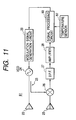
- FIG. 17 shows a schematic configuration for measuring the frequency modulation characteristic and sensing whether or not linearity is maintained in the FM-CW system radar 1 in the related art shown in FIG. 16 (a).
- Another signal source 11 is provided, the high-frequency signal from the VCO 4 is branched by a coupler 12 and is mixed by a mixer 13 for down conversion, and the difference from the frequency of the signal source 11 is counted by a counter 14. In addition to such down conversion, a method of counting the frequency of the high-frequency signal from the VCO 4 is also available.
- the FM-CW system radar 1, etc., installed in a vehicle is used in a hostile environment concerning vibration, temperature, etc.
- the linearity of the frequency modulation characteristic is good at the initial stage, there is a possibility of degradation while the radar is used.
- the down converter configuration as shown in FIG. 17 is adopted to install a configuration for detecting the linearity of the frequency modulation characteristic in the FM-CW system radar 1 itself, as the signal source 11, the mixer 13, and the like, expensive components for high frequencies of a millimeter waveband become necessary.
- the millimeter waveband cannot directly be counted and therefore a frequency divider needs to be used.
- the frequency divider operating in the millimeter waveband is expensive and as the frequency dividing ratio increases, the measurement accuracy is degraded.
- US-A-5387918 describes a frequency modulated radar apparatus with means for correction of the frequency modulation.
- a radar apparatus for performing frequency modulation of a high-frequency signal, transmitting the frequency-modulated signal, and receiving a reflected radio wave to detect a target, the radar apparatus comprising:
- the radar apparatus for performing frequency modulation of a high-frequency signal, transmitting the frequency-modulated signal, and receiving a reflected radio wave for detecting a target comprises the modulation signal generation section, the mixing section, and the signal processing section.
- the modulation signal generation section generates a modulation signal whose change state can be controlled and gives the signal to the high frequency generation section.
- the mixing section mixes the high-frequency signal generated from the high frequency generation section and the reception signal of the reflected radio wave.
- the signal processing section controls the modulation signal generation section so as to give modulation signal for detection changing between a plurality of predetermined signal levels and retained for a predetermined time for each signal level to the high frequency generation section, inputs the signal of the component of the difference between the high-frequency signal and the reception signal from the mixing section, detects the frequency, and detects the frequency modulation characteristic of the high frequency generation section based on the relationship between the signal level of the modulation signal for detection and the frequency.
- the modulation signal for detection generated from the modulation signal generation section is changed between a plurality of predetermined signal levels and is mixed with the reception signal from the target by the mixing section, the frequency of the signal of the component of the difference is detected, the relationship between the signal level of the modulation signal for detection and the frequency is found, and the frequency modulation characteristic of the high frequency generation section can be detected.
- the reception signal can be used as the high-frequency signal source to detect the frequency modulation characteristic and the mixing section for reception can also be shared, so that the frequency modulation characteristic can be detected easily in the inexpensive configuration.
- the invention provides the radar apparatus further including a modulation characteristic correction section for correcting the modulation signal based on the frequency modulation characteristic detected by the signal processing section so that the frequency modulation characteristic is not placed out of a predetermined normal range.
- the modulation signal is corrected so that the frequency modulation characteristic that can be detected easily in the inexpensive configuration is not placed out of the predetermined normal range, so that the frequency modulation characteristic can also be corrected easily in the inexpensive configuration.
- the invention provides the radar apparatus further including a width calculation section for calculating frequency modulation width, which is a difference between frequency of the differential signal when the signal level of the modulation signal is the maximum value and frequency of the differential signal when the signal level is the minimum value based on the frequency modulation characteristic detected by the signal processing section.
- the frequency modulation width of the difference between the frequency when the signal level of the modulation signal is the maximum value and the frequency when the signal level is the minimum value can be calculated based on the frequency modulation characteristic detected as frequency change between a plurality of signal levels.
- the width calculation section includes a counter for counting the frequency of the difference.
- frequency change between a plurality of signal levels is counted by the counter, so that frequency change can be measured easily.
- the invention provides the radar apparatus further including a width correction section for correcting the modulation signal based on the frequency modulation width calculated by the width calculation section so that the frequency modulation width has a predetermined value.
- the frequency modulation width of the frequency modulation characteristic can also be corrected to the predetermined value.
- a correction can also be made on the arithmetic operations.
- one of the modulation characteristic correction section and the width correction section performs the correction when the level of the reception signal of the reflected radio wave is equal to or greater than a predetermined level.
- the level of the reception signal is equal to or greater than the predetermined level, a correction is made and thus can be made stably.
- the invention provides the radar apparatus further including further comprising a temperature detection section, in which one of the modulation characteristic correction section and the width correction section performs the correction when a temperature detected by the temperature detection section has a predetermined temperature.
- the frequency of the high-frequency signal generated from the high frequency generation section changes with the temperature
- a correction is made if the predetermined temperature of the temperature detection section is reached, so that the effect of the temperature can be decreased and the accuracy of the frequency modulation characteristic can be enhanced.
- one of the modulation characteristic correction section and the width correction section performs the correction when a distance to the target is in a predetermined distance range.
- the distance range, etc., having a high possibility that the signal level of the reception signal will lower is placed out of the predetermined distance range, whereby correction processing is not entered, so that accuracy degradation of correction can be avoided.
- one of the modulation characteristic correction section and the width correction section performs the correction when relative speed of the target is in a predetermined speed range.
- the relative speed of the target is considered and if the relative speed of the target is placed in the predetermined speed range, a correction is made, so that the accuracy of the correction can be enhanced.
- the signal processing section detects the frequency modulation characteristic when an input level of the reflected radio wave from the target is equal to or greater than a predetermined reference level at a normal radar operation time.
- the frequency modulation characteristic is detected, so that the radar apparatus can concentrate attention on usual target detection processing.
- the signal processing section detects the frequency modulation characteristic when a distance to the target is in a predetermined distance range.
- the frequency modulation characteristic is not detected, so that the radar apparatus can concentrate attention on usual target detection processing.
- the signal processing section detects the frequency modulation characteristic just after detecting the target initially after a radar operation starts and determines whether or.not a normal modulation operation for the high frequency generation section is performed.
- the target is detected initially and it is made possible to receive the reflected radio wave, whether or not the frequency modulation characteristic of the high frequency modulation section is normal is determined, so that occurrence of an anomaly can be found at an early stage if the anomaly occurs.
- the invention provides the radar apparatus further including a reference signal source for generating a reference signal to decrease a frequency with respect to the differential signal between the high-frequency signal and the reception signal, the differential signal inputted to the signal processing section from the mixing section, in which the signal processing section detects the frequency modulation characteristic based on the inputted differential signal with the frequency decreased by the reference signal.
- the reference signal generated from the reference signal source is heterodyned and the frequency is decreased, so that frequency measurement is facilitated.
- the reference signal source includes a basic signal generation section for generating a basic signal, which is a source of the reference signal, and a frequency division section for dividing the frequency of the basic signal generated from the basic signal generation section according to one of frequency dividing ratios that can be switched to convert the basic signal into the reference signal.
- the frequency dividing ratio of the frequency division section is changed for switching the frequency of the reference signal provided by dividing the frequency of the basic signal generated from the basic signal generation section, the frequency is lowered, and the frequency measurement accuracy can be enhanced.
- the reference signal source includes a plurality of reference signal generation sections and selects one of the reference signal generation sections to generate the reference signal.
- a plurality of reference signal generation section are switched for generating the reference signal and the signal components provided by switching the reference signal generation section are compared, whereby it is made possible to determine the frequency to be measured, and the accuracy can be enhanced.
- the reference signal source comprises a signal arithmetic section for generating the reference signal by performing arithmetic processing according to a preset program.
- the reference signal of the frequency fitted for frequency measurement can be generated for enhancing the measurement accuracy.
- the reference signal source supplies a clock signal for a signal arithmetic processing to the signal processing section.
- generation of the reference signal and clock signal supply to the signal processing section can be conducted from the common reference signal source, so that space saving and cost reduction are made possible.
- a frequency of the reference signal is set so that a difference from the frequency of the reception signal from the target is within a beat signal band at a time of a radar operation.
- the reference signal set within the beat signal band is used, so that the band of the frequency of the difference provided by heterodyning can be lowered for enhancing the measurement accuracy.
- the signal processing section performs at least a part of processing of the beat signal.
- the configuration is shared between at least a part of beat signal processing and a part of detection processing of the frequency modulation characteristic, so that the whole configuration can be simplified and can be implemented at low costs.
- the signal processing section changes a predetermined time for holding a signal level of the modulation signal for detection in response to a distance to the target.
- frequency modulation characteristic detection can be optimized in response to the distance to the target and the detection accuracy can be enhanced.
- the signal processing section changes a predetermined time for holding a signal level of the modulation signal for detection in response to a relative speed of the target.
- the detection accuracy.of the frequency modulation characteristic can be enhanced considering the relative speed with the target
- the signal processing section detects the frequency of the differential signal between the high-frequency signal and the reception signal considering a Doppler shift based on a relative speed of the target.
- the frequency modulation characteristic can be detected with good accuracy considering the Doppler shift.
- FIG. 1 (a) shows a schematic electric configuration of an FM-CW system radar 21 of a first embodiment of the invention
- FIG. 1 (b) shows the waveform of a modulation signal
- FIG. 1 (c) shows the waveform of a modulation signal for detection.
- the FM-CW system radar 21 of the embodiment has a basic configuration similar to that of the FM-CW system radar 1 in the related art shown in FIG. 16 (a). That is, it includes a transmission antenna 22, a reception antenna 23, a VCO 24, a coupler 25, a mixer 26, a BPF 27, an amplifier 28, a modulation signal generation circuit 29, and a signal processing circuit 30.
- a radio wave is transmitted from the transmission antenna 22 and the reflected radio wave from a target, etc., is received at the reception antenna 23.
- a high-frequency signal of a millimeter waveband generated from the VCO (voltage-controlled oscillator) 24 is given to the transmission antenna 22.
- a part of the high-frequency signal for exciting the transmission antenna 22 from the VCO 24 branches from the coupler 25 and is mixed with a reception signal from the reception antenna 23 by the mixer 26.
- a beat signal in an output signal from the mixer 26 is selected through the BPF (band-pass filter) 27 and is amplified by the amplifier 28.
- the high-frequency signal generated from the VCO 24 is subjected to frequency modulation in accordance with the voltage level of a modulation signal given by the modulation signal generation circuit 29.
- the beat signal is processed by the signal processing circuit 30 for calculating the distance to the target and the relative speed.
- a modulation signal shaped like a triangular wave of several hundred Hz as shown in FIG. 1 (b) is used to generate an FM wave with the maximum frequency shift amount being several ten to several hundred MHz.
- a saw tooth wave may be used in some cases.
- the normal operation of the FM-CW system radar 21 is similar to that of the FM-CW system radar 1 in the related art shown in FIG. 16.
- a modulation signal for detection shaped like a rectangular wave changing at voltage V1 as shown in FIG. 1 (c) is given to the VCO 24 from the modulation signal generation circuit 29. Therefore, it is made possible to sense whether or not the frequency modulation characteristic of the VCO 24 has good linearity relative to change in the voltage level of the modulation signal.
- FIGS. 2 (a) to 2 (c) show the principle to provide the shift component of frequency modulation corresponding to the modulation signal for detection shaped like a rectangular wave shown in FIG. 1 (c).
- frequency shift component ⁇ F is provided in response to change in voltage V1 as in FIG. 1 (c).
- a signal waveform as shown in FIG. 2 (a) is provided and is almost the same as the waveform transmitted from the transmission antenna 22.
- the phase is delayed as shown in FIG. 2 (b) based on the propagation delay of the radio wave.
- a beat signal of frequency of ⁇ F is provided only for the time period of the propagation delay. If the relative speed to the target is not zero, a Doppler shift component is also contained, but is about several kHz. Since the frequency ⁇ F of the beat signal is several MHz to several 10 MHz, the effect of the Doppler shift component is small.
- FIG. 3 shows an example of the frequency modulation characteristic in the VCO 24 in FIG. 1 (a).
- the frequency shift amount between the minimum value V1 of the lower limit voltage of the modulation signal and the maximum value V2 of the upper limit voltage is found by adding up frequency shift ⁇ fn corresponding to section voltage ⁇ Vn.
- As a method of changing the voltage level between V1 and V2 to provide the modulation signal for detection it is possible to change the voltage level (modulation signal for detection) stepwise as shown in FIG. 4 and it is possible to change the pulse-like peak value as shown in FIG. 5.
- FIG. 4 (a) shows the waveform of the modulation signal for detection changing stepwise and FIG. 4 (b) shows the frequency shift of the beat signal.
- FIG. 5 (a) shows the waveform of the modulation signal for detection changing like a pulse and FIG. 5 (b) shows the frequency shift of the beat signal.
- the modulation width is found by adding up the frequency shift components as shown in expression (1) given below.
- the last frequency shift component shown in FIG. 5 (b) is the added-up value.
- the FM-CW system radar apparatus 21 in which a modulation signal shaped like a triangular wave is given to the VCO 24 of a high-frequency generation section to generate a high-frequency signal whose frequency changes and a radio wave is transmitted from the transmission antenna 22 based on the generated high-frequency signal and the reflected radio wave is received for detecting the target.
- the radar apparatus 21 includes the modulation signal generation circuit 29 of a modulation signal generation section, the mixer 26 of a mixing section, and the signal processing circuit 30 of a signal processing section.
- the modulation signal generation circuit 29 generates a modulation signal for detection whose change state can be controlled and gives the modulation signal to the VCO 24.
- the mixer 26 mixes the high-frequency signal generated from the VCO 24 and the reception signal of the reflected radio wave.
- the signal processing circuit 30 controls the modulation signal generation circuit 29 so as to give the modulation signal for detection changing among a plurality of predetermined signal levels and retained for a predetermined time for each signal level to the VCO 24, as shown in FIG. 4 (a), 5 (a).
- the signal processing circuit 30 inputs the signal of the component of the difference between the high-frequency signal and the reception signal from the mixer 26 to detect the frequency, and detects the frequency modulation characteristic of the VCO 24 based on the relationship between the signal level of the modulation signal for detection and the frequency.
- the reception signal is used as the high-frequency signal source for frequency characteristic detection and the mixer 26 for reception can also be shared, so that the frequency modulation characteristic can be detected easily in the inexpensive configuration.
- FIG. 6 shows a schematic electric configuration of an FM-CW system radar 31 of a second embodiment of the invention.
- a modulation signal correction circuit 32 corrects a modulation signal of a triangular wave, etc., generated by a modulation signal generation circuit 29 and gives the corrected modulation signal to a VCO 24.
- the modulation signal correction circuit 32 corrects the modulation signal in accordance with a correction signal given by a signal processing circuit 40.
- the signal processing circuit 40 generates the correction signal so that the frequency modulation characteristic detected in a similar manner to that in the first embodiment is not placed out of a predetermined normal range. For the frequency modulation characteristic, the linearity indicating the linearity range and the modulation width indicating the upper and lower limits are corrected.
- a polygonal line circuit can be used.
- a gain control amplifier can be used.
- the modulation signal correction circuit 32 serves as a range correction section if it makes a linearity correction; the modulation signal correction circuit 32 serves as modulation characteristic correction section if it corrects the modulation width.
- FIG. 7 shows a schematic electric configuration of an FM-CW system radar 41 of a third embodiment of the invention.
- a modulation signal generation circuit 49 includes a D/A converter 42 for converting a digital signal representing modulation data given by a signal processing circuit 50 into an analog signal to generate a modulation signal.
- the signal processing circuit 50 detects the frequency modulation characteristic in a similar manner to that in the first embodiment and stores modulation data for correcting the detected characteristic in an internal memory 51.
- the memory 51 serves as a range correction section and a modulation width correction section.
- the modulation signal is corrected so that the frequency modulation characteristic that can be detected easily in the inexpensive configuration is not placed out of a predetermined normal range and thus the frequency modulation characteristic can also be corrected easily in the inexpensive configuration.
- FIG. 8 shows a partial electric configuration of an FM-CW system radar 61 of a fourth embodiment of the invention.
- a beat signal output from an amplifier 28 is converted into a digital signal by an A/D converter 62 and signal level is obtained by a DSP (digital signal processor) 64 and FFT proces sing 63 by a microcomputer.
- the FFT processing 63 which is fast Fourier transform processing, is implemented as the program operation of the DSP 64, etc.
- a signal processing circuit 70 of the embodiment includes the A/D converter 62 and the DSP 64.
- the signal level of the beat signal can be determined as to any reference level.
- FIG. 9 shows a partial electric configuration of an FM-CW system radar 71 of a fifth embodiment of the invention.
- a beat signal is detected by a detection circuit 74 and is compared with a reference signal by a comparator 75 for determining signal level.
- the beat signal is converted into a digital signal by an A/D converter 72 and arithmetic processing is performed by a microcomputer 73, a DSP, etc.
- a signal processing circuit 80 of the embodiment includes the A/D converter 72 and the microcomputer 73.
- FIG. 10 shows a processing procedure of detecting the frequency modulation characteristic in response to the signal level of a reception signal in the fourth and fifth embodiments previously described with reference to FIGS. 8 and 9.
- the procedure is started at step a0.
- the beat signal level is calculated as the usual FM-CW radar.
- step a2 whether or not the beat signal level is greater than a setup reference level is determined. If it is determined that the beat signal level is greater than the setup level, whether or not the frequency modulation characteristic is to be detected is determined at step a3.
- the frequency modulation characteristic may be detected, for example, for the first detected target after the power is turned on, and need not always be detected.
- step a3 If it is determined at step a3 that the frequency modulation characteristic is to be detected, detection processing of the frequency modulation characteristic is performed at step a4 in a similar manner to that in the first embodiment. At a5, whether or not the detection result involves a problem is determined. If the detection result involves a problem, at step a6, correction processing is performed as in the second or third embodiment or warning processing with an alarm, etc., is performed. If it is not determined at step a2 that the beat signal level is greater than the setup level, if it is not determined at step a3 that the frequency modulation characteristic is to be detected, or if it is not determined at step a5 that the detection result involves a problem, normal FM-CW radar : processing is performed at step a7. When the input level of the reception signal is equal to or greater than the predetermined reference level, a correction is made and thus can be made stably.
- occurrence of an anomaly can also be found at an early stage by determining whether or not the frequency modulation characteristic of the VCO 24 is normal.
- FIG. 11 shows a schematic electric configuration of an FM-CW system radar 81 of a sixth embodiment of the invention.
- the temperature in the proximity, etc., of a VCO 24 is detected by a temperature sensor 82 such as a thermister and if the frequency modulation characteristic of the VCO 24 changes with the temperature, it is also made possible to make a correction for each arbitrary temperature and the accuracy of the frequency modulation characteristic can be enhanced.
- the temperature detected by the temperature sensor 82 is given to a signal processing circuit 90 and a correction can be made in a similar manner to that in the embodiments previously described with reference to FIGs. 6, 7.
- a correction can also be made if the temperature detected by the temperature sensor 82 as a temperature detection section becomes a predetermined temperature.
- the frequency modulation characteristic is detected and corrected and/or if the relative speed of the target is in the predetermined speed range, the frequency modulation characteristic is detected and corrected.
- the distance range, etc. having a high possibility that the signal level of the reception signal will lower is placed out of the predetermined distance range, whereby detection processing and correction processing are not entered at such a distance, so that accuracy degradation of detection and correction can be avoided.
- the relative speed the relative speed of the target is considered and if the relative speed of the target is.placed in the predetermined speed range, detection and correction are executed, so that the accuracy can be enhanced.
- FIG. 12 shows a partial electric configuration of a signal processing circuit 100 of an FM-CW system radar of a seventh embodiment of the invention.
- a beat signal is converted into a digital signal by an A/D converter 102 and the digital signal is input to a microcomputer 103 in a similar manner to that in the embodiment previously described with reference to FIG. 9, and the frequency count result of a frequency counter 104 is input to the microcomputer 103. Since the frequency counter 104 is used, frequency measurement of the beat signal can be conducted easily.
- FIG. 13 shows a schematic electric configuration of an FM-CW system radar 111 of an eighth embodiment of the invention.
- a beat signal of the FM-CW system radar is mixed with a reference signal generated from a signal source 112 by a mixer 113 for heterodyning and further the frequency can be lowered for facilitating frequency measurement.
- An output of the mixer 113 is selected through a BPF 114 and is amplified by an amplifier 115 and is fed into a signal processing circuit 120.
- the signal processing circuit 120 detects and corrects the frequency modulation characteristic in a similar manner to that in each embodiment described above.
- FIG. 14 shows an example of implementing the signal source 112 in the embodiment in FIG. 13.
- a changeover switch 114 a frequency divider 115', and an oscillator 116 are included.
- the oscillator 116 becomes a basic signal generation section for.generating a basic signal as a source of the reference signal.
- the frequency divider 115' becomes a frequency division section for dividing the frequency of the basic signal according to one of frequency dividing ratios that can be switched by the changeover switch 114 for converting the basic signal into the reference signal.
- outputs of a plurality of oscillators 117, 118, and 119 are switched by the changeover switch 114.
- the signal processing circuit 120 directly generates the reference signal by performing program processing and feeds the signal into the mixer 113.
- the reference signal and a clock signal based on which the signal processing circuit 120 operates can be generated in common.
- the frequency measurement accuracy can be enhanced.
- the frequency dividing ratio is changed for switching the frequency of the reference signal provided by dividing the frequency of the basic signal generated from the basic signal generation section, the frequency measurement accuracy can be enhanced.
- the oscillator 117, 118, or 119 is selected for generating the reference signal, it is made possible to determine the frequency to be measured, and the accuracy can be enhanced.
- the reference signal is generated by performing arithmetic processing following the preset program, the reference signal of the frequency being suitable for frequency measurement can be generated to enhance the measurement accuracy. If the reference signal and the clock signal of the signal processing circuit 120 are used as a common signal, the need for providing new signal source 113 is eliminated and space saving and cost reduction are made possible.
- the frequency of the reference signal is set so that the difference from the frequency of the reception signal from the target becomes within the beat signal band at the radar operation time. Since the reference signal set within the beat signal band is used, the band of the frequency of the difference provided by heterodyning can be lowered for enhancing the measurement accuracy.
- the signal processing circuit 120 performs at least a part of beat signal processing in the FM-CW system radar. Since the configuration is shared between at least a part of beat signal processing and a part of detection processing of the frequency modulation characteristic, the whole configuration is simplified and can be implemented at low costs.
- FIG. 15 shows a schematic electric configuration of an FM-CW system radar 121 of a ninth embodiment of the invention.
- the concept disclosed as the second embodiment in JP-A-5-40169 can be applied for enhancing the S/N ratio of a reception signal.
- a beat signal is converted into a digital signal by an A/D converter 122 and FFT processing 123 is performed by a DSP 124, etc.
- a modulation signal is fed into a gate switch 126 from a signal source 125 for performing frequency modulation of a reception signal. Then, the beat signal is provided by a mixer 26 and further is mixed with the modulation signal by a mixer 127 and the resultant signal is detected.
- a signal processing circuit 130 of the embodiment includes the A/D converter 122 and the DSP 124.
- the time (t1, t2, t3, ..., tn) taken for holding the voltage level in a plurality of values in the range of V1 to V2 in the modulation signal for detection shown in FIGS. 4 (a) and 5 (b) is changed in response to the distance to the target and the relative speed. Accordingly, frequency modulation characteristic detection can be optimized in response to the distance to the target and the relative speed and the detection accuracy can be enhanced.
- the signal processing circuit in each embodiment detects the frequency of the beat signal component of the difference between the high-frequency signal and the reception signal considering the Doppler shift based on the relative speed of the target. If it is difficult to find out a relatively still object when the radar is installed in an automobile, etc., the frequency modulation characteristic can be detected with good accuracy considering the Doppler shift.
- the FM-CW system radars have been described, but the invention can also be applicable to other types of radar.
- the reception signal from the target can be used to detect the frequency modulation characteristic of the high frequency generation section.
- the reception signal can be used as the high-frequency signal source to detect the frequency modulation characteristic and the mixing section for reception can also be shared, so that the frequency modulation characteristic can be detected easily in the inexpensive configuration.
- the modulation signal is corrected so that the frequency modulation characteristic is not placed out of the predetermined normal range, so that the frequency modulation characteristic can be corrected easily in the inexpensive configuration.
- the frequency modulation width can be calculated from frequency change between a plurality of signal levels.
- the frequency change can be counted. by the counter, so that frequency change can be measured easily.
- the frequency modulation width of the frequency modulation characteristic can be corrected to the predetermined value.
- the level of the reception signal is equal to or greater than the predetermined level, a stable correction can be made.
- the effect of the temperature can be decreased and the accuracy of the frequency modulation characteristic can be enhanced.
- the relative speed of the target is considered and the accuracy of the correction can be enhanced.
- the radar apparatus can concentrate attention on usual target detection processing. Whether or not detection processing of the frequency modulation characteristic is to be performed is determined based on the signal level at the usual radar operation time, so that the number of detection processing times can be decreased.
- the radar apparatus can concentrate attention on usual target detection processing.
- the reference signal generated from the reference signal source is heterodyned and the frequency is decreased, so that frequency measurement of the beat signal is facilitated.
- a plurality of frequency dividing ratios can be switched for lowering the frequency, and the frequency measurement accuracy can be enhanced.
- a plurality of reference signals are switched and the signal components provided by switching the reference signals are compared, whereby it is made possible to determine the frequency to be measured, and the accuracy can be enhanced.
- the reference signal of the frequency fitted for frequency measurement can be generated for enhancing the measurement accuracy.
- the reference signal set within the beat signal band is used and the measurement accuracy can be enhanced.
- the configuration can be shared between at least a part of beat signal processing and a part of detection processing of the frequency modulation characteristic, the whole configuration can be simplified, the costs can be reduced.
- Frequency modulation characteristic detection can be optimized in response to the distance to the target and the detection accuracy can be enhanced.
- the detection accuracy of the frequency modulation characteristic can be enhanced considering the relative speed with the target.
- the frequency modulation characteristic can be detected with good accuracy considering the Doppler shift.
Landscapes
- Engineering & Computer Science (AREA)
- Radar, Positioning & Navigation (AREA)
- Remote Sensing (AREA)
- Computer Networks & Wireless Communication (AREA)
- Physics & Mathematics (AREA)
- General Physics & Mathematics (AREA)
- Signal Processing (AREA)
- Radar Systems Or Details Thereof (AREA)
Applications Claiming Priority (2)
| Application Number | Priority Date | Filing Date | Title |
|---|---|---|---|
| JP2001211314A JP2003028951A (ja) | 2001-07-11 | 2001-07-11 | レーダ装置 |
| JP2001211314 | 2001-07-11 |
Publications (3)
| Publication Number | Publication Date |
|---|---|
| EP1275979A2 EP1275979A2 (en) | 2003-01-15 |
| EP1275979A3 EP1275979A3 (en) | 2003-08-13 |
| EP1275979B1 true EP1275979B1 (en) | 2006-10-04 |
Family
ID=19046650
Family Applications (1)
| Application Number | Title | Priority Date | Filing Date |
|---|---|---|---|
| EP02254851A Expired - Fee Related EP1275979B1 (en) | 2001-07-11 | 2002-07-10 | Radar apparatus |
Country Status (6)
| Country | Link |
|---|---|
| US (2) | US6597308B2 (ja) |
| EP (1) | EP1275979B1 (ja) |
| JP (1) | JP2003028951A (ja) |
| KR (1) | KR100487756B1 (ja) |
| CN (1) | CN1252491C (ja) |
| DE (1) | DE60215078T2 (ja) |
Cited By (1)
| Publication number | Priority date | Publication date | Assignee | Title |
|---|---|---|---|---|
| CN102928834A (zh) * | 2012-11-23 | 2013-02-13 | 北京理工大学 | 一种基于无相位突变拼接信号的调频连续波测距方法 |
Families Citing this family (47)
| Publication number | Priority date | Publication date | Assignee | Title |
|---|---|---|---|---|
| JP2003028951A (ja) * | 2001-07-11 | 2003-01-29 | Fujitsu Ten Ltd | レーダ装置 |
| JP3633597B2 (ja) * | 2002-09-30 | 2005-03-30 | 三菱電機株式会社 | パルスレーダ装置 |
| CA2448479C (en) * | 2002-11-12 | 2009-05-05 | Makita Corporation | Power tools |
| JP4204358B2 (ja) * | 2003-03-20 | 2009-01-07 | 富士通テン株式会社 | 送受信共用fm−cwレーダ装置及びその信号処理方法 |
| JP2004361245A (ja) * | 2003-06-04 | 2004-12-24 | Fujitsu Ten Ltd | レーダ装置 |
| JP4209312B2 (ja) * | 2003-11-28 | 2009-01-14 | 三菱電機株式会社 | 周波数変調レーダ装置 |
| JP2005180992A (ja) * | 2003-12-17 | 2005-07-07 | Tdk Corp | レーダ装置 |
| DE602005010679D1 (de) * | 2004-03-15 | 2008-12-11 | Kongsberg Seatex As | Verfahren und system zur bestimmung der position von seefahrzeugen und anderen objekten |
| JP4420743B2 (ja) * | 2004-05-31 | 2010-02-24 | 富士通テン株式会社 | Fm−cwレーダ装置 |
| JP2006003303A (ja) * | 2004-06-21 | 2006-01-05 | Fujitsu Ten Ltd | レーダ装置 |
| US7439905B2 (en) * | 2004-09-13 | 2008-10-21 | Fujitsu Ten Limited | Radar apparatus |
| JP2007051888A (ja) * | 2005-08-16 | 2007-03-01 | Mitsubishi Electric Corp | レーダ装置 |
| JP4855749B2 (ja) * | 2005-09-30 | 2012-01-18 | 株式会社トプコン | 距離測定装置 |
| US7705773B2 (en) * | 2005-12-19 | 2010-04-27 | Honeywell International Inc. | Self-calibrating a radar altimeter based on a simulated return signal |
| US7345619B2 (en) * | 2005-12-30 | 2008-03-18 | Valeo Raytheon Systems, Inc. | Generating event signals in a radar system |
| JP4684112B2 (ja) * | 2006-01-31 | 2011-05-18 | 富士通テン株式会社 | 三角波生成回路 |
| JP4407769B2 (ja) * | 2006-12-11 | 2010-02-03 | 株式会社村田製作所 | レーダ装置 |
| DE102006061670A1 (de) * | 2006-12-28 | 2008-07-03 | Robert Bosch Gmbh | Verfahren zum Betreiben eines Radars und ein Radar |
| FR2913775B1 (fr) * | 2007-03-16 | 2010-08-13 | Thales Sa | Systeme de detection d'obstacle notamment pour un systeme d'anticollision |
| JP4689754B2 (ja) | 2007-08-28 | 2011-05-25 | 富士通株式会社 | 位相同期発振器及びそれを備えたレーダ装置 |
| US7612707B2 (en) * | 2007-09-28 | 2009-11-03 | Banner Engineering Corporation | Configurable radar sensor |
| KR101007157B1 (ko) * | 2007-10-05 | 2011-01-12 | 주식회사 에이스테크놀로지 | 방사 패턴의 방향을 제어하는 안테나 |
| US7656750B2 (en) * | 2008-02-26 | 2010-02-02 | Semiconductor Components Industries, Llc | Echo detection |
| JP5319145B2 (ja) * | 2008-03-25 | 2013-10-16 | 株式会社東芝 | レーダー装置、レーダー装置の制御方法 |
| JP2010008273A (ja) * | 2008-06-27 | 2010-01-14 | Maspro Denkoh Corp | ミリ波撮像装置 |
| JP2010204003A (ja) | 2009-03-05 | 2010-09-16 | Hitachi Kokusai Electric Inc | 複合機能レーダ装置 |
| JP2011130174A (ja) * | 2009-12-17 | 2011-06-30 | Fujitsu Ltd | 通信装置 |
| CN101793964A (zh) * | 2010-03-09 | 2010-08-04 | 浙江大学 | 带有数字化温度补偿的60GHz毫米波汽车防撞雷达装置 |
| JP5436332B2 (ja) * | 2010-05-21 | 2014-03-05 | 三菱電機株式会社 | Fmcwレーダ装置の周波数変調回路 |
| JP5350328B2 (ja) * | 2010-06-10 | 2013-11-27 | 株式会社京三製作所 | 距離センサ及び制御方法 |
| JP5350331B2 (ja) * | 2010-06-15 | 2013-11-27 | 株式会社京三製作所 | 距離センサ |
| CN101950021A (zh) * | 2010-08-24 | 2011-01-19 | 浙江大学 | 超声波与毫米波联合测量的无盲区汽车防撞雷达装置 |
| JP5018943B2 (ja) * | 2010-09-07 | 2012-09-05 | 株式会社デンソー | レーダ装置 |
| DE102010061041A1 (de) * | 2010-12-06 | 2012-06-06 | Hella Kgaa Hueck & Co. | Vorrichtung mit einem spannungsgesteuerten Oszillator und Mitteln zur Eigenkalibrierung |
| CN102508233A (zh) * | 2011-10-08 | 2012-06-20 | 天津理工大学 | 一种采用电流源法实现时间-电压转换的雷达测距系统 |
| EP2660568A1 (de) * | 2012-05-03 | 2013-11-06 | VEGA Grieshaber KG | Fehlerkompensation durch Vermessen der STC-Filterfunktion |
| EP2901178A4 (en) * | 2012-09-27 | 2016-03-30 | Honeywell Int Inc | SYSTEMS AND METHOD FOR USING A RADAR-ADAPTIVE RADIATION PATTERN FOR WING-TIP PROTECTION |
| US9341509B2 (en) * | 2013-08-05 | 2016-05-17 | Finetek Co., Ltd. | Frequency modulation continuous wave radar level meter and signal-tracking and phase-locking method for the same |
| US10001548B2 (en) * | 2015-01-23 | 2018-06-19 | Navico Holding As | Amplitude envelope correction |
| EP3059559A1 (en) | 2015-02-23 | 2016-08-24 | Siemens Aktiengesellschaft | FMCW radar system |
| KR101760907B1 (ko) * | 2015-11-20 | 2017-07-24 | 주식회사 만도 | 차량용 레이더 장치 및 그의 타겟 측정 방법 |
| US10411716B2 (en) * | 2016-06-06 | 2019-09-10 | Richwave Technology Corp. | Subsampling motion detector for detecting motion of object under measurement |
| CN106443601A (zh) * | 2016-08-31 | 2017-02-22 | 贵州航天电子科技有限公司 | 一种等效无线电探测设备距离启动试验方法 |
| CN108226876A (zh) * | 2017-12-28 | 2018-06-29 | 北京融创远大网络科技有限公司 | 一种降低极化损耗的智能车载雷达装置 |
| DE102018203465A1 (de) | 2018-03-08 | 2019-09-12 | Robert Bosch Gmbh | Radarsensorsystem und Verfahren zum Betreiben eines Radarsensorsystems |
| CN111239638B (zh) * | 2020-01-10 | 2022-02-11 | 天津天传电控设备检测有限公司 | 一种交流电压源输出频率周期性和随机性变化的检测方法 |
| US11356104B2 (en) * | 2020-07-01 | 2022-06-07 | Jvckenwood Corporation | Phase locked loop circuit |
Family Cites Families (21)
| Publication number | Priority date | Publication date | Assignee | Title |
|---|---|---|---|---|
| JPS49107491A (ja) * | 1973-02-15 | 1974-10-12 | ||
| US4008475A (en) * | 1975-11-12 | 1977-02-15 | Rca Corporation | Stabilizing and calibration circuit for FM-CW radar ranging systems |
| US4348675A (en) * | 1979-05-23 | 1982-09-07 | Honda Giken Kogyo Kabushiki Kaisha | FM-CW Radar system for use in an automotive vehicle |
| US5172123A (en) * | 1985-01-29 | 1992-12-15 | Hercules Defense Electronics, Inc. | Frequency feedback linearizer |
| US4692766A (en) * | 1985-09-25 | 1987-09-08 | Rolfs John C | Linearizer frequency discriminator for frequency modulated radar transmitters |
| US5210539A (en) * | 1986-09-30 | 1993-05-11 | The Boeing Company | Linear frequency sweep synthesizer |
| JPS6396583A (ja) * | 1986-10-14 | 1988-04-27 | Mitsubishi Electric Corp | マイクロ波レベル計 |
| JP2665834B2 (ja) * | 1991-02-15 | 1997-10-22 | 本田技研工業株式会社 | Fmレーダ |
| JP2583723B2 (ja) * | 1991-04-18 | 1997-02-19 | エンドレス ウント ハウザー ゲゼルシヤフト ミツト ベシユレンクテル ハフツング ウント コンパニー | 反射ビーム方式による間隔距離測定のための方法及び装置 |
| JP2981312B2 (ja) | 1991-08-08 | 1999-11-22 | 富士通株式会社 | Fm−cwレーダ装置 |
| JP2657020B2 (ja) * | 1992-03-17 | 1997-09-24 | 富士通株式会社 | Fm−cwレーダ装置 |
| FR2691809B1 (fr) * | 1992-05-26 | 1994-09-02 | Thomson Csf | Procédé de compensation automatique de la non linéarité de la pente de modulation d'un radar à onde continue modulée en fréquence et radar pour sa mise en Óoeuvre. |
| JPH0755924A (ja) | 1993-08-11 | 1995-03-03 | Daikin Ind Ltd | Fmcwレーダの送信波生成方法およびfmcwレーダ |
| GB2291551B (en) * | 1994-06-24 | 1998-03-18 | Roscoe C Williams Limited | Electronic viewing aid |
| JP3485382B2 (ja) | 1995-06-01 | 2004-01-13 | 富士通テン株式会社 | Fm−cwレーダ装置 |
| US5642081A (en) * | 1995-10-26 | 1997-06-24 | Alliant Techsystems Inc. | FMCW VCO closed loop linearizer |
| US5719580A (en) * | 1996-06-06 | 1998-02-17 | Trw Inc. | Method and apparatus for digital compensation of VCO nonlinearity in a radar system |
| JP3562408B2 (ja) * | 1999-11-10 | 2004-09-08 | 株式会社デンソー | レーダ装置特性検出装置及び記録媒体 |
| JP3489514B2 (ja) * | 1999-12-09 | 2004-01-19 | 株式会社デンソー | Fmcwレーダ装置 |
| DE10018553A1 (de) * | 2000-04-14 | 2001-10-18 | Bosch Gmbh Robert | Verfahren zur Erfassung und Korrektur von Nichtlinearitäten in einem Mikrowellenradarsystem |
| JP2003028951A (ja) * | 2001-07-11 | 2003-01-29 | Fujitsu Ten Ltd | レーダ装置 |
-
2001
- 2001-07-11 JP JP2001211314A patent/JP2003028951A/ja active Pending
-
2002
- 2002-07-10 DE DE60215078T patent/DE60215078T2/de not_active Expired - Lifetime
- 2002-07-10 EP EP02254851A patent/EP1275979B1/en not_active Expired - Fee Related
- 2002-07-10 KR KR10-2002-0039965A patent/KR100487756B1/ko not_active IP Right Cessation
- 2002-07-11 US US10/192,520 patent/US6597308B2/en not_active Expired - Lifetime
- 2002-07-11 CN CNB021410321A patent/CN1252491C/zh not_active Expired - Fee Related
-
2003
- 2003-07-18 US US10/621,617 patent/US20050007271A1/en not_active Abandoned
Cited By (1)
| Publication number | Priority date | Publication date | Assignee | Title |
|---|---|---|---|---|
| CN102928834A (zh) * | 2012-11-23 | 2013-02-13 | 北京理工大学 | 一种基于无相位突变拼接信号的调频连续波测距方法 |
Also Published As
| Publication number | Publication date |
|---|---|
| DE60215078D1 (de) | 2006-11-16 |
| US6597308B2 (en) | 2003-07-22 |
| JP2003028951A (ja) | 2003-01-29 |
| EP1275979A2 (en) | 2003-01-15 |
| DE60215078T2 (de) | 2007-05-03 |
| EP1275979A3 (en) | 2003-08-13 |
| KR100487756B1 (ko) | 2005-05-06 |
| CN1396464A (zh) | 2003-02-12 |
| US20030016163A1 (en) | 2003-01-23 |
| CN1252491C (zh) | 2006-04-19 |
| KR20030007099A (ko) | 2003-01-23 |
| US20050007271A1 (en) | 2005-01-13 |
Similar Documents
| Publication | Publication Date | Title |
|---|---|---|
| EP1275979B1 (en) | Radar apparatus | |
| US20190004167A1 (en) | Range Resolution in FMCW Radars | |
| US6040796A (en) | Radar system installable in an automotive vehicle for detecting a target object | |
| US7187321B2 (en) | Interference determination method and FMCW radar using the same | |
| US7148840B2 (en) | Radar apparatus, radar apparatus controlling method | |
| US7095362B2 (en) | Radar measurement device, especially for a motor vehicle, and method for operating a radar measurement device | |
| US6384768B1 (en) | FM pulse Doppler radar apparatus | |
| US20180011181A1 (en) | Radar systems and methods thereof | |
| US20030052813A1 (en) | Radar designed to minimize error in detecting target | |
| US7397420B2 (en) | Timing adjustment method for radar, and radar apparatus having automatic timing adjusting function | |
| JP2005049310A (ja) | 車両用レーダ装置および当該レーダ装置の車両への装着角度調整方法 | |
| JP5097467B2 (ja) | 車載用レーダ装置 | |
| JP4032881B2 (ja) | Fm−cwレーダ装置 | |
| US20050168377A1 (en) | On-vehicle radar system | |
| US20030151543A1 (en) | Radar system and method of adjusting characteristics thereof | |
| EP1635192A1 (en) | Radar apparatus with DC offset correction | |
| US6087979A (en) | Rangefinder | |
| JP2003043137A (ja) | Fmcwレーダ装置 | |
| JP7123571B2 (ja) | Fmcwレーダ装置 | |
| JP2004245647A (ja) | 近距離レーダ装置および近距離レーダ装置を搭載した車両 | |
| WO2011136281A1 (ja) | 車載用レーダ装置及び車載用レーダシステム | |
| JP3565646B2 (ja) | Fm−cwレーダ | |
| JPH0755925A (ja) | Fmcwレーダの距離補正方法およびfmcwレーダ | |
| JP2004264234A (ja) | レーダ装置 | |
| JP4225804B2 (ja) | レーダ装置 |
Legal Events
| Date | Code | Title | Description |
|---|---|---|---|
| PUAI | Public reference made under article 153(3) epc to a published international application that has entered the european phase |
Free format text: ORIGINAL CODE: 0009012 |
|
| AK | Designated contracting states |
Kind code of ref document: A2 Designated state(s): AT BE BG CH CY CZ DE DK EE ES FI FR GB GR IE IT LI LU MC NL PT SE SK TR |
|
| AX | Request for extension of the european patent |
Free format text: AL;LT;LV;MK;RO;SI |
|
| PUAL | Search report despatched |
Free format text: ORIGINAL CODE: 0009013 |
|
| AK | Designated contracting states |
Designated state(s): AT BE BG CH CY CZ DE DK EE ES FI FR GB GR IE IT LI LU MC NL PT SE SK TR |
|
| AX | Request for extension of the european patent |
Extension state: AL LT LV MK RO SI |
|
| RIC1 | Information provided on ipc code assigned before grant |
Ipc: 7G 01S 13/34 A Ipc: 7G 01S 7/35 B Ipc: 7G 01S 7/40 B |
|
| 17P | Request for examination filed |
Effective date: 20040203 |
|
| AKX | Designation fees paid |
Designated state(s): DE FR GB |
|
| 17Q | First examination report despatched |
Effective date: 20040823 |
|
| GRAP | Despatch of communication of intention to grant a patent |
Free format text: ORIGINAL CODE: EPIDOSNIGR1 |
|
| GRAS | Grant fee paid |
Free format text: ORIGINAL CODE: EPIDOSNIGR3 |
|
| GRAA | (expected) grant |
Free format text: ORIGINAL CODE: 0009210 |
|
| AK | Designated contracting states |
Kind code of ref document: B1 Designated state(s): DE FR GB |
|
| REG | Reference to a national code |
Ref country code: GB Ref legal event code: FG4D |
|
| REF | Corresponds to: |
Ref document number: 60215078 Country of ref document: DE Date of ref document: 20061116 Kind code of ref document: P |
|
| ET | Fr: translation filed | ||
| PLBE | No opposition filed within time limit |
Free format text: ORIGINAL CODE: 0009261 |
|
| STAA | Information on the status of an ep patent application or granted ep patent |
Free format text: STATUS: NO OPPOSITION FILED WITHIN TIME LIMIT |
|
| 26N | No opposition filed |
Effective date: 20070705 |
|
| REG | Reference to a national code |
Ref country code: FR Ref legal event code: PLFP Year of fee payment: 14 |
|
| PGFP | Annual fee paid to national office [announced via postgrant information from national office to epo] |
Ref country code: GB Payment date: 20150708 Year of fee payment: 14 Ref country code: DE Payment date: 20150707 Year of fee payment: 14 |
|
| PGFP | Annual fee paid to national office [announced via postgrant information from national office to epo] |
Ref country code: FR Payment date: 20150629 Year of fee payment: 14 |
|
| REG | Reference to a national code |
Ref country code: DE Ref legal event code: R119 Ref document number: 60215078 Country of ref document: DE |
|
| GBPC | Gb: european patent ceased through non-payment of renewal fee |
Effective date: 20160710 |
|
| PG25 | Lapsed in a contracting state [announced via postgrant information from national office to epo] |
Ref country code: DE Free format text: LAPSE BECAUSE OF NON-PAYMENT OF DUE FEES Effective date: 20170201 Ref country code: FR Free format text: LAPSE BECAUSE OF NON-PAYMENT OF DUE FEES Effective date: 20160801 |
|
| REG | Reference to a national code |
Ref country code: FR Ref legal event code: ST Effective date: 20170331 |
|
| PG25 | Lapsed in a contracting state [announced via postgrant information from national office to epo] |
Ref country code: GB Free format text: LAPSE BECAUSE OF NON-PAYMENT OF DUE FEES Effective date: 20160710 |