EP1271918A1 - Bildverarbeitungsvorrichtung und Steuerverfahren und -gerät dafür - Google Patents
Bildverarbeitungsvorrichtung und Steuerverfahren und -gerät dafür Download PDFInfo
- Publication number
- EP1271918A1 EP1271918A1 EP02014046A EP02014046A EP1271918A1 EP 1271918 A1 EP1271918 A1 EP 1271918A1 EP 02014046 A EP02014046 A EP 02014046A EP 02014046 A EP02014046 A EP 02014046A EP 1271918 A1 EP1271918 A1 EP 1271918A1
- Authority
- EP
- European Patent Office
- Prior art keywords
- data
- transfer
- data transfer
- storage
- image
- Prior art date
- Legal status (The legal status is an assumption and is not a legal conclusion. Google has not performed a legal analysis and makes no representation as to the accuracy of the status listed.)
- Granted
Links
Images


Classifications
-
- H—ELECTRICITY
- H04—ELECTRIC COMMUNICATION TECHNIQUE
- H04N—PICTORIAL COMMUNICATION, e.g. TELEVISION
- H04N1/00—Scanning, transmission or reproduction of documents or the like, e.g. facsimile transmission; Details thereof
- H04N1/32—Circuits or arrangements for control or supervision between transmitter and receiver or between image input and image output device, e.g. between a still-image camera and its memory or between a still-image camera and a printer device
- H04N1/32358—Circuits or arrangements for control or supervision between transmitter and receiver or between image input and image output device, e.g. between a still-image camera and its memory or between a still-image camera and a printer device using picture signal storage, e.g. at transmitter
- H04N1/32443—Circuits or arrangements for control or supervision between transmitter and receiver or between image input and image output device, e.g. between a still-image camera and its memory or between a still-image camera and a printer device using picture signal storage, e.g. at transmitter with asynchronous operation of the image input and output devices connected to the memory
-
- H—ELECTRICITY
- H04—ELECTRIC COMMUNICATION TECHNIQUE
- H04N—PICTORIAL COMMUNICATION, e.g. TELEVISION
- H04N1/00—Scanning, transmission or reproduction of documents or the like, e.g. facsimile transmission; Details thereof
- H04N1/00912—Arrangements for controlling a still picture apparatus or components thereof not otherwise provided for
- H04N1/00933—Timing control or synchronising
-
- H—ELECTRICITY
- H04—ELECTRIC COMMUNICATION TECHNIQUE
- H04N—PICTORIAL COMMUNICATION, e.g. TELEVISION
- H04N1/00—Scanning, transmission or reproduction of documents or the like, e.g. facsimile transmission; Details thereof
- H04N1/32—Circuits or arrangements for control or supervision between transmitter and receiver or between image input and image output device, e.g. between a still-image camera and its memory or between a still-image camera and a printer device
- H04N1/32358—Circuits or arrangements for control or supervision between transmitter and receiver or between image input and image output device, e.g. between a still-image camera and its memory or between a still-image camera and a printer device using picture signal storage, e.g. at transmitter
-
- H—ELECTRICITY
- H04—ELECTRIC COMMUNICATION TECHNIQUE
- H04N—PICTORIAL COMMUNICATION, e.g. TELEVISION
- H04N2201/00—Indexing scheme relating to scanning, transmission or reproduction of documents or the like, and to details thereof
- H04N2201/32—Circuits or arrangements for control or supervision between transmitter and receiver or between image input and image output device, e.g. between a still-image camera and its memory or between a still-image camera and a printer device
- H04N2201/3285—Circuits or arrangements for control or supervision between transmitter and receiver or between image input and image output device, e.g. between a still-image camera and its memory or between a still-image camera and a printer device using picture signal storage, e.g. at transmitter
- H04N2201/3287—Storage of at least one complete document page or image frame
-
- H—ELECTRICITY
- H04—ELECTRIC COMMUNICATION TECHNIQUE
- H04N—PICTORIAL COMMUNICATION, e.g. TELEVISION
- H04N2201/00—Indexing scheme relating to scanning, transmission or reproduction of documents or the like, and to details thereof
- H04N2201/32—Circuits or arrangements for control or supervision between transmitter and receiver or between image input and image output device, e.g. between a still-image camera and its memory or between a still-image camera and a printer device
- H04N2201/3285—Circuits or arrangements for control or supervision between transmitter and receiver or between image input and image output device, e.g. between a still-image camera and its memory or between a still-image camera and a printer device using picture signal storage, e.g. at transmitter
- H04N2201/3288—Storage of two or more complete document pages or image frames
Definitions
- Digitization on image processing apparatus progresses in recent years, and, also, for the purpose of image data processing and editing, a semiconductor memory (image memory) is utilized in many cases.
- An image processing apparatus such as a digital copier has a copy function including a so-called "electronic sorting" function. This function is such that a plurality of sheets of paper to be copied are first stored in a semiconductor memory collectively, and, then, the thus-stored image data is printed out in a manner such that each of the sheets of paper is copied, one by one, in a desired manner. By this function, a sheet classification work after the copy can be reduced remarkably.
- image data input through a scanning device or the like is first stored in a semiconductor memory, and, then, if needed, the same image data is transferred to the above-mentioned mass storage device in which the image data is then held.
- memory control using DMAC it is possible to perform, individually for respective descriptors, control of progress (starting/terminating) of input and output (transfer) of image data on data amount specified for each descriptor, and execution timing control (control of interrupting/resuming of input and output of image data in predetermined timing) of transfer of the image data in amount specified for each descriptor.
- execution timing control control of interrupting/resuming of input and output of image data in predetermined timing
- a plurality of sets of image data cannot be simultaneously input/output (written into/read out) to/from the above-mentioned mass storage device such as a hard disk drive (HDD).
- mass storage device such as a hard disk drive (HDD).
- DMAC digital multi-media access control
- a scheme may be applied, in which, rather without applying the time division manner, but a mass storage device is occupied for a predetermined time interval, and, during the interval, in synchronization with image inputting operation by a scanner or the like, transfer of the same image data to the mass storage device is performed.
- the image input-and-output device to be connected with the image processing apparatus may be of various types.
- the present invention has been made in view of such a situation, and aims at raising the efficiency in case of transferring and saving input image data in a secondary storage via a primary storage in an image processing apparatus which employs image storage system combining the above primary storage (semiconductor memory) and secondary storage (mass storage device).
- the progress state of data transfer to a first storage such as a primary storage, from an image inputting device is recognized.
- the rate of data transfer to the second storage, such as secondary storage, from the first storage is recognized. Based on these recognition results, data transfer start timing from the first storage to the second storage is determined with respect to data transfer start timing from the data inputting device to the first storage.
- FIG. 2 shows an example of a configuration of main parts of a digital copier as an image processing apparatus in a first embodiment of the present invention.
- FIG. 3 shows a view of a contact glass of this digital copier from upper viewed from the top.
- the image reading part 1 which is an image inputting device
- an image of an original placed on the contact glass (original table) 11 is read optically, and it is changed into an electric signal. That is, scanning exposure of the image surface (undersurface) of the original on the contact glass 11 is carried out, and a reflected optical image from the image surface is made to be imaged onto a light-receiving surface of a CCD (image sensor) 16 through reflective mirrors 13 through 15 along with the contact glass 11 with an exposure lamp 12 which can move therealong.
- CCD image sensor
- the scanner control part 18 controls a drive part, such as a drive motor, according to a result of detection of operation by various sensors in order to perform the above process. Moreover, this control part 18 sets various parameters to IPU 17.
- a drum-shaped photo conductor 21 rotates at a predetermined rate by a motor which is not shown, and the surface (round side) of the photo conductor 21 is uniformly charged with an electrification charger 22. Then, the thus-electrified surface is exposed by laser light which is emitted from a laser diode of an image writing part 23 and which is modulated according to the image data, and thus, an electrostatic latent image is formed. Subsequently, the electrostatic latent image is developed by a toner by a development apparatus 24, and the toner image thus visualized is obtained.
- a transfer paper in a feed tray 25 is fed therefrom and is conveyed by feed rollers 26 at a predetermined timing, and it stands at a position where the tip thereof is pinched with registration rollers 27. Timing with operation of the photo conductor 21 is controlled after that, the above-mentioned transfer paper is re-conveyed and electrostatic transfer of the above-mentioned toner image is made from the photo conductor 21 onto the transfer paper by a transfer charger 28. Furthermore, the transfer paper is then separated from the photo conductor 21 by a separation charger 29.
- thermal fixing of the toner image on the transfer paper is carried out by a fixing device 30, and then, the transfer paper is delivered to a delivery tray 32 by delivery rollers 31.
- a toner image which remains on the surface of the photo conductor 21 after the electrostatic transfer is removed by a cleaning device 33.
- the surface of the photo conductor 21 after the toner image is removed is discharged by an electric discharge charger 34.
- a plotter control part 35 controls a drive part, such as a drive motor, according to detection result by various sensors, in order to perform the above process.
- a "/FGATE signal” (“/" shows low active) is a frame gate signal indicating an image effective range with respect to an image area along a sub-scanning direction for 1-page image data. This signal indicates the effectiveness of image signal while the signal has a low level. Moreover, this /FGATE signal is asserted or negated at a decaying edge of a line synchronization signal ("/LSYNC signal").
- the "/LSYNC signal” is a signal asserted by a predetermined number of clock pulses at rising edges of a pixel synchronization signal ("PCLK signal").
- PCLK signal a pixel synchronization signal
- the image data sent to the image reading part is data of a predetermined range corresponding to one period of the PCLK signal.
- This predetermined range is a range measured from the arrow portion (upper right corner) of FIG. 3, and is the range obtained through division into 400dpi along each of the main scanning direction and sub-scanning direction
- the image data is sent out as data in raster form starting from the arrow portion. Moreover, the effective range along the sub-scanning direction of this image data is usually decided by the transfer paper size.
- the system control part 7 of FIG. 2 contains a microcomputer including a central processing unit, ROM and RAM. This system control part 7 detects inputting operation made by a user to the operation part 6, sets various parameters to the image reading part 1, the image memory part 4, the image formation part 2, and the facsimile section 3, and performs various control operations, such as issuing respective process execution instructions.
- Instructions to this system control part 7 are input by key operation performed by a user to the part 6.
- the FAX section 3 has a function as an image input-and-output device. With instructions from the system control part 7, this section 3 performs 2 binary compression processing according to data transfer standard of G3 or G4 facsimile to image data (binary value image data) sent through the selector part 5 from the IPU 17 or the image memory part 4.
- this section 3 transmits this signal to an external apparatus (image processing apparatus which has a facsimile function, such as a facsimile apparatus) through a telephone line by using the data obtained after undergoing the compression, as facsimile data.
- an external apparatus image processing apparatus which has a facsimile function, such as a facsimile apparatus
- this FAX section 3 performs binary decompression processing on facsimile data sent through the telephone line from an external apparatus, and restores it to binary image data.
- the binary image data is sent to the image writing part 23 of the image memory part 4 or the image formation part 2 through the selector part 5.
- modulation (ON/OFF) drive of the laser diode is performed by the writing control part according to the image data sent from the selector part 5.
- the corresponding laser light is emitted therefrom, and the polygon mirror deflects the laser light at a uniform velocity periodically.
- the deflected light then scans the electrified surface of the photo conductor 21 along the main scanning direction which rotates along the sub-scanning direction, and forms electrostatic latent image on the surface.
- the selector part 5 changes a self state and sends out the image data sent from the image reading part 1, the image memory part 4, or the FAX section 3 to the image formation part 2 or the image memory part 4.
- the image memory part 4 acts as image storage, and usually stores the image data of the original input from the IPU 17. Then, the thus-stored image data is used by copying application software for carrying out copy processing in various styles, such as a repeat copy, a rotation copy, etc.
- this memory part 4 is carried out also as a buffer memory which stores binary image data from the FAX section 3 temporarily.
- FIG. 1 shows a block diagram showing an example of configuration of the image memory part 4 shown in FIG. 2.
- This image memory part 4 contains an image input and output DMAC 41, an image memory 42, a memory control part 43, an image transfer DMAC44, a code transfer DMAC45, a compression/decompression unit 46, a HDD controller 47, and a HDD 48.
- the memory control part 43 and the HDD controller 47 are connected by an address bus and a data bus.
- This image input and output DMAC41 performs a function as a first data transfer part together with the memory control part 43. It includes a CPU (central processing unit, a microcomputer containing a ROM and a RAM), and a logic circuit.
- This DMAC 41 communicates with the memory control part 43, and receives instructions from the part 43. Then, according to the instructions, the DMAC 41 sets up various parameters into the memory control part 43, and controls data transfer between the image reading part 1 or the FAX section 3, and the image memory 42 (transfer of image data).
- the DMAC 41 carries out packing of the image data (input image data) sent through the selector part 5 from the image reading part 1 or the FAX section 3 as memory data of a 8-pixel unit according to the input frame gate signal which includes the input image synchronization signal, input line synchronization signal, and input pixel synchronization signal
- the DMAC 41 outputs the memory data packed for 8 pixels at any time to the memory control part 43 with an address signal which includes an input-and-output access signal, and an input-and-output memory access request signal.
- the DMAC 41 transfers and writes the input image data in an ordinary image memory area later mentioned in the image memory 42.
- the DMAC 41 calculates the number of lines of the image data, and it outputs this count value to the memory control part 43 as a "number of input-and-output processed lines"
- the DMAC 41 measures the data transfer rate of the image data, and outputs the measurement result to the memory control part 43 as "first data transfer rate"
- the DMAC 41 recognizes a progress state of the data transfer, and outputs the recognition result to the memory control part 43 as "first progress state".
- the DMAC 41 controls the memory control part 43, and reads the image data written in the ordinary image memory area in the image memory 42.
- the image data thus read is made synchronization with the output frame gate signals which include the output image synchronization signal, output line synchronization signal, and output pixel synchronization signal, and the DMAC 41 outputs them to the image formation part 2 or the FAX section 3 by means of the selector part 5.
- the image memory 42 is a primary storage (semiconductor memory) for storing the image data, and includes semiconductor memory cells, such as DRAMs.
- the total storage capacity of this image memory 42 is 8 M bytes. This totals 4 M bytes of the memory area (ordinary image memory area) which stores binary image data for an A3 size by 400 dpi, and 4 M bytes of a memory area used as a memory for electronic sorting.
- the memory control part 43 can secure a memory area ("compression image memory area") in the image memory 42 according to instructions from the system control part 7.
- the memory area except the ordinary image memory area is used in the image memory 42.
- this memory control part 43 performs a function as "first transfer rate recognition part”, “first progress state recognition part”, “second transfer rate recognition part”, “second progress state recognition part”, “transfer start timing determination part”, “resource control part”, and "exclusive control permission means.”
- the "image input instructions” and “image output instructions” are transferred to the image input and output DMAC 41 from this memory control part 43, if needed, the "image compression instructions” and “image decompression instructions” are transferred to the image transfer DMAC 44, the compression/decompression unit 46, or the code transfer DMAC 45 from this memory control part 43, if needed, and "image transfer instructions” are transferred to the HDD controller 47 from the memory control part 43.
- this memory control part 43 transfers those states to the system control part 7 as status information in order to send the state of itself and the image memory 42 to the system control part 7.
- This memory control part 43 can also perform the following processing. That is, when process execution instructions are received from the system control part 7, the data added to the instructions (for example, image input instructions) is analyzed. Then, the data transfer rate between the image input and output DMAC 41 and the image memory 42 (referred to as. "first transfer rate”) and the data transfer rate between the image memory 42 and the image transfer DMAC 44 (referred to as “second transfer rate”) are recognized from the analysis result.
- the first transfer rate is recognized by analyzing the data, when "the first transfer rate" is received from the image input and output DMAC 41, and further, when "second transfer rate" is received from the image transfer DMAC 44, the second transfer rate is. recognized by analyzing the data
- this memory control part 43 recognizes the progress state (referred to as "first progress state") of the data transfer between the image input and output DMAC 41 and the image memory 42 by analyzing the data, when "first progress state” data is received from the image input and output DMAC 41. Moreover, when “second progress state” data is received from the image transfer DMAC 44, the progress state (referred to as “second progress state”) of the data transfer between the image memory 42 and the image transfer DMAC 44 is recognized by analyzing the data.
- This image transfer DMAC44 also include CPU and logic circuit, communicates with the memory control part 43, receives instructions from this part 43, and controls the data transfer between the image memory 42 and the compression/decompression unit 46 by setup of parameters into the memory control part 43 according to the instructions.
- transfer memory access request signal is output to the memory control part 43. Then, when the transfer memory access permission signal from the memory control part 43 becomes active, the memory control part 43 reads the image data from the ordinary image memory area in the image memory 42.
- this read-out data is transferred to the compression/decompression unit 46, and compression processing is performed.
- the DMAC 44 counts the number of lines of the image data output to the memory control part 43, then, this count value is referred to as the number of transfer processed lines.
- the data transfer rate is measured and it is output to the memory control part 43 as the measurement result is refereed to as transfer rate data.
- the progress state of the data transfer is recognized and it is output to the memory control part 43 as transfer progress state data.
- This image transfer DMAC 44 transfers the state to the memory control part 43 as status information in order to send the self state to the system control part 7.
- This code transfer DMAC 45 includes CPU and logic circuit, communicates with the memory control part 43, receives instructions from this part 43, sets up parameters according to the instructions, and performs data transfer between the compression/decompression unit 46 and HDD 48 which is further controlled by the HDD controller 47. The data transfer between the image memory 42 and the compression/decompression unit 46 is also controlled thereby.
- This DMAC 45 determines the transfer destination by analyzing the data added to the instructions, when image compression instructions (the data in which the transfer destination is indicted is added thereto) received from the memory control part 43. Then, when the transfer destination is HDD 48, the code data which is image data after the compression processing with the compression/decompression unit 46 is transferred and written into the HDD 48 by the HDD controller 47.
- the DMAC 45 calculates the data amount (the amount of code data), and recognizes the amount of data after compression from the calculation result.
- the DMAC 45 When the transfer destination is the compression image memory area in the image memory 42, the DMAC 45 outputs a "transfer memory access request signal" to the memory control part 43. Then, when a "transfer memory access permission signal" from the memory control part 43 becomes active, the memory control part 43 is controlled thereby, and the code data which is image data after the compression processing with the compression/decompression unit 46 is transferred and written into the compression image memory area in the image memory 42.
- the DMAC 45 calculates the amount of code data, and outputs the result to the memory control part 43 as the amount of data compressed.
- the progress state of data transfer (writing to the "compression image memory area") can be recognized, and it can also be output to the memory control part 43 by using the recognition result as progress state data.
- the DMAC 45 determines a transfer source by analyzing the data added to the instructions, when image decompression instructions (the data in which the transferring source is indicated is added thereto) is received from the memory control part 43. Then, when the transfer source is the HDD 48, the code data from the HDD controller 47 is transferred to the compression/decompression unit 46.
- the DMAC 45 controls the memory control part 43 which then outputs "transfer memory access request signal". Then, when the "transfer memory access permission signal" from the memory control part 43 becomes active, the memory control part 43 is controlled thereby, and the code data is read from the compression image memory area in the image memory 42. Then, the read-out data is transferred to the compression/decompression unit 46.
- This code transfer DMAC 45 transfers the state to the memory control part 43 as status information in order to send them self state to the system control part 7.
- This compression/decompression unit 46 includes CPU and logic circuit, communicates with the memory control part 43, receives instructions, and sets parameters according to the instructions. This unit 46 performs compression processing of compressing image data and changes it into code data (in data form), and decompression processing of reverse-change so that the code data is decompressed, is returned to the original image data.
- this compression/decompression unit 46 When image decompression instructions are received from the memory control part 43, this compression/decompression unit 46 performs reverse processing of MH, MR, or MMR, decompresses (decodes), and returns the image data from the code transfer DMAC 45 into the original image data.
- the compression/decompression unit 46 sends a state to the memory control part 43 as status information in order to send the self state to the system control part 7.
- This HDD controller 47 includes CPU and logic circuit, communicates with the memory control part 43, receives instructions, and sets parameters according to the instructions. Furthermore, it performs state (status) detection of HDD 48. Moreover, the data transfer between the compression/decompression unit 46 and HDD 48 is controlled by the HDD controller 47. Furthermore, the data transfer between the image memory 42 and HDD 48 is controlled thereby through the memory control part 43.
- HDD 48 will now be described.
- HDD 48 is a secondary storage (mass storage device) for saving the image data (including the code data which is image data after the compression processing by the compression/decompression unit 46) previously memorized by the image memory 42.
- the image data from the HDD controller 47 is written into and is saved, according to the instructions from the HDD controller 47, into an internal hard disk (HD).
- the image data saved in the hard disk is read out, and it is sent out to the HDD controller 47.
- FIG. 5 shows a block diagram showing an example of a configuration of an address generating part, and a comparison part, in the memory control part 43.
- the memory control part 43 includes an input-and-output image address counter part 51, a transfer image address counter part 52, a line setting part 53, a difference calculation part 54, a difference comparison part 55, an address selector part 56, an arbiter part 57, a request mask part 58, and an access control part 59.
- This input-and-output image address counter part 51 is an address counter counted up according to an "input-and-output memory access request signal" from the image input and output DMAC 41. Then, a 22-bit memory address which shows a storage place of the input-and-output image data (image data from the image input and output DMAC 41 or image data to the image input and output DMAC 41) is output. That is, in writing the image data from the image input and output DMAC 41 in the image memory 42, it writes the data in and outputs the address. In reading the image data to the image input and output DMAC 41 from the image memory 42, it reads the data and outputs the address. Those memory addresses are once initialized at a time of access start to the image memory 42.
- This transfer image address counter part 52 is an address counter counted up according to a transfer memory access permission signal from the arbiter part 57 mentioned later. Then, a 22-bit memory address which shows a storage place of transfer image data (image data from the image transfer DMAC 44 or the code transfer DMAC 45, image data to the image transfer DMAC 44, or the code transfer DMAC 45) is output therefrom.
- This line setting part 53 functions as a buffer at a time of image data input (writing). Namely, in a case where the image memory (semiconductor memory) 42 is used, the line setting part 53 set a value according to instructions by the system control part 7 to be used for comparison with a line number difference between the number of input processing lines and the number of transfer processing lines which is output from the difference calculation part 54. The comparison is made by the difference comparison part 55. In this case, it is possible to set up an arbitrary value.
- This difference calculation part 55 subtracts, at a time of image input, the number of input-and-output processing lines which the image input and output DMAC41 outputs from the number of transfer processing lines with which the image transfer DMAC44 outputs. Then, the difference calculation part 54 outputs the subtraction result to the difference comparison part 55 as the line number difference.
- This difference comparison part 55 compares, at a time of data input, the line number difference from the difference calculation part 54 with the setting value from the line setting part 53. Then, when the line number difference and the setting value are in agreement, an error signal is outputted to the system control part 7.
- the line number difference has a value "0"
- "transfer request mask signal” to the request mask part 58 is made active (that is, the "transfer request mask signal” is output to the request mask part 58).
- this address selector part 56 chooses the memory address from the input-and-output image address counter part 51, or the memory address from the transfer image address counter part 52, and outputs it.
- This arbiter part 57 outputs "transfer memory access permission signal" for accessing the image transfer DMAC 44 or code transfer DMAC 45, in case the "transfer memory access request signal” from the request mask part 58 is active, and , also, the "input-and-output memory access request signal" from the image input and output DMAC 41 is non-active.
- the input-and-output image address counter part 51 is made to count up according to the "input-and-output memory access request signal" from the image input and output DMAC 41.
- the transfer image address counter part 52 is made to count up according to the "transfer memory access permission signal” from the arbiter part 57.
- an access start signal which is a trigger signal which shows start of memory access is output to the access control part 59.
- This request mask part 58 responds to activation of the "transfer request mask signal" from the difference comparison part 55, and puts a mask on (or disenables) the "transfer memory access request signal" from the image transfer DMAC 44 or the code transfer DMAC 45. Consequently, the data transfer processing to the image transfer DMAC 44 or the code transfer DMAC 45 from the image memory 42 is stopped.
- This access control part 59 divides the memory address (physical address) input from the input-and-output image address counter part 51 or the transfer image address counter part 52 into "row address” and "column address” corresponding to the image memory 42 (for example, DRAM) which is a semiconductor memory according to the control signal from the arbiter part 57. Then, the address data is output to an 11-bit address bus one by one thereby.
- the image memory 42 for example, DRAM
- this access control part 59 outputs DRAM control signals (RAS, CAS, WE) according to the access start signal from the arbiter part 57.
- the memory control part 43 is initialized with the image input instructions from the system control part 7, and enters a waiting state for image data. Then, when image data read by image reading operation of the image reading part (scanner) 1, for example, is input from the image input and output DMAC 41, the image data is once written in the ordinary image memory area in the image memory 42.
- the image input and output DMAC 41 counts the number of lines of image data, and outputs the count result to the memory control part 43 as the number of input-and-output processing lines.
- the access control part 59 since the mask is put on the "transfer memory access request signal" by the request mask part 58, the access control part 59 does not perform access to the image memory 42.
- the mask of the "transfer memory access request signal" is removed. Consequently, the access control part 59 accesses the image memory 42, reads image data from the "ordinary image memory area", and transfers the image data to the compression/decompression unit 46 by control of the image transfer DMAC 44.
- the image transfer DMAC 44 responds to the input of the image data from the memory control part 43, counts the number of lines of the image data, and outputs the count result to the memory control part 43 as the number of transfer processing lines.
- the difference calculation part 54 subtracts the number of input-and-output processing lines output from the image input and output DMAC 41 from the number of transfer processing lines output from the image transfer DMAC 44. Then, the subtraction result is output as the line number difference to the difference comparison part 55.
- the difference comparison part 55 puts a mask on the "transfer memory access request signal" from the image transfer DMAC44 when the line number difference has a value of "0", and the data transfer processing to the image transfer DMAC 44 from the image memory 42 is stopped. Consequently, passing by of the memory address is prevented.
- the image transfer DMAC 44 divides into a plurality of bands (in this example, four bands) the image data of an amount of predetermined data (for example, a page of image data) stored in the ordinary image memory area in the image memory 42, and transfers it to the compression/decompression unit 46. For this reason, four descriptor storing registers 62 through 65 are provided other than the data transfer control part 61 using CPU.
- the data transfer control part 61 in the image transfer DMAC 44 is started when image compression instructions are received through the memory control part 43 from the system control part 7. Then, a chain point address 'a' beforehand set by the system control part 7 is read into the descriptor storing register 62 at the top of the respective descriptor storing registers 62 through 65. Then, read access is made onto the descriptor 'A' stored in the place indicated by the chain point address 'a' in a memory (RAM or a non-volatility memory), not shown, of the memory control part 43. Then, the contents of the descriptor A,are read, are loaded and written into the top descriptor storing register 62.
- the contents of the descriptor A loaded to the descriptor storing register 62 includes 4 words.
- the contents thereof are as follows:
- each the descriptors B through D (C and D being not shown) is also the same configuration as the descriptor A.
- the least significant bit of the above-mentioned format information is a bit indicating whether or not CPU interruption is generated after the data transfer for the data transfer lines is completed.
- the data transfer control part 61 in the image transfer DMAC 44 detects the least significant bit of this format information, and, when the least significant bit is "0", "CPU interruption” is generated, and when it is "1", masking of "the CPU interruption” is performed.
- the data transfer control part 61 in the image transfer DMAC 44 loads the contents of the descriptor A onto the descriptor storing register 62, it reads the chain point address 'b' which indicate the storing address of the following descriptor B from the descriptor A, and carries out read access onto the descriptor B stored in the place which the "chain point address b" in the memory of the memory control part 43 indicates, by the memory control part 43 Then, the contents of the descriptor B are read, are loaded onto the following descriptor storing register 63, and these contents are written therein.
- the contents of the descriptor C are loaded onto the descriptor storing register 64, and the contents of the descriptor D are further loaded onto the descriptor storing register 65.
- the code transfer DMAC 45, and the HDD controller also has the same circuit configuration as the above-mentioned image transfer DMAC 44 and performs the same control as describe above, it becomes possible to carry out calculation of the number of lines of the image data of the amount of predetermined data.
- the system control part 7 acquires the reading rate of the image reading part 1, regards the reading rate as the first transfer rate, and adds the data indicating this first transfer rate to the process execution instructions to be transferred to the memory control part 43 of the image memory part 4.
- the data transfer rate from the image memory 42 to HDD 48 i.e., the second transfer rate (data transfer rate between the image memory 42 and the image transfer DMAC 44) depends on the writing rate for HDD 48.
- the writing rate is regarded as the second transfer rate, and the data indicating this second transfer rate is also added to the process execution instructions to be transferred to the memory control part 43. Therefore, the memory control part 43 can recognize the second transfer rate by analyzing the data added to the instructions, when the process execution instructions are received from the System control part 7.
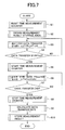
- FIG. 7 is a flow chart which shows an example of the transfer rate measurement processing by the image input and output DMAC 41 and the image transfer DMAC 44.
- FIG. 8 illustrates an example of an image for the transfer rate measurement instructions displayed on a character display unit with a touch panel provided on the operation part 6.
- the data saved in the "measurement result preservation area" in the memory is output to the memory control part 43 at a predetermined timing (the image input and output DMAC 41 regards this result as “the first transfer rate data”, and while the image transfer DMAC 44 regards this result as “second transfer rate data”, respectively).
- the transfer rate measurement processing by the image input and output DMAC 41 or the image transfer DMAC 44 described above can also be made to start automatically at a time of input of the image data from the image reading part 1 (or the Fax section 3).
- the data for transfer rate measurement set up beforehand is not used, but a part of image data input from the image reading part 1 (or the FAX section 3) is used, and “transfer rate measurement processing" can thus be performed therewith.
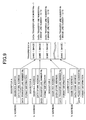
- FIG. 9 illustrates the recognition processing of the progress state of the data transfer by the image input and output DMAC 41 and the image transfer DMAC 44.
- the image input and output DMAC 41 divides the descriptor used by the image input and output DMAC 41 for a plurality of bands (in this example, 11 bands) of the transfer data to be transferred from the image reading part 1 to the image memory 42, as shown in FIG. 9, in order to recognize the progress state of data transfer, for example. Then, the number Na of data transfer lines of the descriptor A for the first band (the number of division lines) is set as "1".
- each the numbers Nb, Nc,..., Nk of data transfer lines of the descriptors B, C, ..., K is set up as follows. That is, the remaining number of data transfer lines (the number obtained through subtraction of "1" from the total number of lines for a predetermined set of image data, for example, a page of data) being then divided by ten. Furthermore, the least significant bit of the format information of the descriptor A, B, C, ..., or K for each of the first, second, third, ..., eleventh bands of transfer data is set as "0" (so that CPU interruption occurs). In addition, the above-mentioned total number of lines shall be beforehand specified by the system control part 7 here.
- the image input and output DMAC 41 can acquire the number of data lines transferred until the present time based on the number of data transfer lines of the descriptor corresponding to the band of image data each time of occurrence of CPU interruption caused by the data transfer of the relevant band of transfer data being finished. Thereby, the progress state of transfer of image data can be recognized with the number of transfer lines.
- the progress state of the data transfer to the image memory 42 from the image reading part 1 can be recognized by ten divisions.
- the progress rate of the data transfer from the image reading part 1 to the image memory 42 can be recognized more finely by increasing the number of divisions of the above-mentioned descriptor.
- the image transfer DMAC 44 can also recognize the progress state at a time of carrying out data transfer from the image memory 42 to HDD 48 through the compression/decompression unit 46, as a result of the descriptor which the image transfer DMAC44 uses is divided for 11 bands of relevant transfer data. Then, similarly, the number Na of data transfer lines of the descriptor A for the first band is set up with "1.” Furthermore, for each of the second, third, ⁇ , eleventh bands, each of the numbers Nb, Nc, ⁇ , Nk of data transfer lines of each of the descriptors B, C, ⁇ , K for the 11th band is set as the value obtained by dividing by ten the remaining number of image lines after subtraction of "1" from the total number of transfer data lines. Furthermore, similarly, the least significant bit of the format information of each descriptor A, B, C, ⁇ , or K for the respective band is set as "0" (such that CPU interruption occurs).
- FIG. 10 is a flow chart which shows an example of transfer start timing determination processing by the memory control part 43.
- FIG. 11 is a flow chart which shows an example of transfer start processing by the image input and output DMAC 41 and the image transfer DMAC44.
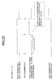
- FIG. 12 is a flow chart which shows an example of CPU interruption processing by the memory control part 43.
- FIG. 13 is a flow chart which shows another example of transfer start timing determination processing by the memory control part 43.
- the memory control part 43 can set up the data transfer start timing between the image reading part 1 and the image memory 42, and the data transfer start timing between the image memory 42 and HDD 48, independently.
- image input instructions are output to the image input and output DMAC 41, while image transfer instructions (image compression instructions) are output to the image transfer DMAC 44, respectively, and the following processing is performed.
- processing of loading each descriptor prepared for the image input and output DMAC 41 or the image transfer DMAC 44 corresponding the image data of each band of division obtained as described above to each "descriptor storing register" prepared correspondingly is performed.
- processing of resetting the number 'sum_line1' of the lines transferred (accumulated data) between the image reading part 1 and the image memory 42 into "0" is performed on the image input and output DMAC 41 (in a step S21).
- processing of resetting the number 'sum_line2' of the lines transferred (accumulated data) between the image memory 42 and HDD 48 into "0” is performed on the image transfer DMAC 44 (in a step S21).
- data transfer 1 start time a time (referred to as “data transfer 1 start time") to be inserted until the image input and output DMAC 41 starts the data transfer between the image reading part 1 and the image memory 42 (data transfer 1) is determined (in a step S22). Then, processing of setting the data transfer 1 start time onto the image input and output DMAC 41 is performed.
- a time (referred to as “data transfer 2 start time") to be inserted until the image transfer DMAC 44 starts the data transfer between the image memory 42 and HDD48 (data transfer 2) is determined (in a step S23). Then, the data transfer 2 start time is set onto the image transfer DMAC 44.
- the data transfer start timing by the image transfer DMAC 44 shall be determined such that the data transfer end time on the image input-and-output DMAC41 and the data transfer end time on the image transfer DMAC44 be coincident. Then, the corresponding data transfer 1 start time and corresponding data transfer 2 start time are set on the image input and output DMAC 41 and the image transfer DMAC44, respectively.
- the data transfer start timing by the image transfer DMAC 44 shall be determined such that the data transfer by the image transfer DMAC44 should not pass by the data transfer by the image input and output DMAC41. Then, the corresponding data transfer 1 start time and corresponding data transfer 2 start time are set on the image input and output DMAC 41 and the image transfer DMAC 44, respectively.
- the memory control part 43 sets the next data transfer 1 start time on the image input and output DMAC 41 (in the step S22), and sets the next data transfer 2 start time as the image transfer DMAC 44 (in the step S23). Then, after repeating the same processing as described above and then completing data transfer of the last band (Yes of in a step S25), processing of FIG. 10 is ended.
- step S53 data processing is performed on input image data from the image input and output DMAC 41 (in a step S53) before being written into the image memory 42 such as to achieve rotation of the relevant image
- the data transfer start timing by the image transfer DMAC 44 is determined (in a step S55) such that, after the data transfer by the image input and output DMAC41 is completed, the data transfer by the image transfer DMAC 44 is started.
- the corresponding data transfer 1 start time and corresponding data transfer 2 start time are set on the image input and output DMAC 41 and the image transfer DMAC 44, respectively (in steps S52 and S55).
- steps S51 and S52 are the same as in the steps S21 and S22 of FIG.
- steps S55 and S56 are the same as the step S23 of FIG.
- steps S54 and S57 are the same as the step S24 of FIG. 10.
- a time measurement counter A (timer) is reset (in a step S32), and the data transfer to the image memory 42 from the image reading part 1 is started (in a step S33).
- the memory control part 43 acquires the measurement time (count value) 't' from the time measurement counter A in the image input and output DMAC 41 as the data transfer time 'time 1' by the image input and output DMAC 41, as shown in FIG. 12, whenever CPU interruption occurs in the image input and output DMAC 41 (in a step S41). Then, after that, the number of data transfer lines 'line 1' of the descriptor which corresponds to the amount of data transfer performed by the image input and output DMAC 41 is acquired, and it is added to the number 'sum_line1' of accumulated number of data transfer lines by the image input and output DMAC 41 (in a step S42).
- the memory control part 43 acquires the measurement time 't' from the time measurement counter B in the image transfer DMAC 44 as the data transfer time 'time2' by the image transfer DMAC 44, as shown in FIG. 12, whenever CPU interruption occurs in the image transfer DMAC 44 (in a step S41). Then, after that, the number of data transfer lines 'line2' of the descriptor which corresponds to the amount of data transfer performed by the image transfer DMAC 44 is acquired, and it is added to the number 'sum_line2' of accumulated number of data transfer lines by the image transfer DMAC 44 (in a step S42).
- the memory control part 43 controls acquisition/release of the resource of HDD 48, and the HDD controller 47, and permits exclusive control at a time of resource acquisition only at a time of the data transfer by the image transfer DMAC 44.
- the memory control part 43 recognizes the data transfer rate between the image reading parts 1 (or the FAX section 3) and the image memory 42 by the image input and output DMAC 41, the progress state of the data transfer, the data transfer rate between the image memories 42 and HDD 48 by the image transfer DMAC 44, and the progress state of the data transfer, respectively. Then, based on those recognized results, the data transfer start timing from the image memory 42 to HDD 48 with respect to the data transfer start timing from the image reading part 1 to the image memory 42 is determined.
- the memory control part 43 controls acquisition/release of the resource of HDD 48 through the HDD controller 47, and permits exclusive control at a time of resource acquisition only at a time of the data transfer by the image transfer DMAC 44. Consequently, since it is possible to minimize the time 'for which HDD 48 is occupied, the use efficiency of HDD 48 can also be raised.
- the transfer start timing from the image memory to HDD is too early, while transferring the image data from the scanner to the image memory, a situation occurs in that no image data which should be transferred to HDD from the image memory remains in the image memory, as mentioned above.
- the data transfer (transfer to HDD from image memory) start timing by the image transfer DMAC 44 is determined namely, delayed so that the data transfer (transfer to HDD from the image memory) by the image transfer DMAC 44 do not pass by the data transfer (transfer to the image memory from a scanner) by the image input and output DMAC 41.
- the data transfer (data transfer to HDD from image memory) start timing by the image transfer DMAC 44 is determined namely, delayed so that, after writing in the image memory 42 and the data transfer (processing by which the image data is written in the image memory after the above-mentioned image rotation processing) by the image input and output DMAC 41 is completed, the data transfer by the image transfer DMAC44 be started. Consequently, complicated transfer control becomes unnecessary and a load of the CPU of the memory control part 43 can be effectively reduced.
- the image input and output DMAC 41 and the image transfer DMAC 44 may measure data transfer rates in response to instructions input from the operation part 6 corresponding to key operation on the operation part 6 by a user. Consequently, such measurement processing may be performed only at a time of replacement occasion of storage/image reading device. Therefore, it is possible to eliminate a possibility of lowering the productivity of the copier by always carrying out such measurement processing. That is, no adverse affection on the copy productivity in the digital copier occurs. Moreover, as always carrying out the measurement processing is avoided, load of the CPU of the memory control part 43 is also effectively reduced.
- to measure the data transfer rate may be performed at a time of input of image data by the image input and output DMAC 41, in each of the image input and output DMAC 41 and image transfer DMAC 44. Consequently, there is no need that a user inputs measurement instructions of data transfer rate to the image input and output DMAC41 and the image transfer DMAC 44 by key operation on the operation part 6. Therefore, load of the user may be effectively reduced.
- image data transformed may be once stored in an image memory, i.e., a semiconductor memory or the like, and, then, after that, data transfer is made from the image memory to a mass storage, i.e., HDD or the like.
- image memory i.e., a semiconductor memory or the like
- mass storage i.e., HDD or the like
- an image processing apparatus which has an image storage system including a secondary storage (mass storage device) for saving image data which has been once memorized by a primary storage (semiconductor memory), it becomes possible to efficiently store image data after undergoing image data conversion/transformation processing such as data compression into the secondary storage via the primary storage. Consequently, it becomes possible to improve, the productivity/yield of the image processing apparatus, without substantial cost rise.
- a secondary storage mass storage device
- a digital copier according to the second embodiment of the present invention has the same configuration as the digital copier according to the first embodiment described above. Therefore, duplicated description is omitted as much as possible, and a description will be made in detail especially only within portions which are different from the first embodiment.
- FIG. 14 shows a block diagram corresponding to FIG. 1 of the first embodiment.
- the image memory 42 includes semiconductor storage cells, such as DRAMs, as in the same image memory 42 as the first embodiment.
- 4 M bytes for a memory area ("ordinary image memory area" 42a) which can store binary image data for a A3 size by 400dpi as in the first embodiment usually used as a memory for image storage.
- the memory control part 43 can secure the above-mentioned conversed image memory area 42b in the image memory 42 according to instructions from the system control part 7.
- the memory control part 43 includes CPU and logic circuit, communicates with the system control part 7, receives instructions, and performs a setup of parameters, and thus performs reading-out and the writing-in of image data from/to the image memory 42 according to the instructions.
- the memory control part 43 in the second embodiment can also perform the following processing.
- first transfer rate data is received from the image input and output DMAC 41
- the first transfer rate is recognized by analyzing the data by the memory control part.
- second transfer rate data is received from the HDD controller 47
- the second transfer rate is recognized by analyzing the data thereby.
- compression processing rate data is received from the compression/decompression unit 46
- the compression processing rate of the compression/decompression unit 46 is recognized by analyzing the data thereby.
- first progress state data is received from the image input and output DMAC 41
- the memory control part 43 recognizes a first progress state (progress state of the data transfer to the ordinary image memory area 42a in the image memory 42 from the image reading part 1 or from the FAX section 3) by analyzing the data.
- conversion memory progress state data is received from the code transfer DMAC 45
- conversion, memory progress state (progress state of data transfer to the "converted image memory area" 42b in the image memory 42 from the compression/decompression unit 46) is recognized by analyzing the data thereby.
- a second progress state (progress state of data transfer to HDD48 from the "converted image memory area" 42b in the image memory 42) is recognized by analyzing the data thereby.
- a progress state (referred to as a "conversion memory progress state") of data transfer to the "converted image memory area" 42b in the image memory 42 from the compression/decompression unit 46 is recognized, and it is output to the memory control part 43 by using the recognition result as the conversion memory transfer progress state data.
- a data transfer rate (referred to as a "second transfer rate") from the "converted image memory area” 42b in the image memory 42 to HDD 48 is measured. The measurement result is then output to the memory control part 43 as the second transfer rate data.
- a progress state (refereed to as a "second progress state") of data transfer to HDD 48 from the converted image memory area 42b in the image memory 42 is recognized, and the recognition result is output to the memory control part 43 as the second progress state data.
- the difference calculation part 54 subtracts the number of input-and-output processing lines output from the image input and output DMAC41 from the number of transfer processing lines output from the image transfer DMAC 44, and outputs the subtraction result as the line number difference to the difference comparison part 55.
- the difference comparison part 55 when the line number difference is "0", masks a transfer memory access request signal from the image transfer DMAC 44, and thereby, data transfer processing to the image transfer DMAC 44 from the image memory 42 is stopped. Consequently, passing by of the memory address is prevented beforehand. That is, the memory address output from the transfer image address counter part 52 is prevented from becoming larger than the memory address output from the input-and-output image address counter part 51. That is, data transfer to the compression/decompression unit 46 from the image memory 42 is prevented from passing by data transfer to the image memory 42 from the image reading part 1.
- the first transfer rate in the first embodiment indicates data transfer rate from the image reading part 1 to "the ordinary image memory area" 42a in the image memory 42, in the transfer rate recognition processing by the memory control part 43.
- the device name, the version, and compression processing rate of each type of compression/decompression device which can be used by this system is stored in an internal memory of the system control part 7 by using as a data table, by an operation signal beforehand input by key operation on the operation part 6.
- the system control part 7 reads the device name and version on the compression/decompression unit 46 actually mounted in the system, and the compression processing rate of the compression/decompression unit 46 is acquired by referring to the data table at a time of initial setup of the system, and information indicating the compression processing rate is added to the process execution instructions to be transmitted to the memory control part 43.
- the memory control part 43 can recognize the compression processing rate of the compression/decompression unit 46 by analyzing the data added to the instructions, when the process execution instructions are received from the system control part 7.
- the second transfer rate (data transfer rate from the converted image memory area 42b in the image memory 42 to HDD 48) which is the data transfer rate by the HDD controller 47 depends on the writing rate of HDD 48.
- FIG. 7 is a flow chart which shows an example of the compression processing rate measurement processing by the compression/decompression unit 46 and the transfer rate measurement processing by the image input and output DMAC41 and the HDD controller 47.
- FIG. 8 shows an example of a transfer rate measurement instruction image displayed on a character display device with a touch panel on the operation part 6 (exterior) not shown.
- Each of the compression/decompression unit 46, the image input and output DMAC 41, and the HDD controller 47 starts processing of FIG. 7, in response to instructions for measurement of data transfer rate (key of "Yes” on “memory data transfer rate measurement” of FIG. 8 being pressed), by which measurement of data transfer rate is directed via the memory control part 43 by the system control part 7, by key operation on the operation part 6.
- a time measurement counter is reset (in a step S1), and a "measurement result preservation area" is secured to the memory (in a step S2), and a notice of a data transfer start from the memory control part 43 is waited for (in a step S3).
- the least significant bit of the format information on the corresponding descriptor memorized by the internal memory is set as "0" so that CPU interruption occurs at a time data transfer (for example, 1 byte of data transfer) ends.
- the data saved in the "measurement result preservation area" in the memory is output to the memory control part 43 at a predetermined timing. That is, the image input and output DMAC 41 outputs this data as the first transfer rate data; the HDD controller 47 outputs it as the second transfer rate data; and the compression/decompression unit 46 output it as the compression processing rate data, respectively.
- the memory control part 43 can recognize the first transfer rate by analyzing the data, when the first transfer rate data is received from the image input and output DMAC41.
- the second transfer rate data is received from the HDD controller 47, the second transfer rate can be recognized by analyzing the data thereby.
- the compression processing rate data is similarly received from the compression/decompression unit 46, the compression processing rate can be recognized by analyzing the data thereby.
- the compression processing rate (speed) measurement processing and transfer rate measurement processing by the compression/decompression unit 46, the image input and output DMAC41, and the HDD controller 47 described above can also be automatically started at a time of the input of the image data from the image reading part 1 (or the FAX section 3).
- the data prepared for transfer rate measurement set up beforehand is not needed, but a part of image data actually input from the image reading part 1 (or the FAX section 3) is used, and transfer rate measurement processing or compression speed measurement processing can be performed therewith.
- the compression/decompression unit 46 measures the compression processing rate by the same processing as in the image input and output DMAC 41 and the HDD controller 47 at the same timing, and after saving the data indicating the measurement result into the measurement result preservation area in the memory, it is output to the memory control part 43 at predetermined timing as the compression processing rate data. Therefore, when the memory control part 43 receives the compression processing rate data from the compression/decompression unit 46 as mentioned above, the compression processing rate on the compression/decompression unit 46 can be recognized by analyzing the data, thereby.
- the image input and output DMAC 41 may recognize the progress state of the data transfer to the ordinary image memory area 42a in the image memory 42 from the image reading part 1, for example, as shown in FIG. 9, the descriptor which the image input and output DMAC 41 uses is divided for a plurality of bands (in this example, 11 bands) of the relevant transfer data, and the number (divided line number) Na of data transfer lines on the descriptor A for the first band is set as "1.” Furthermore, for each of the second, third, ⁇ , and eleventh bands, each of the numbers Nb, Nc, ..., Nk of data transfer lines on the respective descriptor B, C, ⁇ , K is set as the value obtained by division with ten the remaining number after subtraction of "1" from the total number of lines of a predetermined set of image data, for example, a page of image data).
- the least significant bit of the format information on each of the descriptor A, B, C, ⁇ , K for the first, second, third, ⁇ , eleventh bands is set as "0" (so that CPU interruption may occur).
- the total number of lines shall be beforehand specified by the system control part 7.
- the image input and output DMAC 41 can acquire the number of data transfer lines at the present time based on the number of data transfer lines of the descriptor corresponding to the image data at the time of CPU interruption. Thereby, the progress state of transfer of image data can be recognized by the number of transfer lines.
- the progress state of the data transfer to the ordinary image memory area in the image memory 42 from the image reading part 1 can be recognized by ten divisions. It becomes possible by increasing the number of divisions of the descriptor to raise the recognition accuracy of the progress state of the data transfer to the ordinary image memory area 42a in the image memory 42 from the image reading part 1.
- the code transfer DMAC 45 may recognize the progress state of the data transfer to the converted image memory area 42b in the image memory 42 from the compression/decompression unit 46.
- the descriptor which the code transfer DMAC45 uses is divided for 11 bands of transfer data. Then, the number Na of data transfer lines of the descriptor A for the first band is set up with "1", and for the second, third, ⁇ , eleventh bands, each of the numbers Nb, Nc, ⁇ , Nk of data transfer lines on each descriptor B, C, ⁇ , K is set as the value obtained by dividing the remaining number.
- the code transfer DMAC 45 can recognize the progress state of the data transfer to the converted image memory area 42b in the image memory 42 from the compression/decompression unit 46 by ten divisions. It becomes possible by increasing the number of divisions of the descriptor to raise the recognition accuracy of the progress state of the data transfer to the converted image memory area 42b in the image memory 42 from the compression/decompression unit 46.
- the HDD controller 47 divides into 11 bands of transfer data the descriptor which the HDD controller 47 uses, in order to recognize the progress state of data transfer from the converted image memory area 42b to HDD 48 in the image memory 42. Then, the number Na of data transfer lines of the descriptor A for the first band is set up with "1.” Then, for the second, third, ⁇ , eleventh bands of transfer data, each of the numbers Nb, Nc, ⁇ , Nk of data transfer lines on each descriptor B, C, ⁇ , K is set as the value obtained by division with ten the remaining numbers of image lines.
- the HDD controller 47 can recognize the progress state of the data transfer to HDD 48 from the converted image memory area 42b in the image memory 42 by ten divisions.
- the recognition accuracy of the progress state of data transfer from the converted image memory area in the image memory 42 to HDD 48 can be raised by increasing the number of divisions of the descriptor.
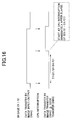
- FIG. 15 is a flow chart which shows an example of data transfer processing by the memory control part 43 in the second embodiment.
- the amount (the number of data transfer lines per one descriptor by the image input and output DMAC 41) of the image data written in the ordinary image memory area 42a in the image memory 42 by the image input and output DMAC 41 is referred to as D1 (bytes) ; the amount (the number of data transfer lines per one descriptor by the code transfer DMAC 45) of the code data written in the converted image memory area 42b in the image memory 42 by the code transfer DMAC 45 is referred to as D2 (bytes);
- the data transfer rate (first transfer rate) by the image input and output DMAC 41 is referred to as S1 (bytes/second);
- the compression processing rate (data transfer rate from the compression/decompression unit 46 to the converted image memory area 42b in the image memory 42) with the compression/decompression unit 46 referred to as C1 (bytes/second); and the data transfer rate (second transfer rate) by to the HDD controller 47 is set to S2 (bytes/second).
- FIG. 17 is a timing chart for illustrating the data transfer start timings by the image transfer DMAC 44 and the code transfer DMAC 45 when the compression processing rate C1 with the compression/decompression unit 46 is slower than the data transfer rate S1 by the image input and output DMAC 41 (No of in a step S61).
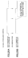
- FIG. 18 is a timing chart for illustrating the data transfer start timing (data transfer start timing from the converted image memory area 42b in the image memory 42 to HDD 48) by the HDD controller 47 when the compression processing rate C1 with the compression/decompression unit 46 is slower than the data transfer rate (second transfer rate) S2 by the HDD controller 47 (Yes of in a step S64).
- FIG. 19 is a timing chart for illustrating the data transfer start timing by the HDD controller 47 when the data transfer rate S2 by the HDD controller 47 is slower than the compression processing rate C1 with the compression/decompression unit 46 (No of in a step S64).
- the memory control part 43 secures the converted image memory area 42b beforehand in the image memory 42.
- image data transferred to the ordinary image memory area 42a in the image memory 42 from the image reading part 1 or the FAX section 3 when CPU interruption occurs in the image input and output DMAC 41 when transfer of the image data of the number of data transfer lines on one descriptor is completed, this fact is recognized with the first progress state data from the image input and output DMAC 41, and processing of FIG. 15 is started.
- S1 which is the first transfer rate to memory area 42a of the image memory 42 and the compression processing rate C1 are measured first (in a step S61).
- the first transfer rate S1 can be measured from the actual data transfer result of the number of data transfer lines on one descriptor, while the compression processing rate C1 can be acquired from the data setup beforehand.
- the data transfer start timing is determined such that data transfer by the image transfer DMAC 44 and the code transfer DMAC 45 is started immediately (at the time of the first CPU interruption occurrence in the image input and output DMAC 41 immediately after starting of the data transfer by the image input and output DMAC 41). Then, the image transfer DMAC44 and the code transfer DMAC45 are started according to this timing (in a step S63).
- the image data written in the ordinary image memory area 42a in the image memory 42 by the image input and output DMAC41 is transferred to the compression/decompression unit 46 by the image transfer DMAC44.
- the code data which is image data after the compression processing with the compression/decompression unit 46 is transferred and written in the converted image memory area 42b secured in the image memory 42 by the code transfer DMAC 45.
- the data transfer start timing is determined by processing a step S66 so that, at the time of the first CPU interruption occurrence in the code transfer DMAC 45 immediately after starting of the data transfer by the image transfer DMAC 44 and the code transfer DMAC 45, the data transfer by the HDD controller 47 is started. Then, the HDD controller 47 is started according to the timing.
- the code data written in the converted image memory area 42b in the image memory 42 by the code transfer DMAC45 is transferred to HDD 48, and is written in on the HD, by the starting (in a step S65 or S66) of this HDD controller 47.
- acquisition/release of the resource of HDD 48 is also controllable through the HDD controller 47.
- exclusive control at the time of resource acquisition of HDD 48 can be permitted only at the time of the data transfer by the HDD controller 47, and the exclusive control at the time of resource acquisition of HDD 48 can be performed at the time of the data transfer.
- CPU interruption processing for recognizing the progress state of processing, i.e., the data transfer by the code transfer DMAC 45, by CPU interruption-generated by the code transfer DMAC 45 is not performed. Thereby, the processing at the time of the data transfer by the HDD controller 47 is independently controllable.
- FIGS. 20A and 20B show a timing chart for illustrating processing in case the memory control part 43 performs the exclusive control at the time of resource acquisition of HDD 48.
- FIGS. 21A and 21B show a timing chart for illustrating processing in case the memory control part 43 does not perform the exclusive control even at the time of resource acquisition of HDD 48.
- FIG. 20A and FIG. 21A show the minimum time required for the data transfer by the HDD controller 47.
- processing by CPU interruption generated by the code transfer DMAC 45 is not performed when the memory control part 43 performs the exclusive control at the time of resource acquisition of HDD 48, as shown in FIG. 20B, the time required for the data transfer by the HDD controller 47 does not increase, and, thus, the time is always the minimum time.
- the memory control part 43 it is preferable to determine the data transfer start timing by the image transfer DMAC 44 and the code transfer DMAC 45 such that the end time of the data transfer by the image input and output DMAC 41 be coincident with the end time of the data transfer by the image transfer DMAC 44 and the code transfer DMAC45.
- FIG. 22 is a timing chart in another example of illustrating data transfer start timing by the image transfer DMAC 44 and the code transfer DMAC 45 when the data transfer rate S1 by the image input and output DMAC 41 is slower than the compression processing rate C1 with the compression/decompression unit 46.
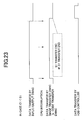
- FIG. 23 is a timing chart in another example of illustrating data transfer start timing by the image transfer DMAC 44 and the code transfer DMAC 45 when the compression processing rate C1 with the compression/decompression unit 46 is slower than the data transfer rate S1 by the image input and output DMAC 41.
- the data transfer start timing is determined so that, after the data transfer by the image input and output DMAC 41 is started, T1 (D1/S1 - D1/C1) elapses, and, then, the data transfer by the image transfer DMAC 44 and the code transfer DMAC45 be started at the time of CPU interruption generated subsequently by the image input and output DMAC 41.
- the image transfer DMAC 44 and the code transfer DMAC45 are started according to the timing.
- the data transfer start timing is determined such that the data transfer by the image transfer DMAC 44 and the code transfer DMAC 45 be started at the time of the first CPU interruption generated by the image input and output DMAC41 immediately after starting of the data transfer by the image input and output DMAC41, as shown in FIG. 23. Then, according to the timing, the image transfer DMAC 44 and the code transfer DMAC 45 are started.
- the memory control part 43 rotates image data input from the image input and output DMAC 41 and writes the result into the ordinary image memory area in the image memory 42, it is preferable'that, after the data transfer (writing into the ordinary image data area of the image memory after the image rotation) by the image input and output DMAC 41 is completed, the data transfer by the image transfer DMAC 44 and the code transfer DMAC 45 be started.
- the memory control part 43 may be made to perform the following control operation, when the amount (for example, the number of data transfer lines on one descriptor by the image input and output DMAC 41) of image data written in the ordinary image memory area in the image memory 42 by the image input and output DMAC41 exceeds a predetermined amount (capacity of the ordinary image memory area of the image memory 42) set up beforehand. That is, the above-mentioned series of data transfer operation performed by the image transfer DMAC 44, the code transfer DMAC 45, and the HDD controller 47 are not performed, but, instead, a series of image transfer operations performed by the image transfer DMAC44 and the HDD controller 47 are performed.
- the image data written in the ordinary image memory area 42a in the image memory 42 by the image input and output DMAC41 is transferred to the compression/decompression unit 46 by the image transfer DMAC 44, and by the HDD controller 47, the code data which is image data after the compression processing with the compression/decompression unit 46 is transferred directly to HDD 48, and then, is written into the HD.
- the compression processing rate with the compression/decompression unit 46, the data transfer rate (data transfer rate from the converted image memory area 42b in the image memory 42 to HDD 48) by the HDD controller 47, and the progress state of the data transfer by the code transfer DMAC 45 are recognized, respectively. Then, based on the recognition results, the data transfer start timing by the HDD controller 47 is determined.
- the image data input from the image reading part 1 or the FAX section 3 can be efficiently transferred to HDD 48 with high accuracy via the image memory 42 and compression/decompression unit 46, without substantially modifying/altering software, even when data transfer rate changes according to replacement of the various sets of hardware containing the image reading part 1, the FAX section 3, HDD 48, and the compression/decompression unit 46.
- the memory control part 43 it is preferable to control acquisition/release of the resource of HDD 48 through the HDD controller 47, and to permit the exclusive control at the time of resource acquisition only at the time of the data transfer by the HDD controller 47. Consequently, since occupying HDD 48 uselessly is avoided, the use efficiency of HDD 48 can also be raised.
- the memory control part 43 to performs a control such that, in case the data transfer rate by the image input and output DMAC 41 is slower than the compression processing rate with the compression/decompression unit 46, the data transfer start timing by the image transfer DMAC 44 and the code transfer DMAC 45 is determined such that the end time of the data transfer by the image input and output DMAC41 coincides with the end time of data transfer by the image transfer DMAC 44 and the code transfer DMAC 45.
- the memory control part 43 rotates the image data input from the image input and output DMAC 41, and then writes the result in the ordinary image memory area in the image memory 42, it is preferable that, after the data transfer by the image input and output DMAC41 is completed including image rotation processing, the data transfer by the image transfer DMAC 44 and the code transfer DMAC 45 is started. Consequently, the load of CPU in the memory control part 43 can be effectively reduced.
- the memory control part 43 reads an image of a long dimension by the image reading part 1, when a predetermined amount (capacity of the ordinary image memory area of the image memory 42) transferred by the image input and output DMAC 41 set beforehand is exceeded, it is preferable not to perform the series of data transfer operations by the image transfer DMAC 44, the code transfer DMAC 45, and the HDD controller 47, but, instead, to perform a series of data transfer operations by the image transfer DMAC 44 and the HDD controller 47. Consequently, the image data input from the image reading part 1 can be certainly transferred to HDD 48 via the image memory 42, without providing special measures.
- the function in the compression/decompression unit 46 to measure the compression processing rate; in the image input and output DMAC 41 and the HDD controller 47 each to measure the data transfer rate, respectively.
- the memory control part 43 can recognize those data transfer rate and compression processing rate by acquiring the measurement result from the compression/decompression unit 46 for the compression processing rate and the measurement result of data transfer rate from the image input and output DMAC 41 and the HDD controller 47, respectively.
- the optimal timing suitable for the characteristic of the storage after replacement can be determined as each data transfer start timing mentioned above. Therefore, it becomes possible to transfer efficiently the image data input from the image reading part 1 to HDD 48 with high accuracy via the image memory 42.
- the image input and output DMAC 41 and the HDD controller 47, and the compression/decompression unit 46 measure the data transfer rates and compression processing rate, respectively, according to the instructions from the operation part 6 corresponding to key operation on the operation part 6 by a user. Consequently, adverse affection onto the copy productivity/yield in the digital copier can be avoided. Moreover, the load of CPU of the memory control part 43 can also be reduced.
- the data transfer rate may be measured at the time of image data input by the image input and output DMAC 41 by the image input and output DMAC 41 and by the HDD controller 47, and also the compression/decompression unit 46 may measure the compression processing rate at the time of the input of the image data by the image input and output DMAC 41.
- the memory control part 43 secures the converted image memory area 42b beforehand to the image memory 42 in the second embodiment, it is also possible to perform the same operation when starting processing of FIG. 15.
- the present invention can be applied not only to this but to other image processing apparatus, such as facsimile apparatus and a printer.
- present invention is also applicable to image input/output apparatuses, such as a scanner and a network file server, also to a digital composite machine which has a plurality of functions of those image input/output apparatus and image processing apparatus.
- the present invention it is possible to make the end time of data transfer and writing into a first storage coincide with the end time of data transfer and writing from the first storage to a second storage for the same data. As a result, it is possible to avoid a situation from occurring in which no data remains in the first storage to be sent to the second storage before predetermined data transfer into the first storage is finished. Accordingly, it is possible to avoid a situation from occurring in which data transfer from the first storage to the second storage should be interrupted before the data transfer to the first storage is completed.
- each storage it is possible to achieve efficient use of each storage.
- a secondary storage such as HDD. That is, if a situation occurred in which, as the data transfer were started too early from the first storage to the second storage, the data transfer thus started should be interrupted before the completion of data transfer into the first storage, the second storage should be occupied for a uselessly long time. If so, the efficient use of the second storage would be obstructed.
Applications Claiming Priority (6)
| Application Number | Priority Date | Filing Date | Title |
|---|---|---|---|
| JP2001199435 | 2001-06-29 | ||
| JP2001199435 | 2001-06-29 | ||
| JP2001216429 | 2001-07-17 | ||
| JP2001216429 | 2001-07-17 | ||
| JP2002188183 | 2002-06-27 | ||
| JP2002188183A JP2003101741A (ja) | 2001-06-29 | 2002-06-27 | 画像処理装置、及びその制御方法、並びに制御装置 |
Publications (2)
| Publication Number | Publication Date |
|---|---|
| EP1271918A1 true EP1271918A1 (de) | 2003-01-02 |
| EP1271918B1 EP1271918B1 (de) | 2006-03-22 |
Family
ID=27347059
Family Applications (1)
| Application Number | Title | Priority Date | Filing Date |
|---|---|---|---|
| EP02014046A Expired - Fee Related EP1271918B1 (de) | 2001-06-29 | 2002-06-28 | Bildverarbeitungsvorrichtung und Steuerverfahren und -gerät dafür |
Country Status (4)
| Country | Link |
|---|---|
| US (1) | US7259876B2 (de) |
| EP (1) | EP1271918B1 (de) |
| JP (1) | JP2003101741A (de) |
| DE (1) | DE60209966T2 (de) |
Families Citing this family (26)
| Publication number | Priority date | Publication date | Assignee | Title |
|---|---|---|---|---|
| WO2002032083A1 (fr) * | 2000-10-13 | 2002-04-18 | Sony Corporation | Systeme de controle de la qualite de la communication de donnees, systeme emetteur et recepteur |
| US20040049608A1 (en) * | 2002-09-05 | 2004-03-11 | Toshiba Tec Kabushiki Kaisha | Apparatus and method for forming image |
| JP2005065043A (ja) * | 2003-08-18 | 2005-03-10 | Minolta Co Ltd | データ処理装置 |
| EP1511004A3 (de) * | 2003-08-19 | 2010-01-27 | Sony Corporation | Speichersteuerung, Speichersteuerungsverfahren, Frequenzumwandlungsvorrichtung, Frequenzumwandlunsverfahren, Bildsignalverarbeitungsvorrichtung, Bildsignalverarbeitungsverfahren und Programm zur Ausführung dieser Verfahren |
| JP3755882B2 (ja) * | 2003-11-28 | 2006-03-15 | Tdk株式会社 | 永久磁石用合金粉末の製造装置及び製造方法 |
| JP2005354605A (ja) * | 2004-06-14 | 2005-12-22 | Ricoh Co Ltd | 画像入出力装置、画像入出力方法、コンピュータプログラム及び記録媒体 |
| JP2006080876A (ja) * | 2004-09-09 | 2006-03-23 | Ricoh Co Ltd | 画像入出力装置、画像入出力方法、コンピュータプログラム及び記録媒体 |
| JP4405350B2 (ja) * | 2004-09-16 | 2010-01-27 | 株式会社リコー | 画像形成装置およびデータ漏洩防止プログラム |
| JP2008073921A (ja) * | 2006-09-20 | 2008-04-03 | Canon Inc | 印刷装置およびその制御方法 |
| JP4855917B2 (ja) * | 2006-12-07 | 2012-01-18 | 株式会社リコー | 画像形成装置、画像形成方法および画像形成プログラム |
| JP4861255B2 (ja) * | 2007-06-14 | 2012-01-25 | 株式会社リコー | 画像形成装置、画像形成方法およびプログラム |
| JP4903092B2 (ja) * | 2007-07-05 | 2012-03-21 | 株式会社リコー | 画像処理装置、画像処理制御方法、及び画像処理制御プログラム |
| JP4445532B2 (ja) * | 2007-08-24 | 2010-04-07 | 株式会社沖データ | 複合システム及び複合装置 |
| KR101615472B1 (ko) * | 2007-09-24 | 2016-04-25 | 애플 인크. | 전자 장치 내의 내장형 인증 시스템들 |
| JP2009259197A (ja) * | 2008-03-18 | 2009-11-05 | Ricoh Co Ltd | 情報処理装置およびその起動方法 |
| JP5313565B2 (ja) * | 2008-07-02 | 2013-10-09 | キヤノン電子株式会社 | 画像読取装置、画像読取方法、画像読取システム及びプログラム |
| JP5181911B2 (ja) * | 2008-08-05 | 2013-04-10 | 株式会社リコー | 画像形成装置、メモリ管理方法、及びメモリ管理プログラム |
| JP5106432B2 (ja) * | 2009-01-23 | 2012-12-26 | 株式会社東芝 | 画像処理装置、方法、及びプログラム |
| JP5444960B2 (ja) * | 2009-09-01 | 2014-03-19 | 株式会社リコー | 情報処理装置、データ移行方法及び記録媒体 |
| JP5741023B2 (ja) * | 2011-02-02 | 2015-07-01 | 株式会社リコー | 画像形成装置および画像形成方法 |
| US9697628B2 (en) * | 2011-03-18 | 2017-07-04 | Paypal, Inc. | On-demand image spriting |
| JP5899652B2 (ja) | 2011-05-09 | 2016-04-06 | 株式会社リコー | 画像形成装置、及び画像形成プログラム |
| JP2015179949A (ja) * | 2014-03-19 | 2015-10-08 | コニカミノルタ株式会社 | 画像形成装置、制御方法、および制御プログラム |
| WO2016060268A1 (ja) | 2014-10-17 | 2016-04-21 | 株式会社リコー | 車両用画像表示システム |
| US11036833B2 (en) | 2016-07-11 | 2021-06-15 | Ricoh Company, Ltd. | Image processing system, information processing method, and non-transitory computer-readable medium |
| JP7159765B2 (ja) | 2017-10-06 | 2022-10-25 | 株式会社リコー | 文書状態管理システム、文書状態管理方法、プログラム |
Citations (6)
| Publication number | Priority date | Publication date | Assignee | Title |
|---|---|---|---|---|
| EP0465093A2 (de) * | 1990-06-25 | 1992-01-08 | Xerox Corporation | Verfahren und Gerät zum Laufdrucken in einem elektronischen reprographischen Gerät |
| US5124798A (en) * | 1990-12-10 | 1992-06-23 | Fuji Xerox Co., Ltd. | Method of outputting images in a digital copying machine upon the occurrence of an input error |
| EP0705021A1 (de) * | 1994-09-28 | 1996-04-03 | Fuji Xerox Co., Ltd. | Kopiergerät |
| US6043897A (en) * | 1996-12-04 | 2000-03-28 | Minolta Co., Ltd. | Image forming apparatus |
| US6184999B1 (en) * | 1996-02-05 | 2001-02-06 | Minolta Company, Ltd. | Image processing apparatus |
| US6222636B1 (en) * | 1998-08-13 | 2001-04-24 | Nek Press Solutions Llc | Disk-based image storage system invention disclosure |
Family Cites Families (12)
| Publication number | Priority date | Publication date | Assignee | Title |
|---|---|---|---|---|
| US5294944A (en) | 1991-03-06 | 1994-03-15 | Ricoh Company, Ltd. | Color image forming apparatus having means for properly superimposing image colors on each other |
| JP2908657B2 (ja) | 1992-05-18 | 1999-06-21 | 株式会社リコー | 半導体レーザアレイ記録装置 |
| JP3315474B2 (ja) | 1993-05-13 | 2002-08-19 | 株式会社リコー | 画像形成装置 |
| JP3532048B2 (ja) | 1996-03-27 | 2004-05-31 | 株式会社リコー | デジタル複写機 |
| JPH104467A (ja) | 1996-04-18 | 1998-01-06 | Ricoh Co Ltd | 画像形成装置 |
| JPH10143660A (ja) * | 1996-11-11 | 1998-05-29 | Hitachi Ltd | 欠陥判定処理方法およびその装置 |
| US5995648A (en) * | 1997-03-18 | 1999-11-30 | Cognex Corporation | Image processing system and method using subsampling with constraints such as time and uncertainty constraints |
| US5944802A (en) * | 1997-08-28 | 1999-08-31 | International Business Machines Corporation | Dynamic speed matching of host channel and device data transfers |
| JPH11234490A (ja) | 1998-02-10 | 1999-08-27 | Ricoh Co Ltd | 画像形成装置 |
| US6891632B2 (en) * | 1998-07-17 | 2005-05-10 | Peerless Systems, Inc. | Method and apparatus for selecting print strategy for optimal performance |
| US6621940B2 (en) * | 1999-06-10 | 2003-09-16 | Xerox Corporation | Image rotation in opponent color space |
| US6894802B1 (en) * | 2000-02-25 | 2005-05-17 | Xerox Corporation | Multi-job image buffering system and method |
-
2002
- 2002-06-27 JP JP2002188183A patent/JP2003101741A/ja active Pending
- 2002-06-28 DE DE60209966T patent/DE60209966T2/de not_active Expired - Lifetime
- 2002-06-28 EP EP02014046A patent/EP1271918B1/de not_active Expired - Fee Related
- 2002-06-28 US US10/183,499 patent/US7259876B2/en not_active Expired - Fee Related
Patent Citations (6)
| Publication number | Priority date | Publication date | Assignee | Title |
|---|---|---|---|---|
| EP0465093A2 (de) * | 1990-06-25 | 1992-01-08 | Xerox Corporation | Verfahren und Gerät zum Laufdrucken in einem elektronischen reprographischen Gerät |
| US5124798A (en) * | 1990-12-10 | 1992-06-23 | Fuji Xerox Co., Ltd. | Method of outputting images in a digital copying machine upon the occurrence of an input error |
| EP0705021A1 (de) * | 1994-09-28 | 1996-04-03 | Fuji Xerox Co., Ltd. | Kopiergerät |
| US6184999B1 (en) * | 1996-02-05 | 2001-02-06 | Minolta Company, Ltd. | Image processing apparatus |
| US6043897A (en) * | 1996-12-04 | 2000-03-28 | Minolta Co., Ltd. | Image forming apparatus |
| US6222636B1 (en) * | 1998-08-13 | 2001-04-24 | Nek Press Solutions Llc | Disk-based image storage system invention disclosure |
Also Published As
| Publication number | Publication date |
|---|---|
| DE60209966T2 (de) | 2006-10-19 |
| US7259876B2 (en) | 2007-08-21 |
| US20030011821A1 (en) | 2003-01-16 |
| DE60209966D1 (de) | 2006-05-11 |
| JP2003101741A (ja) | 2003-04-04 |
| EP1271918B1 (de) | 2006-03-22 |
Similar Documents
| Publication | Publication Date | Title |
|---|---|---|
| US7259876B2 (en) | Image processing apparatus, and, control method and control device therefor | |
| US6708234B2 (en) | Data processing apparatus and DMA data transfer method | |
| US7218412B2 (en) | Apparatus, method and computer readable recording medium for processing image information | |
| EP0751675B1 (de) | Bilderzeugungsgerät | |
| JPH03217976A (ja) | 画像処理システム | |
| US7301653B2 (en) | Image processing apparatus, image processing method, and storage medium | |
| JP2002140286A (ja) | 情報処理装置及びdma転送方法 | |
| JP3967074B2 (ja) | 画像処理装置および画像形成装置 | |
| JP4253138B2 (ja) | 画像形成装置 | |
| JP4212200B2 (ja) | 画像処理システム | |
| JP2000069257A (ja) | 画像処理装置 | |
| JP2005079646A (ja) | 画像形成装置 | |
| JP3932275B2 (ja) | 画像入出力装置 | |
| JP4076224B2 (ja) | 画像形成装置 | |
| JP2002244994A (ja) | 画像形成装置 | |
| JP5001223B2 (ja) | 画像読取装置 | |
| JP2005260846A (ja) | 画像情報装置および画像データ転送方法 | |
| JP2005072987A (ja) | 画像形成装置 | |
| JP2002135544A (ja) | 画像処理装置 | |
| JP2005236578A (ja) | 画像形成装置および画像読み取り方法 | |
| JP2003298820A (ja) | 画像形成装置 | |
| JP2004080135A (ja) | 画像処理装置 | |
| JP2005079653A (ja) | 画像形成装置 | |
| JP2006001195A (ja) | 画像形成装置 | |
| JP2004289229A (ja) | 画像形成装置 |
Legal Events
| Date | Code | Title | Description |
|---|---|---|---|
| PUAI | Public reference made under article 153(3) epc to a published international application that has entered the european phase |
Free format text: ORIGINAL CODE: 0009012 |
|
| 17P | Request for examination filed |
Effective date: 20020628 |
|
| AK | Designated contracting states |
Kind code of ref document: A1 Designated state(s): AT BE CH CY DE DK ES FI FR GB GR IE IT LI LU MC NL PT SE TR |
|
| AX | Request for extension of the european patent |
Free format text: AL;LT;LV;MK;RO;SI |
|
| 17Q | First examination report despatched |
Effective date: 20030423 |
|
| AKX | Designation fees paid |
Designated state(s): DE FR GB |
|
| GRAP | Despatch of communication of intention to grant a patent |
Free format text: ORIGINAL CODE: EPIDOSNIGR1 |
|
| GRAC | Information related to communication of intention to grant a patent modified |
Free format text: ORIGINAL CODE: EPIDOSCIGR1 |
|
| GRAS | Grant fee paid |
Free format text: ORIGINAL CODE: EPIDOSNIGR3 |
|
| GRAA | (expected) grant |
Free format text: ORIGINAL CODE: 0009210 |
|
| AK | Designated contracting states |
Kind code of ref document: B1 Designated state(s): DE FR GB |
|
| REG | Reference to a national code |
Ref country code: GB Ref legal event code: FG4D |
|
| REF | Corresponds to: |
Ref document number: 60209966 Country of ref document: DE Date of ref document: 20060511 Kind code of ref document: P |
|
| ET | Fr: translation filed | ||
| PLBE | No opposition filed within time limit |
Free format text: ORIGINAL CODE: 0009261 |
|
| STAA | Information on the status of an ep patent application or granted ep patent |
Free format text: STATUS: NO OPPOSITION FILED WITHIN TIME LIMIT |
|
| 26N | No opposition filed |
Effective date: 20061227 |
|
| PGFP | Annual fee paid to national office [announced via postgrant information from national office to epo] |
Ref country code: FR Payment date: 20110630 Year of fee payment: 10 |
|
| PGFP | Annual fee paid to national office [announced via postgrant information from national office to epo] |
Ref country code: GB Payment date: 20110620 Year of fee payment: 10 |
|
| PGFP | Annual fee paid to national office [announced via postgrant information from national office to epo] |
Ref country code: DE Payment date: 20110622 Year of fee payment: 10 |
|
| GBPC | Gb: european patent ceased through non-payment of renewal fee |
Effective date: 20120628 |
|
| REG | Reference to a national code |
Ref country code: FR Ref legal event code: ST Effective date: 20130228 |
|
| REG | Reference to a national code |
Ref country code: DE Ref legal event code: R119 Ref document number: 60209966 Country of ref document: DE Effective date: 20130101 |
|
| PG25 | Lapsed in a contracting state [announced via postgrant information from national office to epo] |
Ref country code: GB Free format text: LAPSE BECAUSE OF NON-PAYMENT OF DUE FEES Effective date: 20120628 Ref country code: FR Free format text: LAPSE BECAUSE OF NON-PAYMENT OF DUE FEES Effective date: 20120702 Ref country code: DE Free format text: LAPSE BECAUSE OF NON-PAYMENT OF DUE FEES Effective date: 20130101 |